JP6349511B2 - Bullet ball machine - Google Patents
Bullet ball machine Download PDFInfo
- Publication number
- JP6349511B2 JP6349511B2 JP2014019293A JP2014019293A JP6349511B2 JP 6349511 B2 JP6349511 B2 JP 6349511B2 JP 2014019293 A JP2014019293 A JP 2014019293A JP 2014019293 A JP2014019293 A JP 2014019293A JP 6349511 B2 JP6349511 B2 JP 6349511B2
- Authority
- JP
- Japan
- Prior art keywords
- effective period
- determination
- effect
- period
- control device
- Prior art date
- Legal status (The legal status is an assumption and is not a legal conclusion. Google has not performed a legal analysis and makes no representation as to the accuracy of the status listed.)
- Active
Links
Images


Description
本発明は、遊技者によって操作可能な操作手段を備えた遊技機に関するものである。 The present invention relates to a gaming machine provided with operating means that can be operated by a player.
従来のパチンコ機では、遊技者が発射ハンドルを操作することで遊技球が発射され、発射ハンドルの回動量を変化させることにより発射威力を変更させ、遊技領域に設けられた入賞口を狙って遊技球を発射させる。発射された遊技球が始動口に入球すると乱数値を抽出し、抽出した乱数値が予め定められた値であった場合には、特別図柄の変動開始後、大当りを示す図柄で確定表示してから大入賞口が開放される大当り遊技が開始される。なお、特別図柄は遊技領域の隅に小さく表示させ、特別図柄の擬似演出を遊技領域の中央に設けられた演出図柄表示装置にて表示させることで、擬似演出にて遊技者に抽選結果に対しての期待感を与えている。 In a conventional pachinko machine, a game ball is launched by the player operating the launch handle, and the launch power is changed by changing the amount of rotation of the launch handle, aiming for a prize opening provided in the game area. Fire a ball. When the launched game ball enters the start opening, a random number value is extracted, and if the extracted random number value is a predetermined value, a special symbol indicating a big hit is displayed after the special symbol starts to change. After that, the big hit game that the big prize opening is opened is started. Special symbols are displayed small in the corners of the game area, and the pseudo effects of the special symbols are displayed on the effect symbol display device provided in the center of the game area, so that the player can respond to the lottery results in the pseudo effects. Giving a sense of expectation.
また、最近では、遊技者が操作可能な操作ボタンを備え、操作ボタンを遊技者が操作することで抽選結果に対しての示唆演出(予告演出)が行われ、遊技者に特別図柄が停止するまえに、抽選に対しての期待感を与えているほか、抽選結果そのもの(大当り又はハズレ)を報知しているものもある。 Also, recently, an operation button that can be operated by the player is provided, and when the player operates the operation button, a suggestion effect (notice effect) for the lottery result is performed, and the special symbol is stopped for the player. In addition to giving a sense of expectation to the lottery, there are also those notifying the lottery result itself (big hit or loss).
しかし、現状の構成では、操作ボタンの操作が可能となる期間は限られており、遊技機に設けられた操作ボタンの有効期間中に、遊技者が単にボタンを操作し、それに対して遊技機が備える示唆演出が行われるだけであるので、自力で示唆演出を勝ち取ったという感情(達成感)は小さいものであった。また、出現する示唆演出は一定であるので、示唆演出を出す、出さないという意思は反映されるが、それ以外の遊技者の意思は反映されず、遊技者としては物足りなさを感じざるを得なかった。 However, in the current configuration, the period during which the operation button can be operated is limited, and the player simply operates the button during the effective period of the operation button provided in the gaming machine, and the gaming machine Since only the suggestion effect is provided, the feeling (achievement) that the suggestion effect was won by oneself was small. In addition, since the suggestive effects that appear are constant, the intention of giving or not giving suggestive effects is reflected, but the intentions of other players are not reflected, and the player must feel unsatisfactory. There wasn't.
本願発明は、上記した問題に鑑み、遊技者の意図が反映されることにより、自力で示唆演出を出現させたと強く思うことが可能な弾球遊技機を提供することを目的とする。 In view of the above-described problems, the present invention has an object to provide a ball game machine that can strongly think that the suggested effect has appeared by itself by reflecting the player's intention.
請求項1記載の弾球遊技機は、
始動口への遊技球の入球に起因して抽出した乱数値に基づいて遊技者に有利な大当り遊技を発生させるか否かを判定し、該判定の結果を特別図柄の変動表示後の確定表示により報知する主制御装置と、
該主制御装置から送信される信号に基づいて制御を行うサブ制御装置と、
該サブ制御装置に設けられ、前記信号に基づいて演出図柄表示装置に表示する前記特別図柄の擬似演出を複数の擬似演出の中より選択する擬似演出選択手段と、
遊技者が操作可能な操作手段と、
を備え、
所定の前記擬似演出中に前記操作手段の操作が有効となる有効期間Aを発生させ、該有効期間A中に前記操作手段を操作すると、前記判定の結果を示唆する演出となる特定演出Aが行われる弾球遊技機において、
前記有効期間Aを有効期間Bに変更する有効期間変更手段と、
遊技者に向けて、該変更の条件を報知する変更条件報知手段と、
該変更条件手段によって報知される前記変更の条件には、達成するための難易度が異なる複数の条件があり、該複数の条件から前記変更条件報知手段によって報知する条件を決定する変更条件決定手段と、
前記変更条件報知手段によって報知された条件が所定期間中に達成できたか否かを判定する成否判定手段と、を備え、
前記有効期間変更手段は、前記大当り遊技を発生させるか否かの判定結果が、前記大当り遊技を発生させないという判定であっても前記有効期間Aを前記有効期間Bに変更可能であり、
前記成否判定手段が、前記変更条件報知手段によって報知された条件が達成されたと判断した場合には、前記有効期間変更手段によって前記有効期間Aを前記有効期間Bに変更するようにし、
前記有効期間変更手段によって前記有効期間Aから変更された前記有効期間Bは、前記有効期間Aに戻ることはなく、
前記有効期間B中に前記操作手段が操作されると、判定結果を示唆する演出であって前記特定演出Aとは異なる特定演出Bが行われるようにし、
前記有効期間A中に前記操作手段が操作されなかったら、予め定められた終了タイミングで前記有効期間Aを終了させるようにし、
前記所定期間を前記有効期間A内に設け、
前記有効期間変更手段は、前記終了タイミングになる前に前記有効期間Aを終了させて、前記有効期間Bを開始させるようにし、
前記有効期間B中に前記操作手段が操作されなかったら前記終了タイミングで前記有効期間Bを終了させる
ことを特徴とする弾球遊技機である。
The ball game machine according to
It is determined whether or not to generate a big hit game advantageous to the player based on the random number extracted due to the game ball entering the starting port, and the result of the determination is confirmed after the special symbol is displayed. A main control device which notifies by display;
A sub-control device that performs control based on a signal transmitted from the main control device;
A pseudo effect selecting means provided in the sub-control device, for selecting a pseudo effect of the special symbol displayed on the effect symbol display device based on the signal from a plurality of pseudo effects;
An operation means operable by the player
With
When an effective period A during which the operation of the operation means is effective is generated during the predetermined pseudo-effect, and the operation means is operated during the effective period A, the specific effect A serving as an effect suggesting the determination result is obtained. In the ball game machine to be performed,
An effective period changing means for changing the effective period A to an effective period B;
Change condition notifying means for notifying the player of the condition of the change;
The change condition notified by the change condition means includes a plurality of conditions having different difficulty levels to achieve, and a change condition determination means for determining a condition notified by the change condition notification means from the plurality of conditions. When,
And a success determining means for determining whether the notification conditions have been achieved during a predetermined time period by the change condition notification means,
The effective period changing means can change the effective period A to the effective period B even if the determination result whether or not to generate the jackpot game is a determination that the jackpot game is not generated.
If the success / failure determination unit determines that the condition notified by the change condition notification unit has been achieved, the effective period change unit changes the effective period A to the effective period B;
The effective period B changed from the effective period A by the effective period changing means does not return to the effective period A,
When the operation means is operated during the effective period B, a specific effect B different from the specific effect A, which is an effect suggesting a determination result, is performed,
If the operating means is not operated during the effective period A, the effective period A is ended at a predetermined end timing,
Providing the predetermined period within the effective period A;
The effective period changing means ends the effective period A before the end timing, and starts the effective period B,
If the operating means is not operated during the effective period B, the effective period B is ended at the end timing.
始動口への1個の遊技球の入球に起因して抽出する乱数値は複数種類としてもよく、遊技者にとって有利な大当りを生起させるか否かの当否判定に用いる当否(大当り)判定用乱数の他に、少なくとも該当否判定用乱数の判定結果に応じて表示する確定図柄の種類と、図柄の変動内容(変動時間)とを決定するために用いる乱数とするのが好適であり、例えば大当り図柄決定用乱数、リーチ決定用乱数、変動パターン決定用乱数としてもよい。 Random values to be extracted due to the entry of one game ball into the starting port may be multiple types, for determining whether or not (big hit) is used to determine whether or not to generate a big hit that is advantageous to the player In addition to a random number, it is preferable to use a random number used to determine at least the type of a definite symbol to be displayed in accordance with the determination result of the random number for determining whether or not, and the variation content (variation time) of the symbol. A big hit symbol determining random number, a reach determining random number, or a variation pattern determining random number may be used.
サブ制御装置が主制御装置から受信する擬似図柄の変動を指示する信号(変動指示コマンド)と、サブ制御装置が選択する擬似演出の関係は1対1ではなく、サブ制御装置は、受信する一つの変動指示コマンドに対して選択可能な擬似演出を複数備える構成が好適であり、変動指示コマンド受信時に抽出したサブ制御装置自身が生成する乱数値や、受信時の遊技状態等に応じて、複数種類の擬似演出の中から一つの擬似演出パターンを選択する構成が望ましい。 The relationship between the pseudo-design variation signal received from the main control device by the sub-control device (variation instruction command) and the pseudo effect selected by the sub-control device is not one-to-one. A configuration including a plurality of pseudo effects that can be selected with respect to one variation instruction command is preferable. Depending on a random value generated by the sub-control device itself extracted at the time of reception of the variation instruction command, a gaming state at the time of reception, and the like A configuration in which one pseudo production pattern is selected from the types of pseudo productions is desirable.
操作手段を接続するサブ制御装置は、主制御装置から信号を直接受信するサブ制御装置に限らず、主制御装置からの信号に基づいて制御を行なう複数のサブ制御装置の中のいずれかであればよく、複数のサブ制御装置は、その全てが主制御装置からの信号を直接受信して制御を行なうものであってもよいし、主制御装置から信号を受けるのは一つのサブ制御装置のみで、他のサブ制御装置は、一つのサブ制御装置を介して主制御装置から間接的に信号を受信することによって制御を行う構成でもよい。 The sub control device to which the operating means is connected is not limited to a sub control device that directly receives a signal from the main control device, but may be any one of a plurality of sub control devices that perform control based on a signal from the main control device. The plurality of sub-control devices may all receive the signal directly from the main control device and perform control, or only one sub-control device receives a signal from the main control device. The other sub-control device may be configured to perform control by receiving a signal indirectly from the main control device via one sub-control device.
また、主制御装置とサブ制御装置との回路構成は、主制御装置からサブ制御装置への一方向通信回路として構成され、これにより、サブ制御装置に接続された操作手段の操作により、主制御装置が実行する当否判定に影響を与えないことが担保されると共に、判定結果に応じて主制御装置で選択決定される特別図柄の種類や、図柄の変動時間にも影響を与えることは無い。 In addition, the circuit configuration of the main control device and the sub control device is configured as a one-way communication circuit from the main control device to the sub control device, whereby the main control device is operated by operating the operating means connected to the sub control device. It is ensured that there is no influence on the determination of success / failure executed by the apparatus, and there is no influence on the type of special symbol selected and determined by the main control device according to the determination result, and the variation time of the symbol.
有効期間変更手段は、既に実施している状態の有効期間Aを該有効期間Aの途中から有効期間Bに変更する構成でもよいし、実施する予定だがまだ実施していない有効期間Aを、実施した場合に有効期間Bに変更する構成としてもよい。また、途中から有効期間Bに変更する場合、事前に設定されていた有効期間Aの時間が経過してから有効期間Bを開始する構成としてもよい。 The valid period changing means may be configured to change the valid period A in the already implemented state to the valid period B from the middle of the valid period A, or the valid period A that is scheduled to be implemented but has not yet been implemented. In such a case, the effective period B may be changed. Moreover, when changing to the effective period B from the middle, it is good also as a structure which starts the effective period B after the time of the effective period A set beforehand is passed.
変更条件報知手段が報知する条件は、遊技中の遊技者の操作によって達成するものが望ましく、該操作は、本発明の操作手段とは異なる操作手段の操作としてもよいし、遊技球の発射操作によって条件が達成される構成としてもよい。特定演出A又は特定演出Bを行うための操作手段とは異なる操作手段を設けてその操作を変更条件とする場合、複数の操作手段を備える構成となり、一方の操作手段は判定の結果を示唆する特定演出A又は特定演出Bを出現させ、他方の操作手段は有効期間Aを有効期間Bに変更するための操作手段となる。 The condition notified by the change condition notification means is preferably achieved by an operation of a player during the game, and the operation may be an operation of an operation means different from the operation means of the present invention, or a game ball launching operation It is good also as a structure by which conditions are achieved by. When an operation unit different from the operation unit for performing the specific effect A or the specific effect B is provided and the operation is used as a change condition, the operation unit is configured to include a plurality of operation units, and one operation unit suggests the result of the determination. The specific effect A or the specific effect B appears, and the other operation means is an operation means for changing the effective period A to the effective period B.
有効期間Aである場合に操作手段の操作に応じて発生する特定演出Aは、一つの擬似演出に対して複数種類備える構成が好適であり、特定演出Bも同様に、一つの擬似演出に対して複数種類備える構成が好適である。 The specific effect A generated according to the operation of the operating means in the effective period A is preferably configured to have a plurality of types for one pseudo effect, and the specific effect B is similarly applied to one pseudo effect. A configuration including a plurality of types is preferable.
成否判定手段が条件の達成を判定する所定期間は、有効期間Aが終了する以前であれば有効期間Aと重なってもよい。また、有効期間A及び有効期間Bの長さは一定ではなく、各有効期間が出現する擬似演出の種類に応じて変化してもよく、所定期間も疑似図柄の種類や報知された条件の種類に応じてその長さを複数種類備える構成が好適である。 The predetermined period in which the success / failure determination unit determines whether the condition is achieved may overlap with the effective period A if the effective period A is before the end. In addition, the lengths of the effective period A and the effective period B are not constant, and may vary depending on the type of pseudo-effects in which each effective period appears, and the predetermined period also includes the type of pseudo symbol and the type of notified condition A configuration having a plurality of types of lengths is suitable.
「前記所定期間を前記有効期間A内に設け」とは、有効期間Aと所定期間とで重なる期間が存在すればよく、有効期間Aよりも所定期間を短くし、有効期間Aが開始されてから所定期間を開始し、所定期間が終了してから有効期間Aが終了する構成(有効期間Aの開始から終了までの間に所定期間が開始されて終了してしまう構成)としてもよい。 “Providing the predetermined period within the effective period A” means that there is a period in which the effective period A overlaps with the predetermined period. The predetermined period is shorter than the effective period A and the effective period A is started. It is also possible to adopt a configuration in which the predetermined period is started and the effective period A ends after the predetermined period ends (a configuration in which the predetermined period starts and ends between the start and end of the effective period A).
特定演出Aと特定演出Bは、どちらも判定の結果を示唆する演出となるが、特定演出Bの方が特定演出Aよりも、大当りになるか否かの判断又は大当りが期待できるか否かの期待感がより明確となる演出であればよい。例えば、期待度をキャラクタの色で表す構成とした場合、特定演出Aでは、キャラクタの色を3色(青:期待度小、黄:期待度中、赤:期待度大)に分け、特定演出Bでは5色(青:期待度小、黄:期待度中、緑:期待度中の上、赤:期待度大、虹色:大当り確定or確変確定)で表したり、特定演出Bを期待度00%(大当り期待度or確変期待度)など数字で表したり、完全に当りかハズレか又通常確率か高確率かを報知するなどが考えられる。 The specific effect A and the specific effect B are both effects that suggest the result of the determination, but whether the specific effect B is a big hit or a big hit can be expected than the specific effect A. Any production that makes the expectation of clarification clearer. For example, in a case where the degree of expectation is represented by the color of the character, in the specific effect A, the character color is divided into three colors (blue: low degree of expectation, yellow: medium degree of expectation, red: high degree of expectation). In B, 5 colors (blue: low expectation, yellow: mid-expectation, green: mid-expectation, red: high expectation, rainbow color: big hit or probability change confirmation) It can be expressed by a numerical value such as 00% (expected probability of big hit or expected probability of probability change), or it can be reported whether it is a complete hit or lost, a normal probability, or a high probability.
同様に、特定演出Aを×、△、○の3種類の図形を用いて報知するのに対して、特定演出Bの×、▲、△、○、◎の5種類の図形を用いる場合は、5種類の図形を用いる演出がより明確に抽選結果を示唆した演出といえる。この様にどちらの特定演出も同じ種類の表示態様を用いる場合は、表示する種類が多いほうが、より明確な抽選結果を示唆することが可能な構成といえる。 Similarly, when the specific effect A is notified using three types of figures of x, △, and ◯, and the five types of figures of x, ▲, Δ, ○, and ◎ of the specific effect B are used, It can be said that the effect using the five types of figures is an effect that more clearly suggests the lottery result. In this way, when both types of specific effects use the same type of display mode, it can be said that a larger number of types of display can indicate a clearer lottery result.
また、特定演出Aが大当り期待度を小、中、大の3種類の文字を用いるのに対して、特定演出Bが10%、30%、50%、80%、100%と、%表示を用いて大当り期待度を予告した場合、表示態様の精度及びその表示数の多様性から明らかに特定演出Bがより明確な抽選結果を示唆する演出といえる。 In addition, while the specific effect A uses three types of characters, small, medium and large, the expected degree of big hit, the specific effect B displays 10%, 30%, 50%, 80%, 100% and% display. When the jackpot expectation degree is predicted in advance, it can be said that the specific effect B clearly suggests a clearer lottery result from the accuracy of the display mode and the diversity of the display number.
複数種類の条件は、遊技者がその条件を達成するための難易度が異なる構成が好適であり、難易度が高い条件を達成した時ほど遊技者にとって価値のある予告演出が操作手段の操作に応じて出現する構成が好ましい。この場合の遊技者にとって価値のある予告演出とは、遊技者が知りたい情報であり、当該変動中の当否結果や大当りになった場合の遊技状態の変化に関する情報としてもよい。 For the multiple types of conditions, a configuration in which the degree of difficulty for the player to achieve the condition is suitable, and a notice effect that is more valuable to the player when the condition with a higher degree of difficulty is achieved is used for the operation of the operation means. A structure that appears accordingly is preferable. The notice effect that is valuable to the player in this case is information that the player wants to know, and may be information on the result of the change during the change or information on the change in the game state in the case of a big hit.
「遊技盤面上に発射された遊技球にて達成させる条件」とは、所定の入賞口又は通過口への入賞数又は通過数、入賞口への入賞に応じた賞球数としてもよいし、単に遊技球の発射球数としてもよい。遊技球の発射数とした場合、所定数の遊技球を機内に封入し、発射した遊技球を回収して循環的に使用することで遊技を行う封入式遊技機とした場合は、どの封入式遊技機も備える発射球数の計数機能を用いる構成とすればよく、封入式遊技機でなければ、発射球数を計数可能なスイッチを設ける構成とすればよい。 “Conditions to be achieved with game balls launched on the surface of the game board” may be the number of winning or passing to a predetermined winning opening or passing opening, the number of winning balls according to the winning to the winning opening, It may be simply the number of game balls fired. When the number of game balls to be fired is used, the enclosed number of game balls that can be used to enclose a predetermined number of game balls in the machine, collect the fired game balls, and use them cyclically What is necessary is just to set it as the structure which uses the counting function of the number of shot balls also provided with a game machine, and what is necessary is just to set it as the structure which provides the switch which can count the number of shot balls if it is not an enclosed game machine.
請求項1に記載の遊技機によれば、所定期間中に条件をクリアすれば、有効期間Aが有効期間Bに変化し、変化した有効期間B中に操作手段を操作することで、通常の有効期間Aとは異なる示唆演出が行われるようになるため、遊技者は、新たな有効期間を自力で作り出したと思うことが出来るようになるとともに、自力で示唆演出を発生させたと強く思うようにすることが可能となる。また、遊技者の希望、又は遊技状態に応じて、示唆演出の種類を変更できるようになるので、遊技者の遊技意欲を増大させることが可能となる。 According to the gaming machine of the first aspect, if the condition is cleared during the predetermined period, the effective period A changes to the effective period B, and the operating means is operated during the changed effective period B, thereby Since the suggestion effect different from the effective period A will be performed, the player can think that he has created a new effective period by himself and strongly think that he has generated the suggested effect by himself It becomes possible to do. In addition, since the type of suggestion effect can be changed according to the player's desire or the game state, the player's willingness to play can be increased.
また、有効期間Aを有効期間Bに変化させても、実質の有効期間は変更されないので制御が複雑化することはない。 Even if the effective period A is changed to the effective period B, the actual effective period is not changed, so that the control is not complicated.
以下に本発明の好適な実施形態について説明する。尚、本発明の実施の形態は下記の実施形態例に何ら限定されるものではなく、本発明の技術的範囲に属する種々を採ることができ、各実施例に記載された内容を適宜組み合わせることが可能なことはいうまでもない。 Hereinafter, preferred embodiments of the present invention will be described. It should be noted that the embodiments of the present invention are not limited to the following embodiments, and various modifications belonging to the technical scope of the present invention can be adopted, and the contents described in the respective embodiments can be appropriately combined. It goes without saying that this is possible.
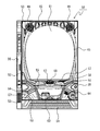
図1に示すように、弾球遊技機の一種であるパチンコ機50は、縦長の固定外郭保持枠をなす外枠51にて各部を保持する構造である。外枠51の左側上下には、ヒンジ53が設けられており、該ヒンジ53の他方側には図3に記載する内枠70が取り付けられており、内枠70は外枠51に対して開閉可能な構成になっている。前枠52には、板ガラス61が取り外し自在に設けられており、板ガラス61の奥には図2に記載する遊技盤1が内枠70に取り付けられている。
As shown in FIG. 1, a
前枠52の上側左右には、スピーカ66が設けられており、パチンコ機50から発生する遊技音が出力され、遊技者の趣向性を向上させる。また、遊技者の趣向性を向上させるために前枠52に遊技状態に応じて発光する枠側装飾ランプ65も複数設けられている。前枠52の下方には、上皿55と下皿63が一体に形成されている。下皿63の右側には発射ハンドル64が取り付けられており、該発射ハンドル64を時計回りに回動操作することによって発射装置(図示省略)が可動して、上皿55から供給された遊技球が遊技盤1に向けて発射される。
上皿55の上部ほぼ中央には、遊技者が操作可能な演出ボタンA67(本発明の有効期間変更手段の一部に相当)と演出ボタンB68(本発明の操作手段に相当)とを配置している。所定の擬似演出の実施中に報知された条件(演出ボタンA67の操作回数)を、所定期間中に達成することで有効期間Aが有効期間Bに変化し、有効期間A又は有効期間B中に演出ボタンB68を操作することで、各有効期間に応じた予告演出が後述する演出図柄表示装置6に表示される。
An effect button A67 (corresponding to a part of the effective period changing means of the present invention) and an effect button B68 (corresponding to the operating means of the present invention) which can be operated by the player are arranged at the substantially upper center of the
このパチンコ機50はいわゆるCR機であって、プリペイドカードの読み書き等を行うためのプリペイドカードユニット(CRユニット)56が付属しており、パチンコ機50は、貸出ボタン57、精算ボタン58及び残高表示器59を有するCR精算表示装置を備えている。また、本機は機外に賞球を払出す構成となっているが、所定数の遊技球を機内に封入し、発射した遊技球を遊技機内で回収して循環的に使用することで遊技を行う封入式遊技機としても何ら問題ない。さらに封入式遊技機とした場合は、後述する有効期限Aから有効期限Bに変更する条件を、遊技球の発射球数とすれば、検出スイッチの追加をしなくても実施可能となる。
The
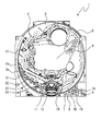
図2は、本実施例のパチンコ機の遊技盤1の正面図である。図2に示すように遊技盤1には、公知のガイドレール2a、2bによって囲まれた略円形の遊技領域3が設けられている。この遊技領域3には多数の遊技釘4が植設されている。
FIG. 2 is a front view of the
遊技領域3のほぼ中央部には、センターケース5が配されている。センターケース5は、公知のものと同様に、ワープ入口、ワープ通路、ステージ、演出図柄表示装置6(液晶表示装置であり演出図柄を表示する。)の画面を臨ませる窓等を備えている。センターケース5の下には、第1始動口11と第2始動口12とが配置され、センターケース5の左方には、ゲート17が配置されている。第2始動口12は開閉可能な翼片を供えた普通電動役物を備えており、この翼片が開放しないと遊技球は第2始動口12に入球できない構成となっている。
A
遊技領域の右下部には、複数個のLEDからなる普通図柄表示装置7と、普通図柄保留数表示装置8と、第1特別図柄保留数表示装置18と、第2特別図柄保留数表示装置19と、7セグメント表示装置からなる第1特別図柄表示装置9、第2特別図柄表示装置10とが配置されている。
In the lower right part of the game area, a normal
第2始動口12の下方にはアタッカー式の大入賞口14が配置されている。また、第1始動口11の左方には、第1左入賞口31、第2左入賞口32、第3左入賞口33及び第4左入賞口34が設けられている。なお、この第1左入賞口31、第2左入賞口32、第3左入賞口33、第4左入賞口34は、入球率が変化しない普通入賞口である。
An attacker type big winning
上記のように遊技盤1を構成することによって、普通図柄作動ゲート17に遊技球が入球(普通図柄作動スイッチ17a(図3参照)が遊技球を検出)すると、普通図柄表示装置で普通図柄が変動表示を開始し、所定時間後に停止した普通図柄の態様に応じて、後述する普通電役ソレノイド12b(図3参照)を駆動させる。普通電役ソレノイド12bが駆動すると、ほぼ同期して普通電動役物の羽根部材が開放して、第2始動口12への入球(第2始動口スイッチ12a(図3参照)の検出)が可能となるように構成されている。尚、本実施形態におけるパチンコ機では、普通電動役物の羽根部材が駆動する開放時間は、通常時は0.2秒(1回)、時短状態(開放延長状態)では1.8秒(2回)である。また、第2始動口12は、普通電動役物の羽根部材が駆動しなければ遊技球が入球不可能な構成となっている。
By configuring the
第1始動口11に遊技球が入球(第1始動口スイッチ11a(図3参照)が遊技球を検出)すると、第1特図表示装置において第1特別図柄が変動を開始し、所定時間後に停止する。また、第2始動口12である普通電動役物に遊技球が入球(第2特図始動スイッチ12a(図3参照)が遊技球を検出)すると、第2特図表示装置において第2特別図柄が変動表示を開始し、所定時間後に停止する。
When the game ball enters the first start port 11 (the first
第1特別図柄及び第2特別図柄の変動中は、演出図柄表示装置6において各々の特別図柄の変動に連動した演出態様を表示する。また、第1特別図柄と第2特別図柄は、第1始動口と第2始動口への入球順に関係なく、第2特別図柄の変動停止を優先して実施する。具体的には、第1特別図柄の保留記憶がある場合、第2特別図柄の変動が停止し且つ第2特別図柄保留記憶が無い状態となって、第1特別図柄保留記憶分の変動を開始する。
During the variation of the first special symbol and the second special symbol, the effect
第1特別図柄及び第2特別図柄の確定表示した態様に応じて後述する大入賞口ソレノイド14b(図3参照)が駆動する。大入賞口ソレノイド14bが駆動すると、ほぼ同期して大入賞口14の扉部材が開放し、大入賞口14への遊技球の入球(カウントスイッチ14a(図3参照)が遊技球を検出)が可能となるように構成されている。
A special
また、第1始動口11、第2始動口12に遊技球が入球したとき、又は普通図柄作動ゲート17を遊技球が通過したときに取得する当否乱数等の種々の乱数を、保留記憶として主制御装置50に格納(記憶)するとともに、第1始動口11及び第2始動口12への入球に起因する各種コマンドをサブ統合制御装置83(図3参照)に送信する処理を行う。以後、第1始動口11に遊技球が入球したときに格納される保留記憶を第1保留記憶、第2始動口12に遊技球が入球したときに格納される保留記憶を第2保留記憶、普通図柄作動ゲート17を遊技球が通過したときに格納される保留記憶を普図保留記憶として説明する。
In addition, various random numbers such as success / failure random numbers acquired when a game ball enters the
本実施形態においては、普図保留数表示装置、第1特図保留数表示装置、第2特図保留数表示装置による各々の点灯数の最大個数は4個(最大保留記憶数が4個)となっている。また、それぞれの保留記憶数が0であっても、第1始動口11、第2始動口12に遊技球が入球したとき、又は普通図柄作動ゲート17を遊技球が通過したときに取得される当否乱数等の種々の乱数は、最大値未満の記憶数がある場合と同様に主制御装置50に格納される。
In the present embodiment, the maximum number of lightings by the ordinary figure hold number display device, the first special figure hold number display device, and the second special figure hold number display device is 4 (the maximum hold memory number is 4). It has become. Even if the number of reserved memories is 0, it is acquired when a game ball enters the
第1特図始動スイッチ11a又は第2特図始動スイッチ12aが遊技球を検出し、その場合の第1保留記憶又は第2保留記憶の数が4個未満であれば、抽出した大当り判定用乱数、大当り図柄決定用乱数1、大当り図柄決定用乱数2、小当り図柄判定用乱数、リーチ決定用乱数、変動パターン決定用乱数を第1又は第2保留記憶として記憶領域に格納する。
If the first special
保留記憶された各種乱数は、当否判定処理(大当り判定)によって予め設定されている値との比較判定(本発明の判定に該当)が行われ、大当り判定用乱数の当否判定結果が大当り図柄決定用乱数の値に基づいて第1特図表示装置、第2特図表示装置、演出図柄表示装置6に表示される。
The various stored random numbers are subjected to a comparison determination (corresponding to the determination of the present invention) with a value set in advance by the determination process (hit determination), and the determination result of the determination result of the random number for determining the big hit is determined as a big hit symbol Is displayed on the first special figure display device, the second special figure display device, and the effect
尚、本実施形態におけるパチンコ機は確率変動機として構成されている。具体的に説明すると、本実施形態のパチンコ機による遊技は、大入賞口14を閉鎖した遊技と大入賞口14を開放する大当たり遊技とに大別され、大入賞口14を閉鎖した遊技には、大きく分類して、通常確率状態(以下、通常状態)と、該通常状態に比べて遊技者にとって有利な状態(大当りとなる確率が高く、大当りし易い)となる高確率状態(以下、確率変動状態とも記載)とが存在する。
In addition, the pachinko machine in this embodiment is comprised as a probability fluctuation machine. More specifically, the games by the pachinko machine according to the present embodiment are roughly classified into a game in which the
特別図柄は、確率変動図柄及び非確率変動図柄とからなり、確率変動状態は確率変動図柄での大当たり遊技終了後に移行可能に設定され、通常状態、確率変動状態のうち、いずれの遊技状態でも確率変動図柄で大当りすれば、大当り遊技終了後、確率変動状態に移行する。同様に通常状態は、非確率変動図柄での大当たり遊技終了後に移行可能に設定され、通常状態、確率変動状態のうち、いずれの遊技状態でも非確率変動図柄で大当たりすれば、大当たり遊技終了後、通常状態に移行する。 The special symbol consists of a probability variation symbol and a non-probability variation symbol, and the probability variation state is set so as to be able to transition after the jackpot game in the probability variation symbol, and the probability in any game state of the normal state and the probability variation state If a big hit is made with the fluctuating symbol, after the big hit game ends, the state shifts to a probability fluctuation state. Similarly, the normal state is set to be transitionable after the jackpot game with the non-stochastic variation symbol is finished, and if either of the normal state or the probability variation state is a big hit with the non-stochastic variation symbol, after the jackpot game ends, Transition to normal state.
通常状態に移行後は、規定回数(例えば、100回)だけ特別図柄及び普通図柄の変動時間が短縮され、かつ普通電動役物の開放延長機能が作動する時短状態となる。特別図柄及び普通図柄の変動時間(変動開始から結果が表示されるまでの時間)が短縮されると、一定時間内に変動表示が行なわれる回数が増大される。 After the transition to the normal state, the variation time of the special symbol and the normal symbol is shortened by a specified number of times (for example, 100 times), and the short state is reached when the opening extension function of the ordinary electric accessory is activated. If the variation time of special symbols and normal symbols (the time from the start of variation until the result is displayed) is shortened, the number of times the variation display is performed within a certain time is increased.
具体的には、本実施形態の時短状態では、特別図柄の変動時間の短縮とともに、普通図柄表示装置に表示される普通図柄の時間短縮も行われるが、この普通図柄の変動表示を短縮させることで、一定時間内で多数回普通図柄の確定表示を行う。従って、一定時間内での普通図柄が当りとなる回数が増大し、これにより普通電動役物の作動回数も増大する。また、普通電動役物の開放時間が長くなるように設定されている(開放延長機能)ので、多数の遊技球が入賞し易くなる。このように多数の遊技球が入賞し易くなることにより、特別図柄の変動表示回数が更に増大されるとともに、普通電動役物入賞で得る賞球により、遊技者の持ち玉が減り難くなり、有利な遊技を行うことができる。 Specifically, in the short time state of the present embodiment, the special symbol display time is shortened along with the special symbol variation time, but the normal symbol variation display is shortened. Then, the regular symbol is confirmed and displayed many times within a certain time. Therefore, the number of times that the normal symbol hits within a certain time increases, and the number of times of operation of the ordinary electric accessory also increases. In addition, since the opening time of the ordinary electric accessory is set to be long (opening extension function), it becomes easy to win a large number of game balls. By making it easy for a large number of game balls to win in this way, the number of times of special symbol variation display is further increased. Can play a variety of games.
尚、確率変動状態では、時短状態と同様に特別図柄及び普通図柄の変動時間が短縮され、普通電動役物の開放延長機能が作動する。各種図柄の短縮と普通電動役物開放延長機能に関わる設定は時短状態と同一であるが、確率変動状態は時短状態に加えて特別図柄の大当り確率が高くなる(大当りし易い状態)ため、更に遊技者に有利な遊技状態となる。 In the probability variation state, the variation time of the special symbol and the normal symbol is shortened similarly to the time-short state, and the opening extension function of the ordinary electric accessory is activated. The settings related to the shortening of various symbols and the function to open and extend the normal electric utility are the same as the short-time state, but the probability variation state increases the probability of hitting a special symbol in addition to the short-time state. The gaming state is advantageous to the player.
図3は、パチンコ機50の裏面を示し、前述した遊技盤1を脱着可能に取り付ける内枠70が前述した外枠51に収納されている。この内枠70には、上方から、球タンク71、タンクレール72及び払出装置73が設けられている。この構成により、遊技盤1上の入賞口に遊技球が入球すれば球タンク71からタンクレール72を介して所定個数の遊技球を払出装置73により前述した上皿55に排出することができる。また、パチンコ機50の裏側には、主制御装置80、払出制御装置81、演出図柄制御装置82、サブ統合制御装置83、発射制御装置、電源基板85が設けられている。なお、演出図柄制御装置82、サブ統合制御装置83が、本発明のサブ制御装置に相当する。
FIG. 3 shows the back surface of the
主制御装置80、演出図柄制御装置82、サブ統合制御装置83は遊技盤1に設けられており、払出制御装置81、発射制御装置、電源基板85が内枠70に設けられている。なお、図3では、発射制御装置が描かれていないが、発射制御装置は払出制御装置81の下(裏側)に設けられている。また、球タンク71の右側には、外部接続端子78が設けられており、この外部接続端子78より、遊技状態や遊技結果を示す信号が図示しないホールコンピュータに送られる。なお、従来はホールコンピュータへ信号を送信するための外部接続端子78には、盤用(遊技盤側から出力される信号をホールコンピュータへ出力するための端子)と枠用(枠側(前枠52、内枠70、外枠51)から出力される信号をホールコンピュータへ出力するための端子)の2種類を用いているが、本実施例では、一つの外部接続端子78を介してホールコンピュータへ遊技状態や遊技結果を示す信号を送信している。
The
図4は、パチンコ機50の電気的構成を示すブロック図となり、主制御装置80を中心にして構成されている。なお、このブロック図には、単に信号を中継するだけのためのいわゆる中継基板及び電源回路等は記載していない。また、詳細な図示は省略するが、主制御装置80、払出制御装置81、演出図柄制御装置82、サブ統合制御装置83のいずれもCPU、ROM、RAM、入力ポート、出力ポート等を備えているが、本実施例では発射制御装置84にはCPU、ROM、RAMは設けられていない。しかし、これに限るわけではなく、発射制御装置84にCPU、ROM、RAM等を設けてもよい。
FIG. 4 is a block diagram showing an electrical configuration of the
主制御装置80には、第1始動口11に入球した遊技球を検出する第1始動口スイッチ11a、第2始動口12に入球した遊技球を検出する第2始動口スイッチ12a、普通図柄を作動させるゲート17に進入した遊技球を検出する普通図柄作動スイッチ17a、大入賞口14に入球した遊技球を計数するためのカウントスイッチ14a、第1左入賞口31、第2左入賞口32、第3左入賞口33、第4左入賞口34に入球した遊技球を検出する左入賞口スイッチ31a等の検出信号が入力される。
The
主制御装置80は搭載しているプログラムに従って動作して、上述の検出信号などに基づいて遊技の進行に関わる各種のコマンド(本発明の主制御装置から送信される信号に相当)を生成して払出制御装置81及びサブ統合制御装置83に出力する。また主制御装置80は、図柄表示装置中継端子板90を介して接続されている第1特別図柄表示装置9、第2特別図柄表示装置10及び普通図柄表示装置7の表示、第1特別図柄保留数表示装置18、第2特別図柄保留数表示装置19、普通図柄保留数表示装置8の点灯を制御する。
The
更に、主制御装置80は、大入賞口ソレノイド14bを制御することで大入賞口14の開閉を制御し、普通電動役物ソレノイド(図4では普電役物ソレノイドと表記)12bを制御することで第2始動口12となる普通電動役物の開閉動作を制御する。主制御装置80からの出力信号は試験信号端子にも出力される他、図柄変動や大当り(特別遊技ともいう)等の管理用の信号が外部接続端子78に出力されてホールコンピュータ87に送られる。
Further, the
主制御装置80と払出制御装置81とは双方向通信が行われ、払出制御装置81は、主制御装置80から送られてくるコマンドに応じて払出モータ20を制御して賞球を払い出す。本実施例においては、賞球として払い出される遊技球を計数するための払出スイッチ21の検出信号は払出制御装置81に入力され、払出制御装置81で賞球の計数が行われる構成を用いる。この他にも主制御装置80と払出制御装置81に払出スイッチ21の検出信号が入力され、主制御装置80と払出制御装置81の双方で賞球の計数を行う構成を用いることも考えられる。
The
なお、払出制御装置81はガラス枠開放スイッチ35、内枠開放スイッチ36、満杯スイッチ22、球切れスイッチ23からの信号が入力され、満杯スイッチ22により下皿63が満タンであることを示す信号が入力された場合及び球切れスイッチ23により球タンクに遊技球が少ないあるいは無いことを示す信号が入力されると払出モータ20を停止させ、賞球の払出動作を停止させる。なお、満杯スイッチ22、球切れスイッチ23も、その状態が解消されるまで信号を出力し続ける構成になっており、払出制御装置81は、その信号が出力されなくなることに起因して払出モータ20の駆動を再開させる。
The
また、払出制御装置81はCRユニット端子板24を介してプリペイドカードユニットと交信することで払出モータ20を作動させ、貸し球を排出する。払出された貸し球は払出スイッチ21に検出され、検出信号は払出制御装置81に入力される。なお、CRユニット端子板24は精算表示基板25とも双方向通信可能に接続されており、精算表示基板25には、遊技球の貸出しを要求するための球貸ボタン、精算を要求するための返却ボタン、残高表示器が接続されている。
Also, the
また、払出制御装置81は、外部接続端子78を介して賞球に関する情報、枠(内枠、前枠)の開閉状態を示す情報などをホールコンピュータに送信するほか、発射制御装置84に対して発射停止信号を送信する。なお本実施例では遊技球を払い出す構成であるが、入賞等に応じて発生した遊技球を払い出さずに記憶する封入式の構成にしても良い。
Also, the
発射制御装置84は発射モータ30を制御して、遊技領域3に遊技球を発射させる。なお、発射制御装置84には払出制御装置81以外に発射ハンドルからの回動量信号、タッチスイッチ28からのタッチ信号、発射停止スイッチ29から発射停止信号が入力される。回動量信号は、遊技者が発射ハンドルを操作することで出力され、タッチ信号は遊技者が発射ハンドルを触ることで出力され、発射停止スイッチ信号は、遊技者が発射停止スイッチ29を押すことで出力される。なお、タッチ信号が発射制御装置84に入力されていなければ、遊技球は発射できないほか、発射停止スイッチ信号が入力されているときには、遊技者が発射ハンドルを触っていても遊技球は発射できないようになっている。
The
本願発明のサブ制御装置に該当するサブ統合制御装置83は、主制御装置80から送信されてくるデータ及びコマンドを受信し、それらを演出表示制御用、音制御用及びランプ制御用のデータに振り分けて、演出表示制御用のコマンド等は演出図柄制御装置82に送信し、音制御用及びランプ制御用は自身に含まれている各制御部位(音声制御装置及びランプ制御装置としての機能部)に分配する。そして、音声制御装置としての機能部は、音声制御用のデータに基づいて音LSIを作動させることによってスピーカからの音声出力を制御し、ランプ制御装置としての機能部はランプ制御用のデータに基づいてランプドライバを作動させることによって各種LED、ランプ26を制御する。
The sub integrated
また、サブ統合制御装置83には、演出ボタンA67の操作を検出する演出ボタンAスイッチ67a、演出ボタンB68の操作を検出する演出ボタンBスイッチ68aが接続されており、遊技者が演出ボタンA67、演出ボタンB68を操作した際には、その信号がサブ統合制御装置83に入力される。なお、演出ボタンA67は本発明の有効期間変更手段の一部、演出ボタンB68が操作手段に相当する。
The
演出図柄制御装置82は、サブ統合制御装置83から受信したデータ及びコマンド(共に主制御装置80から送信されてきたものとサブ統合制御装置83が主制御装置80からの入力及び演出ボタンA67、演出ボタンB68の入力に基づいて生成したものとがある)に基づく制御を行い、擬似図柄等の演出画像を演出図柄表示装置6の画面6aに表示させる。尚、サブ統合制御装置83と主制御装置80とは間に演出中継端子板65を介した主制御装置80からサブ統合制御装置83への一方向通信回路として構成され、サブ統合制御装置83と演出図柄制御装置82とはサブ統合制御装置83から演出図柄制御装置82への一方向通信回路として構成されている。
The effect
次に、図5を用いて、主制御装置80が実行するメインルーチンを説明する。メインルーチンは、約2ms毎のハード割り込みにより定期的に実行される。本実施形態では、S10〜S65までの1回だけ実行される処理を「本処理」と称し、この本処理を実行して余った時間内に時間の許す限り繰り返し実行されるS70の処理を「残余処理」と称する。「本処理」は上記割り込みにより定期的に実行されることになる。
Next, a main routine executed by the
マイコンによるハード割り込みが実行されると、まず正常割り込みであるか否かが判断される(S10)。この判断処理は、メモリとしてのRAMの所定領域の値が所定値であるか否かを判断することにより行われ、マイコンにより実行される処理が本処理に移行したとき、通常の処理を実行して良いのか否かを判断するためのものである。正常割り込みでない場合としては、電源投入時又はノイズ等によるマイコンの暴走等が考えられるが、マイコンの暴走は近年の技術の向上によりほとんど無いものと考えて良いので、ほとんどが電源投入時である。電源投入時にはRAMの所定領域の値が所定値と異なる値となっている。 When a hardware interrupt is executed by the microcomputer, it is first determined whether or not the interrupt is a normal interrupt (S10). This determination process is performed by determining whether or not the value of a predetermined area of the RAM as a memory is a predetermined value. When the process executed by the microcomputer shifts to this process, the normal process is executed. It is for judging whether it is okay. As a case where the interruption is not normal, microcomputer runaway due to noise or the like may be considered when power is turned on, but microcomputer runaway may be considered to be almost impossible due to recent technological improvements, and is mostly at power on. When the power is turned on, the value of the predetermined area of the RAM is different from the predetermined value.
S10が否定判定、即ち、正常割り込みでないと判断されると(S10:no)、初期設定(例えば前記メモリの所定領域への所定値を書き込み、特別図柄及び普通図柄を初期図柄とする等のメモリの作業領域への各初期値の書き込み等)が為され(S15)、残余処理(S70)に移行する。 When S10 is negative, that is, when it is determined that the interrupt is not normal (S10: no), initial setting (for example, a predetermined value is written to a predetermined area of the memory and a special symbol and a normal symbol are used as an initial symbol, etc.) The initial values are written into the work area (S15), etc.) (S15), and the process proceeds to the remaining process (S70).
正常割り込みとの肯定判断がなされると(S10:yes)、初期値乱数更新処理が実行される(S20)。この処理は、初期値乱数の値についてこの処理を実行する毎に+1するインクリメント処理であり、この処理実行前の初期値乱数の値に+1するが、この処理を実行する前の乱数値が最大値である「3966」のときには次回の処理で初めの値である「0」に戻り、「0」〜「3966」までの3967個の整数を繰り返し昇順に作成する。 If a positive determination is made that the interrupt is normal (S10: yes), an initial value random number update process is executed (S20). This process is an increment process that increments the initial random number value by 1 each time this process is executed. The initial random number value before this process is incremented by +1, but the random number value before this process is executed is the maximum. When the value is “3966”, it returns to the initial value “0” in the next processing, and 3967 integers from “0” to “3966” are repeatedly generated in ascending order.
S20に続く大当り決定用乱数更新処理(S25)は、初期値乱数更新処理と同様に処理を実行する毎に+1するインクリメント処理であり、最大値である「3966」のときは次回の処理で初めの値である「0」に戻り、「0」〜「3966」までの3967個の整数を繰り返し昇順に作成する。なお、大当り決定用乱数の最初の値は、初期値乱数設定処理で設定された値となる。例えば、この値が250であったとすると、大当り決定用乱数は「250」「251」「252」・・・「3966」「0」「1」・・・と更新されていく。 The big hit determination random number update process (S25) following S20 is an increment process that is incremented by 1 each time the process is executed, similar to the initial value random number update process. When the maximum value is "3966", the next process starts. Is returned to “0”, and 3967 integers from “0” to “3966” are repeatedly generated in ascending order. Note that the initial value of the jackpot determination random number is the value set in the initial value random number setting process. For example, if this value is 250, the jackpot determination random number is updated as “250” “251” “252”... “3966” “0” “1”.
なお、大当り決定用乱数が1巡(3967回、更新されること)すると、そのときの前記初期値乱数の値を大当り決定用乱数の初期値にし、大当り決定用乱数は、その初期値から+1するインクリメント処理を行う。そして、再び大当り決定用乱数が1巡すると、その時の初期値乱数の値を大当り決定用乱数の初期値にする動作を行なう。つまり、この一連の動作を繰り返し続けることになる。前述の例では大当り決定用乱数が「249」になると1巡であるから、「249」の次は前記初期値乱数の値となる。仮に初期値乱数の値が「87」だったとすると、「249」「87」「88」・・・「3966」「0」「1」・・・「86」と変化していき、「86」の次は新たな前記初期値乱数の値となる。 When the big hit determination random number is updated once (3967 times), the initial random number value at that time is used as the initial value of the big hit determination random number, and the big hit determination random number is +1 from the initial value. Increment processing is performed. Then, when the big hit determining random number makes one round again, the initial value random number at that time is changed to the initial value of the big hit determining random number. That is, this series of operations is repeated. In the above example, when the big hit determination random number reaches “249”, it is one round, so the next value after “249” is the value of the initial value random number. If the value of the initial random number is “87”, “249” “87” “88”... “3966” “0” “1”. Next to is a new initial random number value.
大当り図柄決定用乱数1更新処理(S30)は「0」〜「99」の100個の整数を繰り返し作成するカウンタとして構成され、本処理毎に+1され最大値を超えると初めの値である「0」に戻る。大当り図柄決定用乱数2更新処理(S31)は「0」〜「49」の50個の整数を繰り返し作成するカウンタとして構成され、本処理毎に+1され最大値を超えると初めの値である「0」に戻る。小当り図柄判定用乱数更新処理(S33)は「0」〜「149」の150個の整数を繰り返し作成するカウンタとして構成され、本処理毎に+1され最大値を超えると初めの値である「0」に戻る。
The big hit symbol determination
S33に続く当り決定用乱数更新処理(S35)は、「0」〜「996」の997個の整数を繰り返し作成するカウンタとして構成され、本処理毎で+1され最大値を超えると初めの値である「0」に戻る。なお、当選することとなる値は通常確率状態では31〜40、高確率状態では31〜996である。なお、この当り決定用乱数更新処理は普通図柄の抽選に使用し、その他の初期値乱数、大当り決定用乱数、大当り図柄決定用乱数1、大当り図柄決定用乱数2、小当り図柄判定用乱数、リーチ判定用乱数、変動パターン決定用乱数は特別図柄の抽選に使用する。
The hit-decision random number update process (S35) following S33 is configured as a counter that repeatedly creates 997 integers from “0” to “996”, and is incremented by 1 every time this process is exceeded. Return to a certain “0”. The values to be won are 31 to 40 in the normal probability state and 31 to 996 in the high probability state. The winning determination random number update process is used for lottery of normal symbols, and other initial value random numbers, big hit determining random numbers, big hit symbol determining
リーチ判定用乱数更新処理(S40)は、「0」〜「228」の229個の整数を繰り返し作成するカウンタとして構成され、本処理毎で+1され最大値を超えると初めの値である「0」に戻る。なお、通常確率状態時で変動時間短縮機能未作動時にリーチとなる値の数は21で、値は「0」〜「20」であり、通常確率状態時で変動時間短縮機能作動時にリーチとなる値の数は5で、値は「0」〜「4」であり、高確率状態時にリーチとなる値の数は6で、値は「0」〜「5」である。 The reach determination random number update process (S40) is configured as a counter that repeatedly generates 229 integers from “0” to “228”, and is incremented by +1 for each process and the initial value is “0”. Return to. In the normal probability state, the number of values that reach when the variable time reduction function is not activated is 21, and the values are “0” to “20”, and reach when the variable time reduction function is activated in the normal probability state. The number of values is 5, the values are “0” to “4”, the number of values that reach in the high probability state is 6, and the values are “0” to “5”.
変動パターン決定用乱数更新処理(S45)は、「0」〜「1020」の1021個の整数を繰り返し作成するカウンタとして構成され、本処理毎で+1され最大値を超えると初めの値である「0」に戻る。 The variation pattern determination random number update process (S45) is configured as a counter that repeatedly creates 1021 integers from “0” to “1020”, and is incremented by 1 for each process and is the first value when the maximum value is exceeded. Return to "0".
続く入賞確認処理(S50)では、第1始動口11、第2始動口12の入賞の確認及びパチンコ機50に設けられ主制御装置80に接続された各スイッチ類の入力処理が実行される。本実施例では、遊技球が第1始動口11、第2始動口12に入賞すると大当り決定用乱数、大当り図柄決定用乱数1、大当り図柄決定用乱数2、変動パターン決定用乱数、リーチ判定用乱数など複数の乱数を取得されるのだが、保留記憶できる数を第1始動口11と第2始動口12でそれぞれ4個までとしており、保留記憶が満タンである4個のときに遊技球が第1始動口11又は第2始動口12に入賞しても賞球が払出されるだけで、前記複数の乱数は保留記憶されない構成になっている。
In the subsequent winning confirmation process (S50), confirmation of winning in the
続いて、大当りか否かを判定する条件成立判定手段としての当否判定処理(S55)を行う。この当否判定処理(S55)が終了すると、続いて画像出力処理等の各出力処理(S60)が実行される。各出力処理(S60)では、遊技の進行に応じて主制御装置80は演出図柄制御装置82、払出制御装置81、発射制御装置84、サブ統合制御装置83、大入賞口ソレノイド14b等に対して各々出力処理を実行する。即ち、入賞確認処理(S50)により遊技盤1上の各入賞口に遊技球の入賞があることが検知されたときには、賞球としての遊技球を払い出すべく払出制御装置81に賞球データを出力する処理を、遊技状態に対応したサウンドデータをサブ統合制御装置83に出力する処理を、パチンコ機50に異常があるときにはエラー中であることを報知すべく演出図柄制御装置82にエラー信号を出力する処理を各々実行する。
Subsequently, a success / failure determination process (S55) is performed as condition establishment determination means for determining whether or not a big hit. When this success / failure determination process (S55) ends, each output process (S60) such as an image output process is subsequently executed. In each output process (S60), as the game progresses, the
続く不正監視処理(S65)は、普通入賞口(第1左入賞口31、第2左入賞口32、第3左入賞口33、第4左入賞口34)に対する不正が行われていないか監視する処理であり、所定時間内における入賞口への遊技球の入球が予め決定された規定数よりも多いか否かを判断して、多かった場合には不正と判断され、その旨を報知する処理である。つまり、不正判断手段は、主制御装置80に設けている。
In the subsequent fraud monitoring process (S65), it is monitored whether or not fraud is performed on the normal winning award (the first
本処理に続く前述の残余処理は、初期値乱数更新処理(S70)から構成されるが、前述したS20と全く同じ処理である。この処理は無限ループを形成し、次の割り込みが実行されるまで時間の許される限り繰り返し実行される。前述したS10〜S65までの本処理を実行するのに必要とされる時間は、大当り処理を実行するか否か、特別図柄の表示態様の相違等により割り込み毎に異なる。この結果、残余処理を実行する回数も割り込み毎に異なり、図7に示された割り込み処理が1回実行されることにより初期値乱数に更新される値も一律ではなくなる。これにより、初期値乱数が大当り決定用乱数と同期する可能性は極めて小さくなる。大当り決定用乱数が1巡したときの、初期値乱数の値(0〜3966の3967通り)が、同程度に発生するとすれば、同期する確率はわずか1/3967である。また、前述した当り決定用乱数更新処理(S35)も残余処理内において実行するよう構成しても良い。 The above-described remaining process following this process is composed of the initial value random number update process (S70), but is exactly the same process as S20 described above. This process forms an infinite loop and is repeated as long as time is allowed until the next interrupt is executed. The time required to execute this processing from S10 to S65 described above differs for each interrupt depending on whether or not to execute the jackpot processing, the difference in the display mode of special symbols, and the like. As a result, the number of times the remaining process is executed is different for each interrupt, and the value updated to the initial random number is not uniform when the interrupt process shown in FIG. 7 is executed once. Thereby, the possibility that the initial value random number is synchronized with the big hit determination random number becomes extremely small. If the value of the initial random number (3967 from 0 to 3966) when the big hit determination random number is made one round, the probability of synchronization is only 1/3967. The hit determination random number update process (S35) described above may also be executed in the remaining process.
次に図6に示したフローチャートを用いて、主制御装置80が実行する始動入賞処理を説明する。始動入賞処理は、第1始動口11、第2始動口12に遊技球が入球したとき、又は普通図柄作動ゲート17を遊技球が通過したときに取得する当否乱数等の種々の乱数を、保留記憶として主制御装置80に格納(記憶)するとともに、記憶した乱数が予め設定された値か否かを後述する当否判定を実施する以前に確認する処理を行い、第1始動口11及び第2始動口12への入球に起因する各種コマンドをサブ統合制御装置83に送信する処理となる。以後、第1始動口11に遊技球が入球したときに格納される保留記憶を第1保留記憶、第2始動口12に遊技球が入球したときに格納される保留記憶を第2保留記憶、普通図柄始動ゲート17を遊技球が通過したときに格納される保留記憶を普図保留記憶として説明する。
Next, the start winning process executed by the
本実施形態においては、普通図柄保留数表示装置8、第1特図保留数表示装置18、第2特図保留数表示装置19による各々の点灯数の最大個数は4個(最大保留記憶数が4個)となっているが、これに限るわけではなく、例えばそれぞれの最大記憶個数が8個であってもよい。また、それぞれの保留記憶数が0であっても、第1始動口11、第2始動口12に遊技球が入球したとき、又は普通図柄作動ゲート17を遊技球が通過したときに取得される当否乱数等の種々の乱数は、最大値未満の記憶数がある場合と同様に主制御装置80に格納される。
In the present embodiment, the maximum number of lighting by each of the normal symbol hold
始動入賞処理を開始すると、第1始動口スイッチ11aが遊技球を検出したか否か判定する(S100)。否定判定なら(S100:no)S130に進み、肯定判定なら(S100:yes)、主制御装置80に格納されている第1保留記憶の数が上限値(=4個)未満か否か判定する(S105)。否定判定なら(S105:no)S130に進み、肯定判定であれば(S105:yes)、抽出した大当り判定用乱数、大当り図柄決定用乱数1、大当り図柄決定用乱数2、小当り図柄判定用乱数、リーチ決定用乱数、変動パターン決定用乱数を第1保留記憶として記憶し第1保留記憶の数を示す第1保留記憶カウンタに1を加算する(S110)。
When the start winning process is started, it is determined whether or not the first
S110に続いては、記憶した第1保留記憶の先読判定を行う(S115)。具体的には、大当り判定用乱数の値が大当りを生起する値か否かを確認し、大当り値なら大当り図柄の種類を確認する。大当り判定がハズレなら、小当りを生起する値か否かを確認し、ハズレならリーチ決定用乱数がスーパーリーチとなる値か否かを確認する。スーパーリーチでなければ、リーチとなる値か否かを確認し、変動パターン決定用乱数の値から変動時間を確認する。上記判定を行うことによって、記憶した乱数値が、遊技者が大当りの期待が持てる特定の値か否か(はずれでも大当りを期待させる演出が可能な否か)を判定する。 Subsequent to S110, the prefetch determination of the stored first reserved memory is performed (S115). Specifically, it is confirmed whether or not the value of the random number for determining the big hit is a value that causes the big hit, and if the big hit value, the type of the big hit symbol is checked. If the big hit determination is a loss, it is checked whether the value is a value that causes a small hit, and if the big hit is lost, it is checked whether the reach determination random number is a value that is a super reach. If it is not a super reach, it is confirmed whether or not it is a reach value, and the variation time is confirmed from the value of the random number for determining the variation pattern. By performing the above determination, it is determined whether or not the stored random number value is a specific value that the player can expect to win a jackpot (whether or not an effect that can expect a jackpot is possible even if the player loses).
続いて、S115の判定結果から第1先読判定コマンドを生成してサブ統合制御装置53に送信し(S120)、S110で加算した第1保留記憶カウンタの値を示す第1保留数指示コマンドをサブ統合制御装置83に送信する(S125)。 Subsequently, a first prefetch determination command is generated from the determination result of S115 and transmitted to the sub integrated control device 53 (S120), and a first hold number instruction command indicating the value of the first hold storage counter added in S110 is issued. The data is transmitted to the sub integrated control device 83 (S125).
S125の処理、又はS100、S105の否定判定(S100:no、S105:no)に続いては、第2始動口スイッチ12aが遊技球を検出したか否か判定する(S130)。否定判定なら(S130:no)S160に進み、肯定判定なら(S130:yes)、主制御装置80に格納されている第2保留記憶の数が上限値(=4個)未満か否か判定する(S135)。否定判定なら(S135:no)S160に進み、肯定判定であれば(S135:yes)、抽出した大当り判定用乱数、大当り図柄決定用乱数1、大当り図柄決定用乱数2、小当り図柄判定用乱数、リーチ決定用乱数、変動パターン決定用乱数を第2保留記憶として記憶し第2保留記憶数を示す第2保留記憶カウンタに1を加算し(S140)、S110と同様に記憶した第2保留記憶の先読判定を行う(S145)。
Following the processing of S125 or the negative determinations of S100 and S105 (S100: no, S105: no), it is determined whether or not the second start port switch 12a has detected a game ball (S130). If a negative determination is made (S130: no), the process proceeds to S160, and if an affirmative determination is made (S130: yes), it is determined whether or not the number of second reserved memories stored in the
続いて、S145の判定結果から第2先読判定コマンドを生成しサブ統合制御装置53に送信し(S150)、S140で加算した第2保留記憶カウンタの値を示す第2保留数指示コマンドをサブ統合制御装置83に送信して(S155)、S160に進む。 Subsequently, a second prefetch determination command is generated from the determination result of S145 and transmitted to the sub integrated control device 53 (S150), and a second hold number instruction command indicating the value of the second hold storage counter added in S140 is sub The data is transmitted to the integrated control device 83 (S155), and the process proceeds to S160.
S160では、普通図柄作動スイッチ17aが遊技球を検出したか否か判定する(S160)。否定判定なら(S160:no)リターンに抜け、肯定判定なら(S160:yes)、主制御装置80に格納されている普図保留記憶数が上限値(=4個)未満か否か判定する(S165)。否定判定なら(S165:no)リターンに抜け、肯定判定であれば(S165:yes)、抽出した当り判定用乱数と当り図柄決定用乱数とを普図保留記憶として記憶し、普図保留記憶数を示す普図保留記憶カウンタに1を加算し(S170)、加算した普図保留記憶カウンタの値を示す普図保留記憶数指示コマンドをサブ統合制御装置83に送信し(S175)、リターンする。
In S160, it is determined whether or not the normal
サブ統合制御装置83は第1及び第2保留記憶数指示コマンドを受信すると、受信したコマンドが示す保留記憶数に応じて演出図柄表示装置6上で表示する各保留記憶数を変化させる指示信号を演出図柄制御装置82に送信する。また、本実施例では、演出図柄表示装置6上では普通図柄の保留記憶数表示は行わないが、普図保留記憶数指示コマンドの受信に応じて表示する構成としてもよいし、普図保留記憶数指示コマンド自体を送信しない構成としてもよい。また、普図の先読判定を実施し判定結果をサブ統合制御装置に送信する構成も考えられる。これにより、普通電動役物(第2始動口12)の開放を期待させる先読予告の実施が可能となる。
When the sub integrated
次に、図7に示したフローチャートを用いて主制御装置80が行う当否判定処理を説明する。この処理は、第1始動口スイッチ11a又は第2始動口スイッチ12aでの遊技球の検出に起因して抽出された乱数値に基づいて特別遊技を実行するか否かを判定(始動口への遊技球の入球に起因して抽出した乱数値に基づいて遊技者に有利な大当り遊技を発生させるか否かを判定)する処理となる。
Next, the success / failure determination process performed by the
当否判定処理を開始すると、特図の始動条件が成立しているか否か判定する(S200)。この判定処理では、大当り遊技中でないこと、第1特別図柄及び第2特別図柄が変動中又は確定表示中でないことを確認する。否定判定なら(S200:no)リターンに抜け、肯定判定なら(S200:yes)、第2保留記憶が有るか否か判定する(S205)。肯定判定なら(S205:yes)、S215に進み、否定判定なら(S205:no)第1保留記憶が有るか否か判定する(S210)。否定判定なら(S210:no)リターンに抜け、肯定判定なら(S210:yes)、S215に進む。S205とS210の判定順により、第2保留記憶の当否判定を優先して実施する構成となっている。尚、本実施例では、特別図柄が複数(第1特別図柄と第2特別図柄)の構成となっているが、特別図柄を1つとした構成であってもその効果に何ら変わりはない。 When the hit / no-go determination process is started, it is determined whether or not a special drawing start condition is satisfied (S200). In this determination process, it is confirmed that the big hit game is not being played, and that the first special symbol and the second special symbol are not changing or being displayed in a fixed manner. If the determination is negative (S200: no), the process returns to the return. If the determination is affirmative (S200: yes), it is determined whether there is a second reserved memory (S205). If the determination is affirmative (S205: yes), the process proceeds to S215. If the determination is negative (S205: no), it is determined whether or not there is a first reserved memory (S210). If the determination is negative (S210: no), the process returns to the return. If the determination is affirmative (S210: yes), the process proceeds to S215. According to the determination order of S205 and S210, the determination of whether or not the second reserved storage is appropriate is performed with priority. In this embodiment, there are a plurality of special symbols (a first special symbol and a second special symbol). However, even if the configuration has one special symbol, the effect is not changed.
S215では確変フラグの値が0か否か判定する(S215)。確変フラグは、主制御装置80が記憶する値であり、値が「0」のときは、大当り確率が通常遊技状態中(通常確率)であることを、値が「1」のときは、確変遊技状態中(高確率)であることを主制御装置80が判断するための値である。肯定判定なら(S215:yes)S220に進み、否定判定なら(S215:no)高確率中の処理に進む。高確率中の処理は、大当り確率のみが異なる処理となるため説明は割愛する。
In S215, it is determined whether or not the value of the probability variation flag is 0 (S215). The probability change flag is a value stored in the
S220では、保留記憶のシフト処理を行い(S220)、これにより最も古い保留記憶を当否判定の対象とするとともに、保留記憶数を示す保留記憶カウンタから1を減算する。 In S220, a hold memory shift process is performed (S220), whereby the oldest hold memory is determined as a target of the determination, and 1 is subtracted from the hold memory counter indicating the number of hold memories.
続く、大当り判定用乱数比較処理(S225)では、当否判定の対象とした保留記憶の大当り判定用乱数値と予め設定された当否判定テーブルとを比較して、判定対象の乱数値が当否判定テーブル内の判定値と一致するか比較する。当否判定テーブルは通常確率(低確率1/300)用と高確率(1/30)用の2種類のテーブルが設定してあり、当否判定時の遊技状態が通常遊技(確変フラグ「0」)であれば通常確率用の当否判定テーブルを用いて比較し、高確率の遊技状態(確変フラグ「1」)であれば高確率用の当否判定テーブルを用いて比較する。
In the subsequent jackpot determination random number comparison process (S225), the determination is made by comparing the jackpot determination random number value in the reserved storage that is the target of the determination with the preset determination table. Compared with the judgment value in. Two types of tables for normal probability (
続くS230の処理では、大当り判定用乱数の比較処理(S225)の結果が大当り(判定値と同一)であるか否か判定する(本実施例では1/300)。肯定判定なら(S230:yes)、図柄モード設定処理を行う(S235)。図柄モード設定処理では、当否判定の対象とした保留記憶の種類(第1保留記憶又は第2保留記憶)と、判定対象となる保留記憶の大当り図柄決定用乱数1に基づいて、大当り遊技の内容と大当り遊技終了後の遊技状態を決定する図柄モードを設定する(S235)。続いて、設定した図柄モードの種類と判定対象となる保留記憶の大当り図柄決定用乱数2に基づいて大当り図柄選択処理を行う(S240)。これは、図柄モードの設定によって決定した大当りの種類(大当り遊技の内容と大当り遊技終了後の遊技状態)を大当り図柄によって報知するために、図柄モードの種類毎に設定された図柄郡の中から表示する図柄を決定する処理となる。
In the subsequent processing of S230, it is determined whether or not the result of the big hit determination random number comparison processing (S225) is a big hit (same as the determination value) (1/300 in this embodiment). If it is affirmation determination (S230: yes), a symbol mode setting process will be performed (S235). In the symbol mode setting process, the content of the jackpot game is determined based on the type of the hold memory (first hold memory or the second hold memory) that is the target of the success / failure determination and the jackpot symbol determination
次にS235で設定した図柄モードに基づいてモードバッファ設定処理を行う(S245)。モードバッファは当否判定時に決定した大当り遊技終了後の遊技状態の内容を、該遊技状態を設定する大当り遊技終了時まで記憶する装置である(大当り遊技中は遊技状態を設定する確変フラグ及び時短フラグをクリアする必要があるため)。モードバッファとしては、具体的な遊技内容(確変機能および開放延長機能(時短機能)の作動とその作動回数)は記憶せず、複数種類の具体的な遊技内容のそれぞれに対応した値を記憶する構成となっている。 Next, mode buffer setting processing is performed based on the symbol mode set in S235 (S245). The mode buffer is a device that stores the contents of the gaming state after the end of the big hit game determined at the time of determination of the success / failure until the end of the big hit game that sets the gaming state (the probability change flag and the short time flag that set the gaming state during the big hit game) Because it is necessary to clear). The mode buffer does not store the specific game contents (activities of the probability changing function and release extension function (time reduction function) and the number of times of operation), but stores values corresponding to each of a plurality of types of specific game contents. It has a configuration.
次に、S235で設定した図柄モードに基づいて大当り遊技の内容となる大入賞口の開放パターン設定処理を行い(S250)、当否判定の対象とした保留記憶のリーチ決定用乱数および変動パターン決定用乱数に基づいて、第1特別図柄表示装置9又は第2特別図柄表示装置10、及び演出図柄表示装置6に表示する図柄の変動時間となる変動パターンを、変動パターン選択テーブルから選択する(S255)。
Next, based on the symbol mode set in S235, the winning pattern opening pattern setting process which is the content of the big hit game is performed (S250), the random number for determining the reach and the variation pattern of the reserved memory which is the object of the determination of success / failure Based on the random number, the variation pattern that becomes the variation time of the symbol displayed on the first special
次に、選択した大当り図柄および変動パターンの情報を、変動指示信号(変動指示コマンド)(本発明の信号に相当)としてサブ統合制御装置83へ送信する(S260)。この情報を受信したサブ統合制御装置83からの指示に基づいて、演出図柄制御装置82は演出図柄表示装置6を制御し、大当り図柄および変動パターンの情報に対応する図柄の変動表示を開始する。サブ統合制御装置83への送信とほぼ同時に、主制御装置80は、第1特別図柄表示装置9又は第2特別図柄表示装置10を直接制御して特別図柄の変動を開始する。
Next, information on the selected jackpot symbol and variation pattern is transmitted to the sub integrated
S230が否定判定、即ちハズレなら(S230:no)、大当り判定用乱数の比較処理(S225)の結果が小当りであるか否か判定し(1/150)(S265)、肯定判定なら(S265:yes)、小当り図柄を選択し(S270)、続いて小当り遊技の開放パターン設定処理を行い(S250)、小当り図柄に対応する変動パターン選択処理を行い(S255)、小当り図柄および変動パターンの情報となる変動指示信号(変動指示コマンド)をサブ統合制御装置83へ送信する(S260)。この情報を受信したサブ統合制御装置83からの指示に基づき演出図柄制御装置82は演出図柄表示装置6を制御し、小当り図柄および変動パターンの情報に対応する図柄の変動表示を開始する。サブ統合制御装置83への送信とほぼ同時に、主制御装置80は、第1特図表示装置9又は第2特図表示装置10を直接制御して特別図柄の変動を開始する。
If S230 is negative, that is, loses (S230: no), it is determined whether the result of the big hit determination random number comparison process (S225) is a small hit (1/150) (S265), and if it is affirmative (S265). :)), a small hit symbol is selected (S270), then a small hit game release pattern setting process is performed (S250), a variation pattern selection process corresponding to the small hit symbol is performed (S255), A variation instruction signal (variation instruction command) serving as variation pattern information is transmitted to the sub-integrated control device 83 (S260). The effect
S265が否定判定なら(S265:no)、ハズレ図柄を選択し(S275)、続いてハズレ図柄に対応する変動パターン設定処理を行い(S255)、ハズレに関する図柄及び変動パターンの情報となる変動指示信号(変動指示コマンド)をサブ統合制御装置53へ送信する(S260)。この情報を受信したササブ統合制御装置83からの指示に基づき演出図柄制御装置82は演出図柄表示装置6を制御し、ハズレ図柄および変動パターンの情報に対応する図柄の変動表示を開始する。サブ統合制御装置83への送信とほぼ同時に主制御装置80は、第1特図表示装置9又は第2特図表示装置10を直接制御して特別図柄の変動を開始する。
If S265 is negative (S265: no), a lost symbol is selected (S275), and then a variation pattern setting process corresponding to the lost symbol is performed (S255). (Variation instruction command) is transmitted to the sub integrated control device 53 (S260). The effect
以上が当否判定処理の説明となる。本実施例では、図6に示したように、始動入賞処理時に当否判定結果を報知する図柄の種類と変動パターンを選択する乱数(大当り図柄決定用乱数1、大当り図柄決定用乱数2、小当り図柄判定用乱数、リーチ決定用乱数、変動パターン決定用乱数)を取得したが、これらの乱数を当否判定処理時に取得する構成であってもよい。
The above is the explanation of the success / failure determination process. In this embodiment, as shown in FIG. 6, a random number for selecting a symbol type and a variation pattern for notifying the success / failure determination result at the start winning process (a big hit symbol determining
次に、図8に示したフローチャートを用いて、サブ統合制御装置83が実行する変動指示コマンド受信処理を説明する。この処理は、主制御装置80から受信する変動指示コマンドの種類と、該受信時にサブ統合制御装置83が抽出する乱数値とに応じて、演出図柄表示装置6上に表示する変動表示態様を選択し変動表示の開始を指示する処理を主とし、演出ボタンB68(本発明の操作手段に相当)の操作が可能な演出態様(有効期間Aが発生する演出態様)が選択された場合は、選択した変動態様、当否判定結果、及び抽出した振分乱数の値に基づいて特定演出の種類を選択する処理を行う。従って本処理は、本発明の擬似演出選択手段と、予告演出態様選択手段とを含む処理となる。
Next, the change instruction command receiving process executed by the sub integrated
まず、本実施例における演出ボタン(A67、B68)の操作が有効となる場合の演出構成ついて、その概要を説明する。演出ボタン(A67、B68)の操作が有効となる擬似図柄の変動演出が開始されると、後述する有効期間を有効期間A(演出ボタンB68の操作に応じて特定演出Aを表示する期間)から有効期間B(演出ボタンB68の操作に応じて特定演出Bを表示する期間)に変化させるための条件を演出図柄表示装置6上で報知し(本発明の有効期間変更手段に相当)、その後、該条件を達成するための判定期間(演出ボタンA67の操作が可能となる操作期間)と、演出ボタンB68の操作が有効となる有効期間とを同時に開始する。 First, an outline of the production configuration when the operation of the production buttons (A67, B68) in the present embodiment is valid will be described. When the fake symbol variation effect in which the operation of the effect buttons (A67, B68) is activated, the later-described effective period starts from the effective period A (the period in which the specific effect A is displayed according to the operation of the effect button B68). The conditions for changing to the effective period B (the period during which the specific effect B is displayed according to the operation of the effect button B68) are notified on the effect symbol display device 6 (corresponding to the effective period changing means of the present invention), and then A determination period for achieving the condition (an operation period during which the effect button A67 can be operated) and an effective period during which the operation of the effect button B68 is effective are simultaneously started.
この場合に開始される有効期間は、実施中の変動演出態様の種類等(詳細は後述)に応じて設定され、有効期間開始時は演出ボタンB68の操作に応じて特定演出Aを表示する有効期間Aとして開始され、判定期間中に演出ボタンA67の操作によって操作条件が達成されれば有効期間Aが有効期間Bに変化する。但し、有効期間Bに変化した場合でも、最初に設定された有効期間の終了時が有効期間Bの終了時となり、最初に設定された有効期間内のみ演出ボタンB68の操作は有効となる。なお、特定演出Aと特定演出Bとは、どちらも変動中の図柄の確定表示図柄(抽選結果(大当り期待度))を示唆する演出表示であり、特定演出Aよりも特定演出Bの表示演出の方が、確定表示される図柄内容(当否判定結果)が予想し易い内容で実施される(図を用いて後述)。 The effective period that is started in this case is set according to the type or the like (details will be described later) of the fluctuating effect mode being implemented, and at the start of the effective period, the effective effect that displays the specific effect A according to the operation of the effect button B68. The period A starts, and if the operation condition is achieved by operating the effect button A67 during the determination period, the period A changes to the period B. However, even when the period changes to the effective period B, the end of the effective period set first is the end of the effective period B, and the operation of the effect button B68 is effective only within the initially set effective period. The specific effect A and the specific effect B are both effect displays that indicate a fixed display pattern (lottery result (expected degree of jackpot)) of the fluctuating symbol, and the display effect of the specific effect B rather than the specific effect A In this case, the content of the symbol that is confirmed and displayed (result of determination of success / failure) is more easily predicted (described later with reference to the drawings).
サブ統合制御装置83が、図8に示した変動指示コマンド受信処理を開始すると、主制御装置80から変動指示コマンドを受信したか否か判定する(S300)。否定判定なら(S300:no)リターンし、肯定判定なら(S300:yes)、振分乱数を抽出し(S305)、受信した変動指示コマンドの種類とS305で抽出した振分乱数とに応じて、サブ統合制御装置6が記憶する受信した変動指示コマンドに対応した複数種類の演出変動態様の中から、演出図柄表示装置6に表示する1つの演出変動態様と確定表示する演出図柄とを選択する(S310)。
When the sub integrated
S310に続いては、S310で選択した演出態様が演出ボタンB68の操作に応じて特定演出(本発明の特定演出A又は特定演出B)態様を表示するものでないか否か判定する(S315)。肯定判定、即ち、演出ボタンA67、B68を用いない演出態様が選択されていたなら(S315:yes)、S310で選択した疑似図柄の演出変動態様及び確定図柄を演出図柄表示装置6に表示する指示信号を演出図柄制御装置82に送信し(S320)リターンする。
Subsequent to S310, it is determined whether or not the effect mode selected in S310 displays a specific effect (specific effect A or specific effect B of the present invention) according to the operation of the effect button B68 (S315). If an affirmative determination, that is, if an effect mode that does not use the effect buttons A67 and B68 is selected (S315: yes), an instruction to display the effect variation mode and the confirmed symbol of the pseudo symbol selected in S310 on the effect
S315が否定判定、即ち、S310で選択した疑似図柄の演出変動態様(リーチ演出の種類)が、その実施中に演出ボタンB68の操作が可能となる有効期間が発生(及び演出ボタンA67の操作が可能となる判定期間が発生)するものであれば(S315:no)、S310で選択した疑似図柄のリーチ演出の種類と、確定表示内容(当否判定結果)と、S305で抽出した振分乱数の値とに応じて、有効期間が開始されるまでの待機時間と、有効期間A中に演出ボタンB68が操作された場合に表示する特定演出Aの種類と、有効期間B中に演出ボタンB68が操作された場合に表示する特定演出Bの種類と、を選択し、選択した特定演出Bとリーチ演出の種類との組合せに応じて、有効期間Aを有効期間Bに変化させるための判定条件(判定期間(判定時間)と演出ボタンA67の操作条件(操作回数))とを選択する(S325)。 S315 is negative, that is, the effect variation mode (reach effect type) of the pseudo symbol selected in S310 generates an effective period during which the effect button B68 can be operated (and the effect button A67 is operated). If a determination period that can be generated occurs (S315: no), the type of reach effect of the pseudo symbol selected in S310, the final display content (whether or not determination result), and the distribution random number extracted in S305 Depending on the value, the waiting time until the effective period starts, the type of the specific effect A displayed when the effect button B68 is operated during the effective period A, and the effect button B68 during the effective period B The type of the specific effect B to be displayed when operated, and a determination condition for changing the effective period A to the effective period B according to the combination of the selected specific effect B and the type of reach effect. To select the (determination period (the operating conditions of the determination time) and performance button A67 (number of operations)) (S325).
S325に続いては、ボタン演出フラグに1をセットする(S330)。ボタン演出フラグは、サブ統合制御装置83が記憶する値であり、値が1なら、演出ボタンB68の操作が有効となる有効期間又は有効期間となるまでの待機期間であることを、値が0なら、演出ボタンB68の操作が有効となる有効期間及び有効期間となるまでの待機期間ではないことをサブ統合制御装置83が判断する。
Following S325, the button effect flag is set to 1 (S330). The button effect flag is a value stored in the sub integrated
S330に続いては、S325での選択結果に基づいて有効期間になるまでの待機タイマ(本実施例では、判定期間は有効期間の開始と同時に開始されるため、判定期間になるまでの待機時間ともなる)と、有効期間の時間と、判定期間の時間と、有効期間Bに変化させるための操作条件(演出ボタンA68の操作回数)とをセットし(S335、S337、S340、S345)、上述したS320に進む。 Subsequent to S330, a standby timer until the effective period is reached based on the selection result in S325 (in this embodiment, the determination period is started simultaneously with the start of the effective period, so the waiting time until the determination period is reached) Then, the time of the effective period, the time of the determination period, and the operation condition (the number of operations of the effect button A68) for changing to the effective period B are set (S335, S337, S340, S345), and The process proceeds to S320.
以上がサブ統合制御装置83が実行する変動指示コマンド受信処理となる。疑似図柄が演出変動表示を開始して約3秒経過すると、S325で選択した演出ボタンA67の操作条件が演出図柄表示装置6に表示される(本発明の変更条件報知手段に相当)構成となっており、具体的な表示内容は図を用いて後述する。
The above is the change instruction command reception process executed by the sub integrated
また、本実施例では、有効期間Aが有効期間Bに変化してもS337で設定した有効期間が終了すると有効期間Bは終了する構成としたが、有効期間Bに変化した時点で新たに有効期間B用のタイマーをセットする構成としてもよく、これにより、S337で設定した時間よりも有効期間の長さが長くなってもよいし、短くなってもよい。但し、この構成とした場合は、タイマ設定が複数に及ぶため制御自体が複雑になるが、本実施例の構成だとタイマ設定がシンプルであるため制御が複雑化することはない。 Further, in this embodiment, even if the effective period A changes to the effective period B, the effective period B ends when the effective period set in S337 ends. A configuration may be adopted in which a timer for the period B is set, and thereby the length of the effective period may be longer or shorter than the time set in S337. However, in this configuration, the control itself is complicated because there are a plurality of timer settings. However, in the configuration of this embodiment, the timer setting is simple, so the control is not complicated.
次に、図9に示したフローチャートを用いて、サブ統合制御装置83が実行するボタン演出処理を説明する。本処理は、演出ボタンB68操作時の有効期間が有効期間Aであるか有効期間Bであるかを確認し、確認した結果に応じていずれかの有効期間に応じた特定演出(A又はB)を演出図柄表示装置6に表示する指示を演出図柄制御装置82に行う処理となる。
Next, the button effect process executed by the sub integrated
サブ統合制御装置83がボタン演出処理を開始すると、ボタン演出フラグが1か否か判定する(S350)。否定判定なら(S350:no)リターンし、肯定判定なら(S350:yes)、有効期間フラグが1か否か判定する(S355)。有効期間フラグはサブ統合制御装置83が記憶する値であり、値が0なら、有効期間A中でも有効期間B中でもないことを、値が1なら有効期間A中であることを、値が2なら有効期間B中であることをサブ統合制御装置83が判断する。
When the sub integrated
S355が否定判定なら(S355:no)、有効期間フラグが2か否か判定し(S410)、否定判定なら(S410:no)、変動を開始してから有効期間に至るまでの待機時間と判断して待機タイマカウンタに+1し(S425)、待機タイマカウンタの値がS335でセットした待機タイマ値の値に達したか否か判定し(S430)、否定判定なら(S430)リターンし、肯定判定なら(S430:yes)、有効期間フラグに1をセットし(S435)、判定フラグに1をセットし(S440)、レベルの高い予告演出(特定演出B)を出現させる有効期間(B)に変化させるための判定期間であることの報知を開始する指示信号を演出図柄制御装置82に送信し(S445)演出ボタンB68の操作が有効(レベルの低い予告演出(特定演出A)が可能)であることを報知する指示信号を演出図柄制御装置82に送信し(S450)、リターンする。 If S355 is negative (S355: no), it is determined whether or not the valid period flag is 2 (S410). If negative (S410: no), it is determined that the waiting time from the start of the change until the valid period is reached. The standby timer counter is incremented by 1 (S425), and it is determined whether or not the value of the standby timer counter has reached the value of the standby timer value set in S335 (S430). If (S430: yes), the effective period flag is set to 1 (S435), the determination flag is set to 1 (S440), and changes to the effective period (B) in which a high-level notice effect (specific effect B) appears. An instruction signal for starting notification of the determination period for the transmission is transmitted to the effect symbol control device 82 (S445), and the operation of the effect button B68 is effective (a low level notice) Leaving transmits an instruction signal indicating that a (specific effect A) is possible) to the effect symbol control unit 82 (S450), the process returns.
判定フラグは、サブ統合制御装置83が記憶する値であり、値が1なら、S445の指示によって報知を開始した操作条件の判定を行う条件期間であることを、値が0なら、操作条件の判定を行う期間ではないことをサブ統合制御装置83が判断する。
The determination flag is a value stored in the
S355が肯定判定、即ち、有効期間A中なら(S355:yes)、演出ボタンB68の操作を検出する演出ボタンBスイッチ68a信号を受信したか否か判定し(S360)、肯定判定なら(S360:yes)、S325で選択した特定演出Aを演出図柄表示装置6に表示する指示信号を演出図柄制御装置82に送信し(S365)、判定フラグが1か否か、即ち、未だ条件期間か否か判定する(S370)。
If S355 is affirmative, i.e., during the effective period A (S355: yes), it is determined whether or not an effect
S370が肯定判定、即ち、判定期間中に演出ボタンB68が操作されたなら(S370:yes)、判定期間であることの報知を終了する指示信号を演出図柄制御装置82に送信し(S375)、判定フラグに0をセットする(S380)。S380、又はS370の否定判定(S370:no)に続いては、演出ボタンB68の操作が有効であることの報知を終了する指示信号を演出図柄制御装置82に送信し(S385)、有効期間フラグに0をセットし(S390)、演出ボタンフラグに0をセットし(S395)リターンする。 If S370 is affirmative, that is, if the effect button B68 is operated during the determination period (S370: yes), an instruction signal for terminating the determination period is transmitted to the effect symbol control device 82 (S375). A determination flag is set to 0 (S380). Following the negative determination in S380 or S370 (S370: no), an instruction signal for terminating the notification that the operation of the effect button B68 is effective is transmitted to the effect symbol control device 82 (S385), and an effective period flag is set. Is set to 0 (S390), the effect button flag is set to 0 (S395), and the process returns.
S360が否定判定、即ち、有効期間A中で演出ボタンB68が操作されていないなら(S360:no)、有効期間タイマとなるカウンタに+1し(S400)、有効期間タイマカウンタがS337でセットした値に達したか否か判定する(S405)。否定判定なら(S405:no)リターンし、肯定判定、即ち、有効期間Aが有効期間Bに変化しないまま演出ボタンB68も操作されずに有効期間が終了したなら(S405:yes)、S385に進み、上述したボタン演出を終了させるための一連の処理(S385、S390、S395)を行いリターンする。 If S360 is negative, that is, if the effect button B68 is not operated during the effective period A (S360: no), the counter that becomes the effective period timer is incremented by 1 (S400), and the value set by the effective period timer counter at S337 Is determined (S405). If the determination is negative (S405: no), the process returns. If the determination is affirmative, that is, if the effective period ends without the operation button B68 being operated without changing the effective period A to the effective period B (S405: yes), the process proceeds to S385. Then, a series of processes (S385, S390, S395) for ending the button effect described above are performed, and the process returns.
S410が肯定判定、即ち、有効期間B中なら(S410:yes)、演出ボタンB68の操作を検出する演出ボタンBスイッチ68a信号を受信したか否か判定し(S415)、否定判定なら(S415:no)S400に進み、肯定判定なら(S415:yes)、S325で選択した特定演出Bを演出図柄表示装置6に表示する指示信号を演出図柄制御装置82に送信し(S420)、S385に進み、上述したボタン演出を終了させるための一連の処理(S385、S390、S395)を行いリターンする。このように本実施例では、有効期間中に演出ボタンB68の操作が1回行われると有効期間を終了する。また、有効期間がA(有効期間フラグ=1)であってもB(有効期間フラグ=2)であってもその時間は一つのタイマで計時(S400、S405)する構成となっている。
If S410 is affirmative, that is, during the effective period B (S410: yes), it is determined whether or not an effect
次に、図10のフローチャートを用いてサブ統合制御装置83が実行する条件判定処理を説明する。本処理は、S440で設定した判定フラグ=1を受けて起動する演出ボタンA67の操作回数を判定する処理と、判定結果に応じて有効期間フラグに2を設定する処理、即ち、有効期間Aを有効期間Bに変更する処理とを行い、本発明の成否判定手段と有効期間変更手段とを含む処理となる。
Next, the condition determination process executed by the sub integrated
サブ統合制御装置83が条件判定処理を開始すると、判定フラグが1か否か判定する(S500)。否定判定なら(S500:no)リターンし、肯定判定なら(S500:yes)、演出ボタンA67の操作を検出する演出ボタンAスイッチ67a信号を受信したか否か判定する(S505)。肯定判定なら(S505:yes)、操作回数(演出ボタンAスイッチ67a信号受信回数)を計数する判定カウンタに+1し(S510)、判定カウンタの値がS345でセットされた値に達したか否か判定し(S515)、肯定判定、即ち、有効期間Aを有効期間Bに変化させるための条件を達成したら(S515:yes)、判定フラグに0をセットし(S517)、判定カウンタをクリアし(S520)、有効期間フラグに2をセットし(S525)、S450で指示したレベルの低い予告演出(特定演出A)が可能であることの報知を、レベルの高い予告態様に変化したことを報知する内容に変更する指示信号と判定期間報知を終了する指示信号とを演出図柄制御装置82に送信し(S530、S535)リターンする。
When the sub integrated
S505、又はS515が否定判定なら(S505:no、S515:no)、判定期間タイマカウンタに+1し(S540)、判定期間タイマカウンタの値がリーチ演出の種類等に基づいてS340でセットした判定期間タイマ値に達したか否か判定し(S545)、否定判定なら(S545)リターンし、肯定判定なら(S545:yes)、判定フラグに0をセットすることで条件判定処理を終了させ(S550)リターンする。 If S505 or S515 is a negative determination (S505: no, S515: no), the determination period timer counter is incremented by 1 (S540), and the determination period timer counter value is set in S340 based on the type of reach effect, etc. It is determined whether or not the timer value has been reached (S545). If the determination is negative (S545), the process returns. If the determination is affirmative (S545: yes), the condition determination process is ended by setting the determination flag to 0 (S550). Return.
以上が条件判定処理となる。この処理構成により、条件判定処理は、報知された条件が所定期間中に達成できたか否かを判定する成否判定手段に相当する(操作回数の判定はS515で実施)。また、有効期間フラグに2をセットするS525は有効期間変更手段の一部に相当し、厳密にはS525は有効期間切替部(手段)となる。 The above is the condition determination process. With this processing configuration, the condition determination process corresponds to success / failure determination means for determining whether or not the notified condition has been achieved during a predetermined period (determination of the number of operations is performed in S515). Further, S525 in which 2 is set in the effective period flag corresponds to a part of the effective period changing means, and strictly speaking, S525 is an effective period switching unit (means).
S515で判定する演出ボタンA67の操作回数条件(S345でセット)と、S545で判定する判定期間の長さ条件(S340でセット)とは、実施中のリーチ演出(S310で選択された演出態様)とS325で選択した特定演出Bとの組合せに応じて異なるものとなり、この組合せの種類によって遊技者が条件を達成するための難易度が異なるように設定されている。 The operation number condition of the effect button A67 determined in S515 (set in S345) and the length condition of the determination period determined in S545 (set in S340) are the reach effect being performed (the effect mode selected in S310) And the specific effect B selected in S325, and the degree of difficulty for the player to achieve the condition is set differently depending on the type of the combination.
具体的には、S310で大当りの期待度が高いリーチ演出(例えば、変動演出時間が長いスーパーリーチなど)が選択され、S325で当否判定結果が予測しやすい予告態様(例えば、大当りorハズレをはっきり予告、又は期待度を数値で予告)が選択された場合ほど、難易度の高い条件(操作期間がより短く、操作回数がより多い)が設定される。 Specifically, a reach effect (eg, a super reach with a long variation effect time) having a high expectation level for the big hit is selected in S310, and a notice mode (for example, a big hit or loss is clearly determined in S325 for easy determination of the success / failure determination result). The higher the degree of difficulty (the shorter the operation period and the greater the number of operations) is set, the more the advance notice or the advance notice of the expected value is selected.
この設定は、条件の難易度が高いほど達成した場合の見返りが大きい(知りたい情報がより明確に提供される)構成となり、遊技者の演出ボタンA67の操作意向を高めることになる。また、条件報知期間に報知される条件の難易度が高ければ高いほど、より明確な内容を予告する特定演出Bの出現を予告することにもなる。 This setting is configured such that the higher the difficulty level of the condition, the greater the return when it is achieved (information to be known is provided more clearly), and the player's intention to operate the effect button A67 is enhanced. In addition, the higher the difficulty level of the condition notified during the condition notification period is, the more advance notification of the specific effect B for announcing clearer content becomes.
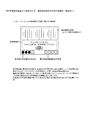
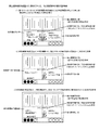
図11を用いて、本実施例における演出ボタンA、B(67、68)の操作が有効となる疑似図柄のリーチ演出の種類と、特定演出A、Bの種類と、有効期間Aから有効期間Bに変更するための操作条件との関係を説明する。(1)は、演出ボタンA、B(67、68)の操作が有効となるリーチ演出の種類と特定演出A、Bの種類との関係と、演出ボタンB68の有効時間との関係を示している。リーチ演出の種類は1から5の5種類となり、数字が大きなリーチ演出ほど大当り期待度が高い演出となる。また、特定演出Bは特定演出Aよりも実施中の図柄変動の当否判定結果を明確に予告する演出となっている(表示内容は図を用いて後述)。 Using FIG. 11, the types of pseudo-design reach effects, the types of specific effects A and B, and the effective period A to effective period in which the operations of the effect buttons A and B (67, 68) in this embodiment are effective. The relationship with the operation condition for changing to B will be described. (1) shows the relationship between the types of reach effects and the types of specific effects A and B for which the operations of the effect buttons A and B (67, 68) are valid, and the effective time of the effect buttons B68. Yes. There are five types of reach production, from 1 to 5, and the larger the number of reach production, the higher the expectation of jackpot. Further, the specific effect B is an effect for clearly notifying the result of determination of whether or not the symbol variation is being performed more than the specific effect A (display contents will be described later with reference to the drawings).
S337でセットされる有効期間は、リーチ演出の種類に対応してその時間が異なり、リーチ演出の種類の数字が大きくなるほど、即ち、期待度の大きな演出ほど有効期間は短くなっている。特定演出Aと特定演出Bとは、各リーチ演出に対してそれぞれ3種類の中から選択される。また、各リーチ演出の3種類の特定演出Bは、予告演出としての内容の明確さが段階的に異なる構成(例えば、B11<B12<b13の順に大当りの期待度がわかり易い)となっている。 The effective period set in S337 differs depending on the type of reach effect, and the effective period becomes shorter as the number of reach effect types increases, that is, the effect with higher expectation. The specific effects A and the specific effects B are selected from three types for each reach effect. In addition, the three types of specific effects B of each reach effect have a configuration in which the clarity of the content as the notice effect is different in stages (for example, the expected degree of jackpot is easy to understand in the order of B11 <B12 <b13).
図11(2)は、特定演出Bの種類に対応した判定期間と操作条件の関係を示し、本発明の変更条件決定手段に相当する。上述したように、期待度の高いリーチ演出で大当り期待度又は判定結果がよりわかり易い(より明確)な特定演出Bが選択された場合は、有効期間Aから有効期間Bに変化させるための条件は厳しくなる。例えば、最も期待度の高いリーチ演出5が選択された場合に、さらに最も明確な特定演出BであるB53が選択されると、操作を判定する判定期間は最も短い2.5秒が設定され、操作回数には最も多い7回が設定される。一方、期待度が最も低いリーチ演出1が選択された場合に明確度が最も低いB11が選択されると、操作を判定する判定期間は最も長い5.0秒が設定され、操作回数には最も少ない3回が設定される。
FIG. 11 (2) shows the relationship between the determination period corresponding to the type of the specific effect B and the operation condition, and corresponds to the change condition determination means of the present invention. As described above, when a specific effect B with a higher expectation degree and a big hit expectation degree or a determination result that is easier to understand (more clear) is selected, the condition for changing from the effective period A to the effective period B is It becomes severe. For example, when the
設定内容はこれに限るわけではなく、一つのリーチ演出の種類に対して、有効期間を複数種類の中から選択する構成としてもよいし、リーチ演出の種類によって設定可能な特定演出A、Bの数は異なる構成(例えば、リーチ演出1は2種類の中から一つが選択され、リーチ演出5は5種類の中から一つが選択されるなど)としてもよい。
The setting content is not limited to this, and the configuration may be such that the effective period is selected from a plurality of types for one type of reach production, or the specific productions A and B that can be set according to the type of reach production. The number may be different (for example, one of the
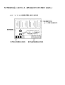
図12は、判定期間中の操作条件(演出ボタンA67の操作回数)達成状況に応じた有効期間の変化を示すタイミングチャート例となる。(1)のタイミングチャートは、判定期間を開始してから終了するまでに、演出ボタンA67の操作条件が達成されず、演出ボタンB68の操作も行われなかった場合(特定演出Aが表示されない)を示している。この場合、判定期間と有効期間を同時に開始すると、判定期間はS340でセットした判定時間が経過すると判定期間を終了し、有効期間はS337でセットした時間が経過すると、有効期間Bに変化することなく有効期間Aのまま有効期間を終了する。 FIG. 12 is an example of a timing chart showing the change of the effective period according to the achievement condition of the operation condition (the number of operations of the effect button A67) during the determination period. In the timing chart of (1), when the operation condition of the effect button A67 is not achieved and the operation of the effect button B68 is not performed from the start to the end of the determination period (the specific effect A is not displayed). Is shown. In this case, if the determination period and the effective period are started simultaneously, the determination period ends when the determination time set in S340 elapses, and the effective period changes to the effective period B when the time set in S337 elapses. The effective period ends without changing the effective period A.
(2)のタイミングチャートは、判定期間を開始してから終了するまでの間に、演出ボタンB68を操作(特定演出Aを表示)した場合を示している。この場合、演出ボタンB68が操作された時点で有効期間Aである有効期間と判定期間とを終了し、有効期間A中の演出ボタンB68の操作に応じて特定演出Aを演出図柄表示装置6に表示する。
The timing chart (2) shows a case where the effect button B68 is operated (the specific effect A is displayed) between the start and end of the determination period. In this case, the effective period that is the effective period A and the determination period are ended when the effect button B68 is operated, and the specific effect A is displayed on the effect
(3)のタイミングチャートは、判定期間を開始してから終了するまでの間に、演出ボタンA67の条件操作(特定演出Aを表示)が達成され、該達成時に有効期間が有効期間Aから有効期間Bに変化し有効期間Bの状態で演出ボタンB68が操作されないまま有効期間の終了時間に達した場合を示している。この場合、有効期間が有効期間Aから有効期間Bに変化していても、S337でセットした有効時間が経過すると、有効時間Bを終了している((1)で有効期間Aを終了するのと同じタイミングで終了)。 In the timing chart of (3), the conditional operation (displaying the specific effect A) of the effect button A67 is achieved between the start and end of the determination period, and the effective period is effective from the effective period A when the achievement is achieved. A case is shown in which the period changes to the period B and the end time of the effective period is reached without operating the effect button B68 in the state of the effective period B. In this case, even if the effective period has changed from the effective period A to the effective period B, the effective period B ends when the effective period set in S337 has elapsed (the effective period A ends in (1)). End at the same time).
(4)のタイミングチャートは、判定期間を開始してから終了するまでの間に、演出ボタンA67の条件操作(特定演出Aを表示)が達成され、有効期間が有効期間Aから有効期間Bに変化し、有効期間Bの状態で演出ボタンB68が操作された場合を示している。この場合、有効期間の有効期間Aから有効期間Bへの変化と同時に判定期間は終了し、演出ボタンB68の操作検出時に有効期間を終了するとともに、特定演出Bを演出図柄表示装置6に表示する。
In the timing chart of (4), the conditional operation (displaying the specific effect A) of the effect button A67 is achieved between the start and end of the determination period, and the effective period is changed from the effective period A to the effective period B. This shows a case where the effect button B68 is operated in the state of the effective period B. In this case, the determination period ends simultaneously with the change of the effective period from the effective period A to the effective period B, and the effective period ends when the operation of the effect button B68 is detected, and the specific effect B is displayed on the effect
次に図13を用いて、実施例1における演出図柄表示装置6に表示される、条件報知期間中の表示態様例を説明する。図13は、図12のタイミングチャートに示した条件報知期間の表示内容となる。具体的な表示内容は、画面のほぼ上半分は、左中右の疑似図柄表示部となりその下部が条件報知部となる。
Next, a display mode example during the condition notification period displayed on the effect
条件報知部に表示される内容は、チャンスタイム(判定期間を含む演出ボタンB68の有効期間)中に行う演出ボタンB68操作時に特定演出Bを表示させるために必要な操作条件となる。具体的には、条件報知部に「チャンスタイムになったらAボタンを3回押せば予告内容レベルアップ」の文字列を表示し、その文字列の下に、操作する演出ボタンA67(及びチャンスタイム中に操作が有効となる演出ボタンB68)を示す模式図を表示する。 The content displayed in the condition notification section is an operation condition necessary for displaying the specific effect B when the effect button B68 is operated during the chance time (the effective period of the effect button B68 including the determination period). More specifically, a character string “Press the A button three times when the chance time is reached to raise the level of notice content” is displayed in the condition notification section, and the effect button A67 to be operated (and the chance time) under the character string. A schematic diagram showing an effect button B68) in which the operation is effective is displayed.
図例では「3回押せば」となっているが、この回数は図11(2)の図表に示したように、リーチの種類及び、その時に選択されている特定演出Bの種類に応じて変化する。実施中の変動が期待度の高い演出を行い、さらに選択されている特定演出Bの内容が明確度の高い予告演出の場合ほど操作回数は多くなる(難易度が上がる)。従って、この条件報知部に、難易度が高い操作条件が表示されると、おのずと期待度の高いリーチ演出が出現することを予告したことになる。 In the example of the figure, it is “pressed 3 times”, but this number of times depends on the type of reach and the type of specific effect B selected at that time, as shown in the chart of FIG. Change. The number of operations increases (difficulty increases) as the variation during execution produces an effect with high expectation and the content of the selected specific effect B is a notice effect with high clarity. Therefore, when an operation condition with a high degree of difficulty is displayed in the condition notification unit, it is predicted that a reach effect with a high degree of expectation will appear.
次に、図14を用いて、演出図柄表示装置6に表示される有効期間中の表示態様例を説明する。(1)は、図12(1)(2)(3)(4)の有効期間(A)及び判定期間に表示する表示内容例となる。具体的な表示内容は、図13を用いて説明した条件報知部が、演出ボタンA67の操作に対応した条件操作指示部と、有効期間A中の演出ボタンB68の操作に対応した予告A操作指示部に分割され、表示例の条件操作指示部には、「Aボタンあと2回で予告レベルアップ」「現在1回」の文字列と、演出ボタンA67を示す模式図とその操作を促す矢印とを表示する。なお、「現在1回」の表示は、既に演出ボタンA67が1回操作されたことを示す。また、判定期間の残り時間を示す図形(メーター)又は数値を表示する構成としてもよい。
Next, the example of the display mode during the effective period displayed on the effect
予告A操作指示部には、「Bボタン今操作するとレベル1の予告」と、演出ボタンB68を示す模式図とその操作を促す矢印とを表示する。また、条件操作指示部と予告A操作指示部とにまたがって「チャンスタイム」の文字列が表示される。
In the notice A operation instruction section, “B button now operated,
(2)は、判定期間中に演出ボタンA67の操作条件が達成された場合に表示される内容を示している。この場合、(1)の条件操作指示部が条件操作完了報知部に変化し、予告A操作指示部が予告B操作指示部に変化する。条件操作完了報知部の具体的な表示内容は、「予告レベルUP」「操作完了」の文字列が表示され、操作の必要がなくなった演出ボタンA67の操作を促す模式図は表示しない。予告B操作指示部の具体的な表示内容は、「BボタンレベルUP予告」の文字列と、引き続き演出ボタンB68を示す模式図とその操作を促す矢印とを表示する。それぞれに表示した文字列が(1)から(2)のように変化したことにより、演出ボタンB68を操作した場合に表示される予告内容がより遊技者が知りたい情報(明確)に変化したことが認識可能となる。 (2) shows the contents displayed when the operating condition of the effect button A67 is achieved during the determination period. In this case, the conditional operation instruction unit (1) is changed to the conditional operation completion notification unit, and the advance notice A operation instruction unit is changed to the advance notice B operation instruction unit. The specific display contents of the conditional operation completion notifying unit are displayed as character strings “notice level UP” and “operation completed”, and do not display a schematic diagram that prompts the user to operate the effect button A67 that is no longer necessary. The specific display contents of the advance notice B operation instructing unit display a character string “B button level up advance notice”, a schematic diagram showing the effect button B68, and an arrow for prompting the operation. Due to the change in the character strings displayed on each of the buttons from (1) to (2), the notice content displayed when the production button B68 is operated has changed to information (clear) that the player wants to know. Can be recognized.
(3)は、判定期間中に演出ボタンA67の操作条件が達成されなかった場合に表示される内容を示している。この場合、(1)の条件操作指示部が操作期間終了報知部に変化し、(1)の予告A操作指示部の表示内容が変化し、操作期間終了報知部には「Aボタン操作期間終了」「操作未完了」の文字列を表示し、操作の判定期間が終了した演出ボタンA67の操作を促す模式図と矢印の表示は消す。また、予告A操作指示部の表示内容は文字列が「Bボタンレベル1予告」に変化し、演出ボタンB68の操作を促す模式図と矢印の表示は継続する。本実施例では、上記した内容で判定期間及び有効期間の報知を行うがもちろんこれに限るわけではなく、演出ボタンA67が有効かどうか、演出ボタンBの操作に応じてどの予告が出現するのかがが認識可能に報知されればよい。
(3) shows the contents displayed when the operating condition of the effect button A67 is not achieved during the determination period. In this case, the condition operation instruction unit (1) changes to an operation period end notification unit, the display content of the notice A operation instruction unit (1) changes, and the operation period end notification unit displays “A button operation period end”. The character string “unfinished operation” is displayed, and the schematic diagram and the arrow display prompting the user to operate the effect button A67 whose operation determination period has ended are turned off. In addition, the display content of the notice A operation instruction section changes the character string to “
次に、図15、16を用いて演出図柄表示装置6に表示する特定演出Aと特定演出Bの表示例を説明する。図15(1)は、図14(1)又は(3)の状態である有効期間Aにおいて、演出ボタンB68が操作された場合に表示される特定演出Aの表示例1となる。この特定演出Aは、遊技者にとってはレベル1の予告演出であり漠然とした当否判定結果を報知する予告演出(明確度が低い予告演出)となる。具体的な表示例1の表示内容は、条件操作指示部と予告A操作指示部とが特定演出表示部となり、その特定演出表示部内の左位置にキャラクタ(熊の達吉)が表示され、その右側に達吉のコメントとして「あたるかな」の文字列が表示される。表示例1の特定演出Aはコメント系の予告演出であり、他に「あついよ」「もうちょっと」「がんばれ」等があるが、どれも当否判定結果に対する予告としては曖昧であり、遊技者は漠然としたイメージしか受け取れない内容となっている。
Next, display examples of the specific effects A and the specific effects B displayed on the effect
図15(2)も、図14(1)又は(3)の状態である有効期間Aにおいて、演出ボタンB68が操作された場合に表示される特定演出Aの表示例2となる。(1)がコメントの内容が予告であったのに対して、(2)はキャラクタ及びキャラクタ周りの色の変化によって予告するものとなっている。具体的には、出現した達吉又は達吉の周辺が青色なら期待度小、黄色なら期待度中、赤色なら期待度大を予告する。この場合も期待度が大中小の3種類で報知されるに留まり、遊技者に対しては漠然とした期待感しか与えられない。 FIG. 15 (2) is also a display example 2 of the specific effect A that is displayed when the effect button B68 is operated in the effective period A that is the state of FIG. 14 (1) or (3). In (1), the content of the comment is a notice, whereas in (2), the notice is given by the character and the color change around the character. Specifically, when the appearance of Tatsuyoshi or around Tatsuyoshi is blue, the degree of expectation is low, when yellow, the degree of expectation is predicted, and when red, the degree of expectation is predicted. In this case as well, the degree of expectation is limited to three types of large, medium and small, and only a vague expectation is given to the player.
図16(1)は、図14(2)の状態である有効期間Bにおいて、演出ボタンB68が操作された場合に表示される特定演出Bの表示例1となる。この特定演出Bは、遊技者にとっては有効期間Aの時に表示されるレベル1の予告演出(漠然とした予告演出)からレベルアップした予告演出(特定演出Aよりも明確に当否判定結果または期待度を計ることができる)となる。特定演出Bの表示例1の具体的な表示は、上述した特定演出表示部の左位置に「熊の達吉」が表示され、その右側に達吉のコメントとして「大当り」の文字列が表示される。特定演出Bのコメント系の予告としては、他に「ハズレ」「当たれば確変」「○図柄で大当り」等があり、特定演出Aの予告演出に対して、どの予告も実施中の変動表示結果を明確に示唆する内容となっている。 FIG. 16 (1) is a display example 1 of the specific effect B displayed when the effect button B68 is operated in the effective period B which is the state of FIG. 14 (2). For the player, the specific effect B is a level-up notice effect (vague notice effect) displayed during the effective period A for the player. Can be measured). The specific display in the display example 1 of the specific effect B is that “Tatsuyoshi Kumano” is displayed at the left position of the above-mentioned specific effect display unit, and the character string “big hit” is displayed as the comment of Tatsuyoshi on the right side. . Other commentary notices for specific production B include “losing”, “probable change when hit”, “○ jackpot with symbol”, etc. It is a content that clearly suggests.
図16(2)は、有効期間B(図14(2)の状態)において、演出ボタンB68が操作された場合に表示される特定演出Bの表示例2となる。(1)がコメントの内容によって当否結果や期待度を示唆するのに対して、(2)は数値%を表示して当否結果を示唆する内容となっている。具体的な表示例2の表示内容は、キャラクタ(熊の達吉)の右に「大当り期待度80%」を表示する。数値表示系の予告としては表示される数値が100%、90%、70%、60%、50%であったり、「確変期待度○○%」(○○には数値が入る)といった内容を表示する。 FIG. 16 (2) is a display example 2 of the specific effect B displayed when the effect button B68 is operated in the effective period B (state of FIG. 14 (2)). While (1) suggests the result or expectation level depending on the content of the comment, (2) displays the numerical value% to indicate the result. Specifically, the display content of display example 2 displays “expected degree of big hit 80%” to the right of the character (Tatsuyoshi Kumano). As a notice of numerical display system, the displayed numerical value is 100%, 90%, 70%, 60%, 50%, or the content such as “Expected probability of change ○○%” (○○ is a numerical value) indicate.
また、特定演出Bは特定演出Aと比べ、予告の種類が多い構成となっている。どちらの特定演出も同じ種類の表示演出を実施する場合は、表示する種類が多いほうが、より明確な抽選結果を示唆することが可能な構成といえる。 In addition, the specific effect B has a greater number of types of notices than the specific effect A. In the case where both of the specific effects are performed with the same type of display effect, it can be said that the more types of display effect are, the more clearly the lottery result can be suggested.
また、特定演出Aが大当り期待度を小、中、大の3種類の文字を用いるのに対して、特定演出Bが10%、30%、50%、80%、100%と、%表示を用いて大当り期待度を予告した場合、表示態様の精度及びその表示数の多様性から明らかに特定演出Bがより明確な抽選結果を示唆する演出といえる。 In addition, while the specific effect A uses three types of characters, small, medium and large, the expected degree of big hit, the specific effect B displays 10%, 30%, 50%, 80%, 100% and% display. When the jackpot expectation degree is predicted in advance, it can be said that the specific effect B clearly suggests a clearer lottery result from the accuracy of the display mode and the diversity of the display number.
次に実施例2について説明する。実施例1では、判定期間内における演出ボタンA67の操作回数を、有効期間Aから有効期間Bに変化させるための条件としたが、本実施例では、判定期間内における遊技領域3に配置されたゲートへの遊技球の通過数を有効期間Aから有効期間Bに変化させるための条件としている。従って、実施例1と異なるのは、上記したゲートに係る構成(ゲートの配置と電気的な接続構成)と、図13を用いて説明した、演出図柄表示装置6に表示される、条件報知期間中の表示態様となるため、異なる点のみ説明し、特に説明のない部分については実施例1を援用する。
Next, Example 2 will be described. In the first embodiment, the number of operations of the effect button A67 within the determination period is set as a condition for changing from the effective period A to the effective period B. However, in the present embodiment, the operation button A67 is arranged in the
図17に示す図は、実施例2における遊技盤1の正面図となる。図2に示した実施例1の正面図と異なるのは、ゲート17の下に条件ゲート15が配置された点のみとなり、そのほかは実施例1と共通となる。この遊技盤面の構成により、発射により遊技領域3に到達し、センターケース5の左側を流下する遊技球は、条件ゲート15を通過する可能性のある遊技球となる。
The diagram shown in FIG. 17 is a front view of the
図18は実施例2におけるパチンコ機50の電気的構成を示すブロック図となり、主制御装置80への入力端に条件ゲート15を通過する遊技球を検出する条件スイッチ15aが追加されている。本実施例では条件スイッチ15aを主制御装置80に接続したが、サブ統合制御装置83に直接接続してもよいし、払出制御装置81に接続してもよく、直接か間接かを問わず、条件スイッチ15aが遊技球を検出したことを示す信号がサブ統合制御装置83に入力される構成であればよい。また、本実施例では条件判定用にそれ専用の条件ゲート15を備える構成としたが、他のスイッチ(例えば、第1始動口スイッチ11a、第2始動口スイッチ12a、普通図柄作動スイッチ17a、左入賞スイッチ31a)を条件判定に兼用する構成としてもよい。
FIG. 18 is a block diagram showing the electrical configuration of the
図19は、実施例2における、演出図柄表示装置6に表示される条件報知期間中の表示態様例となる。この図19も図12と同様に、図11のタイミングチャートに示した条件報知の表示内容となる。本実施例においても条件報知部に表示される内容は、チャンスタイム(判定期間)中に行う演出ボタンB68操作時に特定演出Bを表示させるために必要な操作条件となり、具体的には、条件報知部の右側に「チャンスタイムになったらチャンスゲートに3個通せば予告内容レベルアップ」の文字列を表示し、左側に、ゲート17と条件ゲート15との模式図と条件ゲートを指し示す矢印を表示する。
FIG. 19 shows a display mode example during the condition notification period displayed on the effect
図例では「3個通せば」となっているが、この個数は実施例1と同様に選択された特定演出Bの種類に応じて設定された個数となる。また、条件操作(この場合は条件ゲート15の通過数)の設定とその制御は、実施例1の演出ボタンA67の操作回数が通過数となるだけで、設定内容と制御内容に変わりはない。また、演出図柄表示装置6に表示される判定期間を示す表示態様も、演出ボタンA67の操作回数を条件ゲート15の通過数に置き換えたものとなる。
In the example shown in the figure, “Three passes” is the number set according to the type of the specific effect B selected as in the first embodiment. The setting and control of the conditional operation (in this case, the number of passages of the condition gate 15) is merely the number of operations of the effect button A67 of the first embodiment, and the setting content and the control content are not changed. In addition, the display mode indicating the determination period displayed on the effect
以上が実施例2の説明となる。この構成では遊技球を条件ゲート15を狙って発射することになるが、演出ボタンA67の操作とは異なり、狙って発射した遊技球が全て条件ゲート15を通過するとは限らないため、運任せに頼る部分も多くなる。従って、判定期間の時間を実施例1で用いたものよりも長くする構成が好適である。条件設定として条件ゲート15への入球数を多くすれば条件を達成するための難易度は上昇し、同様に判定期間を短くしても難易度は上昇する。
The above is the description of the second embodiment. In this configuration, the game ball is fired aiming at the
本実施例では、条件ゲート15の通過数を条件操作として検出したが、単に発射遊技球数を条件操作としてもよく、その場合は発射球を検出するスイッチを遊技領域3の入り口に配置し、遊技領域3に到達した遊技球を計数してもよいし、発射された直後の遊技球を計数可能にスイッチを配置してもよい。但し、発射された直後の遊技球を計数する場合は、ファール球が発生する可能性があり発射した全ての遊技球が遊技領域3に到達するわけではないため、ファール球が発生する可能性がある分、遊技領域3に到達した遊技球のみ計測する場合は条件を低くする等条件設定を考慮する必要がある。
In the present embodiment, the number of passes through the
また、所定数の遊技球を機内に封入し、発射した遊技球を遊技機内で回収して循環的に使用することで遊技を行う封入式遊技機とした場合、封入式遊技機が元々備える発射球数の計数機能を用いて条件操作を判定する構成とすればよい。 In addition, when a predetermined number of game balls are enclosed in the aircraft, and the fired game balls are collected in the game machine and used in a circulating manner, the enclosed game machine is originally provided with the enclosed game machine. A condition operation may be determined using a ball count function.
本実施例のように、発射した遊技球により条件を達成する構成とした場合、発射を停止してしまうことが多々あるリーチ演出に係る変動表示中に判定期間を実施することにより、当該変動中における遊技球の発射停止を抑止することが可能となる。 As in the present embodiment, when the condition is achieved by the game ball that has been launched, the launch is often stopped by performing the determination period during the variation display related to the reach effect that often stops the launch. It is possible to prevent the game ball from being stopped from firing.
実施例2においても、演出ボタンB68の操作が可能となる有効期間が発生する演出変動(リーチ演出)の条件報知、判定期間、有効期間A、Bの出現タイミングは、図12を用いて説明した内容と変わりないが、図20、21に示した構成としてもよい。 Also in the second embodiment, the condition notification of the effect variation (reach effect) in which the effective period in which the effect button B68 can be operated (reach effect), the determination period, and the appearance timing of the effective periods A and B are described with reference to FIG. Although not different from the contents, the configuration shown in FIGS.
図20(1)(2)は、判定期間中に操作条件が達成されると判定期間が終了するのを待って有効期間が変化する(有効期間A→有効期間B)場合のタイミングチャートとなる(図12を用いて説明したタイミングチャートは、操作条件が達成されると、達成された時点で判定期間が終了するとともに有効期間Aが有効期間Bに変化する構成)。この場合においても、図20(1)に示すように、判定期間中に操作条件が達成されなかった場合は、有効期間(有効期間A)が有効期間終了時まで継続する。(2)のタイミングチャートに示すように、判定期間が終了する以前に操作条件が達成された場合、S340で設定した判定時間が終了したことを契機として有効期間が有効期間Aから有効期間Bに変化し有効期間終了時に至る。この構成では、判定期間中のどの時点で操作条件が達成されても有効期間Aと有効期間Bの長さは不変となる。 FIGS. 20 (1) and 20 (2) are timing charts when the effective period changes after the determination period ends when the operation condition is achieved during the determination period (effective period A → effective period B). (The timing chart described with reference to FIG. 12 is a configuration in which when the operation condition is achieved, the determination period ends and the effective period A changes to the effective period B when the operation condition is achieved). Also in this case, as shown in FIG. 20 (1), when the operation condition is not achieved during the determination period, the effective period (effective period A) continues until the end of the effective period. As shown in the timing chart of (2), when the operation condition is achieved before the end of the determination period, the effective period is changed from the effective period A to the effective period B when the determination time set in S340 ends. It changes and reaches the end of the effective period. In this configuration, the lengths of the effective period A and the effective period B are unchanged regardless of when the operation condition is achieved at any point in the determination period.
図20(3)(4)は、判定期間と有効期間が重ならない構成とした場合のタイミングチャート例である。(3)は、条件報知期間後の判定期間中に操作条件が達成されなかった場合のタイミングチャートとなり、この場合は判定期間が終了してから有効期間となるがその有効期間は有効期間Aとなる。(4)は、条件報知期間後の判定期間中に操作条件が達成された場合のタイミングチャートとなる。この場合も操作条件の達成時期に拘らず設定された判定時間が経過してから有効期間となるが、操作条件が達成されているため発生する有効期間は有効期間Bとなる。 FIGS. 20 (3) and 20 (4) are timing chart examples in the case where the determination period and the effective period do not overlap. (3) is a timing chart when the operation condition is not achieved during the determination period after the condition notification period. In this case, the effective period is the effective period A after the determination period ends. Become. (4) is a timing chart when the operation condition is achieved during the determination period after the condition notification period. In this case as well, the valid period is reached after the set determination time has elapsed regardless of the achievement timing of the operation condition. However, the valid period that is generated because the operation condition is achieved is the valid period B.
また、操作条件の達成によって有効期間が有効期間Aから有効期間Bに変化するだけでなく、発生する有効期間の長さも変化する構成としてもよい。例では有効期間が延長されているが、有効期間を短くしてもよいし、有効期間Aと同一の長さでもよい。 In addition, the effective period may be changed from the effective period A to the effective period B by the achievement of the operation condition, and the length of the generated effective period may be changed. In the example, the effective period is extended, but the effective period may be shortened or may be the same length as the effective period A.
図12、20を用いて説明したタイミングチャート例のように、操作条件を達成した場合には、判定期間中にすでに実施している有効期間を有効期間Aから有効期間Bに変化させるだけでなく、判定期間後に発生する予定の有効期間を操作条件の達成状況に応じて変化させる構成としてもよい(図20(3)(4))。 As in the timing chart examples described with reference to FIGS. 12 and 20, when the operation condition is achieved, not only the effective period already performed during the determination period is changed from the effective period A to the effective period B. The effective period scheduled to occur after the determination period may be changed in accordance with the achievement status of the operation condition (FIGS. 20 (3) and (4)).
次に、図21を用いて、先読判定結果に基づいて、特別図柄の複数回の変動表示に亘って、上記した「条件報知」「判定期間」「有効期間」のそれぞれを1回の変動表示期間中に実施する場合のタイミングチャート例を説明する。例は、3回の連続した特別図柄の変動表示に亘って、「条件報知」、「判定期間」、「有効期間A又は有効期間B」を各変動表示中に実施した場合となる。 Next, based on the pre-reading determination result, each of the above-mentioned “condition notification”, “determination period”, and “valid period” is changed once over the variation display of the special symbol using FIG. 21. An example of a timing chart in the case of performing during the display period will be described. An example is a case where “condition notification”, “determination period”, and “effective period A or effective period B” are performed during each variable display over three consecutive special symbol variable displays.
(1)は、2回目の特別図柄の変動表示中に実施される判定期間中に操作条件が達成されなかった場合となり、この場合は、3回目の変動表示中に有効期間Aが発生し、有効期間A中に演出ボタンB68を操作すると当該3回目の変動の当否判定結果又は期待度を報知する特定演出Aを実施する。(2)は、2回目の変動表示で実施される判定期間中に操作条件が達成された場合となり、この場合は、3回目の変動表示は有効期間Bとなる。3回目の変動表示中に有効期間Bが発生し、有効期間B中に演出ボタンB68を操作すると当該3回目の変動の当否判定結果又は期待度を報知する予告演出として特定演出Aよりも明確度の高い特定演出Bを実施する。 (1) is when the operating condition is not achieved during the determination period that is performed during the second variation display of the special symbol. In this case, the effective period A occurs during the third variation display, When the effect button B68 is operated during the effective period A, the specific effect A for informing the determination result or expectation degree of the third fluctuation is performed. (2) is when the operation condition is achieved during the determination period implemented in the second variation display. In this case, the third variation display is the effective period B. When the effective period B occurs during the third variation display, and the effect button B68 is operated during the effective period B, the clarity effect is higher than the specific effect A as a notice effect that informs the result of the determination of the success or expectation of the third variation. A high specific performance B is performed.
図21に示したタイミングチャートは、サブ統合制御装置83が、受信した先読判定コマンドを記憶する構成とし、受信した先読判定コマンドの内容が大当りの期待できる演出が可能であった場合(リーチor大当り)、既に記憶している先読判定コマンドの内容に大当りを期待させる演出が可能なものがないこと条件に、前記大当りが期待できる演出を開始するまでに、該大当りが期待できる演出で実施する予告演出をレベルアップ(明確度を高く)するための「条件報知」と、条件報知された内容の操作が行われたか否かの「条件判定(判定期間)」とを保留記憶による変動演出中に行い、前記大当りが期待できる演出を開始すると条件が達成されていなければ有効期間Aを実施し、達成されていれば有効期間Bを実施する構成となる。
The timing chart shown in FIG. 21 is configured so that the
例には、連続した3回の変動表示で実施する構成を示したが、連続した2回の変動で実施する場合は、「条件報知」と「判定期間」とを1回の変動表示中に実施してもよいし、「判定期間」と「有効期間」とを1回の変動表示中に実施してもよい。また、4回の変動で実施する場合は、「条件報知」を1回目と2回の変動表示で行ってもよい。 The example shows a configuration that is implemented with three consecutive fluctuation displays, but when implemented with two consecutive fluctuations, "condition notification" and "judgment period" are displayed during one fluctuation display. Alternatively, the “determination period” and the “valid period” may be performed during one fluctuation display. Moreover, when implementing by the fluctuation | variation of 4 times, you may perform "condition alerting | reporting" by the fluctuation | variation display of the 1st time and 2 times.
以上が実施例の説明となる。操作条件の難易度は、実施するリーチ演出の大当り期待度と選択された特定演出Bの組合せに応じて選択される構成として説明したが、実施するリーチ演出が大当り期待度の高いものであっても、実際の当否判定結果がハズレであれば特定演出Bに明確度の高い演出が選ばれていても操作条件の難易度を低く設定する構成も考えられる。この構成により、期待度の高いリーチ演出であっても、操作条件の難易度が低ければ、この難易度の低さが遊技者に当否判定結果を示唆する構成となる。 The above is the description of the embodiment. The difficulty of the operating conditions has been described as a configuration selected according to the combination of the jackpot expectation level of the reach effect to be performed and the selected specific effect B, but the reach effect to be performed has a high jackpot expectation level. In addition, if the actual determination result is lost, even if an effect with a high degree of clarity is selected as the specific effect B, a configuration in which the difficulty level of the operation condition is set low can be considered. According to this configuration, even if the reach effect has a high expectation level, if the difficulty level of the operation condition is low, the low difficulty level indicates a result of determining whether or not the player is successful.
また、実施例1においては、有効期間A又は有効期間B中に演出ボタンB68が1回操作されれば、有効期間の種類に応じた特定演出A又はBが実施され有効期間は終了するが、演出ボタンB68の操作が予め設定された回数だけ操作されると特定演出を実施して有効期間を終了する構成としてもよく、この場合も、操作しなければならない回数が多いほど、遊技者が知りたい情報の明確度が上がる構成が望ましい。この構成の有効期間Aでは、演出ボタンA67と演出ボタンB68との両方ともに複数回の操作が必要となるが、操作回数を比較してどちらの演出ボタンを操作するか遊技者が選択するという遊技性を提供することができる。 Moreover, in Example 1, if the production button B68 is operated once during the effective period A or the effective period B, the specific effect A or B corresponding to the type of the effective period is performed and the effective period ends. When the operation of the effect button B68 is operated for a preset number of times, a specific effect may be implemented and the effective period may be terminated. In this case, the player knows that the more times the operation has to be performed, It is desirable to increase the clarity of the information you want. In the effective period A of this configuration, both the effect button A67 and the effect button B68 require a plurality of operations, but the player selects which effect button to operate by comparing the number of operations. Can provide sex.
具体的には、有効期間Aから有効期間Bに変化させるための条件が低い(演出ボタンA67の操作回数条件が少ない)場合、変化した有効期間Bで実施する特定演出Bの内容は明確度の低い内容であることが予想できるが、演出ボタンA67の条件操作と同時に報知された有効期間Aにおける特定演出Aの出現条件(演出ボタンB68の操作回数)が演出ボタンA67の操作回数よりも多ければ、有効期間が変化した場合に実施される特定演出Bよりも明確度の高い特定演出Aが実施される場合がある構成としてもよい。これは、サブ統合制御装置83が備える全ての特定演出Aが全ての特定演出Bよりもその明確度が低いわけではなく、特定演出Aであっても特定演出Bよりも明確度が高い予告演出を備える構成とすればよい。
Specifically, when the condition for changing from the effective period A to the effective period B is low (the operation button A67 has a small number of operation conditions), the content of the specific effect B performed in the changed effective period B is of clarity. Although the content can be expected to be low, if the appearance condition of the specific effect A (the number of operations of the effect button B68) in the effective period A notified at the same time as the condition operation of the effect button A67 is greater than the number of operations of the effect button A67. The specific effect A having a higher degree of clarity than the specific effect B performed when the effective period changes may be implemented. This is because not all the specific effects A included in the sub integrated
以上のように、本発明の弾球遊技機によれば、遊技者の操作に応じて異なる予告演出を出現させる有効期間を複数備え、該有効期間を遊技者の操作によって変化させる構成としたため遊技者の意思が大きく反映することが可能な構成となっている。従って、操作手段を備えた弾球遊技機に適用することができる。 As described above, according to the ball game machine of the present invention, a plurality of effective periods for causing different notice effects to appear according to the player's operation are provided, and the effective period is changed by the player's operation. It is a structure that can reflect the will of the person greatly. Therefore, the present invention can be applied to a ball game machine equipped with an operation means.
1 遊技盤
6 演出図柄表示装置
11 第1始動口
11a 第1始動口スイッチ
12 第2始動口
12a 第2始動口スイッチ
17 ゲート
17a 普通図柄作動スイッチ
67 演出ボタンA
68 演出ボタンB
67a 演出ボタンAスイッチ
68a 演出ボタンBスイッチ
80 主制御装置
82 演出図柄制御装置
83 サブ統合制御装置
DESCRIPTION OF
68 Production Button B
67a Production
Claims (1)
該主制御装置から送信される信号に基づいて制御を行うサブ制御装置と、
該サブ制御装置に設けられ、前記信号に基づいて演出図柄表示装置に表示する前記特別図柄の擬似演出を複数の擬似演出の中より選択する擬似演出選択手段と、
遊技者が操作可能な操作手段と、
を備え、
所定の前記擬似演出中に前記操作手段の操作が有効となる有効期間Aを発生させ、該有効期間A中に前記操作手段を操作すると、前記判定の結果を示唆する演出となる特定演出Aが行われる弾球遊技機において、
前記有効期間Aを有効期間Bに変更する有効期間変更手段と、
遊技者に向けて、該変更の条件を報知する変更条件報知手段と、
該変更条件報知手段によって報知される前記変更の条件には、達成するための難易度が異なる複数の条件があり、該複数の条件から前記変更条件報知手段によって報知する条件を決定する変更条件決定手段と、
前記変更条件報知手段によって報知された条件が所定期間中に達成できたか否かを判定する成否判定手段と、を備え、
前記有効期間変更手段は、前記大当り遊技を発生させるか否かの判定結果が、前記大当り遊技を発生させないという判定であっても前記有効期間Aを前記有効期間Bに変更可能であり、
前記成否判定手段が、前記変更条件報知手段によって報知された条件が達成されたと判断した場合には、前記有効期間変更手段によって前記有効期間Aを前記有効期間Bに変更するようにし、
前記有効期間変更手段によって前記有効期間Aから変更された前記有効期間Bは、前記有効期間Aに戻ることはなく、
前記有効期間B中に前記操作手段が操作されると、判定結果を示唆する演出であって前記特定演出Aとは異なる特定演出Bが行われるようにし、
前記有効期間A中に前記操作手段が操作されなかったら、予め定められた終了タイミングで前記有効期間Aを終了させるようにし、
前記所定期間を前記有効期間A内に設け、
前記有効期間変更手段は、前記終了タイミングになる前に前記有効期間Aを終了させて、前記有効期間Bを開始させるようにし、
前記有効期間B中に前記操作手段が操作されなかったら前記終了タイミングで前記有効期間Bを終了させる
ことを特徴とする弾球遊技機。 It is determined whether or not to generate a big hit game advantageous to the player based on the random number extracted due to the game ball entering the starting port, and the result of the determination is confirmed after the special symbol is displayed. A main control device which notifies by display;
A sub-control device that performs control based on a signal transmitted from the main control device;
A pseudo effect selecting means provided in the sub-control device, for selecting a pseudo effect of the special symbol displayed on the effect symbol display device based on the signal from a plurality of pseudo effects;
An operation means operable by the player
With
When an effective period A during which the operation of the operation means is effective is generated during the predetermined pseudo-effect, and the operation means is operated during the effective period A, the specific effect A serving as an effect suggesting the determination result is obtained. In the ball game machine to be performed,
An effective period changing means for changing the effective period A to an effective period B;
Change condition notifying means for notifying the player of the condition of the change;
The change condition notified by the change condition notification means includes a plurality of conditions having different degrees of difficulty to achieve, and a change condition determination for determining a condition notified by the change condition notification means from the plurality of conditions Means,
And a success determining means for determining whether the notification conditions have been achieved during a predetermined time period by the change condition notification means,
The effective period changing means can change the effective period A to the effective period B even if the determination result whether or not to generate the jackpot game is a determination that the jackpot game is not generated.
If the success / failure determination unit determines that the condition notified by the change condition notification unit has been achieved, the effective period change unit changes the effective period A to the effective period B;
The effective period B changed from the effective period A by the effective period changing means does not return to the effective period A,
When the operation means is operated during the effective period B, a specific effect B different from the specific effect A, which is an effect suggesting a determination result, is performed,
If the operating means is not operated during the effective period A, the effective period A is ended at a predetermined end timing,
Providing the predetermined period within the effective period A;
The effective period changing means ends the effective period A before the end timing, and starts the effective period B,
If the operating means is not operated during the effective period B, the effective period B is ended at the end timing.
Priority Applications (1)
| Application Number | Priority Date | Filing Date | Title |
|---|---|---|---|
| JP2014019293A JP6349511B2 (en) | 2013-02-07 | 2014-02-04 | Bullet ball machine |
Applications Claiming Priority (3)
| Application Number | Priority Date | Filing Date | Title |
|---|---|---|---|
| JP2013021897 | 2013-02-07 | ||
| JP2013021897 | 2013-02-07 | ||
| JP2014019293A JP6349511B2 (en) | 2013-02-07 | 2014-02-04 | Bullet ball machine |
Publications (3)
| Publication Number | Publication Date |
|---|---|
| JP2014168677A JP2014168677A (en) | 2014-09-18 |
| JP2014168677A5 JP2014168677A5 (en) | 2017-02-23 |
| JP6349511B2 true JP6349511B2 (en) | 2018-07-04 |
Family
ID=51691558
Family Applications (3)
| Application Number | Title | Priority Date | Filing Date |
|---|---|---|---|
| JP2014019293A Active JP6349511B2 (en) | 2013-02-07 | 2014-02-04 | Bullet ball machine |
| JP2014019292A Active JP5838390B2 (en) | 2013-02-07 | 2014-02-04 | Bullet ball machine |
| JP2014019294A Active JP6349512B2 (en) | 2013-02-07 | 2014-02-04 | Bullet ball machine |
Family Applications After (2)
| Application Number | Title | Priority Date | Filing Date |
|---|---|---|---|
| JP2014019292A Active JP5838390B2 (en) | 2013-02-07 | 2014-02-04 | Bullet ball machine |
| JP2014019294A Active JP6349512B2 (en) | 2013-02-07 | 2014-02-04 | Bullet ball machine |
Country Status (1)
| Country | Link |
|---|---|
| JP (3) | JP6349511B2 (en) |
Families Citing this family (2)
| Publication number | Priority date | Publication date | Assignee | Title |
|---|---|---|---|---|
| JP2017035310A (en) * | 2015-08-11 | 2017-02-16 | 株式会社大一商会 | Game machine |
| JP2018117929A (en) * | 2017-01-26 | 2018-08-02 | 株式会社サンセイアールアンドディ | Game machine |
Family Cites Families (9)
| Publication number | Priority date | Publication date | Assignee | Title |
|---|---|---|---|---|
| JP2005160867A (en) * | 2003-12-04 | 2005-06-23 | Sankyo Kk | Game machine |
| JP4414941B2 (en) * | 2005-06-28 | 2010-02-17 | 株式会社ニューギン | Game machine |
| JP5195262B2 (en) * | 2008-10-14 | 2013-05-08 | タイヨーエレック株式会社 | Game machine |
| JP5339994B2 (en) * | 2009-03-31 | 2013-11-13 | 株式会社平和 | Game machine |
| JP5077302B2 (en) * | 2009-07-02 | 2012-11-21 | タイヨーエレック株式会社 | Game machine |
| JP5231385B2 (en) * | 2009-12-11 | 2013-07-10 | 株式会社三共 | Game machine |
| JP5574744B2 (en) * | 2010-02-19 | 2014-08-20 | 株式会社三共 | Game machine |
| JP5476218B2 (en) * | 2010-06-10 | 2014-04-23 | 株式会社平和 | Pachinko machine |
| JP5465624B2 (en) * | 2010-07-01 | 2014-04-09 | 株式会社ニューギン | Game machine |
-
2014
- 2014-02-04 JP JP2014019293A patent/JP6349511B2/en active Active
- 2014-02-04 JP JP2014019292A patent/JP5838390B2/en active Active
- 2014-02-04 JP JP2014019294A patent/JP6349512B2/en active Active
Also Published As
| Publication number | Publication date |
|---|---|
| JP5838390B2 (en) | 2016-01-06 |
| JP2014168678A (en) | 2014-09-18 |
| JP6349512B2 (en) | 2018-07-04 |
| JP2014168677A (en) | 2014-09-18 |
| JP2014168676A (en) | 2014-09-18 |
Similar Documents
| Publication | Publication Date | Title |
|---|---|---|
| JP2013226404A (en) | Pinball game machine | |
| JP6592656B2 (en) | Bullet ball machine | |
| JP6554331B2 (en) | Game machine | |
| JP2014230611A (en) | Bouncing game machine | |
| JP6263710B2 (en) | Bullet ball machine | |
| JP6201116B2 (en) | Bullet ball machine | |
| JP2016036391A (en) | Pinball game machine | |
| JP6349511B2 (en) | Bullet ball machine | |
| JP2016063990A (en) | Pinball game machine | |
| JP2018192106A (en) | Pinball game machine | |
| JP7071734B2 (en) | Pachinko machine | |
| JP2016087258A (en) | Pinball game machine | |
| JP2019208733A (en) | Pinball game machine | |
| JP6592669B2 (en) | Game machine | |
| JP2015229036A (en) | Pinball game machine | |
| JP7116472B2 (en) | ball game machine | |
| JP6364588B2 (en) | Game machine | |
| JP6281051B2 (en) | Game machine | |
| JP6586588B2 (en) | Bullet ball machine | |
| JP2019195528A (en) | Pinball game machine | |
| JP2021137336A (en) | Pinball game machine | |
| JP2021137337A (en) | Pinball game machine | |
| JP2021137109A (en) | Pinball game machine | |
| JP6375495B2 (en) | Bullet ball machine | |
| JP2015228879A (en) | Pinball game machine |
Legal Events
| Date | Code | Title | Description |
|---|---|---|---|
| A521 | Written amendment |
Free format text: JAPANESE INTERMEDIATE CODE: A523 Effective date: 20170123 |
|
| A621 | Written request for application examination |
Free format text: JAPANESE INTERMEDIATE CODE: A621 Effective date: 20170125 |
|
| A977 | Report on retrieval |
Free format text: JAPANESE INTERMEDIATE CODE: A971007 Effective date: 20171013 |
|
| A131 | Notification of reasons for refusal |
Free format text: JAPANESE INTERMEDIATE CODE: A131 Effective date: 20171020 |
|
| A521 | Written amendment |
Free format text: JAPANESE INTERMEDIATE CODE: A523 Effective date: 20171208 |
|
| TRDD | Decision of grant or rejection written | ||
| A01 | Written decision to grant a patent or to grant a registration (utility model) |
Free format text: JAPANESE INTERMEDIATE CODE: A01 Effective date: 20180403 |
|
| A61 | First payment of annual fees (during grant procedure) |
Free format text: JAPANESE INTERMEDIATE CODE: A61 Effective date: 20180404 |
|
| R150 | Certificate of patent or registration of utility model |
Ref document number: 6349511 Country of ref document: JP Free format text: JAPANESE INTERMEDIATE CODE: R150 |
|
| R250 | Receipt of annual fees |
Free format text: JAPANESE INTERMEDIATE CODE: R250 |