JP6332193B2 - Air conditioner for vehicles - Google Patents
Air conditioner for vehicles Download PDFInfo
- Publication number
- JP6332193B2 JP6332193B2 JP2015156200A JP2015156200A JP6332193B2 JP 6332193 B2 JP6332193 B2 JP 6332193B2 JP 2015156200 A JP2015156200 A JP 2015156200A JP 2015156200 A JP2015156200 A JP 2015156200A JP 6332193 B2 JP6332193 B2 JP 6332193B2
- Authority
- JP
- Japan
- Prior art keywords
- refrigerant
- air
- heat
- heat medium
- frosting
- Prior art date
- Legal status (The legal status is an assumption and is not a legal conclusion. Google has not performed a legal analysis and makes no representation as to the accuracy of the status listed.)
- Active
Links
Images


Classifications
-
- B—PERFORMING OPERATIONS; TRANSPORTING
- B60—VEHICLES IN GENERAL
- B60H—ARRANGEMENTS OF HEATING, COOLING, VENTILATING OR OTHER AIR-TREATING DEVICES SPECIALLY ADAPTED FOR PASSENGER OR GOODS SPACES OF VEHICLES
- B60H1/00—Heating, cooling or ventilating [HVAC] devices
- B60H1/00642—Control systems or circuits; Control members or indication devices for heating, cooling or ventilating devices
- B60H1/00814—Control systems or circuits characterised by their output, for controlling particular components of the heating, cooling or ventilating installation
- B60H1/00878—Control systems or circuits characterised by their output, for controlling particular components of the heating, cooling or ventilating installation the components being temperature regulating devices
- B60H1/00899—Controlling the flow of liquid in a heat pump system
- B60H1/00921—Controlling the flow of liquid in a heat pump system where the flow direction of the refrigerant does not change and there is an extra subcondenser, e.g. in an air duct
-
- B—PERFORMING OPERATIONS; TRANSPORTING
- B60—VEHICLES IN GENERAL
- B60H—ARRANGEMENTS OF HEATING, COOLING, VENTILATING OR OTHER AIR-TREATING DEVICES SPECIALLY ADAPTED FOR PASSENGER OR GOODS SPACES OF VEHICLES
- B60H1/00—Heating, cooling or ventilating [HVAC] devices
- B60H1/00007—Combined heating, ventilating, or cooling devices
- B60H1/00021—Air flow details of HVAC devices
- B60H1/00028—Constructional lay-out of the devices in the vehicle
-
- B—PERFORMING OPERATIONS; TRANSPORTING
- B60—VEHICLES IN GENERAL
- B60H—ARRANGEMENTS OF HEATING, COOLING, VENTILATING OR OTHER AIR-TREATING DEVICES SPECIALLY ADAPTED FOR PASSENGER OR GOODS SPACES OF VEHICLES
- B60H1/00—Heating, cooling or ventilating [HVAC] devices
- B60H1/00357—Air-conditioning arrangements specially adapted for particular vehicles
- B60H1/00385—Air-conditioning arrangements specially adapted for particular vehicles for vehicles having an electrical drive, e.g. hybrid or fuel cell
-
- B—PERFORMING OPERATIONS; TRANSPORTING
- B60—VEHICLES IN GENERAL
- B60H—ARRANGEMENTS OF HEATING, COOLING, VENTILATING OR OTHER AIR-TREATING DEVICES SPECIALLY ADAPTED FOR PASSENGER OR GOODS SPACES OF VEHICLES
- B60H1/00—Heating, cooling or ventilating [HVAC] devices
- B60H1/00642—Control systems or circuits; Control members or indication devices for heating, cooling or ventilating devices
- B60H1/00735—Control systems or circuits characterised by their input, i.e. by the detection, measurement or calculation of particular conditions, e.g. signal treatment, dynamic models
- B60H1/00785—Control systems or circuits characterised by their input, i.e. by the detection, measurement or calculation of particular conditions, e.g. signal treatment, dynamic models by the detection of humidity or frost
-
- F—MECHANICAL ENGINEERING; LIGHTING; HEATING; WEAPONS; BLASTING
- F24—HEATING; RANGES; VENTILATING
- F24F—AIR-CONDITIONING; AIR-HUMIDIFICATION; VENTILATION; USE OF AIR CURRENTS FOR SCREENING
- F24F11/00—Control or safety arrangements
- F24F11/30—Control or safety arrangements for purposes related to the operation of the system, e.g. for safety or monitoring
- F24F11/41—Defrosting; Preventing freezing
- F24F11/42—Defrosting; Preventing freezing of outdoor units
-
- F—MECHANICAL ENGINEERING; LIGHTING; HEATING; WEAPONS; BLASTING
- F24—HEATING; RANGES; VENTILATING
- F24F—AIR-CONDITIONING; AIR-HUMIDIFICATION; VENTILATION; USE OF AIR CURRENTS FOR SCREENING
- F24F11/00—Control or safety arrangements
- F24F11/70—Control systems characterised by their outputs; Constructional details thereof
- F24F11/80—Control systems characterised by their outputs; Constructional details thereof for controlling the temperature of the supplied air
- F24F11/86—Control systems characterised by their outputs; Constructional details thereof for controlling the temperature of the supplied air by controlling compressors within refrigeration or heat pump circuits
-
- F—MECHANICAL ENGINEERING; LIGHTING; HEATING; WEAPONS; BLASTING
- F24—HEATING; RANGES; VENTILATING
- F24F—AIR-CONDITIONING; AIR-HUMIDIFICATION; VENTILATION; USE OF AIR CURRENTS FOR SCREENING
- F24F11/00—Control or safety arrangements
- F24F11/89—Arrangement or mounting of control or safety devices
-
- F—MECHANICAL ENGINEERING; LIGHTING; HEATING; WEAPONS; BLASTING
- F25—REFRIGERATION OR COOLING; COMBINED HEATING AND REFRIGERATION SYSTEMS; HEAT PUMP SYSTEMS; MANUFACTURE OR STORAGE OF ICE; LIQUEFACTION SOLIDIFICATION OF GASES
- F25B—REFRIGERATION MACHINES, PLANTS OR SYSTEMS; COMBINED HEATING AND REFRIGERATION SYSTEMS; HEAT PUMP SYSTEMS
- F25B41/00—Fluid-circulation arrangements
- F25B41/20—Disposition of valves, e.g. of on-off valves or flow control valves
- F25B41/22—Disposition of valves, e.g. of on-off valves or flow control valves between evaporator and compressor
-
- F—MECHANICAL ENGINEERING; LIGHTING; HEATING; WEAPONS; BLASTING
- F25—REFRIGERATION OR COOLING; COMBINED HEATING AND REFRIGERATION SYSTEMS; HEAT PUMP SYSTEMS; MANUFACTURE OR STORAGE OF ICE; LIQUEFACTION SOLIDIFICATION OF GASES
- F25B—REFRIGERATION MACHINES, PLANTS OR SYSTEMS; COMBINED HEATING AND REFRIGERATION SYSTEMS; HEAT PUMP SYSTEMS
- F25B47/00—Arrangements for preventing or removing deposits or corrosion, not provided for in another subclass
- F25B47/02—Defrosting cycles
-
- F—MECHANICAL ENGINEERING; LIGHTING; HEATING; WEAPONS; BLASTING
- F25—REFRIGERATION OR COOLING; COMBINED HEATING AND REFRIGERATION SYSTEMS; HEAT PUMP SYSTEMS; MANUFACTURE OR STORAGE OF ICE; LIQUEFACTION SOLIDIFICATION OF GASES
- F25B—REFRIGERATION MACHINES, PLANTS OR SYSTEMS; COMBINED HEATING AND REFRIGERATION SYSTEMS; HEAT PUMP SYSTEMS
- F25B49/00—Arrangement or mounting of control or safety devices
- F25B49/02—Arrangement or mounting of control or safety devices for compression type machines, plants or systems
- F25B49/025—Motor control arrangements
-
- F—MECHANICAL ENGINEERING; LIGHTING; HEATING; WEAPONS; BLASTING
- F25—REFRIGERATION OR COOLING; COMBINED HEATING AND REFRIGERATION SYSTEMS; HEAT PUMP SYSTEMS; MANUFACTURE OR STORAGE OF ICE; LIQUEFACTION SOLIDIFICATION OF GASES
- F25B—REFRIGERATION MACHINES, PLANTS OR SYSTEMS; COMBINED HEATING AND REFRIGERATION SYSTEMS; HEAT PUMP SYSTEMS
- F25B5/00—Compression machines, plants or systems, with several evaporator circuits, e.g. for varying refrigerating capacity
- F25B5/04—Compression machines, plants or systems, with several evaporator circuits, e.g. for varying refrigerating capacity arranged in series
-
- F—MECHANICAL ENGINEERING; LIGHTING; HEATING; WEAPONS; BLASTING
- F25—REFRIGERATION OR COOLING; COMBINED HEATING AND REFRIGERATION SYSTEMS; HEAT PUMP SYSTEMS; MANUFACTURE OR STORAGE OF ICE; LIQUEFACTION SOLIDIFICATION OF GASES
- F25B—REFRIGERATION MACHINES, PLANTS OR SYSTEMS; COMBINED HEATING AND REFRIGERATION SYSTEMS; HEAT PUMP SYSTEMS
- F25B6/00—Compression machines, plants or systems, with several condenser circuits
- F25B6/04—Compression machines, plants or systems, with several condenser circuits arranged in series
-
- B—PERFORMING OPERATIONS; TRANSPORTING
- B60—VEHICLES IN GENERAL
- B60H—ARRANGEMENTS OF HEATING, COOLING, VENTILATING OR OTHER AIR-TREATING DEVICES SPECIALLY ADAPTED FOR PASSENGER OR GOODS SPACES OF VEHICLES
- B60H1/00—Heating, cooling or ventilating [HVAC] devices
- B60H1/00642—Control systems or circuits; Control members or indication devices for heating, cooling or ventilating devices
- B60H1/00814—Control systems or circuits characterised by their output, for controlling particular components of the heating, cooling or ventilating installation
- B60H1/00878—Control systems or circuits characterised by their output, for controlling particular components of the heating, cooling or ventilating installation the components being temperature regulating devices
- B60H2001/00961—Control systems or circuits characterised by their output, for controlling particular components of the heating, cooling or ventilating installation the components being temperature regulating devices comprising means for defrosting outside heat exchangers
-
- B—PERFORMING OPERATIONS; TRANSPORTING
- B60—VEHICLES IN GENERAL
- B60H—ARRANGEMENTS OF HEATING, COOLING, VENTILATING OR OTHER AIR-TREATING DEVICES SPECIALLY ADAPTED FOR PASSENGER OR GOODS SPACES OF VEHICLES
- B60H1/00—Heating, cooling or ventilating [HVAC] devices
- B60H1/32—Cooling devices
- B60H2001/3236—Cooling devices information from a variable is obtained
- B60H2001/3266—Cooling devices information from a variable is obtained related to the operation of the vehicle
-
- F—MECHANICAL ENGINEERING; LIGHTING; HEATING; WEAPONS; BLASTING
- F25—REFRIGERATION OR COOLING; COMBINED HEATING AND REFRIGERATION SYSTEMS; HEAT PUMP SYSTEMS; MANUFACTURE OR STORAGE OF ICE; LIQUEFACTION SOLIDIFICATION OF GASES
- F25B—REFRIGERATION MACHINES, PLANTS OR SYSTEMS; COMBINED HEATING AND REFRIGERATION SYSTEMS; HEAT PUMP SYSTEMS
- F25B2400/00—General features or devices for refrigeration machines, plants or systems, combined heating and refrigeration systems or heat-pump systems, i.e. not limited to a particular subgroup of F25B
- F25B2400/04—Refrigeration circuit bypassing means
- F25B2400/0409—Refrigeration circuit bypassing means for the evaporator
-
- F—MECHANICAL ENGINEERING; LIGHTING; HEATING; WEAPONS; BLASTING
- F25—REFRIGERATION OR COOLING; COMBINED HEATING AND REFRIGERATION SYSTEMS; HEAT PUMP SYSTEMS; MANUFACTURE OR STORAGE OF ICE; LIQUEFACTION SOLIDIFICATION OF GASES
- F25B—REFRIGERATION MACHINES, PLANTS OR SYSTEMS; COMBINED HEATING AND REFRIGERATION SYSTEMS; HEAT PUMP SYSTEMS
- F25B2400/00—General features or devices for refrigeration machines, plants or systems, combined heating and refrigeration systems or heat-pump systems, i.e. not limited to a particular subgroup of F25B
- F25B2400/04—Refrigeration circuit bypassing means
- F25B2400/0411—Refrigeration circuit bypassing means for the expansion valve or capillary tube
-
- F—MECHANICAL ENGINEERING; LIGHTING; HEATING; WEAPONS; BLASTING
- F25—REFRIGERATION OR COOLING; COMBINED HEATING AND REFRIGERATION SYSTEMS; HEAT PUMP SYSTEMS; MANUFACTURE OR STORAGE OF ICE; LIQUEFACTION SOLIDIFICATION OF GASES
- F25B—REFRIGERATION MACHINES, PLANTS OR SYSTEMS; COMBINED HEATING AND REFRIGERATION SYSTEMS; HEAT PUMP SYSTEMS
- F25B2600/00—Control issues
- F25B2600/02—Compressor control
- F25B2600/025—Compressor control by controlling speed
- F25B2600/0253—Compressor control by controlling speed with variable speed
-
- F—MECHANICAL ENGINEERING; LIGHTING; HEATING; WEAPONS; BLASTING
- F25—REFRIGERATION OR COOLING; COMBINED HEATING AND REFRIGERATION SYSTEMS; HEAT PUMP SYSTEMS; MANUFACTURE OR STORAGE OF ICE; LIQUEFACTION SOLIDIFICATION OF GASES
- F25B—REFRIGERATION MACHINES, PLANTS OR SYSTEMS; COMBINED HEATING AND REFRIGERATION SYSTEMS; HEAT PUMP SYSTEMS
- F25B2700/00—Sensing or detecting of parameters; Sensors therefor
- F25B2700/21—Temperatures
- F25B2700/2106—Temperatures of fresh outdoor air
-
- F—MECHANICAL ENGINEERING; LIGHTING; HEATING; WEAPONS; BLASTING
- F25—REFRIGERATION OR COOLING; COMBINED HEATING AND REFRIGERATION SYSTEMS; HEAT PUMP SYSTEMS; MANUFACTURE OR STORAGE OF ICE; LIQUEFACTION SOLIDIFICATION OF GASES
- F25B—REFRIGERATION MACHINES, PLANTS OR SYSTEMS; COMBINED HEATING AND REFRIGERATION SYSTEMS; HEAT PUMP SYSTEMS
- F25B9/00—Compression machines, plants or systems, in which the refrigerant is air or other gas of low boiling point
- F25B9/002—Compression machines, plants or systems, in which the refrigerant is air or other gas of low boiling point characterised by the refrigerant
Description
本発明は、車両に用いられる空調装置に関する。 The present invention relates to an air conditioner used in a vehicle.
従来、ヒートポンプサイクルを用いて車室内を暖房する車両用空調装置においては、室外熱交換器を流れる冷媒の温度が露点温度を下回ると、室外熱交換器の凝縮水が凍結して着霜が生じる。室外熱交換器に着霜が生じると、室外熱交換器における外気からの吸熱量が減少し、暖房性能が著しく低下してしまう。 Conventionally, in a vehicle air conditioner that heats a vehicle interior using a heat pump cycle, when the temperature of the refrigerant flowing in the outdoor heat exchanger falls below the dew point temperature, the condensed water in the outdoor heat exchanger freezes and frost formation occurs. . When frost formation occurs in the outdoor heat exchanger, the amount of heat absorbed from the outside air in the outdoor heat exchanger is reduced, and the heating performance is significantly deteriorated.
従来、特許文献1には、室外熱交換器が着霜しやすい状態となった場合、膨張弁の開度を大きくすることによって室外熱交換器における冷媒温度を上昇させ、室外熱交換器の着霜を遅らせる車両用空調装置が記載されている。 Conventionally, in Patent Document 1, when the outdoor heat exchanger is likely to be frosted, the refrigerant temperature in the outdoor heat exchanger is increased by increasing the opening degree of the expansion valve, and the outdoor heat exchanger is attached. A vehicle air conditioner that delays frost is described.
通常、膨張弁の開度は、ヒートポンプサイクルの成績係数COPが最適となるように調節される。具体的には、凝縮器から流出する冷媒の過冷却度が目標過冷却度となるように、膨張弁の開度が調節される。 Usually, the opening degree of the expansion valve is adjusted so that the coefficient of performance COP of the heat pump cycle is optimized. Specifically, the opening degree of the expansion valve is adjusted so that the degree of supercooling of the refrigerant flowing out of the condenser becomes the target degree of supercooling.
しかるに上記従来技術では、室外熱交換器が着霜しやすい状態となった場合、室外熱交換器の着霜を遅らせるために膨張弁の開度を大きくさせるので、凝縮器から流出する冷媒の過冷却度が目標過冷却度から外れてヒートポンプサイクルの成績係数COPが悪化するという問題がある。 However, in the above prior art, when the outdoor heat exchanger is in a state where frost formation is likely to occur, the opening of the expansion valve is increased in order to delay the frost formation of the outdoor heat exchanger. There is a problem that the coefficient of performance COP of the heat pump cycle deteriorates due to the cooling degree deviating from the target supercooling degree.
本発明は上記点に鑑みて、減圧手段の作動を極力変更させることなく吸熱手段の着霜を遅らせることを目的とする。 In view of the above points, an object of the present invention is to delay the frost formation of the heat absorption means without changing the operation of the decompression means as much as possible.
上記目的を達成するため、請求項1に記載の発明では、
車室内へ向けて空気を送風する送風手段(32)と、
冷媒を圧縮して吐出する圧縮機(11)と、
圧縮機(11)から吐出された冷媒を放熱させるとともに、冷媒から放熱された熱を利用して空気を加熱する放熱手段(12、25、34)と、
放熱手段(12、25、34)で放熱された冷媒を減圧させる減圧手段(14)と、
減圧手段(14)で減圧された冷媒に外気から吸熱させる吸熱手段(15)と、
吸熱手段(15)に着霜が生じている着霜状態、または着霜が懸念される着霜懸念状態であるか否かを判定し、着霜状態または着霜懸念状態であると判定した場合、着霜を遅らせるために冷媒の高圧側圧力を上昇させる着霜遅延制御を行う制御手段(40)と、
熱媒体が循環する熱媒体回路(50)と、
熱媒体を吸入して吐出するポンプ(51)とを備え、
放熱手段(12、25、34)は、圧縮機(11)から吐出された冷媒を熱媒体に放熱させる冷媒熱媒体熱交換器(25)と、熱媒体と空気とを熱交換させる熱媒体空気熱交換器(34)とを有しており、
制御手段(40)は、着霜遅延制御時、前記ポンプ(51)が吐出する前記熱媒体の流量を減少させることを特徴とする。
In order to achieve the above object, in the invention described in claim 1,
A blowing means (32) for blowing air toward the passenger compartment;
A compressor (11) for compressing and discharging the refrigerant;
Heat radiating means (12, 25, 34) for radiating the refrigerant discharged from the compressor (11) and heating the air using the heat radiated from the refrigerant;
Decompression means (14) for decompressing the refrigerant radiated by the heat radiation means (12, 25, 34);
An endothermic means (15) for causing the refrigerant decompressed by the decompression means (14) to absorb heat from outside air;
When it is determined whether the heat absorption means (15) is in a frosting state in which frost is generated or a frosting concern state in which frost formation is a concern, and is determined to be in a frosting state or a frosting concern state Control means (40) for performing frost delay control for increasing the high-pressure side pressure of the refrigerant in order to delay frost formation ;
A heat medium circuit (50) through which the heat medium circulates;
A pump (51) for sucking and discharging the heat medium,
The heat dissipating means (12, 25, 34) includes a refrigerant heat medium heat exchanger (25) that dissipates the refrigerant discharged from the compressor (11) to the heat medium, and heat medium air that exchanges heat between the heat medium and the air. A heat exchanger (34),
The control means (40) reduces the flow rate of the heat medium discharged from the pump (51) during the frosting delay control .
これによると、図6の例に示すように、制御手段(40)が着霜遅延制御時を行うと、ポンプ(51)が吐出する熱媒体の流量を減少させることによって、冷媒熱媒体熱交換器(25)を流れる熱媒体の流量を減少させて、冷媒の高圧側圧力を上昇させることができる。そして、冷媒の高圧側圧力が上昇することによって、吸熱手段(15)の出口側冷媒と入口側冷媒とのエンタルピ差が小さくなる。その結果、吸熱手段(15)の吸熱量が減少するので、吸熱手段(15)の着霜を遅らせることができる。
又、請求項2に記載の発明では、
車室内へ向けて空気を送風する送風手段(32)と、
冷媒を圧縮して吐出する圧縮機(11)と、
圧縮機(11)から吐出された冷媒を放熱させるとともに、冷媒から放熱された熱を利用して空気を加熱する放熱手段(12、25、34)と、
放熱手段(12、25、34)で放熱された冷媒を減圧させる減圧手段(14)と、
減圧手段(14)で減圧された冷媒に外気から吸熱させる吸熱手段(15)と、
吸熱手段(15)に着霜が生じている着霜状態、または着霜が懸念される着霜懸念状態であるか否かを判定し、着霜状態または着霜懸念状態であると判定した場合、着霜を遅らせるために冷媒の高圧側圧力を上昇させる着霜遅延制御を行う制御手段(40)と、
熱媒体が循環する熱媒体回路(50)と、
熱媒体を吸入して吐出するポンプ(51)とを備え、
放熱手段(12、25、34)は、圧縮機(11)から吐出された冷媒を熱媒体に放熱させる冷媒熱媒体熱交換器(25)と、熱媒体と空気とを熱交換させる熱媒体空気熱交換器(34)とを有しており、
熱媒体回路(50)は、熱媒体が冷媒熱媒体熱交換器(25)をバイパスして流れるバイパス流路(52)と、バイパス流路(52)を流れる熱媒体の流量を調整する流量調整手段(53)とを有しており、
制御手段(40)は、着霜遅延制御時、ポンプ(51)が吐出する熱媒体の流量を維持したまま、バイパス流路(52)を流れる熱媒体の流量が増加するように流量調整手段(53)の作動を制御することを特徴とする。
これによると、制御手段(40)が着霜遅延制御時を行うと、ポンプ(51)が吐出する熱媒体の流量を維持したまま、バイパス流路(52)を流れる熱媒体の流量が増加するように流量調整手段(53)の作動が制御される。これにより、冷媒熱媒体熱交換器(25)を流れる熱媒体の流量が減少し、冷媒の高圧側圧力を上昇させることができる。そして、冷媒の高圧側圧力が上昇することによって、吸熱手段(15)の出口側冷媒と入口側冷媒とのエンタルピ差が小さくなる。その結果、吸熱手段(15)の吸熱量が減少するので、吸熱手段(15)の着霜を遅らせることができる。
According to this, as shown in the example of FIG. 6, when the control means (40) performs the frosting delay control time , the refrigerant heat medium heat exchange is performed by decreasing the flow rate of the heat medium discharged by the pump (51). The high-pressure side pressure of the refrigerant can be increased by reducing the flow rate of the heat medium flowing through the vessel (25). And the high pressure side pressure of a refrigerant | coolant raises, and the enthalpy difference of the exit side refrigerant | coolant of an endothermic means (15) and an entrance side refrigerant | coolant becomes small. As a result, the amount of heat absorbed by the heat absorbing means (15) decreases, so that the frost formation of the heat absorbing means (15) can be delayed.
In the invention according to claim 2,
A blowing means (32) for blowing air toward the passenger compartment;
A compressor (11) for compressing and discharging the refrigerant;
Heat radiating means (12, 25, 34) for radiating the refrigerant discharged from the compressor (11) and heating the air using the heat radiated from the refrigerant;
Decompression means (14) for decompressing the refrigerant radiated by the heat radiation means (12, 25, 34);
An endothermic means (15) for causing the refrigerant decompressed by the decompression means (14) to absorb heat from outside air;
When it is determined whether the heat absorption means (15) is in a frosting state in which frost is generated or a frosting concern state in which frost formation is a concern, and is determined to be in a frosting state or a frosting concern state Control means (40) for performing frost delay control for increasing the high-pressure side pressure of the refrigerant in order to delay frost formation;
A heat medium circuit (50) through which the heat medium circulates;
A pump (51) for sucking and discharging the heat medium,
The heat dissipating means (12, 25, 34) includes a refrigerant heat medium heat exchanger (25) that dissipates the refrigerant discharged from the compressor (11) to the heat medium, and heat medium air that exchanges heat between the heat medium and the air. A heat exchanger (34),
The heat medium circuit (50) includes a bypass channel (52) through which the heat medium flows bypassing the refrigerant heat medium heat exchanger (25), and a flow rate adjustment that adjusts the flow rate of the heat medium flowing through the bypass channel (52). Means (53),
During the frosting delay control, the control means (40) controls the flow rate adjusting means (in order to increase the flow rate of the heat medium flowing through the bypass flow path (52) while maintaining the flow rate of the heat medium discharged from the pump (51). 53) is controlled.
According to this, when the control means (40) performs the frosting delay control time, the flow rate of the heat medium flowing through the bypass channel (52) increases while maintaining the flow rate of the heat medium discharged from the pump (51). Thus, the operation of the flow rate adjusting means (53) is controlled. Thereby, the flow volume of the heat medium which flows through a refrigerant | coolant heat medium heat exchanger (25) reduces, and the high voltage | pressure side pressure of a refrigerant | coolant can be raised. And the high pressure side pressure of a refrigerant | coolant raises, and the enthalpy difference of the exit side refrigerant | coolant of an endothermic means (15) and an entrance side refrigerant | coolant becomes small. As a result, the amount of heat absorbed by the heat absorbing means (15) decreases, so that the frost formation of the heat absorbing means (15) can be delayed.
なお、この欄および特許請求の範囲で記載した各手段の括弧内の符号は、後述する実施形態に記載の具体的手段との対応関係を示すものである。 In addition, the code | symbol in the bracket | parenthesis of each means described in this column and the claim shows the correspondence with the specific means as described in embodiment mentioned later.
以下、実施形態について図に基づいて説明する。なお、以下の各実施形態相互において、互いに同一もしくは均等である部分には、図中、同一符号を付してある。 Hereinafter, embodiments will be described with reference to the drawings. In the following embodiments, the same or equivalent parts are denoted by the same reference numerals in the drawings.
(第1実施形態)
図1に示す車両用空調装置1は、車室内を空調対象空間とする空調装置である。車両用空調装置1は、ハイブリッド車両に搭載されている。ハイブリッド車両は、エンジンおよび走行用電動モータから車両走行用の駆動力を得る車両である。
(First embodiment)
A vehicle air conditioner 1 shown in FIG. 1 is an air conditioner that uses a vehicle interior as a space to be air conditioned. The vehicle air conditioner 1 is mounted on a hybrid vehicle. A hybrid vehicle is a vehicle that obtains driving force for vehicle travel from an engine and a travel electric motor.
車両用空調装置1は、冷凍サイクル装置10を有している。冷凍サイクル装置10は、車室内へ送風される空気を冷却あるいは加熱する機能を果たす。
The vehicle air conditioner 1 has a
冷凍サイクル装置10は、冷房モードの冷媒流路、除湿暖房モードの冷媒流路、および暖房モードの冷媒流路を切替可能に構成されている。
The
冷房モードでは、車室内を冷房する冷房運転が行われる。除湿暖房モードでは、車室内を除湿しながら暖房する除湿暖房運転が行われる。暖房モードでは、車室内を暖房する暖房運転が行われる。 In the cooling mode, a cooling operation for cooling the passenger compartment is performed. In the dehumidifying heating mode, a dehumidifying heating operation is performed in which the vehicle interior is heated while dehumidifying. In the heating mode, a heating operation for heating the passenger compartment is performed.
冷凍サイクル装置10の冷媒はフロン系冷媒である。冷凍サイクル装置10は、高圧冷媒の圧力が冷媒の臨界圧力を越えない亜臨界冷凍サイクルを構成している。冷媒には、圧縮機11を潤滑するための冷凍機油が混入されている。冷凍機油の一部は冷媒とともにサイクルを循環している。
The refrigerant of the
圧縮機11は、車両のエンジンルーム内に配置されている。圧縮機11は、冷凍サイクル装置10において冷媒を吸入し、圧縮して吐出する。圧縮機11は電動圧縮機である。圧縮機11は、圧縮機構11aと電動モータ11bとを有している。
The
圧縮機構11aは、吐出容量が固定された固定容量型圧縮機構である。電動モータ11bは、圧縮機構11aを駆動する駆動手段である。圧縮機構11aは、スクロール型圧縮機構やベーン型圧縮機構等の各種圧縮機構である。
The
電動モータ11bの回転数は、制御装置40から出力される制御信号によって制御される。電動モータ11bは、交流モータまたは直流モータである。電動モータ11bの回転数制御によって、圧縮機構11aの冷媒吐出能力が変更される。電動モータ11bは、圧縮機構11aの吐出能力変更手段である。
The number of rotations of the
圧縮機11の吐出口側には、室内凝縮器12の入口側が接続されている。室内凝縮器12は、室内空調ユニット30のケーシング31内に配置されている。室内凝縮器12は、圧縮機11から吐出された高圧冷媒を放熱させる放熱手段である。室内凝縮器12は、室内蒸発器20を通過した空気を加熱する加熱用熱交換器である。
The inlet side of the
室内凝縮器12の出口側には第1冷媒通路13が接続されている。第1冷媒通路13は、室内凝縮器12から流出した冷媒を室外熱交換器15へ導く通路である。第1冷媒通路13には第1膨張弁14が配置されている。第1膨張弁14は、第1冷媒通路13の通路面積を変更可能な第1絞り手段である。
A
第1膨張弁14は、室内凝縮器12で熱交換された冷媒を減圧させる減圧手段である。第1膨張弁14は、弁体と電動アクチュエータとを有する電気式可変絞り機構である。弁体は、絞り開度を変更可能に構成されている。電動アクチュエータは、弁体の絞り開度を変化させるステッピングモータである。
The
第1膨張弁14は、全開機能付き可変絞り機構である。第1膨張弁14は、絞り開度を全開した際に第1冷媒通路13を全開する。第1膨張弁14は、第1冷媒通路13を全開にすることで冷媒の減圧作用を発揮させないようにすることができる。第1膨張弁14の作動は、制御装置40から出力される制御信号によって制御される。
The
第1膨張弁14の出口側には、室外熱交換器15の入口側が接続されている。室外熱交換器15は、冷媒と外気とを熱交換させる冷媒外気熱交換器である。冷媒は、室外熱交換器15の内部を流通する。外気は、車室外の空気である。室外熱交換器15には、外気が送風ファン23から送風される。
The inlet side of the
室外熱交換器15は、暖房モード時等には、冷媒を蒸発させる蒸発器として機能する。室外熱交換器15は、暖房モード時等には、第1膨張弁14で減圧された冷媒に外気から吸熱させる吸熱手段として機能する。室外熱交換器15は、冷房モード時等には、冷媒を凝縮させる凝縮器として機能する。室外熱交換器15は、冷房モード時等には、冷媒を放熱させる放熱器として機能する。
The
室外熱交換器15の出口側には、第2冷媒通路16および第3冷媒通路18が接続されている。第2冷媒通路16は、室外熱交換器15から流出した冷媒をアキュムレータ21を介して圧縮機11の吸入側へ導く。第3冷媒通路18は、室外熱交換器15から流出した冷媒を第2膨張弁19、室内蒸発器20およびアキュムレータ21を介して圧縮機11の吸入側へ導く。
A
第2冷媒通路16は、第2膨張弁19に対して並列に冷媒が流れる並列冷媒通路である。第2冷媒通路16には、第1開閉弁17が配置されている。第1開閉弁17は、第2冷媒通路16を開閉する開閉手段である。第1開閉弁17は電磁弁である。第1開閉弁17の作動は、制御装置40から出力される制御信号によって制御される。
The second
第1開閉弁17が開いている場合、冷媒が第2冷媒通路16を通過する際に生ずる圧力損失は、冷媒が第3冷媒通路18を通過する際に生ずる圧力損失に対して小さい。第3冷媒通路18には、逆止弁24および第2膨張弁19が配置されているからである。
When the first on-off
したがって、第1開閉弁17が開いている場合、室外熱交換器15から流出した冷媒は第2冷媒通路16側に流れ、第1開閉弁17が閉じている場合、室外熱交換器15から流出した冷媒は第3冷媒通路18側に流れる。
Therefore, when the first on-off
第1開閉弁17は、第2冷媒通路16を開閉することによってサイクル構成を切り替える機能を果たす。第1開閉弁17は、第2冷媒通路16を開閉することによって、サイクルを循環する冷媒の流路を切り替える機能を果たす。第1開閉弁17は、冷媒の流路を切り替える冷媒流路切替手段を構成している。
The first on-off
第3冷媒通路18には第2膨張弁19が配置されている。第2膨張弁19は、冷媒を減圧させる減圧手段である。第2膨張弁は、第3冷媒通路18の通路面積を変更可能に構成された第2絞り手段である。
A
第2膨張弁19は、弁体と電動アクチュエータとを有する電気式可変絞り機構である。弁体は、絞り開度を変更可能に構成されている。電動アクチュエータは、弁体の絞り開度を変化させるステッピングモータである。
The
第2膨張弁19は、全開機能付き可変絞り機構である。第2膨張弁19は、絞り開度を全開した際に第3冷媒通路18を全開する。第2膨張弁19は、第3冷媒通路18を全開にすることで冷媒の減圧作用を発揮させないようにすることができる。第2膨張弁19の作動は、制御装置40から出力される制御信号によって制御される。
The
第2膨張弁19の出口側には、室内蒸発器20の入口側が接続されている。室内蒸発器20は、室内空調ユニット30のケーシング31内のうち、室内凝縮器12の空気流れ上流側に配置されている。
The inlet side of the
室内蒸発器20は、冷媒を、室内凝縮器12通過前の空気と熱交換させて蒸発させる蒸発器である。室内蒸発器20は、吸熱作用を発揮させることにより空気を冷却する吸熱用熱交換器である。
The
室内蒸発器20の冷媒出口側には、アキュムレータ21の入口側が接続されている。アキュムレータ21は、室内蒸発器20から流出した冷媒の気液を分離して、冷凍サイクル装置10の余剰冷媒を蓄える気液分離器である。
The inlet side of the
アキュムレータ21の気相冷媒出口には、圧縮機11の吸入口側が接続されている。アキュムレータ21は、圧縮機11に液相冷媒が吸入されることを抑制し、圧縮機11における液圧縮を防止する機能を果たす。
The suction port side of the
第3冷媒通路18における室外熱交換器15の出口側と第2膨張弁19との間に、逆止弁24が配置されている。逆止弁24は、冷媒の逆流を防止する逆流防止手段である。
A
逆止弁24は、室外熱交換器15の出口側から第2膨張弁19の入口側への冷媒の流れを許容し、第2膨張弁19の入口側から室外熱交換器15の出口側への冷媒の流れを禁止する。逆止弁24は、第2冷媒通路16からアキュムレータ21側に導かれた冷媒が第3冷媒通路18の室外熱交換器15側へ流れることを防止する。
The
室内空調ユニット30は、車室内最前部の計器盤の内側に配置されている。ケーシング31は、室内空調ユニット30の外殻を形成している。ケーシング31内には、送風機32、室内凝縮器12および室内蒸発器20等が収容されている。
The indoor
ケーシング31は空気通路を形成している。ケーシング31は、ある程度の弾性を有し、強度的にも優れた樹脂にて成形されている。例えば、ケーシング31はポリプロピレンにて成形されている。
The
ケーシング31内の空気流れ最上流側には内外気切替装置33が配置されている。内外気切替装置33は、内気と外気とを切替導入する。内気は、車室内の空気である。
An inside / outside
内外気切替装置33には内気導入口および外気導入口が形成されている。内気導入口は、ケーシング31内に内気を導入させる。外気導入口は、ケーシング31内に外気を導入させる。内外気切替装置33の内部には内外気切替ドアが配置されている。内外気切替ドアは、内気導入口および外気導入口の開口面積を連続的に調整して、内気の風量と外気の風量との風量割合を変化させる。
The inside / outside
内外気切替装置33の空気流れ下流側には送風機32が配置されている。送風機32は、内外気切替装置33を介して導入された空気を車室内に向けて送風する。送風機32は、遠心多翼ファン32aと電動モータ32bとを有する電動送風機である。
A
遠心式多翼ファン32aは、車室内へ空気を送風する送風手段である。遠心多翼ファン32aはシロッコファンである。電動モータ32bは遠心多翼ファン32aを駆動する。電動モータ32bの回転数は、制御装置40から出力される制御電圧によって制御される。送風機32の送風量は、制御装置40によって制御される。
The centrifugal
送風機32の空気流れ下流側には、室内蒸発器20および室内凝縮器12が、空気の流れに対して、この順に配置されている。室内蒸発器20は、室内凝縮器12に対して、空気の流れ方向上流側に配置されている。
On the downstream side of the air flow of the
ケーシング31内には冷風バイパス通路35が形成されている。冷風バイパス通路35は、室内蒸発器20を通過した空気を室内凝縮器12を迂回させて流す通路である。
A cold
室内蒸発器20の空気流れ下流側であって、かつ室内凝縮器12の空気流れ上流側には、エアミックスドア36が配置されている。エアミックスドア36は、室内蒸発器20通過後の空気のうち、室内凝縮器12を通過させる空気と冷風バイパス通路35を通過させる空気との風量割合を調整する風量割合調整手段である。エアミックスドア36は、送風機32の送風量のうち、室内凝縮器12で加熱される空気の風量と、残余の風量との割合を調整する。
An
室内凝縮器12の空気流れ下流側および冷風バイパス通路35の空気流れ下流側には、混合空間が設けられている。混合空間は、室内凝縮器12を通過した空気と冷風バイパス通路35を通過した空気とを混合させる空間である。
A mixing space is provided on the air flow downstream side of the
ケーシング31の空気流れ最下流側には、吹出口が配置されている。吹出口は、混合空間にて混合された空調風を車室内へ向けて吹き出す。吹出口は、フェイス吹出口、フット吹出口およびデフロスタ吹出口である。フェイス吹出口は、車室内の乗員の上半身へ空調風を吹き出す。フット吹出口は、乗員の足元へ空調風を吹き出す。デフロスタ吹出口は、車両前面窓ガラス内側面へ空調風を吹き出す。
An air outlet is disposed on the most downstream side of the air flow in the
エアミックスドア36が、室内凝縮器12を通過させる空気と冷風バイパス通路35を通過させる空気との風量割合を調整することで、混合空間にて混合された空調風の温度が調整され、各吹出口から吹き出される空調風の温度が調整される。
The
エアミックスドア36はサーボモータ37によって駆動される。サーボモータ37の作動は、制御装置40から出力される制御信号によって制御される。制御装置40がサーボモータ37の作動を制御することによって、エアミックスドア36の開度が0%から100%の範囲で調整される。
The
エアミックスドア36の開度が0%に調整されると最大冷房状態になる。すなわち、エアミックスドア36の開度が0%に調整されると、エアミックスドア36は冷風バイパス通路35を全開し、室内凝縮器12側の空気通路を全閉する。エアミックスドア36の開度が100%に調整されると最大暖房状態になる。すなわち、エアミックスドア36の開度が100%に調整されると、エアミックスドア36は冷風バイパス通路35を全閉し、室内凝縮器12側の空気通路を全開する。
When the opening degree of the
フェイス吹出口、フット吹出口およびデフロスタ吹出口の空気流れ上流側には、フェイスドア、フットドアおよびデフロスタドアが配置されている。フェイスドアは、フェイス吹出口の開口面積を調整する。フットドアは、フット吹出口の開口面積を調整する。デフロスタドアは、デフロスタ吹出口の開口面積を調整する。 A face door, a foot door, and a defroster door are arranged on the upstream side of the air flow of the face outlet, the foot outlet, and the defroster outlet. The face door adjusts the opening area of the face outlet. The foot door adjusts the opening area of the foot outlet. The defroster door adjusts the opening area of the defroster outlet.
フェイスドア、フットドアおよびデフロスタドアは、吹出口モードを切り替える吹出口モード切替手段である。フェイスドア、フットドアおよびデフロスタドアは、リンク機構等を介してサーボモータによって駆動される。サーボモータの作動は、制御装置40から出力される制御信号によって制御される。
The face door, foot door, and defroster door are outlet mode switching means for switching the outlet mode. The face door, foot door, and defroster door are driven by a servo motor via a link mechanism or the like. The operation of the servo motor is controlled by a control signal output from the
制御装置40は、CPU、ROM、RAM等を含む周知のマイクロコンピュータとその周辺回路から構成されている。制御装置40は、ROM内に記憶された制御プログラムに基づいて各種演算、処理を行い、出力側に接続された各種制御機器の作動を制御する。
The
制御装置40の入力側には、内気センサ、外気センサ41、日射センサ、蒸発器温度センサ、吐出温度センサ、高圧圧力センサおよび出口冷媒温度センサ42等の種々の空調制御用のセンサ群が接続されている。
Various air conditioning control sensor groups such as an inside air sensor, an
内気センサは、車室内温度Trを検出する。外気センサ41は、外気温Tamを検出する。日射センサは、車室内の日射量Tsを検出する。蒸発器温度センサは、室内蒸発器20からの吹出空気温度(蒸発器温度)Teを検出する蒸発器吹出温度検出手段である。吐出温度センサは、圧縮機11から吐出された冷媒の温度Tdを検出する。高圧圧力センサは、室内凝縮器12の冷媒圧力Phを検出する。出口冷媒温度センサ42は、室外熱交換器15の出口側の冷媒の温度を検出する。
The inside air sensor detects the passenger compartment temperature Tr. The
制御装置40には、各種操作スイッチからの操作信号が入力される。各種操作スイッチは、操作パネルに設けられている。操作パネルは、車室内前部の計器盤付近に配置されている。
Operation signals from various operation switches are input to the
各種操作スイッチは、エアコンスイッチ、温度設定スイッチ等である。エアコンスイッチは、室内空調ユニット30にて空気の冷却を行うか否かを設定するための操作スイッチである。温度設定スイッチは、車室内の設定温度を設定するための操作スイッチである。
The various operation switches are an air conditioner switch, a temperature setting switch, and the like. The air conditioner switch is an operation switch for setting whether or not to cool the air in the indoor
制御装置40は、その出力側に接続された各種制御機器の作動を制御する制御手段が一体に構成されたものである。制御装置40のうちそれぞれの制御機器の作動を制御するソフトウェアおよびハードウェアは、それぞれの制御機器の作動を制御する制御手段を構成している。
The
例えば、圧縮機11の電動モータを制御するソフトウェアおよびハードウェアは、吐出能力制御手段を構成している。第1膨張弁14を制御するソフトウェアおよびハードウェアは、第1絞り制御手段を構成している。第2膨張弁19を制御するソフトウェアおよびハードウェアは、第2絞り制御手段を構成している。第1開閉弁17を制御するソフトウェアおよびハードウェアは、流路切替制御手段を構成している。エアミックスドア36駆動用のサーボモータ37を制御するソフトウェアおよびハードウェアは、エアミックスドア制御手段を構成している。
For example, software and hardware for controlling the electric motor of the
次に、上記構成における本実施形態の車両用空調装置1の作動について説明する。本実施形態の車両用空調装置1では、前述の如く、車室内を冷房する冷房モード、車室内を暖房する暖房モード、車室内を除湿しながら暖房する除湿暖房モードに切り替えることができる。 Next, the operation of the vehicle air conditioner 1 of the present embodiment having the above configuration will be described. As described above, the vehicle air conditioner 1 of the present embodiment can be switched to the cooling mode for cooling the passenger compartment, the heating mode for heating the passenger compartment, and the dehumidifying and heating mode for heating while dehumidifying the passenger compartment.
各運転モードの切替制御処理について図2に基づいて説明する。図2は、本実施形態の車両用空調装置1の制御装置40が実行する制御処理の流れを示すフローチャートである。なお、図2のフローチャートは、空調制御のメインルーチンに対するサブルーチンとして実行される。図2の各制御ステップは、制御装置40が有する各種の機能実現手段を構成している。
Switching control processing for each operation mode will be described with reference to FIG. FIG. 2 is a flowchart showing a flow of control processing executed by the
ステップS10では、制御装置40が上述のセンサ群の検出信号および操作パネルの操作信号を読み込む。ステップS20では、読み込んだ検出信号および操作信号の値に基づいて、目標吹出温度TAOを以下の数式F1に基づいて算出する。目標吹出温度TAOは、車室内へ吹き出す吹出空気の目標温度である。本実施形態の制御ステップS20は、目標吹出温度決定手段を構成している。
TAO=Kset×Tset−Kr×Tr−Kam×Tam−Ks×Ts+C…(F1)
Tsetは温度設定スイッチによって設定された車室内設定温度、Trは内気センサによって検出された車室内温度(内気温)、Tamは外気センサ41によって検出された外気温、Tsは日射センサによって検出された日射量である。Kset、Kr、Kam、Ksは制御ゲインであり、Cは補正用の定数である。
In step S10, the
TAO = Kset × Tset−Kr × Tr−Kam × Tam−Ks × Ts + C (F1)
Tset is the vehicle interior set temperature set by the temperature setting switch, Tr is the vehicle interior temperature (inside air temperature) detected by the inside air sensor, Tam is the outside air temperature detected by the
ステップS20では、制御装置40は、目標吹出温度TAOに基づいて、予め記憶された制御マップを参照して、室内凝縮器12の目標吹出温度TAVOを決定する。
In step S20, the
ステップS30では、操作パネルのエアコンスイッチがオンされているか否かを判定する。その結果、エアコンスイッチがオフと判定された場合、ステップS40へ進み、運転モードを暖房モードに決定する。エアコンスイッチがオンと判定された場合、ステップS50へ移行する。 In step S30, it is determined whether or not the air conditioner switch on the operation panel is turned on. As a result, when it is determined that the air conditioner switch is off, the process proceeds to step S40, and the operation mode is determined to be the heating mode. When it is determined that the air conditioner switch is on, the process proceeds to step S50.
ステップS50では、目標凝縮器吹出温度TAVOが冷房基準温度αより小さいか否かを判定する。冷房基準温度αは、予め定められて制御装置40に記憶されている。目標凝縮器吹出温度TAVOが冷房基準温度αよりも低いと判定された場合、ステップS60へ進み、運転モードを冷房モードに決定する。目標凝縮器吹出温度TAVOが冷房基準温度α以上であると判定された場合、ステップS90へ進み、運転モードを除湿暖房モードに決定する。
In step S50, it is determined whether the target condenser outlet temperature TAVO is lower than the cooling reference temperature α. The cooling reference temperature α is determined in advance and stored in the
このようにして、各運転モードを、車両用空調装置1の運転環境に応じて、暖房モード、冷房モードおよび除湿暖房モードを適切に切り替えることができる。 In this way, each operation mode can be appropriately switched between the heating mode, the cooling mode, and the dehumidifying heating mode according to the operating environment of the vehicle air conditioner 1.
次に、暖房モード、冷房モードおよび除湿暖房モードにおける作動について説明する。 Next, operations in the heating mode, the cooling mode, and the dehumidifying heating mode will be described.
(A)暖房モード
暖房モードでは、制御装置40が、第1開閉弁17にて第2冷媒通路16を開く。これにより、冷凍サイクル装置10では、図1の黒塗矢印で示すように冷媒が流れる冷媒流路に切り替えられる。
(A) Heating Mode In the heating mode, the
この冷媒流路の構成で、制御装置40が、目標吹出温度TAO、目標凝縮器吹出温度TAVO、センサ群の検出信号等に基づいて、制御装置40に接続された各種制御機器の作動状態(各種制御機器へ出力する制御信号)を決定する。
With this refrigerant flow path configuration, the
暖房モード時における各種制御機器の作動状態、すなわち各種制御機器へ出力する制御信号を決定する処理について、図3のフローチャートに基づいて説明する。 The operation state of various control devices in the heating mode, that is, processing for determining a control signal to be output to the various control devices will be described based on the flowchart of FIG.
ステップS401では、通常暖房モード時の各種制御機器の作動状態、すなわち通常暖房モード時の各種制御機器へ出力する制御信号を決定する。 In step S401, operating states of various control devices in the normal heating mode, that is, control signals to be output to the various control devices in the normal heating mode are determined.
圧縮機11の回転数、すなわち圧縮機11の電動モータ11bに出力される制御信号については、以下のように決定される。まず、目標凝縮器吹出温度TAVOと凝縮器吹出空気温度TAVとの偏差に基づいて、フィードバック制御手法を用いて、車室内へ吹き出される吹出空気温度が目標吹出温度TAOに近づくように圧縮機11の電動モータ11bに出力される制御信号が決定される。これにより、圧縮機11の回転数、換言すれば圧縮機11の冷媒吐出能力が決定される。
The rotational speed of the
第1膨張弁14の開度、すなわち第1膨張弁14へ出力される制御信号については、第1膨張弁14へ流入する冷媒の過冷却度が、サイクルの成績係数COPを最大値に近づけるように予め定められた目標過冷却度に近づくように決定される。
Regarding the opening degree of the
エアミックスドア36の開度、すなわちエアミックスドア36のサーボモータへ出力される制御信号については、図4に示すように、エアミックスドア36が冷風バイパス通路35を閉塞し、室内蒸発器20を通過後の空気の全流量が室内凝縮器12の空気通路を通過するように決定される。すなわち、通常暖房モードでは、エアミックスドア36の開度が100%に決定されて、エアミックスドア36が最大暖房状態の位置に操作される。
As for the opening degree of the
送風機32の風量、すなわち送風機32の電動モータ32bへ出力される制御信号については、凝縮器吹出空気温度TAVに応じて決定される。
The air volume of the
続くステップS402では、着霜判定を行う。例えば、外気センサ41が検出した外気温Tam、および出口冷媒温度センサ42が検出した室外熱交換器15の出口側冷媒温度に基づいて、室外熱交換器15が着霜状態または着霜懸念状態にあるか否かを判定する。着霜状態は、室外熱交換器15に所定量の着霜が生じている状態である。着霜懸念状態は、室外熱交換器15に着霜が生じる懸念がある状態である。
In the subsequent step S402, frost formation determination is performed. For example, based on the outside air temperature Tam detected by the
室外熱交換器15が着霜状態または着霜懸念状態にあると判定した場合、ステップS403へ進み、除霜許可状態であるか否かを判定する。除霜許可状態は、除霜運転モードを許可できる状態である。除霜運転モードは、室外熱交換器15に高温高圧冷媒を流して霜を融かす運転モードである。例えば、車両が走行中である場合、除霜許可状態でないと判定する。
When it determines with the
除霜許可状態であると判定した場合、ステップS404へ進み、除霜運転モードへの移行を決定する。除霜許可状態でないと判定した場合、ステップS405へ進み、着霜遅延モード時の各種制御機器の作動状態、すなわち各種制御機器へ出力する制御信号を決定する。 When it determines with it being a defrost permission state, it progresses to step S404 and determines transfer to defrost operation mode. When it determines with it not being in a defrost permission state, it progresses to step S405 and determines the operation signal of the various control apparatuses at the time of frosting delay mode, ie, the control signal output to various control apparatuses.
圧縮機11の回転数、すなわち圧縮機11の電動モータ11bに出力される制御信号については、ステップS401の通常暖房モード時と同様に決定される。すなわち、目標凝縮器吹出温度TAVOと凝縮器吹出空気温度TAVとの偏差に基づいて、フィードバック制御手法を用いて、車室内へ吹き出される吹出空気温度が目標吹出温度TAOに近づくように圧縮機11の電動モータ11bに出力される制御信号が決定される。これにより、圧縮機11の回転数、換言すれば圧縮機11の冷媒吐出能力が決定される。
The rotation speed of the
第1膨張弁14の開度、すなわち第1膨張弁14へ出力される制御信号については、ステップS401の通常暖房モード時と同様に、第1膨張弁14へ流入する冷媒の過冷却度が、サイクルの成績係数(COP)を最大値に近づけるように予め定められた目標過冷却度に近づくように決定される。
About the opening degree of the
エアミックスドア36の開度、すなわちエアミックスドア36のサーボモータへ出力される制御信号については、図5に示すように、エアミックスドア36が冷風バイパス通路35を所定量開け、室内蒸発器20を通過後の空気が室内凝縮器12の空気通路と冷風バイパス通路35とに分かれて通過するように決定される。
As for the opening degree of the
すなわち、着霜遅延モードでは、エアミックスドア36の開度が100%未満に決定されて、最大暖房状態にならなくなる。換言すれば、霜遅延モードでは、エアミックスドア36の開度が、通常暖房モード時よりも小さくなる。
That is, in the frosting delay mode, the opening degree of the
送風機32の風量、すなわち送風機32の電動モータ32bへ出力される制御信号については、ステップS401の通常暖房モード時と同様に、凝縮器吹出空気温度TAVに応じて決定される。
The air volume of the
そして、上記の如く決定された制御信号等を各種制御機器へ出力する。その後、操作パネルによって車両用空調装置1の作動停止が要求されるまで、所定の周期毎に運転モードの決定処理→各種制御機器の作動状態の決定→制御信号等の出力といった制御ルーチンが繰り返される。なお、このような制御ルーチンの繰り返しは、他の運転モード時にも同様に行われる。 Then, the control signal determined as described above is output to various control devices. Thereafter, until the operation stop of the vehicle air conditioner 1 is requested by the operation panel, a control routine such as operation mode determination processing → determination of operation states of various control devices → output of control signals and the like is repeated at predetermined intervals. . Such a control routine is repeated in the other operation modes.
したがって、暖房モード時の冷凍サイクル装置10では、圧縮機11から吐出された高圧冷媒が室内凝縮器12に流入する。室内凝縮器12に流入した冷媒は、送風機32から送風されて室内蒸発器20を通過した空気と熱交換して放熱する。これにより、車室内へ送風される空気が加熱される。
Therefore, in the
室内凝縮器12から流出した冷媒は、第1冷媒通路13を介して第1膨張弁14に流入し、第1膨張弁14にて低圧冷媒となるまで減圧膨張される。そして、第1膨張弁14にて減圧された低圧冷媒は、室外熱交換器15に流入して、送風ファンによって送風された外気から吸熱する。室外熱交換器15から流出した冷媒は、第2冷媒通路16を介して、アキュムレータ21へ流入して気液分離される。
The refrigerant flowing out of the
そして、アキュムレータ21にて分離された気相冷媒が圧縮機11の吸入側から吸入されて再び圧縮機11にて圧縮される。なお、アキュムレータ21にて分離された液相冷媒は、サイクルが要求されている冷凍能力を発揮するために必要としていない余剰冷媒としてアキュムレータ21の内部に蓄えられる。なお、第3冷媒通路18は、第2膨張弁19にて閉鎖されているため、室内蒸発器20には冷媒が流入しない。
The gas-phase refrigerant separated by the
以上の如く、暖房モードでは、室内凝縮器12にて圧縮機11から吐出された高圧冷媒の有する熱を空気に放熱させて、加熱された空気を車室内へ吹き出すことができる。これにより、車室内の暖房を実現することができる。
As described above, in the heating mode, the heat of the high-pressure refrigerant discharged from the
着霜遅延モードでは、通常暖房モードと比較してエアミックスドア36の開度を小さくする。これにより、通常暖房モードと比較して、室内凝縮器12を通過する風量が少なくなり、冷凍サイクルの高圧側冷媒圧力が上昇する。
In the frosting delay mode, the opening degree of the
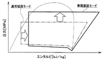
図6のモリエル線図に示すように、着霜遅延モードでは、通常暖房モードと比較して、冷凍サイクルの高圧側冷媒圧力が上昇した分、室外熱交換器15の入口側と出口側とのエンタルピ差が小さくなる。そのため、室外熱交換器15の吸熱量が減少するので、室外熱交換器15の着霜量が減少する。
As shown in the Mollier diagram of FIG. 6, in the frosting delay mode, compared to the normal heating mode, the increase in the refrigerant pressure on the high-pressure side of the refrigeration cycle is equivalent to the difference between the inlet side and the outlet side of the
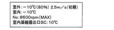
その結果、室外熱交換器15の着霜を遅らせることができるので、着霜遅延モードでは、通常暖房モードと比較して暖房性能の低下を抑制できる。図7に示す作動例では、通常暖房モードでは、30分経過後の暖房性能が最大暖房性能から55%に低下するのに対し、着霜遅延モードでは、30分経過後の暖房性能が最大暖房性能から29%しか低下しない。図8および図9は、図7の作動例における作動条件および各種機器の制御状態を示している。
As a result, since the frost formation of the
着霜遅延モードでは、送風機32の全送風量が通常暖房モードと同じになるので、車室内へ吹き出される吹出空気の風量を、通常暖房モード時と同じに維持できる。
In the frosting delay mode, the total amount of air blown from the
着霜遅延モードでは、通常暖房モードと比較して圧縮機11の回転数が上昇するので、車室内へ吹き出される吹出空気の温度を、通常暖房モード時と同じに維持できる。
In the frosting delay mode, the rotation speed of the
着霜遅延モードでは、第1膨張弁14へ流入する冷媒の過冷却度が目標過冷却度に近づくように第1膨張弁14の開度が制御されるので、サイクルの成績係数(COP)を最大値に近づけることができる。
In the frosting delay mode, the opening degree of the
除霜モードが決定された場合、冷房モードの冷媒流路に切り替える。これにより、室外熱交換器15に高温高圧冷媒を流して霜を融かすことができる。
When the defrost mode is determined, the refrigerant flow path is switched to the cooling mode. As a result, frost can be melted by flowing the high-temperature and high-pressure refrigerant through the
(B)冷房モード
冷房モードでは、制御装置40が、第1開閉弁17にて第2冷媒通路16を閉じる。さらに、第1膨張弁14にて第1冷媒通路13を全開状態とする。これにより、冷凍サイクル装置10では、図1の白抜矢印で示すように冷媒が流れる冷媒流路に切り替えられる。
(B) Cooling Mode In the cooling mode, the
この冷媒流路の構成で、制御装置40が、目標吹出温度TAO、センサ群の検出信号等に基づいて、制御装置40に接続された各種制御機器の作動状態、すなわち各種制御機器へ出力する制御信号を決定する。
With the configuration of the refrigerant flow path, the
例えば、圧縮機11の冷媒吐出能力、すなわち圧縮機11の電動モータ11bに出力される制御信号については、以下のように決定される。まず、目標吹出温度TAOに基づいて、予め制御装置40に記憶された制御マップを参照して、室内蒸発器20から吹き出される空気の目標蒸発器吹出温度TEOを決定する。したがって、制御装置40が実行する制御ルーチンのうち、この目標蒸発器吹出温度TEOを決定する制御ステップが目標蒸発器吹出温度決定手段を構成する。
For example, the refrigerant discharge capacity of the
そして、この目標蒸発器吹出温度TEOと蒸発器温度センサの検出値との偏差に基づいて、フィードバック制御手法を用いて室内蒸発器20を通過した空気の温度が、目標吹出温度TAOに近づくように圧縮機11の電動モータ11bに出力される制御信号が決定される。
Then, based on the deviation between the target evaporator blowout temperature TEO and the detected value of the evaporator temperature sensor, the temperature of the air that has passed through the
また、第2膨張弁19へ出力される制御信号については、第2膨張弁19へ流入する冷媒の過冷却度が、COPを最大値に近づけるように予め定められた目標過冷却度に近づくように決定される。
The control signal output to the
また、エアミックスドア36のサーボモータへ出力される制御信号については、エアミックスドア36が室内凝縮器12の空気通路を閉塞し、室内蒸発器20を通過後の空気の全流量が冷風バイパス通路35を通過するように決定される。
Regarding the control signal output to the servo motor of the
したがって、冷房モード時の冷凍サイクル装置10では、圧縮機11から吐出された高圧冷媒が室内凝縮器12に流入する。この際、エアミックスドア36が室内凝縮器12の空気通路を閉塞しているので、室内凝縮器12に流入した冷媒は、殆ど空気と熱交換することなく、室内凝縮器12から流出する。
Therefore, in the
室内凝縮器12から流出した冷媒は、第1冷媒通路13を介して第1膨張弁14に流入する。この際、第1膨張弁14が第1冷媒通路13を全開状態としているので、室内凝縮器12から流出した冷媒は、第1膨張弁14にて減圧されることなく、室外熱交換器15に流入する。そして、室外熱交換器15に流入した冷媒は、室外熱交換器15にて送風ファンから送風された外気へ放熱する。
The refrigerant that has flowed out of the
室外熱交換器15から流出した冷媒は、第3冷媒通路18を介して、第2膨張弁19へ流入して、第2膨張弁19にて低圧冷媒となるまで減圧膨張される。第2膨張弁19にて減圧された低圧冷媒は、室内蒸発器20に流入し、送風機32から送風された空気から吸熱して蒸発する。これにより、車室内へ送風される空気が冷却される。
The refrigerant flowing out of the
室内蒸発器20から流出した冷媒は、アキュムレータ21へ流入して気液分離される。そして、アキュムレータ21にて分離された気相冷媒が圧縮機11の吸入側から吸入されて再び圧縮機11にて圧縮される。なお、アキュムレータ21にて分離された液相冷媒は、サイクルが要求されている冷凍能力を発揮するために必要としていない余剰冷媒としてアキュムレータ21の内部に蓄えられる。
The refrigerant flowing out of the
以上の如く、冷房モードでは、エアミックスドア36にて室内凝縮器12の空気通路を閉塞しているので、室内蒸発器20にて冷却された空気を車室内へ吹き出すことができる。これにより、車室内の冷房を実現することができる。
As described above, in the cooling mode, the air passage of the
(C)除湿暖房モード
除湿暖房モードでは、制御装置40が第1開閉弁17にて第2冷媒通路16を閉じる。そして、第1、第2膨張弁14、19を絞り状態または全開状態とする。これにより、冷凍サイクル装置10は、冷房モードと同様に、図1の白抜横線矢印に示すように冷媒が流れる冷媒流路に切り替えられる。なお、除湿暖房モードでは、冷媒流れに対して室外熱交換器15と室内蒸発器20とが直列に接続されることとなる。
(C) Dehumidification heating mode In the dehumidification heating mode, the
この冷媒流路の構成で、制御装置40が、目標吹出温度TAO、目標凝縮器吹出温度TAVO、センサ群の検出信号等に基づいて、制御装置40に接続された各種制御機器の作動状態、すなわち各種制御機器へ出力する制御信号を決定する。
With this refrigerant flow path configuration, the
例えば、圧縮機11の電動モータ11bに出力される制御信号については、冷房モードと同様に決定される。また、エアミックスドア36のサーボモータへ出力される制御信号については、エアミックスドア36が冷風バイパス通路35を閉塞し、室内蒸発器20を通過後の空気の全流量が室内凝縮器12の空気通路を通過するように決定される。
For example, the control signal output to the
また、第1膨張弁14および第2膨張弁19については、車室内へ吹き出す吹出空気の目標温度である目標吹出温度TAOに基づいて演算される目標凝縮器吹出温度TAVOに応じて絞り開度が変更される。具体的には、制御装置40は、目標凝縮器吹出温度TAVOの上昇に伴って、第1膨張弁14にて第1冷媒通路13の通路面積を減少させるとともに、第2膨張弁19にて第3冷媒通路18の通路面積を増大させる。これにより、除湿暖房モードでは、第1モードから第4モードの4段階のモードを連続的に実行する。
The
第1モードでは、第1膨張弁14にて第1冷媒通路13を全開状態とし、第2膨張弁19を絞り状態とする。すなわち、サイクル構成については、冷房モードと全く同じ冷媒流路となるものの、エアミックスドア36は室内凝縮器12側の空気通路を全開状態とする。
In the first mode, the
これにより、室内凝縮器12では、圧縮機11から吐出された高圧冷媒が、室内蒸発器20にて冷却されて除湿された空気と熱交換して放熱する。これにより、車室内へ送風される空気が加熱される。
Thereby, in the
したがって、除湿暖房モードの第1モード時には、室内蒸発器20にて冷却され除湿された空気を、室内凝縮器12にて加熱して車室内へ吹き出すことができる。これにより、車室内の除湿暖房を実現することができる。
Therefore, in the first mode of the dehumidifying heating mode, the air cooled and dehumidified by the
第2モードでは、第1膨張弁14を絞り状態とし、第2膨張弁19の絞り開度を第1モード時よりも増加させた絞り状態とする。したがって、第2モードでは、第1モードに対して、室外熱交換器15へ流入する冷媒の温度を低下させることができる。したがって、室外熱交換器15における冷媒の温度と外気温との温度差を縮小して、室外熱交換器15における冷媒の放熱量を減少させることができる。
In the second mode, the
この結果、第1モード時に対して室内凝縮器12における冷媒の放熱量を増加させることができ、室内凝縮器12から吹き出される吹出空気の温度を上昇させることができる。
As a result, the heat radiation amount of the refrigerant in the
第3モードでは、第1膨張弁14の絞り開度を第2モード時よりも減少させた絞り状態とし、第2膨張弁19の絞り開度を第2モード時よりも増加させた絞り状態とする。
In the third mode, a throttle state in which the throttle opening of the
したがって、第3モードでは、室内凝縮器12から流出した冷媒は、第1冷媒通路13を介して第1膨張弁14に流入し、外気温よりも温度の低い中間圧冷媒となるまで減圧される。そして、第1膨張弁14にて減圧された中間圧冷媒は、室外熱交換器15に流入して、送風ファンから送風された外気から吸熱する。
Accordingly, in the third mode, the refrigerant that has flowed out of the
すなわち、第3モードでは、第1膨張弁14の絞り開度を減少させることによって、室外熱交換器15を、冷媒に吸熱させる吸熱器として機能させているので、第2モードよりも室内凝縮器12から吹き出される温度を上昇させることができる。
That is, in the third mode, the
この結果、第2モード時に対して室内凝縮器12における冷媒の放熱量を増加させることができ、室内凝縮器12から吹き出される吹出空気の温度を上昇させることができる。
As a result, the heat release amount of the refrigerant in the
第4モードでは、第1膨張弁14の絞り開度を第3モード時よりも減少させた絞り状態とし、第2膨張弁19にて第3冷媒通路18を全開状態とする。
In the fourth mode, the throttle opening of the
したがって、第4モードでは、第3モードに対して室外熱交換器15における冷媒蒸発温度を低下させることができ、室外熱交換器15における冷媒の吸熱量を増加させることができる。
Therefore, in the fourth mode, the refrigerant evaporation temperature in the
この結果、第3モードよりも室内凝縮器12から吹き出される吹出空気の温度を上昇させることができる。
As a result, the temperature of the blown air blown out from the
このように、除湿暖房モードでは、目標吹出温度TAOに基づいて演算される目標凝縮器吹出温度TAVOに応じて第1膨張弁14、第2膨張弁19の絞り開度を変更することで、車室内へ吹き出す吹出空気の温度を低温域から高温域までの広範囲に亘って調整することができる。
As described above, in the dehumidifying heating mode, the throttle opening degree of the
換言すると、除湿暖房モードでは、室外熱交換器15を、冷媒を放熱させる放熱器として機能させる状態から冷媒に吸熱させる蒸発器として機能させる状態へ切り替えながら、室外熱交換器15における冷媒の放熱量あるいは吸熱量を調整することができる。
In other words, in the dehumidifying heating mode, the amount of heat released from the refrigerant in the
したがって、室内凝縮器12における冷媒の放熱量を幅広い範囲で調整することができ、除湿運転時に空調対象空間へ吹き出される吹出空気の温度調整範囲を拡大させることができる。
Therefore, the heat radiation amount of the refrigerant in the
本実施形態では、ステップS402、S405で説明したように、制御装置40は、室外熱交換器15に着霜が生じている着霜状態、または着霜が懸念される着霜懸念状態であるか否かを判定し、着霜状態または着霜懸念状態であると判定した場合、着霜を遅らせるために冷媒の高圧側圧力を上昇させる着霜遅延制御を行う。
In the present embodiment, as described in steps S402 and S405, is the
これによると、図6に示すように、参照制御装置40が着霜遅延制御を行うと、冷媒の高圧側圧力が上昇することによって、室外熱交換器15の出口側冷媒と入口側冷媒とのエンタルピ差が小さくなる。その結果、室外熱交換器15の吸熱量が減少するので、室外熱交換器15の着霜を遅らせることができる。
According to this, as shown in FIG. 6, when the
本実施形態では、ステップS405で説明したように、制御装置40は、着霜遅延制御時、室内凝縮器12で加熱される空気の風量が減少するようにエアミックスドア36の作動を制御する。
In the present embodiment, as described in step S405, the
これによると、着霜遅延制御時、室内凝縮器12で加熱される空気の風量が減少することによって、冷媒の高圧側圧力を上昇させることができる。このとき、エアミックスドア36を利用して、室内凝縮器12で加熱される空気の風量を減少させるので、車室内に吹き出される空気の風量を維持できる。そのため、乗員の空調快適性を極力維持したまま、室外熱交換器15の着霜を遅らせることができる。
According to this, at the time of frost delay control, the high-pressure side pressure of the refrigerant can be increased by reducing the air volume of the air heated by the
本実施形態では、ステップS405で説明したように、制御装置40は、着霜遅延制御時、圧縮機11の回転数を、目標吹出温度TAOに対して決められる所定の回転数まで上昇させる。
In the present embodiment, as described in step S405, the
これによると、着霜遅延制御時、室外熱交換器15の吸熱量が減少しても目標吹出温度TAOの低下を抑制できる。そのため、乗員の空調快適性を極力維持したまま、室外熱交換器15の着霜を遅らせることができる。
According to this, at the time of frosting delay control, even if the heat absorption amount of the
本実施形態では、ステップS405で説明したように、制御装置40は、着霜遅延制御時、第1膨張弁14へ流入する冷媒の過冷却度が、サイクル成績係数COPを最大値に近づけるように定められた目標過冷却度に近づくように、第1膨張弁14の開度を決定する。
In the present embodiment, as described in step S405, the
これによると、着霜遅延制御時、冷媒の高圧側圧力を上昇させても、冷媒の過冷却度を目標過冷却度に近づけることができる。そのため、サイクル成績係数COPの低下を極力抑制しつつ、室外熱交換器15の着霜を遅らせることができる。
According to this, even when the high-pressure side pressure of the refrigerant is increased during the frosting delay control, the supercooling degree of the refrigerant can be brought close to the target supercooling degree. Therefore, frost formation of the
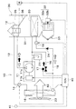
(第2実施形態)
上記第1実施形態では、圧縮機11から吐出された高圧冷媒を室内凝縮器12で空気に放熱するが、本実施形態では、図10に示すように、圧縮機11から吐出された高圧冷媒を冷媒熱媒体熱交換器25で熱媒体に放熱し、冷媒熱媒体熱交換器25で放熱された熱媒体をヒータコア34で空気に放熱する。例えば、熱媒体は、エチレングリコール系の不凍液、いわゆるLLCである。
(Second Embodiment)
In the first embodiment, the high-pressure refrigerant discharged from the
冷媒熱媒体熱交換器25およびヒータコア34は、圧縮機11から吐出された冷媒を放熱させるとともに、冷媒から放熱された熱を利用して空気を加熱する放熱手段である。ヒータコア34は、熱媒体と空気とを熱交換させるる熱媒体空気熱交換器である。
The refrigerant heat
ヒータコア34は、上記第1実施形態の室内凝縮器12の代わりに、室内空調ユニット30のケーシング31内に収容されている。ヒータコア34は、室内蒸発器20に対して空気の流れ方向下流側に配置されている。
The
冷風バイパス通路35は、室内蒸発器20を通過した空気をヒータコア34を迂回させて流す。エアミックスドア36は、ヒータコア34を通過させる空気と冷風バイパス通路35を通過させる空気との風量割合を調整する。
The cold
ヒータコア34は、熱媒体回路50を循環する熱媒体と空気とを熱交換させる加熱用熱交換器である。熱媒体回路50には、熱媒体を吸入して吐出するポンプ51が配置されている。ポンプ51の作動は、制御装置40によって制御される。
The
通常暖房モード時は、エアミックスドア36のサーボモータへ出力される制御信号については、上記第1実施形態と同様に、エアミックスドア36が冷風バイパス通路35を閉塞し、室内蒸発器20を通過後の空気の全流量がヒータコア34の空気通路を通過するように決定される。通常暖房モードでは、エアミックスドア36が最大暖房状態の位置に操作される。
In the normal heating mode, as for the control signal output to the servo motor of the
着霜遅延モード時は、エアミックスドア36のサーボモータへ出力される制御信号については、上記第1実施形態と同様に、エアミックスドア36が冷風バイパス通路35を所定量開け、室内蒸発器20を通過後の空気がヒータコア34の空気通路と冷風バイパス通路35とに分かれて通過するように決定される。着霜遅延モードでは、エアミックスドア36の開度が100%未満に決定される。
In the frosting delay mode, as with the control signal output to the servo motor of the
これにより、冷媒熱媒体熱交換器25の効率が低下してサイクル高圧が上昇するので、上記第1実施形態と同様の作用効果を奏することができる。
Thereby, since the efficiency of the refrigerant heat
(第3実施形態)
上記第2実施形態では、着霜遅延モード時、エアミックスドア36がヒータコア34の通過風量を減少させることによって、室外熱交換器15の着霜を遅延させるが、本実施形態では、図11、図12に示すように、着霜遅延モード時、ポンプ51が吐出する熱媒体の流量を減少させることによって、室外熱交換器15の着霜を遅延させる。
(Third embodiment)
In the second embodiment, in the frost delay mode, the
着霜遅延モード時は、制御装置40は、ポンプ51へ出力される制御信号については、通常暖房モード時の流量V1よりも少ない流量V2となるように決定する。着霜遅延モード時のポンプ吐出流量V2は、通常暖房モード時のポンプ吐出流量V1よりも少ない。
In the frosting delay mode, the
これにより、冷媒熱媒体熱交換器25を流れる熱媒体の流量が減少して冷媒熱媒体熱交換器25の効率が低下してサイクル高圧が上昇するので、上記第2実施形態と同様の作用効果を奏することができる。
As a result, the flow rate of the heat medium flowing through the refrigerant heat
本実施形態では、制御装置40は、着霜遅延制御時、ポンプ51が吐出する熱媒体の流量を減少させる。
In this embodiment, the
これによると、着霜遅延制御時、冷媒熱媒体熱交換器25を流れる熱媒体の流量が減少することによって、冷媒の高圧側圧力を上昇させることができる。そのため、室外熱交換器15の着霜を遅らせることができる。
According to this, at the time of frosting delay control, the high-pressure side pressure of the refrigerant can be increased by reducing the flow rate of the heat medium flowing through the refrigerant heat
(第4実施形態)
上記第3実施形態では、着霜遅延モード時、ポンプ51が吐出する熱媒体の流量を減少させることによって、室外熱交換器15の着霜を遅延させるが、本実施形態では、図13、図14に示すように、着霜遅延モード時、冷媒熱媒体熱交換器25をバイパスして熱媒体を流すことによって、室外熱交換器15の着霜を遅延させる。
(Fourth embodiment)
In the third embodiment, in the frost delay mode, the frost formation of the
熱媒体回路50は、バイパス流路52とバイパス切替弁53とを有している。バイパス流路52は、熱媒体が冷媒熱媒体熱交換器25をバイパスして流れる流路である。バイパス切替弁53は、バイパス流路52の開度を調整して、バイパス流路52を流れる熱媒体の流量を調整する調整手段である。バイパス切替弁53の作動は、制御装置40によって制御される。
The
通常暖房モード時は、制御装置40は、バイパス切替弁53へ出力される制御信号については、図13に示すように、バイパス流路52を閉じ、ポンプ51が吐出した熱媒体の全流量が冷媒熱媒体熱交換器25を通過するように決定される。
In the normal heating mode, the
着霜遅延モード時は、制御装置40は、バイパス切替弁53へ出力される制御信号については、図14に示すように、バイパス流路52を開き、ポンプ51が吐出した熱媒体が冷媒熱媒体熱交換器25とバイパス流路52とに分かれて通過するように決定される。
In the frosting delay mode, as shown in FIG. 14, the
これにより、冷媒熱媒体熱交換器25を流れる熱媒体の流量が減少して冷媒熱媒体熱交換器25の効率が低下してサイクル高圧が上昇するので、上記第2実施形態と同様の作用効果を奏することができる。
As a result, the flow rate of the heat medium flowing through the refrigerant heat
着霜遅延モード時、ヒータコア34を流れる熱媒体の流量は、通常暖房モード時と同じであるので、ヒータコア34から吹き出される空気の温度に温度分布が発生することを抑制できる。
Since the flow rate of the heat medium flowing through the
本実施形態では、制御装置40は、着霜遅延制御時、ポンプ51が吐出する熱媒体の流量を維持したまま、バイパス流路52を流れる熱媒体の流量が増加するように流量調整手段53の作動を制御する。
In the present embodiment, the
これによると、着霜遅延制御時、冷媒熱媒体熱交換器25を流れる熱媒体の流量が減少することによって、冷媒の高圧側圧力を上昇させることができる。このとき、バイパス流路52を利用して、冷媒熱媒体熱交換器25を流れる熱媒体の流量を減少させるので、ヒータコア34を流れる熱媒体の流量を維持できる。そのため、ヒータコア34から吹き出される空気の温度分布を抑制しつつ、室外熱交換器15の着霜を遅らせることができる。
According to this, at the time of frosting delay control, the high-pressure side pressure of the refrigerant can be increased by reducing the flow rate of the heat medium flowing through the refrigerant heat
(他の実施形態)
上記実施形態を適宜組み合わせ可能である。上記実施形態を例えば以下のように種々変形可能である。
(Other embodiments)
The above embodiments can be combined as appropriate. The above embodiment can be variously modified as follows, for example.
(1)上述の各実施形態では、暖房モードと冷房モードおよび除湿暖房モードをエアコンスイッチの操作信号によって切り替える例について説明したが、これに限定されない。例えば、操作パネルに各運転モードを設定する運転モード設定スイッチを設け、当該運転モード設定スイッチの操作信号に応じて、暖房モードと冷房モードおよび除湿暖房モードを切り替えるようにしてもよい。 (1) In each of the above-described embodiments, the example in which the heating mode, the cooling mode, and the dehumidifying heating mode are switched by the operation signal of the air conditioner switch is described, but the present invention is not limited to this. For example, an operation mode setting switch for setting each operation mode may be provided on the operation panel, and the heating mode, the cooling mode, and the dehumidifying heating mode may be switched according to an operation signal of the operation mode setting switch.
(2)上述の各実施形態では、車両用空調装置1をハイブリッド車両に搭載しているが、これに限定されず、車両用空調装置1を電気自動車等の種々の車両に搭載してもよい。 (2) In each of the embodiments described above, the vehicle air conditioner 1 is mounted on the hybrid vehicle. However, the present invention is not limited to this, and the vehicle air conditioner 1 may be mounted on various vehicles such as an electric vehicle. .
11 圧縮機
12 室内凝縮器(放熱手段)
14 第1膨張弁(減圧手段)
15 室外熱交換器(吸熱手段)
32 送風機(送風手段)
36 エアミックスドア
40 制御装置(制御手段)
11
14 First expansion valve (pressure reduction means)
15 Outdoor heat exchanger (heat absorption means)
32 Blower (Blower means)
36
Claims (5)
冷媒を圧縮して吐出する圧縮機(11)と、
前記圧縮機(11)から吐出された前記冷媒を放熱させるとともに、前記冷媒から放熱された熱を利用して前記空気を加熱する放熱手段(12、25、34)と、
前記放熱手段(12、25、34)で放熱された前記冷媒を減圧させる減圧手段(14)と、
前記減圧手段(14)で減圧された前記冷媒に外気から吸熱させる吸熱手段(15)と、
前記吸熱手段(15)に着霜が生じている着霜状態、または着霜が懸念される着霜懸念状態であるか否かを判定し、前記着霜状態または前記着霜懸念状態であると判定した場合、前記着霜を遅らせるために前記冷媒の高圧側圧力を上昇させる着霜遅延制御を行う制御手段(40)と、
熱媒体が循環する熱媒体回路(50)と、
前記熱媒体を吸入して吐出するポンプ(51)とを備え、
前記放熱手段(12、25、34)は、前記圧縮機(11)から吐出された前記冷媒を前記熱媒体に放熱させる冷媒熱媒体熱交換器(25)と、前記熱媒体と前記空気とを熱交換させる熱媒体空気熱交換器(34)とを有しており、
前記制御手段(40)は、前記着霜遅延制御時、前記ポンプ(51)が吐出する前記熱媒体の流量を減少させることを特徴とする車両用空調装置。 A blowing means (32) for blowing air toward the passenger compartment;
A compressor (11) for compressing and discharging the refrigerant;
Heat radiating means (12, 25, 34) for radiating the refrigerant discharged from the compressor (11) and heating the air using heat radiated from the refrigerant;
Decompression means (14) for decompressing the refrigerant radiated by the heat radiation means (12, 25, 34);
An endothermic means (15) for causing the refrigerant decompressed by the decompression means (14) to absorb heat from outside air;
It is determined whether the heat absorption means (15) is in a frosting state where frost is generated or a frosting concern state in which frost formation is a concern, and is in the frosting state or the frosting concern state. If it is determined, control means (40) for performing frost delay control for increasing the high-pressure side pressure of the refrigerant in order to delay the frost formation ;
A heat medium circuit (50) through which the heat medium circulates;
A pump (51) for sucking and discharging the heat medium,
The heat radiating means (12, 25, 34) includes a refrigerant heat medium heat exchanger (25) that radiates the refrigerant discharged from the compressor (11) to the heat medium, and the heat medium and the air. A heat medium air heat exchanger (34) for heat exchange,
The said control means (40) reduces the flow volume of the said heat medium which the said pump (51) discharges at the time of the said frost formation delay control, The air conditioner for vehicles characterized by the above-mentioned .
冷媒を圧縮して吐出する圧縮機(11)と、 A compressor (11) for compressing and discharging the refrigerant;
前記圧縮機(11)から吐出された前記冷媒を放熱させるとともに、前記冷媒から放熱された熱を利用して前記空気を加熱する放熱手段(12、25、34)と、 Heat radiating means (12, 25, 34) for radiating the refrigerant discharged from the compressor (11) and heating the air using heat radiated from the refrigerant;
前記放熱手段(12、25、34)で放熱された前記冷媒を減圧させる減圧手段(14)と、 Decompression means (14) for decompressing the refrigerant radiated by the heat radiation means (12, 25, 34);
前記減圧手段(14)で減圧された前記冷媒に外気から吸熱させる吸熱手段(15)と、 An endothermic means (15) for causing the refrigerant decompressed by the decompression means (14) to absorb heat from outside air;
前記吸熱手段(15)に着霜が生じている着霜状態、または着霜が懸念される着霜懸念状態であるか否かを判定し、前記着霜状態または前記着霜懸念状態であると判定した場合、前記着霜を遅らせるために前記冷媒の高圧側圧力を上昇させる着霜遅延制御を行う制御手段(40)と、 It is determined whether the heat absorption means (15) is in a frosting state where frost is generated or a frosting concern state in which frost formation is a concern, and is in the frosting state or the frosting concern state. If it is determined, control means (40) for performing frost delay control for increasing the high-pressure side pressure of the refrigerant in order to delay the frost formation;
熱媒体が循環する熱媒体回路(50)と、 A heat medium circuit (50) through which the heat medium circulates;
前記熱媒体を吸入して吐出するポンプ(51)とを備え、 A pump (51) for sucking and discharging the heat medium,
前記放熱手段(12、25、34)は、前記圧縮機(11)から吐出された前記冷媒を前記熱媒体に放熱させる冷媒熱媒体熱交換器(25)と、前記熱媒体と前記空気とを熱交換させる熱媒体空気熱交換器(34)とを有しており、 The heat radiating means (12, 25, 34) includes a refrigerant heat medium heat exchanger (25) that radiates the refrigerant discharged from the compressor (11) to the heat medium, and the heat medium and the air. A heat medium air heat exchanger (34) for heat exchange,
前記熱媒体回路(50)は、前記熱媒体が前記冷媒熱媒体熱交換器(25)をバイパスして流れるバイパス流路(52)と、前記バイパス流路(52)を流れる前記熱媒体の流量を調整する流量調整手段(53)とを有しており、 The heat medium circuit (50) includes a bypass channel (52) through which the heat medium flows bypassing the refrigerant heat medium heat exchanger (25), and a flow rate of the heat medium through the bypass channel (52). Flow rate adjusting means (53) for adjusting
前記制御手段(40)は、前記着霜遅延制御時、前記ポンプ(51)が吐出する前記熱媒体の流量を維持したまま、前記バイパス流路(52)を流れる前記熱媒体の流量が増加するように前記流量調整手段(53)の作動を制御することを特徴とする車両用空調装置。 The control means (40) increases the flow rate of the heat medium flowing through the bypass passage (52) while maintaining the flow rate of the heat medium discharged from the pump (51) during the frosting delay control. Thus, the operation of the flow rate adjusting means (53) is controlled as described above.
前記制御手段(40)は、前記着霜遅延制御時、前記放熱手段(12、25、34)で加熱される前記空気の風量が減少するように前記エアミックスドア(36)の作動を制御することを特徴とする請求項1または2に記載の車両用空調装置。 An air mix door (36) for adjusting the ratio of the air volume of the air heated by the heat dissipating means (12, 25, 34) and the remaining air volume of the air volume of the air blowing means (32);
The control means (40) controls the operation of the air mix door (36) so that the air volume of the air heated by the heat dissipation means (12, 25, 34) decreases during the frosting delay control. The vehicle air conditioner according to claim 1 or 2 .
Priority Applications (5)
| Application Number | Priority Date | Filing Date | Title |
|---|---|---|---|
| JP2015156200A JP6332193B2 (en) | 2015-08-06 | 2015-08-06 | Air conditioner for vehicles |
| CN201680045644.XA CN107848374B (en) | 2015-08-06 | 2016-07-22 | Air conditioner for vehicle |
| US15/743,615 US10538138B2 (en) | 2015-08-06 | 2016-07-22 | Air conditioning device for vehicle |
| PCT/JP2016/071517 WO2017022512A1 (en) | 2015-08-06 | 2016-07-22 | Air conditioning device for vehicle |
| DE112016003578.0T DE112016003578T5 (en) | 2015-08-06 | 2016-07-22 | Air conditioning device for a vehicle |
Applications Claiming Priority (1)
| Application Number | Priority Date | Filing Date | Title |
|---|---|---|---|
| JP2015156200A JP6332193B2 (en) | 2015-08-06 | 2015-08-06 | Air conditioner for vehicles |
Publications (3)
| Publication Number | Publication Date |
|---|---|
| JP2017035901A JP2017035901A (en) | 2017-02-16 |
| JP2017035901A5 JP2017035901A5 (en) | 2017-07-27 |
| JP6332193B2 true JP6332193B2 (en) | 2018-05-30 |
Family
ID=57942882
Family Applications (1)
| Application Number | Title | Priority Date | Filing Date |
|---|---|---|---|
| JP2015156200A Active JP6332193B2 (en) | 2015-08-06 | 2015-08-06 | Air conditioner for vehicles |
Country Status (5)
| Country | Link |
|---|---|
| US (1) | US10538138B2 (en) |
| JP (1) | JP6332193B2 (en) |
| CN (1) | CN107848374B (en) |
| DE (1) | DE112016003578T5 (en) |
| WO (1) | WO2017022512A1 (en) |
Families Citing this family (13)
| Publication number | Priority date | Publication date | Assignee | Title |
|---|---|---|---|---|
| JP6418779B2 (en) * | 2014-05-08 | 2018-11-07 | サンデンホールディングス株式会社 | Air conditioner for vehicles |
| JP6277888B2 (en) * | 2014-06-27 | 2018-02-14 | 株式会社デンソー | Refrigeration cycle equipment |
| JP6738157B2 (en) * | 2016-02-26 | 2020-08-12 | サンデン・オートモーティブクライメイトシステム株式会社 | Vehicle air conditioner |
| CN106705352B (en) * | 2016-11-25 | 2019-05-24 | 重庆美的通用制冷设备有限公司 | The control method and device of electric expansion valve in a kind of air conditioner and its defrosting |
| KR20180096894A (en) * | 2017-02-22 | 2018-08-30 | 한온시스템 주식회사 | Air conditioner for vehicles |
| US11009247B2 (en) * | 2017-06-27 | 2021-05-18 | Mitsubishi Electric Corporation | Air conditioner |
| CN110631204A (en) * | 2018-06-25 | 2019-12-31 | 青岛海尔空调器有限总公司 | Defrosting control method and device for air conditioner |
| CN110631189A (en) * | 2018-06-25 | 2019-12-31 | 青岛海尔空调器有限总公司 | Defrosting control method and device for air conditioner |
| IT201800007165A1 (en) * | 2018-07-13 | 2020-01-13 | Air-water heat pump with water bypass during the defrost cycle. | |
| JP7164986B2 (en) * | 2018-07-31 | 2022-11-02 | サンデン株式会社 | Vehicle air conditioner |
| CN110006134B (en) * | 2018-12-29 | 2020-06-26 | 西安交通大学 | Air conditioning system and control method and device thereof |
| CN114459138B (en) * | 2022-02-25 | 2023-12-12 | 智己汽车科技有限公司 | Air conditioner control method and equipment with autonomous heating blower |
| CN115264760A (en) * | 2022-07-08 | 2022-11-01 | 珠海格力电器股份有限公司 | Air conditioner control method and device and air conditioner |
Family Cites Families (25)
| Publication number | Priority date | Publication date | Assignee | Title |
|---|---|---|---|---|
| JPH0678045B2 (en) * | 1985-07-03 | 1994-10-05 | 株式会社日立製作所 | Air mix door control device for automobile air conditioners |
| US5605051A (en) * | 1991-04-26 | 1997-02-25 | Nippondenso Co., Ltd. | Automotive air conditioner having condenser and evaporator provided within air duct |
| JP3538845B2 (en) * | 1991-04-26 | 2004-06-14 | 株式会社デンソー | Automotive air conditioners |
| US5309731A (en) * | 1991-12-27 | 1994-05-10 | Nippondenso Co., Ltd. | Air conditioning apparatus |
| US5598887A (en) * | 1993-10-14 | 1997-02-04 | Sanden Corporation | Air conditioner for vehicles |
| JPH09142139A (en) * | 1995-09-22 | 1997-06-03 | Denso Corp | Air-conditioning device for vehicle |
| US5735133A (en) * | 1996-04-12 | 1998-04-07 | Modine Manufacturing Co. | Vehicular cooling system with thermal storage |
| JP3767050B2 (en) * | 1996-12-02 | 2006-04-19 | 株式会社デンソー | Air conditioner for vehicles |
| JP3794078B2 (en) * | 1996-12-05 | 2006-07-05 | 株式会社デンソー | Air conditioner for vehicles |
| JP3952545B2 (en) * | 1997-07-24 | 2007-08-01 | 株式会社デンソー | Air conditioner for vehicles |
| JP2001324237A (en) * | 2000-05-12 | 2001-11-22 | Denso Corp | Equipment for refrigerating cycle |
| DE10128164A1 (en) * | 2001-06-09 | 2002-12-12 | Behr Gmbh & Co | Vehicle cooling system for a temperature-increasing device and method for cooling the temperature-increasing device |
| JP2004189213A (en) * | 2002-11-28 | 2004-07-08 | Matsushita Electric Ind Co Ltd | Operating device of refrigerant cycle and operating method of refrigerant cycle |
| JP4232463B2 (en) * | 2003-01-09 | 2009-03-04 | 株式会社デンソー | Air conditioner |
| US10160291B2 (en) * | 2011-01-21 | 2018-12-25 | Sanden Holdings Corporation | Vehicle air conditioning apparatus |
| EP2679421B1 (en) * | 2011-02-21 | 2019-11-13 | Hitachi, Ltd. | Vehicle air conditioning system |
| JP5944135B2 (en) * | 2011-10-17 | 2016-07-05 | サンデンホールディングス株式会社 | Air conditioner for vehicles |
| CN103158490B (en) * | 2011-12-19 | 2016-05-25 | 杭州三花研究院有限公司 | A kind of automotive air-conditioning system |
| JP2014058239A (en) | 2012-09-18 | 2014-04-03 | Denso Corp | Air conditioner for vehicle |
| JP5895787B2 (en) | 2012-09-24 | 2016-03-30 | 株式会社デンソー | Air conditioner for vehicles |
| JP6108066B2 (en) | 2012-10-31 | 2017-04-05 | 三菱自動車工業株式会社 | Air conditioner for vehicles |
| JP6005484B2 (en) * | 2012-11-09 | 2016-10-12 | サンデンホールディングス株式会社 | Air conditioner for vehicles |
| JP6003874B2 (en) * | 2013-01-23 | 2016-10-05 | 株式会社デンソー | Air conditioner for vehicles |
| JP6192434B2 (en) * | 2013-08-23 | 2017-09-06 | サンデンホールディングス株式会社 | Air conditioner for vehicles |
| JP2015156200A (en) | 2014-01-16 | 2015-08-27 | 朝日機材株式会社 | Electric machinery tool with robbery prevention function |
-
2015
- 2015-08-06 JP JP2015156200A patent/JP6332193B2/en active Active
-
2016
- 2016-07-22 WO PCT/JP2016/071517 patent/WO2017022512A1/en active Application Filing
- 2016-07-22 US US15/743,615 patent/US10538138B2/en not_active Expired - Fee Related
- 2016-07-22 DE DE112016003578.0T patent/DE112016003578T5/en not_active Withdrawn
- 2016-07-22 CN CN201680045644.XA patent/CN107848374B/en active Active
Also Published As
| Publication number | Publication date |
|---|---|
| US10538138B2 (en) | 2020-01-21 |
| JP2017035901A (en) | 2017-02-16 |
| CN107848374B (en) | 2020-05-22 |
| CN107848374A (en) | 2018-03-27 |
| WO2017022512A1 (en) | 2017-02-09 |
| US20180201088A1 (en) | 2018-07-19 |
| DE112016003578T5 (en) | 2018-05-30 |
Similar Documents
| Publication | Publication Date | Title |
|---|---|---|
| JP6332193B2 (en) | Air conditioner for vehicles | |
| JP6493370B2 (en) | Heat pump system | |
| JP6332560B2 (en) | Air conditioner for vehicles | |
| JP6011375B2 (en) | Refrigeration cycle equipment | |
| JP5445569B2 (en) | Air conditioner for vehicles | |
| JP2019209938A (en) | Refrigeration cycle device for vehicle | |
| CN109890636B (en) | Refrigeration cycle device | |
| JP2018091536A (en) | Refrigeration cycle device | |
| WO2013145537A1 (en) | Air conditioner device for vehicle | |
| JP2019006330A (en) | Air conditioner | |
| WO2018096869A1 (en) | Vehicle air conditioning device | |
| JP5935714B2 (en) | Refrigeration cycle equipment | |
| WO2017187790A1 (en) | Coolant quantity insufficiency sensing device and refrigeration cycle device | |
| JP6375796B2 (en) | Refrigeration cycle equipment | |
| JP6601307B2 (en) | Refrigeration cycle equipment | |
| JP6544287B2 (en) | Air conditioner | |
| JP6369237B2 (en) | Air conditioner | |
| WO2017130845A1 (en) | Heat pump system | |
| WO2022038951A1 (en) | Refrigeration cycle device | |
| WO2023248868A1 (en) | Heat pump cycle apparatus | |
| JP6672999B2 (en) | Air conditioner | |
| WO2018003352A1 (en) | Refrigeration cycle device | |
| JP6387873B2 (en) | Refrigeration cycle equipment | |
| JP2014000905A (en) | Heat pump cycle |
Legal Events
| Date | Code | Title | Description |
|---|---|---|---|
| A521 | Request for written amendment filed |
Free format text: JAPANESE INTERMEDIATE CODE: A523 Effective date: 20170614 |
|
| A621 | Written request for application examination |
Free format text: JAPANESE INTERMEDIATE CODE: A621 Effective date: 20170615 |
|
| TRDD | Decision of grant or rejection written | ||
| A01 | Written decision to grant a patent or to grant a registration (utility model) |
Free format text: JAPANESE INTERMEDIATE CODE: A01 Effective date: 20180403 |
|
| A61 | First payment of annual fees (during grant procedure) |
Free format text: JAPANESE INTERMEDIATE CODE: A61 Effective date: 20180416 |
|
| R151 | Written notification of patent or utility model registration |
Ref document number: 6332193 Country of ref document: JP Free format text: JAPANESE INTERMEDIATE CODE: R151 |
|
| R250 | Receipt of annual fees |
Free format text: JAPANESE INTERMEDIATE CODE: R250 |
|
| R250 | Receipt of annual fees |
Free format text: JAPANESE INTERMEDIATE CODE: R250 |
|
| R250 | Receipt of annual fees |
Free format text: JAPANESE INTERMEDIATE CODE: R250 |