JP6329151B2 - Banding device - Google Patents
Banding device Download PDFInfo
- Publication number
- JP6329151B2 JP6329151B2 JP2015532526A JP2015532526A JP6329151B2 JP 6329151 B2 JP6329151 B2 JP 6329151B2 JP 2015532526 A JP2015532526 A JP 2015532526A JP 2015532526 A JP2015532526 A JP 2015532526A JP 6329151 B2 JP6329151 B2 JP 6329151B2
- Authority
- JP
- Japan
- Prior art keywords
- tension
- gear
- band
- banding
- motor
- Prior art date
- Legal status (The legal status is an assumption and is not a legal conclusion. Google has not performed a legal analysis and makes no representation as to the accuracy of the status listed.)
- Active
Links
- 230000033001 locomotion Effects 0.000 claims description 104
- 230000007246 mechanism Effects 0.000 claims description 69
- 230000002572 peristaltic effect Effects 0.000 claims description 65
- 238000003466 welding Methods 0.000 claims description 43
- 238000010168 coupling process Methods 0.000 claims description 36
- 238000005859 coupling reaction Methods 0.000 claims description 36
- 238000000034 method Methods 0.000 claims description 36
- 230000008878 coupling Effects 0.000 claims description 35
- 230000008569 process Effects 0.000 claims description 34
- 238000004804 winding Methods 0.000 claims description 31
- 238000005520 cutting process Methods 0.000 claims description 14
- 230000005540 biological transmission Effects 0.000 claims description 10
- 238000012546 transfer Methods 0.000 claims description 10
- 238000010438 heat treatment Methods 0.000 claims description 2
- 238000012856 packing Methods 0.000 claims 1
- 230000002093 peripheral effect Effects 0.000 description 11
- 238000006243 chemical reaction Methods 0.000 description 10
- 230000009471 action Effects 0.000 description 9
- 239000004033 plastic Substances 0.000 description 7
- 230000006870 function Effects 0.000 description 4
- 230000010355 oscillation Effects 0.000 description 4
- 238000003825 pressing Methods 0.000 description 4
- 239000000155 melt Substances 0.000 description 3
- 238000005096 rolling process Methods 0.000 description 3
- 238000000926 separation method Methods 0.000 description 3
- 239000004743 Polypropylene Substances 0.000 description 2
- 230000008859 change Effects 0.000 description 2
- 238000001816 cooling Methods 0.000 description 2
- 229920000728 polyester Polymers 0.000 description 2
- 229920001155 polypropylene Polymers 0.000 description 2
- 238000013459 approach Methods 0.000 description 1
- 230000008901 benefit Effects 0.000 description 1
- 230000015572 biosynthetic process Effects 0.000 description 1
- 230000001419 dependent effect Effects 0.000 description 1
- 230000005611 electricity Effects 0.000 description 1
- 238000002474 experimental method Methods 0.000 description 1
- 238000005304 joining Methods 0.000 description 1
- 238000012423 maintenance Methods 0.000 description 1
- 230000007257 malfunction Effects 0.000 description 1
- 238000004806 packaging method and process Methods 0.000 description 1
- -1 polypropylene Polymers 0.000 description 1
- 230000009467 reduction Effects 0.000 description 1
- 230000004044 response Effects 0.000 description 1
- 230000000630 rising effect Effects 0.000 description 1
- 238000003860 storage Methods 0.000 description 1
- 230000007704 transition Effects 0.000 description 1
Images


Classifications
-
- B—PERFORMING OPERATIONS; TRANSPORTING
- B65—CONVEYING; PACKING; STORING; HANDLING THIN OR FILAMENTARY MATERIAL
- B65B—MACHINES, APPARATUS OR DEVICES FOR, OR METHODS OF, PACKAGING ARTICLES OR MATERIALS; UNPACKING
- B65B13/00—Bundling articles
- B65B13/18—Details of, or auxiliary devices used in, bundling machines or bundling tools
- B65B13/22—Means for controlling tension of binding means
-
- B—PERFORMING OPERATIONS; TRANSPORTING
- B65—CONVEYING; PACKING; STORING; HANDLING THIN OR FILAMENTARY MATERIAL
- B65B—MACHINES, APPARATUS OR DEVICES FOR, OR METHODS OF, PACKAGING ARTICLES OR MATERIALS; UNPACKING
- B65B13/00—Bundling articles
- B65B13/02—Applying and securing binding material around articles or groups of articles, e.g. using strings, wires, strips, bands or tapes
- B65B13/025—Hand-held tools
-
- B—PERFORMING OPERATIONS; TRANSPORTING
- B65—CONVEYING; PACKING; STORING; HANDLING THIN OR FILAMENTARY MATERIAL
- B65B—MACHINES, APPARATUS OR DEVICES FOR, OR METHODS OF, PACKAGING ARTICLES OR MATERIALS; UNPACKING
- B65B13/00—Bundling articles
- B65B13/18—Details of, or auxiliary devices used in, bundling machines or bundling tools
- B65B13/185—Details of tools
- B65B13/187—Motor means
-
- B—PERFORMING OPERATIONS; TRANSPORTING
- B65—CONVEYING; PACKING; STORING; HANDLING THIN OR FILAMENTARY MATERIAL
- B65B—MACHINES, APPARATUS OR DEVICES FOR, OR METHODS OF, PACKAGING ARTICLES OR MATERIALS; UNPACKING
- B65B13/00—Bundling articles
- B65B13/18—Details of, or auxiliary devices used in, bundling machines or bundling tools
- B65B13/24—Securing ends of binding material
- B65B13/32—Securing ends of binding material by welding, soldering, or heat-sealing; by applying adhesive
- B65B13/322—Friction welding
Description
本発明は、梱包品に巻き付けバンドを巻き付けるための、バンド掛け装置、特に持ち運び可能なバンド掛け装置に関するものであって、巻き付けバンドのループにバンドテンションをもたらすテンション装置を有し、テンション装置にテンション軸を中心に動力で回転駆動可能な、巻き付けバンド内へ係合するために設けられた、テンションギアが設けられており、テンション装置が更に、テンションプレートを有しており、テンション装置によって実施される引張りプロセスの間に、巻き付けバンドの一部がテンションギアとテンションプレートの間に位置し、テンションギアともテンションプレートとも接触しており、更に、テンションギア又はテンションプレートが、搖動軸を中心に動力で揺動可能な搖動部材上に配置されており、それによって搖動部材の揺動によりテンションギアとテンションプレートの間の間隔が増大されるか、又は減少される。バンド掛け装置は、更に、結合、特に摩擦溶接結合又は他の溶接結合を形成するための、溶接装置のような、結合装置を有しており、その結合装置によって巻き付けバンドのループの互いに重なり合った2つの領域において、溶接部材を用いて巻き付けバンドの局所的な加熱をもたらすことができる。 The present invention relates to a banding device for winding a winding band around a packaged product, and more particularly to a portable banding device, which has a tensioning device that provides band tension to a loop of the winding band, and A tension gear is provided, which is provided for engaging in a winding band, which can be driven by rotation around the shaft, and the tension device further comprises a tension plate and is implemented by the tension device. During the tensioning process, a part of the wrapping band is located between the tension gear and the tension plate, is in contact with the tension gear and the tension plate, and the tension gear or tension plate is driven around the peristaltic axis. It is arranged on a swinging member that can swing with Or the spacing between the tension gear and the tension plate is increased by the swinging of the swinging member by, or is reduced. The banding device further comprises a coupling device, such as a welding device, for forming a coupling, in particular a friction welding coupling or other welding coupling, by which the loops of the winding band overlap each other. In two areas, a welding member can be used to provide local heating of the wrapping band.
この種の持ち運びできるバンド掛け装置は、梱包物にプラスチックバンドを巻き付けるために使用される。そのために、梱包品の回りにそれぞれのプラスチックバンドのループがかけられる。その場合に、通常、プラスチックバンドはストックロールから引き出される。梱包物の回りにループが完全に巻き付けられた後に、バンドの端部領域がバンドループの一部と重なる。バンドのこの2層の領域にバンド掛け装置が添接され、その場合にバンドが巻き付け方向に締め付けられて、テンション装置によってバンドループにバンドテンションがもたらされ、摩擦溶接(又は他の結合技術)によって2つのバンド層の間のループにおいて締結がもたらされる。その場合に、バンドループの2つの端部の領域内で振動運動する摩擦シューによりバンドが押圧される。圧力と運動によって生じる熱が、通常プラスチックを有するバンドを短時間局所的に溶融する。それによって2つのバンド層の間に、永続的な結合であるが大きい力によって再び外れる結合が生じる。実質的に同時に、又はその後に、ループがストックロールから分離される。それによって、それぞれの梱包物にはバンドが掛けられている。 This type of portable banding device is used to wrap plastic bands around packages. For this purpose, a loop of each plastic band is put around the package. In that case, the plastic band is usually drawn from the stock roll. After the loop is completely wrapped around the package, the end region of the band overlaps with a portion of the band loop. A banding device is attached to these two layers of the band, in which case the band is clamped in the winding direction and the tensioning device provides band tension to the band loop and friction welding (or other joining technique) Provides a fastening in the loop between the two band layers. In that case, the band is pressed by a friction shoe that oscillates in the region of the two ends of the band loop. The heat generated by the pressure and motion melts the band, usually with plastic, for a short time locally. This creates a bond between the two band layers that is a permanent bond but is released again by a large force. At substantially the same time or thereafter, the loop is separated from the stock roll. Thereby, a band is hung on each package.
種概念に基づくバンド掛け装置は、持ち運んで使用するために設けられており、その場合に装置はユーザーによってそれぞれの使用場所へ携行されて、そこでは外部から供給される供給エネルギを頼ることはできない。この種のバンド掛け装置を使用するために必要な、任意の梱包物の回りの巻き付けバンドを締め付け、締結をもたらすためのエネルギは、前に知られているバンド掛け装置においては、通常、電気的な蓄電池により、又は圧縮空気によって提供される。このエネルギによって、テンション装置によってバンドにもたらされるバンドテンションと巻き付けバンドにおける締結がもたらされる。種概念に基づくバンド掛け装置は、更に、そのために設けられている、溶接のみ可能なプラスチックバンドを互いに結合しなければならない。 The banding device based on the seed concept is provided for carrying and using, in which case the device is carried by the user to the respective place of use, where the supplied energy supplied from outside cannot be relied upon . The energy required to use this type of banding device to tighten and wrap the wrapping band around any package is typically electrical in a previously known banding device. Provided by a fresh storage battery or by compressed air. This energy results in band tension provided to the band by the tensioning device and fastening in the wrapping band. The banding device based on the seed concept must also connect the weldable plastic bands provided for it together.
持ち運びできる装置においては、バンド掛け装置のユーザーが装置を使用する際に身体的な負荷をできるだけ受けないようにするために、重量がわずかであることが、特に重要である。同様に、人間工学的理由から、特にバンド掛け装置のヘッド領域に重量が集中することを回避するために、バンド掛け装置全体に重量ができるだけ均一に分配されなければならない。この種の集中は、装置の不利な操作特性をもたらす。更に、常に、バンド掛け装置のできるだけ人間工学的かつ操作しやすい取扱いが望まれる。特に誤操作と誤機能の可能性は、できるだけ小さくなければならない。 In portable devices, it is particularly important that the weight of the banding device is small so that the user of the banding device receives as little physical load as possible when using the device. Similarly, for ergonomic reasons, the weight should be distributed as evenly as possible throughout the banding device, in particular to avoid concentrating the weight on the head area of the banding device. This type of concentration results in a disadvantageous operating characteristic of the device. Furthermore, it is always desirable to handle the banding device as ergonomically and as easy to operate as possible. In particular, the possibility of erroneous operation and malfunction must be as small as possible.
したがって本発明の課題は、バンド巻き付けを少なくとも自動化して迅速に行うことが可能である一方、高い機能安全性と良好な操作特性を有する、冒頭で挙げた種類の概念に基づくバンド掛け装置を提供することである。しかしこの課題は、持ち運びできるバンド掛け装置のみに向けられたものではない。 Accordingly, an object of the present invention is to provide a banding device based on the concept of the type mentioned at the beginning, which is capable of at least automating and rapidly performing band winding, while having high functional safety and good operating characteristics. It is to be. However, this problem is not only directed to portable banding devices.
この課題は、冒頭で挙げた種類のバンド掛け装置において、本発明によれば、唯一のモータによって解決され、そのモータの、同一の回転方向における駆動運動により、巻き付けバンドを締め付けるテンションギアが回転可能であり、また、搖動部材も、テンションギアとテンションプレートとの間の間隔を揺動運動によって変化させ、特に増大させるために、モータにより、又は空気式に駆動されて、搖動軸を中心に揺動することができる。 This problem is solved by the present invention in a banding device of the type mentioned at the beginning, according to the present invention, and the tension gear for tightening the winding band can be rotated by the drive movement of the motor in the same rotational direction. In addition, the peristaltic member is also driven by a motor or pneumatically to change the distance between the tension gear and the tension plate by a swinging motion, and in particular to increase it, swinging about the peristaltic shaft. Can move.
本発明に係る解決によれば、唯一のモータしか必要とされず、したがってテンションギアによるバンドの締め付けも、テンション装置の搖動部材の持ち上げも、それぞれ1つのモータ運動によって行うことができる。本発明によれば、その場合に、好ましくは電気モータとして形成されたモータの同一の1つの回転方向を利用することができる。したがって本発明は、唯一のモータによって実施可能な機能の拡張を可能にし、その利点は、持ち運びできるバンド掛け装置において特別に効力を発揮する。本発明に係る実施形態において、搖動部材の揺動又は持ち上げは、もはや手動ではなく、動力で行われるので、本発明の好ましい実施形態において、これまでは常にテンションギアの搖動部材を移動させるために必要であった、手動操作されるレバーと、レバーからテンションギアへの伝達機構を省くことができる。したがって本発明は、バンド掛け装置におけるより高い自動化程度を可能にするだけでなく、より高い自動化にもかかわらず、この種の持ち運びできるバンド掛け装置の重量の削減も可能にする。 According to the solution according to the invention, only a single motor is required, so that the tightening of the band by the tension gear and the lifting of the peristaltic member of the tension device can each be carried out by one motor movement. According to the invention, it is possible in this case to utilize the same rotational direction of the motor, preferably formed as an electric motor. Thus, the present invention allows for the expansion of functions that can be performed by a single motor, and its advantages are particularly effective in portable banding devices. In the embodiment according to the present invention, the swinging or lifting of the peristaltic member is no longer done manually but by power, so in the preferred embodiment of the present invention, in order to always move the peristaltic member of the tension gear. The manually operated lever and the transmission mechanism from the lever to the tension gear can be omitted. Thus, the present invention not only allows for a higher degree of automation in the strapping device, but also allows for a reduction in the weight of this type of portable strapping device despite the higher automation.
本発明によれば、更に、バンド掛け装置内のモータの数の削減が可能であるだけではない。本発明の好ましい実施形態においては、少なくとも実質的に完全に自動化されたバンド掛けプロセスも可能になり、それにおいて溶接装置とそれをバンド上へ送り、又は移送すること、及びバンドのストックから締結されたバンドループの分だけバンドを切り離すことも、バンド掛け装置の唯一のモータの駆動運動によって行われる。唯一のモータによって引張りプロセスも、溶接位置への溶接装置の移送も、更に溶接シューの駆動と切断カッターの駆動も行われる、バンド掛け装置は、特許文献1から知られている。これをもって特許文献1を上述した解決に関して参照し、参照によってその内容が取り入れられる。
According to the invention, it is not only possible to reduce the number of motors in the banding device. In a preferred embodiment of the present invention, an at least substantially fully automated banding process is also possible, in which the welding device and its transfer or transfer onto the band, and fastening from the band stock. The separation of the band by the amount of the band loop is also performed by the only motor driving movement of the banding device. A banding device is known from US Pat. No. 6,057,056, in which the pulling process is performed by a single motor, the welding device is transferred to the welding position, the welding shoe and the cutting cutter are also driven. With this,
本発明の好ましい実施形態においては、ギア機構内、特にテンション装置のギア機構内でテンションギアへのモータの作用結合か、又は搖動部材へのモータの作用結合が交互に形成可能である。この解決においては、好ましくは少なくとも1つの切り替えプロセスによって、搖動部材との、又はテンションギアとの電気モータの作用結合が形成され、したがって2つの機能のそれぞれ一方のみが実施される。切り替えプロセスは特に簡単に、すなわちわずかな構造的手間と費用によって実現されるので、この種の解決は、純粋に機械的に、そしてそれにもかかわらず重量を削減して機能的に安全に実施することができる。 In a preferred embodiment of the invention, the working coupling of the motor to the tension gear or the working coupling of the motor to the peristaltic member can be alternately formed in the gear mechanism, in particular in the gear mechanism of the tension device. In this solution, preferably, at least one switching process forms an operative coupling of the electric motor with the peristaltic member or with the tension gear, so that only one of the two functions is carried out. Since the switching process is realized in a particularly simple manner, i.e. with little structural effort and cost, this kind of solution is implemented purely mechanically and nevertheless with reduced weight and functional safety be able to.
少なくとも1つの切り替えプロセスは、好ましい実施形態においては、停止装置の2つのクランプ装置によって行うことができ、それらが交互にテンション装置のギア機構のそれぞれ少なくとも1つのギア機構部材とブロックするように係合可能であり、それによってそれぞれのギア機構部材のブロックにより、モータによってもたらされる駆動運動の同一の回転方向を有する動力の駆動運動が、テンションギアへ、又は昇降運動の形式で搖動部材へ伝達される。テンション装置のギア機構として、特に1段又は多段のプラネットギア機構を設けることができる。したがってクランプ装置は、本発明のこの種の実施形態において、プラネットギア機構の2つのギア機構部材へ効果的に作用する。 The at least one switching process can, in a preferred embodiment, be carried out by two clamping devices of the stop device, which engage so that they alternately block with at least one gear mechanism member of the tension device gear mechanism, respectively. It is possible, by means of which blocks of the respective gear mechanism members are transmitted to the tension gear or to the peristaltic member in the form of a lifting movement, with a power drive movement having the same rotational direction of the drive movement provided by the motor. . As the gear mechanism of the tension device, in particular, a one-stage or multi-stage planet gear mechanism can be provided. The clamping device thus effectively acts on the two gear mechanism members of the planet gear mechanism in this type of embodiment of the invention.
揺動運動を発生させるための、構造的に特に手間のかからない解決において、回転運動に対してブロックされた、プラネットギア機構のギア機構部材は、搖動軸を中心に回転可能なギア機構部材を支持するためにも設けられており、そのギア機構部材によって好ましくはモータの駆動運動もテンションギアへ伝達される。したがってこの種の解決においては、プラネットギア機構は、テンションギアの駆動運動のためにも、搖動部材の駆動運動のためにも、利用することができる。この種の解決は、2つの機能のために必要な、極めて多様な伝導にもかかわらず、特にわずかな数の構成部品で十分である。 The gear mechanism member of the planet gear mechanism, which is blocked against rotational movement, supports the gear mechanism member that can rotate around the peristaltic axis in a structurally trouble-free solution for generating rocking motion. The drive mechanism of the motor is also preferably transmitted to the tension gear by the gear mechanism member. Therefore, in this type of solution, the planet gear mechanism can be used both for the driving movement of the tension gear and for the driving movement of the peristaltic member. This type of solution is particularly sufficient with only a few components, despite the extremely diverse conduction required for the two functions.
自立した重要性も有する、本発明の特に好ましい他の実施形態において、唯一のモータの動力駆動運動は、巻き付けバンドを締め付ける際のテンションギアの駆動のため、及び搖動部材の駆動のための他に、テンションギア及び/又は搖動部材を締め付けるべきバンド上にバンドテンションに依存して可変に押圧し、又は圧接するためにも、設けることができる。バンドテンションに依存する圧接と、それに伴ってバンドに対するテンション装置の圧接力がバンドテンションに依存して増大することも、自立した重要性を有することができる。その場合に依存性は、バンドテンションが上昇する場合に、テンションギアからもたらされる圧接力も上昇するように、定められている。バンドテンションが上昇する場合には、テンションギアとバンドの間にスリップが生じる危険も増大するので、圧接力を増大させる措置によってスリップの危険に対抗作用することができる。その場合に、締め付ける場合と同じモータ回転方向が使用されると、特に効果的である。バンドを締め付ける場合の動力駆動運動は、好ましくは、巻き付けバンド内へ進入してバンドテンションに抗して回転するテンションギアによる巻き付けバンドの引張りプロセスの間、巻き付けバンドからテンションギアに作用する反力が、テンションプレートの方向におけるテンションギアの押圧力又はテンションギアの方向におけるテンションプレートの押圧力を増大させるように、利用することができる。 In another particularly preferred embodiment of the invention, which also has a self-supporting importance, the only motor-driven movement of the motor is for driving the tension gear when tightening the winding band and for driving the peristaltic member. Depending on the band tension, the tension gear and / or the peristaltic member can also be variably pressed or pressed against the band to be tightened. It is also possible for the pressure contact depending on the band tension and the accompanying increase in the pressure contact force of the tension device against the band to be dependent on the band tension. In this case, the dependency is determined so that when the band tension increases, the pressure contact force generated from the tension gear also increases. When the band tension rises, the risk of slippage between the tension gear and the band also increases, so that the risk of slippage can be countered by measures that increase the pressure contact force. In that case, it is particularly effective if the same motor rotation direction as in the case of tightening is used. The power drive movement when tightening the band is preferably the reaction force acting on the tension gear from the winding band during the tensioning process of the winding band by the tension gear that enters into the winding band and rotates against the band tension. It can be used to increase the pressing force of the tension gear in the direction of the tension plate or the pressing force of the tension plate in the direction of the tension gear.
本発明の他の視点によれば、わずかな構造的手間により、簡単な操作性において、バンドテンションからもたらされて、ギア機構内へ反作用する力を保持し、緩めることができ、それによって駆動運動がテンションギアへ伝達されることが、可能にされなければならない。特許請求項1の対象と組み合わせても、自立しても、重要性を有することができる、本発明のこの他の視点のための解決は、特許請求項8に記載されている。したがって本発明は、バンド掛け装置内で使用するための停止装置に関するものであり、その停止装置によって回転可能な、駆動運動を伝達するために設けられているギア、特にバンド掛け装置のテンション装置のギア機構ギアをクランプすることができる。本発明に係る停止装置は、揺動軸を中心に揺動可能、かつギアに対して間隔をもって配置された少なくとも1つのクランプボディを持たなければならず、そのクランプボディは解放位置から停止位置へ揺動可能であり、その停止位置において、−好ましくはアーチ形状の接触面の一部をもって−ギアの実質的に平坦な、従って形状結合部材をもたない周クランプ面に添接し、その場合にクランプボディは、ギアの周クランプ面に対するクランプボディの揺動軸の間隔よりも大きい揺動半径を有しており、かつ揺動軸を中心とするクランプボディの回転方向は、解放位置からクランプ位置へ移動する場合に、クランプすべきギアとは逆の回転方向に延びている。
According to another aspect of the invention, it is possible to hold and loosen the force that comes from the band tension and reacts into the gear mechanism in a simple operability with little structural effort, thereby driving It must be possible for movement to be transmitted to the tension gear. A solution for this other aspect of the invention, which can be of importance, whether combined with the subject matter of
この種の停止装置によって、構造的に簡単なやり方で、回転するギア機構ギアの機能的に極めて安全なロックを行うことができる。ギアの回転方向におけるロックは、わずかな力の消費で維持することができる。クランプボディのクランプ力は、自動的に上昇するが、トルクの上昇によってギアを更に回転させるように試みなければならない。 This kind of stop device makes it possible to provide a functionally very safe lock of the rotating gear mechanism gear in a structurally simple manner. Locking in the rotational direction of the gear can be maintained with little power consumption. Although the clamping force of the clamp body increases automatically, an attempt must be made to further rotate the gear by increasing the torque.
本発明に係る停止装置は、特にギア機構のギアを緩めることができるように停止するために効果的に利用することができ、そのギアは、駆動運動をバンド掛け装置のテンション装置のテンションギアへ伝達するギア機構に属している。それは、特に、駆動運動をテンションギアへ伝達するプラネットギア機構のギアをクランプするために設けることができる。クランプすべきギアのクランプにより、又はそれを利用しながら、好ましくはギア機構の少なくとも2つの従動方向の1つ、特にテンションギアへのギア機構の従動方向を定めることができるので、バンドを締め付けることができる。 The stop device according to the present invention can be effectively used to stop the gear mechanism in particular so that the gear of the gear mechanism can be loosened, and the gear moves to the tension gear of the tension device of the banding device. It belongs to the transmission gear mechanism. It can be provided in particular for clamping the gear of the planet gear mechanism that transmits the drive movement to the tension gear. Tightening the band by means of clamping the gear to be clamped or using it, preferably one of at least two driven directions of the gear mechanism, in particular the driven direction of the gear mechanism to the tension gear Can do.
更に、好ましくは、クランプを緩めることにより、テンションギアとギア機構に作用するバンドテンションも少なくとも部分的に、好ましくは完全に取り去られる。この種の停止装置は、バンドテンション値が高い場合でもクランプを無効にするために比較的わずかな緩め力しか必要としないので、本発明によって特に機能的に安全かつ簡単に操作されるバンド掛け装置が得られる。小さい取扱い力又は操作力が、搖動レバーを省くことを許し、その搖動レバーによってこれまでは、前に知られているバンド掛け装置において、締め付けられたバンドから搖動部材を持ち上げるために高いモーメントが発生されていた。長い搖動レバーの代わりに、押しボタン又はキーを利用することができ、それによってテンションを緩めるプロセスが行われる。 Furthermore, preferably, by loosening the clamp, the tension gear and the band tension acting on the gear mechanism are also at least partially, preferably completely removed. This type of stop device requires a relatively slight loosening force to deactivate the clamp even when the band tension value is high, so that the banding device which is particularly functionally safe and easy to operate according to the invention Is obtained. A small handling force or operating force allows the peristaltic lever to be omitted, which in the past has generated a high moment to lift the peristaltic member from the clamped band in previously known banding devices. It had been. Instead of a long peristaltic lever, a push button or key can be used, thereby performing the process of releasing the tension.
本発明の他の好ましい形態が、請求項、明細書及び図面から明らかにされる。 Other preferred forms of the invention will be apparent from the claims, specification and drawings.
純粋に図式的に図に示す実施例を用いて、本発明を詳細に説明する。 The invention will be described in detail with the aid of an embodiment shown purely diagrammatically.
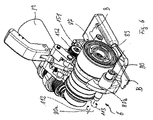
図1と2に示す、手動でのみ操作される、本発明に係るバンド掛け器具1は、ハウジング2を有しており、そのハウジングがバンド掛け器具を包囲し、そのハウジングに器具を操作するためのグリップ3が形成されている。バンド掛け器具には、更にベースプレート4が設けられており、その下側は、梱包すべき対象上に配置するために設けられている。ベースプレート4及びベースプレートと結合された、詳しく図示されない、バンド掛け器具の支持体に、バンド掛け器具1のすべての機能ユニットが固定されている。
The
バンド掛け器具1によって、図1には詳細に図示されない、前もって梱包すべき対象の回りに巻かれた、たとえばポリプロピレン(PP)又はポリエステル(PET)からなるプラスチックバンドBのループを、バンド掛け器具のテンション装置6を用いて締め付けることができる。そのためにテンション装置6は、テンションギア7を有しており、そのテンションギアによって、引張りプロセスのためにバンドBを捕捉することができる。テンションギア7は、揺動可能な搖動部材8に配置されており、その搖動部材は搖動部材の搖動軸8aを中心に揺動することができる。搖動部材の搖動軸8aに対して間隔をもって配置された回転軸を有するテンションギア7は、搖動部材の搖動軸8aを中心とする搖動部材8の揺動運動によって、ベースプレート4に取り付けられた、好ましくは湾曲したテンションプレート9に対して距離を有する一方の終端位置から第2の終端位置へ移動することができ、その第2の終端位置においてテンションギア7がテンションプレート9に対して押圧される。テンションギア7は、搖動部材の搖動軸8aを中心に逆の回転方向に然るべく動力駆動で運動することによって、テンションプレート9から遠ざかって、その初期位置へ揺動して戻ることができ、それによってテンションギア7とテンションプレート9の間にあるバンドが、取り出すために自由にされる。
A loop of plastic band B made of, for example, polypropylene (PP) or polyester (PET), wrapped around the object to be packed in advance, not shown in detail in FIG. It can be tightened using the tension device 6. For this purpose, the tension device 6 has a tension gear 7, by means of which the band B can be captured for the tensioning process. The tension gear 7 is disposed on a swingable swinging member 8, and the swinging member can swing around a swinging shaft 8a of the swinging member. The tension gear 7 having a rotation shaft disposed at a distance from the swinging shaft 8a of the swinging member is preferably attached to the
テンション装置の図示の実施形態の使用において、巻き付けバンドの2つの層がテンションギア7とテンションプレートの間に位置し、テンションギア7によってテンションプレートに対して押圧される。その場合に、テンションギア7の回転によって、バンドループに梱包目的のために十分に高いバンドテンションを与えることが可能である。締め付けのプロセス及びそのために好ましいやり方で形成されているテンション装置と搖動部材8を、以下で更に詳細に説明する。 In use of the illustrated embodiment of the tension device, the two layers of the wrapping band are located between the tension gear 7 and the tension plate and are pressed against the tension plate by the tension gear 7. In that case, the rotation of the tension gear 7 can give the band loop a sufficiently high band tension for packaging purposes. The tightening process and the tensioning device and the peristaltic member 8 which are formed in a preferred manner for that are described in more detail below.
次に、バンドループの、バンドの2つの層が重なり合う箇所において、それ自体知られたやり方で、バンド掛け器具の摩擦溶接装置12によって2つの層の溶接を行うことができる。それによってバンドループは、永続的に締結することができる。ここに示す好ましい実施例において、摩擦溶接及び分離装置12は、バンド掛け器具の同一の1つのモータMによって駆動することができ、そのモータによって他のすべての動力駆動される運動も実施される。そのために、既知のやり方で、モータMから動力駆動運動の箇所への伝達方向に、詳しく図示されないフリーホィールが設けられており、それによって、駆動運動がそれぞれそのために設けられている駆動回転方向においてバンド掛け器具の該当する機能ユニットへ伝達されて、それぞれそのために設けられている、モータの他の駆動回転方向に伝達は行われない。
The two layers can then be welded by the banding tool
そのために、摩擦溶接装置12には、著しく図式的に示されるだけの溶接シュー13が設けられており、その溶接シューが移送装置14によってバンドに対して距離を有する休止位置から溶接位置へ移動されて、その溶接位置において溶接シューがバンドに対して押圧される。その際に機械的な圧力によって巻き付けバンド上に押圧される溶接シュー及び同時に行われる所定の周波数を有する溶接シューの振動運動が、巻き付けバンドの2つの層を溶融する。バンドBの局所的に可塑化ない溶融された領域が互いに流動して、その後バンドBの冷却後に、2つのバンド層の間に結合が生じる。必要な限りにおいて、その後、バンドループをバンドのストックロールから、バンド掛け器具1の詳しく図示されない切断装置によって切り離すことができる。
For this purpose, the
テンションギア7をテンションプレート9の方向に送り届け、テンション軸6aを中心にテンションギア7を回転駆動し、テンションプレートからテンションギアを持ち上げ、摩擦溶接装置12の移送装置14によって摩擦溶接装置12を送り届けて、摩擦溶接装置12それ自体も使用し、切断装置を操作することは、共通の電気的なモータMのみを使用しながら行われ、そのモータはバンド掛け器具のこれらのコンポーネントのためにそれぞれ駆動運動を提供する。モータMに電流を供給するために、バンド掛け器具に交換可能かつ特に充電するために取り外し可能なアキュムレータ15が配置されており、そのアキュムレータは電気的エネルギを蓄えるために用いられる。たとえば圧縮空気又は他の電気のような、他の外部補助エネルギの供給を設けることができるが、図1と2に示すバンド掛け器具においては行われない。
The tension gear 7 is delivered in the direction of the tension plate 9, the tension gear 7 is driven to rotate around the tension shaft 6 a, the tension gear is lifted from the tension plate, and the
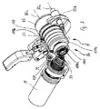
図4に示すように、本発明に係るバンド掛け器具においては、モータMの駆動軸の2つの箇所において、その駆動運動がテンション装置6のため、又は摩擦溶接装置12のために、取り出される。モータMは、そのために、2つの回転方向の各々において駆動することができる。テンション装置6へ、又は摩擦溶接装置12へ、駆動運動の伝達を交代することは、モータMの駆動軸上に配置されている(詳しく図示されない)フリーホィールによって、モータの駆動軸の回転方向に従って自動的に行われる。駆動軸の一方の回転方向において、駆動運動はテンション装置6へ伝達される。その場合にフリーホィールに基づいて、摩擦溶接装置12は駆動運動を行わない。他の回転方向においては、テンション装置6は駆動運動なしで、摩擦溶接装置12が駆動される。動力駆動運動の伝達方向を変更するために、場合によって手動で行うべき切替えプロセスは、この実施形態においては、不要である。この種のフリーホィールは、バンド掛け装置に関連して前もって知られており、従ってそれについて詳しく説明しない。
As shown in FIG. 4, in the banding device according to the present invention, the driving motion is taken out for the tension device 6 or the
同様に図4に示すように、摩擦溶接装置12と移送装置14への駆動運動の動力的な伝達は、適切な手段によって行われる。それは、たとえば、リング状に閉成された歯付きベルトを有する歯付きベルトドライブとすることができ、その歯付きベルトが2つの歯車を介して案内されている。2つの歯車の一方が、電気モータMの駆動軸上に配置されており、他方は摩擦溶接装置12のギア機構に属し、そのギア機構によって動力駆動運動が移送装置14も摩擦溶接装置12の溶接シュー13も移動させる。それによって巻き付けバンドの互いに重なり合う2つの層へ押圧された溶接シューは、所定の周波数と振幅で振動運動することができ、その振動運動によって溶接シューの領域内の2つのバンド層が局所的に溶融されて、それに続く冷却によって互いに溶接される。
Similarly, as shown in FIG. 4, the power transmission of the driving motion to the
モータの駆動軸上で、モータMから見て溶接装置のための歯付きベルトドライブの後方に傘歯車19が配置されており、その傘歯車は、それと歯合する第2の傘歯車20と同様に、テンション装置の傘歯車ギア機構に属する。第2の傘歯車20が配置されているのと同じ軸上に、他の歯付きベルトドライブ22の第1の歯車21も配置されており、その歯付きベルトドライブは更に、第2の歯車23を介して案内されている。歯付きベルトドライブ22の第1の歯車21は、軸24上に相対回動不能に配置されている。
On the drive shaft of the motor, a
軸24の他方の端部上に、バンド掛け器具の搖動部材8が差し嵌められており、それはテンション装置6の構成部分であって、テンションギア7も、テンションギア7の前段に接続されたギア機構、ここではプラネットギア機構26も支持しており、そのために搖動部材8に、適切な軸受箇所を設けることができる。搖動部材8は軸24上に、軸24の長手軸を中心に揺動可能に配置され、軸承されるように、差し嵌められている。したがって軸24の長手軸は、同時に搖動部材の搖動軸8aであって、それを中心に搖動部材8が揺動可能である。
On the other end of the
プラネットギア機構26は、1段又は多段のプラネットギア機構として、特に2段又は3段のプラネットギア機構として、形成することができる。歯車23のテンションギア7を向いた前側から、プラネットギア機構26に属する入力側の外歯切りのサンギア30が突出しており、その回転軸は、入力側の歯車23の回転軸6aと同一である。歯車23の軸(実施例においてこの軸にサンギア30も形成されている)上にフリーホィール45が配置されており、そのフリーホィールはサンギア30の一方の回転方向、すなわちサンギアの駆動用に設けられている回転方向のみを許す。サンギア30は、リングギア27を通り、プラネット支持体25の中央の切り欠きを通して案内されており、それらも同様にプラネットギア機構26の構成部分である。プラネットギアの入力側から見て、プラネット支持体25はプラネットギア機構26の、テンション軸6aに相当する軸上でリングギア27の後方に配置されている。プラネット支持体は、クランプギア、カップリングギア又は平歯車となるように、形成することもできる。
The
リングギア27は、その外周面にカム27cを有しており、そのカムが、バンド掛け装置のベースプレート4に固定された支持部46と係合する。その場合に内歯切りのリングギア27は、次のように、すなわちカム27cが支持部46内への、たとえば支持部の切り欠き46a内への係合の内部で、わずかな相対移動を実施することができるように、支持される。リングギア27は、更に、リング形状の突出部27aを有し、その上に、プラネットギア機構26を軸承するための転がり軸受28が配置されている。
The ring gear 27 has a
その軸がテンション軸6aと整合するプラネット支持体25の3つのプラネットギア25bが、プラネットギア機構26の入力側のリングギア27の内歯切りと歯合する。プラネット支持体25のプラネットギア25bは、更に、サンギア30と歯合し、そのサンギアから駆動運動を吸収して、リングギア27へ、然るべく減速して伝達することができる。したがってプラネット支持体25が相対回動不能に配置される場合に、サンギア30の回転運動をリングギア27の回転運動に変換することができる。実施例において、停止装置の第1のクランプ29が揺動可能なカムとして形成されており、それがプラネット支持体25の外周面に設けられたクランプ面25aと接触可能であり、又はそれから距離をもって離れるように揺動することができる。その場合にカムは、次のように、すなわちカムがクランプ面25aと接触した場合に入力側のプラネット支持体25の回転によって、プラネット支持体25のために設けられている回転方向にクランプ作用が更に強化されるように、配置されている。然るべき切り替えプロセスに基づいてカムをクランプ面25a上へ送り届けることによって、プラネット支持体25を回転に対してブロックすることができる。同様に切り替えプロセスによって、カム29をクランプ面25aから遠ざけて、それによってプラネット支持体25を回転運動するように解放することができる。その場合に切り替えプロセスは、切り替え軸143を中心とするクランプ29の揺動運動を作動させることができ、その切り替えプロセスは、押しボタン44の操作によって作動される。
The three planet gears 25b of the planet support 25 whose axes are aligned with the tension shaft 6a mesh with the internal gear cutting of the ring gear 27 on the input side of the
サンギア30は、更に、リングギア32の回転軸31の領域内に配置されており、そのリングギアの歯切りのない外側面32aが第2のクランプ33に対応づけられている。回転軸31は、テンション軸6aと同一であり、又はそれと整合している。外側面32aと協働するクランプ33は、原理において第1のクランプ29と同様に、2つの終端位置の間で移動することができる、切り替え可能なカムとして形成することができ、その場合に一方の位置において、リングギア32が回転に対してブロックされ、他方の位置においては回転運動のために解放される。更にリングギア32の内歯切りが3つのプラネットギア34と歯合し、それらは後続のプラネット支持体35の、リングギア32へ向いた前側に軸承されている。プラネット支持体35のプラネットギア34は、リングギア32内へ突出する、入力側の歯車23のサンギア30と歯合している。
The
記載された好ましい実施形態において、停止装置は、ギア25、32の常に一方、そして一方のみが回転を停止され、それぞれ他方のギア25、32は回転運動のために自由であるように、設計されている。従って停止装置29、33の位置に従って、一方で、歯車23とサンギア30の回転運動が、リングギア32の内歯切り内のプラネットギア34の移動に基づいて、テンション軸6aと回転軸31を中心とするプラネット支持体25の回転をもたらすことが、可能である。或いは、サンギア30の回転が、停止装置の位置に従ってリングギア32の回転をもたらす。プラネット支持体25が停止装置によってクランプされていない場合に、回転するサンギアがプラネットギア25bを連動させて、プラネット支持体25は回転し、リングギア27は固定位置に留まる。それに対してリングギア32がクランプされていない場合には、リングギア32の回転がプラネットギア34の連動をもたらし、そのプラネットギアがリングギア32を回転運動させる。プラネットギア機構26がテンションギア7へ向かって更に推移して回転に対する抵抗が、リングギア32を回転させるために克服すべきトルクよりも大きくなるので、この場合には特にリングギア32が回転し、テンションギア7は実質的に回転しない。
In the preferred embodiment described, the stop device is designed so that one and only one of the gears 25, 32 is always stopped from rotation and the other gear 25, 32 is free for rotational movement, respectively. ing. Therefore, according to the position of the
プラネット支持体35の、テンションギア7へ向いた他の前側において、このプラネット支持体に相対回動不能に他のサンギア36が配置されており、そのサンギアが他のプラネット支持体42のプラネットギア41と歯合する。テンションギア7へ向けられた、プラネット支持体42と相対回動不能に結合された他のサンギア43が、リングギアとして形成された他のプラネット支持体37の切り欠きに挿通されている。サンギア43は、他のプラネット支持体37の、テンションギア7へ向いたプラネットギア38と歯合している。第2のプラネット支持体37のプラネットギア38は、テンションギア7の内歯切りと歯合して、そのテンションギアをテンション軸6aを中心に回転運動させる。その外周面に細かい歯切り(図示せず)を有するテンションギア7のこの回転運動は、周面によってバンドBを捕捉して、バンドループのバンドを引き戻すために利用され、それによってバンドループ内のバンドのテンションが増大される。
On the other front side of the planet support 35 facing the tension gear 7, another
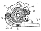
第3のプラネット支持体37は、その外側面に突出部37aを有しており、その突出部が回転運動によってストッパ部材39に接触することができる。ストッパ部材39自体は、搖動部材にではなく、ベースプレート4又はその他の支持体に固定されており、その支持体は搖動部材8の揺動運動に関与しない。したがってストッパ部材39は、突出部37aに関して位置固定されている。
The
梱包物にバンドを掛ける場合の使用において、バンド掛け器具1は、次のように振る舞う:それぞれの梱包物の回りに市場で一般的なプラスチック巻き付けバンドを有するバンドループが巻き付けられた後に、そのバンド端部のバンドループが部分的に二重になっている領域がバンド掛け器具内へ挿入されて、バンド端部がバンド掛け器具内の詳しく図示されないバンドクランプによって保持される。バンドBの、バンドループに直接連続する部分が、テンション装置6のテンションプレート9の上方に二重にして載置される。その場合に、テンションギア7と前段に接続されたギア機構26とを有する搖動部材8は、その上方の終端位置にあって、その位置においてテンションギア7がテンションプレート9に対して間隔(その定められている最大の間隔)をもって配置されており、それによってできるだけ大きい開口間隙が生じ、それが、テンション装置内へバンドを簡単、快適かつそれに伴って迅速に挿入することを可能にする。次に、搖動部材がテンションギア7と対向するテンションプレート9上に下降されて、テンションプレート9とテンションギア7との間に配置されたバンドに対して押圧される。テンションギアのこの移送運動も、引張りプロセスの開始時にテンションギアからバンドへもたらされる圧接力の高さも、本発明の上述した実施形態において、1つ又は複数のばね部材44(図示せず)によって発生させることができる。押しボタン10の操作によって、ばね部材を解放して、次々と実施されるプロセス部分「締め付け」、「締結発生」「切断」、テンション装置の領域内でバンドテンションを緩める、及び「搖動部材を持ち上げる」を作動させることができ、そのために、好ましくは、バンド掛け器具の操作者がそれ以上の進入を行う必要はない。
In use in the case of banding a package, the
テンションギア7が自動的に開放位置からその締め付け位置(図10内の締め付け位置と図11内の開放位置を参照)へ移動されて、そこでバンドB上に載置されて、バンドを介してテンションプレート9上に押圧された後に、動力による駆動運動がテンションギア7へ伝達される。そして、第2のクランプ33が、リングギア32を押圧する位置へ移動される。それによってリングギア32は、回転運動に対してロックされて、停止される。それに対して第1のクランプ29は、更に、入力側のプラネット支持体25に対して距離をもって位置決めされており、回転運動のためにリングギア27を解放する。モータMの予め定められた回転方向に基づいて傘歯車機構19、20、21を介して第2の歯付きベルトドライブ22とそれに伴って歯車23へ伝達される動力駆動運動が、ここで後に挙げるギア機構部材の順序において入力側の歯車23、サンギア30、プラネットギア34、サンギア36、プラネットギア41、サンギア43を介し、プラネットギア38を介してテンションギア7へ達する。テンションギア7は、特に、多段のプラネットギア機構により著しく減速されたモータの回転運動において、−それに伴って必要な場合にはそれなりに高いトルクで−所定の回転方向に駆動することができる。
The tension gear 7 is automatically moved from the open position to its tightening position (see the tightening position in FIG. 10 and the open position in FIG. 11), where it is placed on the band B and tensioned via the band. After being pressed onto the plate 9, the driving motion by the power is transmitted to the tension gear 7. Then, the
上述した駆動状態、バンド掛け器具の「締め付け」において、バンドと係合している、駆動されるテンションギア7によって、それぞれ、バンドテンションからもたらされ、反力としてテンションギアに作用する抵抗力に従って、テンションギア7に、逆方向に作用する然るべき反力が生じる。この反力は、動力の駆動運動とは逆の伝達方向において、多段のプラネットギア機構の、駆動運動の伝達に関与するすべてのギア機構部材へ作用する。1段又は多段のプラネットギア機構とは異なるギアタイプが使用される場合に、これにおいても、すでにもたらされているバンドテンションからもたらされて、テンションギアとの接触を介してそれぞれのギアへ導入される反力が、本発明の主旨における利用のために提供される。本発明によれば、この反力は、方法条件、特にもたらすべきバンドテンションが高い場合においても、機能安全性を改良するために、使用することができる。したがって、この反力を以下で説明する目的に利用するために、原理的に、これらのギア機構部材の各々をそのために、特にこれらのギア機構部材の各々において上述した反力を取り出して、使用することが可能である。 In the driving state described above, in the “clamping” of the banding device, the driven tension gear 7 engaged with the band respectively results from the band tension and follows the resistance force acting on the tension gear as a reaction force. The tension gear 7 has a suitable reaction force acting in the opposite direction. This reaction force acts on all gear mechanism members involved in the transmission of the driving motion of the multistage planetary gear mechanism in the transmission direction opposite to the driving motion of the power. If a gear type different from the one-stage or multi-stage planetary gear mechanism is used, this will still result from the band tension already provided to each gear via contact with the tension gear. The reaction force introduced is provided for use within the spirit of the invention. According to the invention, this reaction force can be used to improve the functional safety even in the process conditions, in particular when the band tension to be brought about is high. Therefore, in order to use this reaction force for the purpose described below, in principle, each of these gear mechanism members is used for that purpose, in particular by taking out the reaction force described above in each of these gear mechanism members. Is possible.
そのために、実施例においてはプラネット支持体37が使用される。その場合にプラネット支持体37が、ストッパ部材39を介してベースプレート4上に支持され、それによってテンション装置6全体が搖動軸8aを中心に抵抗力(バンドテンション)に比例してバンド上に押圧される。したがってテンションギア7は、バンドテンションに比例してバンドB上に押圧される。引張りプロセスによって発生されるバンドテンションは、バンドテンションが連続的に上昇する場合に、好ましいやり方で、バンドBへのテンションギア7の圧接力も増大させるために利用され、それによって、バンドテンションが上昇する場合にそれ自体同様に増大する、引張りプロセスにおけるテンションギア7の「滑り抜け」又はスリップの危険に対抗作用することができる。
For this purpose, a
プラネット支持体には、そのために、位置固定のストッパ部材39と協働する、進入部材37aが形成されている。カムとして形成されて、プラネット支持体の外周に配置され、そこから実質的に径方向に張り出す進入部材は、ストッパ部材39に支持される。特に図3から明らかなように、固定位置のストッパ部材39は、そのために、バンド掛け器具のヘッド端部の領域内に位置している。ストッパ部材39は、図示の実施例においてテンション軸6aの一方の側に、すなわちヘッド側の端部に位置しており、それに対して実質的に平行に延びる搖動部材の搖動軸8aは、テンション軸6aの他方の側に位置している。搖動部材8は、少なくとも引張りプロセスの間揺動可能であり、すなわち揺動運動に対してブロックされておらず、そのために解放されており、その搖動部材にはプラネット支持体37が転がり軸受を介してテンション軸6aを中心に回転可能に配置されている。更に、プラネット支持体37は、引張りプロセスの間テンション軸6aを中心に回転可能である。引張りプロセスに対する反応としてバンドB内に発生されるバンドテンションは、引張りプロセスにおいて定められたテンションギアの回転方向とは逆の力をテンションギア7へもたらす。この反応力は、テンションギアからプラネット支持体37を介して搖動部材8へ、搖動部材の搖動軸8aを中心とする向きのトルクをもたらし、そのトルクによってプラネット支持体37が増大された力でバンドに対してテンションプレート9の方向へ押圧される。その場合にすでにバンド内へもたらされているバンドテンションが高くなるほど、そこから、更にテンションギア7に作用する動力の駆動運動からもたらされるトルクが、それだけ高くなる。反応として生じるこのトルクは、テンションギア7からバンドBへ作用する、もたらされる圧接力に比例し、その圧接力によってバンドBがテンションギア7によりテンションプレート9に対して押圧される。したがって動力駆動運動からテンションギア7上へ加わる、上昇するバンドテンションは、本発明においてはバンドへのテンション装置の圧接力の上昇を伴う。
For this purpose, the planet support is formed with an entry member 37a which cooperates with a fixed stopper member 39. An entry member formed as a cam and disposed on the outer periphery of the planet support and extending substantially radially therefrom is supported by the stopper member 39. As can be seen in particular in FIG. 3, the stopper member 39 in the fixed position is therefore located in the region of the head end of the banding device. In the illustrated embodiment, the stopper member 39 is located on one side of the tension shaft 6a, that is, on the end portion on the head side, and the peristaltic shaft 8a of the peristaltic member extending substantially parallel thereto is a tension shaft. It is located on the other side of 6a. The peristaltic member 8 can swing at least during the tensioning process, i.e. it is not blocked against a swinging movement and is therefore freed, to which a
引張りプロセスとそれに連続する締結形成のための溶接プロセスの終了後、かつ、バンド掛け装置に統合された、詳しく図示されない切断装置の動力駆動される切断プロセスの後に、バンド掛け装置からのバンドの複雑でない、迅速な取り出しが可能でなければならない。それを達成するために、テンション位置からのテンションギア7の動力的な持ち上げ運動が設けられている。そのために、押しボタンが操作されて、押しボタン10が操作されている間、搖動部材が開放された位置に留まり、その位置においてテンションプレート9とテンションギア7の間に十分な距離が形成されている。押しボタン10を離すことによって、たとえばばね力によって、搖動部材が閉鎖される。
After the completion of the tensioning process and the welding process for the subsequent fastening formation and after the power-driven cutting process of a cutting device not shown in detail, integrated in the banding device, the complexity of the band from the banding device It should not be possible to take it out quickly. In order to achieve this, a dynamic lifting movement of the tension gear 7 from the tension position is provided. Therefore, while the push button is operated and the
そのために、実施例において、まず電気モータMとテンションギア7の間の作用結合が解除されて、電気モータMと搖動部材8の間に作用結合が形成される。これは、クランプ29、33の切り替えによって達成される。その前に存在していたリングギア32の挟持は、第2のクランプ33がリングギア32の外側面32aから遠ざけられて、それによってそのクランプがリングギア32を回転運動のために解放することによって、無効にされる。実質的に同時に、又はその直後に、第1のクランプ29がプラネット支持体25のクランプ面25a上へ下降されて、それと歯合添接する。それによって入力側のプラネット支持体25がテンション軸を中心とする回転運動に対して固定され、停止され、プラネットギア機構全体がそのプラネット支持体に沿って配置されている。
Therefore, in the embodiment, first, the action coupling between the electric motor M and the tension gear 7 is released, and the action coupling is formed between the electric motor M and the swing member 8. This is achieved by switching the
テンションギア7は、それによって駆動なしで自由に回転することができ、電気モータMとサンギア30への、駆動運動を伝達することができる作用結合をもはや持たない。引張りプロセスの場合と同一の回転方向を有する電気モータMの駆動運動は、プラネットギア機構の入力側のプラネット支持体25の停止に基づいて、平歯車25のプラネットギア25bが回転運動する際に入力側のリングギア27を連動させるために、利用される。したがって入力側のリングギア27は、回転するプラネットギア25bに基づいて、回転運動を実施する。リングギア27が支持部材46に添接して支持されることにより、搖動軸8aを中心とするリングギア27の揺動運動がもたらされる。この運動の際に、クランプに基づいて搖動部材8とも相対回動不能に結合されている入力側のリングギア27が搖動部材8を連動させる。これによって、搖動部材8とそれに固定されている、テンションギア7を含むテンション装置6が持ち上げられる。搖動部材8の回転運動は、ストッパ又は終端位置発生器によって制限することができ、それが、終端位置に達した後にモータMを搖動部材8の開放位置において停止させて、搖動部材のロックを作動させる。ばね部材44の作用方向とは逆の搖動部材8の動力による持ち上げ運動によって、ばね部材44にも再び増大された付勢力が設けられる。そして、巻き付けバンドBは、バンド掛け器具1から取り出すことができる。
The tension gear 7 can thereby rotate freely without driving and no longer has a working connection capable of transmitting the driving movement to the electric motor M and the
バンド掛け器具は、後続の新しいバンド掛けのための準備ができ、その新しいバンド掛けは、上述したバンド掛けと同じやり方で行うことができる。バンド掛け装置1内へ巻き付けバンドBの新しい部分を導入した後に、続いて搖動部材8を下降させるために、ばね部材44は再び解放されなければならず、それは、たとえばバンド掛け器具に設けられた、操作可能な押しボタンを介して行うことができる。実施例において、そのために、その前に操作された押しボタン10が離される。その後、ばね力が搖動部材を今度は逆の揺動方向においてテンションプレートに近づくように揺動させて、後続の引張りプロセスのためにバンドを初期の圧接力をもってテンションギア7とテンションプレート9の間に挟持する。引張りプロセスの以降の推移において可変の圧接力が、上述したように上昇する。
The banding device is ready for a subsequent new banding, which can be done in the same manner as the banding described above. After introducing a new part of the wrapping band B into the
図5から9には、本発明に係るバンド掛け器具の他の実施例が示されている。その外観に関して、これは図1の表示に相当する。バンド掛け器具のこの実施形態の原理的な構造も、上述した好ましい本発明に係る実施形態のそれに相当することができる。それによれば、この実施形態においても、モータMのみが使用され、そのモータは、モータの2つの回転方向の一方において、図5には示されない溶接装置12と分離装置、そして他のモータ回転方向においてはテンション装置6のために設けられている。溶接装置と分離装置を、又はテンション装置6を選択的に駆動することは、フリーホィールとモータMの異なる回転方向とを介して行われる。
5 to 9 show another embodiment of the banding device according to the present invention. Regarding its appearance, this corresponds to the display of FIG. The principle structure of this embodiment of the banding device can also correspond to that of the preferred embodiment of the invention described above. According to this, also in this embodiment, only the motor M is used, which motor in one of the two rotation directions of the motor, the
同様に、この実施形態は、搖動部材の搖動軸80aを中心に動力で駆動される、テンション装置86の揺動可能な搖動部材80を有している。上述した好ましい実施例とは異なり、ここではテンションギア87ではなく、テンションプレート89が揺動可能な搖動部材80に配置されており、その搖動部材の搖動軸80aはテンション軸86aに対して平行に延びている。テンション軸86aを中心とする回転運動のために利用される回転方向を有する動力による駆動運動は、この実施例においても、搖動部材80の揺動運動に利用される。この実施形態においても、搖動部材の搖動軸80aは、テンション軸86aに対して実質的に平行に延びており、そのテンション軸を中心にテンションギアが回転可能に軸承されている。モータの回転運動は、モータの駆動運動が溶接装置のために利用される箇所の後方において、傘歯車ペア99、100を介してプラネットギア機構106へ伝達されて、そこから更にテンションギア87へ与えられる。入力側のサンギア110の軸上に配置されているフリーホィール125によって、プラネットギア機構106の入力側が1つの回転方向にだけ回転できることが、保証される。プラネットギア機構106には、ギア機構部材が設けられており、そのギア機構部材は、上述した好ましい実施例におけるのと同様に、2つのクランプ29、33を有する停止装置によって選択的にロックすることができ、それによって駆動運動は、テンションギア87へ、又は搖動部材80へ伝達することができる。
Similarly, this embodiment includes a
テンション装置86を開放するために、リングギア107が停止装置を介して自由にされ、すなわちクランプ33はリングギア107と噛み合い係合しない。
In order to release the tensioning device 86, the
それによってテンションギア87は、モータMとの作用結合なしで自由に回転することができる。それによって、場合によっては先行する引張りプロセスに基づいて更に巻き付けバンドBからテンションギア87へ反作用するバンドテンションは、テンションギア87とテンションギアの前段に接続されたギア機構106によって解消される。クランプ29によって、プラネット支持体として形成された平歯車が停止され、その回転軸はテンション軸86aと、従ってテンションギア87の回転軸と整合する。傘歯車100から入力側のサンギア110へ伝達される動力的な駆動運動は、クランプ29によって行われる、プラネット支持体105の取り外し可能な回転ロックに基づいて、プラネット支持体105の回転ではなく、プラネット支持体105のプラネットギア105bの回転運動をもたらすことができる。このプラネットギア105bと係合している、リングギア109の内歯切りが、リングギアを回転運動させる。とくに図7において認識されるように、リングギア109の外歯切り109cが、結合軸151の端部上の固定位置に配置されている円弧セグメント150の外歯切り150cと歯合している。結合軸151の結合軸線151aは、この実施例の固定位置のテンション軸86aに対して平行に延びている。2つの外歯切り109c、150cの代わりに、リングギア109は支持部材に設けられたカムを介して支持することもできるが、その場合にはカムか、或いは支持部材は、リングギア109に固定されず、移動可能にも形成されず、かつ2つの部材の他方がリングギア109に配置されなければならない。
Thereby, the
リングギア109の回転運動及び円弧セグメント150内へのリングギア109の係合は、結合軸線151aを中心とする結合軸150の回転運動をもたらす。結合軸150の他の端部に配置されている平歯車152が、プラネット支持体117の外歯切り117c内へ嵌入して、それによって結合軸線151aを中心とする回転運動をプラネット支持体117へ伝達する。テンション軸86aに関して、結合軸線151aはテンション軸86aの一方の側に、搖動部材の搖動軸80aは他方の側に位置しており、その場合に搖動部材の搖動軸80aは、バンド掛け器具のヘッド側端部の側に配置されている。
The rotational movement of the ring gear 109 and the engagement of the ring gear 109 in the
プラネット支持体117は、テンションギア87の駆動運動のために設けられているドライブトレインに属する。このドライブトレインのモータMへの作用結合は、上述した停止装置の切り替え位置に基づいて、瞬間的に中断される。したがって、上述した方法時点において、テンションギアを駆動するための、テンションギアとのモータMの作用結合は存在しない。プラネット支持体117へ伝達される回転運動の結果として、プラネット支持体117がテンション軸86aを中心に回転し、その外周面に配置されているカム117aによって搖動部材80の連動子80cを連動させる。それによって、上面図に関してアーチ形状の搖動部材80が、回転して、開放される。
The planet support member 117 belongs to a drive train provided for driving the
搖動軸80aを中心に回転可能に軸承されて、ほぼアーチ部分の形状を有する搖動部材80は、その下方の自由端部においてテンションギア87の下方に配置されているので、搖動部材80の自由端部の領域内に配置されているテンションプレート89も同様にテンションギア87のすぐ下方に配置することができる。テンションプレート89をテンションギア87に対して距離をもって配置するために、搖動部材80の上述した動力駆動される運動が矢印112(図6)に示す回転方向に利用され、その運動によって搖動部材80が上述したように開放されて、テンションギア87とテンションプレート89の間の間隔が増大される。開放運動は、ストッパによって制限することができる。動力で開放された搖動部材80が、締め付けられて、締結された巻き付けループをバンド掛け器具から取り出すことを許す。できあがった巻きものを取り出した後に、後続の引張りプロセスのために新しい巻き付けループの端部をテンションプレートとテンションギアの間に導入することができる。搖動部材80は、その前に開放運動の際に付勢されたばね部材124の復帰力によって再びテンションギアに添接するように案内されて、引張りプロセスのための初期の圧接力をもってバンドをテンションギアに押圧することができる。ばね力を使用し、それによって搖動部材80を矢印113に示す回転方向においてテンションギア87に近づくように移動させるために、押しボタン又は他の操作部材の操作を設けることができ、それによって搖動部材に作用するためのばね力が解放される。それは、押しボタン10を離すことであってもよい。
The
テンションギア87とテンションプレート89の間に配置されている巻き付けバンドBを締め付けるために、リングギア107の外周面がクランプ33によって回転運動に抗して挟まれる。プラネット支持体105は挟まれず、したがって結合軸8と同様に回転することができる。サンギア30から、テンション軸86a上に配置されたプラネットギア機構106内への動力駆動運動は、プラネット支持体105とリングギア107を通して第2のプラネット支持体115のプラネットギア114へ伝達されて、そのプラネット支持体が回転される。図5の表示においては認識できないサンギアが、プラネットギア機構106の後段に接続された他の段のプラネットギア121を駆動する。この段のプラネット支持体122も回転する。その段のサンギア123は、更に他のプラネット支持体117を通して案内されて、この他の段のプラネットギア118を駆動し、そのプラネットギアがテンションギア87の内歯切りと歯合している。したがってテンションギア87は、1段又は多段のプラネットギア機構106を介してテンション方向に駆動されて、挿入されたバンドが締め付けられる。
In order to fasten the winding band B disposed between the
上述した駆動状態、テンションギア87がバンドBと係合する「テンション」において、バンドテンションに基づいて、バンドBから回転するテンションギア87へ復帰モーメントの形式で作用する抵抗力が生じる。その大きさは可変であって、もたらされるバンドテンションに比例する。この抵抗力は、駆動運動の伝達に関与するギア機構部材内に生じる、動力の駆動モーメントに対して逆に作用する。実施例において、プラネット支持体117の、ストッパの機能を有するカム117bが搖動部材80に支持される。動力駆動運動によって適切な回転方向に回転するプラネット支持体117のカム117bが搖動部材の連動子80bに添接して、それによってそれを矢印113(図6)に示す運動において搖動軸80aを中心にテンションギアに対して回転させる。場合によってはその際に、実際には搖動軸80aを中心とするはっきりとした回転運動は実施されず、搖動軸80aを中心とするトルクが実質的に上昇するだけである。しかし両方の場合において、搖動部材80がテンションプレート89又はバンドをテンションギア87に対して押圧する圧接力は、増大される。この増大は、通常、単独のステップにおいては行われない。最終的に動力駆動運動とすでに存在しているバンドテンションに起因し、締め付けギア機構106内への進入によって行われる、バンドに対する搖動部材の圧接力の増大は、それぞれバンド内に存在し、バンド内の進入箇所におけるバンドテンションの維持に対する、そしてそれ以上の増大に対する抵抗力としてバンドからテンションプレート89へ、そしてテンションギア87へ作用する抵抗力又は復帰力に比例して行われる。引張りプロセスによってバンドテンションの増大が行われる間、抵抗力とそれからもたらされる圧接力も増大する。
In the driving state described above, in the “tension” in which the
図8と9には、開放と閉鎖のため、及びバンドに対する圧接力を高めるために搖動部材が揺動できることによって可能となる、搖動部材80の終端位置が示されている。図8に示すように、2つの終端位置の一方において、テンションプレート89は、プラネット支持体117のカム117bが連動子80bの輪郭と接触することとプラネット支持体の回転方向とに基づいて時計方向(図8の表示に関して)に、搖動部材はその搖動部材の搖動軸を中心に反時計方区に回動される。その場合に連動子80bとカム117bは、レバーのように作用して、そのレバーが搖動部材の搖動軸80aを中心とする反時計方向のトルクをもたらす。
FIGS. 8 and 9 show the end position of the
図9は、開放された搖動部材の終端位置を示している。ここではプラネット支持体117は、図8と比較して逆の回転方向に回転し、それによって搖動部材80の連動子80cに対して当接する。連動子80cは、搖動部材の搖動軸80aと他の連動子80bに関して搖動部材の搖動軸80aの他方の側にある。ベースプレートの水平の方向付けを有する、バンド掛け器具の使用位置において、連動子80bは搖動部材の搖動軸80aの上方に位置し、連動子80cは下方に位置している。それによって搖動部材80は、図9の表示において時計方向に揺動して、それによってテンションギア87に対して間隔を形成する。
FIG. 9 shows the end position of the opened swing member. Here, the planet support 117 rotates in the reverse rotation direction compared to FIG. 8, and thereby abuts against the interlock member 80 c of the
図12は、第2の実施例のテンション装置を部分的に斜視図で示しており、それにおいて2つのクランプの一方のみが示されている。ここでは、クランプ33が、リングギア107の平坦で断面が実質的に正確な円形の周面107bに添接している。図13には、リングギア107とクランプ33を通る断面が示されている。停止装置のクランプ33によって、リングギアが回転運動に対して選択的に締め付けられるか、又は再び自由にされる。図2−11に示すバンド掛け装置内に設けられているクランプの各々は、好ましくはここに示す停止装置に従って形成することができるが、従来の停止装置も可能である。本発明に係る好ましいクランプにおいて、ギアの少なくとも近似的に平坦な円又は円弧形状の周面が、揺動可能な締め付け部材又は締め付けボディと協働する。図示の好ましい実施例のクランプ面として機能する周面107bは、係止部材を持たず、その係止部材によっては、係止部材又は係止凹部内へのクランプ部材の形状結合の進入に基づくクランプが設けられる。
FIG. 12 partially shows the tensioning device of the second embodiment in a perspective view, in which only one of the two clamps is shown. Here, the
クランプ部材33は、切り替え及び揺動軸143を中心に揺動可能に軸承されており、その場合にクランプ部材33の切り替え軸143は締め付けるべきギア107の回転軸に対して平行に延びている。切り替え軸143は、カム形状のクランプ部材33の一方の端部の領域内に延びている。クランプ部材の他方の端部の領域内には、アーチ形状の接触面33aが設けられており、その接触面は、締め付けるべきギアのクランプ面107bと接触するために設けられている。クランプ面109bが円形であり、側面図において接触面33aがアーチ形であることに基づいて、クランプ部材33が周面107bと接触した場合に、実質的に線形の接触が生じ、その場合にこの接触面は図13の図面平面に対して垂直に延びる。
The
図13から明らかなように、クランプ部材33は締め付けるべきギア107に対して次のように、すなわち接触面33aの接触ラインがその揺動軸143に対して、クランプ面107bに対する揺動軸143の間隔よりも大きい間隔155を有するように、配置されている。それによって、クランプ部材33がその解放位置からクランプ位置へ揺動運動した場合に、すでに一箇所においてクランプ面107bと接触し、その箇所は、ギア107の回転軸とクランプ部材の揺動軸143を結ぶ結合直線156の前に位置している。締め付けるべきギア107の定められた回転方向157に関して接触ラインは、(仮想の)結合ライン156の前に位置する。ギア107の回転が制動されて、最大でも更にわずかしか移動できない。その場合に増大するクランプ作用に抗して更に回転することに基づいて、クランプ作用が更に増強し、その場合にギア107に対するクランプ部材33の増大するくさび作用を強化する。この幾何学的な状況に基づいて、クランプ33はギアの回転方向において結合ライン156を通過することはできず、その揺動運動は結合ライン156の前で停止して、クランプ面107bを押圧する。実質的にすでにクランプ部材33と最初に接触する位置に相当する、終端位置において、ギア107はカム形状のクランプ部材33に対して締め付けられている。それ以上の動きは、トルクを任意に高くしても、もはや不可能である。
As is apparent from FIG. 13, the
図14には、締め付ける際の幾何学的状況が示されている。ここでも、ギア107の回転軸86aと揺動軸143の間の結合ラインは、符号156で示されている。ギアの接触面(周面)は滑らかでも、軽く構造化されていてもよい。カムとの接触箇所におけるギアの半径が符号158として、そして接触箇所におけるクランプ部材33の揺動半径が符号155で示されている。接触箇所における揺動半径155は結合ライン156と角度αを形成し、ギア107の半径158が揺動半径155(それぞれ接触箇所における)と角度γを形成する。実施例において、幾何学的状況は次のように、すなわちギア107が定められた回転方向における回転運動に対してブロックされるクランプ位置において、角度γが少なくともほぉ155°であるように、形成されている。実験においては、130°から170°までの、特に148°から163°までの領域からの角度が生じる場合に、良好な結果を得ることもできた。角度αは、好ましくは7°より大きいか、それと等しい。実施例において、それは9°である。他の実施形態においては、角度は、7°から40°の領域から選択することもできる。
FIG. 14 shows the geometric situation when tightening. Again, the coupling line between the
ここで説明した本発明の好ましい実施形態において、くさび作用が十分に強く形成されている限りにおいて、カムの位置がそのクランプ位置において外部で行われる措置によって保持されることは、必ずしも必要ではない。これは、ギア107が一方の回転方向のみに回転可能であり、かつ正確にこの回転方向がクランプ33によって緩めることが可能にブロックされていることだけから、すでに得られる。本発明の好ましい実施形態において、カム形状のクランプ部材は、ばね部材159のばね力によって位置に保持される。そのためにばね部材159は、切り替え軸143の上方においてクランプ部材に添接して、クランプ部材29を回転させ、又はそのクランプ位置に保持する。クランプ部材をそのクランプ位置から遠ざけるためには、スイッチ160によってばね力を克服しなければならない。スイッチ160によって、2つのクランプ29と33を同時に操作することができる。それぞれスイッチ/押しボタンの配置に応じて、スイッチを引っ張り、或いは押すことでばね力を克服して、リングギア107をクランプ33から解放し、プラネット支持体105を停止することができる。スイッチ/押しボタンをそれぞれ他のように動かした場合に、ばね力を介してクランプ29とプラネット支持体105が再び緩められ、クランプ33がリングギア107を停止する。
In the preferred embodiment of the invention described here, as long as the wedge action is sufficiently strong, it is not necessary that the position of the cam be held at the clamping position by an external action. This is already obtained because the
1 バンド掛け装置
2 ハウジング
3 グリップ
4 ベースプレート
6 テンション装置
6a テンション軸
7 テンションギア
8 搖動部材
8a 搖動部材の搖動軸
9 テンションプレート
10 押しボタン
12 摩擦溶接装置
13 溶接シュー
14 移送装置
15 アキュムレータ
19 傘歯車
20 傘歯車
21 歯車
22 歯付きベルトドライブ
23 歯車
24 軸
25 プラネット支持体
25a クランプ面
25b プラネットギア
26 ギア機構
27 リングギア
27a 突出部
27b カム
28 転がり軸受
29 第1のクランプ
29a アーチ形状の接触面
30 サンギア
31 回転軸 ギア機構とテンションギア
32 リングギア
32a 外側面
33 第2のクランプ
34 プラネットギア
35 プラネット支持体
36 サンギア
37 プラネット支持体
37a 突出部
38 プラネットギア
39 ストッパ部材
40 矢印
41 プラネットギア
42 プラネット支持体
43 サンギア
44 ばね部材(復帰ばね)
45 フリーホィール
46 支持部
46a 切り欠き
80 揺動可能な搖動部材
80a 搖動部材の搖動軸
80b 連動子
80c 連動子
86 テンション装置
86a テンション軸
87 テンションギア
89 テンションプレート
99 傘歯車
100 傘歯車
105 平歯車(プラネット支持体)
105b プラネットギア
106 ギア機構
107 リングギア
107b 周面
109 リングギア
109b 周面
109c 外歯切り
110 サンギア
112 矢印
113 矢印
114 プラネットギア
115 プラネット支持体
117 プラネット支持体
117a カム
117b カム
117c 歯切り
118 プラネットギア
121 プラネットギア
122 プラネット支持体
123 サンギア
124 ばね部材
125 フリーホィール
143 切り替え軸
150 円弧セグメント
150c 歯切り
151 結合軸
151a 結合軸線
155 間隔/揺動半径
156 結合ライン
157 回転方向
158 半径
159 ばね部材
160 スイッチ
B バンド
M モータ
DESCRIPTION OF
45
105b
Claims (10)
前記バンド掛け装置は、
前記巻き付けバンドのループにバンドテンションをもたらすテンション装置を有し、前記テンション装置に、ベースプレートと、該ベースプレートに揺動軸を中心として揺動可能に取り付けられた揺動部材と、1つのモータと、テンション軸を中心に前記1つのモータによって回転駆動できるテンションギアが設けられており、前記テンションギアは、前記巻き付けバンド内へ進入できるようにされており、前記テンション装置が更にテンションプレートを有し、
前記テンション装置によって実施される引張りプロセスの間、前記巻き付けバンドの1層又は複数層の部分が、前記テンションギアと前記テンションプレートとの間に位置し、前記テンションギアとも、前記テンションプレートとも接触しており、
前記テンションギア又は前記テンションプレートが、前記搖動部材上に配置されており、前記搖動部材の揺動運動により、前記テンションギアと前記テンションプレートとの間の間隔を増大し、又は減少することができ、
該バンド掛け装置は、前記巻き付けバンドのループの2つの重なり合った領域で前記巻き付けバンドを局所的に加熱するために設けられ、結合のための溶接部材によって永続的な結合である溶接結合を形成する結合装置を更に具備しており、
前記1つのモータの同一の回転方向における動力駆動運動によって、前記巻き付けバンドを締め付ける前記テンションギアを回転させることができ、かつ、前記搖動部材を、前記搖動軸を中心に揺動させることができ、前記揺動運動によって、前記テンションギアと前記テンションプレートとの間の間隔を増大させることを特徴とするバンド掛け装置。 Oite to strapping equipment for applying a band wrapped around the packing material,
The banding device is
A tension device that provides band tension to the loop of the winding band , and a base plate, a swinging member attached to the base plate so as to be swingable about a swinging shaft, and one motor; tension shaft wherein one tension gears capable rotary driven by a motor is provided at the center, said tension gear is to be entered into the winding the band, the tensioning device further comprises a tension plate ,
During the tensioning process performed by the tensioning device, one or more layers of the wrapping band are located between the tensioning gear and the tensioning plate and in contact with the tensioning gear and the tensioning plate. And
The tension gear or the tension plate, the are arranged on oscillating member, the oscillating motion of the swinging member, to increase the spacing between the tension gear the tension plate, or can be reduced to ,
The banding device is provided for locally heating the winding band in two overlapping areas of the loop of the winding band and forms a welded connection, which is a permanent bond, with the welding member for the bond Further comprising a coupling device;
Wherein the power driven movement in the same direction of rotation of the single motor, the winding can rotate the tension gear to tighten the band, and the swinging member, the swinging shaft can be swung around a, wherein the oscillating movement, strapping apparatus, characterized in that to increase size of the spacing between the tension gear the tension plate.
Applications Claiming Priority (5)
| Application Number | Priority Date | Filing Date | Title |
|---|---|---|---|
| CH01724/12 | 2012-09-24 | ||
| CH17232012 | 2012-09-24 | ||
| CH17242012 | 2012-09-24 | ||
| CH01723/12 | 2012-09-24 | ||
| PCT/IB2013/002132 WO2014072775A1 (en) | 2012-09-24 | 2013-09-24 | Strapping device |
Publications (3)
| Publication Number | Publication Date |
|---|---|
| JP2015529179A JP2015529179A (en) | 2015-10-05 |
| JP2015529179A5 JP2015529179A5 (en) | 2016-11-17 |
| JP6329151B2 true JP6329151B2 (en) | 2018-05-23 |
Family
ID=49765564
Family Applications (2)
| Application Number | Title | Priority Date | Filing Date |
|---|---|---|---|
| JP2015532526A Active JP6329151B2 (en) | 2012-09-24 | 2013-09-24 | Banding device |
| JP2015532524A Active JP6412003B2 (en) | 2012-09-24 | 2013-09-24 | Bundling device having a pivotable rocker |
Family Applications After (1)
| Application Number | Title | Priority Date | Filing Date |
|---|---|---|---|
| JP2015532524A Active JP6412003B2 (en) | 2012-09-24 | 2013-09-24 | Bundling device having a pivotable rocker |
Country Status (7)
| Country | Link |
|---|---|
| US (7) | US9932135B2 (en) |
| EP (2) | EP2897866B1 (en) |
| JP (2) | JP6329151B2 (en) |
| CN (2) | CN105324310B (en) |
| CH (2) | CH707028A2 (en) |
| ES (2) | ES2895662T3 (en) |
| WO (2) | WO2014072775A1 (en) |
Cited By (1)
| Publication number | Priority date | Publication date | Assignee | Title |
|---|---|---|---|---|
| TWI822092B (en) * | 2021-07-23 | 2023-11-11 | 美商賽諾得工業集團有限責任公司 | Strapping tool |
Families Citing this family (37)
| Publication number | Priority date | Publication date | Assignee | Title |
|---|---|---|---|---|
| US9272799B2 (en) | 2011-10-04 | 2016-03-01 | Signode Industrial Group Llc | Sealing tool for strap |
| US9468968B2 (en) * | 2012-08-30 | 2016-10-18 | Signode Industrial Group Llc | Battery powered tensioning tool for strap |
| ES2895662T3 (en) | 2012-09-24 | 2022-02-22 | Signode Int Ip Holdings Llc | Strapping device with a pivoting rocker |
| CH708294A2 (en) * | 2013-05-05 | 2014-12-15 | Orgapack Gmbh | Strapper. |
| EP3105128B1 (en) | 2014-02-10 | 2021-04-28 | Signode International IP Holdings LLC | Strapping device having a strip feed device |
| US9988163B2 (en) * | 2014-05-28 | 2018-06-05 | Hsiu-Man Yu Chen | Fiber strap packing machine |
| US10577137B2 (en) | 2015-12-09 | 2020-03-03 | Signode Industrial Group Llc | Electrically powered combination hand-held notch-type strapping tool |
| CH712984A2 (en) | 2016-09-18 | 2018-03-29 | Signode Ind Group Llc | Strapping device for strapping packaged goods with a strapping band. |
| US10745158B2 (en) * | 2016-11-06 | 2020-08-18 | Golden Bear LLC | Strapping tensioning and sealing tool |
| CN106494661B (en) * | 2016-12-09 | 2023-03-03 | 重庆锦沙沣包装有限公司 | Wrapping bag finishing device |
| JP6922221B2 (en) | 2016-12-29 | 2021-08-18 | マックス株式会社 | Cable ties |
| CH713646A2 (en) * | 2017-01-30 | 2018-09-28 | Signode Ind Group Llc | Strapping device with a clamping device. |
| CH713645A2 (en) | 2017-01-30 | 2018-09-28 | Signode Ind Group Llc | Strapping device with an actuating element of the clamping device. |
| USD864688S1 (en) | 2017-03-28 | 2019-10-29 | Signode Industrial Group Llc | Strapping device |
| CN116336176A (en) * | 2017-09-03 | 2023-06-27 | 深圳市施威德自动化科技有限公司 | Three-terminal input/output mechanism of automatic ribbon tool |
| EP3755527A4 (en) | 2018-02-21 | 2021-11-17 | Golden Bear LLC | Strapping tool |
| CN208397169U (en) | 2018-07-05 | 2019-01-18 | 台州市新大陆电子科技有限公司 | A kind of reinforcing-bar binding machine wire feeding disc arrestment mechanism with positioning device |
| US11174051B2 (en) * | 2019-02-15 | 2021-11-16 | Samuel, Son & Co. (Usa) Inc. | Hand held strapping tool |
| US11247792B2 (en) * | 2019-02-15 | 2022-02-15 | Samuel, Son & Co. (Usa) Inc. | Strapping device |
| ES2910036T3 (en) | 2019-02-15 | 2022-05-11 | Titan Umreifungstechnik Gmbh & Co Kg | strapping device |
| EP3696103A1 (en) * | 2019-02-15 | 2020-08-19 | TITAN Umreifungstechnik GmbH & Co.KG | Strapping device, in particular for steel strips |
| IT201900006286A1 (en) | 2019-04-24 | 2020-10-24 | Itatools S R L | STRAPPING MACHINE |
| IT201900006288A1 (en) | 2019-04-24 | 2020-10-24 | Itatools S R L | STRAPPING MACHINE |
| CA192342S (en) * | 2019-07-22 | 2021-12-30 | Ergopack Deutschland Gmbh | Packaging machine |
| US11511894B2 (en) | 2019-09-26 | 2022-11-29 | Hellermanntyton Corporation | Cable tie application tool |
| BR102021002428A2 (en) | 2020-02-10 | 2021-08-24 | Max Co., Ltd. | CONNECTION MACHINE |
| BR112022020130A2 (en) * | 2020-04-09 | 2022-11-29 | Taizhou Yongpai Pack Equipment Co Ltd | FUSION WELDING DEVICE |
| EP4157728A1 (en) | 2020-05-27 | 2023-04-05 | Golden Bear LLC | Strapping tool |
| CA3189194A1 (en) * | 2020-07-13 | 2022-01-20 | Signode Industrial Group Llc | Strapping tool |
| CN112550802B (en) * | 2020-11-05 | 2022-09-06 | 北京空间机电研究所 | Parachute packaging device and method |
| WO2022095533A1 (en) * | 2020-11-06 | 2022-05-12 | 台州市永派包装设备有限公司 | Belt pressing mechanism |
| EP4001135B1 (en) | 2020-11-12 | 2023-09-20 | Itatools S.r.l. | Control mechanism for tilting machine of strapping machine |
| CN113460354B (en) * | 2021-07-16 | 2022-11-15 | 重庆永源包装设备有限公司 | Packing device |
| USD983245S1 (en) * | 2021-09-24 | 2023-04-11 | Dongguan Jingduan Packaging Technology Co. Ltd | Pallet strapping machine |
| USD1012641S1 (en) | 2021-10-25 | 2024-01-30 | Aptiv Technologies Limited | Tool nosepiece |
| CN114083969A (en) * | 2021-10-29 | 2022-02-25 | 如果科技有限公司 | Double-motor drive axle assembly and vehicle |
| WO2023158951A2 (en) * | 2022-02-16 | 2023-08-24 | Signode Industrial Group Llc | Strapping tool with drag torque lock |
Family Cites Families (182)
| Publication number | Priority date | Publication date | Assignee | Title |
|---|---|---|---|---|
| US3028885A (en) * | 1958-06-02 | 1962-04-10 | Signode Steel Strapping Co | Power strap tensioning tool |
| US3206167A (en) | 1963-11-07 | 1965-09-14 | Stanley Works | Strap tensioner device with fulcrum means for pivotal removal of the device |
| US3284049A (en) | 1965-03-31 | 1966-11-08 | Signode Corp | Feed wheel drive mechanism for strapping tools |
| US3367374A (en) | 1965-04-08 | 1968-02-06 | Signode Corp | Gripper plug |
| US3360017A (en) | 1965-07-16 | 1967-12-26 | Signode Corp | Combination strapping tool |
| US3442733A (en) | 1965-08-13 | 1969-05-06 | Signode Corp | Combination strap tensioning and sealing tool |
| CH455629A (en) | 1966-02-02 | 1968-07-15 | Signode Corp | Device for forming a ligature around an object |
| GB1161827A (en) | 1966-11-29 | 1969-08-20 | Naigai Seikosho Kk | Band Feeding and Tightening Device of Automatic Strapping Machines. |
| DE1973947U (en) | 1967-09-05 | 1967-11-30 | Banholzer & Wenz | TENSIONING DEVICE FOR TAPES, ESPECIALLY MADE OF PLASTIC, TEXTILES AND THE LIKE. |
| US3654033A (en) | 1970-04-01 | 1972-04-04 | Signode Corp | Strap tensioning and sealing tool |
| US3844317A (en) | 1973-06-18 | 1974-10-29 | Signode Corp | Strap tensioning tool |
| US4050372A (en) | 1976-01-21 | 1977-09-27 | Signode Corporation | Automatic strapping machine |
| US4015643A (en) | 1976-01-21 | 1977-04-05 | Signode Corporation | Tensioning tool with self-energizing gripper plug |
| US4011807A (en) | 1976-01-21 | 1977-03-15 | Signode Corporation | Strap feeding and tensioning machine |
| US4020879A (en) | 1976-05-28 | 1977-05-03 | Fmc Corporation | Power strapping tool |
| JPS5953143B2 (en) | 1977-06-07 | 1984-12-24 | 旭化成株式会社 | Continuous casting mold |
| US4161910A (en) | 1978-05-19 | 1979-07-24 | Signode Corporation | Strap feeding and tensioning assembly |
| US4239096A (en) | 1978-10-10 | 1980-12-16 | Smilgys Bruno S | Power tool safety clutch |
| GB2041869B (en) | 1979-02-23 | 1982-12-08 | Nichiro Kogyo Kk | Band feeding and tightening method and device for strapping machinqe |
| CH637587A5 (en) * | 1979-05-11 | 1983-08-15 | Borbe Wanner Ag | DEVICE FOR STRAPPING OBJECTS WITH A PLASTIC STRAP. |
| US4240865A (en) | 1979-06-25 | 1980-12-23 | Interlake, Inc. | Apparatus and method for applying plastic strap |
| ZA804443B (en) | 1979-07-30 | 1981-07-29 | Signode Corp | All electric friction fusion strapping tool |
| US4313779A (en) | 1979-07-30 | 1982-02-02 | Signode Corporation | All electric friction fusion strapping tool |
| US4535730A (en) | 1980-12-08 | 1985-08-20 | Allen Dillis V | Rocker engine |
| DE3118710A1 (en) | 1981-05-12 | 1982-12-09 | Cyklop International Emil Hoffmann KG, 5000 Köln | DEVICE FOR TENSIONING, SEALING AND CUTTING PLASTIC TAPES FOR PACKAGE STRAPS |
| DE3220446A1 (en) | 1982-05-29 | 1984-01-26 | Hoesch Werke Ag, 4600 Dortmund | FEED AND TENSIONING DEVICE FOR A STRAP TO TENSION A PACKAGE |
| KR880002177B1 (en) | 1982-11-15 | 1988-10-17 | 마쓰소노 히사미 | Process for beverage of acid milk |
| DE3332258A1 (en) | 1983-09-07 | 1985-03-21 | Trumpf GmbH & Co, 7257 Ditzingen | MOTOR-DRIVEN HAND MACHINE WITH TWO-PIECE TOOLS, ESPECIALLY FOR PUNCHING |
| GB2184993B (en) | 1983-09-20 | 1987-12-09 | Bowthorpe Hellermann Ltd | Automatic tie gun |
| US4572064A (en) | 1984-05-23 | 1986-02-25 | Burton R Edward | Brush bundling system |
| DE3525647A1 (en) | 1984-11-17 | 1987-01-29 | Signode Corp | Control of the tensioning device for relieving the packaging band in an automatic strapping machine |
| US4776905A (en) | 1986-06-06 | 1988-10-11 | Signode Corporation | Method and apparatus for producing a welded joint in thermoplastic strap |
| US4707390A (en) | 1986-06-06 | 1987-11-17 | Signode Corporation | Thermoplastic strap weld with encapsulated cavities |
| JPS646555A (en) | 1987-06-27 | 1989-01-11 | Canon Kk | Driving power transmitting device |
| GB8812292D0 (en) | 1988-05-24 | 1988-06-29 | Black & Decker Inc | Improvements in/relating to power tools |
| RU1772784C (en) | 1989-11-04 | 1992-10-30 | Опытное Конструкторско-Технологическое Бюро С Опытным Производством Института Металлофизики Ан Усср | Device for automatic control of drive |
| DE4014305C2 (en) | 1990-05-04 | 1996-07-18 | Rmo Systempack Gmbh | Device for connecting overlapping sections of a thermoplastic tape |
| DE4014307C2 (en) | 1990-05-04 | 1996-11-07 | Rmo Systempack Gmbh | Packing machine |
| US5133532A (en) | 1990-10-11 | 1992-07-28 | Illinois Tool Works Inc. | Method and apparatus for controlling tension in a strap loop |
| US5146847A (en) | 1991-04-01 | 1992-09-15 | General Motors Corporation | Variable speed feed control and tensioning of a bander |
| US5165532A (en) | 1991-05-29 | 1992-11-24 | Westinghouse Electric Corp. | Circuit breaker with interlock for welding contacts |
| US5159218A (en) | 1991-07-09 | 1992-10-27 | Allied-Signal Inc. | Motor with integral controller |
| DE4204420A1 (en) | 1992-02-14 | 1993-08-19 | Fein C & E | Battery-driven hand tool e.g. electric screwdriver - has separate battery pack and state-of-charge indicator plugging into rear of tool housing, forming rechargeable unit |
| JP2857280B2 (en) | 1992-06-10 | 1999-02-17 | ストラパック株式会社 | Band supply / tightening method and device for packing machine |
| JP3044132B2 (en) | 1992-07-20 | 2000-05-22 | ストラパック株式会社 | Band bonding method and apparatus for packing machine |
| IT1256240B (en) | 1992-12-23 | 1995-11-29 | Sestese Off Mec | CONTROL DEVICE FOR DRAGING THE STRAP IN A STRAPPING MACHINE |
| GB9320181D0 (en) | 1993-09-30 | 1993-11-17 | Black & Decker Inc | Improvements in and relating to power tools |
| DE9316072U1 (en) | 1993-10-21 | 1994-01-05 | Cyklop Gmbh | Device for tensioning and closing strapping |
| DE59401939D1 (en) | 1994-01-24 | 1997-04-10 | Orgapack Ag | Tensioning and closing device for strapping an object with a plastic strap |
| US5516022A (en) | 1994-02-28 | 1996-05-14 | Illinois Tool Works, Inc. | Method and apparatus for a two speed strap take up |
| JPH07300108A (en) | 1994-05-09 | 1995-11-14 | Kioritz Corp | Packaging machine |
| BR9508125A (en) | 1994-06-24 | 1997-08-12 | Talon Ind Llc | Apparatus and process for tying a wire around at least one object |
| JPH08258808A (en) | 1995-03-24 | 1996-10-08 | Kioritz Corp | Packing machine |
| US5632851A (en) | 1995-04-05 | 1997-05-27 | Pantech International, Inc. | Portable article strapping apparatus |
| ATE195476T1 (en) | 1995-05-26 | 2000-09-15 | Orgapack Gmbh | TENSIONING AND CLOSING DEVICE FOR STRAPPING AN OBJECT WITH A PLASTIC BAND |
| CA2176636A1 (en) | 1995-05-26 | 1996-11-27 | Nikolaus Stamm | Tensioning and sealing apparatus for strapping an object with a band |
| JP3702911B2 (en) | 1996-02-02 | 2005-10-05 | 横浜ゴム株式会社 | Pneumatic radial tire |
| JP3286524B2 (en) | 1996-04-15 | 2002-05-27 | 三洋電機株式会社 | Battery pack |
| US5798596A (en) | 1996-07-03 | 1998-08-25 | Pacific Scientific Company | Permanent magnet motor with enhanced inductance |
| JP3227693B2 (en) | 1996-08-02 | 2001-11-12 | マックス株式会社 | Prevention method of wire breakage in rebar tying machine |
| CN2266566Y (en) | 1996-09-14 | 1997-11-05 | 泛源股份有限公司 | Portable bundling machine |
| US5809873A (en) * | 1996-11-18 | 1998-09-22 | Ovalstrapping, Inc. | Strapping machine having primary and secondary tensioning units and a control system therefor |
| US5941360A (en) | 1996-11-21 | 1999-08-24 | Snap-On Technologies, Inc. | Impulse wrench with wrap spring clutch assembly |
| RU2161773C2 (en) | 1996-12-14 | 2001-01-10 | Владимир Федотович Русинов | Angle determination device |
| US5916108A (en) | 1997-05-08 | 1999-06-29 | Bedford Industries, Inc. | Device and method for applying a tie ribbon to an aritcle |
| US5853524A (en) | 1997-06-26 | 1998-12-29 | Illinois Tool Works Inc. | Pneumatic circuit for strapping tool having adjustable tension control |
| DE19751861A1 (en) | 1997-06-26 | 1999-01-07 | Dieter Bohlig | electrical drive system and motion control |
| US5954899A (en) | 1998-04-03 | 1999-09-21 | Illinois Tool Works Inc. | Strap welding tool with base plate for reducing strap column strength and method therefor |
| CN2346694Y (en) | 1998-05-04 | 1999-11-03 | 张捷晃 | Portable electric bundle |
| US6003578A (en) | 1998-05-04 | 1999-12-21 | Chang; Jeff Chieh Huang | Portable electrical wrapping apparatus |
| JP3054566U (en) * | 1998-05-20 | 1998-12-08 | 捷晃 張 | Portable electric band hanging machine |
| DE59907362D1 (en) * | 1998-10-29 | 2003-11-20 | Orgapack Gmbh Dietikon | strapping tool |
| ATE249967T1 (en) | 1998-10-29 | 2003-10-15 | Orgapack Gmbh | STRAPING DEVICE |
| DE59905049D1 (en) | 1998-10-29 | 2003-05-22 | Orgapack Gmbh Dietikon | strapping tool |
| JP3242081B2 (en) | 1998-12-11 | 2001-12-25 | 鋼鈑工業株式会社 | Strap tightening welding tool |
| US6109325A (en) * | 1999-01-12 | 2000-08-29 | Chang; Jeff Chieh Huang | Portable electrical binding apparatus |
| US6073664A (en) | 1999-02-13 | 2000-06-13 | Illinois Tool Works Inc. | Strap tensioning tool |
| DE19909620A1 (en) | 1999-03-05 | 2000-09-07 | Cyklop Gmbh | Device for tensioning and closing strapping |
| US6173747B1 (en) | 1999-03-24 | 2001-01-16 | Illinois Tool Works Inc. | Tensioning tool with biased collar valve actuator and method therefor |
| US6079457A (en) | 1999-04-09 | 2000-06-27 | Illinois Tool Works Inc. | Sealless strapping tool and method therefor |
| US6260337B1 (en) | 1999-10-27 | 2001-07-17 | Illinois Tool Works Inc. | Hand strapping tool |
| US6206053B1 (en) | 1999-11-01 | 2001-03-27 | Panduit Corp. | Cable tie tensioning and severing tool |
| US6415712B1 (en) | 1999-12-02 | 2002-07-09 | Enterprises International, Inc. | Track mechansim for guiding flexible straps around bundles of objects |
| US6584891B1 (en) | 2000-03-15 | 2003-07-01 | Enterprises International, Inc. | Apparatus and methods for wire-tying bundles of objects |
| DE10026198A1 (en) | 2000-05-26 | 2001-11-29 | Cyklop Gmbh | Device for tensioning and closing plastic strapping |
| DE10026200A1 (en) | 2000-05-26 | 2001-11-29 | Cyklop Gmbh | Device for tensioning strapping |
| DE10026197A1 (en) * | 2000-05-26 | 2001-12-06 | Cyklop Gmbh | Device for tensioning and closing strapping |
| US6533013B1 (en) | 2000-06-02 | 2003-03-18 | Illinois Tool Works Inc. | Electric strapping tool and method therefor |
| ATE292049T1 (en) | 2000-06-06 | 2005-04-15 | Jbj Mechatronic Aps | METHOD AND DEVICE FOR TWISTING AND TENSIONING A WIRE |
| US6308745B1 (en) | 2000-06-21 | 2001-10-30 | Illinois Tool Works Inc. | Manually-operated sealing tool for joining end portions of plastic strapping, seal member, and sealed joint formed thereby |
| US6568158B2 (en) | 2000-07-31 | 2003-05-27 | Strapack Corporation | Band-applying apparatus and method for use in packing system |
| US6405766B1 (en) | 2000-11-29 | 2002-06-18 | Eaton Corporation | Noise dampened float type fuel vapor vent valve |
| DE10065356C1 (en) | 2000-12-27 | 2002-09-12 | Gkn Automotive Gmbh | Electromechanical torque control - acceleration of the return |
| US20020134811A1 (en) | 2001-01-29 | 2002-09-26 | Senco Products, Inc. | Multi-mode power tool utilizing attachment |
| JP3699048B2 (en) | 2001-02-01 | 2005-09-28 | ハン イル エ ワ カンパニーリミテッド | Goods mounting clip |
| US6554030B2 (en) | 2001-03-19 | 2003-04-29 | Illinois Tool Works Inc. | Progressive punch |
| US6422272B1 (en) | 2001-04-04 | 2002-07-23 | Illinois Tool Works Inc. | Strap sealer with fast-acting dual action piston |
| NZ519012A (en) | 2001-05-21 | 2003-10-31 | Orgapack Gmbh | Manually actuated strapping unit for wrapping a steel strap around a packaged item |
| NZ519013A (en) | 2001-05-21 | 2003-05-30 | Orgapack Gmbh | Manually actuated strapping unit for wrapping a steel strap around a packaged item |
| DE50201545D1 (en) | 2001-05-21 | 2004-12-23 | Orgapack Gmbh Dietikon | Strapping tool with replaceable wear parts |
| US6772798B2 (en) | 2001-05-25 | 2004-08-10 | Illinois Tool Works, Inc. | Strapping tool |
| DE10146460A1 (en) * | 2001-09-20 | 2003-04-17 | Cyklop Gmbh | Device for tensioning and closing strapping |
| JP2003170906A (en) | 2001-09-28 | 2003-06-17 | Strapack Corp | Packing method and packing machine |
| DE60131785T2 (en) | 2001-10-15 | 2008-10-30 | Grupo Antolín-Ingeniería S.A. | ACCESSORIES FOR VEHICLE INTERIORS |
| JP2003231291A (en) | 2002-02-07 | 2003-08-19 | Fujitsu Component Ltd | Thermal printer |
| DE10218135B4 (en) * | 2002-04-23 | 2006-07-27 | Titan Umreifungstechnik Gmbh & Co Kg | Device for strapping goods with tape |
| JP4345260B2 (en) | 2002-05-20 | 2009-10-14 | パナソニック株式会社 | Electric tool with additional function |
| EP1364877B1 (en) | 2002-05-24 | 2007-06-13 | Orgapack GmbH | Punching tool for a strapping device |
| JP2003348899A (en) | 2002-05-27 | 2003-12-05 | Matsushita Electric Ind Co Ltd | Control method for motor and control unit |
| US6907717B2 (en) | 2002-06-14 | 2005-06-21 | Illinois Tool Works, Inc. | Dual motor strapper |
| RU2328015C2 (en) | 2002-07-26 | 2008-06-27 | Роберт Бош Гмбх | Sensitive element with giant magnetic resistance and its application |
| US20040050188A1 (en) | 2002-09-13 | 2004-03-18 | Sparky Industries, Inc. | Portable sensor |
| DE50306793D1 (en) | 2002-10-25 | 2007-04-26 | Orgapack Gmbh | Drive device for a strapping device |
| US7157882B2 (en) | 2002-11-22 | 2007-01-02 | Milwaukee Electric Tool Corporation | Method and system for battery protection employing a selectively-actuated switch |
| US6732638B1 (en) | 2003-01-15 | 2004-05-11 | Illinois Tool Works, Inc. | Time-out indicator for pneumatic strapper |
| JP2004241150A (en) | 2003-02-03 | 2004-08-26 | Yuasa Corp | Battery |
| US6911799B2 (en) | 2003-04-25 | 2005-06-28 | Illinois Tool Works, Inc. | Strapping machine weld motor control system |
| DE20321137U1 (en) | 2003-09-29 | 2006-01-12 | Robert Bosch Gmbh | Cordless drill/driver, comprising permanently installed lithium-ion battery, automatically charged when tool is positioned on storage base |
| DE10345135A1 (en) | 2003-09-29 | 2005-04-21 | Bosch Gmbh Robert | Cordless drill/driver, comprising permanently installed lithium-ion battery, automatically charged when tool is positioned on storage base |
| JP2004108593A (en) | 2003-12-18 | 2004-04-08 | Osaka Kakuta Kogyo Kk | Toggle clamp |
| CA2496858A1 (en) | 2004-02-13 | 2005-08-13 | Thomas & Betts International, Inc. | Cycle counter for cable tie tool |
| US7236243B2 (en) | 2004-04-12 | 2007-06-26 | Michael Thomas Beecroft | Hand-held spectrometer |
| JP2006000993A (en) | 2004-06-21 | 2006-01-05 | Maeda Metal Industries Ltd | Fastening machine with reaction receiver |
| TWI322783B (en) | 2004-11-04 | 2010-04-01 | Orgapack Gmbh | A friction welding equipment for a packaging machine |
| US20060108180A1 (en) | 2004-11-24 | 2006-05-25 | Lincoln Industrial Corporation | Grease gun |
| US7073431B1 (en) | 2005-05-18 | 2006-07-11 | Yu-Fu Chen | Structure portable strapping machine |
| US7155885B1 (en) | 2005-06-28 | 2007-01-02 | Illinois Tool Works, Inc. | Small profile strapping tool |
| DE102005049130A1 (en) | 2005-10-14 | 2007-04-19 | Robert Bosch Gmbh | Hand tool |
| CA2527162A1 (en) | 2005-11-16 | 2007-05-16 | Traction Technologies Inc. | Self-tensioning tie down assembly |
| US7556129B2 (en) | 2005-12-14 | 2009-07-07 | Illinois Tool Works, Inc, | Motor brake |
| US7455080B2 (en) | 2006-01-26 | 2008-11-25 | Illinois Tool Works Inc. | Manual tensioner for non-metallic straps |
| DE102006007990A1 (en) | 2006-02-21 | 2007-08-30 | Robert Bosch Gmbh | Hand-operated machine tool e.g. battery-operated drilling machine, for machining work piece, has measuring unit for transmitting measuring signal, where work progress parameter is implemented as geometrical parameter of measuring signal |
| KR200419048Y1 (en) | 2006-03-17 | 2006-06-16 | 엘에스산전 주식회사 | A Mould Cased Circuit Breaker |
| JP4961808B2 (en) | 2006-04-05 | 2012-06-27 | マックス株式会社 | Rebar binding machine |
| US7350543B2 (en) | 2006-05-09 | 2008-04-01 | Illinois Tool Works Inc. | Reduced force sealless connection mechanism |
| JP2008055563A (en) | 2006-08-31 | 2008-03-13 | Matsushita Electric Works Ltd | Power tool |
| US8287672B2 (en) | 2007-02-14 | 2012-10-16 | Illinois Tool Works Inc. | Strapping device |
| US7866904B2 (en) | 2007-03-06 | 2011-01-11 | Datacard Corporation | Desktop card printer with indent printing apparatus and method of printing |
| US7497068B2 (en) | 2007-07-10 | 2009-03-03 | Illinois Tool Works Inc. | Two-piece strapping tool |
| CN101164416B (en) | 2007-10-15 | 2010-06-02 | 嘉兴市威尔美尼机械制造有限公司 | High-speed binding machine |
| US8037844B2 (en) | 2007-10-31 | 2011-10-18 | Nordson Corporation | Spray gun having display and control members on gun |
| US8356641B2 (en) | 2007-11-02 | 2013-01-22 | Band-It-Idex, Inc. | Stationary band clamping apparatus |
| US7562620B1 (en) | 2008-01-30 | 2009-07-21 | Illinois Tool Works, Inc. | Strapping tool |
| RU2355821C1 (en) | 2008-04-11 | 2009-05-20 | Закрытое акционерное общество Фирма "Автоконинвест" | Composition for protection of metals against corrosion and scale |
| RU2531628C2 (en) | 2008-04-23 | 2014-10-27 | ПРЕМАРК ПЭКЭДЖИНГ ЭлЭлСи | Wrapping device with electric drive |
| US10518914B2 (en) * | 2008-04-23 | 2019-12-31 | Signode Industrial Group Llc | Strapping device |
| EP2280875B1 (en) | 2008-04-23 | 2012-05-16 | Orgapack GmbH | Strapping device with a gear system device |
| JP2011518086A (en) * | 2008-04-23 | 2011-06-23 | オルガパック ゲゼルシャフト ミット ベシュレンクテル ハフツング | Portable banding device |
| CN102026875B (en) * | 2008-04-23 | 2016-01-20 | 信诺国际Ip控股有限责任公司 | With the knot installation of take-up device |
| CN102046472B (en) | 2008-04-23 | 2016-04-06 | 信诺国际Ip控股有限责任公司 | With the knot installation of accumulator |
| BRMU8903133U2 (en) | 2008-07-17 | 2014-05-06 | Xiaojie Yi | HAND CONNECTION DEVICE |
| US9061392B2 (en) | 2008-07-25 | 2015-06-23 | Sylvain Forgues | Controlled electro-pneumatic power tools and interactive consumable |
| CN101486329B (en) | 2009-02-13 | 2012-02-22 | 浙江双友物流器械股份有限公司 | Binding machine |
| CN101585244A (en) | 2009-03-25 | 2009-11-25 | 张瑞东 | Dual-motor power-operated baling press |
| ATE530449T1 (en) | 2009-04-24 | 2011-11-15 | Sund Birsta Ab | STRAPPING UNIT AND METHOD |
| USD653923S1 (en) | 2009-10-30 | 2012-02-14 | Illinois Tool Works Inc. | Tool |
| USD629321S1 (en) | 2009-10-30 | 2010-12-21 | Illinois Tool Works Inc. | Control panel for tool |
| USD651498S1 (en) | 2009-10-30 | 2012-01-03 | Illinois Tool Works Inc. | Tool |
| DE102009047443B4 (en) | 2009-12-03 | 2024-04-11 | Robert Bosch Gmbh | Hand tool machine |
| US8919174B2 (en) | 2010-03-12 | 2014-12-30 | Signode Industrial Group Llc | Front action sealing tool |
| CN102844605B (en) | 2010-04-16 | 2015-09-16 | U·E·系统公司 | Ultrasonic controlled lubricant dispense instrument |
| US9296501B2 (en) * | 2010-07-22 | 2016-03-29 | Signode Industrial Group Llc | Modular strap feeder with motor for indexing and gripping |
| US8281711B2 (en) | 2011-01-04 | 2012-10-09 | Illinois Tool Works Inc. | Modular feed head with reversing motor |
| CN201957492U (en) | 2011-01-18 | 2011-09-07 | 苏州金莱克精密机械有限公司 | Handheld electric tool with improved trigger |
| US8967217B2 (en) | 2011-02-22 | 2015-03-03 | Signode Industrial Group Llc | Hand-held strapper |
| US20140008090A1 (en) | 2011-03-31 | 2014-01-09 | Ingersoll-Rand Company | Handheld Power Tools with Triggers and Methods for Assembling Same |
| EP2691212B1 (en) | 2011-03-31 | 2016-12-14 | Ingersoll-Rand Company | Display assemblies having integrated display covers and light pipes and handheld power tools and methods including same |
| CN202100012U (en) | 2011-05-30 | 2012-01-04 | 袁炽坤 | Multifunctional reinforcement bar binding machine |
| GB2481724B (en) | 2011-07-13 | 2012-10-03 | Chien-Fa Lai | Feeding and reversing mechanism for a strapping machine |
| DE202011050797U1 (en) * | 2011-07-22 | 2011-11-11 | Pantech International Inc. | Rocker arm assembly of a strapping machine |
| US9272799B2 (en) | 2011-10-04 | 2016-03-01 | Signode Industrial Group Llc | Sealing tool for strap |
| US8960323B2 (en) | 2011-10-18 | 2015-02-24 | Robert Bosch Gmbh | Semi-active anti-vibration systems for handheld electrical power tools |
| CH705743A2 (en) | 2011-11-14 | 2013-05-15 | Illinois Tool Works | Strapper. |
| CH705745A2 (en) | 2011-11-14 | 2013-05-15 | Illinois Tool Works | Strapper. |
| CH705744A2 (en) | 2011-11-14 | 2013-05-15 | Illinois Tool Works | Strapper. |
| DE102011122157A1 (en) | 2011-12-23 | 2013-06-27 | Fromm Holding Ag | strapping tool |
| US9221567B2 (en) * | 2012-01-25 | 2015-12-29 | Southern Bracing Systems Enterprises, Llc | Systems, methods, and devices for tensioning straps |
| US9387573B2 (en) | 2012-06-07 | 2016-07-12 | Signode Industrial Group Llc | Symmetrical overlapping jaw front action sealing tool |
| US9468968B2 (en) | 2012-08-30 | 2016-10-18 | Signode Industrial Group Llc | Battery powered tensioning tool for strap |
| ES2895662T3 (en) | 2012-09-24 | 2022-02-22 | Signode Int Ip Holdings Llc | Strapping device with a pivoting rocker |
| EP2865601A1 (en) | 2012-09-24 | 2015-04-29 | S.I.A.T. SOCIETA' INTERNAZIONALE APPLICAZIONI TECNICHE S.p.A. | Mobile strapping device |
| CH708294A2 (en) | 2013-05-05 | 2014-12-15 | Orgapack Gmbh | Strapper. |
-
2013
- 2013-09-24 ES ES13805503T patent/ES2895662T3/en active Active
- 2013-09-24 WO PCT/IB2013/002132 patent/WO2014072775A1/en active Application Filing
- 2013-09-24 CH CH01629/13A patent/CH707028A2/en not_active Application Discontinuation
- 2013-09-24 EP EP13805503.3A patent/EP2897866B1/en active Active
- 2013-09-24 JP JP2015532526A patent/JP6329151B2/en active Active
- 2013-09-24 ES ES13821914T patent/ES2752195T3/en active Active
- 2013-09-24 CH CH01630/13A patent/CH707027A2/en not_active Application Discontinuation
- 2013-09-24 WO PCT/IB2013/002116 patent/WO2014167377A1/en active Application Filing
- 2013-09-24 JP JP2015532524A patent/JP6412003B2/en active Active
- 2013-09-24 US US14/430,151 patent/US9932135B2/en active Active
- 2013-09-24 EP EP13821914.2A patent/EP2897867B1/en active Active
- 2013-09-24 CN CN201380061245.9A patent/CN105324310B/en active Active
- 2013-09-24 US US14/430,163 patent/US9938029B2/en active Active
- 2013-09-24 CN CN201380061441.6A patent/CN104870315B/en active Active
-
2018
- 2018-03-02 US US15/910,346 patent/US10370132B2/en active Active
-
2019
- 2019-06-21 US US16/448,167 patent/US11267596B2/en active Active
-
2022
- 2022-03-04 US US17/653,581 patent/US11560245B2/en active Active
-
2023
- 2023-01-04 US US18/149,827 patent/US11667417B2/en active Active
- 2023-04-25 US US18/306,547 patent/US11932430B2/en active Active
Cited By (1)
| Publication number | Priority date | Publication date | Assignee | Title |
|---|---|---|---|---|
| TWI822092B (en) * | 2021-07-23 | 2023-11-11 | 美商賽諾得工業集團有限責任公司 | Strapping tool |
Also Published As
| Publication number | Publication date |
|---|---|
| CN104870315A (en) | 2015-08-26 |
| US11667417B2 (en) | 2023-06-06 |
| US20230264842A1 (en) | 2023-08-24 |
| US20230145839A1 (en) | 2023-05-11 |
| US9938029B2 (en) | 2018-04-10 |
| US10370132B2 (en) | 2019-08-06 |
| CN105324310A (en) | 2016-02-10 |
| JP6412003B2 (en) | 2018-10-24 |
| JP2015529179A (en) | 2015-10-05 |
| US11560245B2 (en) | 2023-01-24 |
| JP2015529178A (en) | 2015-10-05 |
| WO2014072775A8 (en) | 2015-05-07 |
| ES2895662T3 (en) | 2022-02-22 |
| EP2897866B1 (en) | 2021-08-04 |
| US20150246739A1 (en) | 2015-09-03 |
| ES2752195T3 (en) | 2020-04-03 |
| EP2897867A1 (en) | 2015-07-29 |
| US20180194497A1 (en) | 2018-07-12 |
| US20220185517A1 (en) | 2022-06-16 |
| EP2897867B1 (en) | 2019-07-31 |
| WO2014072775A1 (en) | 2014-05-15 |
| US11932430B2 (en) | 2024-03-19 |
| EP2897866A1 (en) | 2015-07-29 |
| CN104870315B (en) | 2017-10-10 |
| US9932135B2 (en) | 2018-04-03 |
| CH707027A2 (en) | 2014-03-31 |
| US11267596B2 (en) | 2022-03-08 |
| US20150210411A1 (en) | 2015-07-30 |
| US20190300214A1 (en) | 2019-10-03 |
| CH707028A2 (en) | 2014-03-31 |
| WO2014167377A1 (en) | 2014-10-16 |
| CN105324310B (en) | 2018-03-27 |
Similar Documents
| Publication | Publication Date | Title |
|---|---|---|
| JP6329151B2 (en) | Banding device | |
| TWI638751B (en) | Strapping equipment | |
| KR100340259B1 (en) | Strapping apparatus | |
| RU2471689C2 (en) | Mobile strapping device | |
| RU2462403C2 (en) | Strapper with driving gear | |
| KR100330644B1 (en) | Strapping apparatus | |
| US20230339636A1 (en) | Strapping device | |
| KR100340122B1 (en) | Strapping apparatus | |
| KR102315941B1 (en) | Auto strapping packaging tool having clamp fixing apparatus | |
| CN205971939U (en) | Manual strapper | |
| CN212530194U (en) | Welding device | |
| US4001064A (en) | Manual strapping tool | |
| CN219428437U (en) | Portable packer | |
| AU2021251739B2 (en) | Fusion welding device | |
| CN117585225A (en) | Packing machine | |
| JPH0531047Y2 (en) | ||
| JPS6328084Y2 (en) | ||
| CN108891648A (en) | A kind of portable electric baling press structure | |
| JPH0116726B2 (en) | ||
| TWM258045U (en) | Improved structure for portable packing machine |
Legal Events
| Date | Code | Title | Description |
|---|---|---|---|
| A521 | Request for written amendment filed |
Free format text: JAPANESE INTERMEDIATE CODE: A523 Effective date: 20160926 |
|
| A621 | Written request for application examination |
Free format text: JAPANESE INTERMEDIATE CODE: A621 Effective date: 20160926 |
|
| A977 | Report on retrieval |
Free format text: JAPANESE INTERMEDIATE CODE: A971007 Effective date: 20170627 |
|
| A131 | Notification of reasons for refusal |
Free format text: JAPANESE INTERMEDIATE CODE: A131 Effective date: 20170704 |
|
| A601 | Written request for extension of time |
Free format text: JAPANESE INTERMEDIATE CODE: A601 Effective date: 20171003 |
|
| A521 | Request for written amendment filed |
Free format text: JAPANESE INTERMEDIATE CODE: A523 Effective date: 20180104 |
|
| TRDD | Decision of grant or rejection written | ||
| A01 | Written decision to grant a patent or to grant a registration (utility model) |
Free format text: JAPANESE INTERMEDIATE CODE: A01 Effective date: 20180320 |
|
| A61 | First payment of annual fees (during grant procedure) |
Free format text: JAPANESE INTERMEDIATE CODE: A61 Effective date: 20180419 |
|
| R150 | Certificate of patent or registration of utility model |
Ref document number: 6329151 Country of ref document: JP Free format text: JAPANESE INTERMEDIATE CODE: R150 |
|
| R250 | Receipt of annual fees |
Free format text: JAPANESE INTERMEDIATE CODE: R250 |
|
| R250 | Receipt of annual fees |
Free format text: JAPANESE INTERMEDIATE CODE: R250 |
|
| R250 | Receipt of annual fees |
Free format text: JAPANESE INTERMEDIATE CODE: R250 |
|
| R250 | Receipt of annual fees |
Free format text: JAPANESE INTERMEDIATE CODE: R250 |