JP6328153B2 - Shift register, display device, gate drive circuit, and drive method - Google Patents
Shift register, display device, gate drive circuit, and drive method Download PDFInfo
- Publication number
- JP6328153B2 JP6328153B2 JP2015561904A JP2015561904A JP6328153B2 JP 6328153 B2 JP6328153 B2 JP 6328153B2 JP 2015561904 A JP2015561904 A JP 2015561904A JP 2015561904 A JP2015561904 A JP 2015561904A JP 6328153 B2 JP6328153 B2 JP 6328153B2
- Authority
- JP
- Japan
- Prior art keywords
- circuit
- transistor
- pull
- gate
- terminal
- Prior art date
- Legal status (The legal status is an assumption and is not a legal conclusion. Google has not performed a legal analysis and makes no representation as to the accuracy of the status listed.)
- Expired - Fee Related
Links
Images


Classifications
-
- H—ELECTRICITY
- H03—ELECTRONIC CIRCUITRY
- H03K—PULSE TECHNIQUE
- H03K17/00—Electronic switching or gating, i.e. not by contact-making and –breaking
- H03K17/30—Modifications for providing a predetermined threshold before switching
- H03K17/302—Modifications for providing a predetermined threshold before switching in field-effect transistor switches
-
- G—PHYSICS
- G09—EDUCATION; CRYPTOGRAPHY; DISPLAY; ADVERTISING; SEALS
- G09G—ARRANGEMENTS OR CIRCUITS FOR CONTROL OF INDICATING DEVICES USING STATIC MEANS TO PRESENT VARIABLE INFORMATION
- G09G3/00—Control arrangements or circuits, of interest only in connection with visual indicators other than cathode-ray tubes
- G09G3/20—Control arrangements or circuits, of interest only in connection with visual indicators other than cathode-ray tubes for presentation of an assembly of a number of characters, e.g. a page, by composing the assembly by combination of individual elements arranged in a matrix no fixed position being assigned to or needed to be assigned to the individual characters or partial characters
- G09G3/34—Control arrangements or circuits, of interest only in connection with visual indicators other than cathode-ray tubes for presentation of an assembly of a number of characters, e.g. a page, by composing the assembly by combination of individual elements arranged in a matrix no fixed position being assigned to or needed to be assigned to the individual characters or partial characters by control of light from an independent source
- G09G3/36—Control arrangements or circuits, of interest only in connection with visual indicators other than cathode-ray tubes for presentation of an assembly of a number of characters, e.g. a page, by composing the assembly by combination of individual elements arranged in a matrix no fixed position being assigned to or needed to be assigned to the individual characters or partial characters by control of light from an independent source using liquid crystals
- G09G3/3611—Control of matrices with row and column drivers
- G09G3/3674—Details of drivers for scan electrodes
- G09G3/3677—Details of drivers for scan electrodes suitable for active matrices only
-
- G—PHYSICS
- G11—INFORMATION STORAGE
- G11C—STATIC STORES
- G11C19/00—Digital stores in which the information is moved stepwise, e.g. shift registers
- G11C19/28—Digital stores in which the information is moved stepwise, e.g. shift registers using semiconductor elements
-
- G—PHYSICS
- G11—INFORMATION STORAGE
- G11C—STATIC STORES
- G11C19/00—Digital stores in which the information is moved stepwise, e.g. shift registers
- G11C19/28—Digital stores in which the information is moved stepwise, e.g. shift registers using semiconductor elements
- G11C19/287—Organisation of a multiplicity of shift registers
-
- G—PHYSICS
- G11—INFORMATION STORAGE
- G11C—STATIC STORES
- G11C27/00—Electric analogue stores, e.g. for storing instantaneous values
- G11C27/04—Shift registers
-
- G—PHYSICS
- G09—EDUCATION; CRYPTOGRAPHY; DISPLAY; ADVERTISING; SEALS
- G09G—ARRANGEMENTS OR CIRCUITS FOR CONTROL OF INDICATING DEVICES USING STATIC MEANS TO PRESENT VARIABLE INFORMATION
- G09G2300/00—Aspects of the constitution of display devices
- G09G2300/04—Structural and physical details of display devices
- G09G2300/0404—Matrix technologies
- G09G2300/0408—Integration of the drivers onto the display substrate
-
- G—PHYSICS
- G09—EDUCATION; CRYPTOGRAPHY; DISPLAY; ADVERTISING; SEALS
- G09G—ARRANGEMENTS OR CIRCUITS FOR CONTROL OF INDICATING DEVICES USING STATIC MEANS TO PRESENT VARIABLE INFORMATION
- G09G2310/00—Command of the display device
- G09G2310/02—Addressing, scanning or driving the display screen or processing steps related thereto
- G09G2310/0264—Details of driving circuits
- G09G2310/0286—Details of a shift registers arranged for use in a driving circuit
Description
本発明は、液晶表示分野に関し、特に、シフトレジスタ、表示装置、ゲート駆動回路及び駆動方法に関する。 The present invention relates to the field of liquid crystal display, and more particularly to a shift register, a display device, a gate driving circuit, and a driving method.
薄膜トランジスタ液晶ディスプレイTFT−LCDにおいて、一つのフレーム画面を表示する基本原理は、データ駆動によって各行の画素が必要とする信号を順にトップダウンのように出力し、ゲート駆動が順にトップダウンのように画素の各行に所定の幅の矩形波を入力して選択導通することである。従来の製造方法では、ゲート駆動ICとデータ駆動ICをCOG(chip on glass)工程でガラス基板に接着する。小型サイズの薄膜トランジスタ液晶ディスプレイは、解像度が高い場合、ゲート駆動とデータ駆動の出力が多く、駆動ICの長さが大きくなって、駆動ICのモジュール化の接着工程によくない。現在、ゲート駆動回路の設計によって、現在のプロセスにいずれの工程もコストも増加することなく、アレイ基板工程でガラス基板にゲート駆動ICを製作する。図1は基本のゲート駆動回路のシフトレジスタユニット回路の原理を示す。しかし、該回路の動作周期が長く、閾値電圧にドリフト問題があって、制御信号は回路を良好に制御することができない。 In the thin film transistor liquid crystal display TFT-LCD, the basic principle of displaying one frame screen is that the signals required by the pixels in each row are output in a top-down order by data driving, and the pixels in the gate driving are sequentially top-down. A rectangular wave having a predetermined width is inputted to each row to selectively conduct. In a conventional manufacturing method, a gate driving IC and a data driving IC are bonded to a glass substrate in a COG (chip on glass) process. When the resolution is high, the small-sized thin film transistor liquid crystal display has many outputs of gate driving and data driving, and the length of the driving IC becomes large, which is not good for the bonding process of modularizing the driving IC. Currently, gate drive ICs are manufactured on a glass substrate in an array substrate process without increasing the cost and cost of any process in the current process due to the design of the gate drive circuit. FIG. 1 shows the principle of a shift register unit circuit of a basic gate drive circuit. However, the operation cycle of the circuit is long, the threshold voltage has a drift problem, and the control signal cannot control the circuit well.
本発明の解決しようとする技術問題は、回路の動作周期を減少して、閾値電圧のドリフト問題を改善し、制御信号による回路に対する制御をさらに実現できるシフトレジスタ、表示装置、ゲート駆動回路及び駆動方法を提供することである。 Technical problems to be solved by the present invention include a shift register, a display device, a gate drive circuit, and a drive that can reduce the operation cycle of the circuit, improve the threshold voltage drift problem, and further realize control over the circuit by the control signal Is to provide a method.
上記の技術問題を解決するために、本発明の一つの形態によっては、シフトレジスタを提供し、前記シフトレジスタは複数の段のシフトレジスト回路を含み、前記複数の段のシフトレジスト回路の第N段のシフトレジスト回路は、
プルアップ回路に対してプリチャージするためのプリチャージ回路と、
プリチャージされた後、出力端にハイレベルを出力させるプルアップ回路と、
出力端がハイレベルを出力した後、前記第N段のシフトレジスト回路をリセットするリセット回路と、
前記第N段のシフトレジスト回路がリセットされた後、第N段のシフトレジスト回路の出力レベルをホールドするホールド回路と
を含み、
前記プリチャージ回路は、制御端と入力端が前段のシフトレジスト回路の出力端に接続され、出力端が前記リセット回路の入力端に接続され、
前記プルアップ回路は、入力端が第1の制御信号端子に接続され、
前記リセット回路は、制御端が後段のシフトレジスト回路の出力端に接続され、出力端が接地され、
前記ホールド回路は、前記プリチャージ回路の出力端と、前記リセット回路の入力端と、前記プルアップ回路の制御端と、前記プルアップ回路の出力端とに接続され、第1の制御端が前記第1の制御信号端子に接続され、第2の制御端が前記第2の制御信号端子に接続され、
前記ホールド回路には、ゲートが前記第1の制御信号端子に接続され、ソースとドレインが互いに接続された第8のトランジスタが設置されている。
In order to solve the above technical problem, according to one aspect of the present invention, a shift register is provided, and the shift register includes a plurality of stages of shift registration circuits, and the Nth of the plurality of stages of shift registration circuits. The stage shift resist circuit is
A precharge circuit for precharging the pull-up circuit;
A pull-up circuit that outputs a high level to the output terminal after being precharged;
A reset circuit for resetting the N-th shift resist circuit after the output terminal outputs a high level;
A hold circuit for holding an output level of the N-th shift resist circuit after the N-th shift resist circuit is reset,
In the precharge circuit, a control terminal and an input terminal are connected to an output terminal of a previous shift register circuit, and an output terminal is connected to an input terminal of the reset circuit
The pull-up circuit has an input terminal connected to the first control signal terminal,
In the reset circuit, the control end is connected to the output end of the subsequent shift register circuit, the output end is grounded,
The hold circuit is connected to an output terminal of the precharge circuit, an input terminal of the reset circuit, a control terminal of the pull-up circuit, and an output terminal of the pull-up circuit, and a first control terminal is connected to the output terminal of the pull-up circuit. Connected to the first control signal terminal, the second control end is connected to the second control signal terminal,
The hold circuit includes an eighth transistor having a gate connected to the first control signal terminal and a source and a drain connected to each other.
さらに、前記ホールド回路が、第8のトランジスタが設置された第1のホールド回路と、第2のホールド回路とを含む。 Furthermore, the hold circuit includes a first hold circuit in which an eighth transistor is provided, and a second hold circuit.
さらに、前記第1のホールド回路は、ゲートが前記プルアップ回路の制御端に接続されドレインが接地される第5のトランジスタと、制御端が前記ホールド回路の第1の制御端であり、ソースとドレインが前記第5のトランジスタのソースに接続される第8のトランジスタとを含み、
前記第2のホールド回路は、ゲートが前記ホールド回路の第2の制御端でありソースが第6のトランジスタのソースと前記プルアップ回路の出力端とに接続されドレインが接地される第4のトランジスタと、ゲートが第7のトランジスタのゲートに接続されドレインが接地される前記第6のトランジスタと、ソースが前記プリチャージ回路の出力端と前記リセット回路の入力端と前記プルアップ回路の制御端とに接続されドレインが接地される前記第7のトランジスタとを含み、
前記第1のホールド回路と第2のホールド回路は、第8のトランジスタのソースとドレイン、前記第5のトランジスタのソース、前記第6のトランジスタのゲート、前記第7のトランジスタのゲートを接続するプルダウンノードによって接続される。
Further, the first hold circuit includes a fifth transistor having a gate connected to a control end of the pull-up circuit and a drain grounded, a control end being a first control end of the hold circuit, a source, An eighth transistor having a drain connected to a source of the fifth transistor;
The second hold circuit includes a fourth transistor whose gate is the second control terminal of the hold circuit, whose source is connected to the source of the sixth transistor and the output terminal of the pull-up circuit, and whose drain is grounded. The sixth transistor whose gate is connected to the gate of the seventh transistor and whose drain is grounded, the source being the output terminal of the precharge circuit, the input terminal of the reset circuit, and the control terminal of the pull-up circuit And the seventh transistor having a drain connected to the ground,
The first hold circuit and the second hold circuit are pull-downs that connect the source and drain of the eighth transistor, the source of the fifth transistor, the gate of the sixth transistor, and the gate of the seventh transistor. Connected by nodes.
さらに、前記第1のホールド回路が、ゲートが前記プルアップ回路の制御端に接続され、ドレインが接地された第5のトランジスタと、制御端が前記ホールド回路の第1の制御端であり、ソースとドレインが前記第5のトランジスタのソースに接続される第8のトランジスタとを含み、
前記第2のホールド回路は、ゲートが前記ホールド回路の第2の制御端であり、ソースが第7のトランジスタのソース及び前記プルアップ回路の出力端に接続され、ドレインが接地される第4のトランジスタと、ゲートが前記第7のトランジスタのゲートに接続され、ソースが前記プリチャージ回路の出力端と前記リセット回路の入力端と前記プルアップ回路の制御端とに接続され、ドレインが前記第7のトランジスタのソースに接続される第6のトランジスタと、ドレインが接地される前記第7のトランジスタとを含み、
前記第1のホールド回路と第2のホールド回路はプルダウンノードによって接続され、前記プルダウンノードは、第8のトランジスタのソースとドレイン、前記第5のトランジスタのソース、第6のトランジスタのゲート、前記第7のトランジスタのゲートに接続される。
Further, the first hold circuit includes a fifth transistor having a gate connected to a control terminal of the pull-up circuit and a drain grounded, a control terminal being the first control terminal of the hold circuit, a source And an eighth transistor whose drain is connected to the source of the fifth transistor,
In the second hold circuit, a gate is a second control terminal of the hold circuit, a source is connected to a source of the seventh transistor and an output terminal of the pull-up circuit, and a drain is grounded. A transistor, a gate is connected to the gate of the seventh transistor, a source is connected to an output terminal of the precharge circuit, an input terminal of the reset circuit, and a control terminal of the pull-up circuit, and a drain is connected to the seventh transistor. A sixth transistor connected to the source of the transistor, and the seventh transistor having a drain grounded,
The first hold circuit and the second hold circuit are connected by a pull-down node, and the pull-down node includes a source and a drain of an eighth transistor, a source of the fifth transistor, a gate of a sixth transistor, 7 is connected to the gate of the transistor.
さらに、前記プリチャージ回路は、ゲートが制御端であり、ソースが入力端であり、ドレインが出力端である第1のトランジスタを含む。 Further, the precharge circuit includes a first transistor having a gate as a control terminal, a source as an input terminal, and a drain as an output terminal.
さらに、前記リセット回路は、ゲートが制御端であり、ソースが入力端であり、ドレインが出力端である第2のトランジスタを含む。 Further, the reset circuit includes a second transistor having a gate as a control terminal, a source as an input terminal, and a drain as an output terminal.
さらに、前記プルアップ回路は、ゲートが制御端でありソースが入力端であり、ドレインが出力端である第3のトランジスタと、一端が前記第3のトランジスタのゲートに接続され他端が前記第3のトランジスタのドレインに接続されるキャパシタとを含む。 Further, the pull-up circuit includes a third transistor having a gate as a control end, a source as an input end, and a drain as an output end, one end connected to the gate of the third transistor, and the other end connected to the third transistor. 3 and a capacitor connected to the drain of the transistor.
本発明の他方によっては、ゲート駆動回路を提供し、前記ゲート駆動回路は上記のシフトレジスタを含む。 According to another aspect of the present invention, a gate driving circuit is provided, and the gate driving circuit includes the shift register described above.
本発明の他方によっては、表示装置を提供し、前記表示装置は上記のゲート駆動回路を含む。 According to another aspect of the present invention, a display device is provided, and the display device includes the gate driving circuit described above.
本発明の他方によっては、ゲート駆動方法を提供し、前記ゲート駆動方法は、
S1,プリチャージ回路がプルアップ回路に充電する、
S2,プルアップ回路がシフトレジスト回路のレベルをプルアップさせ、シフトレジスト回路がハイレベルを出力する、
S3、リセット回路がシフトレジスト回路をリセットさせる、
S4、シフトレジスト回路がリセットされた後、ホールド回路がシフトレジスト回路の出力レベルをホールドする、
を含み、
前記ステップS4で、ホールド回路における第8のトランジスタの等価容量は第8のトランジスタのオン又はオフによって変化し、第8のトランジスタがオンされる場合の等価容量は第8のトランジスタがオフされる場合の等価容量より大きいゲート駆動方法。
According to another aspect of the present invention, a gate driving method is provided, and the gate driving method includes:
S1, the precharge circuit charges the pull-up circuit,
S2, the pull-up circuit pulls up the level of the shift resist circuit, and the shift resist circuit outputs a high level.
S3, the reset circuit resets the shift resist circuit,
S4, after the shift registration circuit is reset, the hold circuit holds the output level of the shift registration circuit.
Including
In step S4, the equivalent capacitance of the eighth transistor in the hold circuit changes depending on whether the eighth transistor is turned on or off, and the equivalent capacitance when the eighth transistor is turned on is when the eighth transistor is turned off. The gate drive method is larger than the equivalent capacity.
本発明の実施例に係るシフトレジスタ、表示装置、ゲート駆動回路及び駆動方法は、シフトレジストを実現するだけではなく、回路の動作周期を減少して、電圧のドリフト問題を改善し、ソース・ドレインが短絡されたトランジスタで、制御信号によるプルダウンノードに対する制御を実現して、プルダウンノードを第1の制御信号がハイレベルである場合急速にプルアップさせ、第1の制御信号がローレベルである場合にプルダウンの幅が減少して、制御信号による回路に対する制御をさらによく実現できる。 The shift register, the display device, the gate driving circuit, and the driving method according to the embodiment of the present invention not only realize the shift resist, but also reduce the operation period of the circuit to improve the voltage drift problem, and the source / drain When the transistor is short-circuited, the pull-down node is controlled by the control signal, the pull-down node is pulled up rapidly when the first control signal is at the high level, and the first control signal is at the low level. In addition, the width of the pull-down is reduced, so that the control of the circuit by the control signal can be realized better.
以下に、図面と実施例を組み合わせて、さらに本発明の具体の実施形態を詳しく説明する。以下の実施例は本発明の原理を説明するためのものではあるが、本発明の範囲を限定するものではない。 Hereinafter, specific embodiments of the present invention will be described in detail with reference to the drawings and examples. The following examples are intended to illustrate the principles of the invention, but do not limit the scope of the invention.
実施例1
本発明の実施例に係るシフトレジスタは複数段のシフトレジスタ回路を含む。図2に示すように、当図において、SR0〜SRnはn段のシフトレジスタ回路の各段であり、GL0〜GLnはn段のシフトレジスタ回路の出力端であり、STVが開始信号であり、各段のシフトレジスタは、前段の出力を開始信号STVとし、後段の出力をリセット信号RSTとし、ダブルクロックCKとCKBによって動作して、トップダウンのゲート駆動スキャン出力を実現する。
Example 1
A shift register according to an embodiment of the present invention includes a plurality of shift register circuits. As shown in FIG. 2, in this figure, SR0 to SRn are the stages of the n-stage shift register circuit, GL0 to GLn are the output terminals of the n-stage shift register circuit, STV is the start signal, The shift register at each stage operates with the double clocks CK and CKB with the output at the previous stage as the start signal STV and the output at the subsequent stage as the reset signal RST, and realizes a top-down gate drive scan output.
図3に示すように、前記の複数段のシフトレジスタ回路の第N段のシフトレジスタ回路は、
プルアップ回路に対してプリチャージするプリチャージ回路1と、
プリチャージされた後、出力端OUTPUTにハイレベルを出力させるプルアップ回路2と、
出力端OUTPUTがハイレベルを出力した後、前記第N段のシフトレジスト回路をリセットするリセット回路3と、
前記第N段のシフトレジスト回路がリセットされた後、第N段のシフトレジスト回路の出力レベルをホールドするホールド回路と
を含み、
Nが1以上の自然数である。
As shown in FIG. 3, the N-th shift register circuit of the multiple-stage shift register circuit is:
A
A pull-
A reset circuit 3 for resetting the N-th shift register circuit after the output terminal OUTPUT outputs a high level;
A hold circuit for holding an output level of the N-th shift resist circuit after the N-th shift resist circuit is reset,
N is a natural number of 1 or more.
プリチャージ回路1は、制御端と入力端が前段のシフトレジスタ回路の出力端N−1_OUTに接続され、出力端が前記リセット回路3の出力端に接続され、
プルアップ回路2は、入力端が第1の制御信号端子CKに接続され、
リセット回路3は、制御端が後段のシフトレジスト回路の出力端N+1_OUTに接続され、出力端が接地され、
前記ホールド回路は、プリチャージ回路1の出力端と、リセット回路3の入力端と、プルアップ回路2の制御端と、プルアップ回路2の出力端とに接続され、第1の制御端が前記第1の制御信号端子CKに接続され、第2の制御端が前記第2の制御信号端子CKBに接続され、
前記ホールド回路には、ゲートが前記第1の制御信号端子に接続され、ソースとドレインが互いに接続された第8のトランジスタM8が設置される。
The
The pull-up
The reset circuit 3 has a control terminal connected to an output terminal N + 1_OUT of a subsequent shift registration circuit, an output terminal grounded,
The hold circuit is connected to the output terminal of the
The hold circuit is provided with an eighth transistor M8 having a gate connected to the first control signal terminal and a source and a drain connected to each other.
前記ホールド回路は第8のトランジスタM8が設置された第1のホールド回路4Aと、第2のホールド回路4Bを含む。 The hold circuit includes a first hold circuit 4A provided with an eighth transistor M8 and a second hold circuit 4B.
第1のホールド回路4Aは、ゲートがプルアップ回路2の制御端に接続されドレインが接地される第5のトランジスタM5と、制御端がホールド回路の第1の制御端であり、ソースとドレインが第5のトランジスタのソースに接続される第8のトランジスタM8とを含み、
第2のホールド回路4Bは、ゲートが前記ホールド回路の第2の制御端でありソースが第6のトランジスタM6のソースとプルアップ回路2の出力端とに接続されドレインが接地される第4のトランジスタM4と、ゲートが第7のトランジスタM7のゲートに接続されドレインが接地される第6のトランジスタM6と、ソースがプリチャージ回路1の出力端と前記リセット回路3の入力端とプルアップ回路2の制御端とに接続されドレインが接地される第7のトランジスタM7とを含み、
第1のホールド回路4Aと第2のホールド回路4Bは、第8のトランジスタM8のソースとドレイン、第5のトランジスタM5のソース、第6のトランジスタM6のゲート、第7のトランジスタM7のゲートを接続するプルダウンノードPDによって接続される。
The first hold circuit 4A has a fifth transistor M5 whose gate is connected to the control terminal of the pull-up
In the second hold circuit 4B, the gate is the second control terminal of the hold circuit, the source is connected to the source of the sixth transistor M6 and the output terminal of the pull-up
The first hold circuit 4A and the second hold circuit 4B connect the source and drain of the eighth transistor M8, the source of the fifth transistor M5, the gate of the sixth transistor M6, and the gate of the seventh transistor M7. Connected by a pull-down node PD.
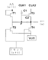
当該図で、PUがプルアップノードであり、PDがプルダウンノードであり、第1の制御信号端子CKと第2の制御信号端子CKBに入力される信号が差動入力であるダブルクロック信号である。 In the figure, PU is a pull-up node, PD is a pull-down node, and a signal input to the first control signal terminal CK and the second control signal terminal CKB is a double clock signal that is a differential input. .
例示された実施例において、プリチャージ回路1は、ゲートが制御端であり、ソースが入力端であり、ドレインが出力端である第1のトランジスタM1を含む。
In the illustrated embodiment, the
リセット回路3は、ゲートが制御端であり、ソースが入力端であり、ドレインが出力端である第2のトランジスタM2を含む。 The reset circuit 3 includes a second transistor M2 having a gate as a control terminal, a source as an input terminal, and a drain as an output terminal.
プルアップ回路2は、ゲートが制御端でありソースが入力端であり、ドレインが出力端である第3のトランジスタM3と、一端が第3のトランジスタM3のゲートに接続され他端が第3のトランジスタM3のドレインに接続されるキャパシタC1とを含む。
The pull-up
さらに、上記のトランジスタ(第1のトランジスタ、第2のトランジスタ、第3のトランジスタ、第4のトランジスタ、第5のトランジスタ、第6のトランジスタ、第7のトランジスタ、第8のトランジスタ)は薄膜トランジスタである。 Further, the above transistors (the first transistor, the second transistor, the third transistor, the fourth transistor, the fifth transistor, the sixth transistor, the seventh transistor, and the eighth transistor) are thin film transistors. .
具体的には、図4に示すように、本発明の実施例1のシフトレジスタは、第1のクロック信号期間で、第1の制御信号端子CKがローレベルを出力し、第2の制御信号端子CKBがハイレベルを出力し、前段のシフトレジスト回路出力N−1_OUTがハイレベルであり、後段のシフトレジスト回路出力N+1_OUTがローレベルである。トランジスタM2、M6、M7、M8がオフされ、トランジスタM1、M4はオンされる。前段のシフトレジスト回路出力N−1_OUTはトランジスタM1を介してトランジスタM3のゲートにプリチャージして、プルアップノードPUの電圧を高くさせる。第2の制御信号端子CKはローレベルであると共に、プルアップノードPUはプルダウンノードPDの電圧がローになれるように、プルダウンノードPDを引き下げ、トランジスタM3のゲートであるプルアップノードPUがプリチャージする(Pre−charging)状態を維持するように、トランジスタM6、M7いずれもオフされ、出力端OUTPUT電圧がローレベルを維持する。 Specifically, as illustrated in FIG. 4, in the shift register according to the first embodiment of the present invention, the first control signal terminal CK outputs a low level during the first clock signal period, and the second control signal The terminal CKB outputs a high level, the preceding shift register circuit output N-1_OUT is at a high level, and the subsequent shift register circuit output N + 1_OUT is at a low level. Transistors M2, M6, M7, and M8 are turned off, and transistors M1 and M4 are turned on. The shift register circuit output N-1_OUT in the previous stage is precharged to the gate of the transistor M3 through the transistor M1, and the voltage of the pull-up node PU is increased. The second control signal terminal CK is at low level, and the pull-up node PU pulls down the pull-down node PD so that the voltage of the pull-down node PD becomes low, and the pull-up node PU that is the gate of the transistor M3 is precharged. The transistors M6 and M7 are both turned off to maintain the pre-charging state, and the output terminal OUTPUT voltage maintains the low level.
第2のクロック信号期間で、回路がプリチャージした(Pre−charging)後、第1の制御信号端子CKの出力がハイレベルであり、第2の制御信号端子CKBの出力がローレベルであり、前段のシフトレジスト回路出力N−1_OUTがローレベルであり、後段のシフトレジスト回路出力N+1_OUTがローレベルである。トランジスタM1、M2、M4がオフされる。キャパシタC1の昇圧(boost)作用によってプルアップノードPUが引き上げされ、トランジスタM3がオンされ、出力端OUTPUTが高電圧信号を出力する。トランジスタM8のソース・ドレインが短絡されてコンデンサに等価し、プルダウンノードPDのレベルを第1の制御信号端子CKの信号の変化に結合させ、その時プルアップノードPUがハイレベルであり、トランジスタM5がオンされ、トランジスタM8、M5の幅・長比がプルダウンノードPDのレベルを低くさせ、トランジスタM7、M8がオフされる。その期間のトランジスタM8の等価コンデンサの容量はトランジスタがオンされる時の等価容量である。プルアップノードPUがハイレベルを維持し、出力端OUTPUTの出力がハイレベルを維持して、前段のシフトレジスト回路出力N−1_OUT信号をシフトする。 In the second clock signal period, after the circuit is pre-charged (Pre-charging), the output of the first control signal terminal CK is high level, the output of the second control signal terminal CKB is low level, The first-stage shift registration circuit output N-1_OUT is at a low level, and the second-stage shift registration circuit output N + 1_OUT is at a low level. Transistors M1, M2, and M4 are turned off. The pull-up node PU is pulled up by the boosting action of the capacitor C1, the transistor M3 is turned on, and the output terminal OUTPUT outputs a high voltage signal. The source and drain of the transistor M8 are short-circuited to be equivalent to a capacitor, and the level of the pull-down node PD is coupled to the change of the signal of the first control signal terminal CK. At that time, the pull-up node PU is at a high level. Turned on, the width / length ratio of the transistors M8 and M5 lowers the level of the pull-down node PD, and the transistors M7 and M8 are turned off. The capacitance of the equivalent capacitor of the transistor M8 during that period is the equivalent capacitance when the transistor is turned on. The pull-up node PU is maintained at a high level, and the output of the output terminal OUTPUT is maintained at a high level, and the shift register circuit output N-1_OUT signal of the previous stage is shifted.
第3のクロック信号期間で、前段のシフトレジスト回路出力N−1_OUTがローレベルであり、第1の制御信号端子CKがローレベルであり、第2の制御信号端子CKBがハイレベルであり、後段のシフトレジスト回路出力N+1_OUTがハイレベルである。トランジスタM1がオフされ、トランジスタM2、M4がオンされる。プルアップノードPUと出力端OUTPUTがローレベルに変化する。 In the third clock signal period, the shift register circuit output N-1_OUT in the previous stage is at the low level, the first control signal terminal CK is at the low level, the second control signal terminal CKB is at the high level, and the subsequent stage The shift registration circuit output N + 1_OUT is at the high level. The transistor M1 is turned off, and the transistors M2 and M4 are turned on. The pull-up node PU and the output terminal OUTPUT change to a low level.
第4のクロック信号期間で、前段のシフトレジスト回路出力N−1_OUTがローレベルであり、後段のシフトレジスト回路出力N+1_OUTがローレベルであり、第1の制御信号端子CKがハイレベルであり、第2の制御信号端子CKBがローレベルである。トランジスタM1、M2、M4がオフされ、プルアップノードPUがローレベルであることによって、トランジスタM3、M5がオフされる。トランジスタM8のソース・ドレインが短絡されてコンデンサに等価し、第1の制御信号端子CKがハイレベルであり、プルダウンノードPDがトランジスタM8を介して第1の制御信号端子CKのハイレベルと結合して、トランジスタM6、M7をオンさせることによって、プルアップノードPUと出力端OUTPUTがローレベルまでプルダウンされる。その期間、トランジスタM8の等価容量はトランジスタがオンされる時の等価容量であり、容量はトランジスタがオフされる時の等価容量より大きい。 In the fourth clock signal period, the first-stage shift registration circuit output N-1_OUT is at the low level, the second-stage shift registration circuit output N + 1_OUT is at the low level, the first control signal terminal CK is at the high level, 2 control signal terminal CKB is at low level. The transistors M1, M2, and M4 are turned off, and the pull-up node PU is at a low level, whereby the transistors M3 and M5 are turned off. The source and drain of the transistor M8 are short-circuited to be equivalent to a capacitor, the first control signal terminal CK is at a high level, and the pull-down node PD is coupled to the high level of the first control signal terminal CK through the transistor M8. Thus, by turning on the transistors M6 and M7, the pull-up node PU and the output terminal OUTPUT are pulled down to the low level. During that period, the equivalent capacitance of the transistor M8 is an equivalent capacitance when the transistor is turned on, and the capacitance is larger than the equivalent capacitance when the transistor is turned off.
第5のクロック信号期間で、前段のシフトレジスト回路出力N−1_OUTがローレベルであり、後段のシフトレジスト回路出力N+1_OUTがローレベルであり、第1の制御信号端子CKがローレベルであり、第2の制御信号端子CKBがハイレベルである。トランジスタM1、M2がオフされ、プルアップノードPUがローレベルであることによって、トランジスタM3、M5がオフされる。トランジスタM4がオンされて、出力端OUTPUTがローレベルまでプルダウンされる。トランジスタM8のソース・ドレインが短絡されてコンデンサに等価し、第1の制御信号端子CKがローレベルであり、プルダウンノードPDがトランジスタM8を介して第1の制御信号端子CKのローレベルと結合し、その期間のトランジスタM8の等価容量の容量はトランジスタがオフされる時の等価容量であり、容量はトランジスタがオンされる時の等価容量より小さい。 In the fifth clock signal period, the shift register circuit output N-1_OUT at the previous stage is at the low level, the shift register circuit output N + 1_OUT at the subsequent stage is at the low level, the first control signal terminal CK is at the low level, 2 control signal terminal CKB is at high level. When the transistors M1 and M2 are turned off and the pull-up node PU is at a low level, the transistors M3 and M5 are turned off. The transistor M4 is turned on, and the output terminal OUTPUT is pulled down to a low level. The source and drain of the transistor M8 are short-circuited to be equivalent to a capacitor, the first control signal terminal CK is low level, and the pull-down node PD is coupled to the low level of the first control signal terminal CK via the transistor M8. The capacity of the equivalent capacity of the transistor M8 during that period is the equivalent capacity when the transistor is turned off, and the capacity is smaller than the equivalent capacity when the transistor is turned on.
図5は本発明の実施例のシフトレジスタ回路のシーケンス図であり、ここで、STVが開始信号であり、GL0〜GLnがn段のシフトレジスト回路の出力端である。 FIG. 5 is a sequence diagram of the shift register circuit according to the embodiment of the present invention, where STV is a start signal and GL0 to GLn are output terminals of the n-stage shift register circuit.
本発明の実施例のシフトレジスタが回路の動作周期を減少し、閾値電圧のドリフト問題を改善し、ソース・ドレインが短絡されたトランジスタで、制御信号のプルダウンノードに対する制御を実現して、プルダウンノードを第1の制御信号がハイレベルである時急速に上昇させ、第1の制御信号がローレベルである時プルダウンの幅が減少して、制御信号による回路に対する制御をさらによく実現できる。 The shift register according to the embodiment of the present invention reduces the operation period of the circuit, improves the threshold voltage drift problem, and realizes control of the pull-down node of the control signal by using a transistor whose source and drain are short-circuited. When the first control signal is at a high level, the voltage is rapidly increased, and when the first control signal is at a low level, the pull-down width is decreased, so that the control of the circuit by the control signal can be realized better.
実施例2
本発明の実施例のシフトレジスタは図6に示すようであり、その特徴が実施例1と基本的に同じであって、実施例1との違い点は、第1のホールド回路4Aが、ゲートがプルアップ回路の制御端に接続され、ドレインが接地された第5のトランジスタM5と、制御端が前記ホールド回路の第1の制御端であり、ソースとドレインが第5のトランジスタM5のソースに接続される第8のトランジスタM8とを含み、
第2のホールド回路4Bは、ゲートが前記ホールド回路の第2の制御端であり、ソースが第7のトランジスタM7のソース及びプルアップ回路2の出力端に接続され、ドレインが接地される第4のトランジスタM4と、ゲートが第7のトランジスタM7のゲートと接続され、ソースがプリチャージ回路1の出力端とリセット回路3の入力端とプルアップ回路2の制御端とに接続され、ドレインが第7のトランジスタM7のソースに接続される第6のトランジスタM6と、ドレインが接地される第7のトランジスタM7とを含み、
第1のホールド回路4Aと第2のホールド回路4BはプルダウンノードPDによって接続され、プルダウンノードPDは、第8のトランジスタのソースとドレイン、第5のトランジスタのソース、第6のトランジスタのゲート、第7のトランジスタのゲートに接続されることである。
Example 2
The shift register of the embodiment of the present invention is as shown in FIG. 6, and its features are basically the same as those of the first embodiment. The difference from the first embodiment is that the first hold circuit 4A has a gate. Is connected to the control terminal of the pull-up circuit, the drain is grounded, the control terminal is the first control terminal of the hold circuit, and the source and drain are connected to the source of the fifth transistor M5. An eighth transistor M8 connected,
In the second hold circuit 4B, the gate is the second control terminal of the hold circuit, the source is connected to the source of the seventh transistor M7 and the output terminal of the pull-up
The first hold circuit 4A and the second hold circuit 4B are connected by a pull-down node PD. The pull-down node PD includes the source and drain of the eighth transistor, the source of the fifth transistor, the gate of the sixth transistor, 7 to be connected to the gate of the transistor.
ソース・ドレインが短絡されたトランジスタで容量結合の効果を実現して、本発明の実施例の方案はいろいろあることができる。例えば、プリチャージ回路Pre−chargingとリセット回路Resetモジュールの設計でGOA両方向走査を実現し、設計することでプルアップノードPUと出力端OUTPUTを前段または後段のシフトレジスタの出力までプルダウンし、或いは本発明の技術の四つのクロック回路を採用し、本発明のソース・ドレインが短絡されたトランジスタで容量結合の効果を実現する技術方案を使用すれば、いずれも本発明の保護の範囲に入る。 Various embodiments of the present invention can be realized by realizing a capacitive coupling effect with a transistor whose source and drain are short-circuited. For example, GOA bi-directional scanning is realized by designing the precharge circuit Pre-charging and the reset circuit Reset module, and by pulling down the pull-up node PU and the output terminal OUTPUT to the output of the preceding or succeeding shift register, Any of the four clock circuits of the technology of the invention and the use of the technical scheme for realizing the capacitive coupling effect with the transistor having the source and drain short-circuited according to the present invention will fall within the protection scope of the present invention.
本発明の実施例のゲート駆動回路は前記シフトレジスタを含む。 A gate driving circuit according to an embodiment of the present invention includes the shift register.
本発明の実施例の表示装置は前記ゲート駆動回路を含む。 A display device according to an embodiment of the present invention includes the gate driving circuit.
図7は本発明の例示的な実施例のゲート駆動方法のフローチャートを示す。図7に示すように、該方法の操作プロセスは、以下のようである。
ステップS1で、プリチャージ回路がプルアップ回路に充電し、
ステップS2で、プルアップ回路がシフトレジスト回路のレベルをプルアップさせ、シフトレジスト回路がハイレベルを出力し、
ステップS3で、リセット回路がシフトレジスト回路をリセットさせ、
ステップS4で、シフトレジスタ回路がリセットされた後、ホールド回路はシフトレジスト回路の出力レベルをホールドする。
FIG. 7 shows a flowchart of a gate driving method according to an exemplary embodiment of the present invention. As shown in FIG. 7, the operation process of the method is as follows.
In step S1, the precharge circuit charges the pull-up circuit,
In step S2, the pull-up circuit pulls up the level of the shift resist circuit, the shift resist circuit outputs a high level,
In step S3, the reset circuit resets the shift registration circuit,
In step S4, after the shift register circuit is reset, the hold circuit holds the output level of the shift registration circuit.
ステップS4で、ホールド回路における第8のトランジスタの等価容量は第8のトランジスタのオン又はオフによって変化し、第8のトランジスタがオンされる場合の等価容量は第8のトランジスタがオフされる場合の等価容量より大きい。 In step S4, the equivalent capacitance of the eighth transistor in the hold circuit changes depending on whether the eighth transistor is turned on or off, and the equivalent capacitance when the eighth transistor is turned on is the same as when the eighth transistor is turned off. Greater than equivalent capacity.
以上の実施形態は本発明を説明するためにのみ用いられ、本発明を限定するためのものではなく、当業者については、本発明の精神及び趣旨から逸脱しない場合、様々な変化及び変形をすることができる。従って、等価の技術案はいずれも本発明の範囲に入り、本発明の特許保護範囲は請求の範囲に限定される。 The above embodiments are used only to explain the present invention, not to limit the present invention. For those skilled in the art, various changes and modifications can be made without departing from the spirit and the spirit of the present invention. be able to. Accordingly, any equivalent technical solution falls within the scope of the present invention, and the patent protection scope of the present invention is limited to the scope of the claims.
M1 第1のトランジスタ
M2 第2のトランジスタ
M3 第3のトランジスタ
M4 第4のトランジスタ
M5 第5のトランジスタ
M6 第6のトランジスタ
M7 第7のトランジスタ
M8 第8のトランジスタ
PD プルダウンノード
PU プルアップノード
Reset リセット回路
RST リセット信号
STV 開始信号
M1 1st transistor M2 2nd transistor M3 3rd transistor M4 4th transistor M5 5th transistor M6 6th transistor M7 7th transistor M8 8th transistor PD Pull-down node PU Pull-up node Reset Reset circuit RST Reset signal STV Start signal
Claims (9)
プルアップ回路にプリチャージするためのプリチャージ回路と、
プリチャージされた後、出力端にハイレベルを出力させるプルアップ回路と、
出力端がハイレベルを出力した後、前記第N段のシフトレジスト回路をリセットするリセット回路と、
前記第N段のシフトレジスト回路がリセットされた後、第N段のシフトレジスト回路の出力レベルをホールドするホールド回路と
を含み、
前記プリチャージ回路は、制御端と入力端が前段のシフトレジスト回路の出力端に接続され、出力端が前記リセット回路の入力端に接続され、
前記プルアップ回路は、入力端が第1の制御信号端子に接続され、
前記リセット回路は、制御端が後段のシフトレジスト回路の出力端に接続され、出力端が接地され、
前記ホールド回路は、前記プリチャージ回路の出力端と、前記リセット回路の入力端と、プルアップ回路の制御端と、プルアップ回路の出力端とに接続され、第1の制御端が前記第1の制御信号端子に接続され、第2の制御端が第2の制御信号端子に接続され、
前記ホールド回路は、第1のホールド回路と、第2のホールド回路とを含み、
前記第1のホールド回路は、ゲートが前記プルアップ回路の制御端に接続され、ドレインが接地される第5のトランジスタと、ゲートが前記ホールド回路の第1の制御端であり、ソースとドレインが前記第5のトランジスタのソース及びプルダウンノードに接続される第8のトランジスタと、を含み、
前記第1のホールド回路と第2のホールド回路は、前記プルダウンノードによって接続され、
前記第5のトランジスタと前記第8のトランジスタのいずれもオンされる場合、前記第5のトランジスタと前記第8のトランジスタの幅・長比によって前記プルダウンノードを低くさせるシフトレジスタ。 The shift register includes a plurality of stages of shift registration circuits, and the N-th stage shift registration circuit of the plurality of stages of shift registration circuits includes:
A precharge circuit for precharging the pull-up circuit;
A pull-up circuit that outputs a high level to the output terminal after being precharged;
A reset circuit for resetting the N-th shift resist circuit after the output terminal outputs a high level;
A hold circuit for holding an output level of the N-th shift resist circuit after the N-th shift resist circuit is reset,
In the precharge circuit, a control terminal and an input terminal are connected to an output terminal of a previous shift resist circuit, and an output terminal is connected to an input terminal of the reset circuit.
The pull-up circuit has an input terminal connected to the first control signal terminal,
In the reset circuit, the control end is connected to the output end of the subsequent shift register circuit, the output end is grounded,
The hold circuit is connected to an output terminal of the precharge circuit, an input terminal of the reset circuit, a control terminal of the pull-up circuit, and an output terminal of the pull-up circuit, and a first control terminal is connected to the first control terminal. The second control terminal is connected to the second control signal terminal,
The hold circuit includes a first hold circuit and a second hold circuit,
The first hold circuit includes a fifth transistor whose gate is connected to the control end of the pull-up circuit and whose drain is grounded, the gate is the first control end of the hold circuit, and the source and drain are An eighth transistor connected to the source of the fifth transistor and a pull-down node;
The first hold circuit and the second hold circuit are connected by the pull-down node,
A shift register that lowers the pull-down node according to a width / length ratio of the fifth transistor and the eighth transistor when both the fifth transistor and the eighth transistor are turned on.
前記プルダウンノードは、さらに前記第6のトランジスタのゲート、前記第7のトランジスタのゲートに接続される請求項1に記載のシフトレジスタ。 The second hold circuit includes a fourth transistor whose gate is the second control terminal of the hold circuit, whose source is connected to the source of the sixth transistor and the output terminal of the pull-up circuit, and whose drain is grounded. A sixth transistor whose gate is connected to the gate of the seventh transistor and whose drain is grounded, and whose source is the output terminal of the precharge circuit, the input terminal of the reset circuit, and the control terminal of the pull-up circuit The seventh transistor having a drain connected to ground, and
2. The shift register according to claim 1, wherein the pull-down node is further connected to a gate of the sixth transistor and a gate of the seventh transistor.
前記プルダウンノードは、さらに前記第6のトランジスタのゲート、前記第7のトランジスタのゲートに接続される請求項1に記載のシフトレジスタ。 In the second hold circuit, a gate is a second control terminal of the hold circuit, a source is connected to a source of the seventh transistor and an output terminal of the pull-up circuit, and a drain is grounded. The transistor has a gate connected to the gate of the seventh transistor, a source connected to an output terminal of the precharge circuit, an input terminal of the reset circuit, and a control terminal of the pull-up circuit, and a drain connected to the seventh transistor. A sixth transistor connected to the source of the transistor, and the seventh transistor having a drain grounded,
2. The shift register according to claim 1, wherein the pull-down node is further connected to a gate of the sixth transistor and a gate of the seventh transistor.
請求項1〜6のいずれかに記載のシフトレジスタを含むゲート駆動回路。 A gate drive circuit,
A gate drive circuit including the shift register according to claim 1.
請求項7に記載のゲート駆動回路を含む表示装置。 A display device,
A display device comprising the gate drive circuit according to claim 7.
プリチャージ回路がプルアップ回路に充電し(S1)、
プルアップ回路がシフトレジスト回路のレベルをプルアップさせ、シフトレジスト回路がハイレベルを出力し(S2)、
リセット回路がシフトレジスト回路をリセットさせ(S3)、
シフトレジスト回路がリセットされた後、ホールド回路がシフトレジスト回路の出力レベルをホールドし(S4)、
前記ステップS4で、ホールド回路における第8のトランジスタの等価容量は前記第8のトランジスタのオン又はオフによって変化し、前記第8のトランジスタがオンされる場合の等価容量は前記第8のトランジスタがオフされる場合の等価容量より大きいゲート駆動方法。 A gate driving method using a shift register according to claim 1, comprising the following steps:
The precharge circuit charges the pull-up circuit (S1),
The pull-up circuit pulls up the level of the shift resist circuit, and the shift resist circuit outputs a high level (S2).
The reset circuit resets the shift registration circuit (S3),
After the shift registration circuit is reset, the hold circuit holds the output level of the shift registration circuit (S4),
In step S4, the equivalent capacitance of the eighth transistor in the hold circuit changes depending on whether the eighth transistor is on or off, and the equivalent capacitance when the eighth transistor is turned on is that the eighth transistor is off. If the gate drive method is larger than the equivalent capacity.
Applications Claiming Priority (3)
| Application Number | Priority Date | Filing Date | Title |
|---|---|---|---|
| CN201310082062.7A CN103208263B (en) | 2013-03-14 | 2013-03-14 | Shift register, display device, gate drive circuit and driving method |
| CN201310082062.7 | 2013-03-14 | ||
| PCT/CN2013/078443 WO2014139249A1 (en) | 2013-03-14 | 2013-06-28 | Shift register, display device, gate drive circuit and driving method |
Publications (3)
| Publication Number | Publication Date |
|---|---|
| JP2016517607A JP2016517607A (en) | 2016-06-16 |
| JP2016517607A5 JP2016517607A5 (en) | 2016-08-12 |
| JP6328153B2 true JP6328153B2 (en) | 2018-05-23 |
Family
ID=48755473
Family Applications (1)
| Application Number | Title | Priority Date | Filing Date |
|---|---|---|---|
| JP2015561904A Expired - Fee Related JP6328153B2 (en) | 2013-03-14 | 2013-06-28 | Shift register, display device, gate drive circuit, and drive method |
Country Status (6)
| Country | Link |
|---|---|
| US (1) | US9240781B2 (en) |
| EP (1) | EP2975604B1 (en) |
| JP (1) | JP6328153B2 (en) |
| KR (1) | KR101580422B1 (en) |
| CN (1) | CN103208263B (en) |
| WO (1) | WO2014139249A1 (en) |
Families Citing this family (28)
| Publication number | Priority date | Publication date | Assignee | Title |
|---|---|---|---|---|
| TWI514365B (en) * | 2014-04-10 | 2015-12-21 | Au Optronics Corp | Gate driving circuit and shift register |
| TWI517134B (en) * | 2014-05-06 | 2016-01-11 | 友達光電股份有限公司 | Scan circuit and shift register |
| CN106688029A (en) * | 2014-05-28 | 2017-05-17 | 可隆奥托株式会社 | Shift circuit, shift resistor, and display device |
| CN104537970B (en) * | 2014-11-27 | 2017-03-15 | 上海天马微电子有限公司 | Drive element of the grid, gate driver circuit and driving method, display device |
| CN104575429A (en) * | 2015-01-30 | 2015-04-29 | 合肥京东方光电科技有限公司 | Shifting register unit, drive method thereof, gate drive circuit and display device |
| CN104835442B (en) | 2015-05-28 | 2017-09-26 | 京东方科技集团股份有限公司 | Shift register and its driving method, gate driving circuit and display device |
| CN105741740B (en) * | 2016-04-27 | 2019-11-08 | 京东方科技集团股份有限公司 | GOA unit and its driving method, GOA circuit, display device |
| CN106023914A (en) * | 2016-05-16 | 2016-10-12 | 京东方科技集团股份有限公司 | Shift register and operation method thereof |
| KR101882435B1 (en) | 2016-10-05 | 2018-08-24 | 실리콘 디스플레이 (주) | Shift register |
| KR102490159B1 (en) * | 2016-10-31 | 2023-01-20 | 엘지디스플레이 주식회사 | Gate driving circuit and display device having in-cell touch sensor using the same |
| CN106548740A (en) * | 2016-12-02 | 2017-03-29 | 京东方科技集团股份有限公司 | Shift register circuit and its driving method, gate driver circuit and display device |
| CN106409211B (en) * | 2016-12-12 | 2019-06-07 | 上海天马微电子有限公司 | A kind of gate driving circuit, array substrate and display device |
| CN108630155B (en) * | 2017-03-24 | 2019-12-31 | 合肥鑫晟光电科技有限公司 | Reset circuit, shift register unit, gate drive circuit, display device and drive method |
| CN108665860B (en) * | 2017-03-30 | 2019-11-08 | 京东方科技集团股份有限公司 | A kind of GOA unit and its driving method, GOA driving circuit, display device |
| TWI606435B (en) * | 2017-04-06 | 2017-11-21 | 敦泰電子股份有限公司 | Gate line drive circuit and display device having the same |
| TWI625710B (en) * | 2017-04-28 | 2018-06-01 | 友達光電股份有限公司 | Gate driving circuit and display device using the same |
| CN106920526B (en) * | 2017-05-04 | 2020-02-14 | 合肥鑫晟光电科技有限公司 | Shift register and driving method thereof and grid driving circuit |
| CN107123403B (en) * | 2017-05-27 | 2018-08-28 | 惠科股份有限公司 | Shift scratch circuit and its display panel of application |
| CN107248401B (en) * | 2017-08-08 | 2020-04-03 | 京东方科技集团股份有限公司 | GOA circuit, driving method thereof and display device |
| CN109859698A (en) * | 2018-08-21 | 2019-06-07 | 信利半导体有限公司 | A kind of GOA driving circuit |
| EP3882901A4 (en) * | 2018-11-14 | 2022-06-29 | BOE Technology Group Co., Ltd. | Shift register unit, drive method, gate drive circuit, and display device |
| TWI684974B (en) * | 2018-12-27 | 2020-02-11 | 友達光電股份有限公司 | Display apparatus |
| CN109584832B (en) * | 2019-01-18 | 2020-10-27 | 重庆京东方光电科技有限公司 | Shifting register and driving method thereof, grid driving circuit and display device |
| CN110111831B (en) * | 2019-04-24 | 2021-08-06 | 厦门天马微电子有限公司 | Shift register, grid drive circuit and display device |
| CN111951715B (en) * | 2019-04-30 | 2024-03-29 | 上海和辉光电股份有限公司 | Pixel circuit, driving method and display |
| CN111627404B (en) * | 2020-06-09 | 2021-11-23 | 武汉华星光电技术有限公司 | GOA circuit, display panel and display device |
| CN111754938B (en) | 2020-07-24 | 2023-11-28 | 武汉华星光电半导体显示技术有限公司 | Pixel circuit, driving method thereof and display device |
| CN114187879B (en) * | 2021-12-31 | 2023-04-25 | 长沙惠科光电有限公司 | Driving circuit of display panel, array substrate and display panel |
Family Cites Families (24)
| Publication number | Priority date | Publication date | Assignee | Title |
|---|---|---|---|---|
| TWI229442B (en) * | 2002-10-25 | 2005-03-11 | Au Optronics Corp | Capacitor in a pixel structure |
| US7319452B2 (en) | 2003-03-25 | 2008-01-15 | Samsung Electronics Co., Ltd. | Shift register and display device having the same |
| KR100970269B1 (en) * | 2003-10-20 | 2010-07-16 | 삼성전자주식회사 | Shift register, and scan drive circuit and display device having the same |
| US7486269B2 (en) | 2003-07-09 | 2009-02-03 | Samsung Electronics Co., Ltd. | Shift register, scan driving circuit and display apparatus having the same |
| US8605027B2 (en) * | 2004-06-30 | 2013-12-10 | Samsung Display Co., Ltd. | Shift register, display device having the same and method of driving the same |
| US7868320B2 (en) * | 2005-05-31 | 2011-01-11 | Semiconductor Energy Laboratory Co., Ltd. | Semiconductor device and manufacturing method thereof |
| KR101143004B1 (en) * | 2005-06-13 | 2012-05-11 | 삼성전자주식회사 | Shift register and display device including shifter register |
| CN1899202A (en) | 2005-11-08 | 2007-01-24 | 乐金电子(天津)电器有限公司 | Automatic water discharge preventing structure for dish washing machine |
| JP2007242129A (en) * | 2006-03-08 | 2007-09-20 | Mitsubishi Electric Corp | Shift register circuit and image display device having the circuit |
| JP5079350B2 (en) * | 2006-04-25 | 2012-11-21 | 三菱電機株式会社 | Shift register circuit |
| KR101300038B1 (en) * | 2006-08-08 | 2013-08-29 | 삼성디스플레이 주식회사 | Gate driving circuit and display apparatus having the same |
| KR101240655B1 (en) * | 2006-09-29 | 2013-03-08 | 삼성디스플레이 주식회사 | Driving apparatus for display device |
| KR101393635B1 (en) * | 2007-06-04 | 2014-05-09 | 삼성디스플레이 주식회사 | Driving apparatus for display device and display device including the same |
| KR101471553B1 (en) * | 2008-08-14 | 2014-12-10 | 삼성디스플레이 주식회사 | Gate driving circuit and display device having the same |
| KR101536218B1 (en) * | 2008-12-26 | 2015-07-13 | 삼성디스플레이 주식회사 | Gate driving circuit, display device having the same and method for manufacturing the gate driving circuit |
| KR101520807B1 (en) * | 2009-01-05 | 2015-05-18 | 삼성디스플레이 주식회사 | Gate drive circuit and display apparatus having the same |
| KR101022092B1 (en) * | 2009-01-12 | 2011-03-17 | 삼성모바일디스플레이주식회사 | Shift Register and Organic Light Emitting Display Device Using the Same |
| KR101543281B1 (en) | 2009-02-19 | 2015-08-11 | 삼성디스플레이 주식회사 | Gate driving circuit and display device having the gate driving circuit |
| JP5253275B2 (en) * | 2009-04-03 | 2013-07-31 | セミコンダクター・コンポーネンツ・インダストリーズ・リミテッド・ライアビリティ・カンパニー | Amplifier circuit for condenser microphone |
| CN101625841A (en) * | 2009-07-29 | 2010-01-13 | 友达光电股份有限公司 | Liquid crystal display and shift registering device |
| KR101752834B1 (en) | 2009-12-29 | 2017-07-03 | 삼성디스플레이 주식회사 | Gate driving circuit and display apparatus having the same |
| CN102467891B (en) * | 2010-10-29 | 2013-10-09 | 京东方科技集团股份有限公司 | Shift register unit, gate driving device and liquid crystal display |
| CN102930812B (en) * | 2012-10-09 | 2015-08-19 | 北京京东方光电科技有限公司 | Shift register, grid line integrated drive electronics, array base palte and display |
| CN102945650B (en) * | 2012-10-30 | 2015-04-22 | 合肥京东方光电科技有限公司 | Shift register and array substrate grid driving device |
-
2013
- 2013-03-14 CN CN201310082062.7A patent/CN103208263B/en not_active Expired - Fee Related
- 2013-06-28 EP EP13854214.7A patent/EP2975604B1/en active Active
- 2013-06-28 JP JP2015561904A patent/JP6328153B2/en not_active Expired - Fee Related
- 2013-06-28 WO PCT/CN2013/078443 patent/WO2014139249A1/en active Application Filing
- 2013-06-28 KR KR1020147017047A patent/KR101580422B1/en active IP Right Grant
- 2013-06-28 US US14/360,879 patent/US9240781B2/en not_active Expired - Fee Related
Also Published As
| Publication number | Publication date |
|---|---|
| EP2975604A1 (en) | 2016-01-20 |
| US20150280704A1 (en) | 2015-10-01 |
| WO2014139249A1 (en) | 2014-09-18 |
| CN103208263B (en) | 2015-03-04 |
| KR20140122221A (en) | 2014-10-17 |
| EP2975604A4 (en) | 2016-12-21 |
| EP2975604B1 (en) | 2020-03-25 |
| KR101580422B1 (en) | 2015-12-23 |
| JP2016517607A (en) | 2016-06-16 |
| CN103208263A (en) | 2013-07-17 |
| US9240781B2 (en) | 2016-01-19 |
Similar Documents
| Publication | Publication Date | Title |
|---|---|---|
| JP6328153B2 (en) | Shift register, display device, gate drive circuit, and drive method | |
| US9734918B2 (en) | Shift register and the driving method thereof, gate driving apparatus and display apparatus | |
| US10593286B2 (en) | Shift register, gate driving circuit, display panel and driving method | |
| US9558843B2 (en) | Shift register unit, gate driving circuit, and display device comprising the same | |
| CN102708779B (en) | Shift register and driving device thereof, grid driving device and display device | |
| US10283030B2 (en) | Shift register, gate driver, display panel and driving method | |
| WO2016070543A1 (en) | Shift register unit, gate driving circuit and display device | |
| WO2017054399A1 (en) | Shift register, drive method therefor, gate drive circuit and display apparatus | |
| JP4876108B2 (en) | Method for reducing bootstrap point voltage of electronic circuit and apparatus using the method | |
| WO2017067300A1 (en) | Gate driving circuit, driving method therefor, and display panel | |
| US20140126684A1 (en) | Shift register, gate driving circuit and display apparatus | |
| WO2013131425A1 (en) | Shifting register, gate driver and display device | |
| WO2015090019A1 (en) | Shift register unit, gate drive circuit and display device | |
| WO2015010364A1 (en) | Shift register unit, gate drive circuit and display device | |
| WO2013135061A1 (en) | Gate drive circuit and display | |
| JP2011060411A (en) | Shift register unit and gate driving device for liquid crystal display | |
| KR20100083370A (en) | Gate driving circuit and display device having the same | |
| KR20120046062A (en) | Shift register unit, gate driving device and liquid crystal display | |
| US10490156B2 (en) | Shift register, gate driving circuit and display panel | |
| US8836633B2 (en) | Display driving circuit and display panel using the same | |
| US20170103722A1 (en) | Shift register unit, gate driving circuit and display apparatus | |
| WO2019223331A1 (en) | Shift register unit, driving method, gate driving circuit, and display device | |
| CN109712550B (en) | Grid driving circuit and area scanning method | |
| CN110910853B (en) | Shifting register, driving method thereof and grid driving circuit | |
| CN113641266A (en) | Touch display panel and touch display device |
Legal Events
| Date | Code | Title | Description |
|---|---|---|---|
| A521 | Request for written amendment filed |
Free format text: JAPANESE INTERMEDIATE CODE: A523 Effective date: 20160624 |
|
| A621 | Written request for application examination |
Free format text: JAPANESE INTERMEDIATE CODE: A621 Effective date: 20160624 |
|
| A977 | Report on retrieval |
Free format text: JAPANESE INTERMEDIATE CODE: A971007 Effective date: 20170224 |
|
| A131 | Notification of reasons for refusal |
Free format text: JAPANESE INTERMEDIATE CODE: A131 Effective date: 20170306 |
|
| A521 | Request for written amendment filed |
Free format text: JAPANESE INTERMEDIATE CODE: A523 Effective date: 20170606 |
|
| A02 | Decision of refusal |
Free format text: JAPANESE INTERMEDIATE CODE: A02 Effective date: 20170828 |
|
| A521 | Request for written amendment filed |
Free format text: JAPANESE INTERMEDIATE CODE: A523 Effective date: 20171228 |
|
| A911 | Transfer to examiner for re-examination before appeal (zenchi) |
Free format text: JAPANESE INTERMEDIATE CODE: A911 Effective date: 20180115 |
|
| A131 | Notification of reasons for refusal |
Free format text: JAPANESE INTERMEDIATE CODE: A131 Effective date: 20180209 |
|
| A521 | Request for written amendment filed |
Free format text: JAPANESE INTERMEDIATE CODE: A523 Effective date: 20180222 |
|
| TRDD | Decision of grant or rejection written | ||
| A01 | Written decision to grant a patent or to grant a registration (utility model) |
Free format text: JAPANESE INTERMEDIATE CODE: A01 Effective date: 20180319 |
|
| A61 | First payment of annual fees (during grant procedure) |
Free format text: JAPANESE INTERMEDIATE CODE: A61 Effective date: 20180417 |
|
| R150 | Certificate of patent or registration of utility model |
Ref document number: 6328153 Country of ref document: JP Free format text: JAPANESE INTERMEDIATE CODE: R150 |
|
| R250 | Receipt of annual fees |
Free format text: JAPANESE INTERMEDIATE CODE: R250 |
|
| LAPS | Cancellation because of no payment of annual fees |