JP6288317B2 - 無線通信デバイスおよびそれを備えた物品 - Google Patents
無線通信デバイスおよびそれを備えた物品 Download PDFInfo
- Publication number
- JP6288317B2 JP6288317B2 JP2016575711A JP2016575711A JP6288317B2 JP 6288317 B2 JP6288317 B2 JP 6288317B2 JP 2016575711 A JP2016575711 A JP 2016575711A JP 2016575711 A JP2016575711 A JP 2016575711A JP 6288317 B2 JP6288317 B2 JP 6288317B2
- Authority
- JP
- Japan
- Prior art keywords
- electrode
- wireless communication
- radiation electrode
- communication device
- radiation
- Prior art date
- Legal status (The legal status is an assumption and is not a legal conclusion. Google has not performed a legal analysis and makes no representation as to the accuracy of the status listed.)
- Active
Links
Images


Classifications
-
- G—PHYSICS
- G06—COMPUTING OR CALCULATING; COUNTING
- G06K—GRAPHICAL DATA READING; PRESENTATION OF DATA; RECORD CARRIERS; HANDLING RECORD CARRIERS
- G06K19/00—Record carriers for use with machines and with at least a part designed to carry digital markings
- G06K19/06—Record carriers for use with machines and with at least a part designed to carry digital markings characterised by the kind of the digital marking, e.g. shape, nature, code
- G06K19/067—Record carriers with conductive marks, printed circuits or semiconductor circuit elements, e.g. credit or identity cards also with resonating or responding marks without active components
- G06K19/07—Record carriers with conductive marks, printed circuits or semiconductor circuit elements, e.g. credit or identity cards also with resonating or responding marks without active components with integrated circuit chips
- G06K19/077—Constructional details, e.g. mounting of circuits in the carrier
- G06K19/07749—Constructional details, e.g. mounting of circuits in the carrier the record carrier being capable of non-contact communication, e.g. constructional details of the antenna of a non-contact smart card
- G06K19/07771—Constructional details, e.g. mounting of circuits in the carrier the record carrier being capable of non-contact communication, e.g. constructional details of the antenna of a non-contact smart card the record carrier comprising means for minimising adverse effects on the data communication capability of the record carrier, e.g. minimising Eddy currents induced in a proximate metal or otherwise electromagnetically interfering object
-
- H—ELECTRICITY
- H01—ELECTRIC ELEMENTS
- H01Q—ANTENNAS, i.e. RADIO AERIALS
- H01Q1/00—Details of, or arrangements associated with, antennas
- H01Q1/12—Supports; Mounting means
- H01Q1/22—Supports; Mounting means by structural association with other equipment or articles
- H01Q1/2208—Supports; Mounting means by structural association with other equipment or articles associated with components used in interrogation type services, i.e. in systems for information exchange between an interrogator/reader and a tag/transponder, e.g. in Radio Frequency Identification [RFID] systems
- H01Q1/2216—Supports; Mounting means by structural association with other equipment or articles associated with components used in interrogation type services, i.e. in systems for information exchange between an interrogator/reader and a tag/transponder, e.g. in Radio Frequency Identification [RFID] systems used in interrogator/reader equipment
-
- H—ELECTRICITY
- H01—ELECTRIC ELEMENTS
- H01Q—ANTENNAS, i.e. RADIO AERIALS
- H01Q1/00—Details of, or arrangements associated with, antennas
- H01Q1/12—Supports; Mounting means
- H01Q1/22—Supports; Mounting means by structural association with other equipment or articles
- H01Q1/2208—Supports; Mounting means by structural association with other equipment or articles associated with components used in interrogation type services, i.e. in systems for information exchange between an interrogator/reader and a tag/transponder, e.g. in Radio Frequency Identification [RFID] systems
- H01Q1/2225—Supports; Mounting means by structural association with other equipment or articles associated with components used in interrogation type services, i.e. in systems for information exchange between an interrogator/reader and a tag/transponder, e.g. in Radio Frequency Identification [RFID] systems used in active tags, i.e. provided with its own power source or in passive tags, i.e. deriving power from RF signal
-
- H—ELECTRICITY
- H01—ELECTRIC ELEMENTS
- H01Q—ANTENNAS, i.e. RADIO AERIALS
- H01Q1/00—Details of, or arrangements associated with, antennas
- H01Q1/36—Structural form of radiating elements, e.g. cone, spiral, umbrella; Particular materials used therewith
- H01Q1/38—Structural form of radiating elements, e.g. cone, spiral, umbrella; Particular materials used therewith formed by a conductive layer on an insulating support
-
- H—ELECTRICITY
- H01—ELECTRIC ELEMENTS
- H01Q—ANTENNAS, i.e. RADIO AERIALS
- H01Q1/00—Details of, or arrangements associated with, antennas
- H01Q1/48—Earthing means; Earth screens; Counterpoises
-
- H—ELECTRICITY
- H01—ELECTRIC ELEMENTS
- H01Q—ANTENNAS, i.e. RADIO AERIALS
- H01Q19/00—Combinations of primary active antenna elements and units with secondary devices, e.g. with quasi-optical devices, for giving the antenna a desired directional characteristic
- H01Q19/005—Patch antenna using one or more coplanar parasitic elements
-
- H—ELECTRICITY
- H01—ELECTRIC ELEMENTS
- H01Q—ANTENNAS, i.e. RADIO AERIALS
- H01Q19/00—Combinations of primary active antenna elements and units with secondary devices, e.g. with quasi-optical devices, for giving the antenna a desired directional characteristic
- H01Q19/22—Combinations of primary active antenna elements and units with secondary devices, e.g. with quasi-optical devices, for giving the antenna a desired directional characteristic using a secondary device in the form of a single substantially straight conductive element
- H01Q19/26—Combinations of primary active antenna elements and units with secondary devices, e.g. with quasi-optical devices, for giving the antenna a desired directional characteristic using a secondary device in the form of a single substantially straight conductive element the primary active element being end-fed and elongated
-
- H—ELECTRICITY
- H01—ELECTRIC ELEMENTS
- H01Q—ANTENNAS, i.e. RADIO AERIALS
- H01Q9/00—Electrically-short antennas having dimensions not more than twice the operating wavelength and consisting of conductive active radiating elements
- H01Q9/04—Resonant antennas
- H01Q9/16—Resonant antennas with feed intermediate between the extremities of the antenna, e.g. centre-fed dipole
- H01Q9/26—Resonant antennas with feed intermediate between the extremities of the antenna, e.g. centre-fed dipole with folded element or elements, the folded parts being spaced apart a small fraction of operating wavelength
-
- H—ELECTRICITY
- H01—ELECTRIC ELEMENTS
- H01Q—ANTENNAS, i.e. RADIO AERIALS
- H01Q9/00—Electrically-short antennas having dimensions not more than twice the operating wavelength and consisting of conductive active radiating elements
- H01Q9/04—Resonant antennas
- H01Q9/30—Resonant antennas with feed to end of elongated active element, e.g. unipole
- H01Q9/42—Resonant antennas with feed to end of elongated active element, e.g. unipole with folded element, the folded parts being spaced apart a small fraction of the operating wavelength
-
- G—PHYSICS
- G06—COMPUTING OR CALCULATING; COUNTING
- G06K—GRAPHICAL DATA READING; PRESENTATION OF DATA; RECORD CARRIERS; HANDLING RECORD CARRIERS
- G06K19/00—Record carriers for use with machines and with at least a part designed to carry digital markings
- G06K19/06—Record carriers for use with machines and with at least a part designed to carry digital markings characterised by the kind of the digital marking, e.g. shape, nature, code
- G06K19/067—Record carriers with conductive marks, printed circuits or semiconductor circuit elements, e.g. credit or identity cards also with resonating or responding marks without active components
- G06K19/07—Record carriers with conductive marks, printed circuits or semiconductor circuit elements, e.g. credit or identity cards also with resonating or responding marks without active components with integrated circuit chips
- G06K19/077—Constructional details, e.g. mounting of circuits in the carrier
- G06K19/0772—Physical layout of the record carrier
Landscapes
- Engineering & Computer Science (AREA)
- Physics & Mathematics (AREA)
- Computer Hardware Design (AREA)
- Microelectronics & Electronic Packaging (AREA)
- General Physics & Mathematics (AREA)
- Theoretical Computer Science (AREA)
- Electromagnetism (AREA)
- Details Of Aerials (AREA)
- Support Of Aerials (AREA)
Description
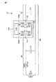
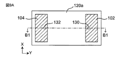
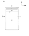
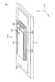
第1および第2の端子電極を備えるRFIC素子と、
前記RFIC素子の前記第1の端子電極に接続されている第1の放射電極と、
前記第1の放射電極に対して独立した状態で、前記第1の放射電極と同層に設けられ、前記RFIC素子の前記第2の端子電極に接続されている第2の放射電極と、
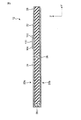
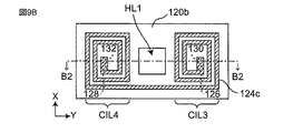
前記第2の放射電極に対して距離をあけて対向するように設けられ、前記第2の放射電極に接続されている裏面電極と、を有し、
前記第1の放射電極に対向する前記裏面電極の部分の面積が、前記第2の放射電極に対向する前記裏面電極の部分の面積に比べて小さい、無線通信デバイスが提供される。
少なくとも一部に金属面を備え、前記金属面に取り付けられた無線通信デバイスを有する物品であって、
前記無線通信デバイスが、
第1および第2の端子電極を備えるRFIC素子と、
前記RFIC素子の前記第1の端子電極に接続されている第1の放射電極と、
前記第1の放射電極に対して独立した状態で、前記第1の放射電極と同層に設けられ、前記RFIC素子の前記第2の端子電極に接続されている第2の放射電極と、
前記第2の放射電極に対して距離をあけて対向するように設けられ、前記第2の放射電極に接続されている裏面電極と、を有し、
前記無線通信デバイスが、前記裏面電極が前記金属面に対向するように前記金属面に取り付けられ、
前記第1の放射電極に対向する前記裏面電極の部分の面積が、前記第2の放射電極に対向する前記裏面電極の部分の面積に比べて小さい、物品が提供される。
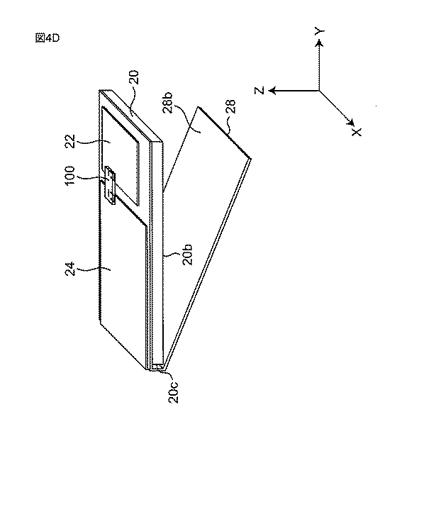
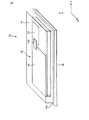
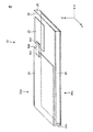
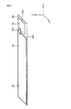
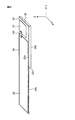
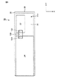
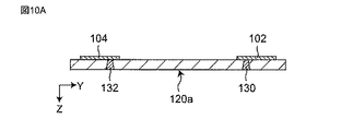
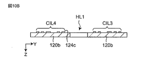
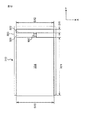
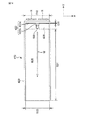
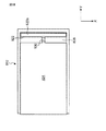
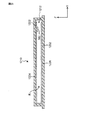
20a 表面
20b 裏面
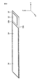
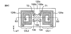
22 第1の放射電極
24 第2の放射電極
26 裏面電極
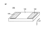
100 RFIC素子
102 第1の端子電極
104 第2の端子電極
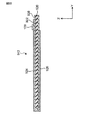
Claims (22)
- 物品の金属面に取り付けられた状態で使用可能な無線通信デバイスであって、
第1および第2の端子電極を備えるRFIC素子と、
前記RFIC素子の前記第1の端子電極に接続されている第1の放射電極と、
前記第1の放射電極に対して独立した状態で、前記第1の放射電極と同層に設けられ、前記RFIC素子の前記第2の端子電極に接続されている第2の放射電極と、
前記第2の放射電極に対して距離をあけて対向するように設けられ、前記第2の放射電極に接続され、且つ前記金属面に対向するように前記金属面に取り付けられる裏面電極と、を有し、
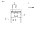
前記第1および第2の放射電極が第1の方向に距離をあけて前記同層上で対向し、
前記第2の放射電極において、前記第1の方向のサイズに比べて、前記第1の方向と直交する第2の方向のサイズが小さく、
前記第1の放射電極は、前記第1の端子電極との接続点から見て、一方向に延在する第1の帯状部と前記一方向とは反対方向に延在する第2の帯状部とを備え、
前記第1および第2の帯状部は、前記第2の放射電極に対して前記第2の方向に対向することなくそれぞれ延在し、
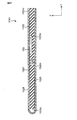
前記第1の放射電極の面積が、前記第2の放射電極の面積に比べて小さい、無線通信デバイス。 - 表面と裏面とを備える誘電体基板を有し、
前記第1および第2の放射電極が前記誘電体基板の前記表面上に設けられ、
前記裏面電極が前記誘電体基板の前記裏面上に設けられている、請求項1に記載の無線通信デバイス。 - 前記誘電体基板、前記第1の放射電極、前記第2の放射電極、前記裏面電極、および前記RFIC素子が可撓性を備える、請求項2に記載の無線通信デバイス。
- 前記第1および第2の放射電極と前記裏面電極との間が空気層である、請求項1に記載の無線通信デバイス。
- 前記裏面電極および前記第2の放射電極は、一つの金属膜によって構成されている、請求項1から4のいずれか一項に記載の無線通信デバイス。
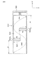
- 前記第2の放射電極と前記裏面電極が、前記誘電体基板の一端で折り返された1つの金属シートによって構成され、
前記誘電体基板の前記一端に、前記誘電体基板に比べて高い剛性を備え、且つ、前記金属シートの折り目の延在方向に延在する芯部材が設けられている、請求項2に記載の無線通信デバイス。 - 前記裏面電極が前記第1の放射電極に対して対向しないように設けられている、請求項1から6のいずれか一項に記載の無線通信デバイス。
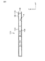
- 前記RFIC素子が、
前記第1および第2の端子電極を備える素子基板と、
前記素子基板上に設けられたRFICチップと、
前記素子基板上に設けられ、前記RFICチップと前記第1および第2の放射電極との間でインピーダンス整合をとるための整合回路とを備える、請求項1から7のいずれか一項に記載の無線通信デバイス。 - 前記第1の放射電極が、前記第2の放射電極に比べて小さい幅で前記RFIC素子から離れる方向に延在している、請求項1から8のいずれか一項に記載の無線通信デバイス。
- 前記第1の放射電極の前記第1の方向のサイズが前記第2の方向のサイズに比べて小さい、請求項9に記載の無線通信デバイス。
- 前記第2の放射電極が、前記第1の放射電極と前記第1の方向に対向する部分に対して前記第1の方向の反対側の部分で、前記裏面電極に接続する、請求項10に記載の無線通信デバイス。
- 前記第1の放射電極の第1の方向のサイズが、前記第2の放射電極の第2の方向のサイズに比べて小さい、請求項10または11に記載の無線通信デバイス。
- 前記第2の放射電極が、前記第2の方向の一方の端に設けられて前記第2の方向の中央に向かって延在する第1の切り欠き部を備える、請求項10から12のいずれか一項に記載の無線通信デバイス。
- 前記第2の放射電極が、前記第2の方向の他方の端に設けられて前記第2の方向の中央に向かって延在する第2の切り欠き部を備え、
前記第1の切り欠き部と前記第2の切り欠き部とが、前記第1の方向に間隔をあけて並んでいる、請求項13に記載の無線通信デバイス。 - 前記第1の方向について、前記第1の放射電極のサイズが前記第2の放射電極のサイズの50分の1に比べて小さい、請求項10から14のいずれか一項に記載の無線通信デバイス。
- 前記第1の方向について、前記第1の放射電極のサイズが前記第2の放射電極のサイズの100分の1に比べて小さい、請求項15に記載の無線通信デバイス。
- 前記第1の放射電極が、前記第2の方向の両端それぞれから前記第1の方向に延在する折れ曲がり部を備える、請求項10から16のいずれか一項に記載の無線通信デバイス。
- 前記第1の放射電極が、貫通穴を備える、請求項1から17のいずれか一項に記載の無線通信デバイス。
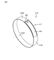
- 前記裏面電極に対して対向するように設けられ、非磁性金属材料から作製され、且つ物品に対して取り付けられるときに使用される取り付け部を有する、請求項1から18のいずれか一項に記載の無線通信デバイス。
- 前記取り付け部がリング状である、請求項19に記載の無線通信デバイス。
- 少なくとも一部に金属面を備え、前記金属面に取り付けられた無線通信デバイスを有する物品であって、
前記無線通信デバイスが、
第1および第2の端子電極を備えるRFIC素子と、
前記RFIC素子の前記第1の端子電極に接続されている第1の放射電極と、
前記第1の放射電極に対して独立した状態で、前記第1の放射電極と同層に設けられ、
前記RFIC素子の前記第2の端子電極に接続されている第2の放射電極と、
前記第2の放射電極に対して距離をあけて対向するように設けられ、前記第2の放射電極に接続されている裏面電極と、を有し、
前記第1および第2の放射電極が第1の方向に距離をあけて前記同層上で対向し、
前記第2の放射電極において、前記第1の方向のサイズに比べて、前記第1の方向と直交する第2の方向のサイズが小さく、
前記第1の放射電極は、前記第1の端子電極との接続点から見て、一方向に延在する第1の帯状部と前記一方向とは反対方向に延在する第2の帯状部とを備え、
前記第1および第2の帯状部は、前記第2の放射電極に対して前記第2の方向に対向することなくそれぞれ延在し、
前記無線通信デバイスが、前記裏面電極が前記金属面に対向するように前記金属面に取り付けられ、
前記第1の放射電極の面積が、前記第2の放射電極の面積に比べて小さい、物品。 - 前記物品の金属面が、非磁性金属材料の表面である、請求項21に記載の物品。
Applications Claiming Priority (5)
| Application Number | Priority Date | Filing Date | Title |
|---|---|---|---|
| JP2015143881 | 2015-07-21 | ||
| JP2015143881 | 2015-07-21 | ||
| JP2016034658 | 2016-02-25 | ||
| JP2016034658 | 2016-02-25 | ||
| PCT/JP2016/070861 WO2017014151A1 (ja) | 2015-07-21 | 2016-07-14 | 無線通信デバイスおよびそれを備えた物品 |
Publications (2)
| Publication Number | Publication Date |
|---|---|
| JPWO2017014151A1 JPWO2017014151A1 (ja) | 2017-07-20 |
| JP6288317B2 true JP6288317B2 (ja) | 2018-03-07 |
Family
ID=57834846
Family Applications (1)
| Application Number | Title | Priority Date | Filing Date |
|---|---|---|---|
| JP2016575711A Active JP6288317B2 (ja) | 2015-07-21 | 2016-07-14 | 無線通信デバイスおよびそれを備えた物品 |
Country Status (5)
| Country | Link |
|---|---|
| US (1) | US10726322B2 (ja) |
| JP (1) | JP6288317B2 (ja) |
| CN (1) | CN208385636U (ja) |
| DE (2) | DE212016000146U1 (ja) |
| WO (1) | WO2017014151A1 (ja) |
Families Citing this family (9)
| Publication number | Priority date | Publication date | Assignee | Title |
|---|---|---|---|---|
| CN102668241B (zh) * | 2010-03-24 | 2015-01-28 | 株式会社村田制作所 | Rfid系统 |
| CN209963236U (zh) | 2017-09-29 | 2020-01-17 | 株式会社村田制作所 | 无线通信器件 |
| CN211236956U (zh) * | 2018-07-13 | 2020-08-11 | 株式会社村田制作所 | 无线通信器件 |
| WO2021090530A1 (ja) * | 2019-11-08 | 2021-05-14 | 株式会社村田製作所 | Rficモジュール及びrfidタグ |
| DE212020000743U1 (de) * | 2019-12-24 | 2022-07-21 | Murata Manufacturing Co., Ltd | Kommunikationsvorrichtung |
| CN115879496B (zh) * | 2021-09-28 | 2025-10-17 | 华为技术有限公司 | 通信标签和电子设备 |
| JP7765824B2 (ja) * | 2022-02-09 | 2025-11-07 | 立山科学株式会社 | Rfタグ |
| CN114976596A (zh) * | 2022-05-24 | 2022-08-30 | 深圳市信维通信股份有限公司 | 天线模组和通信设备以及天线模组的制造方法 |
| US12506282B2 (en) * | 2022-11-24 | 2025-12-23 | Murata Manufacturing Co., Ltd. | Antenna device |
Family Cites Families (33)
| Publication number | Priority date | Publication date | Assignee | Title |
|---|---|---|---|---|
| JPS5170156A (ja) | 1974-12-14 | 1976-06-17 | Kobe Steel Ltd | Yosetsuyokontakutochitsupu |
| TW381057B (en) | 1997-08-07 | 2000-02-01 | Hitachi Ltd | Semiconductor device |
| US6018299A (en) | 1998-06-09 | 2000-01-25 | Motorola, Inc. | Radio frequency identification tag having a printed antenna and method |
| JP3645239B2 (ja) * | 2002-09-06 | 2005-05-11 | シャープ株式会社 | ダイポールアンテナ、それを用いたタグ及び移動体識別システム |
| JP4326936B2 (ja) * | 2003-12-24 | 2009-09-09 | シャープ株式会社 | 無線タグ |
| JP4653440B2 (ja) * | 2004-08-13 | 2011-03-16 | 富士通株式会社 | Rfidタグおよびその製造方法 |
| JP2006222873A (ja) * | 2005-02-14 | 2006-08-24 | Tohoku Univ | アンテナ、通信装置及びアンテナの製造方法 |
| KR100983571B1 (ko) | 2005-06-16 | 2010-09-24 | 후지쯔 가부시끼가이샤 | 태그 안테나 및 rfid 태그 |
| EP1898488A4 (en) | 2005-06-28 | 2009-07-08 | Fujitsu Ltd | HIGH FREQUENCY IDENTIFICATION LABEL |
| JP4226642B2 (ja) | 2005-09-02 | 2009-02-18 | 富士通株式会社 | Rfタグ及びrfタグを製造する方法 |
| NZ549173A (en) * | 2006-08-15 | 2007-06-29 | Times 7 Holdings Ltd | Licence plate with integrated antenna |
| WO2008096574A1 (ja) | 2007-02-06 | 2008-08-14 | Murata Manufacturing Co., Ltd. | 電磁結合モジュール付き包装材 |
| PL2126799T3 (pl) * | 2007-03-23 | 2018-10-31 | Zih Corp. | Etykieta rfid o zmniejszonym rozstrajaniu |
| JP4997007B2 (ja) | 2007-07-19 | 2012-08-08 | トッパン・フォームズ株式会社 | Rf−idメディア及びその製造方法 |
| US7880614B2 (en) * | 2007-09-26 | 2011-02-01 | Avery Dennison Corporation | RFID interposer with impedance matching |
| US9300032B2 (en) | 2007-10-31 | 2016-03-29 | Tyco Fire & Security Gmbh | RFID antenna system and method |
| TWI382595B (zh) * | 2008-09-16 | 2013-01-11 | Polychem Uv Eb Internat Corp | Antenna construction of RFID transponder and its manufacturing method |
| TWI376840B (en) * | 2008-12-25 | 2012-11-11 | Arcadyan Technology Corp | Dipole antenna |
| US8384599B2 (en) * | 2009-02-13 | 2013-02-26 | William N. Carr | Multiple-cavity antenna |
| WO2010093475A1 (en) * | 2009-02-13 | 2010-08-19 | Carr William N | Multiple-cavity antenna |
| JP5510450B2 (ja) | 2009-04-14 | 2014-06-04 | 株式会社村田製作所 | 無線icデバイス |
| JP5328508B2 (ja) * | 2009-06-23 | 2013-10-30 | トッパン・フォームズ株式会社 | 非接触型データ受送信体 |
| JP5291552B2 (ja) | 2009-06-30 | 2013-09-18 | トッパン・フォームズ株式会社 | 非接触型データ受送信体 |
| US8581793B2 (en) | 2009-08-05 | 2013-11-12 | William N. Carr | RFID antenna with asymmetrical structure and method of making same |
| JP5304580B2 (ja) | 2009-10-02 | 2013-10-02 | 株式会社村田製作所 | 無線icデバイス |
| JP5526726B2 (ja) | 2009-11-20 | 2014-06-18 | 富士通株式会社 | 無線タグ |
| JP5170156B2 (ja) | 2010-05-14 | 2013-03-27 | 株式会社村田製作所 | 無線icデバイス |
| JP2012137894A (ja) | 2010-12-25 | 2012-07-19 | Murata Mfg Co Ltd | 無線icデバイス |
| JP2012146000A (ja) | 2011-01-07 | 2012-08-02 | Murata Mfg Co Ltd | 無線icデバイス |
| JP5304956B2 (ja) | 2011-01-14 | 2013-10-02 | 株式会社村田製作所 | Rfidチップパッケージ及びrfidタグ |
| JP2014143591A (ja) | 2013-01-24 | 2014-08-07 | Nippon Dengyo Kosaku Co Ltd | アレイアンテナ |
| US9172130B2 (en) * | 2013-03-13 | 2015-10-27 | Avery Dennison Corporation | RFID inlay incorporating a ground plane |
| JP2014220739A (ja) * | 2013-05-10 | 2014-11-20 | 東京コスモス電機株式会社 | プリント基板ダイポールアンテナ |
-
2016
- 2016-07-14 DE DE212016000146.9U patent/DE212016000146U1/de active Active
- 2016-07-14 JP JP2016575711A patent/JP6288317B2/ja active Active
- 2016-07-14 CN CN201690001023.7U patent/CN208385636U/zh active Active
- 2016-07-14 WO PCT/JP2016/070861 patent/WO2017014151A1/ja not_active Ceased
- 2016-07-14 DE DE112016004557.3T patent/DE112016004557B4/de active Active
-
2018
- 2018-01-12 US US15/869,530 patent/US10726322B2/en active Active
Also Published As
| Publication number | Publication date |
|---|---|
| US20180137399A1 (en) | 2018-05-17 |
| CN208385636U (zh) | 2019-01-15 |
| DE112016004557T5 (de) | 2018-06-21 |
| WO2017014151A1 (ja) | 2017-01-26 |
| US10726322B2 (en) | 2020-07-28 |
| JPWO2017014151A1 (ja) | 2017-07-20 |
| DE112016004557B4 (de) | 2023-03-02 |
| DE212016000146U1 (de) | 2018-03-12 |
Similar Documents
| Publication | Publication Date | Title |
|---|---|---|
| JP6288317B2 (ja) | 無線通信デバイスおよびそれを備えた物品 | |
| CN102204112B (zh) | 无线通信装置 | |
| US8847844B2 (en) | Antenna and antenna module | |
| US9727765B2 (en) | RFID system including a reader/writer and RFID tag | |
| JP6288318B2 (ja) | 無線通信デバイスおよびそれを備えた物品 | |
| US9825361B2 (en) | Antenna with multifrequency capability for miniaturized applications | |
| US10387764B2 (en) | RFID tag, article including the same, and RFID tag manufacturing method | |
| JP5703977B2 (ja) | 無線通信デバイス付き金属物品 | |
| JP6512385B2 (ja) | Rfidタグ | |
| JP6590122B1 (ja) | Rfidタグ、および、rfidタグが取り付けられた物品 | |
| US20190081383A1 (en) | Wireless communication device | |
| WO2011062238A1 (ja) | アンテナ装置及び移動体通信端末 | |
| US8770489B2 (en) | Radio communication device | |
| US20140131455A1 (en) | Antenna and wireless tag | |
| US20140292611A1 (en) | Antenna apparatus | |
| JP2014533057A (ja) | アンテナ構造体、及びアンテナ構造体を備えるrfidトランスポンダシステム | |
| JPWO2019065957A1 (ja) | 無線通信デバイス | |
| JP5724671B2 (ja) | アンテナ装置、rfidタグおよび通信端末装置 | |
| US20130341415A1 (en) | Wireless ic device | |
| JP2019192951A (ja) | アンテナ装置および電子機器 | |
| JP2012252664A (ja) | 無線通信デバイス、その製造方法及び無線通信デバイス付き金属物品 | |
| US12136011B2 (en) | Container including RFID module | |
| US20230359847A1 (en) | Container including rfid module | |
| JP5886100B2 (ja) | 無線icタグ | |
| JPWO2020012726A1 (ja) | 無線通信デバイスおよびその製造方法 |
Legal Events
| Date | Code | Title | Description |
|---|---|---|---|
| A521 | Request for written amendment filed |
Free format text: JAPANESE INTERMEDIATE CODE: A523 Effective date: 20161227 |
|
| A621 | Written request for application examination |
Free format text: JAPANESE INTERMEDIATE CODE: A621 Effective date: 20161227 |
|
| A871 | Explanation of circumstances concerning accelerated examination |
Free format text: JAPANESE INTERMEDIATE CODE: A871 Effective date: 20161227 |
|
| A975 | Report on accelerated examination |
Free format text: JAPANESE INTERMEDIATE CODE: A971005 Effective date: 20170207 |
|
| A131 | Notification of reasons for refusal |
Free format text: JAPANESE INTERMEDIATE CODE: A131 Effective date: 20170221 |
|
| A601 | Written request for extension of time |
Free format text: JAPANESE INTERMEDIATE CODE: A601 Effective date: 20170420 |
|
| A521 | Request for written amendment filed |
Free format text: JAPANESE INTERMEDIATE CODE: A523 Effective date: 20170511 |
|
| A131 | Notification of reasons for refusal |
Free format text: JAPANESE INTERMEDIATE CODE: A131 Effective date: 20170808 |
|
| A521 | Request for written amendment filed |
Free format text: JAPANESE INTERMEDIATE CODE: A523 Effective date: 20171006 |
|
| TRDD | Decision of grant or rejection written | ||
| A01 | Written decision to grant a patent or to grant a registration (utility model) |
Free format text: JAPANESE INTERMEDIATE CODE: A01 Effective date: 20180109 |
|
| A61 | First payment of annual fees (during grant procedure) |
Free format text: JAPANESE INTERMEDIATE CODE: A61 Effective date: 20180122 |
|
| R150 | Certificate of patent or registration of utility model |
Ref document number: 6288317 Country of ref document: JP Free format text: JAPANESE INTERMEDIATE CODE: R150 |