JP6242527B1 - Steel pipe joint structure for pile construction - Google Patents
Steel pipe joint structure for pile construction Download PDFInfo
- Publication number
- JP6242527B1 JP6242527B1 JP2017107219A JP2017107219A JP6242527B1 JP 6242527 B1 JP6242527 B1 JP 6242527B1 JP 2017107219 A JP2017107219 A JP 2017107219A JP 2017107219 A JP2017107219 A JP 2017107219A JP 6242527 B1 JP6242527 B1 JP 6242527B1
- Authority
- JP
- Japan
- Prior art keywords
- steel pipe
- flange
- joint structure
- pile
- flanges
- Prior art date
- Legal status (The legal status is an assumption and is not a legal conclusion. Google has not performed a legal analysis and makes no representation as to the accuracy of the status listed.)
- Expired - Fee Related
Links
Images


Abstract
【課題】鋼管杭等のように鋼管を地盤に回転圧入により貫入する工程を伴う杭施工の際に、短尺の鋼管同士を接合する鋼管接合構造として、大きな回転トルクを伝達可能な鋼管接合構造を提供する。【解決手段】接合すべき一方の鋼管1の端部と他方の鋼管2の端部とに、互いにボルト接合可能なフランジ3、4をそれぞれ溶接固定してなり、各フランジ3、4はドーナツ形のフランジ基部(フランジ基板5)上に、回転方向に互いに当接可能な複数(図示例では2つ)の凸部(扇形凸部6)を設ける。両フランジ3、4は凸部6において互いに当接するので、単なる平板フランジ同士をボルト接合する構造と異なり、小径ボルトでボルト接合しても大きな回転トルクの伝達が可能となる。鋼管外周面から張り出すフランジ幅をあまり広くせずに済む。【選択図】図3[PROBLEMS] To provide a steel pipe joint structure capable of transmitting a large rotational torque as a steel pipe joint structure for joining short steel pipes in a pile construction involving a process of inserting a steel pipe into the ground by rotary press fitting such as a steel pipe pile. provide. Flanges that can be bolted to each other are welded and fixed to the end of one steel pipe to be joined and the end of the other steel pipe, respectively, and each flange has a donut shape. A plurality of (two in the illustrated example) convex portions (fan-shaped convex portions 6) that can contact each other in the rotational direction are provided on the flange base portion (flange substrate 5). Since both the flanges 3 and 4 abut against each other at the convex portion 6, a large rotational torque can be transmitted even if the small-diameter bolts are bolted, unlike a structure in which flat plate flanges are bolted together. It is not necessary to widen the flange width protruding from the outer peripheral surface of the steel pipe. [Selection] Figure 3
Description
この発明は、鋼管を地盤に回転圧入により貫入する工程を伴う杭施工の際に、短尺の鋼管同士を接合する杭施工用の鋼管接合構造に関する。 The present invention relates to a steel pipe joint structure for pile construction in which short steel pipes are joined to each other in a pile construction involving a step of inserting a steel pipe into the ground by rotational press-fitting.
杭施工法として鋼管を地盤に回転圧入により貫入する工程を伴う種々の工法がある。この種の杭施工法として、例えば鋼管杭の施工であれば、地盤に貫入する鋼管杭として必要な長さのままでは通常、搬送や施工等に支障があるので、施工現場で複数の短尺の鋼管同士を直接溶接接合して1本の鋼管杭とすることが行われている。
この溶接接合による接合方式は、溶接技能者を確保しなければならない、溶接部の品質管理を必要とする、溶接作業に長時間を要する、これらからコストアップとなる等の問題があり、溶接接合でない種々の鋼管接合構造が提案されている。
As a pile construction method, there are various methods involving a process of inserting a steel pipe into the ground by rotary press-fitting. As this type of pile construction method, for example, if steel pipe piles are constructed, the length required for steel pipe piles penetrating into the ground is usually hindered in transportation and construction. It has been practiced to weld steel pipes directly to form a single steel pipe pile.
This method of joining by welding has the following problems: welding engineers must be secured, quality control of the welded part is required, welding work takes a long time, and costs increase from these. Various steel pipe joint structures have been proposed.
特許文献1(特開2011−157731)の接合構造は、鋼管の端部にフランジを溶接固定しフランジ同士をボルトで接合するフランジ接合構造である。このフランジ接合構造は、一般的なフランジ接合構造であって、単なるドーナツ形平板であるフランジにボルト孔をあけた平板フランジを鋼管端部に溶接固定して、ボルト孔を通したボルトで平板フランジ同士を締め付けて接合するものであり、両フランジ間の摩擦力によって回転トルクを伝達する。
この特許文献1は、通常の鋼管杭の施工では、地盤を掘削しながら鋼管を回転圧入させなければならず、鋼管同士の接続部に大きな力が作用するので、鋼管同士を強固に接続しなければならず、接続部の構成が複雑になるという背景のもとに、地盤を改良してソイルセメントを製造しておき、このソイルセメント内に鋼管杭を挿入するというものである(特許文献1の[0004]参照)。
The joining structure of patent document 1 (Unexamined-Japanese-Patent No. 2011-157731) is a flange joining structure which welds and fixes a flange to the edge part of a steel pipe, and joins flanges with a volt | bolt. This flange joint structure is a general flange joint structure. A flat flange with a bolt hole formed in a flange that is a simple donut-shaped flat plate is welded and fixed to the end of the steel pipe, and the flat flange is formed with a bolt through the bolt hole. They are fastened together and transmit rotational torque by the frictional force between both flanges.
In this
フランジ接合構造の特殊なものとして、特許文献2(特開2013−112953)、特許文献3(特開2011−69072)のように、傾斜した半月板形フランジを管端部に溶接固定し、傾斜半月板形フランジ同士をボルトで接合する特殊形状のものもある。 As a special flange joint structure, as shown in Patent Document 2 (Japanese Patent Laid-Open No. 2013-112953) and Patent Document 3 (Japanese Patent Laid-Open No. 2011-69072), an inclined meniscus flange is fixed to the pipe end by welding. There is also a special shape that joins meniscus flanges with bolts.
特許文献4(特開2011−52396)の接合構造は、一方の鋼管の端部に雄ねじ継手、他方の鋼管の端部に雌ねじ継手をそれぞれ工場にて溶接固定しておき、施工現場では一方の鋼管の雄ねじ継手と他方の鋼管の雌ねじ継手とを螺合させることで、2つの鋼管を接合するというものである。 In the joining structure of Patent Document 4 (Japanese Patent Laid-Open No. 2011-52396), a male threaded joint is attached to the end of one steel pipe and a female threaded joint is secured to the end of the other steel pipe at the factory. The two steel pipes are joined by screwing the male thread joint of the steel pipe and the female thread joint of the other steel pipe.
特許文献5(特開2002−294694)の接合構造は、2つの鋼管杭の端部どうしを互いに突き合わせ、その突合せ部の外側に鋼管スリーブをその径方向に圧縮した状態に取り付けるという接合構造である。この場合、鋼管スリーブの材質および/または断面形状を、鋼管スリーブが鋼管より先に塑性変形するように選定する。これにより、ねじ式などの機械式接合や溶接接合を使わずに、鋼管杭のような肉厚の相当厚い鋼管もきわめて簡単に接合できるとされる。 The joining structure of patent document 5 (Unexamined-Japanese-Patent No. 2002-294694) is a joining structure where the edge part of two steel pipe piles is faced | matched mutually, and the steel pipe sleeve is attached to the state compressed in the radial direction on the outer side of the abutting part. . In this case, the material and / or cross-sectional shape of the steel pipe sleeve is selected so that the steel pipe sleeve is plastically deformed before the steel pipe. As a result, it is said that a considerably thick steel pipe such as a steel pipe pile can be joined very easily without using mechanical joining such as a screw type or welding joining.
溶接接合以外の接合構造として、特許文献1〜5以外にも多くの接合構造が提案されている。例えば、特許文献6(特開2009−191522)、特許文献7(特開2006−299665)、特許文献8(特開2008−69611)、特許文献9(特開2011−69071)等があるが、いずれもかなり複雑な構造を採用するものであり、それらの説明は省略する。
Many joining structures other than
鋼管端部に溶接固定した単なる平板フランジ同士をボルトで接合する特許文献1の鋼管接合構造の場合、回転圧入の際の回転トルクはフランジ間の摩擦力で伝達されるが、フランジ間の摩擦力を大にするためにはボルトの締付け力を大にする必要がある。そのために大径のボルトを使用するとボルト孔を大きくすることが必要となるが、鋼管外面から張り出すフランジ幅は通常あまり幅広にすることができないので、大径のボルトを用いることができない場合がある。また、高力ボルトを用いても大径にしなければ強度を満たすことができない場合がある。
In the case of the steel pipe joint structure of
特許文献2、3の鋼管接合構造は、半月板形フランジを鋼管に傾斜させて溶接固定するものであるから、半月板形フランジを鋼管の適切な位置に適切に傾斜させて精度よく溶接固定することは必ずしも簡単とは思えないので製作が繁雑であり、コストも高くなる。
この接合構造は、掘削の推進力増大の作用を期待したものと思われるが、それを特に期待しない場合には無用に繁雑になる上、大きな回転トルクを伝達可能とは思えない。
Since the steel pipe joint structures of
This joint structure seems to be expected to increase the driving force of excavation. However, if this is not particularly expected, it becomes unnecessarily complicated and it cannot be considered that a large rotational torque can be transmitted.
特許文献4のネジ式の鋼管接合構造は、回転圧入工法を採用して施工する場合、ネジが締まる方向の回転のみの場合はよいが、逆回転を必要とする場合(引き抜くため)にはネジが緩むので採用できない。
The screw-type steel pipe joint structure of
特許文献5の鋼管スリーブ圧縮方式の鋼管接合構造は、管軸方向及び回転方向の接合強度の安定性の確保、及び接合強度管理が難しいと思われる。
The steel pipe joint structure of the steel pipe sleeve compression method of
特許文献6〜9等の複雑な接合構造は、使用する部品の製造コストが高くなり、かつ施工も繁雑で施工費が高くなる。
The complicated joint structures such as
本発明は上記背景のもとになされたもので、施工現場での溶接接合が不要であり、回転圧入の際の大きな回転トルクを伝達することが可能であり、部品の製造コストが安く済み、施工も繁雑にならずに施工コストが安く済む杭施工用の鋼管接合構造を提供することを目的とする。 The present invention was made based on the above-mentioned background, does not require welding on the construction site, can transmit a large rotational torque at the time of rotational press-fitting, and the manufacturing cost of parts can be reduced. The purpose of the present invention is to provide a steel pipe joint structure for pile construction that does not require complicated construction and can reduce construction costs.
上記課題を解決する請求項1の発明は、鋼管を地盤に回転圧入により貫入する工程を伴う杭施工の際に、短尺の鋼管同士を接合する杭施工用の鋼管接合構造であって、
接合すべき一方の鋼管の端部と他方の鋼管の端部とに、互いにボルト接合可能なフランジをそれぞれ溶接固定してなり、各フランジは、ドーナツ形のフランジ基部上に、回転方向に互いに当接可能な複数の凸部が形成されてなり、各フランジの前記複数の凸部が、いずれも扇形状の輪郭をなす扇形凸部であることを特徴とする。
Invention of
The flanges that can be bolted to each other are welded and fixed to the end of one steel pipe to be joined and the end of the other steel pipe, respectively, and the flanges contact each other in the rotational direction on a donut-shaped flange base. Ri Na plurality of projections capable contact is formed, the plurality of convex portions of each flange, characterized in that both a sector convex portion forms a fan-shaped contour.
請求項2は、請求項1の杭施工用の鋼管接合構造において、前記各フランジは、前記ドーナツ形のフランジ基部が平板状のフランジ基板であり、このフランジ基板上に円周方向に間隔をあけて前記扇形凸部を形成するための扇形板を溶接固定してなることを特徴とする。
請求項3は、請求項1又は2の杭施工用の鋼管接合構造において、鋼管杭を地盤に回転圧入して鋼管杭を施工する際に、前記鋼管杭を構成する短尺の鋼管同士を接合する鋼管接合構造であることを特徴とする。
請求項4は、請求項1又は2の杭施工用の鋼管接合構造において、ケーシング鋼管を地盤に回転圧入し、セメント系注入材を注入した後、前記ケーシング鋼管を引き抜いて柱状地盤改良体を施工する際に、前記ケーシング鋼管を構成する短尺の鋼管同士を接合する鋼管接合構造であることを特徴とする。
本発明の鋼管接合構造を採用して行う杭施工において、鋼管を地盤に回転圧入する際、一方の鋼管と他方の鋼管との接合部における回転トルクの伝達はそれぞれの端部に固定されたフランジ間で伝達されるが、それぞれのフランジが、ドーナツ形のフランジ基部上に、回転方向に互いに当接可能な複数の凸部が形成されている構造なので、回転トルクの伝達は各フランジの互いに当接する凸部において行われる。この互いに当接する凸部による回転トルク伝達によれば、極めて大きな回転トルクの伝達が可能である。 In pile construction performed by adopting the steel pipe joint structure of the present invention, when rotationally press-fitting a steel pipe into the ground, transmission of rotational torque at the joint between one steel pipe and the other steel pipe is a flange fixed to each end. However, each flange has a structure in which a plurality of convex portions that can contact each other in the rotational direction are formed on the donut-shaped flange base. It is performed at the convex part which touches. According to the rotational torque transmission by the convex portions that are in contact with each other, a very large rotational torque can be transmitted.
したがって、両フランジを連結するボルトは、特許文献1のような単なる平板フランジ同士をボルト接合するものと異なり、両フランジ間に大きな摩擦力を発生させるための特に強い締め付け力を要求されない。したがって、大径のボルトを用いる必要がなくフランジに大きなボルト孔を開ける必要がない。杭施工用の鋼管接合構造の場合、鋼管外面から張り出すフランジ幅をあまり広く取れない場合があるので、大径のボルトを必要としないことは極めて有利である。また、フランジ幅の問題に限らず小径のボルトで済むこと自体に、部品コスト、作業性その他種々の点で有利である。
Therefore, the bolt that connects the two flanges is not required to have a particularly strong tightening force for generating a large frictional force between the flanges, unlike a bolt that simply joins flat plate flanges as in
なお、大径のボルトを用いるのではなく強力な締め付け力が可能な高力ボルトを用いることで対応できる場合もあるにしても、高力ボルトは高価であり、また、締付トルク管理(例えばトルクメータを用いて行う)を必要とするが、本発明によればボルトが安価で済み、また特別な締付トルク管理を必要としない。 Note that high-strength bolts are expensive, and tightening torque management (e.g., for example) may be possible by using high-strength bolts capable of strong tightening force instead of using large-diameter bolts. However, according to the present invention, the bolt can be inexpensive and no special tightening torque management is required.
特許文献2、3の半月板形フランジ方式の鋼管接合構造のように鋼管に傾斜半月板形フランジを溶接固定する方式と異なり、同じフランジ接合方式でも本発明の鋼管接合構造は極めてシンプルであり、コストも安価に済む。また、大きな回転トルクを伝達可能である。
Unlike the method of welding and fixing the inclined meniscus flange to the steel pipe like the steel pipe joint structure of the meniscus flange method of
また、特許文献4のネジ接合方式では、逆方向の回転に対してネジが緩むので回転トルクの伝達が一方向に限られるが、本発明の鋼管接合構造によれば、正逆両方向の回転方向に対して回転トルクを伝達することができる。したがって、一旦地盤に貫入した鋼管(ケーシング鋼管)を引き抜く工程のある杭施工法を実施する場合にも適用できる。
Further, in the screw joint method of
特許文献5の鋼管スリーブ圧縮方式の鋼管接合構造は、管軸方向及び回転方向の接合強度の安定性の確保、及び接合強度管理が難しいが、本発明の鋼管接合構造によれば、そのような問題は全くなく、回転方向の接合強度は明確である。
In the steel pipe sleeve compression type steel pipe joint structure of
特許文献6〜9等の複雑な接合構造のように、使用する部品の製造コストが高く、かつ施工も繁雑で施工費も高くなる接合構造と異なり、本発明の鋼管接合構造は極めてシンプルであり、部品のコストも安く、かつ施工も容易で施工費も安く済む。
Unlike the joining structures that are expensive to manufacture parts, such as the complicated joining structures of
以下、本発明の杭施工用の鋼管接合構造を実施するための形態について、図面を参照して説明する。 Hereinafter, the form for implementing the steel pipe joining structure for pile construction of this invention is demonstrated with reference to drawings.
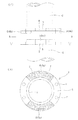
図1は本発明の一実施例の杭施工用の鋼管接合構造10を示すもので、(イ)は上下の鋼管1、2のフランジ接合部の正面図、(ロ)は(イ)のA−A断面図である。
下側の鋼管1にフランジ3が溶接固定され、上側の鋼管2にフランジ4が溶接固定され、両鋼管1、2はそれぞれのフランジ3、4をボルト8を締め付けることでフランジ接合される。
図2(イ)は図1(イ)において、上下の鋼管のフランジ3、4がボルト接合される前の離間した状態で示した図、(ロ)は(イ)のB−B矢視図である。
図3(イ)は図2(イ)の下側鋼管1のフランジ接合部を斜視図で示した図、(ロ)は図2(イ)の上側鋼管4のフランジ接合部を上下逆向きにして斜視図で示した図である。
FIG. 1 shows a steel pipe
The
FIG. 2 (a) is a diagram showing the state in which the
3 (a) is a perspective view of the flange joint portion of the
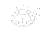
前記2つのフランジ3、4はそれ自体としては同一形状のものであり、図4に示すように、各フランジ3(4)は、ドーナツ形平板であるフランジ基板(フランジ基部)5上に、扇形凸部として扇形板6を溶接固定した構造である。その溶接固定は例えば扇形板6の外周及び内周で行うとよいが、さらに両端でおこなってもよい。なお、図1〜図3においては、下側鋼管1のフランジ3の扇形板6を6a、上側鋼管2のフランジ4の扇形板6を6bで区別する。図2(ロ)において扇形板6の部分を砂地ハッチングで示している。
図示例の各扇形板6はドーナツ形平板を概ね4分割(4等分)した平面形状であり、各フランジ3、4は、2つの扇形板6がそれぞれのフランジ基板5上に対向する態様で溶接固定された構造である。なお、各扇形板6は、上下のフランジ3、4を接合する際に上下の扇形板6が互いに干渉しないように90°より僅かに小さな角度(θ=88°)の扇形としている。フランジ基板5に扇形板6を溶接固定した部分も同じ符号で扇形凸部6と呼ぶ。
各フランジ3、4には、ボルト8を挿通させるボルト挿通孔7を周方向に等間隔で8つ設けており、両フランジ3、4は各扇形凸部6毎に2カ所でボルト接合される。なお、図では、フランジ基板5のみにあけられたボルト挿通孔と扇形凸部6の部分(2枚重ねの部分)にあけられたボルト挿通孔とを区別せずに同じ符号7で示している。
実施例のフランジ3、4の各部の寸法は、外径D=320mm、内径d=218mmである。フランジ基板5の板厚が20mm、扇形板6の板厚も20mm、ボルト挿通孔7の孔径は23mm、ボルト挿通孔7の位置は半径R=140mmの位置である。
なお、上記フランジ3、4のサイズは、杭の軸径(鋼管径)が216.3mmの場合のものであるが、例えば外径267.4mm、318.5mm、355.6mm、406.4mm、457.2mm等の大径の軸径の場合には、フランジサイズはそれに対応する大径のものとなる。本発明の鋼管接合構造は大きな回転トルクを伝達可能なので、軸径が大サイズである場合に特に有効である。
The two
Each fan-shaped
Eight
The dimension of each part of the
The sizes of the
上述した実施例の鋼管接合構造10を採用して行う杭施工において、鋼管を地盤に回転圧入する際、下側の鋼管1と上側の鋼管2との接合部における回転トルクの伝達はそれぞれの端部に固定されたフランジ3、4間で伝達されるが、それぞれのフランジ3、4が、ドーナツ形のフランジ基板5上に、回転方向に互いに当接可能な複数の扇形凸部6が形成されている構造なので、回転トルクの伝達は各フランジ3、4の互いに当接する扇形凸部6において行われる。この互いに当接する扇形凸部6による回転トルク伝達によれば、極めて大きな回転トルクの伝達が可能である。
上記実施例の鋼管接合構造10によれば、[発明の効果]の段落で説明した通りの種々の効果を奏する
In the pile construction performed by adopting the steel pipe
According to the steel pipe
上述した鋼管接合構造10は、鋼管杭を地盤に回転圧入して鋼管杭を施工する際に、前記鋼管杭を構成する短尺の鋼管同士を接合する鋼管接合構造として用いることができる。
鋼管杭を施工する場合、例えば図7(イ)に示すように、鋼管先端に例えば掘削刃や掘削翼付き端面板等を持つ掘削ヘッド20を溶接固定した鋼管杭21を図示略の回転圧入駆動装置で地盤に回転圧入により貫入する。なお、図示例の掘削ヘッド20は、掘削翼付き端面板として中央部が杭頭側に凹んだ形状の掘削翼付き端面板を用いているが、勿論、平板状の掘削翼付き端面板でもよい(後述する図7(ロ)の掘削ヘッド40についても同じ)。
鋼管杭に用いる鋼管として必要な長さのままでは通常、搬送や施工等に支障があるので、複数の短尺の鋼管を用いるが、実施例の鋼管接合構造10は、杭先端側である下側の短尺の鋼管1とその上側の短尺の鋼管2との接合に使用されている。短尺の鋼管を2本以上継ぎ足す必要がある場合には、2点鎖線で示すように下端にフランジ3を溶接固定した鋼管30をさらに接合する。
The steel pipe
When constructing a steel pipe pile, for example, as shown in FIG. 7 (a), a
Since the length required for the steel pipe used for the steel pipe pile is usually hindered in transportation and construction, a plurality of short steel pipes are used. However, the steel pipe
上述した鋼管接合構造10は、ケーシング鋼管を地盤に回転圧入し、セメント系注入材を注入した後、前記ケーシング鋼管を引き抜いて柱状地盤改良体を施工する際に、前記ケーシング鋼管を構成する短尺の鋼管同士を接合する鋼管接合構造として用いることができる。
ケーシング鋼管を地盤に回転圧入する場合、例えば図7(ロ)に示すように、ケーシング鋼管41の先端に、例えば掘削刃や掘削翼付き端面板等を持つとともに鋼管先端から離脱可能な構造の掘削ヘッド40を取り付ける。この掘削ヘッド40は、ケーシング鋼管41の貫入時にはケーシング鋼管41と一体に回転するが、セメント系注入材を注入した後ケーシング鋼管41を引き抜く際に貫入時と逆方向に回転させると、ケーシング鋼管41から離脱して掘削孔底に残される。
この場合も、ケーシング鋼管41として通常、図示のように短尺の鋼管を接合して用いる必要があるので、前記と同様に、ケーシング鋼管先端側である下側の短尺の鋼管1とその上側の短尺の鋼管2とを実施例の鋼管接合構造10により接合することができる。
The steel pipe
When the casing steel pipe is rotationally press-fitted into the ground, for example, as shown in FIG. 7 (b), the excavation having a structure that has a drilling blade, an end face plate with excavating blades, and the like at the tip of the
Also in this case, since it is usually necessary to join and use a short steel pipe as shown in the figure as the
なお、柱状地盤改良体を施工する場合として、セメント系注入材に代えてソイルセメント等を注入する工法の場合にも、短尺鋼管どうしを接合する構造として本発明の鋼管接合構造を適用できる。 In addition, as a case where the columnar ground improvement body is constructed, the steel pipe joining structure of the present invention can be applied as a structure for joining short steel pipes even in the case of a method of injecting soil cement or the like instead of the cement-based injecting material.
上述の実施例の鋼管接合構造10におけるフランジ3、4は、ドーナツ形平板であるフランジ基板(フランジ基部)5に扇形板(扇形凸部6)を溶接固定して構成したが、図5に示すように、フランジ基部5’と扇形凸部6’とが一体に鋳造されたフランジ3’(4’)であってもよい。
The
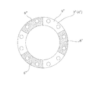
図1〜図4で説明したフランジ3、4は、扇形凸部となる扇形板6がドーナツ形平板を概ね4分割(4等分)した平面形状であるが、図6に示したフランジ3”(4”)のように、ドーナツ形平板を概ね6分割(6等分)した平面形状の扇形板6”であってもよいし、分割数はこれらに限らない(扇形板6”の部分を砂地ハッチングで示した)。フランジ基板を5”で示す。
また、互いに当接する扇形凸部は、必ずしも実施例のように互いに嵌合するような態様で当接する構造に限らず、回転トルクを伝達可能に当接するものであればよい。実施例のように互いに嵌合するような扇形凸部(扇形角度88°の扇形板)6であれば、伝達可能な回転トルクを特に大にすることができるが、回転トルク伝達には上側フランジ4の扇形凸部6の回転方向後端側(当接する側と反対側)にはスペースがあってもよいので、適宜の扇形角度を採用することができる。
The
Further, the fan-shaped convex portions that are in contact with each other are not necessarily limited to the structure in which they are in contact with each other as in the embodiment, but may be any one that makes contact so that rotational torque can be transmitted. The fan-shaped convex portions (fan-shaped plates having a fan-shaped angle of 88 °) 6 that can be fitted to each other as in the embodiment can particularly increase the rotational torque that can be transmitted. Since there may be a space on the rotation direction rear end side (the side opposite to the abutting side) of the four fan-shaped
1、2 鋼管
3、3’、3” フランジ(下側鋼管のフランジ)
4、4’、4” フランジ(上側鋼管のフランジ)
5、5” フランジ基板(フランジ基部)
6、6’、6” 扇形板(扇形凸部)
7 ボルト挿通孔
8 ボルト
10 鋼管接合構造
20 (鋼管杭先端に溶接固定した)掘削ヘッド
21 鋼管杭
40 (ケーシング先端に離脱可能に取り付けた)掘削ヘッド
41 ケーシング鋼管
1, 2
4, 4 ', 4 "flange (upper steel pipe flange)
5, 5 "flange substrate (flange base)
6, 6 ', 6 "fan-shaped plate (fan-shaped convex part)
7 Bolt insertion hole 8
Claims (4)
接合すべき一方の鋼管の端部と他方の鋼管の端部とに、互いにボルト接合可能なフランジをそれぞれ溶接固定してなり、各フランジは、ドーナツ形のフランジ基部上に、回転方向に互いに当接可能な複数の凸部が形成されてなり、各フランジの前記複数の凸部が、いずれも扇形状の輪郭をなす扇形凸部であることを特徴とする。 A steel pipe joint structure for pile construction that joins short steel pipes to each other during pile construction with a process of inserting the steel pipe into the ground by rotational press-fit,
The flanges that can be bolted to each other are welded and fixed to the end of one steel pipe to be joined and the end of the other steel pipe, respectively, and the flanges contact each other in the rotational direction on a donut-shaped flange base. Ri Na plurality of projections capable contact is formed, the plurality of convex portions of each flange, characterized in that both a sector convex portion forms a fan-shaped contour.
Priority Applications (1)
| Application Number | Priority Date | Filing Date | Title |
|---|---|---|---|
| JP2017107219A JP6242527B1 (en) | 2017-05-30 | 2017-05-30 | Steel pipe joint structure for pile construction |
Applications Claiming Priority (1)
| Application Number | Priority Date | Filing Date | Title |
|---|---|---|---|
| JP2017107219A JP6242527B1 (en) | 2017-05-30 | 2017-05-30 | Steel pipe joint structure for pile construction |
Publications (2)
| Publication Number | Publication Date |
|---|---|
| JP6242527B1 true JP6242527B1 (en) | 2017-12-06 |
| JP2018204187A JP2018204187A (en) | 2018-12-27 |
Family
ID=60570445
Family Applications (1)
| Application Number | Title | Priority Date | Filing Date |
|---|---|---|---|
| JP2017107219A Expired - Fee Related JP6242527B1 (en) | 2017-05-30 | 2017-05-30 | Steel pipe joint structure for pile construction |
Country Status (1)
| Country | Link |
|---|---|
| JP (1) | JP6242527B1 (en) |
Cited By (2)
| Publication number | Priority date | Publication date | Assignee | Title |
|---|---|---|---|---|
| CN109590744A (en) * | 2019-01-18 | 2019-04-09 | 中交第三航务工程局有限公司 | A kind of welding procedure of offshore wind power foundation steel-pipe pile |
| JP2019203346A (en) * | 2018-05-25 | 2019-11-28 | 株式会社横河Nsエンジニアリング | Steel pipe pile, joint of steel pipe pile, and projection type member for weld-joining |
Families Citing this family (4)
| Publication number | Priority date | Publication date | Assignee | Title |
|---|---|---|---|---|
| JP7406307B2 (en) * | 2019-03-29 | 2023-12-27 | 日鉄建材株式会社 | Liquefaction countermeasure construction method using drainage pipes and drainage pipes |
| JP6567793B1 (en) * | 2019-06-10 | 2019-08-28 | 株式会社シグマベース | Pile steel pipe joint structure |
| JP6916338B1 (en) * | 2020-03-31 | 2021-08-11 | 若築建設株式会社 | Steel pipe pile removal device |
| JP7082173B1 (en) | 2020-12-01 | 2022-06-07 | 株式会社ビル技研 | How to correct the height shortage of screw piles |
Citations (9)
| Publication number | Priority date | Publication date | Assignee | Title |
|---|---|---|---|---|
| JPS48179Y1 (en) * | 1968-07-04 | 1973-01-06 | ||
| JPH09158176A (en) * | 1995-12-01 | 1997-06-17 | Shintoku Kogyo Kk | Connection metallic material of pile |
| JP2002161532A (en) * | 2000-11-24 | 2002-06-04 | Daiwa House Ind Co Ltd | Joint structure for upper and lower joints |
| JP2002302940A (en) * | 2001-04-09 | 2002-10-18 | Norio Moriya | Connection structure for foundation pile |
| JP2003105752A (en) * | 2001-09-28 | 2003-04-09 | Kawasaki Steel Corp | Connecting structure of steel pipe |
| JP2006002560A (en) * | 2004-05-19 | 2006-01-05 | Kajima Road Co Ltd | Joint device |
| US20120087740A1 (en) * | 2006-09-08 | 2012-04-12 | Ben Stroyer | Auger grouted displacement pile |
| JP2014091929A (en) * | 2012-11-01 | 2014-05-19 | Chiyoda Soiltec Co Ltd | Ground reinforcing method with small-diameter cast-in-place concrete pile |
| US9151010B2 (en) * | 2012-10-08 | 2015-10-06 | Chin Chai Ong | Article for joining concrete piles |
-
2017
- 2017-05-30 JP JP2017107219A patent/JP6242527B1/en not_active Expired - Fee Related
Patent Citations (9)
| Publication number | Priority date | Publication date | Assignee | Title |
|---|---|---|---|---|
| JPS48179Y1 (en) * | 1968-07-04 | 1973-01-06 | ||
| JPH09158176A (en) * | 1995-12-01 | 1997-06-17 | Shintoku Kogyo Kk | Connection metallic material of pile |
| JP2002161532A (en) * | 2000-11-24 | 2002-06-04 | Daiwa House Ind Co Ltd | Joint structure for upper and lower joints |
| JP2002302940A (en) * | 2001-04-09 | 2002-10-18 | Norio Moriya | Connection structure for foundation pile |
| JP2003105752A (en) * | 2001-09-28 | 2003-04-09 | Kawasaki Steel Corp | Connecting structure of steel pipe |
| JP2006002560A (en) * | 2004-05-19 | 2006-01-05 | Kajima Road Co Ltd | Joint device |
| US20120087740A1 (en) * | 2006-09-08 | 2012-04-12 | Ben Stroyer | Auger grouted displacement pile |
| US9151010B2 (en) * | 2012-10-08 | 2015-10-06 | Chin Chai Ong | Article for joining concrete piles |
| JP2014091929A (en) * | 2012-11-01 | 2014-05-19 | Chiyoda Soiltec Co Ltd | Ground reinforcing method with small-diameter cast-in-place concrete pile |
Cited By (2)
| Publication number | Priority date | Publication date | Assignee | Title |
|---|---|---|---|---|
| JP2019203346A (en) * | 2018-05-25 | 2019-11-28 | 株式会社横河Nsエンジニアリング | Steel pipe pile, joint of steel pipe pile, and projection type member for weld-joining |
| CN109590744A (en) * | 2019-01-18 | 2019-04-09 | 中交第三航务工程局有限公司 | A kind of welding procedure of offshore wind power foundation steel-pipe pile |
Also Published As
| Publication number | Publication date |
|---|---|
| JP2018204187A (en) | 2018-12-27 |
Similar Documents
| Publication | Publication Date | Title |
|---|---|---|
| JP6242527B1 (en) | Steel pipe joint structure for pile construction | |
| JP5053828B2 (en) | Joint structure | |
| JP5140114B2 (en) | Joining method of ready-made piles, Joined hardware of ready-made piles | |
| JP3135948U (en) | Steel pipe pile joint structure | |
| KR102164316B1 (en) | micro-pile boring casings pipe for one shot grouting | |
| JP2008274613A (en) | Connecting structure of steel pipe pile | |
| JP2013112953A (en) | Steel pipe pile connection structure | |
| JP5831874B2 (en) | Method for connecting foundation piles for housing with an outer diameter of 115 to 320 mm | |
| JP2020158990A (en) | Steel pipe connection structure | |
| JP2017048670A (en) | Auger shaft connection structure | |
| KR20160001116U (en) | Coulper of steel pipe pile for rotational intrusion and pullout | |
| JP2016044476A (en) | Joint structure of steel pipe for casting and connection method for the steel pipe for casting | |
| JP2009024436A (en) | Mechanical joint of steel pipe pile | |
| JPH11247183A (en) | Screwing type steel pipe pile with wing and its execution | |
| KR200481009Y1 (en) | Coulper of steel pipe pile for rotational intrusion and pullout | |
| JP5829729B1 (en) | Penetration device for steel pipe pile with tip wing | |
| JP2020139337A (en) | Pile steel pipe | |
| JP4609627B2 (en) | Joining method of ready-made piles, Joined hardware of ready-made piles | |
| JP6856370B2 (en) | Casing coupling structure | |
| JP2010168789A (en) | Mechanical coupling for steel pipe pile | |
| JP3753360B2 (en) | Steel pipe pile cascade | |
| JP6470699B2 (en) | Pile connection structure | |
| KR200430880Y1 (en) | Double row casing joint | |
| JP6567793B1 (en) | Pile steel pipe joint structure | |
| JP2006188889A (en) | Joint structure of pile |
Legal Events
| Date | Code | Title | Description |
|---|---|---|---|
| A131 | Notification of reasons for refusal |
Free format text: JAPANESE INTERMEDIATE CODE: A131 Effective date: 20170830 |
|
| A521 | Request for written amendment filed |
Free format text: JAPANESE INTERMEDIATE CODE: A523 Effective date: 20170913 |
|
| TRDD | Decision of grant or rejection written | ||
| A01 | Written decision to grant a patent or to grant a registration (utility model) |
Free format text: JAPANESE INTERMEDIATE CODE: A01 Effective date: 20171102 |
|
| A61 | First payment of annual fees (during grant procedure) |
Free format text: JAPANESE INTERMEDIATE CODE: A61 Effective date: 20171107 |
|
| R150 | Certificate of patent or registration of utility model |
Ref document number: 6242527 Country of ref document: JP Free format text: JAPANESE INTERMEDIATE CODE: R150 |
|
| S531 | Written request for registration of change of domicile |
Free format text: JAPANESE INTERMEDIATE CODE: R313531 |
|
| R350 | Written notification of registration of transfer |
Free format text: JAPANESE INTERMEDIATE CODE: R350 |
|
| LAPS | Cancellation because of no payment of annual fees |