JP3753360B2 - Steel pipe pile cascade - Google Patents
Steel pipe pile cascade Download PDFInfo
- Publication number
- JP3753360B2 JP3753360B2 JP2000012589A JP2000012589A JP3753360B2 JP 3753360 B2 JP3753360 B2 JP 3753360B2 JP 2000012589 A JP2000012589 A JP 2000012589A JP 2000012589 A JP2000012589 A JP 2000012589A JP 3753360 B2 JP3753360 B2 JP 3753360B2
- Authority
- JP
- Japan
- Prior art keywords
- steel pipe
- joint material
- pipe pile
- fitting
- pile
- Prior art date
- Legal status (The legal status is an assumption and is not a legal conclusion. Google has not performed a legal analysis and makes no representation as to the accuracy of the status listed.)
- Expired - Lifetime
Links
Images


Description
【0001】
【産業上の利用分野】
本発明は、鋼管杭(鋼管矢板を含む)の沈設工法において行われる鋼管杭どうしの縦継ぎに広く適用でき、特に、中掘り工法その等の鋼管杭を回転圧入により沈設の縦する工法や沈設にあたって鋼管杭に回転を与える他の工法においての鋼管杭継ぎに好適な、鋼管杭の縦継ぎ装置に関するものである。
【0002】
【従来の技術】
鋼管杭の沈設を行う工法としては、一般に、打撃を加えて行う打込み工法や、既設の掘削孔に挿入するプレボーリング工法、あるいは鋼管杭に挿入したオーガーで掘削しながら鋼管杭を回転圧入して行く中掘り工法、その他鋼管杭を回転圧入だけで沈設する工法や合成鋼管杭等の工法があるが、近頃では中堀り工法が多く採用されている。
【0003】
また、鋼管杭の沈設施工では、製作、運搬等の都合から、定尺物の鋼管杭を現場に搬入し、沈設過程の下杭に対して上杭をクレーンで吊り下げて突き合わせて溶接により縦継ぎしながら施工を進め、所定長さの鋼管杭の沈設を行うようにしており、この縦継ぎには溶接による方法が採られている。
【0004】
この溶接による縦継ぎは、現場溶接であるため、作業に多くの時間を要するとともに熟練した溶接工が必要となり、また、溶接部の品質が天候に左右されるばかりでなく、溶接に伴う裏当てリング等の金具を使用する等面倒で多くの費用を要している。そこで、溶接による縦継ぎに代わるものとして、上杭と下杭をネジ継手によって結合する方法(一例として実開昭57-133645号、実開昭57-98923号、特開平4-70414号工法参照)が提案されている。
【0005】
【発明が解決しようとする課題】
しかし、ネジ継手による縦継ぎ方法は、製作が面倒でコスト高になる。しかも、鋼管杭の縦継ぎは、下杭に上杭を吊り降ろして行うため、吊り降ろしながら螺合のために回転させることは極めて困難な作業となる。しかも、鋼管杭を回転圧入により沈設する工法においては、施工時に逆回転させることがあり、そのような場合にはネジが緩んでしまうため、このネジ螺合による縦継ぎ方法は採用することができない。
【0006】
本発明は、かかる問題を解決するためになされたもので、鋼管杭の溶接やネジ螺合による方法に代わって、縦継ぎが、特殊な機械や技能を用いることなく、強固にかつ簡便に行えるとともに、上杭、下杭が回転不能に結合でき、中堀り工法にも使用することのできる、機械的手段による鋼管杭の縦継ぎ装置を提供しようとするものである。
【0007】
【課題を解決するための手段】
上記の目的を達成するために、請求項1の発明は、鋼管杭の一端に突設する雄形のピン継手材、及びこの鋼管杭と縦継ぎする他方の鋼管杭の接続側端部に突設する前記雄型のピン継手材と嵌合する雌形のボックス継手材を備える鋼管杭の縦継ぎ装置において、前記雄型のピン継手材の外周及び前記雌型のボックス継手材の外周に、杭の回転圧入による埋設施工時に両継手材の相対回転を不能とする嵌め合せ手段が突出して設けられることを特徴とする。
【0008】
請求項2の発明は、請求項1に記載の鋼管杭の縦継ぎ装置において、前記雄形のピン継手材及び前記雌型のボックス継手材は、前記鋼管杭の厚さよりも厚肉の厚肉部を有し、該厚肉部の外周に前記嵌め合せ手段が設けられたことを特徴とする。
【0009】
請求項3の発明は、請求項1又は2に記載の鋼管杭の縦継ぎ装置において、前記嵌め合せ手段が前記雄型のピン継手材の外周に突設された回転付与金具と、前記雌型のボックス継手材の外周に突設された回転受金具とから成ることを特徴とする。
請求項4の発明は、請求項3に記載の鋼管杭の縦継ぎ装置において、前記回転付与金具と前記回転受金具を結合する手段が両金具に設けられたことを特徴とする。
【0010】
【発明の実施の形態】
以下、本発明の実施の形態について図面を参照して説明する。図1〜図6は本発明の第1の装置の実施例を示し、図7、図8は同第2の装置の実施例を示したものである。
【0011】
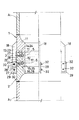
まず、第1の装置について説明する。図1〜図4において、A1は上杭となる鋼管杭、A2は下杭となる鋼管杭である。上杭A1には、下杭A2と結合される端部に、円筒状をなす雄形のピン継手材1が溶接により下方に突設され、また、下杭A2には、上杭A1と接続結合される端部に、上記ピン継手材1を受け入れて嵌合する円筒状をなす雌形のボックス継手材2が溶接により突設されている。
【0012】
ピン継手材1は、外径を上杭A1の外径とほぼ同径とした基筒部11に続き、その先端の接合端面13を介して、基筒部11より十分小径とした嵌挿筒部12が下方に向け延設され、接合端面13と嵌挿筒部12の外周と交差する隅部には、凹溝14が周設されている。また、嵌挿筒部12の端部には、後述するボックス継手材2内周の受面25と凹条26に接合する端面15と凸条16が周設されている。そして、嵌挿筒部13の外周には、上下に間隔をおいて複数の外溝条17が周設されている。さらに、基筒部11の外周には、ボックス継手材2の外側に向けて延長する2枚一組の回転付与金具18、18が所要の間隔をおいて突設されており、この金具18、18の組は周方向に複数隔設されている。
【0013】
ボックス継手材2は、外径を下杭A2の外径とほぼ同とした基筒部21に続きその先端に、内周を上記嵌挿筒部12の外周に接して嵌挿筒部12に外嵌する嵌受筒部22が先方に向け延設されており、その先端には、嵌挿筒部12の接合端面13を受ける端面23と凹溝14と嵌合する凸条24が設けられ、また、基筒部21と嵌受筒部22との段部には、嵌挿筒部12の端面15を受ける受面25と凸条16と嵌合する凹溝26が設けられている。
【0014】
そして、嵌受筒部22の内周には、上記嵌挿筒部12の外溝条17と対応する位置に、外溝条17より十分深くした内溝条27が周設されているとともに、各内溝条27には、嵌受筒部22の外周より連通するネジ孔28が、それぞれ周方向に間隔をおいて複数設けられている。さらに、ボックス継手材2の外周には、上記2枚組の回転付与金具18,18の間に突入できる回転受金具29が、上記回転付与金具18,18に対応して周方向に複数隔設されている。
【0015】
また、上記の各内溝条27内には、ネジ孔28に螺合させたセットボルト3の操作によって、内溝条27内から対向する外溝条17内に跨る位置まで進退する円弧キー5が収容されている。この円弧キー5を進退させる構造は、例えば図3(イ)、(ロ)に示すように、セットボルト3は、その基端部にネジ孔28と螺合する右ネジの頭部3aを有し、先端部に円弧キー5に設けた左ネジ(逆ネジ)と螺合する尾部3bを有しており、セットボルト3を正(右)回転させてネジ込めば円弧キー5が前進し、逆(左)回転させれば円弧キー5が後退するようになっている。なお、円弧キー5を進退させる構造はこれに限定されるものではない。
【0016】
上杭A1と下杭A2とを縦継ぎするには、上杭A1をクレーンで吊り上げ、下杭A2の直上に運んで吊り降ろし、ボックス継手材2嵌受筒部22内にピン継手材1の嵌挿筒部12を挿入して行けば、ピン継手材1の端面13と凹溝14及び端面15と凸条16が、ボックス継手材2の端面23と凹溝24及び受面25と凹溝26とそれぞれ嵌合して、両継手材1,2を介して上杭A1と下杭A2との嵌合による結合力が強化され、特に曲げ抗力が増大されることになる。その際、上杭A2の回転調整によって、ピン継手材1の2枚一組の回転付与金具18,18間に、ボックス継手材2の回転受金具29が挿入されるようにする。それによって上下両杭A1、A2は相互に回転不能な嵌め合せとなる。
【0017】
なお、回転付与金具18と回転受金具29は、上記とは反対に、回転付与金具18をボックス継手材2の方に、回転受金具29の方をピン継手材1の方に設けることができる。
【0018】
図5は、上記第1の装置の他の実施例を示したものである。上記の実施例では、両継手材1,2はその外径が上下両杭A1,A2とほぼ同径としているが、この実施例では、両継手材1,2がその内径が両杭1,2の内径とほぼ同径としているとともに、その外径が両杭1,2の外径より大径となっている。この実施例のものは、結合した両杭1,2の中に、継手材1,2の出張りがないので、中掘り工法により杭の埋設を行う場合に、オーガスクリューの挿入、掘削及び掘削土砂の搬送が円滑に行えるという利点がある。その他の構成は、さきの実施例におけると同様であるから、その説明は省略する。
【0019】
また、上記の実施例では、上杭A1と下杭A2とは同径となっているが、第1の装置では異径杭どうしの縦継ぎにも適用できる。例えば、図6に示すように、上杭A1が小径で下杭A2が大径であってもよい。また、これとは反対に、上杭A1が大径で下杭A2が小径であってもよい。その他の構成はさきの実施例におけると同様であるから、その説明は省略する。
【0020】
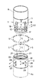
次に、本発明の第2の装置について説明する。図7、図8はその一実施例を示したものである。この第2の装置は、上記第1の装置に対しその回転力伝達の強化を図ったもので、特に、硬質の地盤や粘性の高い地盤等、回転負荷の大きな地盤での施工に適している。
【0021】
この装置では、図7、図8に示したように、ピン継手材1の外周に取り付けた回転付与金具18、18の組及びこれに対応してボックス継手材2に取り付けた回転受金具29の取り付け数が増加され、それぞれ両継手材1,2の外周の4分割個所に設けたものとなっている。なお、それら回転付与金具18,29の取り付け数は、4個所以上に増加することができる。また、それら回転付与金具18と回転受金具29の互いに係合する個所に対向してボルトの挿通孔30,31を設けておく。そして、両金具18,29が係合した際、それらの孔30,31を通してボルト・ナット32により両金具18,29を結合する。なお、その他の構成に関しては、第1の装置におけると同様であるから、その説明については省略する。
【0022】
なお、上記第1、第2の装置の各実施例では、上杭の方にピン継手材1を設け、下杭の方にボックス継手材2を設けたものとなっているが、これとは反対に、上杭の方にボックス継手材2を、下杭の方にピン継手材1を設けた構造とすることができる。また、内、外溝条17,21は、各複数段設けられているが、これは、1段以上必要な段数設けることができる。
【0023】
【発明の効果】
以上説明したように、本発明によれば、鋼管杭である上杭と下杭の縦継ぎにおいて、一方の杭に突設したピン継手材と他方の杭に突設したボックス継手材とを挿嵌して、互いにそれらの接合面に設けた内、外溝条に収容した円弧キーを、外部からの操作によって、内、外両溝条に跨って契合されるようにしたので、上下両杭の縦継ぎが極めて簡単な作業で能率よく行うことができ、従来の溶接やネジ継手の方法に比べて施工性が大巾に向上される。
【0024】
そして、上、下両杭は、その縦継ぎ時に、それらに設けられた回転付与金具と回転受金具とを係合させるという簡便な作業により、互いに回転不能の関係を保つことができ、杭の回転圧入による埋設施工が確実に行えることになる。
【図面の簡単な説明】
【図1】本発明第1の装置の一実施例を示す半部截断側面図である。
【図2】同半部平断面図である。
【図3】同円弧キーによる契合部分の拡大側断面図で、(イ)は契合前の状態を示し、(ロ)は契合時の状態を示す。
【図4】同上杭と下杭の端部を離して示した斜視図である。
【図5】同他の実施例を示す半部側断面図である。
【図6】同さらに他の実施例を示す半部側断面図である。
【図7】本発明第2の装置の一実施例を示す半部截断側面図である。
【図8】同上杭と下杭の端部を離して示した斜視図である。
【符号の説明】
A1 上杭
A2 下杭
1 ピン継手材
2 ボックス継手材
11 基筒部
12 嵌挿筒部
13 接合端面
14 凹溝
15 先端面
16 凸条
17 外溝条
18 回転付与金具
21 基筒部
22 嵌受筒部
23 端面
24 凸条
25 受面
26 凹溝
27 内溝条
28 ネジ孔
29 回転受金具
30,31 ボルト挿通孔
32 ボルト・ナット[0001]
[Industrial application fields]
INDUSTRIAL APPLICABILITY The present invention can be widely applied to the longitudinal joining of steel pipe piles carried out in a steel pipe pile (including steel pipe sheet piles) construction method. The present invention relates to a longitudinally connecting device for steel pipe piles, which is suitable for steel pipe pile joints in other construction methods that rotate steel pipe piles.
[0002]
[Prior art]
In general, steel pipe piles are laid down by using a hammering method, a pre-boring method that is inserted into an existing excavation hole, or by rotating and pressing a steel pipe pile while excavating with an auger inserted into the steel pipe pile. There are methods such as the going digging method, other methods such as substituting steel pipe piles only by rotary press-fitting, and synthetic steel pipe piles. Recently, the digging method is often used.
[0003]
In addition, for the construction of steel pipe piles, for the purpose of production and transportation, steel pipe piles of a fixed size are carried to the site, the upper pile is suspended with a crane against the lower pile, and the vertical pile is welded. Construction is carried out while joining, and a steel pipe pile having a predetermined length is set up. A welding method is used for this longitudinal joining.
[0004]
Since this welding is a field welding, it takes a lot of time to work and requires a skilled welder, and the quality of the weld is not only affected by the weather, but also supports the welding. It is troublesome to use metal fittings such as a ring and requires a lot of expenses. Therefore, as an alternative to the longitudinal joint by welding, the upper pile and the lower pile are joined by screw joints (see, for example, Utility Model 57-133645, Utility Model 57-98923, Japanese Patent Application Laid-Open Hei 4-70414) ) Has been proposed.
[0005]
[Problems to be solved by the invention]
However, the longitudinal joining method using a threaded joint is cumbersome to manufacture and expensive. In addition, since the longitudinal connection of the steel pipe pile is performed by hanging the upper pile from the lower pile, it is extremely difficult to rotate for screwing while hanging. Moreover, in the construction method of laying steel pipe piles by rotary press-fitting, there is a case where the steel pipe pile is reversely rotated at the time of construction, and in such a case, the screw is loosened. .
[0006]
The present invention has been made to solve such a problem. Instead of a method of welding a steel pipe pile or screwing, a longitudinal connection can be performed firmly and easily without using a special machine or skill. At the same time, an object of the present invention is to provide a longitudinally connecting device for steel pipe piles by mechanical means, in which the upper pile and the lower pile can be coupled in a non-rotatable manner and can also be used for the intermediate excavation method.
[0007]
[Means for Solving the Problems]
In order to achieve the above object, the invention of
[0008]
According to a second aspect of the present invention, in the longitudinal connection device for a steel pipe pile according to the first aspect, the male pin joint material and the female box joint material are thicker than the thickness of the steel pipe pile. And the fitting means is provided on the outer periphery of the thick part .
[0009]
The invention according to
According to a fourth aspect of the present invention, in the longitudinally connecting device for steel pipe piles according to the third aspect of the present invention, means for coupling the rotation applying metal fitting and the rotation metal fitting is provided on both metal fittings.
[0010]
DETAILED DESCRIPTION OF THE INVENTION
Embodiments of the present invention will be described below with reference to the drawings. 1 to 6 show an embodiment of the first device of the present invention, and FIGS. 7 and 8 show an embodiment of the second device.
[0011]
First, the first device will be described. In FIGS 4, A 1 is a steel pipe pile, A 2 to be Uekui are steel pipe serving as a Shitakui. The upper pile A 1 has a cylindrical male pin
[0012]
The pin
[0013]
The
[0014]
And, on the inner periphery of the
[0015]
In each of the
[0016]
To jointed the upper pile A 1 and Shitakui A 2 are lifting the upper pile A 1 by a crane, down hanging carried directly above the lower pile A 2, the pin in the box
[0017]
The rotation imparting
[0018]
FIG. 5 shows another embodiment of the first device. In the above embodiment, both
[0019]
In the above embodiment, although a same diameter and the upper pile A 1 and Shitakui A 2, in the first device can be applied to jointed of each other different径杭. For example, as shown in FIG. 6, the upper pile A 1 is a lower pile A 2 in diameter may be larger in diameter. Furthermore, contrary to this, the upper pile A 1 is a lower pile A 2 a larger diameter may be small. Since other configurations are the same as those in the previous embodiment, the description thereof is omitted.
[0020]
Next, the second apparatus of the present invention will be described. 7 and 8 show one embodiment. This second device is designed to reinforce its rotational force transmission compared to the first device, and is particularly suitable for construction on hard ground or highly viscous ground such as highly viscous ground. .
[0021]
In this apparatus, as shown in FIGS. 7 and 8, a pair of rotation imparting
[0022]
In addition, in each Example of the said 1st, 2nd apparatus, the pin
[0023]
【The invention's effect】
As described above, according to the present invention, in a longitudinal connection between an upper pile and a lower pile, which are steel pipe piles, a pin joint material projecting from one pile and a box joint material projecting from the other pile are inserted. The upper and lower piles are fitted to the inner and outer grooves of the arc keys accommodated in the outer grooves, which are provided on their joint surfaces. Can be efficiently performed with extremely simple work, and the workability is greatly improved as compared with the conventional welding and screw joint methods.
[0024]
And the upper and lower piles can maintain a non-rotatable relationship with each other by a simple operation of engaging the rotation imparting metal fitting and the rotation metal fitting provided on the piles at the time of the longitudinal connection. The burial work by rotary press fitting can be performed reliably.
[Brief description of the drawings]
FIG. 1 is a half cut-away side view showing an embodiment of the first apparatus of the present invention.
FIG. 2 is a half cross-sectional plan view of the same.
FIGS. 3A and 3B are enlarged side cross-sectional views of an engagement portion using the same arc key. FIG. 3A shows a state before the engagement, and FIG. 3B shows a state at the time of the engagement.
FIG. 4 is a perspective view showing the ends of the upper pile and the lower pile separated from each other.
FIG. 5 is a half side sectional view showing another embodiment.
FIG. 6 is a half sectional side view showing still another embodiment.
FIG. 7 is a half cut-away side view showing an embodiment of the second apparatus of the present invention.
FIG. 8 is a perspective view showing the ends of the upper pile and the lower pile separated from each other.
[Explanation of symbols]
A 1 Upper pile
A 2
11 Base tube
12 Insertion tube
13 Joint end face
14 groove
15 Tip surface
16 ridges
17 Outer groove
18 Rotating bracket
21 Base tube
22 Fitting tube
23 End face
24 ridges
25 Reception surface
26 Groove
27 Inner groove
28 Screw holes
29 Rotating bracket
30, 31 Bolt insertion hole
32 Bolts and nuts
Claims (4)
前記雄型のピン継手材の外周及び前記雌型のボックス継手材の外周に、杭の回転圧入による埋設施工時に両継手材の相対回転を不能とする嵌め合せ手段が突出して設けられることを特徴とする鋼管杭の縦継ぎ装置。A male pin joint material protruding from one end of the steel pipe pile, and a female pin fitting material fitted to the male pin joint material protruding from the connection side end of the other steel pipe pile longitudinally connected to the steel pipe pile. In the steel pipe pile longitudinal connection device with box joint material,
The outer periphery of the male pin joint material and the outer periphery of the female box joint material are provided with fitting means protruding so as not to allow relative rotation of both joint materials at the time of embedding construction by rotary press-fitting of a pile. Steel pipe pile longitudinal connection device.
前記雄形のピン継手材及び前記雌型のボックス継手材は、前記鋼管杭の厚さよりも厚肉の厚肉部を有し、
該厚肉部の外周に前記嵌め合せ手段が設けられたことを特徴とする鋼管杭の縦継ぎ装置。In the longitudinal connection device of the steel pipe pile according to claim 1,
The male pin joint material and the female box joint material have a thick portion thicker than the thickness of the steel pipe pile,
A steel pipe pile longitudinal joining device , wherein the fitting means is provided on the outer periphery of the thick portion .
前記嵌め合せ手段が前記雄型のピン継手材の外周に突設された回転付与金具と、前記雌型のボックス継手材の外周に突設された回転受金具とから成ることを特徴とする鋼管杭の縦継ぎ装置。In the longitudinal connection device of the steel pipe pile according to claim 1 or 2,
The steel pipe characterized in that the fitting means is composed of a rotation imparting fitting projecting on the outer periphery of the male pin joint material and a rotation receiving fitting projecting on the outer periphery of the female box joint material. Pile cascade device.
前記回転付与金具と前記回転受金具を結合する手段が両金具に設けられたことを特徴とする鋼管杭の縦継ぎ装置。A longitudinally connecting device for steel pipe piles, characterized in that means for connecting the rotation imparting metal fitting and the rotation receiving metal fitting is provided on both metal fittings.
Priority Applications (1)
| Application Number | Priority Date | Filing Date | Title |
|---|---|---|---|
| JP2000012589A JP3753360B2 (en) | 2000-01-21 | 2000-01-21 | Steel pipe pile cascade |
Applications Claiming Priority (1)
| Application Number | Priority Date | Filing Date | Title |
|---|---|---|---|
| JP2000012589A JP3753360B2 (en) | 2000-01-21 | 2000-01-21 | Steel pipe pile cascade |
Publications (3)
| Publication Number | Publication Date |
|---|---|
| JP2001200534A JP2001200534A (en) | 2001-07-27 |
| JP2001200534A5 JP2001200534A5 (en) | 2005-09-22 |
| JP3753360B2 true JP3753360B2 (en) | 2006-03-08 |
Family
ID=18540291
Family Applications (1)
| Application Number | Title | Priority Date | Filing Date |
|---|---|---|---|
| JP2000012589A Expired - Lifetime JP3753360B2 (en) | 2000-01-21 | 2000-01-21 | Steel pipe pile cascade |
Country Status (1)
| Country | Link |
|---|---|
| JP (1) | JP3753360B2 (en) |
Families Citing this family (4)
| Publication number | Priority date | Publication date | Assignee | Title |
|---|---|---|---|---|
| JP2003105755A (en) * | 2001-10-02 | 2003-04-09 | Asahi Kasei Corp | Joint structure of different diameter steel pipe piles |
| JP4958890B2 (en) * | 2003-08-28 | 2012-06-20 | 株式会社クボタ | A guide jig for alignment and a method of longitudinal joining of piles using them. |
| JP2009024479A (en) * | 2007-06-20 | 2009-02-05 | Raiteku:Kk | Strut of snowslide/rock fall protective body |
| JP6134430B1 (en) | 2016-10-18 | 2017-05-24 | ウィング工業株式会社 | Steel pipe fitting device |
-
2000
- 2000-01-21 JP JP2000012589A patent/JP3753360B2/en not_active Expired - Lifetime
Also Published As
| Publication number | Publication date |
|---|---|
| JP2001200534A (en) | 2001-07-27 |
Similar Documents
| Publication | Publication Date | Title |
|---|---|---|
| JP3329781B2 (en) | Pillar | |
| KR20200102637A (en) | File coupling structure with spiral plate | |
| JP3753360B2 (en) | Steel pipe pile cascade | |
| JP5140114B2 (en) | Joining method of ready-made piles, Joined hardware of ready-made piles | |
| JPH11344169A (en) | Pipe joint structure | |
| JP3336430B2 (en) | Vertical joints for steel pipe sheet piles | |
| JP3753361B2 (en) | Steel pipe pile cascade | |
| JP3679964B2 (en) | Columnar | |
| JP7190383B2 (en) | Steel pipe connection structure | |
| JP5133334B2 (en) | Columnar | |
| JP3630363B2 (en) | Steel pipe connection equipment | |
| JP4638686B2 (en) | Columnar | |
| JP4609627B2 (en) | Joining method of ready-made piles, Joined hardware of ready-made piles | |
| JP5006950B2 (en) | Columnar | |
| JP2004293231A (en) | Connection structure of steel pipe and its connecting method | |
| JP6470699B2 (en) | Pile connection structure | |
| JP3776055B2 (en) | Columnar | |
| JP4217144B2 (en) | Joint structure for butt connection | |
| JP2004211548A5 (en) | ||
| JP4083466B2 (en) | Fitting | |
| JP4632723B2 (en) | Columnar | |
| JP4347149B2 (en) | Mechanical joint of a longitudinal connection device for piles with means for preventing looseness | |
| JPH06272494A (en) | Segment connecting structure in shield construction method | |
| JPH0742696B2 (en) | Pile sheet pile retaining wall | |
| JP3766834B2 (en) | Grasping fitting that also serves as a mortar injection pipe for tunnel segments |
Legal Events
| Date | Code | Title | Description |
|---|---|---|---|
| A977 | Report on retrieval |
Free format text: JAPANESE INTERMEDIATE CODE: A971007 Effective date: 20050201 |
|
| A521 | Written amendment |
Free format text: JAPANESE INTERMEDIATE CODE: A523 Effective date: 20050414 |
|
| A131 | Notification of reasons for refusal |
Free format text: JAPANESE INTERMEDIATE CODE: A131 Effective date: 20050510 |
|
| A521 | Written amendment |
Free format text: JAPANESE INTERMEDIATE CODE: A523 Effective date: 20050708 |
|
| TRDD | Decision of grant or rejection written | ||
| A01 | Written decision to grant a patent or to grant a registration (utility model) |
Free format text: JAPANESE INTERMEDIATE CODE: A01 Effective date: 20051208 |
|
| A61 | First payment of annual fees (during grant procedure) |
Free format text: JAPANESE INTERMEDIATE CODE: A61 Effective date: 20051209 |
|
| R150 | Certificate of patent or registration of utility model |
Free format text: JAPANESE INTERMEDIATE CODE: R150 Ref document number: 3753360 Country of ref document: JP Free format text: JAPANESE INTERMEDIATE CODE: R150 |
|
| FPAY | Renewal fee payment (event date is renewal date of database) |
Free format text: PAYMENT UNTIL: 20081222 Year of fee payment: 3 |
|
| FPAY | Renewal fee payment (event date is renewal date of database) |
Free format text: PAYMENT UNTIL: 20091222 Year of fee payment: 4 |
|
| FPAY | Renewal fee payment (event date is renewal date of database) |
Free format text: PAYMENT UNTIL: 20091222 Year of fee payment: 4 |
|
| FPAY | Renewal fee payment (event date is renewal date of database) |
Free format text: PAYMENT UNTIL: 20101222 Year of fee payment: 5 |
|
| FPAY | Renewal fee payment (event date is renewal date of database) |
Free format text: PAYMENT UNTIL: 20101222 Year of fee payment: 5 |
|
| FPAY | Renewal fee payment (event date is renewal date of database) |
Free format text: PAYMENT UNTIL: 20111222 Year of fee payment: 6 |
|
| FPAY | Renewal fee payment (event date is renewal date of database) |
Free format text: PAYMENT UNTIL: 20111222 Year of fee payment: 6 |
|
| FPAY | Renewal fee payment (event date is renewal date of database) |
Free format text: PAYMENT UNTIL: 20121222 Year of fee payment: 7 |
|
| FPAY | Renewal fee payment (event date is renewal date of database) |
Free format text: PAYMENT UNTIL: 20131222 Year of fee payment: 8 |
|
| EXPY | Cancellation because of completion of term |