JP5133334B2 - Columnar - Google Patents
Columnar Download PDFInfo
- Publication number
- JP5133334B2 JP5133334B2 JP2009288116A JP2009288116A JP5133334B2 JP 5133334 B2 JP5133334 B2 JP 5133334B2 JP 2009288116 A JP2009288116 A JP 2009288116A JP 2009288116 A JP2009288116 A JP 2009288116A JP 5133334 B2 JP5133334 B2 JP 5133334B2
- Authority
- JP
- Japan
- Prior art keywords
- shaft portion
- columnar body
- peripheral surface
- fitted
- fitting
- Prior art date
- Legal status (The legal status is an assumption and is not a legal conclusion. Google has not performed a legal analysis and makes no representation as to the accuracy of the status listed.)
- Expired - Lifetime
Links
Images


Description
本発明は、支持杭、地滑り杭、土留め柱列杭等の沈設工法、及び構造体の柱等において行われる柱状体どうしの接続に広く適用でき、特に、中堀工法、ソイルセメント合成杭工法、回転埋設杭工法等の柱状体を回転圧入により沈設する工法や沈設にあたって柱状体に回転を与えるその他の工法においての柱状体の接続に好適な柱状体どうしの接続に関し、詳しくは、柱状体の両端部夫々に、隣接する柱状体に対する接続部を設け、柱状体の軸芯方向で隣り合う柱状体の前記接続部どうしを接続自在に構成してある柱状体に関する。 The present invention can be widely applied to a settling method such as a support pile, a landslide pile, a retaining column pile, and a connection between columnar bodies performed in a column of a structure, in particular, a Nakabori method, a soil cement synthetic pile method, Regarding the connection of columnar bodies suitable for connecting columnar bodies in the method of laying columnar bodies by rotary press-fitting and other methods that rotate the columnar bodies during subsidence, such as the rotary buried pile method, for details, see both ends of the columnar bodies. It is related with the columnar body which provided the connection part with respect to an adjacent columnar body in each part, and was comprised so that the said connection part of the columnar body adjacent in the axial center direction of a columnar body was connectable.
柱状体の沈設を行う工法としては、一般に、打撃を加えて行う打込み工法や、既設の掘削孔に挿入するプレボーリング工法、あるいは柱状体に挿入したオーガーで掘削しながら柱状体を回転圧入して行く中掘工法、あるいはソイルセメントを造成しながら柱状体を回転埋設するソイルセメント合成杭工法、あるいは単に柱状体を回転して圧入(埋設)する回転埋設杭工法があるが、近頃では中掘工法が多く採用されている。 In general, the columnar body is sunk by a hammering method, a pre-boring method inserted into an existing excavation hole, or by rotating and pressing the columnar body while excavating with an auger inserted into the columnar body. There is a going-out digging method, a soil-cement synthetic pile method in which a columnar body is rotationally embedded while creating a soil cement, or a rotary embedded pile method in which a columnar body is simply rotated and press-fitted (embedded). Is often adopted.
また、柱状体の沈設施工では、製作、運搬等の都合から、定尺物の柱状体を現場に搬入し、沈設過程の下柱状体に対して上柱状体をクレーンで吊り下げて突き合わせ、溶接により接続しながら施工を進め、所定長さの柱状体の沈設を行うようにしており、この接続には溶接による方法が採られている。 In addition, in the installation work of the columnar body, for the convenience of production, transportation, etc., the columnar body of a standard object is carried to the site, the upper columnar body is suspended from the lower columnar body by the crane and butted, and welded. Construction is carried out while being connected by the method, and a columnar body having a predetermined length is set up. A welding method is used for this connection.
この溶接による接続は、現場溶接であるため、作業に多くの時間を要するとともに熟練した溶接工が必要となり、また、溶接部の品質が天候に左右されるばかりでなく、溶接に伴う裏当てリング等の金具を使用する等面倒で多くの費用を要している。そこで、溶接による接続に代るものとして、上柱状体と下柱状体をネジ継手によって結合する方法が提案されている( 例えば、特許文献1〜3参照) 。
Since this welding connection is on-site welding, it takes a lot of time and requires a skilled welder, and the quality of the weld is not only affected by the weather, but also the backing ring that accompanies the welding. It is cumbersome and requires a lot of expenses, such as using metal fittings. Therefore, as an alternative to the connection by welding, a method of connecting the upper columnar body and the lower columnar body by a threaded joint has been proposed (see, for example,
しかし、ネジ継手による接続方法は、柱状体を回転圧入により沈設する工法においては、施工時に逆回転させることがあり、そのような場合にはネジが緩んでしまうため、このネジ螺合による接続方法は採用することができない。 However, the connection method using a threaded joint is a method in which the columnar body is laid down by rotary press-fitting, and may be rotated in reverse during construction. In such a case, the screw is loosened. Cannot be adopted.
本発明は、かかる問題を解決するためになされたもので、柱状体の溶接やネジ螺合による方法に代って、上柱状体と下柱状体との相対回転を防止して一体回転可能に結合でき、中掘工法、ソイルセメント合成杭工法、回転埋設杭工法等にも使用することのできる柱状体の接続機構を提供しようとするものである。 The present invention has been made to solve such a problem. Instead of the method of welding the columnar body or screwing, the relative rotation between the upper columnar body and the lower columnar body can be prevented to be integrally rotated. An object of the present invention is to provide a connecting mechanism for columnar bodies that can be combined and can be used for a medium excavation method, a soil cement synthetic pile method, a rotary buried pile method, and the like.
本発明の第1特徴構成は、柱状体の両端部夫々に、隣接する柱状体に対する接続部を設け、柱状体の軸芯方向で隣り合う柱状体の前記接続部どうしを接続自在に構成してある柱状体であって、前記柱状体の両端部に設けた両接続部の一方を筒部に形成し、他方を前記筒部に内嵌可能な軸部に形成して、隣接する接続部どうしが嵌合可能に形成し、前記軸部は、隣り合う柱状体の前記筒部と前記軸部とを互いに嵌合した状態で前記筒部に軸芯方向から対向する端面部を備えた基軸部を有し、嵌合した柱状体どうしの軸芯周りにおける相対回転を防止する回り止め機構を備え、前記回り止め機構を、前記筒部及び前記基軸部の外周面よりも内側に備え、前記回り止め機構は、前記筒部と前記軸部との内の何れか一方に、かつ、前記筒部及び前記基軸部の外周面よりも内側に軸芯方向の一端側に向けて開口する凹部を形成し、隣り合う柱状体の前記筒部と前記軸部とを軸芯方向から互いに嵌合させる操作に伴ってのみ前記凹部に嵌合する嵌合キー部材を他方に設けて構成してあるところにある。 The first characteristic configuration of the present invention is such that a connection portion for an adjacent columnar body is provided at each of both ends of the columnar body, and the connection portions of the columnar bodies adjacent in the axial direction of the columnar body are configured to be connectable. A columnar body, wherein one of both connection portions provided at both ends of the columnar body is formed in a cylindrical portion, and the other is formed in a shaft portion that can be fitted into the cylindrical portion, and adjacent connection portions are connected to each other. The shaft portion is provided with an end surface portion facing the tube portion from the axial direction in a state where the tube portion and the shaft portion of adjacent columnar bodies are fitted to each other. has, provided with a detent mechanism for preventing relative rotation in the fitted axis around the columnar bodies to each other, said detent mechanism also comprises inward from the outer peripheral surface of the cylindrical portion and the base shaft portion, the rotation The stop mechanism is provided on any one of the tube portion and the shaft portion, and on the tube portion and the base. With the operation of forming a recess that opens toward one end side in the axial direction inside the outer peripheral surface of the part, and fitting the cylindrical portion and the axial portion of adjacent columnar bodies together from the axial direction Only a fitting key member that fits into the recess is provided on the other side .
〔作用及び効果〕
本発明の第1特徴構成によれば、柱状体の両端部に設けた両接続部の一方を筒部に形成し、他方を前記筒部に内嵌可能な軸部に形成して、隣接する接続部どうしが嵌合可能に形成し、嵌合した柱状体どうしの軸芯周りにおける相対回転を防止する回り止め機構を備えてあるから、隣接する柱状体どうしの相対回転を防止した状態で接続することが可能となった。
つまり、対向する柱状体どうしが接続されると共に、柱状体を回転圧入により沈設する工法において、柱状体を逆回転させたとしても前記回り止め機構によって柱状体どうしの相対回転を防止することができる。
[Action and effect]
According to the first characteristic configuration of the present invention, one of the connection portions provided at both ends of the columnar body is formed in the cylindrical portion, and the other is formed in the shaft portion that can be fitted into the cylindrical portion, and adjacent to each other. Since the connecting parts are formed so that they can be fitted together, and equipped with a rotation prevention mechanism that prevents relative rotation around the axis of the fitted columnar bodies, they can be connected in a state that prevents relative rotation between adjacent columnar bodies. It became possible to do.
In other words, in the construction method in which the columnar bodies facing each other are connected and the columnar bodies are set by rotational press-fitting, even if the columnar bodies are reversely rotated, the rotation prevention mechanism can prevent relative rotation between the columnar bodies. .
それに加えて、軸部は、隣り合う柱状体の筒部と軸部とを互いに嵌合した状態で筒部に軸芯方向から対向する端面部を備えた基軸部を有し、回り止め機構を、前記筒部及び前記基軸部の外周面よりも内側に設けてあるので、筒部及び軸部の外周面に嵌合凸部と嵌合凹部を形成して回り止めを行う構成のものに比して、外周面に形成される接合ラインを少なくできるから、水の侵入を防止し易くすることができる。 In addition, the shaft portion has a base shaft portion having an end surface portion facing the tube portion from the axial direction in a state in which the tube portion and the shaft portion of the adjacent columnar bodies are fitted to each other, and the rotation preventing mechanism is provided. , Because it is provided on the inner side of the outer peripheral surface of the cylindrical part and the base shaft part, as compared with a configuration in which a fitting convex part and a fitting concave part are formed on the outer peripheral surface of the cylindrical part and the shaft part to prevent rotation. And since the joining line formed in an outer peripheral surface can be decreased, it can make it easy to prevent invasion of water.
また、簡便な作業により、接続した柱状体どうしの軸芯周りにおける相対回転を防止することが可能となった。
つまり、柱状体どうしを軸芯方向へ移動させて前記凹部に嵌合キー部材の対向位置を合わせた状態のまま筒部と軸部とを嵌合させる嵌合操作を行うだけで、隣接する柱状体どうしの軸芯周りにおける相対回転を防止することができる。
Moreover, it became possible to prevent the relative rotation around the axial center of the connected columnar bodies by simple work.
In other words, by moving the columnar bodies in the axial direction and performing the fitting operation to fit the cylindrical portion and the shaft portion while keeping the facing position of the fitting key member in the concave portion, the columnar bodies are adjacent to each other. Relative rotation around the axis of the body can be prevented.
本発明の第2特徴構成は、前記軸部は筒軸状に形成してあり、前記凹部を、前記筒部と前記軸部との内の何れか一方の内周面側に当該筒部又は軸部の端面に亘って開口するように設け、前記凹部に軸芯方向から嵌合する前記嵌合キー部材を他方の内周面側に設けてあるところにある。 According to a second characteristic configuration of the present invention, the shaft portion is formed in a cylindrical shaft shape, and the concave portion is disposed on the inner peripheral surface side of either the tube portion or the shaft portion. The fitting key member which is provided so as to open over the end surface of the shaft portion and is fitted to the concave portion from the axial direction is provided on the other inner peripheral surface side .
本発明の第2特徴構成によれば、接続した柱状体どうしの軸芯周りにおける相対回転を好適に防止することが可能となった。 According to the second characteristic configuration of the present invention, it is possible to suitably prevent relative rotation around the axis of the connected columnar bodies.
本発明の第3特徴構成は、前記凹部を、前記筒部の内周面側と前記軸部の外周面側との内の何れか一方に当該筒部又は軸部の端面に亘って開口するように設け、According to a third characteristic configuration of the present invention, the concave portion is opened to one of the inner peripheral surface side of the cylindrical portion and the outer peripheral surface side of the shaft portion over the end surface of the cylindrical portion or the shaft portion. So that
前記凹部に軸芯方向から嵌合する前記嵌合キー部材を、前記筒部の内周面側と前記軸部の外周面側との残りの他方に設けてあるところにある。 The fitting key member that fits in the recess from the axial direction is provided on the other side of the inner peripheral surface side of the cylindrical portion and the outer peripheral surface side of the shaft portion.
本発明の第4特徴構成は、前記嵌合キー部材は、前記筒部及び前記軸部とは別体の嵌合キー部材で構成してあるところにある。 According to a fourth characteristic configuration of the present invention, the fitting key member is constituted by a fitting key member separate from the cylindrical portion and the shaft portion.
本発明の第4特徴構成によれば、筒部又は軸部に削り出し作業で嵌合キー部材を形成するものに比して、嵌合キー部材を形成する形成作業が容易となる。 According to the fourth characteristic configuration of the present invention, the forming operation for forming the fitting key member is facilitated as compared with the case where the fitting key member is formed by cutting the cylindrical portion or the shaft portion.
本発明の第5特徴構成は、柱状体の両端部夫々に、隣接する柱状体に対する接続部を設け、柱状体の軸芯方向で隣り合う柱状体の前記接続部どうしを接続自在に構成してある柱状体であって、前記柱状体の両端部に設けた両接続部の一方を筒部に形成し、他方を前記筒部に内嵌可能な軸部に形成して、隣接する接続部どうしが嵌合可能に形成し、前記軸部は、隣り合う柱状体の前記筒部と前記軸部とを互いに嵌合した状態で前記筒部に軸芯方向から対向する端面部を備えた基軸部を有し、嵌合した柱状体どうしの軸芯周りにおける相対回転を防止する回り止め機構を備え、前記回り止め機構は、前記筒部及び前記基軸部の外周面よりも内側に備え、前記回り止め機構は、前記筒部の内周面により形成される嵌合段部と、前記軸部の外周面により形成され、かつ、前記嵌合段部に相対回転不能に内嵌される嵌合軸部とを設けて構成してあるところにある。 A fifth characteristic configuration of the present invention is such that a connection portion for an adjacent columnar body is provided at each of both end portions of the columnar body, and the connection portions of the columnar bodies adjacent in the axial direction of the columnar body are configured to be connectable. A columnar body, wherein one of both connection portions provided at both ends of the columnar body is formed in a cylindrical portion, and the other is formed in a shaft portion that can be fitted into the cylindrical portion, and adjacent connection portions are connected to each other. The shaft portion is provided with an end surface portion facing the tube portion from the axial direction in a state where the tube portion and the shaft portion of adjacent columnar bodies are fitted to each other. A rotation prevention mechanism that prevents relative rotation of the fitted columnar bodies around the axis of the shaft, and the rotation prevention mechanism is provided on the inner side of the outer peripheral surface of the cylindrical portion and the base shaft portion, and the rotation The stop mechanism includes a fitting step formed by the inner peripheral surface of the cylindrical portion and an outer peripheral surface of the shaft portion. It is formed, and is in place are configured by providing a fitting shaft portion which is fitted in the non rotate relative to the fitting step portion.
本発明の第5特徴構成によれば、柱状体の両端部に設けた両接続部の一方を筒部に形成し、他方を前記筒部に内嵌可能な軸部に形成して、隣接する接続部どうしが嵌合可能に形成し、嵌合した柱状体どうしの軸芯周りにおける相対回転を防止する回り止め機構を備えてあるから、隣接する柱状体どうしの相対回転を防止した状態で接続することが可能となった。
つまり、対向する柱状体どうしが接続されると共に、柱状体を回転圧入により沈設する工法において、柱状体を逆回転させたとしても前記回り止め機構によって柱状体どうしの相対回転を防止することができる。
それに加えて、軸部は、隣り合う柱状体の筒部と軸部とを互いに嵌合した状態で筒部に軸芯方向から対向する端面部を備えた基軸部を有し、回り止め機構を、前記筒部及び前記基軸部の外周面よりも内側に設けてあるので、筒部及び軸部の外周面に嵌合凸部と嵌合凹部を形成して回り止めを行う構成のものに比して、外周面に形成される接合ラインを少なくできるから、水の侵入を防止し易くすることができる。
また、柱状体どうしの近接移動による嵌合操作で、柱状体どうしの軸芯周りにおける相対回転を防止することができる。
According to the fifth characteristic configuration of the present invention, one of the connecting portions provided at both ends of the columnar body is formed in the cylindrical portion, and the other is formed in the shaft portion that can be fitted into the cylindrical portion, and adjacent to each other. Since the connecting parts are formed so that they can be fitted together, and equipped with a rotation prevention mechanism that prevents relative rotation around the axis of the fitted columnar bodies, they can be connected in a state that prevents relative rotation between adjacent columnar bodies. It became possible to do.
In other words, in the construction method in which the columnar bodies facing each other are connected and the columnar bodies are set by rotational press-fitting, even if the columnar bodies are reversely rotated, the rotation prevention mechanism can prevent relative rotation between the columnar bodies. .
In addition, the shaft portion has a base shaft portion having an end surface portion facing the tube portion from the axial direction in a state in which the tube portion and the shaft portion of the adjacent columnar bodies are fitted to each other, and the rotation preventing mechanism is provided. , Because it is provided on the inner side of the outer peripheral surface of the cylindrical part and the base shaft part, as compared with a configuration in which a fitting convex part and a fitting concave part are formed on the outer peripheral surface of the cylindrical part and the shaft part to prevent rotation. And since the joining line formed in an outer peripheral surface can be decreased, it can make it easy to prevent invasion of water.
Moreover, the relative rotation around the axis of the columnar bodies can be prevented by the fitting operation by the close movement of the columnar bodies.
本発明の第6特徴構成は、前記嵌合段部を形成する内周面と、前記嵌合軸部を形成する外周面とを軸芯方向視で多角形状に形成してあるところにある。 According to a sixth characteristic configuration of the present invention, an inner peripheral surface forming the fitting step portion and an outer peripheral surface forming the fitting shaft portion are formed in a polygonal shape when viewed in the axial direction.
本発明の第6特徴構成によれば、柱状体どうしの近接移動による嵌合操作で、柱状体どうしの軸芯周りにおける相対回転を好適に防止することができる。 According to the sixth characteristic configuration of the present invention, the relative rotation of the columnar bodies around the axis can be suitably prevented by the fitting operation by the close movement of the columnar bodies.
本発明の第7特徴構成は、前記嵌合段部を形成する内周面と、前記嵌合軸部を形成する外周面とを軸芯方向視で点対称の多角形状に形成してあるところにある。 In a seventh characteristic configuration of the present invention, an inner peripheral surface forming the fitting step portion and an outer peripheral surface forming the fitting shaft portion are formed in a point-symmetric polygonal shape as viewed in the axial direction. It is in.
本発明の第7特徴構成によれば、嵌合段部に対する嵌合軸部の対向位置がズレていて嵌合しなかったとしても、嵌合段部に嵌合軸部を接当させたまま何れかの柱状体を回転操作することにより両者を嵌合接続することができる。 According to the seventh characteristic configuration of the present invention, even if the opposing position of the fitting shaft portion with respect to the fitting step portion is shifted and does not fit, the fitting shaft portion remains in contact with the fitting step portion. Both of them can be fitted and connected by rotating one of the columnar bodies.
本発明の第8特徴構成は、前記嵌合段部を形成する内周面と、前記嵌合軸部を形成する外周面とを軸芯方向視で非対称の多角形状に形成してあるところにある。 In an eighth characteristic configuration of the present invention, an inner peripheral surface forming the fitting step portion and an outer peripheral surface forming the fitting shaft portion are formed in an asymmetric polygonal shape as viewed in the axial direction. is there.
本発明の第8特徴構成によれば、決まった位置でしか嵌合しないため、柱状体どうしの向きを合わせたい場合等に好都合となる。 According to the 8th characteristic structure of this invention, since it fits only in the fixed position, it becomes convenient when the direction of columnar bodies wants to match.
本発明の第9特徴構成は、柱状体の両端部夫々に、隣接する柱状体に対する接続部を設け、柱状体の軸芯方向で隣り合う柱状体の前記接続部どうしを接続自在に構成してある柱状体であって、前記柱状体の両端部に設けた両接続部の一方を筒部に形成し、他方を前記筒部に内嵌可能な軸部に形成して、隣接する接続部どうしが嵌合可能に形成し、前記軸部は、隣り合う柱状体の前記筒部と前記軸部とを互いに嵌合した状態で前記筒部に軸芯方向から対向させる端面部を備えた基軸部を有し、前記端面部には、隣り合う柱状体の前記筒部と前記軸部とを互いに嵌合した状態で環状の筒部先端部を嵌合させる周溝状の接合凹部が設けられており、嵌合した柱状体どうしの軸芯周りにおける相対回転を防止する回り止め機構を備え、前記回り止め機構は、隣り合う柱状体の前記筒部と前記軸部とを互いに嵌合した状態で前記基軸部と前記筒部先端部とに亘って一連に連通可能な凹部と、前記基軸部の外周側から前記凹部に挿通されて、挿通方向先端部が前記基軸部に固定される嵌合キー部材とを設けて構成してあるところにある。 The ninth characteristic configuration of the present invention is such that a connection portion for an adjacent columnar body is provided at each of both end portions of the columnar body, and the connection portions of the columnar bodies adjacent in the axial direction of the columnar body are configured to be connectable. A columnar body, wherein one of both connection portions provided at both ends of the columnar body is formed in a cylindrical portion, and the other is formed in a shaft portion that can be fitted into the cylindrical portion, and adjacent connection portions are connected to each other. The shaft portion has a base shaft portion provided with an end surface portion facing the tube portion from the axial direction in a state where the tube portion and the shaft portion of adjacent columnar bodies are fitted to each other. The end surface portion is provided with a circumferential groove-like joint recess for fitting the tip portion of the annular tube portion in a state where the tube portion and the shaft portion of the adjacent columnar bodies are fitted to each other. And a rotation preventing mechanism that prevents relative rotation of the fitted columnar bodies around the axis of the shaft. Is a concave portion that can communicate with the base shaft portion and the tube portion distal end portion in a state where the cylindrical portion and the shaft portion of adjacent columnar bodies are fitted to each other, and an outer peripheral side of the base shaft portion. A fitting key member that is inserted through the recess and whose distal end in the insertion direction is fixed to the base shaft portion is provided.
本発明の第9特徴構成によれば、柱状体の両端部に設けた両接続部の一方を筒部に形成し、他方を前記筒部に内嵌可能な軸部に形成して、隣接する接続部どうしが嵌合可能に形成し、嵌合した柱状体どうしの軸芯周りにおける相対回転を防止する回り止め機構を備えてあるから、隣接する柱状体どうしの相対回転を防止した状態で接続することが可能となった。
つまり、対向する柱状体どうしが接続されると共に、柱状体を回転圧入により沈設する工法において、柱状体を逆回転させたとしても前記回り止め機構によって柱状体どうしの相対回転を防止することができる。
また、嵌合キー部材により、柱状体どうしの軸芯周りにおける相対回転を防止することができると共に、柱状体どうしの抜け止めを防止する働きをも併せ持たせることができる。
According to the ninth characteristic configuration of the present invention, one of the connection portions provided at both ends of the columnar body is formed in the cylindrical portion, and the other is formed in the shaft portion that can be fitted into the cylindrical portion, and adjacent to each other. Since the connecting parts are formed so that they can be fitted together, and equipped with a rotation prevention mechanism that prevents relative rotation around the axis of the fitted columnar bodies, they can be connected in a state that prevents relative rotation between adjacent columnar bodies. It became possible to do.
In other words, in the construction method in which the columnar bodies facing each other are connected and the columnar bodies are set by rotational press-fitting, even if the columnar bodies are reversely rotated, the rotation prevention mechanism can prevent relative rotation between the columnar bodies. .
In addition, the fitting key member can prevent relative rotation of the columnar bodies around the axis, and can also have a function of preventing the columnar bodies from coming off.
以下、本発明の実施の形態について図面を参照して説明する。図1〜図5は、本発明による柱状体の第1の実施例を示し、図6は同第2の実施例を示し、図7は同第3の実施例を示し、図8は同第4実施例を示し、図9は同第5実施例を示し、図10は同第6実施例を示し、図11は前記第6実施例の別形態を示し、図12は同第7実施例を示し、図13は同第8実施例を示し、図14は同第9実施例を示し、図15は同第10の実施例を示し、図16は同第11の実施例を示したものである。 Hereinafter, embodiments of the present invention will be described with reference to the drawings. 1 to 5 show a first embodiment of the columnar body according to the present invention, FIG. 6 shows the second embodiment, FIG. 7 shows the third embodiment, and FIG. 9 shows the fifth embodiment, FIG. 10 shows the sixth embodiment, FIG. 11 shows another form of the sixth embodiment, and FIG. 12 shows the seventh embodiment. 13 shows the eighth embodiment, FIG. 14 shows the ninth embodiment, FIG. 15 shows the tenth embodiment, and FIG. 16 shows the eleventh embodiment. It is.
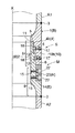
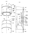
まず、第1の実施例について説明する。図1〜図5において、A1は上柱状体となる鋼管柱状体、A2は下柱状体となる鋼管柱状体である。上柱状体A1には、下柱状体A2と結合される下端に雌形の筒部1(柱状体接続部の一例)が溶接3により下方に突出して設けられ、また、下柱状体A2には、上柱状体A1と結合される上端に、上記筒部1に突入、嵌合する軸部2(柱状体接続部の一例)が溶接3により上方に突出して設けられている。
First, the first embodiment will be described. 1 to 5, A1 is a steel pipe columnar body that is an upper columnar body, and A2 is a steel pipe columnar body that is a lower columnar body. The upper columnar body A1 is provided with a female cylindrical portion 1 (an example of a columnar body connecting portion) protruding downward by welding 3 at the lower end coupled to the lower columnar body A2, and the lower columnar body A2 includes A shaft portion 2 (an example of a columnar body connecting portion) that enters and fits into the
前記筒部1は、外径が鋼管柱状体(上柱状体、下柱状体)A1,A2の外径と同径とした筒状をなしており、その内周は後述する軸部2が嵌合する垂直な筒部内周面4に形成されているとともに、その筒部内周面4における筒部1の基端側に形成の段部1Dには、周溝5が設けられている。そして、前記筒部内周面4には、上下に間隔をおいて複数の内溝部6が周設されている。また、筒部1の下端には、周方向に間隔をおいて複数の切欠部7(凹部Eの一例)が設けられている。
The
前記軸部2は、外径が鋼管柱状体の外径と同径とした基軸部8に続き、外周が前記筒部1の筒部内周面4と係接する垂直の軸部外周面10に形成した嵌挿部9により形成され、軸部先端部2Sには筒部1の周溝5と嵌合する突条11が設けられている。そして、嵌挿部9外周の軸部外周面10には、筒部1の内溝部6と対応する位置に外溝部12が周設されている。また、基軸部8の上部には、筒部1の筒部先端部1Sと接合する接合凹部13が周設されているとともに、その周方向に間隔をおいて、筒部1の切欠部7と対応する位置に、切欠部7と同じ厚さで上下に所要の深さを有する切欠凹部14(凹部Eの一例)が設けられ、各切欠凹部14の奥壁部には複数のネジ孔15が設けられている。
The
そして、上記の各内溝部6には、筒部1の外周より、周方向に間隔をおいて複数設けられたネジ孔16が連通されているとともに、その内溝部6内には、ネジ孔16に螺合させた、セットボルト17の操作によって、内溝部6内から、嵌挿部9の外溝部12内と内溝溝6内に跨る位置まで進退する円弧キー18(キー部材の一例)が収容されている。この円弧キー18を進退させる構造は、例えば図5に示すように、セットボルト17により行う。セットボルト17は、その基端部にネジ孔16と螺合する右ネジの頭部17aを有し、先端部に円弧キー18に設けた左ネジ(逆ネジ)と螺合する尾部17bを有しており、セットボルト17を正(右)回転させてネジ込めば円弧キー18が前進し、逆(左)回転させれば円弧キー18が後退するようになっている。なお、円弧キー18を進退させる構造はこれに限定されるものではない。
A plurality of screw holes 16 provided at intervals in the circumferential direction from the outer periphery of the
また、20は、上柱状体A1の筒部1と下柱状体A2の軸部2との相対回転を防止するための回転抑止キー(嵌合キー部材Hの一例)で、筒部1の切欠部7と軸部2の切欠凹部14とにわたって嵌合する形状に形成されているとともに、切欠凹部14に設けられたネジ孔15と対応する位置にボルト挿通孔21が設けられている。
上柱状体A1と下柱状体A2とを縦継ぎするには、上柱状体A1をクレーンで吊り上げ、下柱状体A2の直上に運んで吊り降ろし、筒部1の中に軸部2を挿入して行けば、筒部1の周溝5と軸部2の軸部先端部の突条11とが接合し、上柱状体A1と下柱状体A2とが嵌合されることになる。そして、上柱状体A1の回転調整により、筒部1の切欠部7を軸部2の切欠凹部14に合致させる。
In order to longitudinally connect the upper columnar body A1 and the lower columnar body A2, the upper columnar body A1 is lifted by a crane, carried directly above the lower columnar body A2, suspended, and the
その後は、切欠部7と切欠凹部14にわたって回転抑止キー20を嵌め込み、取付ボルト22をネジ孔15にネジ込んで固定する(回り止め機構Mの一例)。それにより上下両柱状体A1,A2は回転不能に結合されることになる。続いて、セットボルト17を螺進させて、内溝部6に収まっている円弧キー18を外溝部12に向けて押し入れてやる(接続機構Sの一例)。それによって、円弧キー18は図5の鎖線で示すように両溝部6,12に跨って係合することになり、両柱状体A1,A2は円弧キー18を介して軸芯X方向への抜き差しが不能に結合されることになる。
Thereafter, the
この円弧キー18を介しての結合では、引張力は両溝部6,12と円弧キー18の側面の側圧応力で一方の筒部1または軸部2から円弧キー18に伝達され、せん断力として円弧キー18の反対側に伝達される。そして、再び内、外溝部6,12と円弧キー18の側面の側圧応力によって他方の筒部1または軸部2に伝達される。また、圧縮力は筒部1と軸部2の管軸に垂直な面で圧縮応力によって伝達される。
In the coupling through the
次に、第2の実施例について説明する。この実施例の柱状体は、先の柱状体に対し、筒部1筒部内周面4と軸部2の軸部外周面10の形状を異にしたもので、筒部1の筒部内周面4が先広がりの円錐面4aに形成され、軸部2の軸部内周面10はその円錐面4aと合致する先細りの円錐面10aに形成されている。そして、内溝部6及び外溝部12は、それら円錐面4a,10aに上下に間隔をおいて複数周設されている。
上記構成だと、ネジ嵌合のもののように、柱状体A1,A2どうしを相対回転させながら徐々に近接させるような手間のかかる作業を必要とせず、柱状体軸芯X方向で隣り合う柱状体A1、A2の筒部1に軸部2を挿入する際に、筒部1の軸芯位置と軸部2の軸芯位置がズレていたとしても、前記円錐面4a,10aどうしを接触させたまま柱状体軸芯X方向に近接移動させるだけの操作で筒部1と軸部2とが同芯状に嵌合されるように案内することができる。
なお、その他の構造及び施工の要領については先の柱状体におけると同様であるから、その説明は省略する。
Next, a second embodiment will be described. The columnar body of this embodiment is different from the previous columnar body in the shape of the
With the above configuration, the columnar bodies adjacent to each other in the axis X direction of the columnar body do not require a laborious work of gradually bringing the columnar bodies A1 and A2 close to each other while rotating relative to each other like a screw fitting. When the
In addition, about the other structure and the point of construction, since it is the same as that of the previous columnar body, the description is abbreviate | omitted.
次に、第3の実施例について説明する。この実施例の柱状体は、筒部1の筒部内周面4の形状が、逐次段階的に先広がりとなる筒部内周面4bに形成され、これに対する軸部2の軸部外周面10の形状が、上記筒部内周面4bに合致する、段階的に先細りとなる軸部外周面10bに形成されている。そして、それら筒部内周面4bと軸部外周面10bには、その垂直面に内溝部6及び外溝部12が周設されている。
上記構成だと、柱状体軸芯X方向に近接移動させるだけの操作で筒部1と軸部2とを嵌合させることができ、その際、筒部内周面部4bと軸部外周面部10bの形状を互いに合致する段部形状に形成してあるから、対応する筒部内周面部4bと軸部外周面部10bとが接当するまでの嵌合操作を抵抗なく行うことができるため嵌め易くなる。
その他の構造及び施工の要領については、上記第1、第2実施例におけると同様であるから、その説明は省略する。
Next, a third embodiment will be described. In the columnar body of this embodiment, the shape of the cylindrical inner
With the above configuration, the
Other structures and construction procedures are the same as those in the first and second embodiments, and the description thereof is omitted.
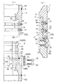
次に、図8(a)、(b)に示す第4実施例について説明する。先の柱状体に対し、Oリング25を設けたことを異にしたもので、鋼管柱状体A1,A2の外径と同径とした筒部1の筒部外周面には、その周方向に間隔をおいて筒部外周面の一部を切欠いた複数の切欠部7(凹部Eの一例)を形成すると共に、筒部内周面4における筒部基端側に形成の段部1Dには周溝5が設けられている。
軸部2には、外径が鋼管柱状体の外径と同径とした基軸部8に続き、外周が筒部1の筒部内周面4と係接する垂直の軸部外周面10に形成した嵌挿部9により形成されると共に、軸部先端部2Sには筒部1の周溝5と嵌合する突条11が設けられている。基軸部8の上部には、筒部1の筒部先端部1Sと接合する接合凹部13が周設されている。接合凹部13にはOリング25が設けられ、筒部1と軸部2とを嵌合させたときに、Oリング25に阻害されること無く、内向き溝部6と外向き溝部12との対向位置を合わすことができ、円弧キー18を係合させる係合操作が確実に行われるように、筒部先端部1Sと接合凹部13との間には、Oリング25の弾性変形を許容すると共に、シールを確実にできる程度の大きさの空間が設定形成されている。また、基軸部8の外周面には、その周方向に間隔をおいて、筒部1の切欠部7と対応する位置に、切欠部7と同じ厚さで上下に所要の深さを有する切欠凹部14が設けられており、切欠部7と切欠凹部14にわたって回転抑止キー20(嵌合キー部材Hの一例)を嵌め込み取付ボルト22をネジ孔15にネジ込んで固定する。
上記構成だと、柱状体A1,A2どうしの軸芯X周りにおける相対回転を防止することができると共に、筒部内周面4と軸部外周面10の接当面、及び、内向き溝部6と外向き溝部12、及び、円弧キー18に対する水の侵入を防止し易くなる。
なお、その他の構造及び施工の要領については先の柱状体におけるものと同様であるから、その説明は省略する。
また、前記Oリング25は、特に必要がなければ設けなくても良い。
Next, a fourth embodiment shown in FIGS. 8A and 8B will be described. It differs from the previous columnar body in that an O-
The
With the above configuration, relative rotation of the columnar bodies A1 and A2 around the axis X can be prevented, the contact surface between the cylindrical inner
In addition, about the other structure and the point of construction, since it is the same as that of the thing in the previous columnar body, the description is abbreviate | omitted.
Further, the O-
次に、図9(a)、(b)に示す第5実施例について説明する。この実施例の柱状体は、先の柱状体に対し、回り止め機構Mの形状を異にしたもので、鋼管柱状体A1,A2の外径と同径とした筒部1の筒部外周面1Gには、その周方向に間隔をおいて筒部外周面1Gの一部を切欠き、対向する柱状体接続部Bの軸部2側に向けて開口する複数の切欠凹部23(凹部Eの一例)を形成すると共に、筒部内周面4における筒部基端側に形成の段部1Dには周溝5が設けられている。 軸部2には、外径が鋼管柱状体の外径と同径とした基軸部8に続き、外周が筒部1の筒部内周面4と係接する垂直の軸部外周面10に形成した嵌挿部9により形成されると共に、軸部先端部2Sには筒部1の周溝5と嵌合する突条11が設けられている。また、基軸部8の上部には、筒部1の筒部先端部1Sと接合する接合凹部13が周設されていると共に、基軸部8における筒部1に対向する端面部1Tの周方向に間隔をおいて筒部1に形成の切欠凹部23に対応する位置に、切欠凹部23に嵌合して係合する形状の係合突起24(嵌合キー部材Hの一例)を形成してある。
そして、筒部1に軸部2を嵌合する際に、切欠凹部23に対向する位置に係合突起24を位置させながら嵌合操作を行うと、軸部先端部2Sに設けた突条11が周溝5に嵌合すると共に、筒部先端部1Sが接合凹部13に嵌合し、同時に切欠凹部23に係合突起24が嵌合係合される。
上記構成だと、切欠凹部23に嵌合する係合突起24の嵌合状態を目視確認できながら操作できると共に、柱状体A1,A2どうしの近接移動による嵌合操作だけで、柱状体A1,A2どうしの軸芯X周りにおける相対回転を防止することができる。
なお、その他の構造及び施工の要領については先の柱状体におけるものと同様であるから、その説明は省略する。
Next, a fifth embodiment shown in FIGS. 9A and 9B will be described. The columnar body of this embodiment is different from the previous columnar body in the shape of the anti-rotation mechanism M, and the outer peripheral surface of the cylindrical portion of the
Then, when fitting the
With the above configuration, the columnar bodies A1 and A2 can be operated while being able to visually confirm the engagement state of the
In addition, about the other structure and the point of construction, since it is the same as that of the thing in the previous columnar body, the description is abbreviate | omitted.
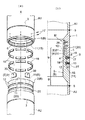
次に、図10(a)、(b)に示す第6実施例について説明する。この実施例の柱状体は、先の柱状体に対し、回り止め機構Mの形状を異にしたもので、筒部1には、筒部先端部1Sに突条11を周設し、突条11の周方向に間隔をおいて、対向する柱状体接続部Bの軸部2側に向けて突設した複数の係合突起26(嵌合キー部材Hの一例)を形成すると共に、筒部内周面4における筒部基端側に形成の段部1Dには周溝5が設けられている。
軸部2には、外径が鋼管柱状体A1,A2の外径と同径とした基軸部8に続き、外周が筒部1の筒部内周面4と係接する垂直の軸部外周面10に形成した嵌挿部9により形成されると共に、軸部先端部2Sには筒部1の周溝5と嵌合する突条11が設けられている。また、基軸部8の上部には、筒部1の筒部先端部1Sと接合する接合凹部13が周設されていると共に、基軸部8における筒部1に対向する端面部2Tの周方向に間隔をおいて筒部1に形成の係合突起26に対応する位置に、係合突起26が嵌入係合する形状のほぞ穴27(凹部Eの一例)を形成してある。
そして、筒部1に軸部2を嵌合する際に、係合突起26に対向する位置にほぞ穴27を位置させながら嵌合操作を行うと、筒部先端部1Sに設けた突条11が周溝5に嵌合すると共に、筒部先端部1Sが接合凹部13に嵌合し、同時にほぞ穴27内に係合突起26が嵌入係合される。
Next, a sixth embodiment shown in FIGS. 10A and 10B will be described. The columnar body of this embodiment is different from the previous columnar body in the shape of the rotation prevention mechanism M. The
The
When the
上記構成だと、例えば、筒部1及び軸部2の外周面に嵌合凸部と嵌合凹部を形成して回り止めを行う構成のものに比して、外周面に形成される接合ラインを少なくできるから、水の侵入を防止し易くできると共に、柱状体A1,A2どうしの近接移動による嵌合操作だけで、柱状体A1,A2どうしの軸芯X周りにおける相対回転を防止することができる。
係合突起26は、上記実施例のごとく突条11と一体に形成されたものの他、図11に示すように、別体に形成した係合突起26をボルト28等で取付けていく構成のものであっても良い。
これだと、ほぞ穴27に係合突起26を嵌合係合させる際に、接触により破損して使えなくなった係合突起26が生じたとしても、その箇所の係合突起26を新しいものに付け換えることができる。
なおその他の構造及び施工の要領については、先の柱状体におけるものと同様であるから、その説明は省略する。
With the above configuration, for example, a joining line formed on the outer peripheral surface as compared with a configuration in which a fitting convex portion and a fitting concave portion are formed on the outer peripheral surface of the
As shown in FIG. 11, the
In this case, when the engaging
In addition, about the other structure and the point of construction, since it is the same as that of the previous columnar body, the description is abbreviate | omitted.
次に、図12(a)、(b)に示す第7実施例について説明する。この実施例の柱状体は、先の柱状体に対し、回り止め機構Mの形状を異にしたもので、筒部1には、筒部先端部1Sに突条11を周設し、筒部内周面4における筒部基端側に形成の段部1Dには周溝5を設けると共に、筒部基端側の内周面の周方向に間隔をおいて、筒部先端側に向けて開口する複数の取付凹部29を形成し、取付凹部29に、筒部基端側に形成の段部1Dから、対向する柱状体接続部Bの軸部2側に向けて係合板材30(嵌合キー部材Hの一例)を突出するように取付けてある。
軸部2には、外径が鋼管柱状体A1,A2の外径と同径とした基軸部8に続き、外周が筒部1の筒部内周面4と係接する垂直の軸部外周面10に形成した嵌挿部9により形成されると共に、基軸部8の上部には、筒部1の筒部先端部1Sの突条11と接合する接合凹部13が周設され、軸部2における筒部1に対向する端面部2Tの周方向に間隔をおいて筒部1に取付けた係合板材30に対向する位置に、係合板材30が嵌入係合する形状の切欠凹部31(凹部Eの一例)を形成してある。
そして、筒部1に軸部2を嵌合する際に、係合板材30に対向する位置に切欠凹部31を位置させながら嵌合操作を行うと、軸部先端部2Sに設けた突条11が周溝5に嵌合すると共に、筒部先端部1Sに設けた突条11が接合凹部13に嵌合し、同時に切欠凹部31内に係合板材30が嵌入係合される。
Next, a seventh embodiment shown in FIGS. 12A and 12B will be described. The columnar body of this embodiment is different from the previous columnar body in the shape of the anti-rotation mechanism M. The
The
When the
上記構成だと、別体に形成した係合板材30を取付けるだけで嵌合キー部材Hを形成することができるから、例えば、削り出し作業で嵌合キー部材Hを形成するものに比して、筒部1内に嵌合キー部材Hを形成する形成作業が容易となると共に、柱状体A1,A2どうしの近接移動による嵌合操作だけで、柱状体A1,A2どうしの軸芯X周りにおける相対回転を防止することができる。
なお、その他の構造及び施工の要領については、先の柱状体におけるものと同様であるから、その説明は省略する。
With the above configuration, the fitting key member H can be formed simply by attaching the
In addition, about the other structure and the point of construction, since it is the same as that of the previous columnar body, the description is abbreviate | omitted.
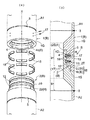
次に、図13(a)、(b)に示す第8の実施例について説明する。この実施例の柱状体は、先の柱状体に対し、回り止め機構Mの形状を異にしたもので、筒部1には、筒部内周面4における筒部基端側に形成の段部1Dに周溝5を設け、筒部内周面4の内径と筒部外周面1Gの外径との間の内径を有した多角形状の内周面により形成される嵌合段部4c(凹部Eの一例)を、対向する柱状体接続部Bの軸部2側に開口するように筒部先端部1Sの内周部に形成すると共に、嵌合段部4cの軸部2側に対向する端面部1Tに突条11を周設してある。
軸部2には、外径が鋼管柱状体A1,A2の外径と同径とした基軸部8と、外周が筒部1の筒部内周面4と係接する垂直の軸部外周面10に形成した嵌挿部9と嵌合軸部2J
(嵌合キー部材Hの一例)とが形成されている。前記嵌合軸部2Jは、基軸部8の上部に、筒部1の筒部先端部1Sの内周部に形成した嵌合段部4cに嵌合係止する外周形状を有した形状に形成されている。
そして、筒部1に軸部2を嵌合する嵌合操作を行うと、筒部基端側に形成の周溝5に軸部先端部2Sに形成の突条11が嵌合すると共に、軸部2の筒部1側に対向する端面部2Tの接合凹部13に筒部端面部1Tの突条11が嵌合し、同時に嵌合段部4c内に嵌合軸部2Jが嵌入係合される。
Next, an eighth embodiment shown in FIGS. 13A and 13B will be described. The columnar body of this embodiment is different from the previous columnar body in the shape of the rotation prevention mechanism M. The
The
(An example of the fitting key member H). The
When the fitting operation for fitting the
上記構成だと、柱状体A1,A2どうしの近接移動による嵌合操作だけで、柱状体A1,A2どうしの軸芯X周りにおける相対回転を防止することができる。
また、嵌合段部4cの内周面の形状及び嵌合軸部2Jの外周面の形状を、点対称の多角形状にしておけば、嵌合段部4cに対する嵌合軸部2Jの対向位置がズレていて嵌合しなかったとしても、嵌合段部4cに嵌合軸部2Jを接当させたまま何れかの柱状体を回転操作することにより両者を嵌合接続することができる。
さらに、嵌合段部4cの内周面の形状及び嵌合軸部2Jの外周面の形状を、非対称の多角形状にしておけば、決まった位置でしか嵌合しないため、柱状体A1,A2どうしの向きを合わせたい場合等に好都合となる。
なお、その他の構造及び施工の要領については、先の柱状体におけるものと同様であるから、その説明は省略する。
With the above configuration, the relative rotation around the axis X between the columnar bodies A1 and A2 can be prevented only by the fitting operation by the close movement of the columnar bodies A1 and A2.
Moreover, if the shape of the inner peripheral surface of the
Further, if the shape of the inner peripheral surface of the
In addition, about the other structure and the point of construction, since it is the same as that of the previous columnar body, the description is abbreviate | omitted.
次に、図14(a)、(b)に示す第9実施例について説明する。この実施例の柱状体は、先の柱状体に対し、回り止め機構Mの形状を異にしたもので、筒部内周面4における筒部基端側に形成の段部1Dには周溝5が設けられると共に、筒部先端部1Sは、筒部基端側の外周径よりも小さくなる外周径の段部形状に形成され、筒部先端部1Sの周方向における複数箇所にボルト挿通孔32(凹部Eの一例)が設けられている。
軸部2には、外径が鋼管柱状体A1,A2の外径と同径とした基軸部8に続き、外周が筒部1の筒部内周面4と係接する垂直の軸部外周面10に形成した嵌挿部9により形成されると共に、軸部先端部2Sには筒部1の周溝5と嵌合する突条11が設けられている。
また、基軸部8の上部には、筒部1の筒部先端部1Sと接合する接合凹部13が周設されていると共に、基軸部8の外周面から接合凹部13を挟んで軸部内周面に至るボルト挿通孔33の複数が、筒部先端部1Sに設けたボルト挿通孔32に対応する位置に形成されている。
そして、筒部1に軸部2を嵌合する際に、筒部先端部1Sに設けたボルト挿通孔32を、基軸部8に形成のボルト挿通孔33(凹部Eの一例)のボルト挿通軸芯に合わせた嵌合操作を行い、ボルト34(嵌合キー部材の一例)を挿通孔32から挿通孔33を介して軸部内周面に向けて螺合させると、軸部先端部2Sに設けた突条11が周溝5に嵌合すると共に、筒部先端部1Sが接合凹部13に嵌合した状態で筒部1と軸部2とを嵌合接続することができる。
Next, a ninth embodiment shown in FIGS. 14A and 14B will be described. The columnar body of this embodiment is different from the previous columnar body in the shape of the rotation prevention mechanism M, and the
The
In addition, a joint
When the
上記構成だと、ボルト34により、柱状体A1,A2どうしの軸芯X周りにおける相対回転を防止することができると共に、柱状体A1,A2どうしの抜け止めを防止する働きをも併せ持つことになる。
なお、その他の構造及び施工の要領については先の柱状体におけるものと同様であるから、その説明は省略する。
With the above configuration, the
In addition, about the other structure and the point of construction, since it is the same as that of the thing in the previous columnar body, the description is abbreviate | omitted.
次に、図15(a)、(b)に示す第10実施例について説明する。この実施例の柱状体は、先の柱状体に対し、回り止め機構Mの形状を異にしたもので、筒部1の筒部内周面4に、内向き溝部6に直交する柱状体軸芯X方向に延びる複数の筒部キー溝35を設けると共に、軸部2の軸部外周面2Gに、外向き溝部12に直交する柱状体軸芯X方向に延びる複数の軸部キー溝36を筒部キー溝35に対向する位置に設け、キー溝35,36の一方にキープレート38を内嵌し、必要に応じてボルト37で止着する。このとき、柱状体接続部Bの径方向におけるキープレート38の厚みは、内嵌させたキー溝から対向するキー溝の深さ分だけ径方向に突出するように形成してある。
そして、筒部1に軸部2を嵌合する際に、キー溝35または36に内嵌しているキープレート38に対向する位置に他方のキー溝35または36を位置させながら嵌合操作を行うと、キープレート38が両キー溝35,36に跨る状態に挿入係合される。
上記構成だと、柱状体A1,A2どうしの近接移動による嵌合操作だけで、柱状体A1,A2どうしの軸芯X方向における相対回転を防止することができる。 なおその他の構造及び施工の要領については、先の柱状体におけるものと同様であるから、その説明は省略する。
Next, a tenth embodiment shown in FIGS. 15A and 15B will be described. The columnar body of this embodiment is different from the previous columnar body in the shape of the rotation prevention mechanism M, and the columnar body axis perpendicular to the
Then, when the
With the above configuration, the relative rotation in the axis X direction between the columnar bodies A1 and A2 can be prevented only by the fitting operation by the close movement of the columnar bodies A1 and A2. In addition, about the other structure and the point of construction, since it is the same as that of the previous columnar body, the description is abbreviate | omitted.
次に、図16(a)、(b)に示す第11実施例について説明する。この実施例の柱状体は、先の柱状体に対し、接続機構Sと回り止め機構Mの形状を異にしたもので、筒部1は、外径が鋼管柱状体A1の外径と同径とした筒状をなしており、その内周は軸部2が嵌合する垂直な筒部内周面4に形成されていると共に、軸部外周面1Gに貫通するボルト挿通孔40(凹部Eの一例)がその周方向に複数形成されている。また、筒部先端部1Sには、突状11が周設されている。
軸部2は、外径が鋼管柱状体A2の外径と同径とした基軸部8に続き、外周が筒部1の筒部内周面4と係接する垂直の軸部外周面10に形成した嵌挿部9により形成され、嵌挿部9には、嵌挿部9を筒部内周面4内に嵌合させたときに、筒部1に形成したボルト挿通孔40に対向する位置にボルト挿通孔41(凹部Eの一例)が形成されている。また、軸部先端部2Sには筒部1の周溝5に嵌合する突条11が設けられていると共に、基軸部8の上部には、筒部1の筒部先端部1Sに形成の突条11と接合する接合凹部13が周設されている。
そして、筒部1に軸部2を嵌合する際に、筒部1に設けたボルト挿通孔40を、嵌挿部9に形成のボルト挿通孔41のボルト挿通軸芯に合わせた嵌合操作を行い、ボルト42
(嵌合キー部材Hの一例)を両挿通孔40,41に跨る状態に螺合接続させると、軸部先端部2Sに設けた突条11が周溝5に嵌合すると共に、筒部先端部1Sに形成の突条11が接合凹部13に嵌合した状態で筒部1と軸部2とを嵌合接続することができる。
上記構成だと、ボルト42の締め付け操作により、柱状体A1,A2どうしの軸芯X周りにおける相対回転を防止(回り止め機構Mの一例)することができると共に、隣接する柱状体どうしを互いに抜け止め状態に接続(接続機構Sの一例)することができる。
Next, an eleventh embodiment shown in FIGS. 16A and 16B will be described. The columnar body of this embodiment is different from the previous columnar body in the shapes of the connection mechanism S and the rotation prevention mechanism M, and the
The
Then, when fitting the
When (an example of the fitting key member H) is screwed and connected so as to straddle both the insertion holes 40 and 41, the
With the above-described configuration, the
〔別実施形態〕
以下に他の実施形態を説明する。
〈1〉柱状体接続機構に用いるキー部材は、先の実施形態で説明した円弧キーに限るものではなく、例えば、C形状の弾性リングキーを、内向き溝部もしくは外向き溝部内に収容しておき、筒部と軸部との嵌合操作に伴って、内向き溝部と外向き溝部内に跨る状態に嵌入する構成であっても良い。
これだと、筒部に対する軸部の嵌合操作だけで隣接する柱状体どうしを互いに抜け止め状態に接続することができる。
〈2〉上記実施形態で鋼管柱状体について説明したが、本発明の適用は鋼管柱状体に限るものではなく、例えば、鋼管矢板等の鋼管を用いたものの他、コンクリート柱状体、合成柱状体等のように他の材質を用いて形成された柱状体においても、本件の構成のごとく形成した柱状体接続部を設けることが可能であるならば適用可能となる。
[Another embodiment]
Other embodiments will be described below.
<1> The key member used for the columnar body connection mechanism is not limited to the arc key described in the previous embodiment. For example, a C-shaped elastic ring key is accommodated in the inward groove portion or the outward groove portion. Alternatively, it may be configured to be fitted in a state straddling the inward groove portion and the outward groove portion in accordance with the fitting operation between the cylindrical portion and the shaft portion.
In this case, the adjacent columnar bodies can be connected to each other in a retaining state only by the fitting operation of the shaft portion with respect to the cylindrical portion.
<2> Although the steel pipe columnar body has been described in the above embodiment, the application of the present invention is not limited to the steel pipe columnar body. For example, in addition to those using a steel pipe such as a steel pipe sheet pile, a concrete columnar body, a synthetic columnar body, etc. Thus, the columnar body formed using other materials can be applied if the columnar body connecting portion formed as in the configuration of the present invention can be provided.
1 筒部(接続部)
1S 筒部先端部
2 軸部(接続部)
2T 端面部
2J 嵌合軸部
4c 嵌合段部
8 基軸部
13 接合凹部
33 嵌合キー部材
A1 柱状体
A2 柱状体
E 凹部
H 嵌合キー部材
M 回り止め機構
X 柱状体軸芯
1 Tube (connection)
Claims (9)
前記柱状体の両端部に設けた両接続部の一方を筒部に形成し、他方を前記筒部に内嵌可能な軸部に形成して、隣接する接続部どうしが嵌合可能に形成し、
前記軸部は、隣り合う柱状体の前記筒部と前記軸部とを互いに嵌合した状態で前記筒部に軸芯方向から対向する端面部を備えた基軸部を有し、
嵌合した柱状体どうしの軸芯周りにおける相対回転を防止する回り止め機構を備え、
前記回り止め機構は、前記筒部及び前記基軸部の外周面よりも内側に備え、
前記回り止め機構は、前記筒部と前記軸部との内の何れか一方に、かつ、前記筒部及び前記基軸部の外周面よりも内側に軸芯方向の一端側に向けて開口する凹部を形成し、
隣り合う柱状体の前記筒部と前記軸部とを軸芯方向から互いに嵌合させる操作に伴ってのみ前記凹部に嵌合する嵌合キー部材を他方に設けて構成してある柱状体。 Each columnar body is provided with a connection portion for an adjacent columnar body, and the columnar body is configured such that the connection portions of the columnar bodies adjacent to each other in the axial direction of the columnar body are freely connectable,
One of the connecting portions provided at both ends of the columnar body is formed in a cylindrical portion, and the other is formed in a shaft portion that can be fitted into the cylindrical portion, so that adjacent connecting portions can be fitted together. ,
The shaft portion has a base shaft portion including an end surface portion facing the tube portion from the axial direction in a state where the tube portion and the shaft portion of adjacent columnar bodies are fitted to each other.
Provided with a detent mechanism that prevents relative rotation around the axis of the fitted columnar bodies,
The rotation prevention mechanism is provided on the inner side of the outer peripheral surface of the cylindrical portion and the base shaft portion ,
The rotation preventing mechanism is a recess that opens in one of the tube portion and the shaft portion and toward the one end side in the axial direction inside the outer peripheral surface of the tube portion and the base shaft portion. Form the
A columnar body in which a fitting key member that fits into the recess is provided on the other side only in accordance with an operation of fitting the cylindrical portion and the shaft portion of adjacent columnar bodies together from the axial direction .
前記凹部を、前記筒部と前記軸部との内の何れか一方の内周面側に当該筒部又は軸部の端面に亘って開口するように設け、
前記凹部に軸芯方向から嵌合する前記嵌合キー部材を他方の内周面側に設けてある請求項1記載の柱状体。 The shaft portion is formed in a cylindrical shaft shape,
The concave portion is provided on the inner peripheral surface side of either the cylindrical portion or the shaft portion so as to open across the end surface of the cylindrical portion or the shaft portion,
Columnar body according to claim 1, wherein is provided the mating key member to be fitted from the axial direction in the recess on the other of the inner peripheral surface side.
前記凹部に軸芯方向から嵌合する前記嵌合キー部材を、前記筒部の内周面側と前記軸部の外周面側との残りの他方に設けてある請求項1記載の柱状体。 2. The columnar body according to claim 1, wherein the fitting key member fitted into the concave portion from the axial direction is provided on the other side of the inner peripheral surface side of the cylindrical portion and the outer peripheral surface side of the shaft portion.
前記柱状体の両端部に設けた両接続部の一方を筒部に形成し、他方を前記筒部に内嵌可能な軸部に形成して、隣接する接続部どうしが嵌合可能に形成し、
前記軸部は、隣り合う柱状体の前記筒部と前記軸部とを互いに嵌合した状態で前記筒部に軸芯方向から対向する端面部を備えた基軸部を有し、
嵌合した柱状体どうしの軸芯周りにおける相対回転を防止する回り止め機構を備え、
前記回り止め機構は、前記筒部及び前記基軸部の外周面よりも内側に備え、
前記回り止め機構は、前記筒部の内周面により形成される嵌合段部と、前記軸部の外周面により形成され、かつ、前記嵌合段部に相対回転不能に内嵌される嵌合軸部とを設けて構成してある柱状体。 Each columnar body is provided with a connection portion for an adjacent columnar body, and the columnar body is configured such that the connection portions of the columnar bodies adjacent to each other in the axial direction of the columnar body are freely connectable,
One of the connecting portions provided at both ends of the columnar body is formed in a cylindrical portion, and the other is formed in a shaft portion that can be fitted into the cylindrical portion, so that adjacent connecting portions can be fitted together. ,
The shaft portion has a base shaft portion including an end surface portion facing the tube portion from the axial direction in a state where the tube portion and the shaft portion of adjacent columnar bodies are fitted to each other.
Provided with a detent mechanism that prevents relative rotation around the axis of the fitted columnar bodies,
The rotation prevention mechanism is provided on the inner side of the outer peripheral surface of the cylindrical portion and the base shaft portion,
The anti-rotation mechanism is formed by a fitting step portion formed by an inner peripheral surface of the cylindrical portion and an outer peripheral surface of the shaft portion, and is fitted into the fitting step portion so as not to be relatively rotatable. configured Thea Ru pillar-shaped body provided the focus shaft portion.
前記柱状体の両端部に設けた両接続部の一方を筒部に形成し、他方を前記筒部に内嵌可能な軸部に形成して、隣接する接続部どうしが嵌合可能に形成し、
前記軸部は、隣り合う柱状体の前記筒部と前記軸部とを互いに嵌合した状態で前記筒部に軸芯方向から対向させる端面部を備えた基軸部を有し、
前記端面部には、隣り合う柱状体の前記筒部と前記軸部とを互いに嵌合した状態で環状の筒部先端部を嵌合させる周溝状の接合凹部が設けられており、
嵌合した柱状体どうしの軸芯周りにおける相対回転を防止する回り止め機構を備え、
前記回り止め機構は、隣り合う柱状体の前記筒部と前記軸部とを互いに嵌合した状態で前記基軸部と前記筒部先端部とに亘って一連に連通可能な凹部と、前記基軸部の外周側から前記凹部に挿通されて、挿通方向先端部が前記基軸部に固定される嵌合キー部材とを設けて構成してある柱状体。 Each columnar body is provided with a connection portion for an adjacent columnar body, and the columnar body is configured such that the connection portions of the columnar bodies adjacent to each other in the axial direction of the columnar body are freely connectable,
One of the connecting portions provided at both ends of the columnar body is formed in a cylindrical portion, and the other is formed in a shaft portion that can be fitted into the cylindrical portion, so that adjacent connecting portions can be fitted together. ,
The shaft portion has a base shaft portion including an end surface portion facing the tube portion from the axial direction in a state where the tube portion and the shaft portion of adjacent columnar bodies are fitted to each other.
The end surface portion is provided with a circumferential groove-like joining recess for fitting the annular cylindrical tip end portion in a state where the cylindrical portion and the shaft portion of adjacent columnar bodies are fitted to each other,
Provided with a detent mechanism that prevents relative rotation around the axis of the fitted columnar bodies,
The rotation preventing mechanism includes a recess capable of communicating in series between the base shaft portion and the tip end portion of the tube portion in a state where the cylindrical portion and the shaft portion of adjacent columnar bodies are fitted to each other, and the base shaft portion A columnar body that is configured to be provided with a fitting key member that is inserted from the outer peripheral side into the concave portion and whose distal end portion in the insertion direction is fixed to the base shaft portion.
Priority Applications (1)
| Application Number | Priority Date | Filing Date | Title |
|---|---|---|---|
| JP2009288116A JP5133334B2 (en) | 1999-03-05 | 2009-12-18 | Columnar |
Applications Claiming Priority (3)
| Application Number | Priority Date | Filing Date | Title |
|---|---|---|---|
| JP5802099 | 1999-03-05 | ||
| JP1999058020 | 1999-03-05 | ||
| JP2009288116A JP5133334B2 (en) | 1999-03-05 | 2009-12-18 | Columnar |
Related Parent Applications (1)
| Application Number | Title | Priority Date | Filing Date |
|---|---|---|---|
| JP2004112333A Division JP4638686B2 (en) | 1999-03-05 | 2004-04-06 | Columnar |
Publications (2)
| Publication Number | Publication Date |
|---|---|
| JP2010059789A JP2010059789A (en) | 2010-03-18 |
| JP5133334B2 true JP5133334B2 (en) | 2013-01-30 |
Family
ID=42186867
Family Applications (1)
| Application Number | Title | Priority Date | Filing Date |
|---|---|---|---|
| JP2009288116A Expired - Lifetime JP5133334B2 (en) | 1999-03-05 | 2009-12-18 | Columnar |
Country Status (1)
| Country | Link |
|---|---|
| JP (1) | JP5133334B2 (en) |
Families Citing this family (2)
| Publication number | Priority date | Publication date | Assignee | Title |
|---|---|---|---|---|
| JP5623923B2 (en) * | 2011-01-24 | 2014-11-12 | 株式会社クボタ | Steel pipe joint structure |
| JP5619650B2 (en) * | 2011-02-18 | 2014-11-05 | 株式会社クボタ | Columnar joint structure and method of cleaning the joint |
Family Cites Families (1)
| Publication number | Priority date | Publication date | Assignee | Title |
|---|---|---|---|---|
| JPH09137447A (en) * | 1995-11-14 | 1997-05-27 | Kubota Corp | Joint construction of pile |
-
2009
- 2009-12-18 JP JP2009288116A patent/JP5133334B2/en not_active Expired - Lifetime
Also Published As
| Publication number | Publication date |
|---|---|
| JP2010059789A (en) | 2010-03-18 |
Similar Documents
| Publication | Publication Date | Title |
|---|---|---|
| JP3329781B2 (en) | Pillar | |
| JP6579945B2 (en) | Steel pipe pile | |
| JP4276715B2 (en) | Pipe joint structure | |
| JP5133334B2 (en) | Columnar | |
| JP5140114B2 (en) | Joining method of ready-made piles, Joined hardware of ready-made piles | |
| JP4638686B2 (en) | Columnar | |
| JP3679964B2 (en) | Columnar | |
| JP4474430B2 (en) | Pile joint structure | |
| JP3776055B2 (en) | Columnar | |
| JP6875681B2 (en) | Steel pipe fitting equipment | |
| JP4274875B2 (en) | Columnar | |
| JP2004211548A5 (en) | ||
| JP3753360B2 (en) | Steel pipe pile cascade | |
| JP4461153B2 (en) | Pile joint structure | |
| JP4609627B2 (en) | Joining method of ready-made piles, Joined hardware of ready-made piles | |
| JPH09137447A (en) | Joint construction of pile | |
| JP2004197397A (en) | Longitudinal joining device for columnar body | |
| JP3753361B2 (en) | Steel pipe pile cascade | |
| JP4424236B2 (en) | Steel pipe sheet pile joint structure and steel pipe sheet pile construction method | |
| JP2013209857A (en) | Joint structure of steel pipe pile and pile head as well as method for constructing concrete foundation using the joint structure | |
| JP5006950B2 (en) | Columnar | |
| JP2000064791A (en) | Joint structure by male-female metal fitting and segment using the same | |
| JP3590364B2 (en) | Connector for steel pipe pile | |
| JP4632723B2 (en) | Columnar | |
| JP2006188889A (en) | Joint structure of pile |
Legal Events
| Date | Code | Title | Description |
|---|---|---|---|
| A521 | Written amendment |
Free format text: JAPANESE INTERMEDIATE CODE: A523 Effective date: 20091228 |
|
| A621 | Written request for application examination |
Free format text: JAPANESE INTERMEDIATE CODE: A621 Effective date: 20091228 |
|
| A131 | Notification of reasons for refusal |
Free format text: JAPANESE INTERMEDIATE CODE: A131 Effective date: 20120301 |
|
| A521 | Written amendment |
Free format text: JAPANESE INTERMEDIATE CODE: A523 Effective date: 20120426 |
|
| TRDD | Decision of grant or rejection written | ||
| A01 | Written decision to grant a patent or to grant a registration (utility model) |
Free format text: JAPANESE INTERMEDIATE CODE: A01 Effective date: 20121101 |
|
| A01 | Written decision to grant a patent or to grant a registration (utility model) |
Free format text: JAPANESE INTERMEDIATE CODE: A01 |
|
| A61 | First payment of annual fees (during grant procedure) |
Free format text: JAPANESE INTERMEDIATE CODE: A61 Effective date: 20121107 |
|
| FPAY | Renewal fee payment (event date is renewal date of database) |
Free format text: PAYMENT UNTIL: 20151116 Year of fee payment: 3 |
|
| R150 | Certificate of patent or registration of utility model |
Free format text: JAPANESE INTERMEDIATE CODE: R150 Ref document number: 5133334 Country of ref document: JP Free format text: JAPANESE INTERMEDIATE CODE: R150 |
|
| EXPY | Cancellation because of completion of term |