JP6241971B2 - ガス放電装置とそれを使用した平面光源およびそれらの駆動方法 - Google Patents
ガス放電装置とそれを使用した平面光源およびそれらの駆動方法 Download PDFInfo
- Publication number
- JP6241971B2 JP6241971B2 JP2016573332A JP2016573332A JP6241971B2 JP 6241971 B2 JP6241971 B2 JP 6241971B2 JP 2016573332 A JP2016573332 A JP 2016573332A JP 2016573332 A JP2016573332 A JP 2016573332A JP 6241971 B2 JP6241971 B2 JP 6241971B2
- Authority
- JP
- Japan
- Prior art keywords
- discharge
- gas discharge
- electrode
- tube
- trigger
- Prior art date
- Legal status (The legal status is an assumption and is not a legal conclusion. Google has not performed a legal analysis and makes no representation as to the accuracy of the status listed.)
- Active
Links
Images
Classifications
-
- H—ELECTRICITY
- H01—ELECTRIC ELEMENTS
- H01J—ELECTRIC DISCHARGE TUBES OR DISCHARGE LAMPS
- H01J65/00—Lamps without any electrode inside the vessel; Lamps with at least one main electrode outside the vessel
-
- H—ELECTRICITY
- H01—ELECTRIC ELEMENTS
- H01J—ELECTRIC DISCHARGE TUBES OR DISCHARGE LAMPS
- H01J61/00—Gas-discharge or vapour-discharge lamps
- H01J61/02—Details
- H01J61/04—Electrodes; Screens; Shields
- H01J61/06—Main electrodes
-
- H—ELECTRICITY
- H01—ELECTRIC ELEMENTS
- H01J—ELECTRIC DISCHARGE TUBES OR DISCHARGE LAMPS
- H01J11/00—Gas-filled discharge tubes with alternating current induction of the discharge, e.g. alternating current plasma display panels [AC-PDP]; Gas-filled discharge tubes without any main electrode inside the vessel; Gas-filled discharge tubes with at least one main electrode outside the vessel
- H01J11/10—AC-PDPs with at least one main electrode being out of contact with the plasma
- H01J11/18—AC-PDPs with at least one main electrode being out of contact with the plasma containing a plurality of independent closed structures for containing the gas, e.g. plasma tube array [PTA] display panels
-
- H—ELECTRICITY
- H01—ELECTRIC ELEMENTS
- H01J—ELECTRIC DISCHARGE TUBES OR DISCHARGE LAMPS
- H01J61/00—Gas-discharge or vapour-discharge lamps
- H01J61/02—Details
- H01J61/30—Vessels; Containers
- H01J61/302—Vessels; Containers characterised by the material of the vessel
-
- H—ELECTRICITY
- H01—ELECTRIC ELEMENTS
- H01J—ELECTRIC DISCHARGE TUBES OR DISCHARGE LAMPS
- H01J61/00—Gas-discharge or vapour-discharge lamps
- H01J61/02—Details
- H01J61/30—Vessels; Containers
- H01J61/305—Flat vessels or containers
-
- H—ELECTRICITY
- H01—ELECTRIC ELEMENTS
- H01J—ELECTRIC DISCHARGE TUBES OR DISCHARGE LAMPS
- H01J61/00—Gas-discharge or vapour-discharge lamps
- H01J61/02—Details
- H01J61/30—Vessels; Containers
- H01J61/33—Special shape of cross-section, e.g. for producing cool spot
-
- H—ELECTRICITY
- H01—ELECTRIC ELEMENTS
- H01J—ELECTRIC DISCHARGE TUBES OR DISCHARGE LAMPS
- H01J61/00—Gas-discharge or vapour-discharge lamps
- H01J61/02—Details
- H01J61/38—Devices for influencing the colour or wavelength of the light
- H01J61/42—Devices for influencing the colour or wavelength of the light by transforming the wavelength of the light by luminescence
-
- H—ELECTRICITY
- H01—ELECTRIC ELEMENTS
- H01J—ELECTRIC DISCHARGE TUBES OR DISCHARGE LAMPS
- H01J61/00—Gas-discharge or vapour-discharge lamps
- H01J61/02—Details
- H01J61/54—Igniting arrangements, e.g. promoting ionisation for starting
- H01J61/547—Igniting arrangements, e.g. promoting ionisation for starting using an auxiliary electrode outside the vessel
-
- H—ELECTRICITY
- H01—ELECTRIC ELEMENTS
- H01J—ELECTRIC DISCHARGE TUBES OR DISCHARGE LAMPS
- H01J61/00—Gas-discharge or vapour-discharge lamps
- H01J61/92—Lamps with more than one main discharge path
-
- H—ELECTRICITY
- H01—ELECTRIC ELEMENTS
- H01J—ELECTRIC DISCHARGE TUBES OR DISCHARGE LAMPS
- H01J63/00—Cathode-ray or electron-stream lamps
- H01J63/08—Lamps with gas plasma excited by the ray or stream
-
- H—ELECTRICITY
- H01—ELECTRIC ELEMENTS
- H01J—ELECTRIC DISCHARGE TUBES OR DISCHARGE LAMPS
- H01J65/00—Lamps without any electrode inside the vessel; Lamps with at least one main electrode outside the vessel
- H01J65/04—Lamps in which a gas filling is excited to luminesce by an external electromagnetic field or by external corpuscular radiation, e.g. for indicating plasma display panels
- H01J65/042—Lamps in which a gas filling is excited to luminesce by an external electromagnetic field or by external corpuscular radiation, e.g. for indicating plasma display panels by an external electromagnetic field
- H01J65/046—Lamps in which a gas filling is excited to luminesce by an external electromagnetic field or by external corpuscular radiation, e.g. for indicating plasma display panels by an external electromagnetic field the field being produced by using capacitive means around the vessel
-
- H—ELECTRICITY
- H05—ELECTRIC TECHNIQUES NOT OTHERWISE PROVIDED FOR
- H05B—ELECTRIC HEATING; ELECTRIC LIGHT SOURCES NOT OTHERWISE PROVIDED FOR; CIRCUIT ARRANGEMENTS FOR ELECTRIC LIGHT SOURCES, IN GENERAL
- H05B41/00—Circuit arrangements or apparatus for igniting or operating discharge lamps
- H05B41/14—Circuit arrangements
- H05B41/24—Circuit arrangements in which the lamp is fed by high frequency AC, or with separate oscillator frequency
Landscapes
- Physics & Mathematics (AREA)
- Engineering & Computer Science (AREA)
- Plasma & Fusion (AREA)
- Electromagnetism (AREA)
- Vessels And Coating Films For Discharge Lamps (AREA)
- Discharge Lamp (AREA)
Description
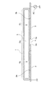
図1は、本発明によるガス放電装置の基本的構成を実施形態1として示す模式的縦断面図である。ネオンとキセノンの混合ガスを封入した細長いガラス管1がデバイスの主体となる外囲器を構成しており、その背面側となる底部外面にガラス管1の長手方向に沿った一対の長電極2及び3が間隙4を挟んで両側に延びるように配置されている。そして、一方の長電極2は接地され、他方の長電極3には正弦波交流電源ACから正弦波交流電圧が印加される。
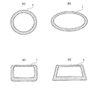
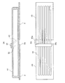
図4(a)及び(b)は、それぞれ本発明によるガス放電装置の実施形態2を示す縦断面図と横断面図である。この実施形態2の基本的構成は図1に示した実施形態1と実質的に同じであるが、図1のガラス管1の背面側底部内面に、ガス放電に伴う紫外線で励起されて発光する蛍光体層7が形成されたガス放電チューブ10を用いる点が、実施形態1とは異なる。なお、ガラス管1の横断面は図4(b)に示すような長方形即ち扁平四辺形であり、長径軸を挟んで対向する平坦面を備えている。ガス放電チューブ10の発光面となる前面側の平坦面には300μm以下の厚みの薄い管壁のほか出射光を遮るものは何もない。
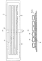
図5(a)及び(b)は、本発明の実施形態3としての平面光源の構成を示す平面図と横断面図である。
電極シート20と電極シート30がトリガ放電部を構成する間隙40(ギャップ寸法Dg)を挟んで近接配置され、その上面に実施形態2で用いた横断面が長方形又は扁平楕円形のガス放電チューブ10が例示的に6本平行に配列されている。
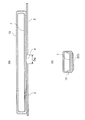
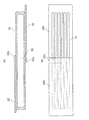
本発明によるガス放電装置の実施形態4を図6(a)、(b)に示す。この実施形態の特徴はトリガ放電部50の構成にある。その他の構成は実施形態3(図5)と同等である。なお、ガス放電チューブ10の内面に設けた紫外発光蛍光体層7は図示を省略している。
図7(a)は、本発明の参考例1としてのガス放電装置を示す縦方向断面図、図7bはその平面図である。この参考例のガス放電装置の特徴は、対となる長電極22と32が1本のガス放電チューブ10の上下対向面に設けられ、近接端部が重なりを持って対向放電セル構造のトリガ放電部52を構成している点にある。ガス放電チューブ10の内面の紫外発光蛍光体層7の図示は省略してある。
この場合も実施形態4と同様に小型電源回路(エレバム社製 S−05584型)で駆動することが可能であった。
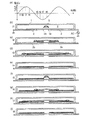
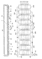
図8(a)、(b)は、それぞれ本発明の参考例2を示す光源用ガス放電装置の縦断面図と平面光源とした場合の裏側から見た裏面図である。この参考例2の特徴は、図4の長電極2,3に対応する複数対の電極セグメント2A,3Aを交互に一列に配置し、ガス放電チューブの長尺化を図った点にある。
参考例2における電極セグメントは、必ずしも図8(a)のようにガス放電チューブ10の底面に一直線上に整列して設ける必要はない。変形例として、ガス放電チューブ10の上面と下面とに電極セグメントを隣接端がオーバーラップする形で交互に設けることができる。この構成によれば、図7を参照して前述した参考例1の対向電極構造のトリガ放電部をガラス放電チューブの長手方向に複数有するガス放電装置を得ることができる。
2,3 長電極
2A,3A 電極セグメント
2a,3a トリガ電極部
2b,3b 主電極部
4 間隙
5 トリガ放電部
6 主ガス放電部
7 蛍光体層
8 支持体
10 ガス放電チューブ
20,30 電極シート
20A 共通セグメント電極
20B 接続導体
20C 端子部
22,32 電極シート
22a トリガ電極部
30A 共通セグメント電極
30B 接続導体
30C 端子部
31 トリガ電極片
32a トリガ電極部
40 間隙
42 接続導体
50 トリガ放電部
52 トリガ放電部
AC 正弦波交流電源
Claims (8)
- 横断面において対向する前面側と平坦な背面側を備え、内部に放電ガスを封入したガラス細管からなる透光性の外囲器と、該外囲器の背面側平坦面の外側に設けた第1及び第2の電極を有し、前記第1及び第2の電極は、前記外囲器の背面側長手方向に沿った一線上において互いに近接した位置でトリガ放電部を構成する間隙を挟んで互いに離間する方向に延びる前記背面側平坦面に対向した電極パターンを有し、
更に、前記外囲器を、発光面となる前面側の厚さが300μm以下の硼珪酸系ガラスの細管で構成し、発光面に対向する背面側の内側に紫外発光蛍光体層を設けたことを特徴とする紫外線発光用のガス放電装置。
- 横断面において対向する前面側と平坦な背面側を備え、内部に放電ガスを封入したガラス細管からなる透光性の外囲器と、該外囲器の背面側平坦面の外側に設けた第1及び第2の電極を有し、前記第1及び第2の電極が、前記外囲器の背面側長手方向に沿った一線上において互いに近接した位置でトリガ放電部を構成する所定寸法の間隙を挟んで当該間隙寸法の少なくとも3倍の長さで両端方向に延び、かつ前記背面側平坦面に対向して有効放電長の全長をカバーする一対の電極パターンを有し、
更に、前記外囲器を、発光面となる前面側の厚さが300μm以下の硼珪酸系ガラスの細管で構成し、発光面に対向する背面側の内側に紫外発光蛍光体層を設けたことを特徴とする紫外線発光用のガス放電装置。
- 前記トリガ放電部を構成する間隙を挟んだ第1及び第2の電極の近接端部の一方に他方の近接端部と対向するトリガ電極片をさらに付設してなることを特徴とする請求項1または2に記載の紫外線発光用のガス放電装置。
- 横断面において対向する前面側と平坦な背面側を有し、内部に放電ガスを封入した透光性のガラス細管と、該ガラス細管の背面側平坦面の外側に位置する第1及び第2の電極とを有し、前記第1と第2の電極が、前記ガラス細管の背面側平坦面の長手方向に沿った一線上において互いに近接した位置でトリガ放電部を構成する間隙を挟んで互いに離間する方向に延びる前記背面側平坦面に対向した電極パターンを有するガス放電チューブを単位発光源とし、該単位発光源となるガス放電チューブを複数本平行に配置するとともに、前記各ガス放電チューブの第1と第2の電極対をそれぞれ電気的に共通接続してなり、
更に、前記各ガラス細管を、発光面となる前面側の厚さが300μm以下の硼珪酸系ガラスで構成し、発光面に対向する背面側の内側に紫外発光蛍光体層を設けたことを特徴とする紫外線発光用のガス放電装置。
- 横断面において対向する前面側と平坦な背面側を有し、背面側平坦面の内面に紫外発光蛍光体層を設けるとともに、内部に放電ガスを封入した複数本のガス放電チューブと、該複数本のガス放電チューブを平行に配列してそれぞれの背面側平坦面を共通に支持する絶縁支持体とから成り、
前記絶縁支持体は、前記各放電チューブの背面側平坦面に共通に対向する第1及び第2の電極を備え、該第1と第2の電極は、各ガス放電チューブの長手方向に対して互いに近接した位置でトリガ放電部を構成する間隙を挟んで互いに離間する方向に延びる共通の電極パターンを有し、
更に、前記各ガス放電チューブを、発光面となる前面側の厚さが300μm以下の硼珪酸系ガラスの細管で構成したことを特徴とする紫外線発光用の平面光源。
- 横断面において対向する前面側と平坦な背面側を有し、内部に放電ガスを封入した複数本のガス放電チューブと、該複数本のガス放電チューブを平行に配列してそれぞれの背面側平坦面を共通に支持する絶縁支持体とから成り、
前記絶縁支持体は、前記各放電チューブの背面側平坦面に共通に対向する第1及び第2の電極を備え、前記第1と第2の電極は前記絶縁支持体の一面に形成した金属箔からなり、かつ各ガス放電チューブの長手方向に対して互いに近接した位置でトリガ放電部を構成する間隙を挟んで互いに離間する方向に延び、実質的に有効放電領域の全体をカバーする各放電チューブに共通の一対のシートパターンを有し、
更に、前記各ガス放電チューブを、発光面となる前面側の厚さが300μm以下の硼珪酸系ガラスの細管で構成し、発光面に対向する背面側の内側に紫外発光蛍光体層を設けたことを特徴とする紫外線発光用の平面光源。
- 前記第1及び第2の電極間に正弦波交番電源を接続し、前記のトリガ放電部で発生した放電が印加正弦波電圧波形の上昇過程において有効放電領域を定める第1第2電極対の両側延長端部へ拡大するように駆動することを特徴とする請求項1−6のいずれか1項に記載のガス放電装置及び平面光源の駆動方法。
- 前記第1及び第2の電極の一方を接地電位とし、他方の電極にピーク電圧への上昇過程で前記トリガ放電部での放電を開始する正弦波交番電圧を印加することを特徴とする請求項7に記載のガス放電装置及び平面光源の駆動方法。
以上
Applications Claiming Priority (5)
| Application Number | Priority Date | Filing Date | Title |
|---|---|---|---|
| JP2015019141 | 2015-02-03 | ||
| JP2015019141 | 2015-02-03 | ||
| JP2015099146 | 2015-05-14 | ||
| JP2015099146 | 2015-05-14 | ||
| PCT/JP2016/052716 WO2016125708A1 (ja) | 2015-02-03 | 2016-01-29 | ガス放電装置とそれを使用した平面光源およびそれらの駆動方法 |
Publications (2)
| Publication Number | Publication Date |
|---|---|
| JPWO2016125708A1 JPWO2016125708A1 (ja) | 2017-04-27 |
| JP6241971B2 true JP6241971B2 (ja) | 2017-12-06 |
Family
ID=56564054
Family Applications (1)
| Application Number | Title | Priority Date | Filing Date |
|---|---|---|---|
| JP2016573332A Active JP6241971B2 (ja) | 2015-02-03 | 2016-01-29 | ガス放電装置とそれを使用した平面光源およびそれらの駆動方法 |
Country Status (4)
| Country | Link |
|---|---|
| US (1) | US9947526B2 (ja) |
| JP (1) | JP6241971B2 (ja) |
| KR (1) | KR101949001B1 (ja) |
| WO (1) | WO2016125708A1 (ja) |
Families Citing this family (17)
| Publication number | Priority date | Publication date | Assignee | Title |
|---|---|---|---|---|
| KR102331041B1 (ko) * | 2017-03-28 | 2021-11-29 | 삼성전자주식회사 | 3차원 이미지에 관한 데이터를 전송하기 위한 방법 |
| KR102338900B1 (ko) * | 2018-02-13 | 2021-12-13 | 삼성전자주식회사 | 전자 장치 및 그 동작 방법 |
| US11011367B2 (en) | 2018-11-12 | 2021-05-18 | Shikoh Tech Co., Ltd. | Light-emitting tube array-type light source device |
| JP7284991B2 (ja) * | 2018-11-12 | 2023-06-01 | 株式会社紫光技研 | 光源装置及びそれを利用した光源モジュールと流体処理装置 |
| US12429190B2 (en) | 2020-11-24 | 2025-09-30 | Shikoh Tech Co., Ltd. | Ultraviolet radiation apparatus |
| KR102585541B1 (ko) | 2021-05-14 | 2023-10-06 | 유니램 주식회사 | 광 조사 장치 |
| KR102585540B1 (ko) | 2021-05-14 | 2023-10-06 | 유니램 주식회사 | 엑시머 램프 및 이를 포함하는 광 조사 장치 |
| KR20220160433A (ko) | 2021-05-27 | 2022-12-06 | 유니램 주식회사 | 외부 전극형 엑시머 램프 및 이를 포함하는 광 조사 장치 |
| KR20220160420A (ko) | 2021-05-27 | 2022-12-06 | 유니램 주식회사 | 외부 전극형 엑시머 램프 및 이를 포함하는 광 조사 장치 |
| KR20220160435A (ko) | 2021-05-27 | 2022-12-06 | 유니램 주식회사 | 필터 일체형 엑시머 램프 |
| KR102585543B1 (ko) | 2021-06-07 | 2023-10-06 | 유니램 주식회사 | 광 조사 장치용 엑시머 램프와 케이스, 그리고 이를 포함하는 광 조사 장치 |
| KR102585542B1 (ko) | 2021-06-07 | 2023-10-06 | 유니램 주식회사 | 광 조사 장치 |
| US12106955B2 (en) * | 2021-10-20 | 2024-10-01 | Goodrich Corporation | Excimer lamp electrode geometry |
| WO2023163245A1 (ko) | 2022-02-24 | 2023-08-31 | 엘지전자 주식회사 | 엑시머 램프 및 이를 포함하는 광 조사 장치 |
| KR102790263B1 (ko) | 2023-03-16 | 2025-04-03 | 유니램 주식회사 | 광 조사 장치 |
| KR102840393B1 (ko) | 2023-10-12 | 2025-07-30 | 유니램 주식회사 | 소형 살균 장치 |
| KR20250141359A (ko) | 2024-03-20 | 2025-09-29 | 유니램 주식회사 | 광 조사 장치 |
Family Cites Families (15)
| Publication number | Priority date | Publication date | Assignee | Title |
|---|---|---|---|---|
| JPS5074381A (ja) | 1973-10-31 | 1975-06-19 | ||
| JP3532578B2 (ja) | 1991-05-31 | 2004-05-31 | 三菱電機株式会社 | 放電ランプおよびこれを用いる画像表示装置 |
| JPH11354078A (ja) * | 1998-06-10 | 1999-12-24 | Ushio Inc | 放電ランプ |
| JP2002216704A (ja) * | 2000-11-16 | 2002-08-02 | Nec Lighting Ltd | 希ガス放電灯 |
| JP3781719B2 (ja) | 2002-11-15 | 2006-05-31 | Necライティング株式会社 | 紫外面光源及びその製造方法並びに蛍光トランスイルミネーター |
| TWI261286B (en) * | 2004-08-31 | 2006-09-01 | Mirae Corp | Flat fluorescent lamp for display devices |
| ATE407990T1 (de) | 2005-04-14 | 2008-09-15 | Koninkl Philips Electronics Nv | Vorrichtung zur erzeugung von uvc-strahlung |
| FR2890232A1 (fr) * | 2005-08-23 | 2007-03-02 | Saint Gobain | Lampe plane a decharge coplanaire et utilisations |
| JP2007173090A (ja) * | 2005-12-22 | 2007-07-05 | Ushio Inc | 紫外線光源装置 |
| JP4424394B2 (ja) * | 2007-08-31 | 2010-03-03 | ウシオ電機株式会社 | エキシマランプ |
| JP5644039B2 (ja) * | 2008-08-29 | 2014-12-24 | ウシオ電機株式会社 | 紫外線を放射する蛍光ランプおよびその製造方法 |
| JP2011040271A (ja) | 2009-08-11 | 2011-02-24 | Shinoda Plasma Kk | 平面光源 |
| JP4885286B2 (ja) * | 2010-03-17 | 2012-02-29 | 篠田プラズマ株式会社 | 紫外光照射装置 |
| US8946662B2 (en) * | 2010-09-29 | 2015-02-03 | Ultraviolet Sciences, Inc. | Excimer light source |
| JP2013118070A (ja) * | 2011-12-02 | 2013-06-13 | Shinoda Plasma Kk | 発光管アレイ型表示装置 |
-
2016
- 2016-01-29 WO PCT/JP2016/052716 patent/WO2016125708A1/ja not_active Ceased
- 2016-01-29 KR KR1020167029383A patent/KR101949001B1/ko active Active
- 2016-01-29 JP JP2016573332A patent/JP6241971B2/ja active Active
- 2016-01-29 US US15/308,802 patent/US9947526B2/en active Active
Also Published As
| Publication number | Publication date |
|---|---|
| WO2016125708A1 (ja) | 2016-08-11 |
| KR20160134841A (ko) | 2016-11-23 |
| JPWO2016125708A1 (ja) | 2017-04-27 |
| US9947526B2 (en) | 2018-04-17 |
| KR101949001B1 (ko) | 2019-05-10 |
| US20170186596A1 (en) | 2017-06-29 |
Similar Documents
| Publication | Publication Date | Title |
|---|---|---|
| JP6241971B2 (ja) | ガス放電装置とそれを使用した平面光源およびそれらの駆動方法 | |
| KR100351344B1 (ko) | 전기방사선원및이방사선원을갖춘조사장치 | |
| JP3856473B2 (ja) | インコヒーレント放射源の点灯方法およびこれに適した照明装置 | |
| JP3264938B2 (ja) | バックライト用平形蛍光ランプ及びこの平形蛍光ランプを備えた液晶表示装置 | |
| CN1097292C (zh) | 放电灯及其工作方法 | |
| EP2367198A2 (en) | Ultraviolet light irradiation device | |
| EP3306641B1 (en) | Gas discharge light-emitting device and drive circuit therefor | |
| CN107535040B (zh) | 光源装置的驱动方法及驱动电路和紫外线照射装置 | |
| TWI398191B (zh) | Rare gas fluorescent lamp lighting device | |
| CN1409162A (zh) | 光源装置和使用了该光源装置的液晶显示器 | |
| TWI239550B (en) | Rare gas discharge lamp of flat type for emitting variable light color, luminaire utilizing the lamp and its lighting method for the same | |
| JP6103730B2 (ja) | ガス放電発光装置 | |
| JP4171060B2 (ja) | 照明装置及び液晶表示装置 | |
| JP6485780B2 (ja) | ガス放電発光装置 | |
| CN1423300A (zh) | 光源装置及液晶显示装置 | |
| CN203406268U (zh) | 改良式流明输出增大的荧光平板灯 | |
| JP4185964B1 (ja) | 誘電体バリア放電ランプ点灯装置 | |
| JP7470994B2 (ja) | 紫外線照射装置とその駆動方法 | |
| JPH06163006A (ja) | 蛍光ランプ装置 | |
| JP4081136B2 (ja) | 誘電体バリア放電ランプ | |
| CN101506935A (zh) | 光源装置及液晶显示装置 | |
| TW201101367A (en) | External electrode type of rare gas fluorescent lamp and rare gas fluorescent lamp unit used as backlight | |
| WO2007086453A1 (ja) | 誘電体バリア型放電ランプ、バックライト装置、及び液晶表示装置 | |
| JP2006049236A (ja) | 放電灯装置、光源装置及び液晶表示装置 | |
| JP2004158467A (ja) | 蛍光ランプ装置 |
Legal Events
| Date | Code | Title | Description |
|---|---|---|---|
| A621 | Written request for application examination |
Free format text: JAPANESE INTERMEDIATE CODE: A621 Effective date: 20161124 |
|
| A131 | Notification of reasons for refusal |
Free format text: JAPANESE INTERMEDIATE CODE: A131 Effective date: 20170822 |
|
| A521 | Request for written amendment filed |
Free format text: JAPANESE INTERMEDIATE CODE: A523 Effective date: 20170921 |
|
| A131 | Notification of reasons for refusal |
Free format text: JAPANESE INTERMEDIATE CODE: A131 Effective date: 20171003 |
|
| A521 | Request for written amendment filed |
Free format text: JAPANESE INTERMEDIATE CODE: A523 Effective date: 20171013 |
|
| TRDD | Decision of grant or rejection written | ||
| A01 | Written decision to grant a patent or to grant a registration (utility model) |
Free format text: JAPANESE INTERMEDIATE CODE: A01 Effective date: 20171024 |
|
| A61 | First payment of annual fees (during grant procedure) |
Free format text: JAPANESE INTERMEDIATE CODE: A61 Effective date: 20171102 |
|
| R150 | Certificate of patent or registration of utility model |
Ref document number: 6241971 Country of ref document: JP Free format text: JAPANESE INTERMEDIATE CODE: R150 |
|
| S531 | Written request for registration of change of domicile |
Free format text: JAPANESE INTERMEDIATE CODE: R313531 |
|
| S533 | Written request for registration of change of name |
Free format text: JAPANESE INTERMEDIATE CODE: R313533 |
|
| R350 | Written notification of registration of transfer |
Free format text: JAPANESE INTERMEDIATE CODE: R350 |
|
| R250 | Receipt of annual fees |
Free format text: JAPANESE INTERMEDIATE CODE: R250 |
|
| R250 | Receipt of annual fees |
Free format text: JAPANESE INTERMEDIATE CODE: R250 |
|
| R250 | Receipt of annual fees |
Free format text: JAPANESE INTERMEDIATE CODE: R250 |
|
| R250 | Receipt of annual fees |
Free format text: JAPANESE INTERMEDIATE CODE: R250 |
|
| R250 | Receipt of annual fees |
Free format text: JAPANESE INTERMEDIATE CODE: R250 |
|
| R250 | Receipt of annual fees |
Free format text: JAPANESE INTERMEDIATE CODE: R250 |