JP6119242B2 - Exposure apparatus, exposure method, and device manufacturing method - Google Patents
Exposure apparatus, exposure method, and device manufacturing method Download PDFInfo
- Publication number
- JP6119242B2 JP6119242B2 JP2012285783A JP2012285783A JP6119242B2 JP 6119242 B2 JP6119242 B2 JP 6119242B2 JP 2012285783 A JP2012285783 A JP 2012285783A JP 2012285783 A JP2012285783 A JP 2012285783A JP 6119242 B2 JP6119242 B2 JP 6119242B2
- Authority
- JP
- Japan
- Prior art keywords
- liquid
- substrate
- movable
- exposure
- flow path
- Prior art date
- Legal status (The legal status is an assumption and is not a legal conclusion. Google has not performed a legal analysis and makes no representation as to the accuracy of the status listed.)
- Active
Links
- 238000000034 method Methods 0.000 title claims description 32
- 238000004519 manufacturing process Methods 0.000 title claims description 18
- 239000000758 substrate Substances 0.000 claims description 371
- 239000007788 liquid Substances 0.000 claims description 370
- 238000011084 recovery Methods 0.000 claims description 227
- 230000003287 optical effect Effects 0.000 claims description 214
- 238000007654 immersion Methods 0.000 claims description 172
- 230000007246 mechanism Effects 0.000 claims description 5
- 239000012530 fluid Substances 0.000 description 126
- 238000005259 measurement Methods 0.000 description 36
- 238000010586 diagram Methods 0.000 description 17
- 238000005286 illumination Methods 0.000 description 16
- 230000008569 process Effects 0.000 description 14
- 230000002950 deficient Effects 0.000 description 12
- 238000003860 storage Methods 0.000 description 11
- 230000001133 acceleration Effects 0.000 description 10
- 239000010408 film Substances 0.000 description 10
- 229920003002 synthetic resin Polymers 0.000 description 9
- 239000000057 synthetic resin Substances 0.000 description 9
- 239000000463 material Substances 0.000 description 7
- 229920001343 polytetrafluoroethylene Polymers 0.000 description 6
- 239000004810 polytetrafluoroethylene Substances 0.000 description 6
- 239000004065 semiconductor Substances 0.000 description 6
- 238000012545 processing Methods 0.000 description 5
- 230000008859 change Effects 0.000 description 4
- XLYOFNOQVPJJNP-UHFFFAOYSA-N water Substances O XLYOFNOQVPJJNP-UHFFFAOYSA-N 0.000 description 4
- PXGOKWXKJXAPGV-UHFFFAOYSA-N Fluorine Chemical compound FF PXGOKWXKJXAPGV-UHFFFAOYSA-N 0.000 description 3
- -1 Poly tetrafluoroethylene Polymers 0.000 description 3
- 238000013459 approach Methods 0.000 description 3
- 230000005540 biological transmission Effects 0.000 description 3
- 229910052731 fluorine Inorganic materials 0.000 description 3
- 239000011737 fluorine Substances 0.000 description 3
- 229940058401 polytetrafluoroethylene Drugs 0.000 description 3
- 238000004891 communication Methods 0.000 description 2
- 229920001577 copolymer Polymers 0.000 description 2
- 238000001514 detection method Methods 0.000 description 2
- RTZKZFJDLAIYFH-UHFFFAOYSA-N ether Substances CCOCC RTZKZFJDLAIYFH-UHFFFAOYSA-N 0.000 description 2
- 239000011521 glass Substances 0.000 description 2
- 238000002955 isolation Methods 0.000 description 2
- 239000004973 liquid crystal related substance Substances 0.000 description 2
- 229920002120 photoresistant polymer Polymers 0.000 description 2
- 229920000098 polyolefin Polymers 0.000 description 2
- 230000005855 radiation Effects 0.000 description 2
- 238000007789 sealing Methods 0.000 description 2
- 230000001360 synchronised effect Effects 0.000 description 2
- 239000010409 thin film Substances 0.000 description 2
- VYZAMTAEIAYCRO-UHFFFAOYSA-N Chromium Chemical compound [Cr] VYZAMTAEIAYCRO-UHFFFAOYSA-N 0.000 description 1
- 238000000018 DNA microarray Methods 0.000 description 1
- 239000004721 Polyphenylene oxide Substances 0.000 description 1
- XUIMIQQOPSSXEZ-UHFFFAOYSA-N Silicon Chemical compound [Si] XUIMIQQOPSSXEZ-UHFFFAOYSA-N 0.000 description 1
- 230000002238 attenuated effect Effects 0.000 description 1
- 230000003796 beauty Effects 0.000 description 1
- 238000005452 bending Methods 0.000 description 1
- 239000000919 ceramic Substances 0.000 description 1
- 229910052804 chromium Inorganic materials 0.000 description 1
- 239000011651 chromium Substances 0.000 description 1
- 230000003749 cleanliness Effects 0.000 description 1
- 238000011109 contamination Methods 0.000 description 1
- 238000013461 design Methods 0.000 description 1
- 238000007599 discharging Methods 0.000 description 1
- 238000009826 distribution Methods 0.000 description 1
- 238000010828 elution Methods 0.000 description 1
- 230000009969 flowable effect Effects 0.000 description 1
- 230000006870 function Effects 0.000 description 1
- 238000007689 inspection Methods 0.000 description 1
- 230000001678 irradiating effect Effects 0.000 description 1
- 238000001459 lithography Methods 0.000 description 1
- 239000011159 matrix material Substances 0.000 description 1
- QSHDDOUJBYECFT-UHFFFAOYSA-N mercury Chemical compound [Hg] QSHDDOUJBYECFT-UHFFFAOYSA-N 0.000 description 1
- 229910052753 mercury Inorganic materials 0.000 description 1
- 238000012986 modification Methods 0.000 description 1
- 230000004048 modification Effects 0.000 description 1
- 238000000465 moulding Methods 0.000 description 1
- 239000003921 oil Substances 0.000 description 1
- 238000012858 packaging process Methods 0.000 description 1
- 230000000149 penetrating effect Effects 0.000 description 1
- 238000000206 photolithography Methods 0.000 description 1
- 229920000570 polyether Polymers 0.000 description 1
- 230000002265 prevention Effects 0.000 description 1
- 230000001681 protective effect Effects 0.000 description 1
- 239000010453 quartz Substances 0.000 description 1
- 230000009467 reduction Effects 0.000 description 1
- 229910052710 silicon Inorganic materials 0.000 description 1
- 239000010703 silicon Substances 0.000 description 1
- VYPSYNLAJGMNEJ-UHFFFAOYSA-N silicon dioxide Inorganic materials O=[Si]=O VYPSYNLAJGMNEJ-UHFFFAOYSA-N 0.000 description 1
- 238000009751 slip forming Methods 0.000 description 1
- 239000000126 substance Substances 0.000 description 1
Images


Classifications
-
- G—PHYSICS
- G03—PHOTOGRAPHY; CINEMATOGRAPHY; ANALOGOUS TECHNIQUES USING WAVES OTHER THAN OPTICAL WAVES; ELECTROGRAPHY; HOLOGRAPHY
- G03F—PHOTOMECHANICAL PRODUCTION OF TEXTURED OR PATTERNED SURFACES, e.g. FOR PRINTING, FOR PROCESSING OF SEMICONDUCTOR DEVICES; MATERIALS THEREFOR; ORIGINALS THEREFOR; APPARATUS SPECIALLY ADAPTED THEREFOR
- G03F7/00—Photomechanical, e.g. photolithographic, production of textured or patterned surfaces, e.g. printing surfaces; Materials therefor, e.g. comprising photoresists; Apparatus specially adapted therefor
- G03F7/70—Microphotolithographic exposure; Apparatus therefor
- G03F7/70216—Mask projection systems
- G03F7/70341—Details of immersion lithography aspects, e.g. exposure media or control of immersion liquid supply
Description
本発明は、露光装置、露光方法、及びデバイス製造方法に関する。 The present invention relates to an exposure apparatus, an exposure method, and a device manufacturing method.
フォトリソグラフィ工程で用いられる露光装置において、例えば下記特許文献に開示されているような、液体を介して露光光で基板を露光する液浸露光装置が知られている。 As an exposure apparatus used in a photolithography process, for example, an immersion exposure apparatus that exposes a substrate with exposure light via a liquid as disclosed in the following patent document is known.
露光装置において、振動が発生すると、露光不良が発生する可能性がある。その結果、不良デバイスが発生する可能性がある。 If vibration occurs in the exposure apparatus, exposure failure may occur. As a result, a defective device may occur.
本発明の態様は、露光不良の発生を抑制できる露光装置、及び露光方法を提供することを目的とする。また、本発明の態様は、不良デバイスの発生を抑制できるデバイス製造方法、プログラム、及び記録媒体を提供することを目的とする。 An object of an aspect of the present invention is to provide an exposure apparatus and an exposure method that can suppress the occurrence of exposure failure. Another object of the present invention is to provide a device manufacturing method, a program, and a recording medium that can suppress the occurrence of defective devices.
本発明の第1の態様に従えば、液体を介して露光光で基板を露光する露光装置であって、露光光が射出される射出面を有する光学部材と、露光光の光路の周囲の少なくとも一部に配置され、光学部材の下方で移動可能な物体上に液体の液浸空間を形成可能であり、液浸空間の液体の少なくとも一部を回収可能な回収部及び回収部からの液体が流通可能な第1流路を有する可動部材を含む液浸部材と、可動部材に接続され、第1流路からの液体が流通可能な第2流路を有し、少なくとも一部が変形可能な変形部材と、を備える露光装置が提供される。 According to the first aspect of the present invention, there is provided an exposure apparatus that exposes a substrate with exposure light through a liquid, the optical member having an exit surface from which the exposure light is emitted, and at least around the optical path of the exposure light. A liquid immersion space can be formed on an object that is disposed in part and is movable below the optical member, and the liquid from the recovery section can recover at least part of the liquid in the immersion space. A liquid immersion member including a movable member having a first flow path that can be circulated, and a second flow path that is connected to the movable member and through which the liquid from the first flow path can flow, and at least a part of which can be deformed. An exposure apparatus including a deformable member is provided.
本発明の第2の態様に従えば、液体を介して露光光で基板を露光する露光装置であって、露光光が射出される射出面を有する光学部材と、露光光の光路の周囲の少なくとも一部に配置され、光学部材の下方で移動可能な物体上に液体の液浸空間を形成可能であり、液浸空間の液体の少なくとも一部を回収可能な回収部及び回収部からの液体が流通可能な第1流路を有する可動部材を含む液浸部材と、少なくとも一部が前記可動部材と対向し、第1流路からの液体が流通可能な第2流路を有し、少なくとも一部が可動部材に対して相対移動可能な接続装置と、を備え、第1流路と液体回収装置に通じる第3流路とが第2流路を介して接続される露光装置が提供される。 According to the second aspect of the present invention, there is provided an exposure apparatus that exposes a substrate with exposure light through a liquid, the optical member having an exit surface from which the exposure light is emitted, and at least around the optical path of the exposure light. A liquid immersion space can be formed on an object that is disposed in part and is movable below the optical member, and the liquid from the recovery section can recover at least part of the liquid in the immersion space. A liquid immersion member including a movable member having a first flowable channel, and a second flow channel at least partially facing the movable member and capable of flowing liquid from the first flow channel, and at least one An exposure apparatus is provided in which the first flow path and the third flow path communicating with the liquid recovery apparatus are connected via the second flow path. .
本発明の第3の態様に従えば、第1、第2のいずれか一つの態様の露光装置を用いて基板を露光することと、露光された基板を現像することと、を含むデバイス製造方法が提供される。 According to a third aspect of the present invention, there is provided a device manufacturing method comprising: exposing a substrate using the exposure apparatus according to any one of the first and second aspects; and developing the exposed substrate. Is provided.
本発明の第4の態様に従えば、光学部材の射出面と基板との間の液体を介して露光光で基板を露光する露光方法であって、露光光の光路の周囲の少なくとも一部に配置され、光学部材の下方で移動可能な物体上に液体の液浸空間を形成可能であり、液浸空間の液体の少なくとも一部を回収可能な回収部及び回収部からの液体が流通可能な第1流路を有する可動部材を含む液浸部材を用いて、光学部材の下方で移動可能な基板上に液体の液浸空間を形成することと、液浸空間の液体を介して射出面から射出される露光光で基板を露光することと、基板の露光の少なくとも一部において、可動部材を移動することと、回収部から回収され第1流路を流れる液体を、可動部材に接続され、少なくとも一部が変形可能な変形部材の第2流路を介して回収することと、を含む露光方法が提供される。 According to a fourth aspect of the present invention, there is provided an exposure method for exposing a substrate with exposure light via a liquid between an emission surface of an optical member and the substrate, wherein at least a part of the periphery of the optical path of the exposure light. A liquid immersion space can be formed on an object that is arranged and movable under the optical member, and a liquid that can collect at least part of the liquid in the liquid immersion space and the liquid from the recovery part can flow The liquid immersion member including the movable member having the first flow path is used to form a liquid immersion space on the substrate movable below the optical member, and from the exit surface through the liquid in the liquid immersion space. Exposing the substrate with the emitted exposure light, moving the movable member in at least part of the exposure of the substrate, and connecting the liquid recovered from the recovery unit and flowing through the first flow path to the movable member; At least partly deformable through the second flow path of the deformable member The exposure method comprising the method comprising, a is provided.
本発明の第5の態様に従えば、光学部材の射出面と基板との間の液体を介して露光光で基板を露光する露光方法であって、露光光の光路の周囲の少なくとも一部に配置され、光学部材の下方で移動可能な物体上に液体の液浸空間を形成可能であり、液浸空間の液体の少なくとも一部を回収可能な回収部及び回収部からの液体が流通可能な第1流路を有する可動部材を含む液浸部材を用いて、光学部材の下方で移動可能な基板上に液体の液浸空間を形成することと、液浸空間の液体を介して射出面から射出される露光光で基板を露光することと、基板の露光の少なくとも一部において、可動部材を移動することと、回収部から回収され第1流路を流れる液体を、少なくとも一部が可動部材と対向し、少なくとも一部が可動部材に対して相対移動可能な接続装置の第2流路、及び第2流路を介して第1流路と接続される第3流路を介して液体回収装置で回収することと、を含む露光方法が提供される。 According to a fifth aspect of the present invention, there is provided an exposure method for exposing a substrate with exposure light via a liquid between an emission surface of an optical member and the substrate, wherein at least a part of the periphery of the optical path of the exposure light. A liquid immersion space can be formed on an object that is arranged and movable under the optical member, and a liquid that can collect at least part of the liquid in the liquid immersion space and the liquid from the recovery part can flow The liquid immersion member including the movable member having the first flow path is used to form a liquid immersion space on the substrate movable below the optical member, and from the exit surface through the liquid in the liquid immersion space. Exposing the substrate with the emitted exposure light, moving the movable member in at least part of the exposure of the substrate, and at least part of the liquid recovered from the recovery unit and flowing through the first flow path. And at least part of it moves relative to the movable member A liquid recovery device via a second flow path of the active connection device and a third flow path connected to the first flow path via the second flow path. .
本発明の第6の態様に従えば、第4、第5のいずれか一つの態様の露光方法を用いて基板を露光することと、露光された基板を現像することと、を含むデバイス製造方法が提供される。 According to a sixth aspect of the present invention, there is provided a device manufacturing method comprising: exposing a substrate using the exposure method according to any one of the fourth and fifth aspects; and developing the exposed substrate. Is provided.
本発明の第7の態様に従えば、コンピュータに、光学部材の射出面と基板との間の液体を介して露光光で基板を露光する液浸露光装置の制御を実行させるプログラムであって、露光光の光路の周囲の少なくとも一部に配置され、光学部材の下方で移動可能な物体上に液体の液浸空間を形成可能であり、液浸空間の液体の少なくとも一部を回収可能な回収部及び回収部からの液体が流通可能な第1流路を有する可動部材を含む液浸部材を用いて、光学部材の下方で移動可能な基板上に液体の液浸空間を形成することと、液浸空間の液体を介して射出面から射出される露光光で基板を露光することと、基板の露光の少なくとも一部において、可動部材を移動することと、回収部から回収され第1流路を流れる液体を、可動部材に接続され、少なくとも一部が変形可能な変形部材の第2流路を介して回収することと、を実行させるプログラムが提供される。 According to a seventh aspect of the present invention, there is provided a program for causing a computer to execute control of an immersion exposure apparatus that exposes a substrate with exposure light via a liquid between an emission surface of an optical member and the substrate. A liquid immersion space can be formed on an object which is arranged at least around the optical path of the exposure light and can be moved below the optical member, and at least a part of the liquid in the immersion space can be collected. Forming a liquid immersion space on a substrate movable below the optical member, using a liquid immersion member including a movable member having a first flow path through which liquid from the unit and the recovery unit can flow; Exposing the substrate with exposure light emitted from the exit surface through the liquid in the immersion space, moving the movable member in at least part of the exposure of the substrate, and collecting the first flow path from the collection unit The liquid flowing through the Programs also be executed and that some are recovered via a second channel of the deformable deformable member, is provided.
本発明の第8の態様に従えば、コンピュータに、光学部材の射出面と基板との間の液体を介して露光光で基板を露光する液浸露光装置の制御を実行させるプログラムであって、露光光の光路の周囲の少なくとも一部に配置され、光学部材の下方で移動可能な物体上に液体の液浸空間を形成可能であり、液浸空間の液体の少なくとも一部を回収可能な回収部及び回収部からの液体が流通可能な第1流路を有する可動部材を含む液浸部材を用いて、光学部材の下方で移動可能な基板上に液体の液浸空間を形成することと、液浸空間の液体を介して射出面から射出される露光光で基板を露光することと、基板の露光の少なくとも一部において、可動部材を移動することと、回収部から回収され第1流路を流れる液体を、少なくとも一部が前記可動部材と対向し、少なくとも一部が可動部材に対して相対移動可能な接続装置の第2流路、及び第2流路を介して第1流路と接続される第3流路を介して液体回収装置で回収することと、を実行させるプログラムが提供される。 According to an eighth aspect of the present invention, there is provided a program for causing a computer to execute control of an immersion exposure apparatus that exposes a substrate with exposure light via a liquid between an emission surface of an optical member and the substrate. A liquid immersion space can be formed on an object which is arranged at least around the optical path of the exposure light and can be moved below the optical member, and at least a part of the liquid in the immersion space can be collected. Forming a liquid immersion space on a substrate movable below the optical member, using a liquid immersion member including a movable member having a first flow path through which liquid from the unit and the recovery unit can flow; Exposing the substrate with exposure light emitted from the exit surface through the liquid in the immersion space, moving the movable member in at least part of the exposure of the substrate, and collecting the first flow path from the collection unit At least part of the liquid flowing through the movable part Liquid recovery via a second flow path of the connection device that is opposed to the movable member and is movable relative to the movable member, and a third flow path that is connected to the first flow path via the second flow path. A program is provided for performing recovery with an apparatus.
本発明の第9の態様に従えば、第7、第8のいずれか一つの態様のプログラムを記録したコンピュータ読み取り可能な記録媒体が提供される。 According to the ninth aspect of the present invention, there is provided a computer-readable recording medium recording the program according to any one of the seventh and eighth aspects.
本発明の態様によれば、露光不良の発生を抑制できる。また、本発明の態様によれば、不良デバイスの発生を抑制できる。 According to the aspect of the present invention, it is possible to suppress the occurrence of exposure failure. Moreover, according to the aspect of this invention, generation | occurrence | production of a defective device can be suppressed.
以下、本発明の実施形態について図面を参照しながら説明するが、本発明はこれに限定されない。以下の説明においては、XYZ直交座標系を設定し、このXYZ直交座標系を参照しつつ各部の位置関係について説明する。水平面内の所定方向をX軸方向、水平面内においてX軸方向と直交する方向をY軸方向、X軸方向及びY軸方向のそれぞれと直交する方向(すなわち鉛直方向)をZ軸方向とする。また、X軸、Y軸、及びZ軸まわりの回転(傾斜)方向をそれぞれ、θX、θY、及びθZ方向とする。 Hereinafter, embodiments of the present invention will be described with reference to the drawings, but the present invention is not limited thereto. In the following description, an XYZ orthogonal coordinate system is set, and the positional relationship of each part will be described with reference to this XYZ orthogonal coordinate system. A predetermined direction in the horizontal plane is defined as an X-axis direction, a direction orthogonal to the X-axis direction in the horizontal plane is defined as a Y-axis direction, and a direction orthogonal to each of the X-axis direction and the Y-axis direction (that is, a vertical direction) is defined as a Z-axis direction. Further, the rotation (inclination) directions around the X axis, Y axis, and Z axis are the θX, θY, and θZ directions, respectively.
<第1実施形態>
第1実施形態について説明する。図1は、第1実施形態に係る露光装置EXの一例を示す概略構成図である。本実施形態の露光装置EXは、液体LQを介して露光光ELで基板Pを露光する液浸露光装置である。本実施形態においては、基板Pに照射される露光光ELの光路Kが液体LQで満たされるように液浸空間LSが形成される。液浸空間とは、液体で満たされた部分(空間、領域)をいう。基板Pは、液浸空間LSの液体LQを介して露光光ELで露光される。本実施形態においては、液体LQとして、水(純水)を用いる。
<First Embodiment>
A first embodiment will be described. FIG. 1 is a schematic block diagram that shows an example of an exposure apparatus EX according to the first embodiment. The exposure apparatus EX of the present embodiment is an immersion exposure apparatus that exposes a substrate P with exposure light EL through a liquid LQ. In the present embodiment, the immersion space LS is formed so that the optical path K of the exposure light EL irradiated to the substrate P is filled with the liquid LQ. The immersion space refers to a portion (space, region) filled with liquid. The substrate P is exposed with the exposure light EL through the liquid LQ in the immersion space LS. In the present embodiment, water (pure water) is used as the liquid LQ.
本実施形態の露光装置EXは、例えば米国特許第6897963号、及び欧州特許出願公開第1713113号等に開示されているような、基板ステージと計測ステージとを備えた露光装置である。 The exposure apparatus EX of the present embodiment is an exposure apparatus provided with a substrate stage and a measurement stage as disclosed in, for example, US Pat. No. 6,897,963 and European Patent Application Publication No. 1713113.
図1において、露光装置EXは、マスクMを保持して移動可能なマスクステージ1と、基板Pを保持して移動可能な基板ステージ2と、基板Pを保持せずに、露光光ELを計測する計測部材(計測器)Cを搭載して移動可能な計測ステージ3と、基板ステージ2及び計測ステージ3の位置を計測する計測システム4と、マスクMを露光光ELで照明する照明系ILと、露光光ELで照明されたマスクMのパターンの像を基板Pに投影する投影光学系PLと、液体LQの液浸空間LSを形成する液浸部材5と、露光装置EX全体の動作を制御する制御装置6と、制御装置6に接続され、露光に関する各種の情報を記憶する記憶装置7とを備えている。
In FIG. 1, an exposure apparatus EX measures a mask stage 1 that can move while holding a mask M, a
また、露光装置EXは、投影光学系PL、及び計測システム4を含む各種の計測システムを支持する基準フレーム8Aと、基準フレーム8Aを支持する装置フレーム8Bと、基準フレーム8Aと装置フレーム8Bとの間に配置され、装置フレーム8Bから基準フレーム8Aへの振動の伝達を抑制する防振装置10とを備えている。防振装置10は、ばね装置などを含む。本実施形態において、防振装置10は、気体ばね(例えばエアマウント)を含む。なお、基板Pのアライメントマークを検出する検出システム及び基板Pなどの物体の表面の位置を検出する検出システムの一方又は両方が基準フレーム8Aに支持されてもよい。
The exposure apparatus EX includes a
また、露光装置EXは、露光光ELが進行する空間CSの環境(温度、湿度、圧力、及びクリーン度の少なくとも一つ)を調整するチャンバ装置9を備えている。空間CSには、少なくとも投影光学系PL、液浸部材5、基板ステージ2、及び計測ステージ3が配置される。本実施形態においては、マスクステージ1、及び照明系ILの少なくとも一部も空間CSに配置される。
In addition, the exposure apparatus EX includes a chamber apparatus 9 that adjusts the environment (at least one of temperature, humidity, pressure, and cleanness) of the space CS in which the exposure light EL travels. In the space CS, at least the projection optical system PL, the
マスクMは、基板Pに投影されるデバイスパターンが形成されたレチクルを含む。マスクMは、例えばガラス板等の透明板と、その透明板上にクロム等の遮光材料を用いて形成されたパターンとを有する透過型マスクを含む。なお、マスクMとして、反射型マスクを用いることもできる。 The mask M includes a reticle on which a device pattern projected onto the substrate P is formed. The mask M includes a transmission type mask having a transparent plate such as a glass plate and a pattern formed on the transparent plate using a light shielding material such as chromium. A reflective mask can also be used as the mask M.
基板Pは、デバイスを製造するための基板である。基板Pは、例えば半導体ウエハ等の基材と、その基材上に形成された感光膜とを含む。感光膜は、感光材(フォトレジスト)の膜である。また、基板Pが、感光膜に加えて別の膜を含んでもよい。例えば、基板Pが、反射防止膜を含んでもよいし、感光膜を保護する保護膜(トップコート膜)を含んでもよい。 The substrate P is a substrate for manufacturing a device. The substrate P includes, for example, a base material such as a semiconductor wafer and a photosensitive film formed on the base material. The photosensitive film is a film of a photosensitive material (photoresist). Further, the substrate P may include another film in addition to the photosensitive film. For example, the substrate P may include an antireflection film or a protective film (topcoat film) that protects the photosensitive film.
照明系ILは、照明領域IRに露光光ELを照射する。照明領域IRは、照明系ILから射出される露光光ELが照射可能な位置を含む。照明系ILは、照明領域IRに配置されたマスクMの少なくとも一部を均一な照度分布の露光光ELで照明する。照明系ILから射出される露光光ELとして、例えば水銀ランプから射出される輝線(g線、h線、i線)及びKrFエキシマレーザ光(波長248nm)等の遠紫外光(DUV光)、ArFエキシマレーザ光(波長193nm)、及びF2レーザ光(波長157nm)等の真空紫外光(VUV光)等が用いられる。本実施形態においては、露光光ELとして、紫外光(真空紫外光)であるArFエキシマレーザ光を用いる。 The illumination system IL irradiates the illumination area IR with the exposure light EL. The illumination area IR includes a position where the exposure light EL emitted from the illumination system IL can be irradiated. The illumination system IL illuminates at least a part of the mask M arranged in the illumination region IR with the exposure light EL having a uniform illuminance distribution. As the exposure light EL emitted from the illumination system IL, for example, far ultraviolet light (DUV light) such as bright lines (g line, h line, i line) and KrF excimer laser light (wavelength 248 nm) emitted from a mercury lamp, ArF Excimer laser light (wavelength 193 nm), vacuum ultraviolet light (VUV light) such as F 2 laser light (wavelength 157 nm), or the like is used. In the present embodiment, ArF excimer laser light, which is ultraviolet light (vacuum ultraviolet light), is used as the exposure light EL.
マスクステージ1は、マスクMを保持した状態で移動可能である。マスクステージ1は、例えば米国特許第6452292号に開示されているような平面モータを含む駆動システム11の作動により移動する。本実施形態において、マスクステージ1は、駆動システム11の作動により、X軸、Y軸、Z軸、θX、θY、及びθZ方向の6つの方向に移動可能である。なお、駆動システム11は、平面モータを含まなくてもよい。駆動システム11は、リニアモータを含んでもよい。 The mask stage 1 can move while holding the mask M. The mask stage 1 is moved by the operation of a drive system 11 including a flat motor as disclosed in US Pat. No. 6,452,292, for example. In the present embodiment, the mask stage 1 can be moved in six directions of the X-axis, Y-axis, Z-axis, θX, θY, and θZ directions by the operation of the drive system 11. The drive system 11 may not include a planar motor. The drive system 11 may include a linear motor.
投影光学系PLは、投影領域PRに露光光ELを照射する。投影領域PRは、投影光学系PLから射出される露光光ELが照射可能な位置を含む。投影光学系PLは、投影領域PRに配置された基板Pの少なくとも一部に、マスクMのパターンの像を所定の投影倍率で投影する。本実施形態において、投影光学系PLは、縮小系である。投影光学系PLの投影倍率は、1/4である。なお、投影光学系PLの投影倍率は、1/5、又は1/8等でもよい。なお、投影光学系PLは、等倍系及び拡大系のいずれでもよい。本実施形態において、投影光学系PLの光軸は、Z軸と平行である。投影光学系PLは、反射光学素子を含まない屈折系、屈折光学素子を含まない反射系、反射光学素子と屈折光学素子とを含む反射屈折系のいずれでもよい。投影光学系PLは、倒立像及び正立像のいずれを形成してもよい。 The projection optical system PL irradiates the projection area PR with the exposure light EL. The projection region PR includes a position where the exposure light EL emitted from the projection optical system PL can be irradiated. The projection optical system PL projects an image of the pattern of the mask M at a predetermined projection magnification onto at least a part of the substrate P arranged in the projection region PR. In the present embodiment, the projection optical system PL is a reduction system. The projection magnification of the projection optical system PL is ¼. The projection magnification of the projection optical system PL may be 1/5 or 1/8. Note that the projection optical system PL may be either an equal magnification system or an enlargement system. In the present embodiment, the optical axis of the projection optical system PL is parallel to the Z axis. Projection optical system PL may be any of a refractive system that does not include a reflective optical element, a reflective system that does not include a refractive optical element, or a catadioptric system that includes a reflective optical element and a refractive optical element. The projection optical system PL may form either an inverted image or an erect image.
投影光学系PLは、露光光ELが射出される射出面12を有する終端光学素子13を含む。射出面12は、投影光学系PLの像面に向けて露光光ELを射出する。終端光学素子13は、投影光学系PLの複数の光学素子のうち、投影光学系PLの像面に最も近い光学素子である。投影領域PRは、射出面12から射出される露光光ELが照射可能な位置を含む。本実施形態において、射出面12は、−Z方向を向いている。射出面12から射出される露光光ELは、−Z方向に進行する。射出面12は、XY平面と平行である。なお、−Z方向を向いている射出面12は、凸面でもよいし、凹面でもよい。なお、射出面12は、XY平面に対して傾斜してもよいし、曲面を含んでもよい。本実施形態において、終端光学素子13の光軸は、Z軸と平行である。
The projection optical system PL includes a terminal
終端光学素子13の光軸と平行な方向に関して、射出面12側が−Z側であり、入射面側が+Z側である。投影光学系PLの光軸と平行な方向に関して、投影光学系PLの像面側が−Z側であり、投影光学系PLの物体面側が+Z側である。
With respect to the direction parallel to the optical axis of the last
基板ステージ2は、基板Pを保持した状態で、射出面12からの露光光ELが照射可能な位置(投影領域PR)を含むXY平面内を移動可能である。計測ステージ3は、計測部材(計測器)Cを搭載した状態で、射出面12からの露光光ELが照射可能な位置(投影領域PR)を含むXY平面内を移動可能である。基板ステージ2及び計測ステージ3のそれぞれは、ベース部材14のガイド面14G上を移動可能である。ガイド面14GとXY平面とは実質的に平行である。
The
基板ステージ2は、例えば米国特許出願公開第2007/0177125号、米国特許出願公開第2008/0049209号等に開示されているような、基板Pをリリース可能に保持する第1保持部と、第1保持部の周囲に配置され、カバー部材Tをリリース可能に保持する第2保持部とを有する。第1保持部は、基板Pの表面(上面)とXY平面とが実質的に平行となるように、基板Pを保持する。第1保持部に保持された基板Pの上面と、第2保持部に保持されたカバー部材Tの上面とは、実質的に同一平面内に配置される。Z軸方向に関して、射出面12と第1保持部に保持された基板Pの上面との距離は、射出面12と第2保持部に保持されたカバー部材Tの上面との距離と実質的に等しい。
The
なお、Z軸方向に関して、射出面12と基板Pの上面との距離が射出面12とカバー部材Tの上面との距離と実質的に等しいとは、射出面12と基板Pの上面との距離と射出面12とカバー部材Tの上面との距離との差が、基板Pの露光時における射出面12と基板Pの上面との距離(所謂、ワーキングディスタンス)の例えば10%以内であることを含む。なお、第1保持部に保持された基板Pの上面と、第2保持部に保持されたカバー部材Tの上面とは、同一平面内に配置されなくてもよい。例えば、Z軸方向に関して、基板Pの上面との位置とカバー部材Tの上面の位置とが異なってもよい。例えば、基板Pの上面とカバー部材Tの上面との間に段差があってよい。なお、基板Pの上面に対してカバー部材Tの上面が傾斜してもよいし、カバー部材Tの上面が曲面を含んでもよい。
Note that the distance between the
基板ステージ2及び計測ステージ3は、例えば米国特許第6452292号に開示されているような平面モータを含む駆動システム15の作動により移動する。駆動システム15は、基板ステージ2に配置された可動子2Cと、計測ステージ3に配置された可動子3Cと、ベース部材14に配置された固定子14Mとを有する。基板ステージ2及び計測ステージ3のそれぞれは、駆動システム15の作動により、ガイド面14G上において、X軸、Y軸、Z軸、θX、θY、及びθZ方向の6つの方向に移動可能である。なお、駆動システム15は、平面モータを含まなくてもよい。駆動システム15は、リニアモータを含んでもよい。
The
計測システム4は、干渉計システムを含む。干渉計システムは、基板ステージ2の計測ミラー及び計測ステージ3の計測ミラーに計測光を照射して、その基板ステージ2及び計測ステージ3の位置を計測するユニットを含む。なお、計測システムが、例えば米国特許出願公開第2007/0288121号に開示されているようなエンコーダシステムを含んでもよい。なお、計測システム4が、干渉計システム及びエンコーダシステムのいずれか一方のみを含んでもよい。
The
基板Pの露光処理を実行するとき、あるいは所定の計測処理を実行するとき、制御装置6は、計測システム4の計測結果に基づいて、基板ステージ2(基板P)、及び計測ステージ3(計測部材C)の位置制御を実行する。
When executing the exposure process of the substrate P or when executing a predetermined measurement process, the control device 6 determines the substrate stage 2 (substrate P) and the measurement stage 3 (measurement member) based on the measurement result of the
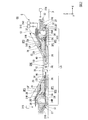
次に、本実施形態に係る液浸部材5について説明する。なお、液浸部材を、ノズル部材、と称してもよい。図2は、XZ平面と平行な液浸部材5の断面図である。図3は、図2の一部を拡大した図である。図4は、液浸部材5の動作の一例を示す図である。図5は、液浸部材5を下側(−Z側)から見た図である。図6及び図7は、液浸部材5の分解斜視図である。
Next, the
液浸部材5は、終端光学素子13の下方で移動可能な物体上に液体LQの液浸空間LSを形成する。
The
終端光学素子13の下方で移動可能な物体は、射出面12と対向する位置を含むXY平面内を移動可能である。その物体は、射出面12と対向可能であり、投影領域PRに配置可能である。その物体は、液浸部材5の下方で移動可能であり、液浸部材5と対向可能である。
An object that can move below the last
本実施形態において、その物体は、基板ステージ2の少なくとも一部(例えば基板ステージ2のカバー部材T)、基板ステージ2(第1保持部)に保持された基板P、及び計測ステージ3の少なくとも一つを含む。
In the present embodiment, the object is at least one of the substrate stage 2 (for example, the cover member T of the substrate stage 2), the substrate P held on the substrate stage 2 (first holding unit), and the
基板Pの露光において、終端光学素子13の射出面12と基板Pとの間の露光光ELの光路Kが液体LQで満たされるように液浸空間LSが形成される。基板Pに露光光ELが照射されているとき、投影領域PRを含む基板Pの表面の一部の領域だけが液体LQで覆われるように液浸空間LSが形成される。
In the exposure of the substrate P, the immersion space LS is formed so that the optical path K of the exposure light EL between the
以下の説明においては、物体が基板Pであることとする。なお、上述のように、物体は、基板ステージ2及び計測ステージ3の少なくとも一方でもよいし、基板P、基板ステージ2、及び計測ステージ3とは別の物体でもよい。
In the following description, it is assumed that the object is the substrate P. As described above, the object may be at least one of the
液浸空間LSは、2つの物体を跨ぐように形成される場合がある。例えば、液浸空間LSは、基板ステージ2のカバー部材Tと基板Pとを跨ぐように形成される場合がある。液浸空間LSは、基板ステージ2と計測ステージ3とを跨ぐように形成される場合がある。
The immersion space LS may be formed so as to straddle two objects. For example, the immersion space LS may be formed so as to straddle the cover member T and the substrate P of the
液浸空間LSは、終端光学素子13の射出面12から射出される露光光ELの光路Kが液体LQで満たされるように形成される。液浸空間LSの少なくとも一部は、終端光学素子13と基板P(物体)との間の空間に形成される。液浸空間LSの少なくとも一部は、液浸部材5と基板P(物体)との間の空間に形成される。
The immersion space LS is formed so that the optical path K of the exposure light EL emitted from the
液浸部材5は、終端光学素子13の周囲の少なくとも一部に配置される第1部材21と、第1部材21の下方において光路Kの周囲の少なくとも一部に配置される第2部材22とを備えている。第2部材22は、第1部材21に対して可動である。第2部材22は、基板P(物体)が対向可能に配置される。
The
第1部材21は、第2部材22よりも基板P(物体)から離れた位置に配置される。第2部材22の少なくとも一部は、第1部材21と基板P(物体)との間に配置される。第2部材22の少なくとも一部は、終端光学素子13と基板P(物体)との間に配置される。
The
第1部材21は、−Z方向を向く下面23と、下面23の周囲の少なくとも一部に配置された流体回収部24とを有する。第2部材22は、+Z方向を向く上面25と、−Z方向を向く下面26と、下面26の周囲の少なくとも一部に配置された流体回収部27とを有する。流体回収部24は、液浸空間LSの液体LQの少なくとも一部を回収する。流体回収部27は、液浸空間LSの液体LQの少なくとも一部を回収する。
The
第1部材21は、終端光学素子13の側面13Fと対向する内側面28と、光路K(終端光学素子13の光軸)に対して外側を向く外側面29とを有する。第2部材22は、外側面29と間隙を介して対向する内側面30を有する。
The
第1部材21の内側面28は、終端光学素子13の側面13Fと間隙を介して対向する。
The
第2部材22は、下面23に対向可能である。第2部材22は、流体回収部24に対向可能である。第2部材22の上面25の少なくとも一部は、下面23と間隙を介して対向する。上面25の少なくとも一部は、射出面12と間隙を介して対向する。
The
基板P(物体)は、下面26に対向可能である。基板P(物体)は、流体回収部27の少なくとも一部に対向可能である。基板Pの上面の少なくとも一部は、下面26と間隙を介して対向する。基板Pの上面の少なくとも一部は、射出面12と間隙を介して対向する。
The substrate P (object) can face the
下面23及び流体回収部24の下面と上面25との間に第1空間SP1が形成される。下面26及び流体回収部27の下面と基板P(物体)の上面との間に第2空間SP2が形成される。側面13Fと内側面28との間に第3空間SP3が形成される。
A first space SP <b> 1 is formed between the
終端光学素子13の側面13Fは、射出面12の周囲に配置される。側面13Fは、露光光ELを射出しない非射出面である。露光光ELは、射出面12を通過し、側面13Fを通過しない。
A
第1部材21の下面23は、液体LQを回収しない。下面23は、非回収部であり、液体LQを回収不可能である。第1部材21の下面23は、第2部材22との間で液体LQを保持可能である。
The
第2部材22の上面25は、液体LQを回収しない。上面25は、非回収部であり、液体LQを回収不可能である。第2部材22の上面25は、第1部材21との間で液体LQを保持可能である。
The
第2部材22の下面26は、液体LQを回収しない。下面26は、非回収部であり、液体LQを回収不可能である。第2部材22の下面26は、基板P(物体)との間で液体LQを保持可能である。
The
内側面28、外側面29、及び内側面30は、液体LQを回収しない。内側面28、外側面29、及び内側面30は、非回収部であり、液体LQを回収不可能である。
The
本実施形態において、下面23は、XY平面と実質的に平行である。上面25も、XY平面と実質的に平行である。下面26も、XY平面と実質的に平行である。すなわち、下面23と上面25とは、実質的に平行である。上面25と下面26とは、実質的に平行である。
In the present embodiment, the
なお、下面23が、XY平面に対して非平行でもよい。下面23は、XY平面に対して傾斜してもよいし、曲面を含んでもよい。
Note that the
なお、上面25が、XY平面に対して非平行でもよい。上面25は、XY平面に対して傾斜してもよいし、曲面を含んでもよい。
Note that the
なお、下面26が、XY平面に対して非平行でもよい。下面26は、XY平面に対して傾斜してもよいし、曲面を含んでもよい。
Note that the
なお、下面23と上面25とは、平行でもよいし、非平行でもよい。上面25と下面26とは、平行でもよいし、非平行でもよい。下面23と下面26とは、平行でもよいし、非平行でもよい。
The
第1部材21は、射出面12から射出された露光光ELが通過可能な開口34を有する。第2部材22は、射出面12から射出された露光光ELが通過可能な開口35を有する。XY平面内における開口34の寸法は、開口35の寸法よりも大きい。本実施形態において、XY平面内における開口35の形状は、長方形状である。開口35は、X軸方向に長い。なお、開口35の形状は、X軸方向に長い楕円形でもよいし、X軸方向に長い多角形でもよい。
The
開口34の内側に終端光学素子13の少なくとも一部が配置される。開口34の下端の周囲に下面23が配置される。開口35の上端の周囲に上面25が配置される。開口35の下端の周囲に下面26が配置される。
At least a part of the last
本実施形態において、光路Kに面する開口35を規定する第2部材22の内面35Uの少なくとも一部は、光路Kに対する放射方向に関して外側に向かって上方に傾斜する。これにより、第2部材22の内面35Uが液浸空間LSに配置されている状態で、第2部材22は円滑に移動可能である。また、第2部材22の内面35Uが液浸空間LSに配置されている状態で第2部材22が移動しても、液浸空間LSの液体LQの圧力が変動することが抑制される。
In the present embodiment, at least a part of the
第1部材21は、終端光学素子13の周囲に配置される。第1部材21は、環状の部材である。第1部材21は、終端光学素子13に接触しないように配置される。第1部材21と終端光学素子13との間に間隙が形成される。第1部材21は、射出面12と対向しない。
The
第2部材22は、射出面12から射出される露光光ELの光路Kの周囲に配置される。第2部材22は、環状の部材である。第2部材22は、第1部材21に接触しないように配置される。第2部材22と第1部材21との間に間隙が形成される。
The
第2部材22は、第1部材21に対して移動可能である。第2部材22は、終端光学素子13に対して移動可能である。第2部材22と第1部材21との相対位置は、変化する。第2部材22と終端光学素子13との相対位置は、変化する。
The
第2部材22は、終端光学素子13の光軸と垂直なXY平面内を移動可能である。第2部材22は、XY平面と実質的に平行に移動可能である。図4に示すように、本実施形態において、第2部材22は、少なくともX軸方向に移動可能である。なお、第2部材22が、X軸方向に加えて、Y軸、Z軸、θX、θY、及びθZの少なくとも一つの方向に移動可能でもよい。
The
本実施形態において、終端光学素子13は、実質的に移動しない。第1部材21も、実質的に移動しない。第1部材21は、終端光学素子13に対して実質的に移動しない。
In the present embodiment, the terminal
第2部材22は、第1部材21の少なくとも一部の下方で移動可能である。第2部材22は、第1部材21と基板P(物体)との間において移動可能である。
The
第2部材22がXY平面内において移動することにより、第1部材21の外側面29と第2部材22の内側面30との間隙の寸法が変化する。換言すれば、第2部材22がXY平面内において移動することによって、外側面29と内側面30との間の空間の大きさが変化する。例えば、図4に示す例では、第2部材22が−X方向に移動することにより、終端光学素子13に対して+X側における外側面29と内側面30との間隙の寸法が小さくなる(外側面29と内側面30との間の空間が小さくなる)。第2部材22が+X方向に移動することにより、終端光学素子13に対して+X側における外側面29と内側面30との間隙の寸法が大きくなる(外側面29と内側面30との間の空間が大きくなる)。本実施形態においては、第1部材21(外側面29)と第2部材22(内側面30)とが接触しないように、第2部材22の移動可能範囲(可動範囲)が定められる。
As the
液浸部材5は、液浸空間LSを形成するための液体LQを供給する液体供給部31を有する。液体供給部31は、第1部材21に配置される。
The
なお、液体供給部31は、第1部材21及び第2部材22の両方に配置されてもよい。なお、液体供給部31は、第1部材21に配置され、第2部材22に配置されなくてもよい。なお、液体供給部31は、第2部材22に配置され、第1部材21に配置されなくてもよい。なお、液体供給部31は、第1部材21及び第2部材22とは異なる部材に配置されてもよい。
The
流体回収部24及び流体回収部27は、露光光ELの光路K(終端光学素子13の光軸)に対する放射方向に関して液体供給部31の外側に配置される。本実施形態において、液体供給部31は、第1部材21の内側面28に配置される開口(液体供給口)を含む。液体供給部31は、側面13Fに対向するように配置される。液体供給部31は、側面13Fと内側面28との間の第3空間SP3に液体LQを供給する。本実施形態において、液体供給部31は、光路K(終端光学素子13)に対して+X側及び−X側のそれぞれに配置される。
The
なお、液体供給部31は、光路K(終端光学素子13)に対してY軸方向に配置されてもよいし、X軸方向及びY軸方向を含む光路K(終端光学素子13)の周囲に複数配置されてもよい。液体供給部31は、一つでもよい。なお、液体供給部31のかわりに、あるいは液体供給部31に加えて、液体LQを供給可能な液体供給部が下面23に設けられてもよい。
The
本実施形態において、液体供給部(液体供給口)31は、第1部材21の内部に形成された供給流路31Rを介して、液体供給装置31Sと接続される。液体供給装置31Sは、クリーンで温度調整された液体LQを液体供給部31に供給可能である。液体供給部31は、液浸空間LSを形成するために、液体供給装置31Sからの液体LQを供給する。
In the present embodiment, the liquid supply part (liquid supply port) 31 is connected to the
下面23の内側のエッジと上面25との間に、開口40が形成される。射出面12と基板P(物体)との間の光路Kを含む光路空間SPKと、下面23と上面25との間の第1空間SP1とは、開口40を介して結ばれる。光路空間SPKは、射出面12と基板P(物体)との間の空間、及び射出面12と上面25との間の空間を含む。開口40は、光路Kに面するように配置される。側面13Fと内側面28との間の第3空間SP3と、第1空間SP1とは、開口40を介して結ばれる。
An
液体供給部31からの液体LQの少なくとも一部は、開口40を介して、下面23と上面25との間の第1空間SP1に供給される。液浸空間LSを形成するために液体供給部31から供給された液体LQの少なくとも一部は、開口34及び開口35を介して、射出面12と対向する基板P(物体)上に供給される。これにより、光路Kが液体LQで満たされる。液体供給部31からの液体LQの少なくとも一部は、下面26と基板P(物体)の上面との間の第2空間SP2に供給される。
At least a part of the liquid LQ from the
Z軸方向に関して、第1空間SP1の寸法は、第2空間SP2の寸法よりも小さい。なお、Z軸方向に関して、第1空間SP1の寸法が、第2空間SP2の寸法と実質的に等しくてもよいし、第2空間SP2の寸法よりも大きくてもよい。 Regarding the Z-axis direction, the dimension of the first space SP1 is smaller than the dimension of the second space SP2. In addition, regarding the Z-axis direction, the dimension of the first space SP1 may be substantially equal to the dimension of the second space SP2, or may be larger than the dimension of the second space SP2.
流体回収部24は、光路K(終端光学素子13の光軸)に対して下面23の外側に配置される。流体回収部24は、下面23の周囲に配置される。流体回収部24は、露光光ELの光路Kの周囲に配置される。なお、流体回収部24は、下面23の周囲の一部に配置されてもよい。例えば、流体回収部24は、下面23の周囲において複数配置されてもよい。流体回収部24は、第1空間SP1に面するように配置される。流体回収部24は、第1空間SP1の液体LQの少なくとも一部を回収する。
The
流体回収部27は、光路K(終端光学素子13の光軸)に対して下面26の外側に配置される。流体回収部27は、開口35の中心に対して下面26の外側に配置される。流体回収部27は、下面26の周囲に配置される。流体回収部27は、露光光ELの光路Kの周囲に配置される。なお、流体回収部27は、下面26の周囲の一部に配置されてもよい。例えば、流体回収部27は、下面26の周囲において複数配置されてもよい。流体回収部27は、第2空間SP2に面するように配置される。流体回収部27は、第2空間SP2の液体LQの少なくとも一部を回収する。
The
流体回収部27は、光路K(終端光学素子13の光軸)に対して第1部材21の外側に配置される。流体回収部27は、光路K(終端光学素子13の光軸)に対して第1空間SP1の外側に配置される。
The
本実施形態においては、上面25側の第1空間SP1及び下面26側の第2空間SP2の一方から他方への液体LQの移動が抑制されている。第1空間SP1と第2空間SP2とは、第2部材22によって仕切られている。第1空間SP1の液体LQは、開口35を介して第2空間SP2に移動できる。第1空間SP1の液体LQは、開口35を介さずに第2空間SP2に移動できない。光路Kに対して開口35よりも外側の第1空間SP1に存在する液体LQは、第2空間SP2に移動できない。第2空間SP2の液体LQは、開口35を介して第1空間SP1に移動できる。第2空間SP2の液体LQは、開口35を介さずに第1空間SP1に移動できない。光路Kに対して開口35よりも外側の第2空間SP2に存在する液体LQは、第1空間SP1に移動できない。すなわち、本実施形態において、液浸部材5は、開口35以外に、第1空間SP1と第2空間SP2とを流体的に接続する流路を有しない。
In the present embodiment, the movement of the liquid LQ from one of the first space SP1 on the
本実施形態において、流体回収部27は、第2空間SP2の液体LQの少なくとも一部を回収し、第1空間SP1の液体LQを回収しない。流体回収部24は、第1空間SP1の液体LQの少なくとも一部を回収し、第2空間SP2の液体LQを回収しない。
In the present embodiment, the
また、光路Kに対して第1空間SP1の外側(外側面29の外側)に移動した液体LQは、内側面30によって、基板P上(第2空間SP2)に移動することが抑制される。
Further, the liquid LQ that has moved to the outside of the first space SP1 (outside of the outer surface 29) with respect to the optical path K is suppressed by the
流体回収部24は、第1部材21の下面23の周囲の少なくとも一部に配置される開口(流体回収口)を含む。流体回収部24は、上面25に対向するように配置される。流体回収部24は、第1部材21の内部に形成された回収流路(空間)24Rを介して、流体回収装置24Cと接続される。流体回収装置24Cは、流体回収部24と真空システムとを接続可能である。流体回収部24は、第1空間SP1の液体LQの少なくとも一部を回収可能である。第1空間SP1の液体LQの少なくとも一部は、流体回収部24を介して回収流路24Rに流入可能である。流体回収部24からの液体LQは、回収流路24Rを流通可能である。
The
本実施形態において、流体回収部24は、多孔部材36を含み、流体回収口は、多孔部材36の孔を含む。本実施形態において、多孔部材36は、メッシュプレートを含む。多孔部材36は、上面25が対向可能な下面と、回収流路24Rに面する上面と、下面と上面とを結ぶ複数の孔とを有する。流体回収部24は、多孔部材36の孔を介して液体LQを回収する。流体回収部24(多孔部材36の孔)から回収された第1空間SP1の液体LQは、回収流路24Rに流入し、その回収流路24Rを流れて、流体回収装置24Cに回収される。
In the present embodiment, the
本実施形態においては、流体回収部24を介して実質的に液体LQのみが回収され、気体GSの回収が制限されている。制御装置6は、第1空間SP1の液体LQが多孔部材36の孔を通過して回収流路24Rに流入し、気体GSは通過しないように、多孔部材36の下面側の圧力(第1空間SP1の圧力)と上面側の圧力(回収流路24Rの圧力)との差を調整する。なお、多孔部材を介して液体のみを回収する技術の一例が、例えば米国特許第7292313号などに開示されている。
In the present embodiment, substantially only the liquid LQ is recovered via the
なお、多孔部材36を介して液体LQ及び気体GSの両方が回収(吸引)されてもよい。なお、第1部材21に多孔部材36が設けられなくてもよい。すなわち、多孔部材を介さずに第1空間SP1の流体(液体LQ及び気体GSの一方又は両方)が回収されてもよい。
Note that both the liquid LQ and the gas GS may be collected (sucked) through the
本実施形態において、流体回収部24の下面は、多孔部材36の下面を含む。流体回収部24の下面は、下面23の周囲に配置される。本実施形態において、流体回収部24の下面は、XY平面と実質的に平行である。本実施形態において、流体回収部24の下面と下面23とは、同一平面内に配置される(面一である)。
In the present embodiment, the lower surface of the
なお、流体回収部24の下面が下面23よりも+Z側に配置されてもよいし、−Z側に配置されてもよい。なお、流体回収部24の下面が下面23に対して傾斜してもよいし、曲面を含んでもよい。
The lower surface of the
なお、第1空間SP1の流体(液体LQ及び気体GSの一方又は両方)を回収するための流体回収部24が、第1空間SP1に面するように第2部材22に配置されてもよい。流体回収部24は、第1部材21及び第2部材22の両方に配置されてもよい。流体回収部24は、第1部材21に配置され、第2部材22に配置されなくてもよい。流体回収部24は、第2部材22に配置され、第1部材21に配置されなくてもよい。
In addition, the
流体回収部27は、第2部材22の下面26の周囲の少なくとも一部に配置される開口(流体回収口)を含む。流体回収部27は、基板P(物体)の上面に対向するように配置される。流体回収部27は、第2部材22の内部に形成された回収流路(空間)27Rを介して、流体回収装置27Cと接続される。流体回収装置27Cは、流体回収部27と真空システムとを接続可能である。流体回収部27は、第2空間SP2の液体LQの少なくとも一部を回収可能である。第2空間SP2の液体LQの少なくとも一部は、流体回収部27を介して回収流路27Rに流入可能である。流体回収部27からの液体LQは、回収流路27Rを流通可能である。
The
本実施形態において、流体回収部27は、多孔部材37を含み、流体回収口は、多孔部材37の孔を含む。本実施形態において、多孔部材37は、メッシュプレートを含む。多孔部材37は、基板P(物体)の上面が対向可能な下面と、回収流路27Rに面する上面と、下面と上面とを結ぶ複数の孔とを有する。流体回収部27は、多孔部材37の孔を介して流体(液体LQ及び気体GSの一方又は両方)を回収する。流体回収部27(多孔部材37の孔)から回収された第2空間SP2の液体LQは、回収流路27Rに流入し、その回収流路27Rを流れて、流体回収装置27Cに回収される。
In the present embodiment, the
回収流路27Rは、光路K(終端光学素子13の光軸)に対して内側面30の外側に配置される。回収流路27Rは、流体回収部27の上方に配置される。第2部材22が移動することにより、第2部材22の流体回収部27及び回収流路27Rが、第1部材21の外側面29の外側で移動する。
The
流体回収部27を介して液体LQとともに気体GSが回収される。なお、多孔部材37を介して液体LQのみが回収され、気体GSの回収が制限されてもよい。なお、第2部材22に多孔部材37が設けられなくてもよい。すなわち、多孔部材を介さずに第2空間SP2の流体(液体LQ及び気体GSの一方又は両方)が回収されてもよい。
The gas GS is recovered together with the liquid LQ via the
本実施形態において、流体回収部27の下面は、多孔部材37の下面を含む。流体回収部27の下面は、下面26の周囲に配置される。本実施形態において、流体回収部27の下面は、XY平面と実質的に平行である。本実施形態において、流体回収部27の下面は、下面26よりも+Z側に配置される。
In the present embodiment, the lower surface of the
なお、流体回収部27の下面と下面26とが同一平面内に配置されてもよい(面一でもよい)。流体回収部27の下面が下面26よりも−Z側に配置されてもよい。流体回収部27の下面が下面26に対して傾斜してもよいし、曲面を含んでもよい。
Note that the lower surface and the
本実施形態においては、液体供給部31からの液体LQの供給動作と並行して、流体回収部27からの液体LQの回収動作が実行されることによって、一方側の終端光学素子13及び液浸部材5と、他方側の基板P(物体)との間に液体LQで液浸空間LSが形成される。
In the present embodiment, the recovery operation of the liquid LQ from the
また、本実施形態においては、液体供給部31からの液体LQの供給動作、及び流体回収部27からの流体の回収動作と並行して、流体回収部24からの流体の回収動作が実行される。
In the present embodiment, the recovery operation of the fluid from the
本実施形態において、液浸空間LSの液体LQの界面LGの一部は、第2部材22と基板P(物体)との間に形成される。液浸空間LSの液体LQの界面LGの一部は、第1部材21と第2部材22との間に形成される。液浸空間LSの液体LQの界面LGの一部は、終端光学素子13と第1部材21との間に形成される。
In the present embodiment, a part of the interface LG of the liquid LQ in the immersion space LS is formed between the
以下の説明において、第1部材21と第2部材22との間に形成される液体LQの界面LGを適宜、第1界面LG1、と称する。第2部材22と基板P(物体)との間に形成される界面LGを適宜、第2界面LG2、と称する。終端光学素子13と第1部材21との間に形成される界面LGを適宜、第3界面LG3、と称する。
In the following description, the interface LG of the liquid LQ formed between the
本実施形態において、第1界面LG1は、流体回収部24の下面と上面25との間に形成される。第2界面LG2は、流体回収部27の下面と基板P(物体)の上面との間に形成される。
In the present embodiment, the first interface LG <b> 1 is formed between the lower surface and the
本実施形態においては、第1界面LG1が流体回収部24の下面と上面25との間に形成され、第1空間SP1の液体LQが流体回収部24の外側の空間(例えば外側面29と内側面30との間の空間)に移動することが抑制されている。外側面29と内側面30との間の空間には液体LQが存在しない。外側面29と内側面30との間の空間は気体空間である。
In the present embodiment, the first interface LG1 is formed between the lower surface and the
外側面29と内側面30との間の空間は、空間CSと接続される。換言すれば、外側面29と内側面30との間の空間は、雰囲気に開放される。空間CSの圧力が大気圧である場合、外側面29と内側面30との間の空間は、大気開放される。そのため、第2部材22は円滑に移動可能である。なお、空間CSの圧力は、大気圧よりも高くてもよいし、低くてもよい。
A space between the
次に、第2部材22の動作の一例について説明する。第2部材22は、基板P(物体)の移動と協調して移動可能である。第2部材22は、基板P(物体)と独立して移動可能である。第2部材22は、基板P(物体)の移動の少なくとも一部と並行して移動可能である。
Next, an example of the operation of the
第2部材22は、基板P(物体)が移動する期間の少なくとも一部と並行して移動されてもよい。第2部材22は、基板P(物体)の移動方向に移動されてもよい。例えば、基板Pが移動される期間の少なくとも一部において、第2部材22は、基板Pの移動方向に移動されてもよい。例えば、基板PがXY平面内における一方向(例えば+X方向)に移動されるとき、第2部材22は、その基板Pの移動と同期して、XY平面内における一方向(+X方向)に移動されてもよい。
The
第2部材22は、液浸空間LSが形成された状態で移動されてもよい。第2部材22は、液浸空間LSの液体LQが接触された状態で移動されてもよい。第2部材22は、第1空間SP1及び第2空間SP2に液体LQが存在する状態で移動されてもよい。第2部材22は、液体供給部31からの液体LQの供給と並行して移動されてもよい。第2部材22は、流体回収部24からの液体LQの回収と並行して移動されてもよい。第2部材22は、流体回収部27からの液体LQの回収と並行して移動されてもよい。第2部材22は、液体供給部31からの液体LQの供給及び流体回収部24(流体回収部27)からの液体LQの回収と並行して移動されてもよい。
The
第2部材22は、射出面12から露光光ELが射出される期間の少なくとも一部において移動されてもよい。
The
第2部材22は、液浸空間LSが形成されている状態で基板P(物体)が移動する期間の少なくとも一部と並行して移動されてもよい。第2部材22は、液浸空間LSが形成されている状態で射出面12から露光光ELが射出される期間の少なくとも一部において移動されてもよい。
The
第2部材22は、第2部材22と基板P(物体)とが対向しないときに移動してもよい。例えば、第2部材22は、その第2部材22の下方に物体が存在しないときに移動してもよい。なお、第2部材22は、第2部材22と基板P(物体)との間の空間に液体LQが存在しないときに移動してもよい。例えば、第2部材22は、液浸空間LSが形成されていないときに移動してもよい。
The
本実施形態において、第2部材22は、例えば基板P(物体)の移動条件に基づいて移動する。制御装置6は、例えば基板P(物体)の移動条件に基づいて、基板P(物体)の移動の少なくとも一部と並行して第2部材22を移動する。制御装置6は、液浸空間LSが形成され続けるように、液体供給部31からの液体LQの供給と流体回収部27及び流体回収部24からの液体LQの回収とを行いながら、第2部材22を移動する。
In the present embodiment, the
本実施形態において、第2部材22は、基板P(物体)との相対移動が小さくなるように移動可能である。第2部材22は、第2部材22と基板P(物体)との相対移動が、終端光学素子13と基板P(物体)との相対移動よりも小さくなるように移動可能である。第2部材22は、第2部材22と基板P(物体)との相対移動が、第1部材21と基板P(物体)との相対移動よりも小さくなるように移動可能である。例えば、第2部材22は、基板P(物体)と同期して移動してもよい。
In this embodiment, the
相対移動は、相対速度、及び相対加速度の少なくとも一方を含む。例えば、第2部材22は、液浸空間LSが形成されている状態で、すなわち、第2空間SP2に液体LQが存在している状態で、基板P(物体)との相対速度が小さくなるように移動してもよい。
The relative movement includes at least one of a relative speed and a relative acceleration. For example, the
また、第2部材22は、液浸空間LSが形成されている状態で、すなわち、第2空間SP2に液体LQが存在している状態で、基板P(物体)との相対加速度が小さくなるように移動してもよい。
Further, the
また、第2部材22は、液浸空間LSが形成されている状態で、すなわち、第2空間SP2に液体LQが存在している状態で、基板P(物体)との相対速度が、第1部材21と基板P(物体)との相対速度よりも小さくなるように移動してもよい。
Further, the
また、第2部材22は、液浸空間LSが形成されている状態で、すなわち、第2空間SP2に液体LQが存在している状態で、基板P(物体)との相対加速度が、第1部材21と基板P(物体)との相対加速度よりも小さくなるように移動してもよい。
Further, the
第2部材22は、例えば基板P(物体)の移動方向に移動可能である。例えば、基板P(物体)が+X方向(または−X方向)に移動するとき、第2部材22は+X方向(または−X方向)に移動可能である。また、基板P(物体)が+X方向に移動しつつ+Y方向(又は−Y方向)に移動するとき、第2部材22は+X方向に移動可能である。また、基板P(物体)が−X方向に移動しつつ+Y方向(又は−Y方向)に移動するとき、第2部材22は−X方向に移動可能である。
The
すなわち、本実施形態においては、基板P(物体)がX軸方向の成分を含むある方向に移動する場合、第2部材22はX軸方向に移動する。例えば、X軸方向の成分を含むある方向への基板P(物体)の移動の少なくとも一部と並行して、第2部材22がX軸方向に移動してもよい。
That is, in the present embodiment, when the substrate P (object) moves in a certain direction including a component in the X-axis direction, the
なお、第2部材22がY軸方向に移動可能でもよい。基板P(物体)がY軸方向の成分を含むある方向に移動する場合、第2部材22がY軸方向に移動してもよい。例えば、Y軸方向の成分を含むある方向への基板P(物体)の移動の少なくとも一部と並行して、基板P(物体)との相対速度差が小さくなるように、第2部材22がY軸方向に移動してもよい。
Note that the
次に、液浸部材5を支持する支持装置50の一例について説明する。図8及び図9は、本実施形態に係る液浸部材5及び支持装置50の一例を示す側面図である。図10及び図11は、本実施形態に係る液浸部材5及び支持装置50の一例を示す平面図である。図8は、−Y側から見た図、図9は、+X側から見た図である。図10は、+Z側から見た図、図11は、−Z側から見た図である。
Next, an example of the
本実施形態において、支持装置50は、第1部材21を支持する第1支持部材51と、第2部材22を支持する第2支持部材52と、第1支持部材51を支持する支持フレーム53と、第2支持部材52を支持する移動フレーム54とを有する。
In the present embodiment, the
第1支持部材51は、第1部材21に接続される。第1部材21は、第1支持部材51に固定される。第1支持部材51は、第1部材21を囲むように配置される。
The
支持フレーム53は、第1支持部材51に接続される。第1支持部材51は、支持フレーム53に固定される。支持フレーム53は、第1支持部材51を介して、第1部材21を支持する。
The
第2支持部材52は、第2部材22に接続される。第2部材22は、第2支持部材52に固定される。本実施形態において、第2支持部材51は、開口35の中心に対して+Y側の第2部材22の一部分に接続される。第2支持部材52は、光路Kに対して第1部材21の外側で第2部材22に接続される。第2支持部材52は、+Z方向を向く上面52Aと、−Z方向を向く下面52Bとを有する。
The
移動フレーム54は、第2支持部材52に接続される。第2支持部材52は、移動フレーム54に固定される。移動フレーム54は、第2支持部材52を介して、第2部材22を支持する。
The moving
本実施形態において、第1部材21と第2部材22とは接触しない。第1支持部材51と第2支持部材52とは接触しない。第1支持部材51の下面51Bと第2支持部材52の上面52Aとは、間隙を介して対向する。
In the present embodiment, the
支持装置50は、第1部材21の振動を抑制する防止装置55を有する。防振装置55は、例えば、第2部材22の移動に伴う第1部材21の振動を抑制する。防振装置55は、制御装置6に制御される。防振装置55の少なくとも一部は、支持フレーム53と装置フレーム8Bとの間に配置される。
The
支持装置50は、第2部材22を移動する駆動装置56を有する。第2部材22は、駆動装置56によって移動される。駆動装置56は、例えばモータを含み、ローレンツ力を使って第2部材22を移動可能である。駆動装置56は、第1部材21に対して第2部材22を移動可能である。駆動装置56は、制御装置6に制御される。駆動装置56の少なくとも一部は、装置フレーム8Bに支持される。
The
移動フレーム54は、第2支持部材52を介して、第2部材22を支持する。本実施形態において、駆動装置56は、移動フレーム54を移動する。駆動装置56によって移動フレーム54が移動されることにより、第2支持部材52が移動する。駆動装置56によって第2支持部材52が移動されることにより、第2部材22が移動する。第2部材22と第2支持部材52とは一緒に移動する。
The moving
支持フレーム53は、装置フレーム8Bに支持される。支持フレーム53は、防振装置55を介して、装置フレーム8Bに支持される。防振装置55は、支持フレーム53及び第1支持部材51を介して、第1部材21を支持する。第1部材21は、第1支持部材51及び支持フレーム53を介して、防振装置55に支持される。装置フレーム8Bは、防振装置55、支持フレーム53、及び第1支持部材51を介して、第1部材21を支持する。
The
移動フレーム54は、装置フレーム8Bに支持される。移動フレーム54は、駆動装置56を介して、装置フレーム8Bに支持される。駆動装置56は、移動フレーム54及び第2支持部材52を介して、第2部材22を支持する。第2部材22は、第2支持部材52及び移動フレーム54を介して、駆動装置56に支持される。装置フレーム8Bは、駆動装置56、移動フレーム54、及び第2支持部材52を介して、第2部材22を支持する。
The moving
本実施形態において、装置フレーム8Bは、投影光学系PL(終端光学素子13)を支持する基準フレーム8A、第1部材21を支持する支持フレーム53(防振装置55)、及び第2部材22を支持する移動フレーム54(駆動装置56)を支持する。
In the present embodiment, the
本実施形態において、駆動装置56は、終端光学素子13の光軸に対して−X側に配置される。本実施形態において、移動フレーム54は、X軸方向に長いロッド部材である。本実施形態において、移動フレーム54の−X側の端部に駆動装置56が接続される。移動フレーム54の+X側の端部に第2支持部材52が接続される。
In the present embodiment, the driving
支持装置50は、第2部材22をガイドするガイド装置57を有する。本実施形態において、ガイド装置57は、第2部材22をX軸方向にガイドする。本実施形態において、ガイド装置57の少なくとも一部は、第1支持部材51(第1部材21)と第2支持部材52(第2部材22)との間に配置される。
The
ガイド装置57によって、第2部材22は、X軸方向にガイドされる。本実施形態において、Y軸、Z軸、θX、θY、及びθZ方向に関する第2部材22の移動は制限される。ガイド装置57は、第1支持部材51の下面51Bと第2支持部材52の上面52Aとの間に気体軸受57Gを有する。ガイド装置57は、所謂、エアガイド機構を含む。気体軸受57Gにより、第2支持部材22(第2部材22)は、第1支持部材21(第1部材21)に非接触で支持される。気体軸受57Gにより、第2支持部材22(第2部材22)は、第1支持部材21(第1部材21)に対して非接触状態でX軸方向にガイドされる。
The
本実施形態において、第2支持部材52は、回収流路27Rからの液体LQが流通可能な回収流路(空間)52Rを有する。回収流路52Rは、第2支持部材52の内部に形成される。回収流路52Rは、回収流路27Rと接続される。流体回収部27から回収され、回収流路27Rに流入した液体LQの少なくとも一部は、回収流路52Rに流入する。
In the present embodiment, the
以下の説明において、終端光学素子13に対して移動可能な第2部材22及び第2支持部材52を合わせて適宜、可動部材100、と称する。また、流体回収部27から回収された液体LQが流入する回収流路27R及び回収流路52Rを合わせて適宜、第1流路101、と称する。
In the following description, the
本実施形態において、露光装置EXは、流体回収部27から回収された液体LQが流れる流路を有する配管システム60を備えている。配管システム60の少なくとも一部は、可動部材100と流体回収装置27Cとの間に配置される。本実施形態において、配管システム60の少なくとも一部は、支持フレーム53に支持される。
In the present embodiment, the exposure apparatus EX includes a
配管システム60は、可動部材100に接続され、第1流路101からの液体LQが流通可能な第2流路62を有し、少なくとも一部が変形可能な変形部材61を有する。第2流路62は、変形部材61の内部に形成される。
The
変形部材61は、第2支持部材52に接続される。変形部材61は、第2支持部材52を介して、第2部材22に接続される。
The
第1流路101は、第2流路62と接続される。第1流路101の少なくとも一部は、第2流路62に流入する。第1流路101からの液体LQは、第2流路62を流通可能である。
The
本実施形態において、変形部材61は、少なくとも一部が変形可能なチューブ部材を含む。以下の説明において、変形部材61を適宜、チューブ部材61、と称する。
In the present embodiment, the
配管システム60は、中継部材63を有する。本実施形態において、中継部材63は、第2流路62からの液体LQが流通可能な回収流路(空間)63Rを有する。回収流路63Rは、中継部材63の内部に形成される。回収流路63Rは、第2流路62と接続される。第1流路101から第2流路62に流入した液体LQの少なくとも一部は、回収流路63Rに流入する。
The
本実施形態において、中継部材63は、支持フレーム53に支持される。中継部材63は、支持フレーム53に固定される。中継部材63の位置は、固定される。
In the present embodiment, the
チューブ部材61の一端部は、可動部材100(第2支持部材52)に接続される。チューブ部材61の他端部は、中継部材63に接続される。第2流路62の一端部は、第1流路101(回収流路52R)に接続される。第2流路62の他端部は、回収流路63Rに接続される。
One end of the
回収流路63Rと流体回収装置27Cとが、流路27CRを介して接続される。流体回収部27からの液体LQは、第1流路101(回収流路27R及び回収流路52R)、第2流路62、回収流路63R、及び流路27CRを介して、流体回収装置27Cに流れる。液体回収装置27Cは、流体回収部27から回収された液体LQを、第1流路101、第2流路62、回収流路63R、及び流路27CRを介して回収可能である。
The
チューブ部材61は、支持フレーム53の少なくとも一部と対向する。チューブ部材61は、支持フレーム53と間隙を介して対向する。チューブ部材61は、支持フレーム53と接触しないように、中継部材63及び可動部材100に支持される。
The
なお、チューブ部材(変形部材)61は、支持フレーム53の少なくとも一部と接触してもよい。支持フレーム53でチューブ部材61の少なくとも一部を支持してもよい。
The tube member (deformation member) 61 may come into contact with at least a part of the
図12(A)は、配管システム60の一例を示す図、図12(B)は、チューブ部材61の一部を示す断面図である。
FIG. 12A is a view showing an example of the
チューブ部材61は、少なくとも一部に変形可能な柔軟部611を有する。すなわち、チューブ部材61の少なくとも一部は、柔軟性を有する。チューブ部材61の少なくとも一部が、可撓性を有してもよい。チューブ部材61の少なくとも一部が、弾性変形可能でもよい。
The
図12(A)に示すように、可動部材100は、X軸方向に移動する。チューブ部材61は、可動部材100の移動方向(X軸方向)に変形可能である。
As shown in FIG. 12A, the
チューブ部材61は、弾性変形可能である。少なくとも可動部材100が移動される移動可能範囲(可動範囲)において、チューブ部材61は、弾性変形可能である。
The
柔軟部611は、第2流路62に面するチューブ部材61の内面613及び内面613の反対側の外面614の一方又は両方に形成された溝615を含む。図12(B)に示すように、本実施形態において、溝615は、内面613及び外面614の両方に形成される。なお、溝615は、内面613に形成され、外面614に形成されなくてもよい。なお、溝615は、外面614に形成され、内面613に形成されなくてもよい。
The
溝615は、例えば、チューブ部材61の軸を巻くようにスパイラル状に形成されてもよい。溝615により、チューブ部材61(柔軟部611)は、変形可能である。
For example, the
柔軟部611は、合成樹脂製でもよい。柔軟部611は、例えばフッ素を含む合成樹脂製でもよい。柔軟部611は、例えばPFA(Tetra fluoro ethylene-perfluoro alkylvinyl ether copolymer)を含んでもよい。柔軟部611は、例えばPTFE(Poly tetra fluoroethylene)を含んでもよい。
The
本実施形態において、チューブ部材61は、屈曲部612を有する。屈曲部612は、柔軟性を有してもよいし、有しなくてもよい。本実施形態において、屈曲部612は、柔軟部611よりも柔軟性を有しない。屈曲部612は、柔軟部611よりも変形し難い。屈曲部612は、柔軟部611よりも硬い。
In the present embodiment, the
本実施形態においては、合成樹脂製(例えばPFA製)のチューブ部材の一部に溝615が形成される。溝615が形成された部分が柔軟部611となる。溝615が形成されない部分が屈曲部612となる。
In this embodiment, a
本実施形態において、柔軟部611は、屈曲部612の一側(可動部材100側)及び他側(中継部材63側)に配置される。屈曲部612の一側(可動部材100側)の柔軟部611は、実質的にY軸と平行に配置される。屈曲部612の他側(中継部材63側)の柔軟部611は、実質的にX軸と平行に配置される。本実施形態において、柔軟部611を、ストレート部611、と称してもよい。
In the present embodiment, the
本実施形態においては、配管システム60が、少なくとも一部が変形可能なチューブ部材61を有するため、可動部材100が移動しても、振動の発生が抑制される。すなわち、可動部材100の移動により発生した振動が、変形可能なチューブ部材61によって低減(減衰)される。また、変形可能なチューブ部材61によって、可動部材100の移動により発生した振動が、中継部材63及び支持フレーム53に伝達することが抑制される。したがって、可動部材100が移動しても、例えば支持フレーム53が振動することが抑制される。
In the present embodiment, since the
なお、本実施形態において、屈曲部612が柔軟性を有してもよい。
In the present embodiment, the
次に、上述の構成を有する露光装置EXを用いて基板Pを露光する方法について説明する。 Next, a method for exposing the substrate P using the exposure apparatus EX having the above-described configuration will be described.
液浸部材5から離れた基板交換位置において、露光前の基板Pを基板ステージ2(第1保持部)に搬入(ロード)する処理が行われる。基板ステージ2が液浸部材5から離れている期間の少なくとも一部において、計測ステージ3が終端光学素子13及び液浸部材5と対向するように配置される。制御装置6は、液体供給部31からの液体LQの供給と、流体回収部27からの液体LQの回収とを行って、計測ステージ3上に液浸空間LSを形成する。
At a substrate exchange position away from the
露光前の基板Pが基板ステージ2にロードされ、計測ステージ3を用いる計測処理が終了した後、制御装置6は、終端光学素子13及び液浸部材5と基板ステージ2(基板P)とが対向するように、基板ステージ2を移動する。終端光学素子13及び液浸部材5と基板ステージ2(基板P)とが対向する状態で、液体供給部31からの液体LQの供給と並行して流体回収部27からの液体LQの回収が行われることによって、光路Kが液体LQで満たされるように、終端光学素子13及び液浸部材5と基板ステージ2(基板P)との間に液浸空間LSが形成される。
After the substrate P before exposure is loaded onto the
本実施形態においては、液体供給部31からの液体LQの供給及び流体回収部27からの液体LQの回収と並行して、流体回収部24からの液体LQの回収が行われる。
In the present embodiment, the recovery of the liquid LQ from the
制御装置6は、基板Pの露光処理を開始する。制御装置6は、基板P上に液浸空間LSが形成されている状態で、照明系ILから露光光ELを射出する。照明系ILはマスクMを露光光ELで照明する。マスクMからの露光光ELは、投影光学系PL及び射出面12と基板Pとの間の液浸空間LSの液体LQを介して基板Pに照射される。これにより、基板Pは、終端光学素子13の射出面12と基板Pとの間の液浸空間LSの液体LQを介して射出面12から射出された露光光ELで露光され、マスクMのパターンの像が基板Pに投影される。
The control device 6 starts the exposure process for the substrate P. The control device 6 emits the exposure light EL from the illumination system IL in a state where the immersion space LS is formed on the substrate P. The illumination system IL illuminates the mask M with the exposure light EL. The exposure light EL from the mask M is irradiated onto the substrate P via the projection optical system PL and the liquid LQ in the immersion space LS between the
本実施形態の露光装置EXは、マスクMと基板Pとを所定の走査方向に同期移動しつつ、マスクMのパターンの像を基板Pに投影する走査型露光装置(所謂スキャニングステッパ)である。本実施形態においては、基板Pの走査方向(同期移動方向)をY軸方向とし、マスクMの走査方向(同期移動方向)もY軸方向とする。制御装置6は、基板Pを投影光学系PLの投影領域PRに対してY軸方向に移動するとともに、その基板PのY軸方向への移動と同期して、照明系ILの照明領域IRに対してマスクMをY軸方向に移動しつつ、投影光学系PLと基板P上の液浸空間LSの液体LQとを介して基板Pに露光光ELを照射する。 The exposure apparatus EX of the present embodiment is a scanning exposure apparatus (so-called scanning stepper) that projects an image of the pattern of the mask M onto the substrate P while synchronously moving the mask M and the substrate P in a predetermined scanning direction. In the present embodiment, the scanning direction (synchronous movement direction) of the substrate P is the Y-axis direction, and the scanning direction (synchronous movement direction) of the mask M is also the Y-axis direction. The control device 6 moves the substrate P in the Y-axis direction with respect to the projection region PR of the projection optical system PL, and in the illumination region IR of the illumination system IL in synchronization with the movement of the substrate P in the Y-axis direction. On the other hand, the substrate P is irradiated with the exposure light EL through the projection optical system PL and the liquid LQ in the immersion space LS on the substrate P while moving the mask M in the Y-axis direction.
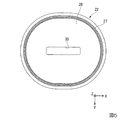
図13は、基板ステージ2に保持された基板Pの一例を示す図である。本実施形態においては、基板Pに露光対象領域であるショット領域Sがマトリクス状に複数配置される。制御装置6は、終端光学素子13の射出面12から射出される露光光ELに対して、第1保持部に保持されている基板PをY軸方向(走査方向)に移動しつつ、射出面12と基板Pとの間の液浸空間LSの液体LQを介して、射出面12から射出された露光光ELで、基板Pの複数のショット領域Sのそれぞれを順次露光する。
FIG. 13 is a diagram illustrating an example of the substrate P held on the
例えば基板Pの1つのショット領域Sを露光するために、制御装置6は、液浸空間LSが形成されている状態で、射出面12から射出される露光光EL(投影光学系PLの投影領域PR)に対して基板PをY軸方向に移動するとともに、その基板PのY軸方向への移動と同期して、照明系ILの照明領域IRに対してマスクMをY軸方向に移動しつつ、投影光学系PLと基板P上の液浸空間LSの液体LQとを介してそのショット領域Sに露光光ELを照射する。これにより、マスクMのパターンの像がそのショット領域Sに投影され、そのショット領域Sが射出面12から射出された露光光ELで露光される。
For example, in order to expose one shot region S of the substrate P, the control device 6 performs exposure light EL (projection region of the projection optical system PL) emitted from the
そのショット領域Sの露光が終了した後、制御装置6は、次のショット領域Sの露光を開始するために、液浸空間LSが形成されている状態で、基板PをXY平面内においてY軸と交差する方向(例えばX軸方向、あるいはXY平面内においてX軸及びY軸方向に対して傾斜する方向等)に移動し、次のショット領域Sを露光開始位置に移動する。その後、制御装置6は、そのショット領域Sの露光を開始する。 After the exposure of the shot area S is completed, the control device 6 moves the substrate P to the Y axis in the XY plane in the state where the immersion space LS is formed in order to start the exposure of the next shot area S. In a direction intersecting with (for example, the X-axis direction or a direction inclined with respect to the X-axis and Y-axis directions in the XY plane) and the next shot area S is moved to the exposure start position. Thereafter, the control device 6 starts exposure of the shot area S.
制御装置6は、基板P(基板ステージ2)上に液浸空間LSが形成されている状態で、射出面12からの露光光ELが照射される位置(投影領域PR)に対してショット領域をY軸方向に移動しながらそのショット領域を露光する動作と、そのショット領域の露光後、基板P(基板ステージ2)上に液浸空間LSが形成されている状態で、次のショット領域が露光開始位置に配置されるように、XY平面内においてY軸方向と交差する方向(例えばX軸方向、あるいはXY平面内においてX軸及びY軸方向に対して傾斜する方向等)に基板Pを移動する動作とを繰り返しながら、基板Pの複数のショット領域のそれぞれを順次露光する。
In the state where the immersion space LS is formed on the substrate P (substrate stage 2), the control device 6 sets the shot region with respect to the position (projection region PR) irradiated with the exposure light EL from the
以下の説明において、ショット領域を露光するために、基板P(基板ステージ2)上に液浸空間LSが形成されている状態で、射出面12からの露光光ELが照射される位置(投影領域PR)に対して基板P(ショット領域)をY軸方向に移動する動作を適宜、スキャン移動動作、と称する。また、あるショット領域の露光終了後、基板P(基板ステージ2)上に液浸空間LSが形成されている状態で、次のショット領域の露光が開始されるまでの間に、XY平面内において基板Pを移動する動作を適宜、ステップ移動動作、と称する。
In the following description, in order to expose the shot area, a position (projection area) where the exposure light EL from the
本実施形態において、スキャン移動動作は、あるショット領域Sが露光開始位置に配置されている状態から露光終了位置に配置される状態になるまで基板PがY軸方向に移動する動作を含む。ステップ移動動作は、あるショット領域Sが露光終了位置に配置されている状態から次のショット領域Sが露光開始位置に配置される状態になるまで基板PがXY平面内においてY軸方向と交差する方向に移動する動作を含む。 In the present embodiment, the scan movement operation includes an operation in which the substrate P moves in the Y-axis direction from a state in which a certain shot region S is arranged at the exposure start position to a state in which the shot area S is arranged at the exposure end position. In the step movement operation, the substrate P intersects with the Y-axis direction in the XY plane from a state where a certain shot area S is arranged at the exposure end position to a state where the next shot area S is arranged at the exposure start position. Includes movement in the direction.
露光開始位置は、あるショット領域Sの露光のために、そのショット領域SのY軸方向に関する一端部が投影領域PRを通過する時点の基板Pの位置を含む。露光終了位置は、露光光ELが照射されたそのショット領域SのY軸方向に関する他端部が投影領域PRを通過する時点の基板Pの位置を含む。 The exposure start position includes the position of the substrate P when one end of the shot area S in the Y-axis direction passes through the projection area PR for exposure of the shot area S. The exposure end position includes the position of the substrate P when the other end portion in the Y-axis direction of the shot area S irradiated with the exposure light EL passes through the projection area PR.
ショット領域Sの露光開始位置は、そのショット領域Sを露光するためのスキャン移動動作開始位置を含む。ショット領域Sの露光開始位置は、そのショット領域Sを露光開始位置に配置するためのステップ移動動作終了位置を含む。 The exposure start position of the shot area S includes a scan movement operation start position for exposing the shot area S. The exposure start position of the shot area S includes a step movement operation end position for arranging the shot area S at the exposure start position.
ショット領域Sの露光終了位置は、そのショット領域Sを露光するためのスキャン移動動作終了位置を含む。ショット領域Sの露光終了位置は、そのショット領域Sの露光終了後、次のショット領域Sを露光開始位置に配置するためのステップ移動動作開始位置を含む。 The exposure end position of the shot area S includes a scan movement operation end position for exposing the shot area S. The exposure end position of the shot area S includes a step movement operation start position for placing the next shot area S at the exposure start position after the exposure of the shot area S is completed.
以下の説明において、あるショット領域Sの露光のためにスキャン移動動作が行われる期間を適宜、スキャン移動期間、と称する。以下の説明において、あるショット領域Sの露光終了から次のショット領域Sの露光開始のためにステップ移動動作が行われる期間を適宜、ステップ移動期間、と称する。 In the following description, a period during which the scan movement operation is performed for exposure of a certain shot area S is appropriately referred to as a scan movement period. In the following description, a period during which the step movement operation is performed for the start of exposure of the next shot area S from the end of exposure of a certain shot area S is appropriately referred to as a step movement period.
スキャン移動期間は、あるショット領域Sの露光開始から露光終了までの露光期間を含む。ステップ移動期間は、あるショット領域Sの露光終了から次のショット領域Sの露光開始までの基板Pの移動期間を含む。 The scan movement period includes an exposure period from the start of exposure of a certain shot area S to the end of exposure. The step movement period includes a movement period of the substrate P from the end of exposure of a certain shot area S to the start of exposure of the next shot area S.
スキャン移動動作において、射出面12から露光光ELが射出される。スキャン移動動作において、基板P(物体)に露光光ELが照射される。ステップ移動動作において、射出面12から露光光ELが射出されない。ステップ移動動作において、基板P(物体)に露光光ELが照射されない。
In the scan movement operation, the exposure light EL is emitted from the
制御装置6は、スキャン移動動作とステップ移動動作とを繰り返しながら、基板Pの複数のショット領域Sのそれぞれを順次露光する。なお、スキャン移動動作は、主にY軸方向に関する等速移動である。ステップ移動動作は、加減速度移動を含む。例えば、あるショット領域Sの露光終了から次のショット領域Sの露光開始までの間のステップ移動動作は、Y軸方向に関する加減速移動及びX軸方向に関する加減速移動の一方又は両方を含む。 The control device 6 sequentially exposes each of the plurality of shot regions S of the substrate P while repeating the scan movement operation and the step movement operation. The scan movement operation is a constant speed movement mainly in the Y-axis direction. The step movement operation includes acceleration / deceleration movement. For example, the step movement operation from the end of exposure of a certain shot area S to the start of exposure of the next shot area S includes one or both of acceleration / deceleration movement in the Y-axis direction and acceleration / deceleration movement in the X-axis direction.
なお、スキャン移動動作及びステップ移動動作の少なくとも一部において、液浸空間LSの少なくとも一部が、基板ステージ2(カバー部材T)上に形成される場合がある。スキャン移動動作及びステップ移動動作の少なくとも一部において、液浸空間LSが基板Pと基板ステージ2(カバー部材T)とを跨ぐように形成される場合がある。基板ステージ2と計測ステージ3とが接近又は接触した状態で基板Pの露光が行われる場合、スキャン移動動作及びステップ移動動作の少なくとも一部において、液浸空間LSが基板ステージ2(カバー部材T)と計測ステージ3とを跨ぐように形成される場合がある。
In at least a part of the scan movement operation and the step movement operation, at least a part of the immersion space LS may be formed on the substrate stage 2 (cover member T). In at least part of the scan movement operation and the step movement operation, the immersion space LS may be formed so as to straddle the substrate P and the substrate stage 2 (cover member T). When the substrate P is exposed with the
制御装置6は、基板P上の複数のショット領域Sの露光条件に基づいて、駆動システム15を制御して、基板P(基板ステージ2)を移動する。複数のショット領域Sの露光条件は、例えば露光レシピと呼ばれる露光制御情報によって規定される。露光制御情報は、記憶装置7に記憶されている。
The control device 6 moves the substrate P (substrate stage 2) by controlling the
露光条件(露光制御情報)は、複数のショット領域Sの配列情報(基板Pにおける複数のショット領域Sそれぞれの位置)を含む。また、露光条件(露光制御情報)は、複数のショット領域Sのそれぞれの寸法情報(Y軸方向に関する寸法情報)を含む。 The exposure conditions (exposure control information) include arrangement information of the plurality of shot areas S (positions of the plurality of shot areas S on the substrate P). The exposure condition (exposure control information) includes dimension information (dimension information about the Y-axis direction) of each of the plurality of shot regions S.
制御装置6は、記憶装置7に記憶されている露光条件(露光制御情報)に基づいて、所定の移動条件で基板Pを移動しながら、複数のショット領域Sのそれぞれを順次露光する。基板P(物体)の移動条件は、移動速度、加速度、移動距離、移動方向、及びXY平面内における移動軌跡の少なくとも一つを含む。 Based on the exposure conditions (exposure control information) stored in the storage device 7, the control device 6 sequentially exposes each of the plurality of shot regions S while moving the substrate P under a predetermined movement condition. The movement condition of the substrate P (object) includes at least one of movement speed, acceleration, movement distance, movement direction, and movement locus in the XY plane.
一例として、複数のショット領域Sのそれぞれを順次露光するとき、制御装置6は、投影光学系PLの投影領域PRと基板Pとが、図13中、矢印Srに示す移動軌跡に沿って相対的に移動するように基板ステージ2を移動しつつ投影領域PRに露光光ELを照射して、液体LQを介して複数のショット領域Sのそれぞれを露光光ELで順次露光する。制御装置6は、スキャン移動動作とステップ移動動作とを繰り返しながら、複数のショット領域Sのそれぞれを順次露光する。
As an example, when sequentially exposing each of the plurality of shot regions S, the control device 6 causes the projection region PR of the projection optical system PL and the substrate P to be relative to each other along the movement locus indicated by the arrow Sr in FIG. The projection region PR is irradiated with the exposure light EL while moving the
本実施形態において、第2部材22は、基板Pの露光処理の少なくとも一部において移動する。第2部材22は、例えば液浸空間LSが形成されている状態で基板P(基板ステージ2)のステップ移動動作の少なくとも一部と並行して移動する。第2部材22は、例えば液浸空間LSが形成されている状態で基板P(基板ステージ2)のスキャン移動動作の少なくとも一部と並行して移動する。第2部材22の移動と並行して、射出面12から露光光ELが射出される。なお、スキャン移動動作中に第2部材22が移動しなくてもよい。すなわち、射出面12からの露光光ELの射出と並行して第2部材22が移動しなくてもよい。第2部材22は、例えば基板P(基板ステージ2)がステップ移動動作を行うとき、基板P(基板ステージ2)との相対移動(相対速度、相対加速度)が小さくなるように、移動してもよい。また、第2部材22は、基板P(基板ステージ2)がスキャン移動動作を行うとき、基板P(基板ステージ2)との相対移動(相対速度、相対加速度)が小さくなるように、移動してもよい。
In the present embodiment, the
図14は、基板Pを+X方向の成分を含むステップ移動を行いながら、ショット領域Sa、ショット領域Sb、及びショット領域Scのそれぞれを順次露光するときの基板Pの移動軌跡の一例を模式的に示す図である。ショット領域Sa、Sb、Scは、X軸方向に配置される。 FIG. 14 schematically illustrates an example of the movement trajectory of the substrate P when the shot area Sa, the shot area Sb, and the shot area Sc are sequentially exposed while performing the step movement of the substrate P including the component in the + X direction. FIG. The shot areas Sa, Sb, and Sc are arranged in the X-axis direction.
図14に示すように、ショット領域Sa、Sb、Scが露光されるとき、基板Pは、終端光学素子13の下において、位置d1からその位置d1に対して+Y側に隣り合う位置d2までの経路Tp1、位置d2からその位置d2に対して+X側に隣り合う位置d3までの経路Tp2、位置d3からその位置d3に対して−Y側に隣り合う位置d4までの経路Tp3、位置d4からその位置d4に対して+X側に隣り合う位置d5までの経路Tp4、及び位置d5からその位置d5に対して+Y側に隣り合う位置d6までの経路Tp5を順次移動する。位置d1、d2、d3、d4、d5、d6は、XY平面内における位置である。
As shown in FIG. 14, when the shot areas Sa, Sb, Sc are exposed, the substrate P is located under the last
経路Tp1の少なくとも一部は、Y軸と平行な直線である。経路Tp3の少なくとも一部は、Y軸と平行な直線である。経路Tp5の少なくとも一部は、Y軸と平行な直線を含む。経路Tp2は、位置d2.5を経由する曲線を含む。経路Tp4は、位置d4.5を経由する曲線を含む。位置d1は、経路Tp1の始点を含み、位置d2は、経路Tp1の終点を含む。位置d2は、経路Tp2の始点を含み、位置d3は、経路Tp2の終点を含む。位置d3は、経路Tp3の始点を含み、位置d4は、経路Tp3の終点を含む。位置d4は、経路Tp4の始点を含み、位置d5は、経路Tp4の終点を含む。位置d5は、経路Tp5の始点を含み、位置d6は、経路Tp5の終点を含む。経路Tp1は、基板Pが+Y方向に移動する経路である。経路Tp3は、基板Pが−Y方向に移動する経路である。経路Tp5は、基板Pが+Y方向に移動する経路である。経路Tp2及び経路Tp4は、基板Pが+方向を主成分とする方向に移動する経路である。 At least a part of the path Tp1 is a straight line parallel to the Y axis. At least a part of the path Tp3 is a straight line parallel to the Y axis. At least a part of the path Tp5 includes a straight line parallel to the Y axis. The path Tp2 includes a curve passing through the position d2.5. The path Tp4 includes a curve passing through the position d4.5. The position d1 includes the start point of the path Tp1, and the position d2 includes the end point of the path Tp1. The position d2 includes the start point of the path Tp2, and the position d3 includes the end point of the path Tp2. The position d3 includes the start point of the path Tp3, and the position d4 includes the end point of the path Tp3. The position d4 includes the start point of the path Tp4, and the position d5 includes the end point of the path Tp4. The position d5 includes the start point of the path Tp5, and the position d6 includes the end point of the path Tp5. The path Tp1 is a path along which the substrate P moves in the + Y direction. The path Tp3 is a path along which the substrate P moves in the −Y direction. The path Tp5 is a path along which the substrate P moves in the + Y direction. The path Tp2 and the path Tp4 are paths along which the substrate P moves in a direction whose main component is the + direction.
液浸空間LSが形成されている状態で基板Pが経路Tp1を移動するとき、液体LQを介してショット領域Saに露光光ELが照射される。液浸空間LSが形成されている状態で基板Pが経路Tp3を移動するとき、液体LQを介してショット領域Sbに露光光ELが照射される。液浸空間LSが形成されている状態で基板Pが経路Tp5を移動するとき、液体LQを介してショット領域Scに露光光ELが照射される。基板Pが経路Tp2及び経路Tp4を移動するとき、露光光ELは照射されない。 When the substrate P moves along the path Tp1 in the state where the immersion space LS is formed, the exposure light EL is irradiated to the shot region Sa through the liquid LQ. When the substrate P moves along the path Tp3 in a state where the immersion space LS is formed, the exposure light EL is irradiated to the shot region Sb through the liquid LQ. When the substrate P moves along the path Tp5 in a state where the immersion space LS is formed, the exposure light EL is irradiated to the shot region Sc through the liquid LQ. When the substrate P moves along the path Tp2 and the path Tp4, the exposure light EL is not irradiated.
基板Pが経路Tp1を移動する動作、経路Tp3を移動する動作、及び経路Tp5を移動する動作のそれぞれは、スキャン移動動作を含む。また、基板Pが経路Tp2を移動する動作、及び経路Tp4を移動する動作のそれぞれは、ステップ移動動作を含む。 Each of the movement of the substrate P along the path Tp1, the movement along the path Tp3, and the movement along the path Tp5 includes a scanning movement operation. Each of the operation of moving the substrate P along the path Tp2 and the operation of moving along the path Tp4 includes a step movement operation.
すなわち、基板Pが経路Tp1を移動する期間、経路Tp3を移動する期間、及び経路Tp5を移動する期間のそれぞれは、スキャン移動期間(露光期間)である。基板Pが経路Tp2を移動する期間、及び経路Tp4を移動する期間のそれぞれは、ステップ移動期間である。 That is, each of the period during which the substrate P moves along the path Tp1, the period during which the path Tp3 moves, and the period during which the substrate P moves along the path Tp5 is a scan movement period (exposure period). Each of the period during which the substrate P moves along the path Tp2 and the period during which the substrate P moves along the path Tp4 is a step movement period.
図15は、第2部材22の動作の一例を示す模式図である。図15は、第2部材22を上面25側から見た図である。
FIG. 15 is a schematic diagram illustrating an example of the operation of the
基板Pが位置d1にあるとき、第2部材22は、投影領域PR(露光光ELの光路K)に対して図15(A)に示す位置に配置される。基板Pが位置d2にあるとき、第2部材22は、投影領域PR(露光光ELの光路K)に対して図15(B)に示す位置に配置される。すなわち、基板Pの位置d1から位置d2へのスキャン移動動作中に、第2部材22は、基板Pのステップ移動の方向(+X方向)とは逆の−X方向に移動する。
When the substrate P is at the position d1, the
基板Pが位置d2.5にあるとき、第2部材22は、投影領域PR(露光光ELの光路K)に対して図15(C)に示す位置に配置される。基板Pが位置d3にあるとき、第2部材22は、投影領域PR(露光光ELの光路K)に対して図15(D)に示す位置に配置される。すなわち、基板Pの位置d2から位置d3へのステップ移動動作中に、第2部材22は、基板Pのステップ移動の方向(+X方向)と同じ+X方向に移動する。
When the substrate P is at the position d2.5, the
基板Pが位置d4にあるとき、第2部材22は、投影領域PR(露光光ELの光路K)に対して図15(E)に示す位置に配置される。すなわち、基板Pの位置d3から位置d4へのスキャン移動動作中に、第2部材22は、基板Pのステップ移動の方向(+X方向)とは逆の−X方向に移動する。
When the substrate P is at the position d4, the
基板Pが位置d4.5にあるとき、第2部材22は、投影領域PR(露光光ELの光路K)に対して図15(F)に示す位置に配置される。基板Pが位置d5にあるとき、第2部材22は、投影領域PR(露光光ELの光路K)に対して図15(G)に示す位置に配置される。すなわち、基板Pの位置d4から位置d5へのステップ移動動作中に、第2部材22は、基板Pのステップ移動の方向(+X方向)と同じ+X方向に移動する。
When the substrate P is at the position d4.5, the
基板Pが位置d6にあるとき、第2部材22は、投影領域PR(露光光ELの光路K)に対して図15(H)に示す位置に配置される。すなわち、基板Pの位置d5から位置d6へのスキャン動作移動中に、第2部材22は、基板Pのステップ移動の方向(+X方向)とは逆の−X方向に移動する。
When the substrate P is at the position d6, the
本実施形態において、図15(A)、図15(D)、図15(G)に示す第2部材22の位置は、X軸方向に関して規定された第2部材22の移動可能範囲(可動範囲)の最も+X側の端の位置(第2端部位置)である。図15(B)、図15(E)、図15(H)に示す第2部材22の位置は、X軸方向に関して規定された第2部材22の移動可能範囲(可動範囲)の最も−X側の端の位置(第1端部位置)である。図15(C)、図15(F)に示す第2部材22の位置は、X軸方向に関して規定された第2部材22の移動可能範囲(可動範囲)の中央の位置(中央位置)である。
In this embodiment, the position of the
基板Pが経路Tp1を移動するとき、第2部材22は、図15(A)に示す状態から図15(B)に示す状態に変化するように、−X方向に移動する。すなわち、第2部材22は、第2端部位置から中央位置を経て第1端部位置へ移動する。基板Pが経路Tp2を移動するとき、第2部材22は、図15(B)に示す状態から図15(C)に示す状態を経て図15(D)に示す状態に変化するように、+X方向に移動する。すなわち、第2部材22は、第1端部位置から中央位置を経て第2端部位置へ移動する。基板Pが経路Tp3を移動するとき、第2部材22は、図15(D)に示す状態から図15(E)に示す状態に変化するように、−X方向に移動する。すなわち、第2部材22は、第2端部位置から中央位置を経て第1端部位置へ移動する。基板Pが経路Tp4を移動するとき、第2部材22は、図15(E)に示す状態から図15(F)に示す状態を経て図15(G)に示す状態に変化するように、+X方向に移動する。すなわち、第2部材22は、第1端部位置から中央位置を経て第2端部位置へ移動する。基板Pが経路Tp5を移動するとき、第2部材22は、図15(G)に示す状態から図15(H)に示す状態に変化するように、−X方向に移動する。すなわち、第2部材22は、第2端部位置から中央位置を経て第1端部位置へ移動する。
When the substrate P moves along the path Tp1, the
すなわち、本実施形態において、第2部材22は、基板Pが経路Tp2に沿って移動する期間の少なくとも一部において、基板Pとの相対移動が小さくなるように、+X方向に移動する。換言すれば、第2部材22は、基板Pが+X方向の成分を含むステップ移動動作する期間の少なくとも一部に、X軸方向に関する基板Pとの相対速度が小さくなるように、+X方向に移動する。同様に、第2部材22は、基板Pが経路Tp4に沿って移動する期間の少なくとも一部において、X軸方向に関する基板Pとの相対速度が小さくなるように、+X方向に移動する。
That is, in the present embodiment, the
また、本実施形態において、第2部材22は、基板Pが経路Tp3に沿って移動する期間の少なくとも一部において、−X方向に移動する。これにより、基板Pの経路Tp3の移動後、経路Tp4の移動において、第2部材22が+X方向に移動しても露光光ELは開口35を通過可能である。基板Pが経路Tp1、Tp5を移動する場合も同様である。
In the present embodiment, the
すなわち、基板Pがスキャン移動動作と+X方向の成分を含むステップ移動動作とを繰り返す場合、ステップ移動動作中に、基板Pとの相対速度が小さくなるように第2部材22が第1端部位置から第2端部位置へ+X方向に移動し、スキャン移動動作中に、次のステップ移動動作において第2部材22が再度+X方向に移動できるように、第2部材22が第2端部位置から第1端部位置へ戻る。すなわち、基板Pが経スキャン移動動作する期間の少なくとも一部において、第2部材22が−X方向に移動するので、開口35の寸法が必要最小限に抑えられる。
That is, when the substrate P repeats the scan movement operation and the step movement operation including the component in the + X direction, the
また、本実施形態においては、第2部材22が第1端部位置(第2端部位置)に配置されても、流体回収部27の少なくとも一部は、基板P(物体)と対向し続ける。これにより、例えばステップ移動動作において、流体回収部27は、基板P(物体)上の液体LQを回収することができる。
In this embodiment, even if the
なお、図14及び図15を用いて説明した例においては、基板Pが位置d1、d3、d5にあるときに、第2部材22が第2端部位置に配置されることとした。基板Pが位置d1、d3、d5にあるときに、第2部材22が、中央位置に配置されてもよいし、中央位置と第2端部位置との間に配置されてもよい。
In the example described with reference to FIGS. 14 and 15, the
なお、図14及び図15を用いて説明した例においては、基板Pが位置d2、d4、d6にあるときに、第2部材22が第1端部位置に配置されることとした。基板Pが位置d2、d4、d6にあるときに、第2部材22が、中央位置に配置されてもよいし、中央位置と第1端部位置との間に配置されてもよい。
In the example described with reference to FIGS. 14 and 15, the
また、基板Pが位置d2.5、d4.5にあるときに、第2部材22が、中央位置とは異なる位置に配置されてもよい。すなわち、基板Pが位置d2.5、d4.5にあるときに、第2部材22が、例えば中央位置と第2端部位置との間に配置されてもよいし、中央位置と第1端部位置との間に配置されてもよい。
Further, when the substrate P is at the positions d2.5 and d4.5, the
以上説明したように、本実施形態によれば、流体回収部27を有する可動部材100に、少なくとも一部が変形可能な変形部材61を接続するので、可動部材100が移動しても、振動の発生が抑制される。また、振動の発生を抑制しつつ、流体回収部27から回収された液体LQを、第1流路101及び第2流路62を介して回収することができる。したがって、露光不良の発生及び不良デバイスの発生が抑制される。
As described above, according to the present embodiment, the
<第2実施形態>
第2実施形態について説明する。以下の説明において、上述の実施形態と同一又は同等の構成部分については同一の符号を付し、その説明を簡略若しくは省略する。
Second Embodiment
A second embodiment will be described. In the following description, the same or equivalent components as those of the above-described embodiment are denoted by the same reference numerals, and the description thereof is simplified or omitted.
図16は、本実施形態に係る配管システム60Bの一例を示す図である。配管システム60Bは、可動部材100に接続され、少なくとも一部が変形可能な変形部材(チューブ部材)61Bを有する。チューブ部材61Bは、可動部材100の第1流路101からの液体LQが流通可能な第2流路62Bを有する。
FIG. 16 is a diagram illustrating an example of a
チューブ部材61Bは、変形可能な柔軟部611と、柔軟部612よりも変形し難い屈曲部612とを有する。チューブ部材61Bは、柔軟部611を複数有する。また、チューブ部材61Bは、屈曲部612を複数有する。柔軟部611は、複数の屈曲部612の間に配置される。
The
本実施形態において、チューブ部材61Bは、蛇行するように屈曲部612を複数有する。複数の屈曲部612は、可動部材100の移動方向(X軸方向)に配置される。複数の柔軟部611のそれぞれは、実質的にY軸と平行に配置される。
In the present embodiment, the
チューブ部材61Bは、可動部材100の移動方向(X軸方向)に変形可能である。可動部材100が移動される可動範囲において、チューブ部材61Bは、弾性変形可能である。
The
以上説明したように、本実施形態においても、配管システム60Bが、少なくとも一部が変形可能なチューブ部材61Bを有するため、可動部材100が移動しても、振動の発生が抑制される。例えば、可動部材100が移動しても、支持フレーム53が振動することが抑制される。したがって、露光不良の発生、及び不良デバイスの発生が抑制される。
As described above, also in the present embodiment, the
本実施形態においては、チューブ部材61Bは、X軸方向に配置される複数の屈曲部612、及びそれら複数の屈曲部612の間に配置される柔軟部611を有するため、可動部材100が移動しても、チューブ部材61Bにおいて応力が集中すること抑制される。
In the present embodiment, the
なお、本実施形態において、屈曲部612が柔軟性を有してもよい。
In the present embodiment, the
<第3実施形態>
第3実施形態について説明する。以下の説明において、上述の実施形態と同一又は同等の構成部分については同一の符号を付し、その説明を簡略若しくは省略する。
<Third Embodiment>
A third embodiment will be described. In the following description, the same or equivalent components as those of the above-described embodiment are denoted by the same reference numerals, and the description thereof is simplified or omitted.
図17は、本実施形態に係る配管システム60Cの一例を示す図である。配管システム60Cは、可動部材100に接続され、少なくとも一部が変形可能な変形部材(チューブ部材)61Cを有する。チューブ部材61Cは、可動部材100の第1流路101からの液体LQが流通可能な第2流路62Cを有する。
FIG. 17 is a diagram illustrating an example of a
チューブ部材61Cは、柔軟性を有する。チューブ部材61Cは、合成樹脂製でもよい。チューブ部材61Cは、フッ素を含む合成樹脂製でもよい。チューブ部材61Cは、例えばPFA(Tetra fluoro ethylene-perfluoro alkylvinyl ether copolymer)を含んでもよい。チューブ部材61Cは、例えばPTFE(Poly tetra fluoroethylene)を含んでもよい。 The tube member 61C has flexibility. The tube member 61C may be made of a synthetic resin. The tube member 61C may be made of a synthetic resin containing fluorine. The tube member 61C may include, for example, PFA (Tetrafluoroethylene-perfluoroalkylvinyl ether copolymer). The tube member 61C may include, for example, PTFE (Poly tetrafluoroethylene).
チューブ部材61Cは、可動部材100の移動方向(X軸方向)と平行な軸(仮想軸)Jを巻くようにスパイラル状に形成される。
The
チューブ部材61Cは、可動部材100の移動方向(X軸方向)に変形可能である。可動部材100が移動される可動範囲において、チューブ部材61Cは、弾性変形可能である。本実施形態において、チューブ部材61Cは、コイルばねのように弾性変形可能である。
The
本実施形態においても、振動の発生が抑制される。したがって、露光不良の発生、及び不良デバイスの発生が抑制される。 Also in the present embodiment, the occurrence of vibration is suppressed. Therefore, the occurrence of exposure failure and the occurrence of defective devices are suppressed.
<第4実施形態>
第4実施形態について説明する。以下の説明において、上述の実施形態と同一又は同等の構成部分については同一の符号を付し、その説明を簡略若しくは省略する。
<Fourth embodiment>
A fourth embodiment will be described. In the following description, the same or equivalent components as those of the above-described embodiment are denoted by the same reference numerals, and the description thereof is simplified or omitted.
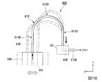
図18は、本実施形態に係る配管システム60Dの一例を示す図である。配管システム60Dは、可動部材100に接続され、少なくとも一部が変形可能な変形部材(チューブ部材)61Dを有する。チューブ部材61Dは、可動部材100の第1流路101からの液体LQが流通可能な第2流路62Dを有する。
FIG. 18 is a diagram illustrating an example of a
チューブ部材61Dの一端部は、可動部材100に接続される。チューブ部材61Dの他端部は、中継部材63に接続される。中継部材63の位置は、固定されている。
One end of the
可動部材100は、X軸方向に移動する。中継部材63は、可動部材100に対して、可動部材100の移動方向と平行な方向(X軸方向)に配置されている。図18に示す例では、中継部材63は、可動部材100に対して、−X側に配置されている。
The
チューブ部材61Dは、屈曲部612Dと、屈曲部612Dの一側(可動部材100側)に配置され、実質的にY軸と平行に配置されるストレート部611Dと、屈曲部612Dの他側(中継部材63側)に配置され、実質的にY軸と平行に配置されるストレート部611Dとを含む。チューブ部材61Dは、柔軟性(可撓性)を有する。チューブ部材61Dは、例えばポリオレフィンなどの合成樹脂を含む。
The
図18に示すように、可動部材100がX軸方向に移動することにより、チューブ部材61Dの少なくとも一部は変形する。例えば、可動部材100が−X方向に移動(中継部材63に近付くように移動)することにより、屈曲部612Dの一側のストレート部611Dと他側のストレート部611Dとが接近するとともに、屈曲部612Dの曲率が大きくなるように、チューブ部材61Dが変形する。可動部材100が+X方向に移動(中継部材63から離れるように移動)することにより、屈曲部612Dの一側のストレート部611Dと他側のストレート部611Dとが離れるとともに、屈曲部612Dの曲率が小さくなるように、チューブ部材61Dが変形する。可動部材100が移動される可動範囲において、チューブ部材61Dは、弾性変形可能である。
As shown in FIG. 18, when the
本実施形態においても、振動の発生が抑制される。したがって、露光不良の発生、及び不良デバイスの発生が抑制される。 Also in the present embodiment, the occurrence of vibration is suppressed. Therefore, the occurrence of exposure failure and the occurrence of defective devices are suppressed.
<第5実施形態>
第5実施形態について説明する。以下の説明において、上述の実施形態と同一又は同等の構成部分については同一の符号を付し、その説明を簡略若しくは省略する。
<Fifth Embodiment>
A fifth embodiment will be described. In the following description, the same or equivalent components as those of the above-described embodiment are denoted by the same reference numerals, and the description thereof is simplified or omitted.
図19は、本実施形態に係る配管システム60Eの一例を示す図である。配管システム60Eは、可動部材100に接続され、少なくとも一部が変形可能な変形部材(チューブ部材)61Eを有する。チューブ部材61Eは、可動部材100の第1流路101からの液体LQが流通可能な第2流路62Eを有する。
FIG. 19 is a diagram illustrating an example of a
チューブ部材61Eの一端部は、可動部材100に接続される。チューブ部材61Eの他端部は、中継部材63に接続される。中継部材63の位置は、固定されている。
One end of the
可動部材100は、X軸方向に移動する。中継部材63は、可動部材100に対して、可動部材100の移動方向と交差する方向(Y軸方向)に配置されている。図19に示す例では、中継部材63は、可動部材100に対して、+Y側に配置されている。
The
チューブ部材61Eは、屈曲部612Eと、屈曲部612Eの一側(可動部材100側)に配置され、実質的にX軸と平行に配置されるストレート部611Eと、屈曲部612Eの他側(中継部材63側)に配置され、実質的にX軸と平行に配置されるストレート部611Eとを含む。チューブ部材61Eは、柔軟性(可撓性)を有する。チューブ部材61Eは、例えばポリオレフィンなどの合成樹脂を含む。
The
図19に示すように、可動部材100がX軸方向に移動することにより、チューブ部材61Eの少なくとも一部は変形する。本実施形態においては、可動部材100がX軸方向に移動しても、屈曲部612Eの曲率は、ほぼ変化しない。可動部材100が移動される可動範囲において、チューブ部材61Eは、弾性変形可能である。
As shown in FIG. 19, when the
本実施形態においても、振動の発生が抑制される。したがって、露光不良の発生、及び不良デバイスの発生が抑制される。 Also in the present embodiment, the occurrence of vibration is suppressed. Therefore, the occurrence of exposure failure and the occurrence of defective devices are suppressed.
<第6実施形態>
第6実施形態について説明する。以下の説明において、上述の実施形態と同一又は同等の構成部分については同一の符号を付し、その説明を簡略若しくは省略する。
<Sixth Embodiment>
A sixth embodiment will be described. In the following description, the same or equivalent components as those of the above-described embodiment are denoted by the same reference numerals, and the description thereof is simplified or omitted.
図20(A)は、本実施形態に係る配管システム60Fの一例を示す図、図20(B)は、本実施形態に係る配管システム60Fの一部を示す断面図である。配管システム60Fは、少なくとも一部が可動部材100と対向し、可動部材100の第1流路101からの液体LQが流通可能な第2流路62Fを有し、少なくとも一部が可動部材100に対して相対移動可能な接続装置70を備えている。
FIG. 20A is a diagram illustrating an example of a
本実施形態において、接続装置70は、第1ジョイント部711を介して可動部材100と接続される第1リンク部材71と、第2ジョイント部72を介して第1リンク部材71と接続される第2リンク部材72とを有するリンク機構70Rを含む。
In the present embodiment, the
第2流路62Fは、第1リンク部材71及び第2リンク部材72に設けられる。第2流路62Fの一部分621Fが、第1リンク部材71の内部に形成される。第2流路62Fの一部分622Fが、第2リンク部材72の内部に形成される。
The
以下の説明において、第1リンク部材71に形成される第2流路62Fの一部分621Fを適宜、第1部分621F、と称する。第2リンク部材72に形成される第2流路62Fの一部分622Fを適宜、第2部分622F、と称する。
In the following description, a
第1流路101は、第2流路62F(第1部分621F)と接続される。流体回収部27から回収され、第1流路101に流入した液体LQの少なくとも一部は、第2流路62Fの第1部分621Fに流入する。
The
第1部分621Fは、第2部分622Fと接続される。第1流路101から第1部分621Fに流入した液体LQの少なくとも一部は、第2部分622Fに流入する。
The
配管システム60Fは、中継部材63Fを有する。中継部材63Fは、第3ジョイント部713を介して第2リンク部材72と接続される。中継部材63Fは、第2流路62F(第2部分622F)からの液体LQが流通可能な回収流路63FRを有する。回収流路63FRは、中継部材63Fの内部に形成される。
The
第2流路62F(第2部分622F)は、回収流路63FRと接続される。第1流路101から第2流路62F(第2部分622F)に流入した液体LQの少なくとも一部は、回収流路63FRに流入する。
The
中継部材63Fは、支持フレーム53に支持される。中継部材63Fは、支持フレーム53に固定される。中継部材63Fの位置は、固定される。支持フレーム53は、接続装置70を支持する。なお、中継部材63Fが接続装置70の少なくとも一部を支持し、支持フレーム53が中継部材63Fを介して接続装置70の少なくとも一部を支持してもよい。
The
回収流路63FRと液体回収装置27Cとが、流路27CRを介して接続される。回収流路63FR及び流路27CRは、液体回収装置27Cに通じる。第1流路101と、液体回収装置27Cに通じる回収流路63FRとが、接続装置70の第2流路62Fを介して接続される。流体回収部27からの液体LQは、第1流路101、第2流路62F、回収流路63FR、及び流路27CRを介して、液体回収装置27Cに回収される。
The recovery channel 63FR and the
接続装置70は、少なくとも一部が可動部材100と対向した状態で、可動部材100に対して相対移動する。本実施形態においては、第1リンク部材71は、少なくとも一部が可動部材100と対向した状態で、第1ジョイント部711を中心に、可動部材100に対してθZ方向に移動(回動、回転)可能である。
The
また、第2リンク部材72は、少なくとも一部が第1リンク部材71と対向した状態で、第2ジョイント部712を中心に、第1リンク部材71に対してθZ方向に移動(回動、回転)可能である。
The
また、第2リンク部材72は、少なくとも一部が中継部材63Fと対向した状態で、第3ジョイント部713を中心に、中継部材63Fに対してθZ方向に移動(回動、回転)可能である。
The
図20(B)は、第1ジョイント部711における断面図である。図20(B)に示すように、第1ジョイント部711において、第1流路101と第2流路62F(第1部分621F)とが接続されるように、可動部材100と第1リンク部材71とが接続される。第1リンク部材71の少なくとも一部と可動部材100とは、間隙を介して対向する。これにより、第1リンク部材71と可動部材100とは円滑に相対移動可能である。また、振動の発生が抑制される。
FIG. 20B is a cross-sectional view of the first
接続装置70は、第1ジョイント部711において第1流路101と第2流路62F(第1部分621F)との接続部をシールするシール部材73を有する。シール部材73により、第1ジョイント部711において液体LQの漏出が抑制される。
The
シール部材73は、潤滑性を有する。シール部材73の摩擦係数は、可動部材100及び接続装置70(第1リンク部材71)の摩擦係数よりも小さい。これにより、第1リンク部材71と可動部材100とは円滑に移動可能である。また、振動の発生が抑制される。
The
シール部材73は、耐薬品性を有する。シール部材73は、液体LQと接触した場合でも、液体LQに溶解し難い。換言すれば、シール部材73は、液体LQに対する溶出が少ない。これにより、第1流路101及び第2流路62Fを流れる液体LQの汚染が抑制される。
The
シール部材73は、合成樹脂製でもよい。シール部材73は、例えばフッ素を含む合成樹脂製でもよい。シール部材73は、例えばPTFE(Poly tetra fluoroethylene)を含んでもよい。
The
第2ジョイント部712及び第3ジョイント部713は、第1ジョイント部711と同等の構成である。
The second
すなわち、第2ジョイント部712において、第2流路62Fの第1部分621Fと第2部分622Fとが接続されるように、第1リンク部材71と第2リンク部材72とが接続される。第2リンク部材72の少なくとも一部と第1リンク部材71とは、間隙を介して対向する。第2ジョイント部712において第2流路62Fの第1部分621Fと第2部分622Fとの接続部をシールするシール部材が設けられる。
That is, in the second
第3ジョイント部713において、第2流路62F(第2部分622F)と回収流路63FRとが接続されるように、第2リンク部材72と中継部材63Fとが接続される。中継部材63Fの少なくとも一部と第2リンク部材72とは、間隙を介して対向する。第3ジョイント部713において第2流路62Fの第2部分622Fと回収流路63FRとの接続部をシールするシール部材が設けられる。
In the third
可動部材100は、XY平面内において移動可能である。本実施形態において、可動部材100は、X軸方向に移動する。可動部材100がX軸方向に移動することにより、可動部材100に対して、接続装置70の少なくとも一部がX軸方向に相対移動する。可動部材100が移動される可動範囲において、接続装置70の少なくとも一部は、相対移動可能である。例えば、図20(A)において、可動部材100が−X方向に移動(中継部材63Fに近付くように移動)する場合、第1リンク部材71と第2リンク部材72とがなす角度θが小さくなるように、第1リンク部材71と第2リンク部材72とが相対移動するとともに、第1リンク部材71と可動部材100とが相対移動し、第2リンク部材72と中継部材63Fとが相対移動する。可動部材100が+X方向に移動(中継部材63Fから離れるように移動)する場合、第1リンク部材71と第2リンク部材72とがなす角度θが大きくなるように、第1リンク部材71と第2リンク部材72とが相対移動するとともに、第1リンク部材71と可動部材100とが相対移動し、第2リンク部材72と中継部材63Fとが相対移動する。
The
以上説明したように、本実施形態によれば、少なくとも一部が可動部材100に対して相対移動可能な接続装置70を設けたので、可動部材100が移動しても、振動の発生が抑制される。したがって、露光不良の発生、及び不良デバイスの発生が抑制される。
As described above, according to the present embodiment, since the
<第7実施形態>
第7実施形態について説明する。以下の説明において、上述の実施形態と同一又は同等の構成部分については同一の符号を付し、その説明を簡略若しくは省略する。
<Seventh embodiment>
A seventh embodiment will be described. In the following description, the same or equivalent components as those of the above-described embodiment are denoted by the same reference numerals, and the description thereof is simplified or omitted.
図21は、本実施形態に係る配管システム60Gの一例を示す断面図である。配管システム60Gは、少なくとも一部が可動部材100と対向し、可動部材100の第1流路101からの液体LQが流通可能な第2流路62Gを有し、少なくとも一部が可動部材100に対して相対移動可能な接続装置70Bを備えている。第1流路101と液体回収装置27Cに通じる流路27CRとが第2流路62Gを介して接続される。
FIG. 21 is a cross-sectional view showing an example of a
本実施形態において、接続装置70Bは、可動部材100の少なくとも一部が対向可能な中継部材70Sを含む。第2流路62Gは、中継部材70Sの内部に形成される。
In the present embodiment, the
本実施形態において、可動部材100は、X軸方向に移動する。中継部材70Sと可動部材100とは、X軸方向に相対移動可能である。中継部材70Sは、少なくとも一部が可動部材100と対向した状態で、可動部材100に対して相対移動可能である。
In the present embodiment, the
本実施形態において、中継部材70Sの少なくとも一部は、支持フレーム53に接続される。中継部材70Sの位置は、固定される。なお、中継部材70Sが支持フレーム53に対して移動してもよい。
In the present embodiment, at least a part of the
可動部材100は、中継部材70Sの外面74と対向する対向面102を有する。外面74と対向面102とは間隙を介して対向する。なお、外面74と対向面102との間に気体軸受が設けられてもよい。
The
可動部材100にX軸方向に貫通する孔(貫通孔)が形成されてもよい。中継部材70Sは、その貫通孔の内側に配置されるロッド部材でもよい。外面74は、そのロッド部材の外面でもよい。対向面102は、可動部材100に形成された貫通孔の内面でもよい。
A hole (through hole) penetrating in the X-axis direction may be formed in the
対向面102に第1流路101の端部(開口)103が配置される。外面74に第2流路62Gの端部(開口)75が配置される。開口75は、開口103よりも大きい。開口103は、可動部材100の可動範囲において可動部材100がX軸方向に移動された場合においても、開口75と開口103とが対向し続けることができる程度の大きさを有する。
An end (opening) 103 of the
すなわち、可動部材100がX軸方向に移動した場合においても、第1流路101は、第2流路62Gと接続され続ける。流体回収部27から回収され、第1流路101に流入した液体LQの少なくとも一部は、第2流路62Gに流入することができる。
That is, even when the
第2流路62Gと液体回収装置27Cとが、流路27CRを介して接続される。流路27CRは、液体回収装置27Cに通じる。第1流路101と、液体回収装置27Cに通じる流路27CRとが、接続装置70Bの第2流路62Gを介して接続される。流体回収部27からの液体LQは、第1流路101、第2流路62G、及び流路27CRを介して、液体回収装置27Cに回収される。
The
接続装置70Bは、第1流路101と第2流路62Gとの接続部をシールするシール部材73Bを有する。上述の第6実施形態で説明したシール部材73と同様、シール部材73Bは、潤滑性などを有する。シール部材73Bにより、第1流路101と第2流路62Gとの接続部において液体LQの漏出が抑制される。
The
なお、開口75は、可動部材100がX軸方向に移動した場合においても、シール部材73Bと対向しない大きさを有する。すなわち、可動部材100がX軸方向に関して可動範囲を移動した場合において、開口75の内側にシール部材73Bが配置されないように、X軸方向に関する開口75の寸法が定められる。なお、可動部材100が移動した場合において、開口75の内側にシール部材73Bの少なくとも一部が配置されてもよい。
The
以上説明したように、本実施形態においても、可動部材100と接続装置70B(中継部材70S)とが相対移動可能である。また、可動部材100と接続装置70B(中継部材70S)とは、間隙を介して対向した状態で相対移動する。そのため、可動部材100が移動しても、振動の発生が抑制される。したがって、露光不良の発生、及び不良デバイスの発生が抑制される。
As described above, also in this embodiment, the
<第8実施形態>
第8実施形態について説明する。以下の説明において、上述の実施形態と同一又は同等の構成部分については同一の符号を付し、その説明を簡略若しくは省略する。
<Eighth Embodiment>
An eighth embodiment will be described. In the following description, the same or equivalent components as those of the above-described embodiment are denoted by the same reference numerals, and the description thereof is simplified or omitted.
図22(A)は、本実施形態に係る配管システム60Hの一例を示す断面図、図22(B)は、配管システム60Hの一例を示す側面図、図22(C)は、配管システム60Hの一部を示す模式図である。
22A is a cross-sectional view illustrating an example of the
配管システム60Hは、少なくとも一部が可動部材100と対向し、可動部材100の第1流路101からの液体LQが流通可能な第2流路62Hを有し、少なくとも一部が可動部材100に対して相対移動可能な接続装置70Cを備えている。第1流路101と液体回収装置27Cに通じる流路27CRとが第2流路62Hを介して接続される。
The
本実施形態において、接続装置70Cは、可動部材100の少なくとも一部が対向可能であり、可動部材100を移動可能に支持する支持面76を有する中継部材70Tを含む。第2流路62Hは、中継部材70Tの内部に形成される。
In the present embodiment, the
本実施形態において、可動部材100は、X軸方向に移動する。中継部材70Tと可動部材100とは、X軸方向に相対移動可能である。中継部材70Tは、少なくとも一部が可動部材100と対向した状態で、可動部材100に対して相対移動可能である。可動部材100は、中継部材70Tに支持された状態で、X軸方向に移動可能である。
In the present embodiment, the
本実施形態において、中継部材70Tの少なくとも一部は、支持フレーム53に接続される。本実施形態において、中継部材70Tは、支持フレーム53の下面53Bに接続された保持部材77に接続される。中継部材70Tは、保持部材77に固定される。中継部材70Tは、保持部材77を介して、支持フレーム53に接続される。中継部材70Tの位置は、固定される。
In the present embodiment, at least a part of the
以下の説明において、保持部材77及びその保持部材77に接続される中継部材70Tを合わせて適宜、中継装置90、と称する。中継装置90は、支持フレーム53に固定される。
In the following description, the holding
本実施形態において、可動部材100の少なくとも一部は、支持フレーム53と中継装置90との間の空間78の内側に配置される。中継装置90(中継部材70T)は、可動部材100を移動可能に支持する。空間78において可動部材100が可動範囲を移動しても、可動部材100と保持部材77とが接触しない程度に、空間78の大きさが定められる。
In the present embodiment, at least a part of the
可動部材100は、中継部材70Tの支持面76と対向する対向面104を有する。本実施形態において支持面76は上方(+Z側)を向く。対向面104は下方(−Z側)を向く。
The
支持面76と対向面104とは間隙を介して対向する。支持面76は、非接触で可動部材100を支持する。
The
図22(C)に示すように、支持面76と対向面104との間に気体軸受105が設けられる。本実施形態において、気体軸受105は、可動部材100に配置された多孔部材106の孔から支持面76と対向面104との間に供給される気体によって形成される。対向面104は、多孔部材106の下面を含む。なお、気体軸受105は、多孔部材106から供給される気体によって形成されなくてもよい。気体軸受105を形成するための、支持面76と対向面104との間に気体を供給する給気口と、支持面76と対向面104との間の気体の少なくとも一部を排出する排気口とが、可動部材100の対向面104及び中継部材70Tの支持面76の一方又は両方に設けられてもよい。
As shown in FIG. 22C, a
対向面104に第1流路101の端部(開口)107が配置される。支持面76に第2流路62Hの端部(開口)79が配置される。開口79は、開口107よりも大きい。開口107は、可動部材100の可動範囲において可動部材100がX軸方向に移動された場合においても、開口79と開口107とが対向し続けることができる程度の大きさを有する。
An end (opening) 107 of the
すなわち、可動部材100がX軸方向に移動した場合においても、第1流路101は、第2流路62Hと接続され続ける。流体回収部27から回収され、第1流路101に流入した液体LQの少なくとも一部は、第2流路62Hに流入することができる。
That is, even when the
第2流路62Hと液体回収装置27Cとが、流路27CRを介して接続される。流路27CRは、液体回収装置27Cに通じる。第1流路101と、液体回収装置27Cに通じる流路27CRとが、接続装置70Cの第2流路62Hを介して接続される。流体回収部27からの液体LQは、第1流路101、第2流路62H、及び流路27CRを介して、液体回収装置27Cに回収される。
The
接続装置70Cは、第1流路101と第2流路62Hとの接続部をシールするシール部を有してもよい。本実施形態においては、開口79及び開口107の外側に配置される気体軸受105によって、シール部が形成される。シール部(気体軸受105)により、第1流路101と第2流路62Hとの接続部において液体LQの漏出が抑制される。
The
以上説明したように、本実施形態においても、可動部材100と接続装置70C(中継部材70T)とは相対移動可能である。そのため、可動部材100が移動しても、振動の発生が抑制される。また、可動部材100と接続装置70C(中継部材70T)とは、間隙を介して対向した状態で相対移動する。そのため、可動部材100の移動に伴って発生する保持装置90に作用する反力を小さくすることができる。したがって、露光不良の発生、及び不良デバイスの発生が抑制される。
As described above, also in this embodiment, the
なお、本実施形態において、図23(A)及び図23(B)に示すように、支持フレーム53と中継装置90との間に、中継装置90を移動(揺動)可能に支持する支持装置80が設けられてもよい。支持装置80は、例えばヒンジ機構を含む。支持装置80は、保持部材77及びその保持部材77に接続される中継部材70Tを含む中継装置90を、X軸、Y軸、Z軸、θX、θY、及びθZの6つの方向に移動可能に支持する。
In the present embodiment, as shown in FIGS. 23A and 23B, a support device that supports the
上述の実施形態で説明したように、可動部材100(第2部材22、第2支持部材52)をガイドするガイド装置57及び気体軸受57Gが、第1支持部材51と可動部材100との間に設けられる。ガイド装置57は、可動部材100をX軸方向にガイドし、Y軸、Z軸、θX、θY、及びθZ方向に関する可動部材100の移動を制限する。気体軸受57Gにより、可動部材100は、第1支持部材21に対して非接触状態でX軸方向にガイドされる。
As described in the above embodiment, the
図23に示す例においては、支持装置80により中継装置90が支持フレーム53に対して移動可能であるため、可動部材100の移動に伴って発生する中継装置90に作用する反力をより小さくすることができる。また、中継装置90が支持フレーム53に対して移動可能であるため、気体軸受57Gにおける第1支持部材51と可動部材100との間隙の寸法、及び気体軸受105における中継部材70Tと可動部材100との間隙の寸法のそれぞれを適切な寸法に維持することができる。
In the example shown in FIG. 23, since the
なお、上述の第1〜第8実施形態において、図24に示すように、第1部材21の少なくとも一部が、終端光学素子13の射出面12と対向してもよい。すなわち、第1部材21の一部が、射出面12と基板P(物体)の上面との間に配置されてもよい。
In the first to eighth embodiments described above, as shown in FIG. 24, at least part of the
図24に示す例において、第1部材21は、開口34の周囲に配置された上面44を有する。開口34の上端の周囲に上面44が配置される。また、図24に示す例では、第2部材22の上面の一部も、射出面12と対向する。
In the example shown in FIG. 24, the
なお、上述の各実施形態において、図24に示すように、第1空間SP1に面するように液体供給部(液体供給口)3100が設けられてもよい。図24に示す例において、液体供給部3100は、第1空間SP1に面するように第1部材21の下面に配置される。なお、液体供給部3100は、第1空間SP1に面するように第2部材22の上面に配置されてもよい。
In each of the above-described embodiments, as shown in FIG. 24, a liquid supply unit (liquid supply port) 3100 may be provided so as to face the first space SP1. In the example shown in FIG. 24, the
液体供給部3100から液体LQが供給されることにより、例えば第3空間SP3に面する液体供給部31から供給された液体LQが第1空間SP1に流入しなくても、第1空間SP1が液体LQで満たされる。
By supplying the liquid LQ from the
なお、上述の各実施形態において、第2部材22が、射出面12と対向しなくてもよい。すなわち、第2部材22が、射出面12と基板P(物体)の上面との間に配置されなくてもよい。例えば、図25に示すように、第1部材21の下面が、射出面12よりも+Z側に配置されてもよい。すなわち、基板P(物体)の上面と射出面12との間隙の寸法が、基板Pの上面と第2部材22の下面との間隙の寸法よりも小さくてもよい。
In each embodiment described above, the
なお、上述の各実施形態において、Z軸方向に関する第1部材21の下面の位置(高さ)と射出面12の位置(高さ)とが実質的に等しくてもよい。第1部材21の下面が、射出面12よりも−Z側に配置されてもよい。
In each of the above-described embodiments, the position (height) of the lower surface of the
なお、上述の各実施形態において、基板P(物体)の上面と射出面12との間隙の寸法が、基板Pの上面と第2部材22の下面との間隙の寸法と実質的に等しくてもよい。
In each of the above-described embodiments, even if the size of the gap between the upper surface of the substrate P (object) and the
なお、上述の各実施形態において、第1部材21と終端光学素子13との間の空間から液体LQ及び気体の少なくとも一方を吸引する吸引口を第1部材21に設けてもよい。
In each of the above embodiments, the
なお、上述の各実施形態において、第1部材21は環状でなくてもよい。例えば、第1部材21は、終端光学素子13(光路K)の周囲の一部に配置されてもよい。例えば、第1部材21は、終端光学素子13(光路K)の周囲において複数配置されてもよい。
In each of the above-described embodiments, the
なお、上述の各実施形態において、制御装置6は、CPU等を含むコンピュータシステムを含む。また、制御装置6は、コンピュータシステムと外部装置との通信を実行可能なインターフェースを含む。記憶装置7は、例えばRAM等のメモリ、ハードディスク、CD−ROM等の記録媒体を含む。記憶装置7には、コンピュータシステムを制御するオペレーティングシステム(OS)がインストールされ、露光装置EXを制御するためのプログラムが記憶されている。 In each of the above-described embodiments, the control device 6 includes a computer system including a CPU and the like. The control device 6 includes an interface capable of executing communication between the computer system and an external device. The storage device 7 includes a memory such as a RAM, and a recording medium such as a hard disk and a CD-ROM. The storage device 7 is installed with an operating system (OS) that controls the computer system, and stores a program for controlling the exposure apparatus EX.
なお、制御装置6に、入力信号を入力可能な入力装置が接続されていてもよい。入力装置は、キーボード、マウス等の入力機器、あるいは外部装置からのデータを入力可能な通信装置等を含む。また、液晶表示ディスプレイ等の表示装置が設けられていてもよい。 Note that an input device capable of inputting an input signal may be connected to the control device 6. The input device includes an input device such as a keyboard and a mouse, or a communication device that can input data from an external device. Further, a display device such as a liquid crystal display may be provided.
記憶装置7に記録されているプログラムを含む各種情報は、制御装置(コンピュータシステム)6が読み取り可能である。記憶装置7には、制御装置6に、露光光が射出される光学部材の射出面と基板との間の露光光の光路に満たされた液体を介して露光光で基板を露光する液浸露光装置の制御を実行させるプログラムが記録されている。 Various information including programs recorded in the storage device 7 can be read by the control device (computer system) 6. In the storage device 7, liquid immersion exposure is performed in which the control device 6 exposes the substrate with the exposure light through the liquid filled in the optical path of the exposure light between the exit surface of the optical member from which the exposure light is emitted and the substrate. A program for executing control of the apparatus is recorded.
記憶装置7に記録されているプログラムは、上述の実施形態に従って、制御装置6に、露光光の光路の周囲の少なくとも一部に配置され、光学部材の下方で移動可能な物体上に液体の液浸空間を形成可能であり、液浸空間の液体の少なくとも一部を回収可能な回収部及び回収部からの液体が流通可能な第1流路を有する可動部材を含む液浸部材を用いて、光学部材の下方で移動可能な基板上に液体の液浸空間を形成することと、液浸空間の液体を介して射出面から射出される露光光で基板を露光することと、基板の露光の少なくとも一部において、可動部材を移動することと、回収部から回収され第1流路を流れる液体を、可動部材に接続され、少なくとも一部が変形可能な変形部材の第2流路を介して回収することと、を実行させてもよい。 According to the above-described embodiment, the program recorded in the storage device 7 is arranged in the control device 6 in at least a part of the periphery of the optical path of the exposure light, and the liquid liquid is placed on the object that is movable below the optical member. By using a liquid immersion member that can form an immersion space, and includes a recovery unit that can recover at least part of the liquid in the immersion space and a movable member that has a first flow path through which the liquid from the recovery unit can flow. Forming a liquid immersion space on a substrate movable under the optical member, exposing the substrate with exposure light emitted from the exit surface through the liquid in the immersion space, and exposing the substrate At least in part, the movable member is moved, and the liquid recovered from the recovery unit and flowing in the first flow path is connected to the movable member via at least a part of the second flow path of the deformable member that can be deformed. Collecting and executing
また、記憶装置7に記録されているプログラムは、上述の実施形態に従って、制御装置6に、露光光の光路の周囲の少なくとも一部に配置され、光学部材の下方で移動可能な物体上に液体の液浸空間を形成可能であり、液浸空間の液体の少なくとも一部を回収可能な回収部及び回収部からの液体が流通可能な第1流路を有する可動部材を含む液浸部材を用いて、光学部材の下方で移動可能な基板上に液体の液浸空間を形成することと、液浸空間の液体を介して射出面から射出される露光光で基板を露光することと、基板の露光の少なくとも一部において、可動部材を移動することと、回収部から回収され第1流路を流れる液体を、少なくとも一部が可動部材と対向し、少なくとも一部が可動部材に対して相対移動可能な接続装置の第2流路、及び第2流路を介して第1流路と接続される第3流路を介して液体回収装置で回収することと、を実行させてもよい。 In addition, the program recorded in the storage device 7 is arranged on the control device 6 according to the above-described embodiment, and is placed on at least a part of the periphery of the optical path of the exposure light, and is liquid on an object that is movable below the optical member. A liquid immersion member including a movable part having a recovery part capable of recovering at least a part of the liquid in the liquid immersion space and a first channel through which the liquid from the recovery part can flow. Forming a liquid immersion space on the substrate movable under the optical member, exposing the substrate with exposure light emitted from the exit surface through the liquid in the immersion space, and In at least a part of the exposure, the movable member is moved, and the liquid collected from the collection unit and flowing through the first flow path is at least partially opposed to the movable member and at least partially moved relative to the movable member. A second flow path of the possible connecting device, And recovering a liquid recovery device through the third flow path connected to the first flow path through the beauty second flow path, it may be executed.
記憶装置7に記憶されているプログラムが制御装置6に読み込まれることにより、基板ステージ2、計測ステージ3、及び液浸部材5等、露光装置EXの各種の装置が協働して、液浸空間LSが形成された状態で、基板Pの液浸露光等、各種の処理を実行する。
When the program stored in the storage device 7 is read into the control device 6, various devices of the exposure apparatus EX such as the
なお、上述の各実施形態においては、投影光学系PLの終端光学素子13の射出面12側(像面側)の光路Kが液体LQで満たされているが、投影光学系PLが、例えば国際公開第2004/019128号パンフレットに開示されているような、終端光学素子13の入射側(物体面側)の光路も液体LQで満たされる投影光学系でもよい。
In each of the above-described embodiments, the optical path K on the
なお、上述の各実施形態においては、液体LQが水であることとしたが、水以外の液体でもよい。液体LQは、露光光ELに対して透過性であり、露光光ELに対して高い屈折率を有し、投影光学系PLあるいは基板Pの表面を形成する感光材(フォトレジスト)等の膜に対して安定なものが好ましい。例えば、液体LQが、ハイドロフロロエーテル(HFE)、過フッ化ポリエーテル(PFPE)、フォンブリンオイル等のフッ素系液体でもよい。また、液体LQが、種々の流体、例えば、超臨界流体でもよい。 In each of the above-described embodiments, the liquid LQ is water, but a liquid other than water may be used. The liquid LQ is transmissive to the exposure light EL, has a high refractive index with respect to the exposure light EL, and forms a film such as a photosensitive material (photoresist) that forms the surface of the projection optical system PL or the substrate P. A stable material is preferred. For example, the liquid LQ may be a fluorinated liquid such as hydrofluoroether (HFE), perfluorinated polyether (PFPE), or fomblin oil. Further, the liquid LQ may be various fluids such as a supercritical fluid.
なお、上述の各実施形態においては、基板Pが、半導体デバイス製造用の半導体ウエハを含むこととしたが、例えばディスプレイデバイス用のガラス基板、薄膜磁気ヘッド用のセラミックウエハ、あるいは露光装置で用いられるマスクまたはレチクルの原版(合成石英、シリコンウエハ)等を含んでもよい。 In each of the above-described embodiments, the substrate P includes a semiconductor wafer for manufacturing a semiconductor device. For example, the substrate P is used in a glass substrate for a display device, a ceramic wafer for a thin film magnetic head, or an exposure apparatus. A mask or reticle master (synthetic quartz, silicon wafer) or the like may also be included.
なお、上述の各実施形態においては、露光装置EXが、マスクMと基板Pとを同期移動してマスクMのパターンを走査露光するステップ・アンド・スキャン方式の走査型露光装置(スキャニングステッパ)であることとしたが、例えばマスクMと基板Pとを静止した状態でマスクMのパターンを一括露光し、基板Pを順次ステップ移動させるステップ・アンド・リピート方式の投影露光装置(ステッパ)でもよい。 In each of the above-described embodiments, the exposure apparatus EX is a step-and-scan type scanning exposure apparatus (scanning stepper) that scans and exposes the pattern of the mask M by moving the mask M and the substrate P synchronously. However, for example, a step-and-repeat projection exposure apparatus (stepper) that performs batch exposure of the pattern of the mask M while the mask M and the substrate P are stationary and sequentially moves the substrate P stepwise may be used.
また、露光装置EXが、ステップ・アンド・リピート方式の露光において、第1パターンと基板Pとをほぼ静止した状態で、投影光学系を用いて第1パターンの縮小像を基板P上に転写した後、第2パターンと基板Pとをほぼ静止した状態で、投影光学系を用いて第2パターンの縮小像を第1パターンと部分的に重ねて基板P上に一括露光する露光装置(スティッチ方式の一括露光装置)でもよい。また、スティッチ方式の露光装置が、基板P上で少なくとも2つのパターンを部分的に重ねて転写し、基板Pを順次移動させるステップ・アンド・スティッチ方式の露光装置でもよい。 In addition, the exposure apparatus EX transfers a reduced image of the first pattern onto the substrate P using the projection optical system while the first pattern and the substrate P are substantially stationary in the step-and-repeat exposure. Thereafter, with the second pattern and the substrate P substantially stationary, an exposure apparatus (stitch method) that collectively exposes a reduced image of the second pattern on the substrate P by partially overlapping the first pattern using a projection optical system. (Batch exposure apparatus). Further, the stitch type exposure apparatus may be a step-and-stitch type exposure apparatus in which at least two patterns are partially overlapped and transferred on the substrate P, and the substrate P is sequentially moved.
また、露光装置EXが、例えば米国特許第6611316号に開示されているような、2つのマスクのパターンを、投影光学系を介して基板上で合成し、1回の走査露光によって基板上の1つのショット領域をほぼ同時に二重露光する露光装置でもよい。また、露光装置EXが、プロキシミティ方式の露光装置、ミラープロジェクション・アライナー等でもよい。 Further, the exposure apparatus EX combines two mask patterns as disclosed in, for example, US Pat. No. 6,611,316 on the substrate via the projection optical system, and 1 on the substrate by one scanning exposure. An exposure apparatus that double-exposes two shot areas almost simultaneously may be used. Further, the exposure apparatus EX may be a proximity type exposure apparatus, a mirror projection aligner, or the like.
また、上述の各実施形態において、露光装置EXが、米国特許第6341007号、米国特許第6208407号、米国特許第6262796号等に開示されているような、複数の基板ステージを備えたツインステージ型の露光装置でもよい。例えば、図26に示すように、露光装置EXが2つの基板ステージ2001、2002を備えている場合、射出面12と対向するように配置可能な物体は、一方の基板ステージ、その一方の基板ステージの第1保持部に保持された基板、他方の基板ステージ、及びその他方の基板ステージの第1保持部に保持された基板の少なくとも一つを含む。
In each of the above-described embodiments, the exposure apparatus EX is a twin stage type having a plurality of substrate stages as disclosed in US Pat. No. 6,341,007, US Pat. No. 6,208,407, US Pat. No. 6,262,796, and the like. The exposure apparatus may be used. For example, as shown in FIG. 26, when the exposure apparatus EX includes two
また、露光装置EXが、複数の基板ステージと計測ステージとを備えた露光装置でもよい。 The exposure apparatus EX may be an exposure apparatus that includes a plurality of substrate stages and measurement stages.
露光装置EXが、基板Pに半導体素子パターンを露光する半導体素子製造用の露光装置でもよいし、液晶表示素子製造用又はディスプレイ製造用の露光装置でもよいし、薄膜磁気ヘッド、撮像素子(CCD)、マイクロマシン、MEMS、DNAチップ、あるいはレチクル又はマスクなどを製造するための露光装置でもよい。 The exposure apparatus EX may be an exposure apparatus for manufacturing a semiconductor element that exposes a semiconductor element pattern on the substrate P, an exposure apparatus for manufacturing a liquid crystal display element or a display, a thin film magnetic head, an image sensor (CCD). An exposure apparatus for manufacturing a micromachine, a MEMS, a DNA chip, or a reticle or mask may be used.
なお、上述の実施形態においては、光透過性の基板上に所定の遮光パターン(又は位相パターン・減光パターン)を形成した光透過型マスクを用いたが、このマスクに代えて、例えば米国特許第6778257号に開示されているような、露光すべきパターンの電子データに基づいて透過パターン又は反射パターン、あるいは発光パターンを形成する可変成形マスク(電子マスク、アクティブマスク、あるいはイメージジェネレータとも呼ばれる)を用いてもよい。また、非発光型画像表示素子を備える可変成形マスクに代えて、自発光型画像表示素子を含むパターン形成装置を備えるようにしてもよい。 In the above-described embodiment, a light-transmitting mask in which a predetermined light-shielding pattern (or phase pattern / dimming pattern) is formed on a light-transmitting substrate is used. A variable shaped mask (also called an electronic mask, an active mask, or an image generator) that forms a transmission pattern, a reflection pattern, or a light emission pattern based on electronic data of a pattern to be exposed, as disclosed in No. 6778257 It may be used. Further, a pattern forming apparatus including a self-luminous image display element may be provided instead of the variable molding mask including the non-luminous image display element.
上述の各実施形態においては、露光装置EXが投影光学系PLを備えることとしたが、投影光学系PLを用いない露光装置及び露光方法に、上述の各実施形態で説明した構成要素を適用してもよい。例えば、レンズ等の光学部材と基板との間に液浸空間を形成し、その光学部材を介して、基板に露光光を照射する露光装置及び露光方法に、上述の各実施形態で説明した構成要素を適用してもよい。 In each of the above embodiments, the exposure apparatus EX includes the projection optical system PL. However, the components described in the above embodiments are applied to an exposure apparatus and an exposure method that do not use the projection optical system PL. May be. For example, an exposure apparatus and an exposure method for forming an immersion space between an optical member such as a lens and a substrate and irradiating the substrate with exposure light via the optical member are described in the above embodiments. Elements may be applied.
また、露光装置EXが、例えば国際公開第2001/035168号パンフレットに開示されているような、干渉縞を基板P上に形成することによって基板P上にライン・アンド・スペースパターンを露光する露光装置(リソグラフィシステム)でもよい。 The exposure apparatus EX exposes a line-and-space pattern on the substrate P by forming interference fringes on the substrate P as disclosed in, for example, WO 2001/035168. (Lithography system).
上述の実施形態の露光装置EXは、上述の各構成要素を含む各種サブシステムを、所定の機械的精度、電気的精度、光学的精度を保つように、組み立てることで製造される。これら各種精度を確保するために、この組み立ての前後には、各種光学系については光学的精度を達成するための調整、各種機械系については機械的精度を達成するための調整、各種電気系については電気的精度を達成するための調整が行われる。各種サブシステムから露光装置への組み立て工程は、各種サブシステム相互の、機械的接続、電気回路の配線接続、気圧回路の配管接続等が含まれる。この各種サブシステムから露光装置への組み立て工程の前に、各サブシステム個々の組み立て工程があることはいうまでもない。各種サブシステムの露光装置への組み立て工程が終了した後、総合調整が行われ、露光装置全体としての各種精度が確保される。なお、露光装置の製造は温度及びクリーン度等が管理されたクリーンルームで行うことが望ましい。 The exposure apparatus EX of the above-described embodiment is manufactured by assembling various subsystems including the above-described components so as to maintain predetermined mechanical accuracy, electrical accuracy, and optical accuracy. In order to ensure these various accuracies, before and after assembly, various optical systems are adjusted to achieve optical accuracy, various mechanical systems are adjusted to achieve mechanical accuracy, and various electrical systems are Adjustments are made to achieve electrical accuracy. The assembly process from the various subsystems to the exposure apparatus includes mechanical connection, electrical circuit wiring connection, pneumatic circuit piping connection and the like between the various subsystems. Needless to say, there is an assembly process for each subsystem before the assembly process from the various subsystems to the exposure apparatus. After the assembly process of the various subsystems to the exposure apparatus is completed, comprehensive adjustment is performed to ensure various accuracies as the entire exposure apparatus. The exposure apparatus is preferably manufactured in a clean room where the temperature, cleanliness, etc. are controlled.
半導体デバイス等のマイクロデバイスは、図27に示すように、マイクロデバイスの機能・性能設計を行うステップ201、この設計ステップに基づいたマスク(レチクル)を製作するステップ202、デバイスの基材である基板を製造するステップ203、上述の実施形態に従って、マスクのパターンからの露光光で基板を露光すること、及び露光された基板を現像することを含む基板処理(露光処理)を含む基板処理ステップ204、デバイス組み立てステップ(ダイシング工程、ボンディング工程、パッケージ工程などの加工プロセスを含む)205、検査ステップ206等を経て製造される。
As shown in FIG. 27, a microdevice such as a semiconductor device includes a
なお、上述の各実施形態の要件は、適宜組み合わせることができる。また、一部の構成要素を用いない場合もある。また、法令で許容される限りにおいて、上述の各実施形態及び変形例で引用した露光装置等に関する全ての公開公報及び米国特許の開示を援用して本文の記載の一部とする。 Note that the requirements of the above-described embodiments can be combined as appropriate. Some components may not be used. In addition, as long as permitted by law, the disclosure of all published publications and US patents related to the exposure apparatus and the like cited in the above embodiments and modifications are incorporated herein by reference.
2…基板ステージ、3…計測ステージ、5…液浸部材、6…制御装置、7…記憶装置、8A…基準フレーム、8B…装置フレーム、12…射出面、13…終端光学素子、21…第1部材、22…第2部材、23…下面、24…流体回収部、25…上面、26…下面、27…流体回収部、27C…流体回収装置、27CR…流路、29…外側面、30…内側面、31…液体供給部、32…駆動装置、34…開口、35…開口、36…多孔部材、37…多孔部材、51…第1支持部材、52…第2支持部材、53…支持フレーム、54…移動フレーム、55…防振装置、56…駆動装置、60…配管システム、61…変形部材、62…第2流路、62F…第2流路、621F…第1部分、622F…第2部分、63…中継部材、63R…回収流路、70…接続装置、70R…リンク機構、71…第1リンク部材、72…第2リンク部材、100…可動部材、101…第1流路、611…柔軟部、612…屈曲部、711…第1ジョイント部、712…第2ジョイント部、713…第3ジョイント部、EL…露光光、EX…露光装置、GS…気体、IL…照明系、K…光路、LQ…液体、LS…液浸空間、P…基板。
DESCRIPTION OF
Claims (21)
前記露光光が射出される射出面を有する光学部材と、
前記露光光の光路の周囲の少なくとも一部に配置され、前記光学部材の下方で移動可能な物体上に前記液体の液浸空間を形成可能であり、前記液浸空間の液体の少なくとも一部を回収可能な第1回収部及び前記第1回収部からの前記液体が流通可能な第1流路を有する可動部材を含む液浸部材と、
前記可動部材に接続され、前記第1流路からの前記液体が流通可能な第2流路を有し、少なくとも一部が変形可能な変形部材と、を備え、
前記液浸部材は、前記光学部材の周囲の少なくとも一部に配置される第1部材と、前記第1部材の下方において前記物体が対向可能に配置され、前記第1部材に対して可動な第2部材と、を有し、
前記可動部材は、前記第2部材を含み、
前記第2部材は、前記第1回収部を有し、
前記第1部材は、前記液浸空間を形成するための液体を供給する供給部と前記液浸空間の液体の少なくとも一部を回収可能な第2回収部を有する露光装置。 An exposure apparatus that exposes a substrate with exposure light through a liquid,
An optical member having an exit surface from which the exposure light is emitted;
An immersion space for the liquid can be formed on an object that is disposed at least around the optical path of the exposure light and is movable below the optical member, and at least a part of the liquid in the immersion space is formed. a liquid immersion member which the liquid from the first collecting portion and the first collecting part capable of recovering comprises a movable member having a first flow path can flow,
A deformable member connected to the movable member and having a second flow path through which the liquid from the first flow path can circulate, and at least a part of which is deformable .
The liquid immersion member includes a first member disposed at least at a part of the periphery of the optical member and a first member disposed below the first member so that the object can be opposed to the first member, and is movable with respect to the first member. Two members,
The movable member includes the second member,
The second member has the first recovery part,
Said first member, that have a second recovery unit which is capable of recovering at least a portion of the liquid supply portion for supplying the liquid for forming the liquid immersion space the immersion space exposure apparatus.
前記変形部材は、前記可動部材の移動方向に変形可能である請求項1又は2に記載の露光装置。 The movable member is moved in a plane perpendicular to the optical axis of the optical member;
The retainer has an exposure apparatus according to claim 1 or 2 which is deformable in the moving direction of the movable member.
前記液浸部材の少なくとも一部を支持する支持フレームと、
前記基準フレーム及び前記支持フレームを支持する装置フレームと、を備え、
前記変形部材は、前記支持フレームに支持される請求項1〜4のいずれか一項に記載の露光装置。 A reference frame that supports the optical member;
A support frame that supports at least a portion of the liquid immersion member;
An apparatus frame that supports the reference frame and the support frame,
The retainer has an exposure apparatus according to any one of claims 1 to 4, which is supported by the support frame.
前記露光光が射出される射出面を有する光学部材と、
前記露光光の光路の周囲の少なくとも一部に配置され、前記光学部材の下方で移動可能な物体上に前記液体の液浸空間を形成可能であり、前記液浸空間の液体の少なくとも一部を回収可能な第1回収部及び前記第1回収部からの前記液体が流通可能な第1流路を有する可動部材を含む液浸部材と、
少なくとも一部が前記可動部材と対向し、前記第1流路からの前記液体が流通可能な第2流路を有し、少なくとも一部が前記可動部材に対して相対移動可能な接続装置と、を備え、
前記第1流路と液体回収装置に通じる第3流路とが前記第2流路を介して接続され、
前記液浸部材は、前記光学部材の周囲の少なくとも一部に配置される第1部材と、前記第1部材の下方において前記物体が対向可能に配置され、前記第1部材に対して可動な第2部材と、を有し、
前記可動部材は、前記第2部材を含み、
前記第2部材は、前記第1回収部を有し、
前記第1部材は、前記液浸空間を形成するための液体を供給する供給部と前記液浸空間の液体の少なくとも一部を回収可能な第2回収部を有する露光装置。 An exposure apparatus that exposes a substrate with exposure light through a liquid,
An optical member having an exit surface from which the exposure light is emitted;
An immersion space for the liquid can be formed on an object that is disposed at least around the optical path of the exposure light and is movable below the optical member, and at least a part of the liquid in the immersion space is formed. a liquid immersion member which the liquid from the first collecting portion and the first collecting part capable of recovering comprises a movable member having a first flow path can flow,
A connection device having at least a portion facing the movable member, a second flow path through which the liquid from the first flow path can flow, and at least a portion movable relative to the movable member; With
The first flow path and the third flow path leading to the liquid recovery device are connected via the second flow path ;
The liquid immersion member includes a first member disposed at least at a part of the periphery of the optical member and a first member disposed below the first member so that the object can be opposed to the first member, and is movable with respect to the first member. Two members,
The movable member includes the second member,
The second member has the first recovery part,
Said first member, that have a second recovery unit which is capable of recovering at least a portion of the liquid supply portion for supplying the liquid for forming the liquid immersion space the immersion space exposure apparatus.
前記液浸部材の少なくとも一部を支持する支持フレームと、
前記基準フレーム及び前記支持フレームを支持する装置フレームと、を備え、
前記接続装置は、前記支持フレームに支持される請求項6又は7に記載の露光装置。 A reference frame that supports the optical member;
A support frame that supports at least a portion of the liquid immersion member;
An apparatus frame that supports the reference frame and the support frame,
The exposure apparatus according to claim 6 , wherein the connection device is supported by the support frame.
前記第1回収部及び前記第2回収部のうちの少なくとも一方は、前記多孔部材を含む請求項1〜9のいずれか一項に記載の露光装置。 Comprising a porous member disposed so that the object can face each other;
The exposure apparatus according to any one of claims 1 to 9 , wherein at least one of the first recovery unit and the second recovery unit includes the porous member.
前記液浸空間が形成された状態で、前記基板は、前記光学部材の光軸と実質的に垂直な面内において、第1経路を移動後、第2経路を移動し、
前記第1経路において、前記基板の移動は、前記面内における第1軸と実質的に平行な第1方向への移動を含み、
前記第2経路において、前記基板の移動は、前記面内において前記第1軸と直交する第2軸と実質的に平行な第2方向への移動を含み、
前記可動部材は、前記基板が前記第2経路を移動する期間の少なくとも一部において、前記第2方向に移動する請求項1〜14のいずれか一項に記載の露光装置。 The object includes the substrate;
In a state where the immersion space is formed, the substrate moves in the plane substantially perpendicular to the optical axis of the optical member and then moves in the second path,
In the first path, the movement of the substrate includes movement in a first direction substantially parallel to the first axis in the plane;
In the second path, the movement of the substrate includes a movement in a second direction substantially parallel to a second axis orthogonal to the first axis in the plane,
Said movable member, at least part of the period in which the substrate moves the second path, an exposure apparatus according to any one of claims 1 to 14, to move in the second direction.
前記第3経路において、前記基板の移動は、前記第1方向の反対の第3方向への移動を含み、
前記可動部材は、前記基板が前記第3経路を移動する期間の少なくとも一部において、前記第2方向の反対の第4方向に移動する請求項15又は16に記載の露光装置。 The substrate moves along the third path after moving along the second path,
In the third path, the movement of the substrate includes movement in a third direction opposite to the first direction;
The exposure apparatus according to claim 15 or 16 , wherein the movable member moves in a fourth direction opposite to the second direction in at least a part of a period during which the substrate moves in the third path.
露光された前記基板を現像することと、を含むデバイス製造方法。 Exposing the substrate using the exposure apparatus according to any one of claims 1 to 17 ,
Developing the exposed substrate. A device manufacturing method.
前記露光光の光路の周囲の少なくとも一部に配置され、前記光学部材の下方で移動可能な物体上に前記液体の液浸空間を形成可能であり、前記液浸空間の液体の少なくとも一部を回収可能な第1回収部及び前記第1回収部からの前記液体が流通可能な第1流路を有する可動部材を含む液浸部材を用いて、前記光学部材の下方で移動可能な前記基板上に前記液体の液浸空間を形成することと、
前記液浸空間の前記液体を介して前記射出面から射出される前記露光光で前記基板を露光することと、
前記基板の露光の少なくとも一部において、前記可動部材を移動することと、
前記第1回収部から回収され前記第1流路を流れる液体を、前記可動部材に接続され、少なくとも一部が変形可能な変形部材の第2流路を介して回収することと、を含み、
前記液浸部材は、前記光学部材の周囲の少なくとも一部に配置される第1部材と、前記第1部材の下方において前記物体が対向可能に配置され、前記第1部材に対して可動な第2部材と、を有し、
前記可動部材は、前記第2部材を含み、
前記第1部材に設けられた供給部から前記液浸空間を形成するための液体を供給することと、
前記第2部材に設けられた前記第1回収部によって、前記液浸空間の液体の少なくとも一部を回収することと、
前記第1部材に設けられた第2回収部によって、前記液浸空間の液体の少なくとも一部を回収することと、をさらに含む露光方法。 An exposure method for exposing the substrate with exposure light through a liquid between an emission surface of the optical member and the substrate,
An immersion space for the liquid can be formed on an object that is disposed at least around the optical path of the exposure light and is movable below the optical member, and at least a part of the liquid in the immersion space is formed. using the liquid immersion member including a movable member to which the liquid from the first collecting portion and the first collecting part capable of recovering comprises a first flow path can flow, the optical member movable on the substrate below Forming a liquid immersion space in
Exposing the substrate with the exposure light emitted from the exit surface through the liquid in the immersion space;
Moving the movable member in at least part of the exposure of the substrate;
The liquid is recovered through said first flow path from said first recovery unit, connected to said movable member, viewed including the at least a portion is recovered via the second channel of the deformable deformable member, the ,
The liquid immersion member includes a first member disposed at least at a part of the periphery of the optical member and a first member disposed below the first member so that the object can be opposed to the first member, and is movable with respect to the first member. Two members,
The movable member includes the second member,
Supplying a liquid for forming the immersion space from a supply unit provided in the first member;
Recovering at least a portion of the liquid in the immersion space by the first recovery part provided in the second member;
Wherein the second recovery unit provided in the first member, at least a possible part of the recovering, further including an exposure method of the liquid in the immersion space.
前記露光光の光路の周囲の少なくとも一部に配置され、前記光学部材の下方で移動可能な物体上に前記液体の液浸空間を形成可能であり、前記液浸空間の液体の少なくとも一部を回収可能な第1回収部及び前記第1回収部からの前記液体が流通可能な第1流路を有する可動部材を含む液浸部材を用いて、前記光学部材の下方で移動可能な前記基板上に前記液体の液浸空間を形成することと、
前記液浸空間の前記液体を介して前記射出面から射出される前記露光光で前記基板を露光することと、
前記基板の露光の少なくとも一部において、前記可動部材を移動することと、
前記第1回収部から回収され前記第1流路を流れる液体を、少なくとも一部が前記可動部材と対向し、少なくとも一部が前記可動部材に対して相対移動可能な接続装置の第2流路、及び前記第2流路を介して前記第1流路と接続される第3流路を介して液体回収装置で回収することと、を含み、
前記液浸部材は、前記光学部材の周囲の少なくとも一部に配置される第1部材と、前記第1部材の下方において前記物体が対向可能に配置され、前記第1部材に対して可動な第2部材と、を有し、
前記可動部材は、前記第2部材を含み、
前記第1部材に設けられた供給部から前記液浸空間を形成するための液体を供給することと、
前記第2部材に設けられた前記第1回収部によって、前記液浸空間の液体の少なくとも一部を回収することと、
前記第1部材に設けられた第2回収部によって、前記液浸空間の液体の少なくとも一部を回収することと、をさらに含む露光方法。 An exposure method for exposing the substrate with exposure light through a liquid between an emission surface of the optical member and the substrate,
An immersion space for the liquid can be formed on an object that is disposed at least around the optical path of the exposure light and is movable below the optical member, and at least a part of the liquid in the immersion space is formed. using the liquid immersion member including a movable member to which the liquid from the first collecting portion and the first collecting part capable of recovering comprises a first flow path can flow, the optical member movable on the substrate below Forming a liquid immersion space in
Exposing the substrate with the exposure light emitted from the exit surface through the liquid in the immersion space;
Moving the movable member in at least part of the exposure of the substrate;
The liquid recovered from the first recovery part and flowing through the first flow path is at least partly opposed to the movable member, and at least part of the second flow path of the connection device that is movable relative to the movable member. and I saw including a and recovering a liquid recovery device through the third channel to be connected to the first flow path through said second flow path,
The liquid immersion member includes a first member disposed at least at a part of the periphery of the optical member and a first member disposed below the first member so that the object can be opposed to the first member, and is movable with respect to the first member. Two members,
The movable member includes the second member,
Supplying a liquid for forming the immersion space from a supply unit provided in the first member;
Recovering at least a portion of the liquid in the immersion space by the first recovery part provided in the second member;
Wherein the second recovery unit provided in the first member, at least a possible part of the recovering, further including an exposure method of the liquid in the immersion space.
露光された前記基板を現像することと、を含むデバイス製造方法。 Exposing the substrate using the exposure method according to claim 19 or 20 ,
Developing the exposed substrate. A device manufacturing method.
Priority Applications (6)
| Application Number | Priority Date | Filing Date | Title |
|---|---|---|---|
| JP2012285783A JP6119242B2 (en) | 2012-12-27 | 2012-12-27 | Exposure apparatus, exposure method, and device manufacturing method |
| PCT/JP2013/084694 WO2014104107A1 (en) | 2012-12-27 | 2013-12-25 | Exposure device, exposure method, device production method, program, and recording medium |
| EP13867127.6A EP2940713B1 (en) | 2012-12-27 | 2013-12-25 | Exposure apparatus, exposure method, and device manufacturing method |
| EP17196156.8A EP3330799B1 (en) | 2012-12-27 | 2013-12-25 | Exposure apparatus, exposing method and device manufacturing method |
| HK16102132.7A HK1214406A1 (en) | 2012-12-27 | 2016-02-25 | Exposure device, exposure method, device production method, program, and recording medium |
| HK18110210.3A HK1250794A1 (en) | 2012-12-27 | 2018-08-08 | Exposure apparatus, exposing method and device manufacturing method |
Applications Claiming Priority (1)
| Application Number | Priority Date | Filing Date | Title |
|---|---|---|---|
| JP2012285783A JP6119242B2 (en) | 2012-12-27 | 2012-12-27 | Exposure apparatus, exposure method, and device manufacturing method |
Publications (3)
| Publication Number | Publication Date |
|---|---|
| JP2014127697A JP2014127697A (en) | 2014-07-07 |
| JP2014127697A5 JP2014127697A5 (en) | 2015-11-26 |
| JP6119242B2 true JP6119242B2 (en) | 2017-04-26 |
Family
ID=51021185
Family Applications (1)
| Application Number | Title | Priority Date | Filing Date |
|---|---|---|---|
| JP2012285783A Active JP6119242B2 (en) | 2012-12-27 | 2012-12-27 | Exposure apparatus, exposure method, and device manufacturing method |
Country Status (4)
| Country | Link |
|---|---|
| EP (2) | EP2940713B1 (en) |
| JP (1) | JP6119242B2 (en) |
| HK (2) | HK1214406A1 (en) |
| WO (1) | WO2014104107A1 (en) |
Families Citing this family (4)
| Publication number | Priority date | Publication date | Assignee | Title |
|---|---|---|---|---|
| NL2009692A (en) | 2011-12-07 | 2013-06-10 | Asml Netherlands Bv | A lithographic apparatus and a device manufacturing method. |
| CN109690413B (en) | 2016-09-12 | 2021-04-13 | Asml荷兰有限公司 | Fluid handling structure for a lithographic apparatus |
| KR102446678B1 (en) | 2017-12-15 | 2022-09-23 | 에이에스엠엘 네델란즈 비.브이. | Fluid handling structures, lithographic apparatus, methods of using the fluid handling structures, and methods of using the lithographic apparatus |
| CN112684665A (en) * | 2020-12-25 | 2021-04-20 | 浙江启尔机电技术有限公司 | Immersion liquid supply and recovery device |
Family Cites Families (24)
| Publication number | Priority date | Publication date | Assignee | Title |
|---|---|---|---|---|
| CN1244021C (en) | 1996-11-28 | 2006-03-01 | 株式会社尼康 | Photoetching device and exposure method |
| USRE40043E1 (en) | 1997-03-10 | 2008-02-05 | Asml Netherlands B.V. | Positioning device having two object holders |
| US6897963B1 (en) | 1997-12-18 | 2005-05-24 | Nikon Corporation | Stage device and exposure apparatus |
| US6208407B1 (en) | 1997-12-22 | 2001-03-27 | Asm Lithography B.V. | Method and apparatus for repetitively projecting a mask pattern on a substrate, using a time-saving height measurement |
| WO2001035168A1 (en) | 1999-11-10 | 2001-05-17 | Massachusetts Institute Of Technology | Interference lithography utilizing phase-locked scanning beams |
| US6452292B1 (en) | 2000-06-26 | 2002-09-17 | Nikon Corporation | Planar motor with linear coil arrays |
| JP2002154495A (en) * | 2000-11-21 | 2002-05-28 | Mitsubishi Heavy Ind Ltd | Microgravitational environment vibration absorbing link mechanism |
| WO2002069049A2 (en) | 2001-02-27 | 2002-09-06 | Asml Us, Inc. | Simultaneous imaging of two reticles |
| TW529172B (en) | 2001-07-24 | 2003-04-21 | Asml Netherlands Bv | Imaging apparatus |
| JP2005536775A (en) | 2002-08-23 | 2005-12-02 | 株式会社ニコン | Projection optical system, photolithography method and exposure apparatus, and method using exposure apparatus |
| KR20050085235A (en) * | 2002-12-10 | 2005-08-29 | 가부시키가이샤 니콘 | Exposure system and device producing method |
| KR101238114B1 (en) | 2003-09-03 | 2013-02-27 | 가부시키가이샤 니콘 | Apparatus and method for providing fluid for immersion lithography |
| US7589822B2 (en) | 2004-02-02 | 2009-09-15 | Nikon Corporation | Stage drive method and stage unit, exposure apparatus, and device manufacturing method |
| JP5167572B2 (en) * | 2004-02-04 | 2013-03-21 | 株式会社ニコン | Exposure apparatus, exposure method, and device manufacturing method |
| KR101441777B1 (en) * | 2004-03-25 | 2014-09-22 | 가부시키가이샤 니콘 | Exposure apparatus and method for manufacturing device |
| SG153813A1 (en) | 2004-06-09 | 2009-07-29 | Nikon Corp | Substrate holding device, exposure apparatus having same, exposure method, method for producing device, and liquid repellent plate |
| TWI424260B (en) | 2005-03-18 | 2014-01-21 | 尼康股份有限公司 | A board member, a substrate holding device, an exposure apparatus and an exposure method, and a device manufacturing method |
| JP4567651B2 (en) * | 2005-11-16 | 2010-10-20 | エーエスエムエル ネザーランズ ビー.ブイ. | Exposure apparatus and device manufacturing method |
| US7864292B2 (en) | 2005-11-16 | 2011-01-04 | Asml Netherlands B.V. | Lithographic apparatus and device manufacturing method |
| EP1983555B1 (en) | 2006-01-19 | 2014-05-28 | Nikon Corporation | Movable body drive method, movable body drive system, pattern formation method, pattern forming apparatus, exposure method, exposure apparatus and device manufacturing method |
| US8477283B2 (en) * | 2006-05-10 | 2013-07-02 | Nikon Corporation | Exposure apparatus and device manufacturing method |
| JP4366407B2 (en) * | 2007-02-16 | 2009-11-18 | キヤノン株式会社 | Exposure apparatus and device manufacturing method |
| JP2009088037A (en) * | 2007-09-28 | 2009-04-23 | Nikon Corp | Exposure method and device manufacturing method, and exposure apparatus |
| US9823580B2 (en) * | 2012-07-20 | 2017-11-21 | Nikon Corporation | Liquid immersion member, exposure apparatus, exposing method, method for manufacturing device, program, and recording medium |
-
2012
- 2012-12-27 JP JP2012285783A patent/JP6119242B2/en active Active
-
2013
- 2013-12-25 WO PCT/JP2013/084694 patent/WO2014104107A1/en active Application Filing
- 2013-12-25 EP EP13867127.6A patent/EP2940713B1/en active Active
- 2013-12-25 EP EP17196156.8A patent/EP3330799B1/en active Active
-
2016
- 2016-02-25 HK HK16102132.7A patent/HK1214406A1/en not_active IP Right Cessation
-
2018
- 2018-08-08 HK HK18110210.3A patent/HK1250794A1/en unknown
Also Published As
| Publication number | Publication date |
|---|---|
| EP2940713A1 (en) | 2015-11-04 |
| EP3330799B1 (en) | 2020-03-04 |
| HK1250794A1 (en) | 2019-01-11 |
| EP3330799A1 (en) | 2018-06-06 |
| HK1214406A1 (en) | 2016-07-22 |
| EP2940713B1 (en) | 2017-11-22 |
| JP2014127697A (en) | 2014-07-07 |
| EP2940713A4 (en) | 2016-11-02 |
| WO2014104107A1 (en) | 2014-07-03 |
Similar Documents
| Publication | Publication Date | Title |
|---|---|---|
| JP6601527B2 (en) | Exposure apparatus, exposure method, and device manufacturing method | |
| JP6569717B2 (en) | Immersion member, exposure apparatus, and device manufacturing method | |
| JP6406250B2 (en) | Immersion member, exposure apparatus, and device manufacturing method | |
| JP6583453B2 (en) | Exposure apparatus and device manufacturing method | |
| JP6119242B2 (en) | Exposure apparatus, exposure method, and device manufacturing method | |
| JP2014120693A (en) | Liquid immersion member, exposure apparatus, exposure method, device manufacturing method, program, and recording medium | |
| JP2014154700A (en) | Exposure device, exposure method, method of manufacturing device, program, and recording medium | |
| JP6212884B2 (en) | Exposure apparatus, exposure method, and device manufacturing method | |
| JP2014086678A (en) | Liquid immersion member, exposure device, exposure method, device manufacturing method, program, and storage medium | |
| JP2014096481A (en) | Liquid immersion member, exposure system, exposure method, method for manufacturing device, program, and recording medium | |
| JP2014120691A (en) | Liquid immersion member, exposure apparatus, exposure method, device manufacturing method, program, and recording medium | |
| JP2014086456A (en) | Liquid immersion member, exposure device, exposure method, device manufacturing method, program, and storage medium | |
| JP2014093479A (en) | Liquid immersion member, exposure apparatus, exposure method, device manufacturing method, program, and recording medium | |
| JP2015173202A (en) | Immersion exposure apparatus, exposure method, and program | |
| JP2013219351A (en) | Liquid immersion member, exposure apparatus, exposure method, device manufacturing method, program, and recording medium | |
| JP2014011205A (en) | Exposure device, exposure method, and device manufacturing method |
Legal Events
| Date | Code | Title | Description |
|---|---|---|---|
| A521 | Request for written amendment filed |
Free format text: JAPANESE INTERMEDIATE CODE: A523 Effective date: 20151007 |
|
| A621 | Written request for application examination |
Free format text: JAPANESE INTERMEDIATE CODE: A621 Effective date: 20151007 |
|
| A131 | Notification of reasons for refusal |
Free format text: JAPANESE INTERMEDIATE CODE: A131 Effective date: 20160823 |
|
| A601 | Written request for extension of time |
Free format text: JAPANESE INTERMEDIATE CODE: A601 Effective date: 20161024 |
|
| A521 | Request for written amendment filed |
Free format text: JAPANESE INTERMEDIATE CODE: A523 Effective date: 20161221 |
|
| TRDD | Decision of grant or rejection written | ||
| A01 | Written decision to grant a patent or to grant a registration (utility model) |
Free format text: JAPANESE INTERMEDIATE CODE: A01 Effective date: 20170228 |
|
| A61 | First payment of annual fees (during grant procedure) |
Free format text: JAPANESE INTERMEDIATE CODE: A61 Effective date: 20170313 |
|
| R150 | Certificate of patent or registration of utility model |
Ref document number: 6119242 Country of ref document: JP Free format text: JAPANESE INTERMEDIATE CODE: R150 |
|
| R250 | Receipt of annual fees |
Free format text: JAPANESE INTERMEDIATE CODE: R250 |
|
| R250 | Receipt of annual fees |
Free format text: JAPANESE INTERMEDIATE CODE: R250 |
|
| R250 | Receipt of annual fees |
Free format text: JAPANESE INTERMEDIATE CODE: R250 |
|
| R250 | Receipt of annual fees |
Free format text: JAPANESE INTERMEDIATE CODE: R250 |
|
| R250 | Receipt of annual fees |
Free format text: JAPANESE INTERMEDIATE CODE: R250 |