JP6084578B2 - Combination of tray and vacuum cleaner to clean the floor - Google Patents
Combination of tray and vacuum cleaner to clean the floor Download PDFInfo
- Publication number
- JP6084578B2 JP6084578B2 JP2013552319A JP2013552319A JP6084578B2 JP 6084578 B2 JP6084578 B2 JP 6084578B2 JP 2013552319 A JP2013552319 A JP 2013552319A JP 2013552319 A JP2013552319 A JP 2013552319A JP 6084578 B2 JP6084578 B2 JP 6084578B2
- Authority
- JP
- Japan
- Prior art keywords
- tray
- head
- cleaning device
- liquid
- brush
- Prior art date
- Legal status (The legal status is an assumption and is not a legal conclusion. Google has not performed a legal analysis and makes no representation as to the accuracy of the status listed.)
- Expired - Fee Related
Links
Images


Classifications
-
- A—HUMAN NECESSITIES
- A47—FURNITURE; DOMESTIC ARTICLES OR APPLIANCES; COFFEE MILLS; SPICE MILLS; SUCTION CLEANERS IN GENERAL
- A47L—DOMESTIC WASHING OR CLEANING; SUCTION CLEANERS IN GENERAL
- A47L11/00—Machines for cleaning floors, carpets, furniture, walls, or wall coverings
- A47L11/29—Floor-scrubbing machines characterised by means for taking-up dirty liquid
- A47L11/292—Floor-scrubbing machines characterised by means for taking-up dirty liquid having rotary tools
-
- A—HUMAN NECESSITIES
- A46—BRUSHWARE
- A46B—BRUSHES
- A46B17/00—Accessories for brushes
- A46B17/06—Devices for cleaning brushes after use
-
- A—HUMAN NECESSITIES
- A47—FURNITURE; DOMESTIC ARTICLES OR APPLIANCES; COFFEE MILLS; SPICE MILLS; SUCTION CLEANERS IN GENERAL
- A47L—DOMESTIC WASHING OR CLEANING; SUCTION CLEANERS IN GENERAL
- A47L11/00—Machines for cleaning floors, carpets, furniture, walls, or wall coverings
- A47L11/29—Floor-scrubbing machines characterised by means for taking-up dirty liquid
- A47L11/30—Floor-scrubbing machines characterised by means for taking-up dirty liquid by suction
- A47L11/302—Floor-scrubbing machines characterised by means for taking-up dirty liquid by suction having rotary tools
-
- A—HUMAN NECESSITIES
- A47—FURNITURE; DOMESTIC ARTICLES OR APPLIANCES; COFFEE MILLS; SPICE MILLS; SUCTION CLEANERS IN GENERAL
- A47L—DOMESTIC WASHING OR CLEANING; SUCTION CLEANERS IN GENERAL
- A47L11/00—Machines for cleaning floors, carpets, furniture, walls, or wall coverings
- A47L11/40—Parts or details of machines not provided for in groups A47L11/02 - A47L11/38, or not restricted to one of these groups, e.g. handles, arrangements of switches, skirts, buffers, levers
-
- A—HUMAN NECESSITIES
- A47—FURNITURE; DOMESTIC ARTICLES OR APPLIANCES; COFFEE MILLS; SPICE MILLS; SUCTION CLEANERS IN GENERAL
- A47L—DOMESTIC WASHING OR CLEANING; SUCTION CLEANERS IN GENERAL
- A47L9/00—Details or accessories of suction cleaners, e.g. mechanical means for controlling the suction or for effecting pulsating action; Storing devices specially adapted to suction cleaners or parts thereof; Carrying-vehicles specially adapted for suction cleaners
- A47L9/0009—Storing devices ; Supports, stands or holders
- A47L9/0063—External storing devices; Stands, casings or the like for the storage of suction cleaners
Description
本発明は、一般的に、掃除されるべき床面に接触するための少なくとも1つのブラシが回転可能に配置された、床面を掃除するための掃除装置のヘッドを洗浄するための方法に関する。 The present invention relates generally to a method for cleaning a head of a cleaning device for cleaning a floor, on which at least one brush for contacting the floor to be cleaned is rotatably arranged.
特に、本発明はまた、トレイと床面を掃除するための掃除装置との組み合わせであって、前記掃除装置は、掃除されるべき床面に面するための開口側を持つヘッドと、前記ヘッドにおいて回転可能に配置された、掃除されるべき床面に接触するための少なくとも1つのブラシと、を有し、前記トレイは、前記掃除装置の前記ヘッドの少なくとも一部を受容及び収容し、前記ヘッドの前記開口側をカバーするように構成され、前記トレイは、底部と前記底部に接続された起立壁とを有し、前記底部は、前記掃除装置の前記ヘッドを支持するように機能し、前記起立壁は、前記掃除装置の前記ヘッドを囲むように合わせて機能する組み合わせに関する。 In particular, the present invention is also a combination of a tray and a cleaning device for cleaning a floor surface, the cleaning device comprising a head having an open side for facing the floor surface to be cleaned, and the head At least one brush for contacting the floor surface to be cleaned, which is rotatably arranged in the tray, wherein the tray receives and houses at least part of the head of the cleaning device, The tray is configured to cover the opening side of the head, the tray has a bottom portion and an upright wall connected to the bottom portion, and the bottom portion functions to support the head of the cleaning device, The standing wall relates to a combination that functions so as to surround the head of the cleaning device.
床面を掃除するための種々のタイプの掃除装置が、実際に知られている。斯かる掃除装置の良く知られた一例は、吸引力の影響下で床のような面から埃及び塵を取り除くことが可能な電気掃除機である。他の例は、掃除されるべき床面に面するための開口側を持つヘッドと、該ヘッドに回転可能に配置された、掃除されるべき床面に接触するための少なくとも1つのブラシと、を有する装置である。本発明はこの種の掃除装置に関し、該装置は電気掃除機のような該ヘッドにおける吸引力を実現するための手段を有しても良いが、斯かる手段なしでも実現可能である。 Various types of cleaning devices for cleaning floor surfaces are actually known. A well-known example of such a cleaning device is a vacuum cleaner that can remove dust and dirt from a floor-like surface under the influence of suction. Another example is a head having an open side for facing the floor surface to be cleaned, and at least one brush for contacting the floor surface to be cleaned, rotatably disposed on the head; It is an apparatus having. The present invention relates to a cleaning device of this type, which may have means for realizing the suction force in the head, such as a vacuum cleaner, but can also be realized without such means.
掃除装置のブラシは、複数のブラシ毛を備える。これらブラシ毛が極端に軟らかく柔軟であっても良い。例えば、ブラシ毛は、10km当たり150gよりも少ない線形質量密度を持っても良い。斯かる場合においては、床面の掃除動作は、ブラシが使用されるときに通常予期されるように該床面を擦ることにより実行されるのではなく、ブラシの回転の間に、床面に対するブラシ毛の接触と非接触とを交互に行うことにより実行される。実際には、ブラシの1回転の間、汚れた床面から粒子及び/又は液滴を、該粒子及び/又は液滴がブラシ毛に接着する又は少なくともブラシ毛により初期位置から押し出されるという事実に基づいて取り除き、該ブラシ毛が床面に接触せず完全に広げられることができる位置に到達したときに、該粒子及び/又は液滴を振り捨てる。ブラシが配置された掃除装置のヘッドにおいては、粒子及び/又は液滴を受容し、ことによると粒子及び/又は液滴をこれら粒子及び/又は液滴が集められる空間に向けて搬送するための手段が存在する。掃除装置は、粒子及び/又は液滴がブラシ毛から離されたときに該粒子及び/又は液滴を所望の方向に向けるため、例えば真空を生成することにより、該ヘッドにおいて吸引力を実現するための手段を備えても良い。 The brush of the cleaning device includes a plurality of brush hairs. These brush hairs may be extremely soft and flexible. For example, the bristles may have a linear mass density of less than 150 g per 10 km. In such a case, the floor cleaning action is not performed by rubbing the floor as would normally be expected when the brush is used, but against the floor during the rotation of the brush. This is performed by alternately performing contact and non-contact of the bristle. In practice, due to the fact that during one rotation of the brush, particles and / or droplets from a dirty floor surface, the particles and / or droplets adhere to the brush bristles or at least be pushed out of the initial position by the bristles. Remove the particles and / or droplets when they reach a position where the bristles can be fully spread out without touching the floor surface. In the head of the cleaning device in which the brush is arranged, for receiving particles and / or droplets, possibly for transporting the particles and / or droplets towards the space in which these particles and / or droplets are collected Means exist. The cleaning device achieves a suction force at the head, for example by creating a vacuum, to direct the particles and / or droplets in a desired direction when the particles and / or droplets are separated from the bristles. Means may be provided.
床面から除去された粒子及び/又は液滴を振り捨てる効果的な処理を実現するため、ブラシの回転は特定の角速度で行われる必要がある。ブラシの角速度は、ブラシ毛の先端における加速度が或る時点において3000m/sec2よりも大きくなり得るように選択されても良く、これは例えば角速度が少なくとも毎分6000回転であり、ブラシ毛が完全に広げられたときにブラシの直径が20乃至80mmの範囲内である場合となる。 In order to achieve an effective process of sprinkling particles and / or droplets removed from the floor surface, the rotation of the brush needs to be performed at a specific angular velocity. The angular velocity of the brush may be selected such that the acceleration at the tip of the brush bristle can be greater than 3000 m / sec 2 at some point, for example, the angular velocity is at least 6000 revolutions per minute, The diameter of the brush is in the range of 20 to 80 mm when it is spread.
ブラシ毛に対する粒子の接着を促進するため及び/又は掃除されるべき床面に対し付加的な洗浄効果を実現するため、掃除装置が回転ブラシに洗浄液を供給することも可能であるが、このことは必須ではない。いずれの場合においても、上述したような少なくとも1つのブラシを持つ掃除装置が使用される場合には、ブラシが配置されたヘッドが、ブラシ毛により拾い上げられヘッド内へと離された粒子及び/又は液滴により汚れるということが生じる。その結果、掃除装置のユーザは、該装置を収納する前にヘッドを洗浄しなければならなくなる。このことは該装置の使用の好ましくない側面である。なぜなら、ヘッドの洗浄は、ヘッドを水洗いする動作を必要とし、取り扱いが容易ではなく非常に面倒であるからである。 It is possible for the cleaning device to supply cleaning liquid to the rotating brush in order to promote the adhesion of the particles to the bristles and / or to achieve an additional cleaning effect on the floor surface to be cleaned. Is not required. In any case, when a cleaning device having at least one brush as described above is used, the head on which the brush is placed is picked up by the bristles and / or separated into the head and / or It happens that the liquid droplets become dirty. As a result, the user of the cleaning device must clean the head before storing the device. This is an undesirable aspect of the use of the device. This is because the cleaning of the head requires an operation of washing the head with water, is not easy to handle, and is very troublesome.
特開平2005−211426号は、2つの掃除ツール、即ち回転可能に配置されたブラシ及び回転可能に配置された吸着シートローラを有する掃除装置を開示している。該掃除装置は、固定ステーションと組み合わせられる。該掃除装置が該固定ステーションに置かれると、ブラシ及び吸着シートローラの洗浄が実行される。実際には、該固定ステーションの上面は、該ブラシを受容するための間隙と、該吸着シートローラを受容するための間隙とを備える。これら間隙に、配管システムによって洗浄液が供給される。該ブラシ及び吸着シートローラを回転させることにより、該ブラシ及び吸着シートローラが該洗浄液によって洗浄される。 Japanese Patent Application Laid-Open No. 2005-21426 discloses a cleaning device having two cleaning tools, namely a brush arranged rotatably and a suction sheet roller arranged rotatably. The cleaning device is combined with a stationary station. When the cleaning device is placed in the fixed station, cleaning of the brush and the suction sheet roller is performed. In practice, the upper surface of the fixing station comprises a gap for receiving the brush and a gap for receiving the suction sheet roller. A cleaning liquid is supplied to these gaps by a piping system. By rotating the brush and the suction sheet roller, the brush and the suction sheet roller are cleaned with the cleaning liquid.
本発明の目的は、掃除されるべき床面に接触するための少なくとも1つのブラシが回転可能に配置された、床面を掃除するための掃除装置のヘッドを洗浄するための方法であって、該掃除装置のユーザによる労力を殆ど必要としない、該ヘッドの幾分か自動化された洗浄工程を実現する方法を提供することにある。本目的は、液体を収容するように構成されたトレイを備えるステップと、前記トレイ上の少なくとも1つの所定の位置に掃除装置を配置するステップと、前記トレイを或る量の液体で満たすステップと、前記掃除装置を作動させてブラシを回転させるステップと、を有する方法であって、少なくとも1つのブラシが前記トレイに満たされている前記液体のレベルよりも高く保たれる方法により達成される。 An object of the present invention is a method for cleaning a head of a cleaning device for cleaning a floor, on which at least one brush for contacting the floor to be cleaned is rotatably arranged, It is an object of the present invention to provide a method for realizing a somewhat automated cleaning process of the head that requires little effort by the user of the cleaning device. The object includes providing a tray configured to contain liquid, placing a cleaning device in at least one predetermined position on the tray, and filling the tray with a volume of liquid. Activating the cleaning device to rotate the brush, and is achieved by a method in which at least one brush is kept above the level of the liquid filled in the tray.
液体(特に洗浄液)で満たされたトレイを使用することにより、掃除装置のヘッドの面倒な洗浄という問題が解決される。該掃除装置が該トレイ上に置かれると、又は該トレイに対して動かされ、斯かる工程においてブラシが回転させられ液体に接触させられると、汚れた床面から埃粒子及び/又は液滴を取り除くのと同じ原理に基づいて、該液体が回転するブラシによって徐々に該トレイから該ヘッドへと輸送される。それ故、ヘッドは該液体によって洗われ、その結果洗浄されるが、一方でユーザがしなくてはならないことはトレイを備えて、該トレイに対して適切な位置に掃除装置を置くこと、又は該トレイの上で掃除装置を動かし、一定の時間の間だけ掃除装置を作動させることのみである。ユーザにより実行される必要がある他の動作は、トレイを液体で満たすことであるが、この動作を自動化すること、即ち掃除装置が液体を供給するように構成されることも可能である。いずれの場合においても、本発明による方法が利用される場合には、手動で部品を洗浄する必要が無く、洗浄液が最も便利な態様でトレイに供給され、液体がこぼれないようにユーザが監視する必要もない。 By using a tray filled with liquid (especially a cleaning liquid), the problem of troublesome cleaning of the head of the cleaning device is solved. When the cleaning device is placed on or moved relative to the tray, and in this process the brush is rotated and brought into contact with liquid, dust and / or droplets are removed from the dirty floor. Based on the same principle of removal, the liquid is gradually transported from the tray to the head by a rotating brush. Therefore, the head is washed with the liquid and consequently cleaned, but all the user has to do is provide a tray and place the cleaning device in a proper position relative to the tray, or All you have to do is move the cleaning device over the tray and activate the cleaning device for a certain period of time. Another action that needs to be performed by the user is to fill the tray with liquid, but it is also possible to automate this action, i.e. the cleaning device is configured to supply liquid. In any case, when the method according to the present invention is utilized, there is no need to manually clean the parts, the cleaning liquid is supplied to the tray in the most convenient manner, and the user monitors the liquid for spillage. There is no need.
好適には、該掃除装置は、ヘッドにおいて吸引力を実現するための手段を有し、これら手段はブラシが回転するように作動させられると同時に作動させられる。この場合には、少なくとも該掃除装置が作動させられているときに、該掃除装置のヘッドがトレイに対して或る位置において継続的に保持され、該トレイにおける該ヘッドのぴったりとしたフィットが実現されると有利である。その理由は、液体の全てが使用されるまで、ブラシに向かう該トレイ内の液体の継続的な流れを得るように吸引力が使用され得ることである。吸引力が該液体に対して効果的に作用するようにするためには、該液体の流れを引き起こすのに十分に強い空気の流れが得られるように、該ヘッドと該トレイとが可能な限り閉じた全体を構成することが重要である。このことは、上述したような該トレイにおけるぴったりとしたフィットにより実現されることができる。有利な実施例においては、該トレイは、該掃除装置の動作が開始させられたときに内向きに吸引されることができ、該ヘッドの洗浄工程の間に斯かる態様でのぴったりとしたフィットを保証する、例えばゴム要素のような柔軟な要素を備える。この場合には、トレイにヘッドを挿入することはユーザにとって容易であり、該ぴったりとしたフィットは必要な場合にのみ、即ち洗浄工程の間のみ実現される。 Preferably, the cleaning device has means for realizing a suction force at the head, which are actuated at the same time as the brush is actuated to rotate. In this case, at least when the cleaning device is activated, the head of the cleaning device is continuously held in a position with respect to the tray, and a close fit of the head on the tray is achieved. It is advantageous if The reason is that a suction force can be used to obtain a continuous flow of liquid in the tray towards the brush until all of the liquid is used. In order for the suction force to act effectively on the liquid, the head and the tray should be as close as possible to obtain a sufficiently strong air flow to cause the liquid flow. It is important to construct a closed whole. This can be achieved by a close fit in the tray as described above. In an advantageous embodiment, the tray can be sucked inward when the cleaning device is actuated, and the snug fit in this manner during the cleaning process of the head It is provided with a flexible element such as a rubber element. In this case, it is easy for the user to insert the head into the tray and the snug fit is realized only when necessary, i.e. during the cleaning process.
本発明によれば、掃除装置の少なくとも1つのブラシを、トレイを満たしている液体のレベルよりも高く保持することが好適である。この場合には、ブラシが該ブラシへと流れるようにされる液体により徐々に濡らされることが可能となり、それによりブラシが大量の液体により重くなってしまい通常の状況下で回転することが困難になってしまうということが防止される。それ故、ブラシを液体のレベルよりも高く保つことにより、ブラシを回転させるために必要なエネルギーが通常の許容可能な範囲内に保たれることができる。 According to the invention, it is preferred to keep at least one brush of the cleaning device higher than the level of liquid filling the tray. In this case, the brush can be gradually wetted by the liquid that is caused to flow into the brush, which makes the brush heavier by a large amount of liquid and makes it difficult to rotate under normal circumstances. It is prevented from becoming. Therefore, by keeping the brush above the liquid level, the energy required to rotate the brush can be kept within the normal acceptable range.
該トレイは、底部と、該底部に接続された起立壁と、該底部に配置された隆起部と、を有する。本発明による方法が実行されるときには、該掃除装置のブラシは、該ブラシが該隆起部によって接触され窪まされるような該トレイに対する位置に保持され得る。このことは、該掃除装置が、真空に基づいてヘッドにおいて吸引力を実現するための手段を有する場合に、特に適用可能である。なぜなら、該真空が該窪みにより増強され、その結果としてブラシに向かって液体を吸引する能力が増強されるからである。 The tray has a bottom, a standing wall connected to the bottom, and a raised portion disposed on the bottom. When the method according to the invention is carried out, the brush of the cleaning device can be held in position relative to the tray such that the brush is contacted and recessed by the ridge. This is particularly applicable when the cleaning device has means for realizing a suction force in the head based on a vacuum. This is because the vacuum is augmented by the depression, resulting in an enhanced ability to draw liquid toward the brush.
一般的に、ブラシを徐々に濡らすことを実現するためには、障壁によって離隔された2つの領域を有するトレイを使用し、ブラシを該領域の一方に置き、他方の領域のみ該トレイを満たすことが有利である。該掃除装置の使用の間、液体が該障壁を通過させられ、後者の領域から前者の領域へと流れる場合、最終的にはブラシを濡らすことが実現されるが、このことは障壁によって制限され続ける液体の流れによって、望ましい徐々に行われる態様で実現される。 In general, to achieve a gradual wetting of the brush, use a tray with two areas separated by a barrier, place the brush in one of the areas and fill the tray only in the other area Is advantageous. During use of the cleaning device, if liquid is passed through the barrier and flows from the latter area to the former area, it will eventually be possible to wet the brush, which is limited by the barrier. This is accomplished in the desired gradual manner by the continuing liquid flow.
従って、本発明は、トレイと床面を掃除するための掃除装置との組み合わせであって、前記掃除装置は、掃除されるべき床面に面するための開口側を持つヘッドと、前記ヘッドにおいて回転可能に配置された、掃除されるべき床面に接触するための少なくとも1つのブラシと、を有し、前記トレイは、前記掃除装置の前記ヘッドの少なくとも一部を受容及び収容し、前記ヘッドの前記開口側をカバーするように構成され、前記トレイは、底部と前記底部に接続された起立壁とを有し、前記底部は、前記掃除装置の前記ヘッドを支持するように機能し、前記起立壁は、前記掃除装置の前記ヘッドを囲むように合わせて機能する組み合わせを提供する。更に、前記トレイは、前記底部から突出した障壁により離隔された2つの領域を有し、前記領域の一方は、前記底部に配置された、前記掃除装置が前記トレイに置かれたときに前記掃除装置の前記少なくとも1つのブラシが存在する前記底部における位置に配置された隆起部である。 Accordingly, the present invention is a combination of a tray and a cleaning device for cleaning the floor surface, the cleaning device comprising: a head having an opening side for facing the floor surface to be cleaned; At least one brush for contacting the floor surface to be cleaned, which is rotatably arranged, wherein the tray receives and houses at least a part of the head of the cleaning device, the head The tray has a bottom portion and an upright wall connected to the bottom portion, and the bottom portion functions to support the head of the cleaning device, The standing wall provides a combination that functions to surround the head of the cleaning device. Further, the tray has two regions separated by a barrier projecting from the bottom, one of the regions being disposed on the bottom, the cleaning device being placed on the tray when the cleaning device is placed on the tray. A ridge arranged at a position in the bottom where the at least one brush of the device is present.
以上に説明されたとおり、隆起部の存在に基づいて、液体に対するブラシの直接の接触が防止され、それによりブラシを徐々に濡らす工程が実現され、その結果ブラシが過度に重くならず、通常のパワーで回転させられるという事実において有利な効果が見出される。 As explained above, based on the presence of the ridges, direct contact of the brush with the liquid is prevented, thereby realizing a process of gradually wetting the brush, so that the brush does not become excessively heavy, An advantageous effect is found in the fact that it can be rotated with power.
好適には、該トレイの起立壁の環状の全体構造が、該掃除装置のヘッドの少なくとも一部をぴったりと囲むように構成され、それにより、以上に説明されたとおり、液体に対するヘッドにおける吸引力が向上させられ、それにより該掃除装置の動作の間じゅう、液体の全てが使用され該トレイが事実上空となるまで、ブラシに向かう該液体の継続的な流れが実現される。 Preferably, the annular overall structure of the standing wall of the tray is configured to closely enclose at least a portion of the head of the cleaning device, so that the suction force at the head against the liquid as described above. Is improved so that a continuous flow of the liquid towards the brush is achieved until all of the liquid is used and the tray is virtually empty throughout the operation of the cleaning device.
実用的な実施例においては、該トレイの2つの領域を離隔するための障壁は、該トレイの底部に配置された隆起部の一部として設計されても良い。例えば、斯かる隆起部は環状であっても良く、該掃除装置が該トレイに置かれるときにブラシが存在する該底部の領域を囲むように配置されても良い。トレイを満たす工程が該隆起部により囲まれた領域外の領域で実行される場合、ブラシは液体に対する直接の接触によって濡れることを防止される。その代わり、ブラシが回転させられると液体が該ブラシに徐々に供給され、該液体を一方の領域から他方の領域へと流し、該工程において該液体が該隆起部を通過するようにするため、該液体に対してポンプ力がかけられる。 In practical embodiments, the barrier for separating the two areas of the tray may be designed as part of a ridge located at the bottom of the tray. For example, such ridges may be annular and may be arranged to surround the area of the bottom where the brush is present when the cleaning device is placed on the tray. If the step of filling the tray is performed in a region outside the region enclosed by the ridges, the brush is prevented from getting wet by direct contact with the liquid. Instead, liquid is gradually supplied to the brush as the brush is rotated, causing the liquid to flow from one area to the other, allowing the liquid to pass through the ridge in the process, A pumping force is applied to the liquid.
該トレイにおいて隆起部が適用される場合、該隆起部は環状である必要はなく、洗浄動作の間にブラシを囲む機能を持つ必要もない。とりわけ、該隆起部は、該掃除装置が該トレイに置かれたときに、該掃除装置のブラシが存在する該底部における位置に配置されることも可能である。この場合には、該隆起部の外の該トレイの領域は、液体を受容及び収容し、該隆起部に向かう該液体の流れを実現するように構成される。実際には、該障壁は該隆起部の周縁面により構成され、ブラシが回転させられポンプ力が液体に対してかけられると、該障壁上を該液体が該隆起部に引き上げられる。 Where a ridge is applied in the tray, the ridge need not be annular and need not have the function of surrounding the brush during the cleaning operation. In particular, the ridges can be arranged at a position on the bottom where the brush of the cleaning device is present when the cleaning device is placed on the tray. In this case, the area of the tray outside the ridge is configured to receive and contain liquid and to allow flow of the liquid towards the ridge. In practice, the barrier is constituted by the peripheral surface of the ridge, and when the brush is rotated and pumping force is applied to the liquid, the liquid is pulled up over the barrier to the ridge.
以下、「隆起部」なる用語が使用される場合には、当該用語は、上述した第2のタイプの隆起部、即ちトレイにおける液体のレベルよりも高いレベルにブラシを保つために使用され、底部に配置された隆起のような形状を持っても良い隆起部に関連するものとして理解されるべきである。斯かる隆起部を有するトレイにおいては、該トレイの底部が、当該部分に向かって傾斜した面を有し、それにより当該部分に向かう液体の流れが促進され得る場合、有利である。実用的な実施例においては、該隆起部は、横方向に凹状の面を持つ少なくとも1つの溝型部を有する。斯かる部分は、ブラシが円形の周縁を持つ円筒形を持つと仮定すると、ブラシを部分的に囲み窪ませることが非常に好適に可能である。例えば、該ブラシはブラシ毛で覆われたローラのような形状であっても良い。 In the following, when the term “bump” is used, the term is used to keep the brush at a level higher than the level of liquid in the second type of bump, i.e. the tray described above, It should be understood as relating to a ridge that may have a shape like a ridge arranged in In trays having such ridges, it is advantageous if the bottom of the tray has a surface that is inclined towards the part, so that the flow of liquid towards the part can be facilitated. In a practical embodiment, the ridge has at least one grooved part with a laterally concave surface. Such a part is very suitable to partially enclose the brush, assuming that the brush has a cylindrical shape with a circular periphery. For example, the brush may be shaped like a roller covered with bristles.
好適には、該トレイにおいて、前記隆起部と前記起立壁の部分との間に空間が存在し、前記底部を下にし、前記底部から前記起立壁が上向きに延在する、前記トレイの通常の動作位置において見たときに、最も低くなる前記トレイの領域が、前記空間に存在する。該隆起部が以上に述べた溝型部を有する場合には、上述した空間は該溝の両端に存在しても良い。該隆起部の近くにおける該トレイの最低部の存在に基づいて、該掃除装置のブラシに対する液体の供給が適切な態様で実行され、重力により支援される。 Preferably, in the tray, there is a space between the raised part and the part of the standing wall, the bottom part is down, and the standing wall extends upward from the bottom part. When viewed in the operating position, the area of the tray that is lowest is present in the space. When the raised portion has the groove mold portion described above, the space described above may exist at both ends of the groove. Based on the presence of the lowest part of the tray near the ridge, liquid supply to the brush of the cleaning device is performed in an appropriate manner and is assisted by gravity.
該掃除装置は、ヘッドを支持し、掃除されるべき床面に沿ってヘッドが回転するようにするための少なくとも1つのホイールを有し得る。その場合には、該トレイは、該掃除装置が該トレイに置かれたときに該掃除装置の該少なくとも1つのホイールが存在する該トレイ上の位置に配置され、且つ該トレイの傾斜面に配置される、少なくとも1つの凹部を有しても良い。凹部は液体が留まり得る領域であっても良いが、傾斜面において該掃除装置のホイールを受容し収容するための凹部を持つことにより、液体の全てがブラシへと流れることを可能とされることが確実にされ得る。 The cleaning device may have at least one wheel for supporting the head and for allowing the head to rotate along the floor surface to be cleaned. In that case, the tray is located at a position on the tray where the at least one wheel of the cleaning device is present when the cleaning device is placed on the tray, and is disposed on an inclined surface of the tray. It may have at least one recess. The recess may be an area where the liquid can stay, but having a recess for receiving and containing the wheel of the cleaning device on the inclined surface allows all of the liquid to flow to the brush. Can be ensured.
有利な実施例においては、該トレイの少なくとも一部は疎水性材料により被覆され、それにより、ブラシに向かう液体の流れが、該液体の該トレイに粘着しない傾向に基づいて促進され得る。 In an advantageous embodiment, at least a portion of the tray is coated with a hydrophobic material so that liquid flow towards the brush can be facilitated based on the tendency of the liquid not to stick to the tray.
該トレイが、該トレイ中の液体の最大レベルを示す構成要素を有し、それによりユーザがどの程度までトレイが満たされても良いのかを知ることができることが、最も実用的である。液体のレベルが高くなり過ぎる状況を回避するため、該トレイは、該トレイ中の最大レベルを決定するための手段を備えても良い。斯かる手段は、特定のレベルが超過されたときに、該トレイから液体が流れ出ることを可能とするための手段であっても良い。例えば、該トレイの起立壁の環状の全体構造に少なくとも1つの切り欠きが備えられ、それにより過剰な液体が自動的に該トレイから排出され、制御された態様でのブラシを徐々に濡らしてヘッドを洗浄する工程が妨害されないようにしても良い。更に、乾いたままであるべき該掃除装置の特定の部分に液体が到達し得るような危険な状況が回避される。指示構成要素に対する他のとり得る可能性は、起立壁の少なくともかなりの部分の全体的な高さが、該トレイ内の液体の最大レベルを決定するというものである。液体のレベルが高くなり過ぎるとすぐに、該トレイは該液体を溢れさせ、それにより該液体は自動的に該トレイから排出される。 It is most practical that the tray has a component that indicates the maximum level of liquid in the tray, thereby allowing the user to know how far the tray may be filled. In order to avoid situations where the level of liquid becomes too high, the tray may be provided with means for determining the maximum level in the tray. Such means may be means for allowing liquid to flow out of the tray when a certain level is exceeded. For example, at least one notch is provided in the annular overall structure of the standing wall of the tray so that excess liquid is automatically drained from the tray and gradually wets the brush in a controlled manner to the head The step of washing may not be disturbed. Furthermore, dangerous situations are avoided in which liquid can reach certain parts of the cleaning device that should remain dry. Another possible possibility for the indicating component is that the overall height of at least a significant part of the standing wall determines the maximum level of liquid in the tray. As soon as the liquid level becomes too high, the tray overflows the liquid so that the liquid is automatically drained from the tray.
該掃除装置のヘッドの洗浄工程の間に、隆起部に位置するブラシに向かう液体の流れを妨げないようにするため、該掃除装置の重量の影響下で生じ得る該トレイの弾性変形又はクリープの結果としての、該トレイにおける障害物の形成、特に該隆起部に向かうものとは別の方向に傾斜した表面の形成が、回避されるべきである。これに鑑み、該トレイが、該掃除装置のヘッドの少なくとも一部を受容するための側面とは別の側面、即ち該トレイの通常の動作位置における該トレイの底側である側面において、少なくとも3つの支持部を有し、該支持部が、該掃除装置が該トレイ上に置かれたときに該掃除装置のヘッドの構成要素により圧力をかけられる位置に配置される場合、有利である。支持部を圧力が集中する位置に配置することにより、該トレイの弾性変形又はクリープが回避され、隆起部に向かう液体の流れを促進するために備えられた全ての形状特徴が悪影響を受けないままとなる。 In order not to disturb the flow of liquid towards the brush located at the ridge during the cleaning process of the head of the cleaning device, elastic deformation or creep of the tray that may occur under the influence of the weight of the cleaning device As a result, the formation of obstacles in the tray, in particular the formation of a surface inclined in a direction different from that towards the ridge, should be avoided. In view of this, at least 3 on the side of the tray that is separate from the side for receiving at least a portion of the head of the cleaning device, i.e., the side that is the bottom of the tray in its normal operating position. It is advantageous if it has one support and the support is located in a position that is pressured by components of the cleaning device head when the cleaning device is placed on the tray. By placing the support in a location where pressure is concentrated, elastic deformation or creep of the tray is avoided, and all the geometric features provided to promote the flow of liquid toward the ridge remain unaffected. It becomes.
完全さのため、該掃除装置は、動作の間反対の方向に回転させられる2つのブラシを有しても良いことに留意されたい。いずれの場合においても、少なくとも1つのブラシの回転は、該ブラシと該ブラシに非常に近接して配置された床面との組み合わせが一種の歯車ポンプのように動作し得るという事実に基づいて、該ブラシへの液体の吸引に寄与する。 Note that for completeness, the cleaning device may have two brushes that are rotated in opposite directions during operation. In any case, the rotation of the at least one brush is based on the fact that the combination of the brush and a floor located very close to the brush can act like a kind of gear pump, This contributes to the suction of liquid into the brush.
本発明によれば、床面を掃除するための掃除装置と組み合わせた多機能な用途のために構成されたトレイであって、該掃除装置は、掃除されるべき床面に面するための開口側を持つヘッドと、該ヘッドに回転可能に配置された、掃除されるべき床面に接触するための少なくとも1つのブラシと、を有し、該トレイの一機能は、使用の後に該掃除装置のヘッドを洗浄する工程において使用されるべき或る量の液体を収容することであり、該トレイの他の機能は、使用及び/又は上述した洗浄工程の後に該掃除装置のヘッドから滴り落ちる液体を受容することである、トレイが提供される。 In accordance with the present invention, a tray configured for a multifunctional application in combination with a cleaning device for cleaning a floor surface, the cleaning device being an opening for facing the floor surface to be cleaned. A head having a side, and at least one brush rotatably disposed on the head for contacting a floor surface to be cleaned, wherein one function of the tray is the cleaning device after use Is to contain a certain amount of liquid to be used in the process of cleaning the head, and the other function of the tray is the liquid dripping from the head of the cleaning device after use and / or the cleaning process described above A tray is provided that is to accept
本発明の以上に説明した態様及びその他の態様は、ヘッドに配置された2つのブラシを有する掃除装置のヘッドを洗浄する工程において使用されるように構成されたトレイ、及び該トレイと掃除装置との組み合わせの、以下の詳細な説明を参照しながら説明され明らかとなるであろう。 The above-described aspects and other aspects of the present invention include a tray configured to be used in a step of cleaning a head of a cleaning device having two brushes disposed on the head, and the tray and the cleaning device. These combinations will be described and made apparent with reference to the following detailed description.
本発明は、以下に図面を参照しながら詳細に説明されるが、図面において、同等の又は類似する部分は同一の参照記号により示される。 The present invention is described in detail below with reference to the drawings, wherein like or similar parts are indicated by the same reference symbols.
図1及び2は本発明によるトレイ1を示し、該トレイ1は、床面を掃除するための掃除装置2、とりわけ、掃除されるべき床面に面する開口側を持つヘッド21と、ヘッド21において回転可能に配置された、掃除されるべき床面に接触するための2つのブラシ22、23と、を有する掃除装置2と、組み合わせて利用されることを意図されている。図3は、ヘッド21がトレイ1に置かれた状況における掃除装置2のヘッド21を示し、図4は、掃除装置2がトレイ1に置かれた状況における掃除装置2を示す。完全さのため、図4は、トレイ1及び通常の機能位置における掃除装置2の両方を示していることに留意されたい。トレイ1の設計、及びトレイ1が掃除装置2のヘッド21と相互作用するように使用される態様が、以下に説明される。
1 and 2 show a
一般的に、いずれものトレイと同様に、本発明によるトレイ1は、底部11と、底部11に接続された起立壁12と、を有する。起立壁12は、併せて環状の全体構造13を構成している。トレイ1は、以下に説明されるように、液体を収容するために適した開放空間14を持つ。更に、開放空間14は、掃除装置2のヘッド21の一部を受容及び収容するのに適している。ヘッド21がトレイ1に置かれると、ヘッド21の開口側がトレイ1によりカバーされる。トレイ1の底部11は、掃除装置2のヘッド21を支持するように機能し、トレイ1の起立壁12の全体構造13は、以下に説明されるように部分的にぴったりとフィットしてヘッド21を包囲するように機能する。
In general, like any tray, the
トレイ1は、掃除装置2がトレイ1上に置かれたときに掃除装置2のブラシ22、23が存在する位置において、底部11に配置された隆起部3を有する。ブラシ22、23を部分的に囲む目的のため、隆起部3は、横方向に凹状面を持つ2つの溝型部31、32を有する。図示される例においては、溝型部31、32の両端において、隆起部3は、溝型部31、32と隆起部3の端部との間の平滑な遷移を構成する遷移部33、34を有する。
The
起立壁12が底部11に接続される領域(傾斜領域)において、2つの凹部15、16がトレイ1に配置され、該凹部は掃除装置2のホイール24を受容及び収容するように機能する。掃除装置2がトレイ1に置かれたときにホイール24が凹部15、16における該ホイールの位置を見つけ出すことを容易化するため、及び掃除装置2がトレイ1上に存在する間、ホイール24が適所に留まることを確実にするため、平坦な上面を持つ隆起部17、18が凹部15、16に関連付けられる。これら隆起部17、18は、ホイール24に近いヘッド21の一部を支持するように機能し、以下においては上部支持部17、18と呼ばれる。
In the region where the
トレイ1の凹部15、16が配置された側とは反対側において、隆起部19が底部11に配置され、該隆起部19はトレイ1における液体の最大レベルをユーザに示すように機能し、以下においてはレベルインジケータ19と呼ばれる。トレイ1における液体の使用は、以下に説明される。
On the opposite side of the
図2は、トレイ1が、トレイ1を地面において支持するための幾つかの支持部41、42、43、44を有するという事実を示している。当然ながら、これら支持部41、42、43、44は、トレイ1の底部側において、即ちトレイ1が掃除装置2のヘッド21を受容及び収容するための開放空間14を持つ側とは別の側において存在する。この事実に鑑み、これら支持部41、42、43、44は、以下においては底部支持部41、42、43、44と呼ばれる。堅固な支持を実現し、掃除装置2がトレイ1に置かれたときにトレイ1の弾性変形又はクリープを回避するために、底部支持部41、42、43、44の配置は、トレイ1において掃除装置2にかけられる圧力が集中する位置に底部支持部41、42、43、44が存在するように選択される。図示される例においては、2つの底部支持部41、42の位置が上部支持部17、18の位置に対応し、2つの他の底部支持部43、44の位置がトレイ1の他の側において、レベルインジケータ19に面する隆起部3の端部にある。それ故、トレイ1の上側において、ヘッド21の一方の側面が、掃除装置2のホイール24を受容及び収容するための凹部15、16の近くにおいて上部支持部17、18上に載置されることができ、ヘッド21の他方の側面は上述したような隆起部3の端部に載置されることができる。
FIG. 2 shows the fact that the
図4に示される掃除装置2は、掃除されるべき床面に接触するように使用されることを意図された2つのブラシ22、23を有する。ブラシ22、23は、接着効果に基づいて床面から粒子及び/又は液滴を拾い上げることが可能であり、更に掃除装置2のヘッド21内の或る位置において該拾い上げられた粒子及び/又は液滴を離すことが可能な、複数の極めて柔軟な毛を備える。実際には、ブラシ22、23が回転させられると、ブラシ毛が各回転の一部分において粒子及び/又は液滴を拾い上げ、各回転の他の部分において該拾い上げられた粒子及び/又は液滴を振り落とす。ブラシ22、23が、ブラシ22、23が床面がある側において窪ませられる床面に対する位置において保持されることが好適である。なぜなら、ブラシ毛が床面に接触する長さがこれにより延長され、ブラシ毛が窪められた状況から広げられた状況へと動く段階の間に、拾い上げられた粒子及び/又は液滴を離す効果が向上させられるからである。
The
掃除装置2は、真空に基づいてヘッド21において吸引力を生成するための手段(図示されていない)を有する。該吸引力の影響下で、ブラシ22、23により離された粒子及び/又は液滴が、掃除装置2内の定義された空間(図示されていない)に更に輸送される。完全さのため、掃除装置2は、乾式洗浄及び湿式洗浄の両方に適していることに留意されたい。掃除装置2は、ことによるとブラシ22、23を通して、掃除されるべき床面に洗浄液を供給するための手段を持っても良いが、このことは必須ではない。掃除装置2が床面に既に存在する液体を使用することも可能である。該液体は、汚れた液体であっても良い。なぜなら、該液体は全て、最終的にはブラシ22、23の毛によって床面から取り除かれるからである。
The
ヘッド21の洗浄動作は、以下のステップを含む。第1に、掃除装置2がトレイ1の上に適切な態様で、即ちホイール24がトレイ1の凹部15、16に収容され、ヘッド21の一部が起立壁12の環状の全体構造13によりぴったりと包囲されるように置かれる。トレイ1に掃除装置2を置くことを容易化する目的のため、起立壁12が先細形状を持つと有利である。図示された例においては、ヘッド21は長方形の周縁を持ち、トレイ1もまた長方形/正方形の外観を持つ。掃除装置2がトレイ1に置かれると、3つの側面が全体構造13と隣接し、1つの側面が該全体構造13から離れている。後者の側面は、レベルインジケータ19が位置する起立壁12から幾分かの距離において延在する。それ故、掃除装置2がトレイ1に置かれるとき、開放空間19の一部は開放されたままである。この部分を通して、ヘッド21を洗浄する工程において使用されるべき洗浄液が、ユーザによってトレイ1に供給され、このときユーザはレベルインジケータ19を見ることが可能である。
The cleaning operation of the
起立壁12に隣接しないヘッド21の側面において、ヘッド21は、レベルインジケータ19に面するトレイ1の隆起部3の端部に載置されることに留意されたい。全体的には、ヘッド21は該ヘッドの周縁のかなりの部分に亘ってトレイ1と接触し、動作の間に掃除装置2により生成される真空の影響下で、トレイ1内における吸引力の実現に寄与し、それにより空気の流れにより生成される洗浄液の流れに寄与する。
Note that on the side of the
ユーザがトレイ1に洗浄液を供給する場合、該ユーザは、液体の適切な量を決定するためレベルインジケータ19を利用しても良い。ユーザが表示された最大量よりも多くの液体をトレイ1に注いだ場合、レベルインジケータ19が配置された側において起立壁12の全体構造13に配置された2つの切り欠き45、46を通して、トレイ1から該液体が排出され、それによりユーザは即座に過剰な液体の排出に気付き得る。過剰な液体の排出は安全な手法である。なぜなら、該手段によれば、あらゆる状況の下で乾いたままであるべき掃除装置2の領域に該液体が入ってしまうことが回避されるからである。
When the user supplies cleaning liquid to the
表示される最大レベルは、隆起部3により支持される掃除装置2のブラシ22、23が、トレイ1が満たされたときにも乾いたままであるように選択され、該液体は、最初は隆起部3の外の領域4にのみ存在し、隆起部3の周縁面5は、該液体が動かされない限りブラシ22、23に該液体が到達することを防ぐ障壁を構成する。ブラシ22、23がすぐに該液体により濡らされてしまうとすると、ブラシ22、23は重くなり、洗浄工程の次のステップであるブラシ22、23の回転を、掃除装置2が開始させるのが困難になる。
The maximum level displayed is selected such that the
完全さのため、本発明の範囲内での代替として、掃除装置2が、好適にはユーザにより作動させられたときに所定の量だけ、洗浄液を供給するように構成されることも可能である。とりわけ、掃除装置2は、液体を収容するための適切な槽と、該槽から掃除装置2のヘッドに該液体を供給するための手段と、を有しても良い。掃除装置2によって所定の量だけ液体を供給することは、ユーザがトレイ1に液体を注ぎ、レベルインジケータ19によって液体のレベルをチェックする作業を不要にする。
For completeness, as an alternative within the scope of the invention, it is also possible for the
掃除装置2を特定の時間の間だけ動作させることにより、以下のことが生じる。ブラシ22、23が回転を始め、該工程においてブラシ22、23のそれぞれとその下にある隆起部3の面との間の歯車ポンプ効果が得られる。該ポンプ効果及び掃除装置2によりかけられる吸引力の両方の影響の下、トレイ1に存在する液体が動かされる。真空に基づいて生成される該吸引力は、トレイ1に対するヘッド21の幾分かの気密結合が存在するという事実に基づいて、最大限にかけられる。封止機能を実行するため、付加的な要素(図示されていない)がトレイ1に備えられても良い。該液体は、2つの側において、即ち遷移部分33、34が配置された側と、隆起部3と起立壁12の対応する部分との間の空間35、36が存在する側と、において隆起部3に引き込まれ、これら側から隆起部3の周縁面5を通過し、ブラシ22、23に到達する。トレイ1における液体の流れは、図5において矢印により図式的に示されている。実際には、トレイ1の底部11の起伏が、上述した側において隆起部3に向かうような液体の自然な傾向をもたらすように意図されている。この目的のため、トレイ1の2つの最も低い領域37、38が隆起部3のこれらの側に存在し、トレイ1の面はこれら領域37、38に向かって傾くようにされ、更には掃除装置2のホイール24を受容及び収容するための凹部15、16は液体が容易に流れ出すように設計されている。最も低い領域37、38が位置する空間35、36は比較的狭く、この事実が、隆起部3の周縁面5を介した、トレイ1における種々の位置から最も低い領域37、38への、及び最も低い領域37、38から隆起部3におけるブラシ22、23への、液体の流れの生成に寄与する。空気の流れは、比較的狭い空間35、36により十分に強い、且つ掃除装置2による空気の吸引及びブラシ22、23とその下にある面との間の歯車ポンプ効果の両方により引き起こされる、液体の流れに基づくものである。トレイ1は以上に説明された適切に選択された位置において底部支持部41、42、43、44によって堅固に支持されているため、トレイ1における掃除装置2によりかけられる圧力から続くトレイ1の弾性変形又はクリープの影響の下、付加的な低い領域の生成が回避され、そのためトレイ1における液体の流れが意図されたとおりのものとなることが確実にされる。
By operating the
ブラシ22、23が回転させられ吸引力がかけられると、液体は隆起部3の外の領域からブラシ22、23へと徐々に引き込まれる。床面に対する通常の掃除動作の間と同様に、ブラシ22、23の毛が該液体を吸い上げ、ヘッド21において該液体を離す。その結果、ヘッド21は洗浄液で洗い流されることとなり、汚れが除去されて、埃及び塵粒子及び汚れた液体を受容して一時的に収容するための掃除装置2における空間に輸送される。洗浄液の事実上全てが使用されトレイ1が事実上空となるまで、掃除動作は継続される。トレイ1を空にし乾燥させる工程を容易化するため、トレイ1の表面は疎水性材料により被覆されても良い。
When the
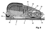
図6は、ヘッド21及びトレイ1の中立位置を示す。好適には隆起部3は、ヘッド21がトレイ1に置かれたときに、ブラシ22、23がブラシ毛と隆起部3の溝型部31、32の凹状面との間の接触に基づいて窪ませられるような形とされ配置される。このことは真空を改善させ、回転するブラシ22、23を備えた掃除装置2が側面から洗浄液を吸い込む能力を向上させる。
FIG. 6 shows the neutral position of the
掃除動作が終了しトレイ1が空となると、掃除装置2はスイッチオフされる。この時点において、ヘッド21は洗浄液により洗われ、ヘッド21の全ての構成要素はその結果洗浄される。図示されたヘッド21の設計においては、ブラシ22、23の上側に配置されたカバー25を開位置にすることが可能であり、それによりブラシ22、23及びその下にあるトレイ1が乾燥し得る。
When the cleaning operation is finished and the
トレイ1及び或る量の洗浄液を用いることによる掃除装置2のヘッド21の洗浄動作は、多くの時間を必要としない。例えば、実際的な場合において、掃除装置2を20秒も動作させるだけで十分となり得ることを試験が示しており、ここで約250mlの洗浄液が使用され得る。ヘッド21の汚れがひどい場合には、ユーザは2回目の洗浄動作を実行させることを決定しても良い。トレイ1が、洗浄液のレベルが数ミリメートルのオーダーにしかならないような形状である場合、好適である。なぜなら、液体を動かし該液体を高いレベルのものよりも低いレベルの隆起部へと供給することが容易になるからである。
The cleaning operation of the
本発明の範囲は以上に議論された例に限定されるものではなく、添付された請求項において定義される本発明の範囲から逸脱することなく、幾つかの変形及び変更が可能であることは、当業者には明らかであろう。本発明は図面及び記述において説明され記載されたが、斯かる説明及び記載は単に説明するもの又は例示的なものであって、限定的なものではないとみなされるべきである。本発明は、開示された実施例に限定されるものではない。 The scope of the invention is not limited to the examples discussed above, and several variations and modifications are possible without departing from the scope of the invention as defined in the appended claims. Will be apparent to those skilled in the art. While the invention has been illustrated and described in the drawings and description, such description and description are to be considered illustrative or exemplary and not restrictive. The invention is not limited to the disclosed embodiments.
図面、説明及び添付される請求項を読むことにより、請求される本発明を実施化する当業者によって、開示された実施例に対する他の変形が理解され実行され得る。請求項において、「有する(comprising)」なる語は他の要素又はステップを除外するものではなく、「1つの(a又はan)」なる不定冠詞は複数を除外するものではない。特定の手段が相互に異なる従属請求項に列挙されているという単なる事実は、これら手段の組み合わせが有利に利用されることができないことを示すものではない。請求項におけるいずれの参照記号も、請求の範囲を限定するものとして解釈されるべきではない。 From reading the drawings, description and appended claims, other variations to the disclosed embodiments can be understood and implemented by those skilled in the art in practicing the claimed invention. In the claims, the word “comprising” does not exclude other elements or steps, and the indefinite article “a” or “an” does not exclude a plurality. The mere fact that certain measures are recited in mutually different dependent claims does not indicate that a combination of these measured cannot be used to advantage. Any reference signs in the claims should not be construed as limiting the claim.
本発明は、極めて柔軟な毛を持つ少なくとも1つのブラシ22、23を有する掃除装置の状況において説明されたが、本発明がこの状況に限定されることを意味するものではないことは理解されるべきである。実際には、本発明は他のタイプの毛を持つブラシにも適用可能である。
Although the present invention has been described in the context of a cleaning device having at least one
掃除装置2は、動作の間にヘッド21において吸引力をかけるように構成されても良いが、このことは必須ではない。斯かる吸引力の下でトレイ1の中に洗浄液の適切な流れを実現することは、本発明を実行する便利な方法であるが、このことは、液体をポンピングして移動させる他の方法も本発明の範囲内であるという事実を変更するものではない。
The
ユーザがトレイ1において不適切にヘッド21を配置してしまうことを防止するための手段を、トレイ1が有することも可能である。ヘッド21の長方形/正方形の形状、及びトレイ1の起立壁12の環状の全体構造13によれば、ユーザが適切な位置から180°逸脱した位置にトレイ1においてヘッド21を置いてしまうリスクが存在する。誤配置を回避するためにとられ得る手段は、トレイ1における突起であって、トレイ1に対するヘッド21の適切な位置においては、該突起がヘッド21に存在する空間において受容され、トレイ1に対するヘッド21の不適切な位置においては、ヘッド21の底部要素が該突起に当接して、ヘッド21がユーザに即座に認知され得るような不安定な位置をとるようにする突起を使用することである。該突起の適切な位置の一例は、ヘッド21がトレイ1における適所に置かれたときに、該突起が2つのブラシ22、23間に正しく延在するような位置である。当該位置は図1において図式的に示されており、ここでは該突起の一例が点線で示され、当該例を示すため参照番号6が使用されている。
The
本発明は、以下のように要約される。少なくとも1つの回転ブラシ22、23により床面を掃除するための掃除装置2が1回以上使用された後、ブラシ22、23が配置された装置2のヘッド21は、ブラシ22、23により拾い上げられた粒子及び/又は液滴により汚され得る。本発明は、ヘッド21と、適切な洗浄動作を保証するように特に適合された起伏を備えたトレイ1と、の洗浄動作を便利に実行するための方法を提供する。ヘッド21の洗浄動作の目的のため、掃除装置2はトレイ1の上に置かれ、トレイ1は或る量の洗浄液で満たされており、掃除装置2は或る時間の間動作させられる。この間、ヘッド21は該洗浄液で洗われ、ここで少なくとも1つのブラシ22、23が、トレイ1から液体を吸い上げ、該液体をヘッド21の構成要素の方向に離すように機能する。本発明によれば、トレイ1は隆起部3を有し、ブラシ22、23は当該部分3において配置され、これによりブラシ22、23が徐々に濡らされ、通常の態様で動作させられることができる。また、隆起部3は、ブラシ22、23を窪ませるために使用され得る。隆起部3に向かう液体の流れを改善するため、トレイ1の最も低い領域37、38が、該液体がブラシ22、23に到達するのに適した位置において、隆起部3の近くに配置される。
The present invention is summarized as follows. After the
Claims (8)
Applications Claiming Priority (3)
| Application Number | Priority Date | Filing Date | Title |
|---|---|---|---|
| EP11153699A EP2484261A1 (en) | 2011-02-08 | 2011-02-08 | Method for cleaning a head of a cleaning device for cleaning surfaces |
| EP11153699.1 | 2011-02-08 | ||
| PCT/IB2012/050543 WO2012107876A1 (en) | 2011-02-08 | 2012-02-07 | Combination of a tray and a cleaning device for cleaning surfaces |
Publications (3)
| Publication Number | Publication Date |
|---|---|
| JP2014507218A JP2014507218A (en) | 2014-03-27 |
| JP2014507218A5 JP2014507218A5 (en) | 2015-03-26 |
| JP6084578B2 true JP6084578B2 (en) | 2017-02-22 |
Family
ID=44147913
Family Applications (1)
| Application Number | Title | Priority Date | Filing Date |
|---|---|---|---|
| JP2013552319A Expired - Fee Related JP6084578B2 (en) | 2011-02-08 | 2012-02-07 | Combination of tray and vacuum cleaner to clean the floor |
Country Status (9)
| Country | Link |
|---|---|
| US (1) | US8819882B2 (en) |
| EP (2) | EP2484261A1 (en) |
| JP (1) | JP6084578B2 (en) |
| CN (1) | CN103369996B (en) |
| BR (1) | BR112013019894A2 (en) |
| PL (1) | PL2672872T3 (en) |
| RU (1) | RU2579911C2 (en) |
| TR (1) | TR201908946T4 (en) |
| WO (1) | WO2012107876A1 (en) |
Families Citing this family (24)
| Publication number | Priority date | Publication date | Assignee | Title |
|---|---|---|---|---|
| DE102015108534A1 (en) * | 2015-05-29 | 2016-12-01 | Vorwerk & Co. Interholding Gmbh | Cleaning device with a cleaning roller |
| US9357891B1 (en) * | 2015-08-04 | 2016-06-07 | Richard C. Chappel | Cleaning apparatus holder |
| AU2016101847B4 (en) | 2015-10-28 | 2022-02-17 | Bissell Inc. | Surface cleaning apparatus |
| USD809232S1 (en) * | 2016-05-20 | 2018-01-30 | Bissell Homecare, Inc. | Combined tray and brush holder for a surface cleaning apparatus |
| DE102016111809A1 (en) * | 2016-06-28 | 2017-12-28 | Vorwerk & Co. Interholding Gmbh | Wet cleaning device with a cleaning roller rotatably mounted about a roll axis |
| DE102016114415A1 (en) * | 2016-08-04 | 2018-02-08 | Vorwerk & Co. Interholding Gmbh | Wet cleaning device with a cleaning roller |
| AU2018203547B2 (en) | 2017-06-02 | 2023-09-28 | Bissell Inc. | Self-cleaning system and method for extraction cleaners |
| CN110786791A (en) * | 2018-08-02 | 2020-02-14 | 添可智能科技有限公司 | Surface cleaning machine, roller brush cover and cleaning support cover |
| AU2019327392B2 (en) | 2018-08-27 | 2022-03-03 | Techtronic Floor Care Technology Limited | Floor cleaner |
| WO2020132482A1 (en) | 2018-12-21 | 2020-06-25 | Tennant Company | Sweeper/scrubber system capable of handling large debris |
| US11304581B2 (en) | 2019-01-08 | 2022-04-19 | Bissell Inc. | Surface cleaning apparatus |
| AU2020100233A4 (en) | 2019-02-26 | 2020-03-26 | Bissell Inc. | Surface cleaning apparatus with drying cycle |
| AU2020245387B2 (en) | 2019-03-28 | 2023-06-01 | Techtronic Cordless Gp | Floor cleaner and tray |
| CN111358391B (en) * | 2019-11-21 | 2022-06-03 | 添可智能科技有限公司 | Cleaning tray and cleaning machine assembly |
| DE102019112779B3 (en) * | 2019-05-15 | 2020-10-15 | Carl Freudenberg Kg | Cleaning device for cleaning a rotatable roller brush of a cleaning device and cleaning system |
| CN114568998A (en) * | 2020-02-17 | 2022-06-03 | 添可智能科技有限公司 | Self-cleaning control method of cleaning equipment and cleaning equipment |
| DE102020114451A1 (en) | 2020-05-29 | 2021-12-02 | Carl Freudenberg Kg | Cleaning device for cleaning a mechanical cleaning arrangement of a cleaning device and cleaning system |
| EP4059398A1 (en) | 2021-03-17 | 2022-09-21 | Koninklijke Philips N.V. | Supplying liquid to at least one wheel of a suction head |
| EP4059399A1 (en) | 2021-03-17 | 2022-09-21 | Koninklijke Philips N.V. | Supplying liquid to at least one area of a surface to be cleaned |
| EP4059405A1 (en) | 2021-03-17 | 2022-09-21 | Koninklijke Philips N.V. | Suction head for application in a vacuum cleaner |
| EP4059397A1 (en) | 2021-03-17 | 2022-09-21 | Koninklijke Philips N.V. | Transport of dirt in a suction head for use in a vacuum cleaner |
| CN113180553B (en) * | 2021-04-21 | 2022-04-05 | 尚科宁家(中国)科技有限公司 | Cleaning method of surface cleaning device |
| EP4091513A1 (en) * | 2021-05-19 | 2022-11-23 | Koninklijke Philips N.V. | Wet floor cleaner |
| EP4094659A1 (en) | 2021-05-26 | 2022-11-30 | Koninklijke Philips N.V. | Wet vacuum cleaner, a cleaning tray and a cleaning method |
Family Cites Families (11)
| Publication number | Priority date | Publication date | Assignee | Title |
|---|---|---|---|---|
| JPH045940A (en) * | 1990-04-23 | 1992-01-09 | Mitsubishi Electric Home Appliance Co Ltd | Containing device for vacuum cleaner |
| US5640738A (en) * | 1995-08-02 | 1997-06-24 | Williams; William H. | Wet and dry vacuum cleaner |
| US5920939A (en) * | 1997-07-23 | 1999-07-13 | Firma Fedag | Floor cleaning apparatus having a rotating brush roller |
| US6766556B2 (en) * | 2001-03-13 | 2004-07-27 | Franc Gergek | Apparatus for cleaning surfaces with automatic water supply and drain |
| US7152267B2 (en) * | 2003-09-25 | 2006-12-26 | Bryan Kaleta | Floor sweeper |
| JP4133853B2 (en) * | 2004-01-30 | 2008-08-13 | シャープ株式会社 | Self-propelled vacuum cleaner |
| US7987552B2 (en) * | 2004-11-17 | 2011-08-02 | Techtronic Floor Care Technology Limited | Floor care appliance with a plurality of cleaning modes |
| US8087117B2 (en) * | 2006-05-19 | 2012-01-03 | Irobot Corporation | Cleaning robot roller processing |
| DE102007029258A1 (en) * | 2007-06-15 | 2008-12-18 | Alfred Kärcher Gmbh & Co. Kg | Floor cleaning device |
| CN101524260A (en) * | 2008-03-03 | 2009-09-09 | 麦晓明 | Intelligent mopping robot |
| FR2942710A1 (en) * | 2009-03-04 | 2010-09-10 | Ayoun Jackie Daniele Szerman | Small and average surfaces/access difficult places cleaning apparatus for e.g. dry floor, has wheel devices placed, so that blocking is made to actuate semi-axles, and brushes integrated in direction of rotation towards recovery device |
-
2011
- 2011-02-08 EP EP11153699A patent/EP2484261A1/en not_active Withdrawn
-
2012
- 2012-02-07 CN CN201280008075.3A patent/CN103369996B/en active Active
- 2012-02-07 RU RU2013141168/12A patent/RU2579911C2/en active
- 2012-02-07 WO PCT/IB2012/050543 patent/WO2012107876A1/en active Application Filing
- 2012-02-07 JP JP2013552319A patent/JP6084578B2/en not_active Expired - Fee Related
- 2012-02-07 BR BR112013019894A patent/BR112013019894A2/en not_active IP Right Cessation
- 2012-02-07 US US13/982,840 patent/US8819882B2/en active Active
- 2012-02-07 PL PL12704331T patent/PL2672872T3/en unknown
- 2012-02-07 EP EP12704331.3A patent/EP2672872B1/en active Active
- 2012-02-07 TR TR2019/08946T patent/TR201908946T4/en unknown
Also Published As
| Publication number | Publication date |
|---|---|
| US8819882B2 (en) | 2014-09-02 |
| BR112013019894A2 (en) | 2016-10-11 |
| TR201908946T4 (en) | 2019-07-22 |
| CN103369996A (en) | 2013-10-23 |
| JP2014507218A (en) | 2014-03-27 |
| EP2672872A1 (en) | 2013-12-18 |
| RU2579911C2 (en) | 2016-04-10 |
| PL2672872T3 (en) | 2019-10-31 |
| RU2013141168A (en) | 2015-03-20 |
| CN103369996B (en) | 2017-03-08 |
| WO2012107876A1 (en) | 2012-08-16 |
| US20130305468A1 (en) | 2013-11-21 |
| EP2672872B1 (en) | 2019-04-10 |
| EP2484261A1 (en) | 2012-08-08 |
Similar Documents
| Publication | Publication Date | Title |
|---|---|---|
| JP6084578B2 (en) | Combination of tray and vacuum cleaner to clean the floor | |
| RU2511487C2 (en) | Device and method of wet cleaning of floors | |
| EP2747625B1 (en) | Cleaning device for cleaning a surface comprising a brush and a squeegee element | |
| US4344201A (en) | Cleaning apparatus | |
| ES2813173T3 (en) | Wet cleaning device with a rotating cleaning roller | |
| CN103068292B (en) | For the cleaning device cleaning mop material and the method cleaning mop material | |
| CN105517472B (en) | Surface cleaning apparatus | |
| US10188250B2 (en) | Floor cleaning tool having a mechanically operated pump | |
| US9615710B2 (en) | Floor care device for applying a floor care fluid | |
| JP2019523051A (en) | Wet vacuum cleaner with cleaning roller | |
| JP6432031B2 (en) | Wet cleaning device, especially window cleaning device | |
| US4464809A (en) | Cleaning apparatus | |
| JP2015536228A (en) | Mop bucket with flat platform | |
| CN213155704U (en) | Cleaning device for mopping equipment | |
| US4506403A (en) | Cleaning apparatus | |
| CN218356067U (en) | Move liquid spare and cleaner system thereof | |
| CN218870144U (en) | Suction head and cordless vacuum cleaner | |
| CN115104973B (en) | Floor cleaning system | |
| KR101750725B1 (en) | Robotic vaccum cleaner with water jet module | |
| KR101565888B1 (en) | Floor cleaner capable of collecting wasted liquid | |
| KR200401003Y1 (en) | Movable handy cleaner | |
| AU2021391424A1 (en) | Surface cleaner | |
| CN117042661A (en) | Delivery of dirt in a suction head for use in a vacuum cleaner | |
| GB2523182A (en) | A bucket, combination including a bucket insert, and a method |
Legal Events
| Date | Code | Title | Description |
|---|---|---|---|
| A521 | Written amendment |
Free format text: JAPANESE INTERMEDIATE CODE: A523 Effective date: 20150204 |
|
| A621 | Written request for application examination |
Free format text: JAPANESE INTERMEDIATE CODE: A621 Effective date: 20150204 |
|
| A977 | Report on retrieval |
Free format text: JAPANESE INTERMEDIATE CODE: A971007 Effective date: 20150722 |
|
| A131 | Notification of reasons for refusal |
Free format text: JAPANESE INTERMEDIATE CODE: A131 Effective date: 20150813 |
|
| A601 | Written request for extension of time |
Free format text: JAPANESE INTERMEDIATE CODE: A601 Effective date: 20151104 |
|
| A02 | Decision of refusal |
Free format text: JAPANESE INTERMEDIATE CODE: A02 Effective date: 20160630 |
|
| A521 | Written amendment |
Free format text: JAPANESE INTERMEDIATE CODE: A523 Effective date: 20161014 |
|
| A911 | Transfer of reconsideration by examiner before appeal (zenchi) |
Free format text: JAPANESE INTERMEDIATE CODE: A911 Effective date: 20161025 |
|
| TRDD | Decision of grant or rejection written | ||
| A01 | Written decision to grant a patent or to grant a registration (utility model) |
Free format text: JAPANESE INTERMEDIATE CODE: A01 Effective date: 20170105 |
|
| A61 | First payment of annual fees (during grant procedure) |
Free format text: JAPANESE INTERMEDIATE CODE: A61 Effective date: 20170125 |
|
| R150 | Certificate of patent or registration of utility model |
Ref document number: 6084578 Country of ref document: JP Free format text: JAPANESE INTERMEDIATE CODE: R150 |
|
| LAPS | Cancellation because of no payment of annual fees |