EP4094659A1 - Wet vacuum cleaner, a cleaning tray and a cleaning method - Google Patents
Wet vacuum cleaner, a cleaning tray and a cleaning method Download PDFInfo
- Publication number
- EP4094659A1 EP4094659A1 EP21175995.6A EP21175995A EP4094659A1 EP 4094659 A1 EP4094659 A1 EP 4094659A1 EP 21175995 A EP21175995 A EP 21175995A EP 4094659 A1 EP4094659 A1 EP 4094659A1
- Authority
- EP
- European Patent Office
- Prior art keywords
- cleaning
- brush
- suction
- tray
- head
- Prior art date
- Legal status (The legal status is an assumption and is not a legal conclusion. Google has not performed a legal analysis and makes no representation as to the accuracy of the status listed.)
- Withdrawn
Links
- 238000004140 cleaning Methods 0.000 title claims abstract description 228
- 238000000034 method Methods 0.000 title claims abstract description 19
- 239000007788 liquid Substances 0.000 claims abstract description 71
- 238000011144 upstream manufacturing Methods 0.000 claims abstract description 21
- 238000002791 soaking Methods 0.000 abstract description 4
- XLYOFNOQVPJJNP-UHFFFAOYSA-N water Substances O XLYOFNOQVPJJNP-UHFFFAOYSA-N 0.000 description 23
- 239000003570 air Substances 0.000 description 4
- 230000000694 effects Effects 0.000 description 4
- 230000033001 locomotion Effects 0.000 description 4
- 238000009987 spinning Methods 0.000 description 4
- 230000007480 spreading Effects 0.000 description 4
- 230000008859 change Effects 0.000 description 3
- 239000012530 fluid Substances 0.000 description 3
- 239000012080 ambient air Substances 0.000 description 2
- 230000004888 barrier function Effects 0.000 description 2
- 230000008901 benefit Effects 0.000 description 2
- 238000007373 indentation Methods 0.000 description 2
- 240000002791 Brassica napus Species 0.000 description 1
- 241000826860 Trapezium Species 0.000 description 1
- 230000009471 action Effects 0.000 description 1
- 230000001580 bacterial effect Effects 0.000 description 1
- 238000007664 blowing Methods 0.000 description 1
- 239000012459 cleaning agent Substances 0.000 description 1
- 230000003749 cleanliness Effects 0.000 description 1
- 230000001419 dependent effect Effects 0.000 description 1
- 239000002657 fibrous material Substances 0.000 description 1
- 235000019645 odor Nutrition 0.000 description 1
- 239000002245 particle Substances 0.000 description 1
- 230000000630 rising effect Effects 0.000 description 1
- 238000005201 scrubbing Methods 0.000 description 1
- 230000007704 transition Effects 0.000 description 1
- 238000010407 vacuum cleaning Methods 0.000 description 1
Images
Classifications
-
- A—HUMAN NECESSITIES
- A46—BRUSHWARE
- A46B—BRUSHES
- A46B17/00—Accessories for brushes
- A46B17/06—Devices for cleaning brushes after use
-
- A—HUMAN NECESSITIES
- A47—FURNITURE; DOMESTIC ARTICLES OR APPLIANCES; COFFEE MILLS; SPICE MILLS; SUCTION CLEANERS IN GENERAL
- A47L—DOMESTIC WASHING OR CLEANING; SUCTION CLEANERS IN GENERAL
- A47L9/00—Details or accessories of suction cleaners, e.g. mechanical means for controlling the suction or for effecting pulsating action; Storing devices specially adapted to suction cleaners or parts thereof; Carrying-vehicles specially adapted for suction cleaners
- A47L9/02—Nozzles
- A47L9/04—Nozzles with driven brushes or agitators
- A47L9/0461—Dust-loosening tools, e.g. agitators, brushes
- A47L9/0466—Rotating tools
- A47L9/0477—Rolls
Definitions
- This invention relates to a wet vacuum cleaner, in particular it relates to the cleaning of roller brushes used in the head of a wet vacuum cleaner.
- wet vacuum cleaners are known in which the cleaning head (often known as the "nozzle") has two counter-rotating brushes. Suction is applied at least to the space between the brushes to draw up liquid from the floor that has been delivered to the floor by the vacuum cleaner. The brushes contact the floor to perform a scrubbing action.
- Wet vacuum cleaners are hard to clean after use. Cleaning after use is a prerequisite to avoid bacterial growth and unpleasant odors after use. The user perceives both as unhygienic.
- EP2672872 discloses a tray to clean the roller brush of a wet vacuum cleaner.
- a cleaning tray of a wet floor cleaner adapted to receive a head of the wet floor cleaner, the head comprising a roller brush, the cleaning tray comprising:
- This cleaning tray has at least one brush channel to receive a roller brush.
- the turbulence provides improved mixing of debris with cleaning liquid so that debris can be more effectively removed during a cleaning cycle when using the cleaning tray.
- the rotation of the roller brush creates an under pressure at the location of the downstream ramp surface, thereby drawing cleaning liquid towards it. This enables the efficient transport of the cleaning liquid within the tray, in particular so that the whole of the roller brush (as well as the whole area of the cleaning tray) is subjected to a cleaning liquid flow in use.
- the under pressure is enhanced because the outer circumference of the roller brush may not make contact with the downstream ramp surface due to the rotational speed, and the inertia of the tufts, preventing them from immediately deforming radially outwardly to the location of the downstream ramp surface. Thus, a cavity is formed behind the downstream ramp surface, creating under pressure.
- upstream and downstream relate to the rotation of the roller brush, i.e. a rotating roller brush circumference meets the upstream surface first.
- the upstream ramp surface is preferably a smooth ramp. It may be straight or concave or convex, or may have multiple sections each of different convex, concave or straight shape. It does not present a barrier to cleaning liquid flow and hence does not block the passage of cleaning liquid being carried by the roller brush, but provides a guide surface. The transition between the upstream and downstream ramp surfaces in particular introduces the turbulence.
- the cleaning tray for example comprises a set of raised projections each having an upstream ramp surface and a downstream ramp surface.
- the use of multiple raised projections enables the cleaning liquid flow around the roller brush and the cleaning tray to be controlled to ensure cleaning of the entire surface of the roller brush, by preventing the collection of cleaning liquid (which is for example delivered by the head of the wet floor cleaner) only in localized areas of the roller brush.
- The, or each, raised projection for example has:
- This height is measured from the bottom of the brush channel. Even a relatively small projection is able to create sufficient turbulence to improve the collection of debris from the roller brush during cleaning.
- The, or each, raised projection for example has an apex at the junction between the upstream and downstream ramp surfaces, with an angle of 90 degrees or more.
- the apex for example has a radius of curvature of less than 2mm.
- a sharp corner creates a sudden change in the flow area, thereby introducing significant turbulence to the flow.
- the brush channel may comprise a set of two or more raised projections.
- the projections may be distributed along the length of the roller brush, for example including near the ends, to provide a turbulent cleaning effect along their length.
- the brush channel for example comprises a set of two or more raised projections, wherein there are at least two different shapes of raised projection within the set.
- Using different designs of projection enables the desired flow patterns to be controlled more accurately.
- Different shapes of projections may have different width and/or height.
- the cleaning tray may further comprise, in the brush channel, a flow guide which provides a flow path across the brush channel to the suction area.
- the flow guide provides additional control of the cleaning liquid flow around the tray and in particular it assists in steering the cleaning liquid to the corners of the tray when there is a large amount of cleaning liquid present. At the end of a cleaning cycle, when there is a small amount of cleaning liquid, it also assists in directing the remaining amount of cleaning liquid to the center of the tray where the cleaning liquid will be picked up by a suction airflow. Thus, the flow guide further assists in obtaining a clean and dry tray.
- the flow guide for example comprises two lateral side projections which become closer together along the flow path.
- the flow guide defines a narrowing channel towards the suction area.
- the side projections for example have a height in the range 1mm to 6mm.
- the two lateral side projections for example form part of a V-shape with an apex angle in the range 40 to 120 degrees.
- the cleaning tray may comprise opposite side walls, wherein one of the side walls has an openings (or pair of openings) through which the roller brush (or both roller brushes) may be received laterally parallel to their axes of rotation.
- roller brush or brushes
- the roller brush may then be exposed to ambient air to dry fully, and the openings also allow air flow around the cleaning head to dry fully.
- the cleaning tray is for example adapted to receive a head of a wet floor cleaner which comprises a pair of roller brushes, wherein the cleaning tray comprises a pair of brush channels, and the suction areas is between the pair of brush channels.
- the invention also provides a wet floor cleaner comprising:
- the delivery system may be a second pump which is part of the cleaner, or there may be a separate external fluid supply. In the latter case, the delivery system is a conduit for receiving cleaning liquid from the external fluid supply and routing it to the cleaning head.
- the cleaning head for example further comprises a support wheel arrangement for mounting the housing at a minimum spacing over the floor to be cleaned.
- a drive arrangement is also provided for driving the first and second rotary brushes in opposite rotation directions.
- the invention also provides a method of cleaning a roller brush of a cleaning head of a wet floor cleaner, when the cleaning head is fitted to a cleaning tray, the cleaning head comprising at least one rotary brush and suction channel for delivering suction to at least a space adjacent the at least one rotary brush, the method comprising:
- the terms “relatively large”, “relatively small”, “relatively slow” and “relatively fast” refer to the individual cycles.
- the “relatively large volume” in the middle cycle does not have to be the same “relatively large volume” as used in the start cycle. It only needs to be larger than the “relatively small volume” of the middle cycle.
- This method provides a three cycle cleaning method.
- the first cycle uses low speed rotation and a large amount of cleaning liquid (e.g. water) to soak the brush.
- a large suction and high roller drive speed is used to remove the residue without spreading dirt in the tray. This may be thought of as a pre-wash which removes coarse dirt.
- the middle cycle has a spinning period with no suction and only a small amount of cleaning liquid, to spin dirt out from the brush.
- the end cycle delivers the most cleaning liquid to provide soaking and to reach every area of the cleaning tray at low brush speed. This may be thought of as a rinse cycle.
- the cleaning liquid is then removed by applying suction.
- This cleaning method has been found to be particularly effective and enables operation with low power.
- the middle cycle may be applied twice or even more than twice.
- the last step of the end cycle may comprise driving the roller brush at a relatively fast rotational speed and applying the second level of suction and then the first level of suction with no delivered cleaning liquid.
- the method is for example applied with the cleaning head fitted to a cleaning tray as defined above.
- the invention provides a cleaning tray for a wet floor cleaner, for receiving a head of the wet floor cleaner.
- the cleaning tray has at least one brush channel for receiving a bottom portion of an outer circumference of a roller brush.
- At least one raised projection is positioned along the brush channel having an upstream ramp surface and a steeper downstream ramp surface. The projection adds turbulence for improving the cleaning results as well as enabling control of the flow of cleaning liquid around the brush and the cleaning tray, to ensure full soaking of the brush as well as cleaning of all of the area of the cleaning tray itself.
- the invention also provides a cleaning method which may use the cleaning tray.
- the invention thus relates to a cleaning tray for cleaning the head of a wet floor cleaner.
- the general configuration of the cleaner head will first be explained, for a particular example with a pair of parallel roller brushes.
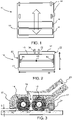
- Figure 1 shows a known layout for a wet floor cleaner head 10, viewed from the underside.
- the head comprises a housing 12 which supports a first, front brush 14 and a second, rear brush 16.
- a set of four support wheels 18 is arranged in a rectangular configuration behind the rear brush 16.
- a main direction of motion of the cleaning head in use is parallel to a length direction of the cleaning head, perpendicular to the width direction of the housing as defined above.
- the main direction of movement is shown by the large arrow. This motion tends to roll the brushes over the floor.
- Figure 2 shows another known layout to achieve a smaller and more compact cleaning head, for example more suitable for a battery-operated device.
- the head 10 again comprises a housing 12 which supports a first, front brush 14 and a second, rear, brush 16.
- the housing 12 has width W between first and second side walls 20, 22 and a length L, the length being parallel to the intended main direction of movement of the cleaning head over a floor to be cleaned.
- the first and second rotary brushes 14, 16 each extend across the width of the housing between the first and second side walls 20, 22, with parallel rotation axes, and side by side in the length direction.
- a suction channel is provided for delivering suction to at least a space 24 between the first and second rotary brushes 14, 16. The suction is applied to the general volume of the housing.
- the support wheel arrangement in this design comprises a first support wheel 30 in the space 24 between the first and second rotary brushes and a second support wheel 32 in the space 24 between the first and second rotary brushes.
- the outer faces of the wheels are approximately flush with the side walls.
- first and second support wheels between the rotary brushes saves space.
- Figure 3 shows a cross section though one 34 of the rear support wheels 34,36 of the cleaning head of Figure 2 , and shows the support wheel 30 further back (behind the plane of the cross section). It shows that the first and second rotary brushes 14, 16 are driven in opposite rotation directions, so that they move upwardly where they face each other, in the space 24.
- a suction channel 40 delivers suction to at least the space 24 between the first and second rotary brushes.
- the rotary brushes are driven by a drive arrangement which may comprise a single motor and a belt drive for driving the two rotary brushes.
- a drive arrangement which may comprise a single motor and a belt drive for driving the two rotary brushes.
- each rotary brush may have its own respective motor mounted in the core of the respective rotary brush.
- the cleaning head also has a fluid delivery arrangement (not shown) for delivering cleaning liquid (i.e. water and optionally cleaning agents) to the first and/or second rotary brushes.
- Cleaning liquid may for example be delivered to the rotary brush 16 at the back of the cleaning head from a reservoir formed in a main housing of the vacuum cleaner.
- the vacuum cleaner itself has a first pump (fan) for delivering suction to the cleaning head and a second pump for delivering the cleaning liquid.
- the mounting of the support wheels by the housing defines a minimum spacing S between a bottom surface of the housing and the floor surface.
- This minimum spacing is for example in the range 1.5 mm to 3 mm.
- the rotary brushes project below the level of the floor (when the floor is not present) so that the tufts are deformed by the presence of the floor. This defines a floor indentation and it is part of the water gathering and cleaning function as well as providing brush torque control.
- Figure 3 also shows front and rear spoilers 42 which keep air pressure inside the housing to prevent air and water blowing out of the system, making it hard to pick up dirt from the floor. They also guide water which has been sprayed against the housing back to the brushes.
- This invention relates in particular to a design of the cleaning tray to achieve optimum cleaning of the brushes, as well as to a cleaning cycle. By making the cleaning cycle more effective, it can be performed with lower power, which is of particular interest for a battery-operated vacuum cleaner.
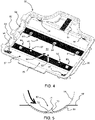
- Figure 4 shows a cleaning tray 50 for a wet floor cleaner, for receiving a head 10 of the wet floor cleaner.
- the cleaning tray comprises a base 52 for supporting the head.
- Mounting areas 54 are provided for engaging with the cleaning head to provide a reliable positioning of the cleaning head in the cleaning tray.
- the cleaning tray 50 comprises a pair of brush channels 56 formed in the base. These comprise an arcuate indentation (with a cylindrical shape corresponding almost to the cylindrical shape of the outer circumference of the roller brushes). In use, the outer circumference of the roller brushes contacts the brush channels to provide deformation of the tufts and hence promote cleaning.
- the radius of the brush channel is for example smaller than the outer radius of the roller brush by an amount in the range 1mm to 3mm.
- each brush channel is for receiving a bottom portion of an outer circumference of a respective roller brush.
- suction area 58 between the brush channels 56, and a suction nozzle of the cleaning head, when positioned in the cleaning tray, is located over this suction area.
- the invention provides a raised projection in one or both of the brush channels.
- One raised projection is sufficient to have a significant effect on the cleaning liquid flow during cleaning.
- Figure 4 shows an example with six projections, of two different designs.
- a front brush channel has two larger projections 60 near the ends and two smaller projections 62 located more centrally.
- a rear brush channel has two larger projections 64 near the ends as well as one in the middle.
- the projections at the ends of the brush channels have more effect when the cleaning tray is full of water. As water is removed, the projections at the ends of the brush channels have a reduced function as there is no longer any water away from the center. Thus, the more central projections then continue to introduce turbulence (as explained below) until all the water has been removed.
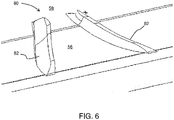
- Figure 5 shows one projection 60 in more detail in cross section perpendicular to the length axis of the brush channel 56.
- the depth of the brush channel is for example 3mm or less.
- the projection 60 is for projecting into the tufts of roller brush when the cleaning tray is used, as can be seen by the brush 14 in Figure 5 .
- the raised projection comprises an upstream ramp surface 70 positioned such that the outer circumference of the roller brush 14 rides up the upstream ramp surface when rotated.
- the upstream ramp surface is smooth so presents a gradual decrease in available radius for the roller brush rather than an abrupt face. However, it may be straight, concave or convex or have different sections with different curvature.
- a downstream ramp surface 72 is steeper than the upstream ramp surface.
- the downstream ramp surface faces the suction area 58.
- the upstream ramp surface for example has an angle in the range 20 to 40 degrees (relative to a straight line between the back and front of the projection where is meets the brush channel) and the downstream ramp surface for example has an angle in the range 60 to 90 degrees.
- Each ramp surface may be approximated as a straight plane between the apex and the front or back, for this purposes of this angle definition.
- the projections function as turbulence introducing elements.
- the turbulence provides improves mixing of debris with liquid so that debris can be more effectively removed during a cleaning cycle.
- the rotation of the roller brushes creates an under pressure at the location of (downstream of) the downstream ramp surface, thereby drawing cleaning liquid towards it. This enables the efficient transport of the cleaning liquid within the tray, in particular so that the whole of the roller brush is subjected to a cleaning liquid flow in use.
- the under pressure is enhanced as the outer circumference of the roller brush may not make contact with the downstream ramp surface due to the rotational speed, and the inertia of the tufts preventing them from immediately deforming radially outwardly to meet the downstream ramp surface.
- the turbulence and under pressure create a flow of water borne particles circulating in the tray.
- the projections for example have a height (in a radial direction of the roller brushes) in the range 1mm to 10mm; and/or a length, parallel to a length of the brush channels, in the range 1mm to 50mm.
- a relatively small projection is able to create sufficient turbulence to improve the collection of debris from the roller brushes during cleaning.
- the apex 74 for example has an angle of 90 degrees or more. This gives a rapid change in direction of the surface over which the roller brushes are driven and thereby creates the desired turbulence and under pressure.
- the apex 74 for example has a radius of curvature of less than 2mm.
- the projections are for example formed as an integral part of the tray.
- the pressure differences created by the ramp surfaces are designed to control the cleaning liquid flow to spread the cleaning liquid along the length of the brushes.
- the projections near the corners of the tray are positioned on the two sides of the wheels, and in this way they provide protection for the area near the wheels.
- This area is very sensitive to pollution of mainly fibrous material that easily raps around the shafts of the wheels.
- the projections reduce this pollution by providing a barrier function and creating turbulence near the wheels.
- the front brush channel 56 additionally has a flow guide 80 which provides a flow path across the brush channel 56 to the suction area 58.
- the flow guide provides additional control of the cleaning liquid flow around the tray. In particular, it assists in steering the cleaning liquid to the corners of the tray when there is a large amount of cleaning liquid present. At the end of a cleaning cycle it also assists in directing the reduced amount of cleaning liquid to the center of the tray where the cleaning liquid will be picked up by the suction flow. Thus, the flow guide further 80 assists in obtaining a clean and almost dry tray.
- the flow guide 80 comprises two lateral side projections 82 which become closer together along the flow path towards the suction area 58.
- the side projections 82 for example have a height in the range 1mm to 6mm. They form part of a V-shape with an apex angle in the range 40 to 120 degrees.
- Figure 6 shows the flow guide 80 more clearly.
- Figure 4 also shows that the cleaning tray has opposite side walls 90, 92.
- One of the side walls 92 has a pair of openings 94 through which the roller brushes may be received laterally parallel to their axes of rotation.
- roller brushes This enables removal of the brushes from the cleaning head and then from the cleaning tray, after cleaning has finished but with the cleaning head remaining in the cleaning tray.
- the roller brushes may then be exposed to ambient air to dry fully, and the openings then also allow air flow around the cleaning head to dry fully.
- the invention also provides a method of using the cleaning tray.
- the method comprises three types of cycle.
- the cycle characteristics are shown in the table below. Cycle 1 is a start cycle, cycles 2 and 3 are middle cycles and cycle 4 is an end cycle. Each cycle has multiple steps.
- Each step involves a rotational speed for the roller brushes (“RPM”), a suction power (“Fan Power”), a cleaning liquid delivery rate (“Pump rate”), and a duration ("Time”).
- RPM rotational speed for the roller brushes
- Fluction power Fluction power
- Flup rate cleaning liquid delivery rate
- Time time
- the product of the duration and cleaning liquid delivery rate gives the amount of cleaning liquid used ("Water vol.”).
- the start cycle involves:
- the middle cycle involves:
- the end cycle involves:
- This step fills the tray with enough cleaning liquid to soak at a low RPM but without water spitting out to sides and front.
- a vacuum is applied for a high airflow and the brushes spin at a high RPM at the same time, to remove all course dirt without spreading dirt in tray.
- the tray is filled with enough water to soak at low brush RPM and create turbulence releasing dirt from the corners and edges.
- the brushes are spun at high RPM thereby spinning out dirt from the brushes and rising the tray (and a viewing window).
- step 3 This is a repetition of step 3, to fill with enough water to soak the brushes and at a low brush RPM, thereby creating turbulence releasing dirt from the corners and edges.
- step 4 This is a repetition of step 4, to spin at high brush RPM thereby spinning out dirt from the brush and rinsing the tray and window.
- step 5 This is a repetition of step 5, to vacuum dirty water from the tray with low airflow.
- This step involves over-filling the tray with water to soak at low RPM. Turbulence is created in every corner of the tray and nozzle to release any remaining dirt.
- a vacuum is applied at low airflow with a high roller brush RPM to remove most water and dirt, without spitting the additional filled water out of the tray by the raised RPM.
- a vacuum is applied for a high airflow with a high roller brush RPM to remove all remaining water and dirt.
- the method provides a three cycle cleaning method (with the middle cycle repeated with slightly different timing).
- the first cycle uses low speed rotation and a large amount of cleaning liquid to soak the brushes.
- a large suction and high roller drive speed is used to remove the residue without spreading dirt in the tray. This may be thought of as a pre-wash which removes coarse dirt.
- the middle cycle has a spinning period with no suction and only a small amount of cleaning liquid, to spin dirt out from the brushes.
- the end cycle delivers the most cleaning liquid to provide soaking and to reach every area of the cleaning tray at low brush speed. This may be thought of as a rinse cycle.
- the cleaning liquid is then removed by applying suction and with a high brush rotation speed.
- the housing of the cleaning head is shown as generally rectangular so that the side walls 20, 22 are parallel, but the side walls may be non-parallel for example with a triangular or trapezium shaped housing.
- the first and second brushes may have the same length (in the width direction of the head) or they may have different lengths.
- the cleaning tray is designed to match the cleaning head.
- the example above has a pair of roller brushes.
- the invention may be applied to a cleaning head with a single roller brush, for example a roller brush in front of a squeegee.
- the function of the projection or projections in spreading water along the length of the roller brush as well as the flow control achieved is applicable also to cleaning of a cleaning head with a single roller brush.
Abstract
The invention provides a cleaning tray for a wet floor cleaner, for receiving a head of the wet floor cleaner. The cleaning tray has at least one brush channels for receiving a bottom portion of an outer circumference of a roller brush. At least one raised projection is positioned along the brush channel having an upstream ramp surface and a steeper downstream ramp surface. The projection adds turbulence for improving the cleaning results as well as enabling control of the flow of cleaning liquid around the brush and the cleaning tray, to ensure full soaking of the brush as well as cleaning of all of the area of the cleaning tray itself. The invention also provides a cleaning method which may use the cleaning tray.
Description
- This invention relates to a wet vacuum cleaner, in particular it relates to the cleaning of roller brushes used in the head of a wet vacuum cleaner.
- Wet vacuum cleaners are known in which the cleaning head (often known as the "nozzle") has two counter-rotating brushes. Suction is applied at least to the space between the brushes to draw up liquid from the floor that has been delivered to the floor by the vacuum cleaner. The brushes contact the floor to perform a scrubbing action.
- Wet vacuum cleaners are hard to clean after use. Cleaning after use is a prerequisite to avoid bacterial growth and unpleasant odors after use. The user perceives both as unhygienic.
- To overcome this problem some wet vacuum cleaners are equipped with a cleaning tray that is used to rinse the appliance after use. For example,
EP2672872 discloses a tray to clean the roller brush of a wet vacuum cleaner. - Most known wet vacuum cleaners are connected to mains power. In battery driven appliances, the known use of a tray would not work well because the available suction power is not sufficient to achieve an acceptable cleaning result.
- There is therefore a need for an improved wet vacuum cleaning tray, in particular that can be used for a battery-driven appliance. There is also a need for an improved cleaning result of the appliance as well as from the tray.
- The invention is defined by the claims.
- According to examples in accordance with an aspect of the invention, there is provided a cleaning tray of a wet floor cleaner, adapted to receive a head of the wet floor cleaner, the head comprising a roller brush, the cleaning tray comprising:
- a base for supporting the head;
- a brush channel formed in the base for receiving a bottom portion of an outer circumference of the roller brush;
- at least one raised projection positioned along the brush channel which is for projecting into the roller brush when the cleaning tray is used, wherein the raised projection comprises an upstream ramp surface positioned such that the outer circumference of the roller brush rides up the upstream ramp surface when rotated and a downstream ramp surface, wherein the downstream ramp surface is steeper than the upstream ramp surface; and
- a suction area faced by the downstream ramp surface.
- This cleaning tray has at least one brush channel to receive a roller brush. There is at least one projection which functions as a turbulence introducing element. The turbulence provides improved mixing of debris with cleaning liquid so that debris can be more effectively removed during a cleaning cycle when using the cleaning tray. The rotation of the roller brush creates an under pressure at the location of the downstream ramp surface, thereby drawing cleaning liquid towards it. This enables the efficient transport of the cleaning liquid within the tray, in particular so that the whole of the roller brush (as well as the whole area of the cleaning tray) is subjected to a cleaning liquid flow in use. The under pressure is enhanced because the outer circumference of the roller brush may not make contact with the downstream ramp surface due to the rotational speed, and the inertia of the tufts, preventing them from immediately deforming radially outwardly to the location of the downstream ramp surface. Thus, a cavity is formed behind the downstream ramp surface, creating under pressure.
- Note that "upstream" and "downstream" relate to the rotation of the roller brush, i.e. a rotating roller brush circumference meets the upstream surface first.
- The upstream ramp surface is preferably a smooth ramp. It may be straight or concave or convex, or may have multiple sections each of different convex, concave or straight shape. It does not present a barrier to cleaning liquid flow and hence does not block the passage of cleaning liquid being carried by the roller brush, but provides a guide surface. The transition between the upstream and downstream ramp surfaces in particular introduces the turbulence.
- The cleaning tray for example comprises a set of raised projections each having an upstream ramp surface and a downstream ramp surface.
- The use of multiple raised projections enables the cleaning liquid flow around the roller brush and the cleaning tray to be controlled to ensure cleaning of the entire surface of the roller brush, by preventing the collection of cleaning liquid (which is for example delivered by the head of the wet floor cleaner) only in localized areas of the roller brush.
- By way of example, there may be a projection near each end of the brush channel, hence near the four corners of the cleaning tray if there are two brush channels. There may additionally be projections at intermediate positions along the brush channels.
- The, or each, raised projection for example has:
- a height in the range 1mm to 10mm; and/or
- a length, parallel to a length of the brush channels, in the range 1mm to 50mm.
- This height is measured from the bottom of the brush channel. Even a relatively small projection is able to create sufficient turbulence to improve the collection of debris from the roller brush during cleaning.
- The, or each, raised projection for example has an apex at the junction between the upstream and downstream ramp surfaces, with an angle of 90 degrees or more.
- This rapid change in direction of a surface over which the roller brush is driven, creates the desired turbulence and under pressure.
- The apex for example has a radius of curvature of less than 2mm.
- A sharp corner creates a sudden change in the flow area, thereby introducing significant turbulence to the flow.
- The brush channel may comprise a set of two or more raised projections. The projections may be distributed along the length of the roller brush, for example including near the ends, to provide a turbulent cleaning effect along their length.
- The brush channel for example comprises a set of two or more raised projections, wherein there are at least two different shapes of raised projection within the set. Using different designs of projection enables the desired flow patterns to be controlled more accurately. Different shapes of projections may have different width and/or height.
- The cleaning tray may further comprise, in the brush channel, a flow guide which provides a flow path across the brush channel to the suction area.
- The flow guide provides additional control of the cleaning liquid flow around the tray and in particular it assists in steering the cleaning liquid to the corners of the tray when there is a large amount of cleaning liquid present. At the end of a cleaning cycle, when there is a small amount of cleaning liquid, it also assists in directing the remaining amount of cleaning liquid to the center of the tray where the cleaning liquid will be picked up by a suction airflow. Thus, the flow guide further assists in obtaining a clean and dry tray.
- The flow guide for example comprises two lateral side projections which become closer together along the flow path.
- Thus, the flow guide defines a narrowing channel towards the suction area. The side projections for example have a height in the range 1mm to 6mm.
- The two lateral side projections for example form part of a V-shape with an apex angle in the
range 40 to 120 degrees. - The cleaning tray may comprise opposite side walls, wherein one of the side walls has an openings (or pair of openings) through which the roller brush (or both roller brushes) may be received laterally parallel to their axes of rotation.
- This enables removal of the brush or brushes from the cleaning head and then from the cleaning tray, after cleaning has finished, with the cleaning head remaining in the cleaning tray. The roller brush (or brushes) may then be exposed to ambient air to dry fully, and the openings also allow air flow around the cleaning head to dry fully.
- The cleaning tray is for example adapted to receive a head of a wet floor cleaner which comprises a pair of roller brushes, wherein the cleaning tray comprises a pair of brush channels, and the suction areas is between the pair of brush channels.
- The invention also provides a wet floor cleaner comprising:
- a cleaning head comprising:
- a housing;
- at least one rotary brush extending across a width of the housing; and
- a suction channel for delivering suction to at least a space adjacent the at least one rotary brush;
- a pump for delivering suction to the suction channel of the cleaning head;
- a delivery system for delivering cleaning liquid to the cleaning head; and
- the cleaning tray as defined above
- The delivery system may be a second pump which is part of the cleaner, or there may be a separate external fluid supply. In the latter case, the delivery system is a conduit for receiving cleaning liquid from the external fluid supply and routing it to the cleaning head.
- The cleaning head for example further comprises a support wheel arrangement for mounting the housing at a minimum spacing over the floor to be cleaned. For a system with two rotary brushes, a drive arrangement is also provided for driving the first and second rotary brushes in opposite rotation directions.
- The invention also provides a method of cleaning a roller brush of a cleaning head of a wet floor cleaner, when the cleaning head is fitted to a cleaning tray, the cleaning head comprising at least one rotary brush and suction channel for delivering suction to at least a space adjacent the at least one rotary brush, the method comprising:
- in a start cycle:
- delivering a relatively large volume of cleaning liquid to the cleaning head and driving the roller brush at a relatively slow rotational speed with no delivered suction; and
- delivering a relatively small volume of cleaning liquid to the cleaning head and driving the roller brush at a relatively fast rotational speed and applying a first level of suction;
- in a middle cycle:
- delivering a relatively large volume of cleaning liquid to the cleaning head and driving the roller brush at a relatively slow rotational speed with no delivered suction;
- delivering a relatively small volume of cleaning liquid to the cleaning head and driving the roller brush at a relatively fast rotational speed with no delivered suction; and
- delivering a relatively small volume of cleaning liquid to the cleaning head and driving the roller brush at a relatively fast rotational speed and applying a second level of suction lower than the first level of suction; and
- in an end cycle:
- delivering a maximum volume of cleaning liquid to the cleaning head and driving the roller brush at a relatively slow rotational speed with no delivered suction; and
- driving the roller brush at a relatively fast rotational speed and applying the suction with no delivered cleaning liquid.
- Note that the terms "relatively large", "relatively small", "relatively slow" and "relatively fast" refer to the individual cycles. For example, the "relatively large volume" in the middle cycle does not have to be the same "relatively large volume" as used in the start cycle. It only needs to be larger than the "relatively small volume" of the middle cycle.
- This method provides a three cycle cleaning method. The first cycle uses low speed rotation and a large amount of cleaning liquid (e.g. water) to soak the brush. A large suction and high roller drive speed is used to remove the residue without spreading dirt in the tray. This may be thought of as a pre-wash which removes coarse dirt.
- The middle cycle has a spinning period with no suction and only a small amount of cleaning liquid, to spin dirt out from the brush.
- The end cycle delivers the most cleaning liquid to provide soaking and to reach every area of the cleaning tray at low brush speed. This may be thought of as a rinse cycle. The cleaning liquid is then removed by applying suction.
- This cleaning method has been found to be particularly effective and enables operation with low power.
- The middle cycle may be applied twice or even more than twice.
- The last step of the end cycle may comprise driving the roller brush at a relatively fast rotational speed and applying the second level of suction and then the first level of suction with no delivered cleaning liquid.
- Thus, when there is still a lot of cleaning liquid, a lower level of suction is first used to prevent spillage, and the suction is then increased to remove almost all of the remaining water and residue.
- The method is for example applied with the cleaning head fitted to a cleaning tray as defined above.
- These and other aspects of the invention will be apparent from and elucidated with reference to the embodiment(s) described hereinafter.
- For a better understanding of the invention, and to show more clearly how it may be carried into effect, reference will now be made, by way of example only, to the accompanying drawings, in which:
-
Figure 1 shows a known layout for a wet floor cleaner head; -
Figure 2 shows another known layout to achieve a smaller and more compact cleaning head; -
Figure 3 shows a cross section through one of the rear support wheels of the cleaning head ofFigure 2 ; -
Figure 4 shows an example of a cleaning tray; -
Figure 5 shows a projection in more detail; and -
Figure 6 shows a flow guide in more detail. - The invention will be described with reference to the Figures.
- It should be understood that the detailed description and specific examples, while indicating exemplary embodiments of the apparatus, systems and methods, are intended for purposes of illustration only and are not intended to limit the scope of the invention. These and other features, aspects, and advantages of the apparatus, systems and methods of the present invention will become better understood from the following description, appended claims, and accompanying drawings. It should be understood that the Figures are merely schematic and are not drawn to scale. It should also be understood that the same reference numerals are used throughout the Figures to indicate the same or similar parts.
- The invention provides a cleaning tray for a wet floor cleaner, for receiving a head of the wet floor cleaner. The cleaning tray has at least one brush channel for receiving a bottom portion of an outer circumference of a roller brush. At least one raised projection is positioned along the brush channel having an upstream ramp surface and a steeper downstream ramp surface. The projection adds turbulence for improving the cleaning results as well as enabling control of the flow of cleaning liquid around the brush and the cleaning tray, to ensure full soaking of the brush as well as cleaning of all of the area of the cleaning tray itself. The invention also provides a cleaning method which may use the cleaning tray.
- The invention thus relates to a cleaning tray for cleaning the head of a wet floor cleaner. The general configuration of the cleaner head will first be explained, for a particular example with a pair of parallel roller brushes.
-
Figure 1 shows a known layout for a wet floorcleaner head 10, viewed from the underside. The head comprises ahousing 12 which supports a first,front brush 14 and a second,rear brush 16. A set of foursupport wheels 18 is arranged in a rectangular configuration behind therear brush 16. - A main direction of motion of the cleaning head in use is parallel to a length direction of the cleaning head, perpendicular to the width direction of the housing as defined above. The main direction of movement is shown by the large arrow. This motion tends to roll the brushes over the floor.
-
Figure 2 shows another known layout to achieve a smaller and more compact cleaning head, for example more suitable for a battery-operated device. - The
head 10 again comprises ahousing 12 which supports a first,front brush 14 and a second, rear,brush 16. - The
housing 12 has width W between first andsecond side walls - The first and second rotary brushes 14, 16, each extend across the width of the housing between the first and
second side walls space 24 between the first and second rotary brushes 14, 16. The suction is applied to the general volume of the housing. - This definition of the width direction and length direction of the cleaning head is applicable throughout this text.
- The support wheel arrangement in this design comprises a
first support wheel 30 in thespace 24 between the first and second rotary brushes and asecond support wheel 32 in thespace 24 between the first and second rotary brushes. The outer faces of the wheels are approximately flush with the side walls. - Mounting the first and second support wheels between the rotary brushes saves space. There is a
third support wheel 34 behind the first and second rotary brushes (it could instead be in front) in the length direction, and afourth support wheel 36 side-by-side with thethird support wheel 34. -
Figure 3 shows a cross section though one 34 of therear support wheels Figure 2 , and shows thesupport wheel 30 further back (behind the plane of the cross section). It shows that the first and second rotary brushes 14, 16 are driven in opposite rotation directions, so that they move upwardly where they face each other, in thespace 24. Asuction channel 40 delivers suction to at least thespace 24 between the first and second rotary brushes. - The rotary brushes are driven by a drive arrangement which may comprise a single motor and a belt drive for driving the two rotary brushes. Alternatively, each rotary brush may have its own respective motor mounted in the core of the respective rotary brush.
- The cleaning head also has a fluid delivery arrangement (not shown) for delivering cleaning liquid (i.e. water and optionally cleaning agents) to the first and/or second rotary brushes. Cleaning liquid may for example be delivered to the
rotary brush 16 at the back of the cleaning head from a reservoir formed in a main housing of the vacuum cleaner. - The vacuum cleaner itself has a first pump (fan) for delivering suction to the cleaning head and a second pump for delivering the cleaning liquid.
- The mounting of the support wheels by the housing defines a minimum spacing S between a bottom surface of the housing and the floor surface. This minimum spacing is for example in the range 1.5 mm to 3 mm. The rotary brushes project below the level of the floor (when the floor is not present) so that the tufts are deformed by the presence of the floor. This defines a floor indentation and it is part of the water gathering and cleaning function as well as providing brush torque control.
-
Figure 3 also shows front andrear spoilers 42 which keep air pressure inside the housing to prevent air and water blowing out of the system, making it hard to pick up dirt from the floor. They also guide water which has been sprayed against the housing back to the brushes. - After use, it is known to fit the cleaning head to a cleaning tray, and to apply a cleaning program. This invention relates in particular to a design of the cleaning tray to achieve optimum cleaning of the brushes, as well as to a cleaning cycle. By making the cleaning cycle more effective, it can be performed with lower power, which is of particular interest for a battery-operated vacuum cleaner.
-
Figure 4 shows a cleaningtray 50 for a wet floor cleaner, for receiving ahead 10 of the wet floor cleaner. - The cleaning tray comprises a
base 52 for supporting the head. Mountingareas 54 are provided for engaging with the cleaning head to provide a reliable positioning of the cleaning head in the cleaning tray. - The cleaning
tray 50 comprises a pair ofbrush channels 56 formed in the base. These comprise an arcuate indentation (with a cylindrical shape corresponding almost to the cylindrical shape of the outer circumference of the roller brushes). In use, the outer circumference of the roller brushes contacts the brush channels to provide deformation of the tufts and hence promote cleaning. The radius of the brush channel is for example smaller than the outer radius of the roller brush by an amount in the range 1mm to 3mm. - Thus, each brush channel is for receiving a bottom portion of an outer circumference of a respective roller brush.
- There is a
suction area 58 between thebrush channels 56, and a suction nozzle of the cleaning head, when positioned in the cleaning tray, is located over this suction area. - The invention provides a raised projection in one or both of the brush channels. One raised projection is sufficient to have a significant effect on the cleaning liquid flow during cleaning. However,
Figure 4 shows an example with six projections, of two different designs. - A front brush channel has two
larger projections 60 near the ends and twosmaller projections 62 located more centrally. - A rear brush channel has two
larger projections 64 near the ends as well as one in the middle. - The projections at the ends of the brush channels have more effect when the cleaning tray is full of water. As water is removed, the projections at the ends of the brush channels have a reduced function as there is no longer any water away from the center. Thus, the more central projections then continue to introduce turbulence (as explained below) until all the water has been removed.
-
Figure 5 shows oneprojection 60 in more detail in cross section perpendicular to the length axis of thebrush channel 56. The depth of the brush channel is for example 3mm or less. Theprojection 60 is for projecting into the tufts of roller brush when the cleaning tray is used, as can be seen by thebrush 14 inFigure 5 . The raised projection comprises anupstream ramp surface 70 positioned such that the outer circumference of theroller brush 14 rides up the upstream ramp surface when rotated. The upstream ramp surface is smooth so presents a gradual decrease in available radius for the roller brush rather than an abrupt face. However, it may be straight, concave or convex or have different sections with different curvature. Adownstream ramp surface 72 is steeper than the upstream ramp surface. The downstream ramp surface faces thesuction area 58. There is an apex 74 at the junction between the ramp surfaces 70, 72. - The upstream ramp surface for example has an angle in the
range 20 to 40 degrees (relative to a straight line between the back and front of the projection where is meets the brush channel) and the downstream ramp surface for example has an angle in therange 60 to 90 degrees. Each ramp surface may be approximated as a straight plane between the apex and the front or back, for this purposes of this angle definition. - The projections function as turbulence introducing elements. The turbulence provides improves mixing of debris with liquid so that debris can be more effectively removed during a cleaning cycle. The rotation of the roller brushes creates an under pressure at the location of (downstream of) the downstream ramp surface, thereby drawing cleaning liquid towards it. This enables the efficient transport of the cleaning liquid within the tray, in particular so that the whole of the roller brush is subjected to a cleaning liquid flow in use. The under pressure is enhanced as the outer circumference of the roller brush may not make contact with the downstream ramp surface due to the rotational speed, and the inertia of the tufts preventing them from immediately deforming radially outwardly to meet the downstream ramp surface.
- The turbulence and under pressure create a flow of water borne particles circulating in the tray.
- The projections for example have a height (in a radial direction of the roller brushes) in the range 1mm to 10mm; and/or a length, parallel to a length of the brush channels, in the range 1mm to 50mm. A relatively small projection is able to create sufficient turbulence to improve the collection of debris from the roller brushes during cleaning.
- The apex 74 for example has an angle of 90 degrees or more. This gives a rapid change in direction of the surface over which the roller brushes are driven and thereby creates the desired turbulence and under pressure. The apex 74 for example has a radius of curvature of less than 2mm.
- The projections are for example formed as an integral part of the tray. The pressure differences created by the ramp surfaces are designed to control the cleaning liquid flow to spread the cleaning liquid along the length of the brushes.
- The projections near the corners of the tray are positioned on the two sides of the wheels, and in this way they provide protection for the area near the wheels. This area is very sensitive to pollution of mainly fibrous material that easily raps around the shafts of the wheels. The projections reduce this pollution by providing a barrier function and creating turbulence near the wheels.
- Returning to
Figure 4 , thefront brush channel 56 additionally has aflow guide 80 which provides a flow path across thebrush channel 56 to thesuction area 58. - The flow guide provides additional control of the cleaning liquid flow around the tray. In particular, it assists in steering the cleaning liquid to the corners of the tray when there is a large amount of cleaning liquid present. At the end of a cleaning cycle it also assists in directing the reduced amount of cleaning liquid to the center of the tray where the cleaning liquid will be picked up by the suction flow. Thus, the flow guide further 80 assists in obtaining a clean and almost dry tray.
- The flow guide 80 comprises two
lateral side projections 82 which become closer together along the flow path towards thesuction area 58. Theside projections 82 for example have a height in the range 1mm to 6mm. They form part of a V-shape with an apex angle in therange 40 to 120 degrees. -
Figure 6 shows the flow guide 80 more clearly. -
Figure 4 also shows that the cleaning tray hasopposite side walls side walls 92 has a pair ofopenings 94 through which the roller brushes may be received laterally parallel to their axes of rotation. - This enables removal of the brushes from the cleaning head and then from the cleaning tray, after cleaning has finished but with the cleaning head remaining in the cleaning tray. The roller brushes may then be exposed to ambient air to dry fully, and the openings then also allow air flow around the cleaning head to dry fully.
- The invention also provides a method of using the cleaning tray.
- The method comprises three types of cycle. The cycle characteristics are shown in the table below. Cycle 1 is a start cycle, cycles 2 and 3 are middle cycles and cycle 4 is an end cycle. Each cycle has multiple steps.
- Each step involves a rotational speed for the roller brushes ("RPM"), a suction power ("Fan Power"), a cleaning liquid delivery rate ("Pump rate"), and a duration ("Time"). The product of the duration and cleaning liquid delivery rate gives the amount of cleaning liquid used ("Water vol.").
Step Cycle Time [s] RPM Fan Power [W] Pump rate [ml/min] Water vol. [ml] 1 1 47 2500 0 67 52 2 8 4500 100 67 9 3 2 45 2500 0 67 50 4 10 4500 0 67 11 5 4 4500 60 67 4 6 3 37 2500 0 67 41 7 10 4500 0 67 11 8 4 4500 60 67 4 9 4 55 2500 0 67 61 10 10 4500 60 0 0 11 5 4500 100 0 - As shown, the start cycle involves:
- delivering a relatively large volume of cleaning liquid (52 ml) to the cleaning head and driving the roller brushes at a relatively slow rotational speed (2500 rpm) with no delivered suction; and subsequently
- delivering a relatively small volume of cleaning liquid (9 ml) to the cleaning head and driving the roller brushes at a relatively fast rotational speed (4500 rpm) and applying a first level of suction (100 W).
- The middle cycle involves:
- delivering a relatively large volume of cleaning liquid (50 ml then 41 ml in a second repetition of the middle cycle) to the cleaning head and driving the roller brushes at a relatively slow rotational speed (2500 rpm) with no delivered suction;
- subsequently delivering a relatively small volume of cleaning liquid (11 ml) to the cleaning head and driving the roller brushes at a relatively fast rotational speed (4500 rpm) with no delivered suction; and
- subsequently delivering a relatively small volume of cleaning liquid (4 ml) to the cleaning head and driving the roller brushes at a relatively fast rotational speed (4500 rpm) and applying a second level of suction (60 W) lower than the first level of suction.
- The end cycle involves:
- delivering a maximum volume of cleaning liquid (61 ml, i.e. the most that is delivered in any of the steps) to the cleaning head and driving the roller brushes at a relatively slow rotational speed (2500 rpm) with no delivered suction; and
- subsequently driving the roller brushes at a relatively fast rotational speed (4500 rpm) and applying the suction (at 60 W then at 100 W) with no delivered cleaning liquid.
- The purpose of each of the 11 steps is explained below.
- This step fills the tray with enough cleaning liquid to soak at a low RPM but without water spitting out to sides and front.
- A vacuum is applied for a high airflow and the brushes spin at a high RPM at the same time, to remove all course dirt without spreading dirt in tray.
- The tray is filled with enough water to soak at low brush RPM and create turbulence releasing dirt from the corners and edges.
- The brushes are spun at high RPM thereby spinning out dirt from the brushes and rising the tray (and a viewing window).
- Dirty water is removed from the tray with a low airflow. There is no need to reach good dryness or cleanliness yet.
- This is a repetition of step 3, to fill with enough water to soak the brushes and at a low brush RPM, thereby creating turbulence releasing dirt from the corners and edges.
- This is a repetition of step 4, to spin at high brush RPM thereby spinning out dirt from the brush and rinsing the tray and window.
- This is a repetition of step 5, to vacuum dirty water from the tray with low airflow.
- This step involves over-filling the tray with water to soak at low RPM. Turbulence is created in every corner of the tray and nozzle to release any remaining dirt.
- A vacuum is applied at low airflow with a high roller brush RPM to remove most water and dirt, without spitting the additional filled water out of the tray by the raised RPM.
- A vacuum is applied for a high airflow with a high roller brush RPM to remove all remaining water and dirt.
- It can be seen that the method provides a three cycle cleaning method (with the middle cycle repeated with slightly different timing). The first cycle uses low speed rotation and a large amount of cleaning liquid to soak the brushes. A large suction and high roller drive speed is used to remove the residue without spreading dirt in the tray. This may be thought of as a pre-wash which removes coarse dirt.
- The middle cycle has a spinning period with no suction and only a small amount of cleaning liquid, to spin dirt out from the brushes.
- The end cycle delivers the most cleaning liquid to provide soaking and to reach every area of the cleaning tray at low brush speed. This may be thought of as a rinse cycle. The cleaning liquid is then removed by applying suction and with a high brush rotation speed.
- The housing of the cleaning head is shown as generally rectangular so that the
side walls - The example above has a pair of roller brushes. However, the invention may be applied to a cleaning head with a single roller brush, for example a roller brush in front of a squeegee. The function of the projection or projections in spreading water along the length of the roller brush as well as the flow control achieved is applicable also to cleaning of a cleaning head with a single roller brush.
- Variations to the disclosed embodiments can be understood and effected by those skilled in the art in practicing the claimed invention, from a study of the drawings, the disclosure and the appended claims. In the claims, the word "comprising" does not exclude other elements or steps, and the indefinite article "a" or "an" does not exclude a plurality.
- The mere fact that certain measures are recited in mutually different dependent claims does not indicate that a combination of these measures cannot be used to advantage.
- If the term "adapted to" is used in the claims or description, it is noted the term "adapted to" is intended to be equivalent to the term "configured to".
- Any reference signs in the claims should not be construed as limiting the scope.
Claims (15)
- A cleaning tray (50) of a wet floor cleaner, adapted to receive a head (10) of the wet floor cleaner, the head comprising a roller brush, the cleaning tray comprising:a base (52) for supporting the head;a brush channel (56) formed in the base for receiving a bottom portion of an outer circumference of the roller brush;at least one raised projection (60;62;64) positioned along the brush channel which is for projecting into the roller brush when the cleaning tray is used, wherein the raised projection comprises an upstream ramp surface (70) positioned such that the outer circumference of the roller brush rides up the upstream ramp surface when rotated and a downstream ramp surface (72), wherein the downstream ramp surface is steeper than the upstream ramp surface; anda suction area faced by the downstream ramp surface.
- The cleaning tray of claim 1, comprising a set of raised projections (60; 62; 64) each having an upstream ramp surface and a downstream ramp surface.
- The cleaning tray of claim 1 or 2, wherein the, or each, raised projection has:a height in the range 1mm to 10mm; and/ora length, parallel to a length of the brush channels, in the range 1mm to 50mm.
- The cleaning tray of any one of claims 1 to 3, wherein the, or each, raised projection has an apex (74) at the junction between the upstream and downstream ramp surfaces, which an angle of 90 degrees or more.
- The cleaning tray of claim 4, wherein the apex has a radius of curvature of less than 2mm.
- The cleaning tray of any one of claims 1 to 5, wherein the brush channel (56) comprises a set of two or more raised projections, and wherein there are at least two different shapes of raised projection within the set.
- The cleaning tray of any one of claims 1 to 6, further comprising, in the brush channels, a flow guide (80) which provides a flow path across the brush channel to the suction area.
- The cleaning tray of claim 7, wherein the flow guide comprises two lateral side projections (82) which become closer together along the flow path.
- The cleaning tray of claim 8, wherein the two lateral side projections (82) form part of a V-shape with an apex angle in the range 40 to 120 degrees.
- The cleaning tray of any one of claims 1 to 9, comprising opposite side walls (90,92), wherein one of the side walls has an opening (94) through which the roller brush may be received laterally parallel to its axes of rotation.
- The cleaning tray of any one of claims 1 to 10, adapted to receive a head (10) of a wet floor cleaner which comprises a pair of roller brushes, wherein the cleaning tray comprises a pair of brush channels, and the suction area is between the pair of brush channels.
- A wet floor cleaner comprising:a cleaning head comprising:a housing (12);at least one rotary brush (14, 16) extending across a width of the housing (12); anda suction channel (40) for delivering suction to at least a space (24) adjacent the at least one rotary brush (14, 16);a pump for delivering suction to the suction channel of the cleaning head;a delivery system for delivering cleaning liquid to the cleaning head; andthe cleaning tray (50) of any one of claims 1 to 11.
- A method of cleaning a roller brush of a cleaning head of a wet floor cleaner, when the cleaning head is fitted to a cleaning tray, the cleaning head comprising at least one rotary brush and suction channel for delivering suction to at least a space adjacent the at least one rotary brush, the method comprising:in a start cycle:delivering a relatively large volume of cleaning liquid to the cleaning head and driving the roller brush at a relatively slow rotational speed with no delivered suction; anddelivering a relatively small volume of cleaning liquid to the cleaning head and driving the roller brush at a relatively fast rotational speed and applying a first level of suction;in a middle cycle:delivering a relatively large volume of cleaning liquid to the cleaning head and driving the roller brush at a relatively slow rotational speed with no delivered suction;delivering a relatively small volume of cleaning liquid to the cleaning head and driving the roller brush at a relatively fast rotational speed with no delivered suction; anddelivering a relatively small volume of cleaning liquid to the cleaning head and driving the roller brush at a relatively fast rotational speed and applying a second level of suction lower than the first level of suction; andin an end cycle:delivering a maximum volume of cleaning liquid to the cleaning head and driving the roller brush at a relatively slow rotational speed with no delivered suction; anddriving the roller brush at a relatively fast rotational speed and applying the suction with no delivered cleaning liquid.
- The method of claim 13, wherein the last step of the end cycle comprises driving the roller brush at a relatively fast rotational speed and applying the second level of suction and then the first level of suction with no delivered cleaning liquid.
- The method of any one of claims 12 to 14 applied with the cleaning head fitted to a cleaning tray as claimed in any one of claims 1 to 11.
Priority Applications (4)
| Application Number | Priority Date | Filing Date | Title |
|---|---|---|---|
| EP21175995.6A EP4094659A1 (en) | 2021-05-26 | 2021-05-26 | Wet vacuum cleaner, a cleaning tray and a cleaning method |
| PCT/EP2022/063084 WO2022248257A1 (en) | 2021-05-26 | 2022-05-13 | Wet vacuum cleaner, a cleaning tray and a cleaning method |
| CN202280051889.9A CN117769379A (en) | 2021-05-26 | 2022-05-13 | Wet vacuum cleaner, cleaning tray and cleaning method |
| EP22728912.1A EP4346535A1 (en) | 2021-05-26 | 2022-05-13 | Wet vacuum cleaner, a cleaning tray and a cleaning method |
Applications Claiming Priority (1)
| Application Number | Priority Date | Filing Date | Title |
|---|---|---|---|
| EP21175995.6A EP4094659A1 (en) | 2021-05-26 | 2021-05-26 | Wet vacuum cleaner, a cleaning tray and a cleaning method |
Publications (1)
| Publication Number | Publication Date |
|---|---|
| EP4094659A1 true EP4094659A1 (en) | 2022-11-30 |
Family
ID=76137996
Family Applications (2)
| Application Number | Title | Priority Date | Filing Date |
|---|---|---|---|
| EP21175995.6A Withdrawn EP4094659A1 (en) | 2021-05-26 | 2021-05-26 | Wet vacuum cleaner, a cleaning tray and a cleaning method |
| EP22728912.1A Pending EP4346535A1 (en) | 2021-05-26 | 2022-05-13 | Wet vacuum cleaner, a cleaning tray and a cleaning method |
Family Applications After (1)
| Application Number | Title | Priority Date | Filing Date |
|---|---|---|---|
| EP22728912.1A Pending EP4346535A1 (en) | 2021-05-26 | 2022-05-13 | Wet vacuum cleaner, a cleaning tray and a cleaning method |
Country Status (3)
| Country | Link |
|---|---|
| EP (2) | EP4094659A1 (en) |
| CN (1) | CN117769379A (en) |
| WO (1) | WO2022248257A1 (en) |
Cited By (1)
| Publication number | Priority date | Publication date | Assignee | Title |
|---|---|---|---|---|
| US20230051093A1 (en) * | 2021-08-10 | 2023-02-16 | Tao Zhang | Vacuum cleaner charging dock and vacuum cleaner assembly |
Citations (3)
| Publication number | Priority date | Publication date | Assignee | Title |
|---|---|---|---|---|
| EP2672872A1 (en) | 2011-02-08 | 2013-12-18 | Koninklijke Philips N.V. | Combination of a tray and a cleaning device for cleaning surfaces |
| EP3409167A1 (en) * | 2017-06-02 | 2018-12-05 | Bissell Homecare, Inc. | Self-cleaning system and method for extraction cleaners |
| CN112617684A (en) * | 2020-12-16 | 2021-04-09 | 江苏美的清洁电器股份有限公司 | Base and cleaning equipment |
-
2021
- 2021-05-26 EP EP21175995.6A patent/EP4094659A1/en not_active Withdrawn
-
2022
- 2022-05-13 CN CN202280051889.9A patent/CN117769379A/en active Pending
- 2022-05-13 WO PCT/EP2022/063084 patent/WO2022248257A1/en active Application Filing
- 2022-05-13 EP EP22728912.1A patent/EP4346535A1/en active Pending
Patent Citations (3)
| Publication number | Priority date | Publication date | Assignee | Title |
|---|---|---|---|---|
| EP2672872A1 (en) | 2011-02-08 | 2013-12-18 | Koninklijke Philips N.V. | Combination of a tray and a cleaning device for cleaning surfaces |
| EP3409167A1 (en) * | 2017-06-02 | 2018-12-05 | Bissell Homecare, Inc. | Self-cleaning system and method for extraction cleaners |
| CN112617684A (en) * | 2020-12-16 | 2021-04-09 | 江苏美的清洁电器股份有限公司 | Base and cleaning equipment |
Cited By (2)
| Publication number | Priority date | Publication date | Assignee | Title |
|---|---|---|---|---|
| US20230051093A1 (en) * | 2021-08-10 | 2023-02-16 | Tao Zhang | Vacuum cleaner charging dock and vacuum cleaner assembly |
| US11744425B2 (en) * | 2021-08-10 | 2023-09-05 | Tao Zhang | Vacuum cleaner charging dock and vacuum cleaner assembly |
Also Published As
| Publication number | Publication date |
|---|---|
| CN117769379A (en) | 2024-03-26 |
| WO2022248257A1 (en) | 2022-12-01 |
| EP4346535A1 (en) | 2024-04-10 |
Similar Documents
| Publication | Publication Date | Title |
|---|---|---|
| CN205514379U (en) | Round brush reaches robot dust catcher including this round brush | |
| CA3064747C (en) | Robotic cleaner with dual cleaning rollers | |
| EP2890286B1 (en) | Nozzle arrangement of a cleaning device for cleaning a surface | |
| EP2747626B1 (en) | Cleaning device for cleaning a surface comprising a brush and a squeegee element | |
| CN209772828U (en) | PP piece surface dust detects and cleaning device | |
| US20070157422A1 (en) | Suction brush for vacuum cleaner | |
| EP4094659A1 (en) | Wet vacuum cleaner, a cleaning tray and a cleaning method | |
| CN114098567A (en) | Wash dish and install electronic cleaning equipment of this washing dish | |
| JP2008532636A (en) | Hard and soft floor cleaning tools and machines | |
| CN215272515U (en) | Cleaning base for a surface cleaning apparatus | |
| EP2599420A1 (en) | A vacuum celaner rotary brush having a plurality of radial channels being rotated by an air fan | |
| JP2002112931A (en) | Suction utensil for vacuum cleaner, and vacuum cleaner | |
| CN211704447U (en) | Floor brush assembly of dust collector and dust collector | |
| CN216628410U (en) | Surface cleaning device with good cleaning effect | |
| KR20230147207A (en) | cleaner head | |
| KR20070052367A (en) | Vaccum clear | |
| CN102755138A (en) | Rolling brush with axial brushing structures | |
| CN218870144U (en) | Suction head and cordless vacuum cleaner | |
| CN214184478U (en) | Efficient turnover case belt cleaning device | |
| CN219699817U (en) | Novel floor washing machine | |
| CN216754367U (en) | Improved floor washing machine | |
| JP2000060775A (en) | Sucking device for vacuum cleaner, and vacuum cleaner | |
| CN218304780U (en) | Floor cleaning device | |
| CN220344300U (en) | Cleaning structure for cleaning machine and cleaning machine | |
| CN213129329U (en) | Glass wiping robot |
Legal Events
| Date | Code | Title | Description |
|---|---|---|---|
| PUAI | Public reference made under article 153(3) epc to a published international application that has entered the european phase |
Free format text: ORIGINAL CODE: 0009012 |
|
| STAA | Information on the status of an ep patent application or granted ep patent |
Free format text: STATUS: THE APPLICATION HAS BEEN PUBLISHED |
|
| AK | Designated contracting states |
Kind code of ref document: A1 Designated state(s): AL AT BE BG CH CY CZ DE DK EE ES FI FR GB GR HR HU IE IS IT LI LT LU LV MC MK MT NL NO PL PT RO RS SE SI SK SM TR |
|
| STAA | Information on the status of an ep patent application or granted ep patent |
Free format text: STATUS: THE APPLICATION IS DEEMED TO BE WITHDRAWN |
|
| 18D | Application deemed to be withdrawn |
Effective date: 20230531 |