EP4059405A1 - Suction head for application in a vacuum cleaner - Google Patents
Suction head for application in a vacuum cleaner Download PDFInfo
- Publication number
- EP4059405A1 EP4059405A1 EP21163038.9A EP21163038A EP4059405A1 EP 4059405 A1 EP4059405 A1 EP 4059405A1 EP 21163038 A EP21163038 A EP 21163038A EP 4059405 A1 EP4059405 A1 EP 4059405A1
- Authority
- EP
- European Patent Office
- Prior art keywords
- brushes
- suction head
- housing
- facing
- concavely curved
- Prior art date
- Legal status (The legal status is an assumption and is not a legal conclusion. Google has not performed a legal analysis and makes no representation as to the accuracy of the status listed.)
- Withdrawn
Links
Images


Classifications
-
- A—HUMAN NECESSITIES
- A47—FURNITURE; DOMESTIC ARTICLES OR APPLIANCES; COFFEE MILLS; SPICE MILLS; SUCTION CLEANERS IN GENERAL
- A47L—DOMESTIC WASHING OR CLEANING; SUCTION CLEANERS IN GENERAL
- A47L11/00—Machines for cleaning floors, carpets, furniture, walls, or wall coverings
- A47L11/34—Machines for treating carpets in position by liquid, foam, or vapour, e.g. by steam
-
- A—HUMAN NECESSITIES
- A47—FURNITURE; DOMESTIC ARTICLES OR APPLIANCES; COFFEE MILLS; SPICE MILLS; SUCTION CLEANERS IN GENERAL
- A47L—DOMESTIC WASHING OR CLEANING; SUCTION CLEANERS IN GENERAL
- A47L9/00—Details or accessories of suction cleaners, e.g. mechanical means for controlling the suction or for effecting pulsating action; Storing devices specially adapted to suction cleaners or parts thereof; Carrying-vehicles specially adapted for suction cleaners
- A47L9/02—Nozzles
- A47L9/04—Nozzles with driven brushes or agitators
-
- A—HUMAN NECESSITIES
- A47—FURNITURE; DOMESTIC ARTICLES OR APPLIANCES; COFFEE MILLS; SPICE MILLS; SUCTION CLEANERS IN GENERAL
- A47L—DOMESTIC WASHING OR CLEANING; SUCTION CLEANERS IN GENERAL
- A47L11/00—Machines for cleaning floors, carpets, furniture, walls, or wall coverings
- A47L11/40—Parts or details of machines not provided for in groups A47L11/02 - A47L11/38, or not restricted to one of these groups, e.g. handles, arrangements of switches, skirts, buffers, levers
- A47L11/4036—Parts or details of the surface treating tools
- A47L11/4041—Roll shaped surface treating tools
-
- A—HUMAN NECESSITIES
- A47—FURNITURE; DOMESTIC ARTICLES OR APPLIANCES; COFFEE MILLS; SPICE MILLS; SUCTION CLEANERS IN GENERAL
- A47L—DOMESTIC WASHING OR CLEANING; SUCTION CLEANERS IN GENERAL
- A47L7/00—Suction cleaners adapted for additional purposes; Tables with suction openings for cleaning purposes; Containers for cleaning articles by suction; Suction cleaners adapted to cleaning of brushes; Suction cleaners adapted to taking-up liquids
- A47L7/0004—Suction cleaners adapted to take up liquids, e.g. wet or dry vacuum cleaners
- A47L7/0009—Suction cleaners adapted to take up liquids, e.g. wet or dry vacuum cleaners with means mounted on the nozzle; nozzles specially adapted for the recovery of liquid
-
- A—HUMAN NECESSITIES
- A47—FURNITURE; DOMESTIC ARTICLES OR APPLIANCES; COFFEE MILLS; SPICE MILLS; SUCTION CLEANERS IN GENERAL
- A47L—DOMESTIC WASHING OR CLEANING; SUCTION CLEANERS IN GENERAL
- A47L9/00—Details or accessories of suction cleaners, e.g. mechanical means for controlling the suction or for effecting pulsating action; Storing devices specially adapted to suction cleaners or parts thereof; Carrying-vehicles specially adapted for suction cleaners
- A47L9/02—Nozzles
- A47L9/04—Nozzles with driven brushes or agitators
- A47L9/0461—Dust-loosening tools, e.g. agitators, brushes
- A47L9/0466—Rotating tools
- A47L9/0477—Rolls
Definitions
- the invention relates to a suction head configured to be applied in a vacuum cleaner and to perform a cleaning action on a surface
- the suction head comprising: a housing that includes a coupling area configured to enable coupling of the housing to an air suction source of the vacuum cleaner, and two brushes in a substantially parallel arrangement in the housing, wherein each of the brushes is rotatable about a rotation axis and is configured to interact with the surface to be cleaned, and wherein each of the brushes is designed to be capable to pick up liquids from the surface.
- the invention relates to a cordless vacuum cleaner comprising a suction head as mentioned.
- Vacuum cleaners are known for removing dirt from a surface to be cleaned.
- the term "dirt" as used in the present text is to be understood so as to cover any contamination as may be present on a surface and that can be removed under the influence of a vacuum cleaning action, probably combined with another cleaning action such as mopping. Practical examples in this respect include dust and small particles of any kind, and also wet types of contamination such as spilled drinks.
- a practical example of the surface to be cleaned is a floor, wherein the floor may be of any kind, such as a wooden floor, a carpet floor, a tile floor, etc.
- a vacuum cleaner has a vacuum cleaner head or suction head, which is the part of the vacuum cleaner where the actual process of picking up dirt from a surface to be cleaned is to take place and which is therefore to be put on or at least close to the surface.
- a vacuum cleaner normally comprises a body portion including a dirt accumulating area, and an arrangement configured to act on the suction head so that a suction force is prevailing in the suction head during operation of the vacuum cleaner.
- the suction force serves to facilitate transport of dirt that is picked up from the surface during operation of the vacuum cleaner towards the dirt accumulating area, wherein the dirt is made to pass an outlet opening in a housing of the suction head.
- the suction force may also have a function in the actual process of picking up the dirt from the surface.
- the suction head may be equipped with at least one movable component for interacting with the surface in order to pick up the dirt, such as at least one rotatable brush that may serve as an agitator of the dirt and that may particularly be configured to help dislodge dirt from the surface and direct it towards the outlet opening.
- at least one movable component for interacting with the surface in order to pick up the dirt, such as at least one rotatable brush that may serve as an agitator of the dirt and that may particularly be configured to help dislodge dirt from the surface and direct it towards the outlet opening.
- WO 2011/083373 A1 discloses a cleaning device for removing particles from a surface, comprising spraying means for spraying droplets of a work fluid, a rotatable brush having flexible brush elements, an inlet for receiving dirtied air such as air laden with particles, and a cleansing unit.
- the cleansing unit is suitable for separating at least a portion of the droplets of work fluid from the air.
- the rotatable brush is wetted by the work fluid.
- the brush is of such a dimension and is rotated at such a rotational speed that the droplets of the work fluid are expelled as a mist of droplets from the flexible brush elements into a coalescing space of the device.
- the dirtied air received by the inlet is receivable by the coalescing space, to form coalesced particles of the droplets expelled from the brush elements and particles in the dirtied air, the coalesced particles being conveyable from the coalescing space to the cleansing unit.
- WO 2012/107876 A1 discloses a cleaning device comprising a head having an open side for facing surfaces to be cleaned, and at least one brush for contacting surfaces to be cleaned, which is rotatably arranged in the head.
- the at least one brush is provided with a plurality of brush hairs, wherein it is possible that these brush hairs are extremely soft and flexible. In such a case, a cleaning action of a surface is not performed by scrubbing the surface but by putting the brush hairs alternately in and out of contact with the surface during rotation of the brush.
- the brush hairs remove particles and/or liquid droplets from a soiled surface and fling away the particles and/or the droplets when they reach a position in which they are free from contact to the surface and in which they can be fully outstretched.
- the head of the cleaning device in which the brush is arranged, there are means for receiving the particles and/or the droplets, and for possibly transporting the particles and/or the droplets towards a space where they are collected.
- the cleaning device may be equipped with means for realizing a suction force at the head in order to direct the particles and/or the droplets in a desired direction once they are released from the brush hairs.
- the cleaning device is configured to supply a cleaning liquid to the rotating brush in order to promote the adherence of particles to the brush hairs and/or to realize an additional cleaning effect on a surface to be cleaned.
- WO 2017/071727 A1 discloses a vacuum cleaner head comprising a housing having a vacuum extraction zone and first and second rollers configured to locate against a surface to be cleaned, wherein each of the first and second rollers is configured to pick-up dirt from the surface and carry the dirt to the vacuum extraction zone in the housing of the vacuum cleaner head when being rotated and moved over the surface during operation.
- the vacuum extraction zone is defined between the outlet opening and the first and second rollers.
- the vacuum cleaner head may further comprise a liquid dispenser to dispense a liquid onto the surface to be cleaned, and the vacuum cleaner head may further comprise a liquid dispenser to dispense a liquid onto at least one of the first and second rollers. Therefore, it is possible to dampen a surface to be cleaned to promote the removal of detritus from the surface.
- the invention provides a suction head configured to be applied in a vacuum cleaner and to perform a cleaning action on a surface
- the suction head comprising: a housing that includes a coupling area configured to enable coupling of the housing to an air suction source of the vacuum cleaner, and two brushes in a substantially parallel arrangement in the housing, wherein each of the brushes is rotatable about a rotation axis and is configured to interact with the surface to be cleaned, and wherein each of the brushes is designed to be capable to pick up liquids from the surface, wherein a surface of the housing facing the brushes comprises two adjacent concavely curved areas, wherein each of the concavely curved areas covers a portion of a respective one of the brushes, wherein the surface of the housing facing the brushes is provided with an outlet opening that is in fluid communication with the coupling area, and wherein the outlet opening is at a position of an interface of the concavely curved areas and is dimensioned to cover only a portion of a dimension of the brushes in a
- a first aspect of the approach of the invention is to create narrow gaps and to thereby increase air speed and underpressure.
- the invention may therefore involve encapsulation of the brushes in the areas of the brushes that are not intended to face the surface to be cleaned or to be exposed to the outlet opening in the surface of the housing facing the brushes.
- This aspect is at the basis of the feature according to which the surface of the housing facing the brushes comprises two adjacent concavely curved areas, wherein each of the concavely curved areas covers a portion of a respective one of the brushes.
- a second aspect of the approach of the invention is to have the outlet opening in the surface of the housing facing the brushes at an advantageous position in the suction head and to keep the size of the outlet opening limited.
- This aspect is at the basis of the feature according to which the outlet opening is at a position of an interface of the concavely curved areas and is dimensioned to cover only a portion of a length of the brushes, i.e. a dimension of the brushes in a longitudinal direction being the direction in which the rotation axes of the brushes extend.
- This is different from prior art solutions, in which the outlet opening is often stretched along (almost) the entire length of the brushes, i.e. the entire dimension of the brushes in the direction of the longitudinal axes of the brushes.
- each of the concavely curved areas of the surface of the housing facing the brushes follows an operational outline of the portion of the respective one of the brushes at a distance that is at most 10 mm. It is even more preferred if the distance as mentioned in a range of 0 mm to 2 mm, so as to obtain air speeds along the surface of the housing that may actually involve a cleaning effect on said surface. The narrow gaps thus obtained also involve a cleaning effect on the basis of the fact that there is practically no room where dirt might build up.
- each of the concavely curved areas of the surface of the housing facing the brushes covers at least a portion of the respective one of the brushes being the top half of the brush.
- at least 65% of a dimension of each of the brushes about the respective rotation axis is covered at a distance in a range of 0 mm to 2 mm.
- each of the concavely curved areas of the surface of the housing facing the brushes covers the respective one of the brushes along the entire length of the brush.
- an operational shape of each of the brushes is generally the shape of a cylinder having a circular periphery, in other words, the operational shape of the brushes is generally the shape of a roller, which may be an elongated roller.
- each of the concavely curved areas of the surface of the housing facing the brushes covers the respective one of the brushes at the position of a portion of the curved operational outline thereof, and if the surface of the housing facing the brushes also comprises areas covering the ends of the brushes.
- the suction head comprises an airflow directing component including a tube-shaped element that is in fluid communication with the outlet opening in the surface of the housing facing the brushes and that extends towards the coupling area.
- the airflow directing component comprises fang-like parts being in fluid communication with the outlet opening in the surface of the housing and extending on sides of the tube-shaped element which are opposite sides in a direction perpendicular to a longitudinal direction of the tube-shaped element, at a position of the interface of the concavely curved areas of the surface of the housing facing the brushes.
- having the fangs helps realizing a smooth introduction of the air in the tube-shaped element and to avoid deposition of dirt that might otherwise be expected.
- a measure aimed at preventing pollution of the wall of the tube-shaped element resides in a configuration in which a part of the wall of the tube-shaped element that is at a position above the outlet opening in the surface of the housing facing the brushes is oriented non-perpendicular relative to a flow direction being an upward direction from the surface to be cleaned through the outlet opening and in between the brushes. Avoiding sharp transitions and gradually bending the airflow to follow the orientation of the tube-shaped element are design-related aspects on the basis of which deposition of dirt is avoided.
- the part of the wall of the tube-shaped element is generally arc-shaped as seen in a cross-section of the tube-shaped element at a position of the interface of the concavely curved areas of the surface of the housing facing the brushes.
- a further measure aimed at having narrow gaps around the brushes involves applying an elongated intermediate component that is located in an area between the brushes and that comprises two concavely curved portions configured to cover portions of the brushes in the suction head. It may particularly be so that the elongated intermediate component is suspended from a portion of the housing of the suction head at a position of the concavely curved areas of the surface of the housing facing the brushes.
- the elongated intermediate component may be an integral part of the housing or may be provided as a separate component that could be removably coupled to another component of the housing so as to allow repair or cleaning, for example.
- the suction head may comprise a wetting arrangement that is configured to enable a supply of liquid to at least one area of the surface to be cleaned and/or at least one area in the suction head.
- the suction head comprises at least one wheel that is rotatably arranged on the suction head and that is configured to be in contact with the surface to be cleaned, it is possible that the wetting arrangement is further configured to enable a direct supply of liquid to the at least one wheel.
- the wetting arrangement can be provided more or less as an add-on to an existing design of a suction head, but it is also possible that the wetting arrangement is provided in a more integrated fashion.
- the liquid is water or a mixture of water and a cleaning agent. It is practical if the wetting arrangement comprises a conduit system configured to transport liquid and to let out liquid one or more appropriate positions.
- the suction head comprises the above-mentioned elongated intermediate component, it may be so that the conduit system comprises at least one conduit extending through the elongated intermediate component.
- the surface of the housing facing the brushes is provided with a plurality of grooves which are especially designed for this purpose by having the capability of directing dirt particles towards the outlet opening as the brushes rotate.
- the brushes may be of any type that is suitable to be used for picking up dirt from a surface to be cleaned, wherein the brushes may be chosen to be either identical or different.
- Each of the brushes may especially be designed to serve as an agitator, for example, agitating dirt particles as may be present on the surface.
- at least one of the brushes comprises a core element and flexible microfiber elements arranged on the core element.
- a linear mass density lower than 150 g per 10 km may be applicable to the microfiber elements, or at least tip portions thereof, so that the microfiber elements really can be highly flexible.
- the linear mass density as mentioned may even be lower than 10 g per 10 km, 5 g per 10 km or 1 g per 10 km.
- Such microfiber elements can be placed on the core element in a dense arrangement so as to very effectively interact with a surface to be cleaned during operation of the suction head. Further, it may be practical if such microfiber elements are arranged on the core element in tufts.
- the invention further relates to a vacuum cleaner, particularly a cordless vacuum cleaner, comprising a suction head as defined and described in the foregoing, in which, among other things, the surface of the housing facing the brushes comprises two adjacent concavely curved areas, and in which the outlet opening is dimensioned to cover only a portion of the length of the brushes.
- Fig. 1 illustrates the design of a wet vacuum cleaner 100 according to an embodiment of the invention.
- the particular vacuum cleaner represented in Fig. 1 and described in the following is just one example of many types of vacuum cleaners which are feasible in the framework of the invention.
- the invention does not only relate to wet vacuum cleaners, but also to other types of vacuum cleaners such as dry vacuum cleaners only having a dry cleaning function and wet/dry vacuum cleaners having a dry cleaning function besides a wet cleaning function.
- the wet vacuum cleaner 100 is configured to be used for the purpose of subjecting a surface 10 such as a floor surface to a wet cleaning action.
- Fig. 1 shows the vacuum cleaner 100 in a normal, operational orientation relative to the surface 10 to be cleaned.
- the use in the present text of a term having an orientation aspect is to be understood in relation to this normal, operational orientation of the vacuum cleaner 100 relative to the surface 10 to be cleaned, wherein it is assumed that the surface 10 is at a bottom position and the vacuum cleaner 100 is placed on the surface 10.
- the vacuum cleaner 100 comprises a suction head 101 accommodating two brushes 20 which are configured to interact with the surface 10 during operation of the vacuum cleaner 100.
- each of the brushes 20 is provided in the form of a roller that is rotatable about a rotation axis 21 that is defined by a central longitudinal axis of the roller, and that each of the brushes 20 comprises a core element 22 and flexible microfiber elements 23 arranged on the core element 22, which does not alter the fact that other embodiments of the brushes 20 are possible as well.
- the operational outline of the brush 20 is the outline of the brush 20 with the flexible microfiber elements 23 in fully outstretched condition.
- the brushes 20 may be identical, but this is not necessary in the context of the invention. As indicated in Fig. 1 by means of curved arrows depicted at the position of the brushes 20, the brushes 20 are arranged so as to be rotatable in opposite directions with respect to each other about their respective rotation axes 21.
- the suction head 101 comprises a housing 30 that is configured to partially cover the brushes 20.
- the housing 30 can be made of a plastic material, for example.
- the vacuum cleaner 100 comprises a body portion 102 that is configured to be taken hold of by a user of the vacuum cleaner 100.
- the suction head 101 and the body portion 102 are removably couplable to each other.
- the body portion 102 can be shaped in any appropriate way.
- the outline of the body portion 102 as shown in Fig. 1 is of a diagrammatical nature only. It is practical if the body portion 102 comprises a handle so that a user can easily take hold of the body portion 102 and move the vacuum cleaner 100 across the surface 10 to be cleaned as desired.
- the vacuum cleaner 100 is equipped with a suitable electric drive mechanism (not shown).
- the vacuum cleaner 100 may be connectable to the mains and/or may be equipped with a suitable battery arrangement.
- the vacuum cleaner 100 is a cordless device comprising a rechargeable battery arrangement, in which case it may further be practical if the vacuum cleaner 100 is part of a set including a charging dock besides the vacuum cleaner 100. Such a set may also include a flushing tray that can be used for the purpose of cleaning the brushes 20.
- a simple dock that is without charging ability may be provided for receiving and holding the vacuum cleaner 100 while the vacuum cleaner 100 is not being operated.
- the body portion 102 of the vacuum cleaner 100 includes a liquid reservoir 40 that serves for containing a liquid such as water or a mixture of water and a cleaning agent, and a liquid supply mechanism 41 that serves for supplying the liquid to a wetting arrangement 42 of the suction head 101 during operation of the vacuum cleaner 100.
- the liquid supply mechanism 41 may comprise any suitable type of pump arrangement, for example, or may be configured to enable displacement of the liquid as desired under the influence of gravity.
- the wetting arrangement 42 of the suction head 101 is configured to enable both a direct supply of liquid to areas of the surface 10 to be cleaned and a direct supply of liquid to two wheels 90 of the suction head 101, as will be explained later in more detail.
- the suction head 101 comprises an elongated intermediate component 25 that is located in an area 24 between the brushes 20 and that comprises two concavely curved portions configured to cover portions of the brushes 20, and the wetting arrangement 42 comprises a conduit system 43 that is partially arranged in the elongated intermediate component 25 and that is configured to transport the liquid and to let out the liquid to the areas of the surface 10 and to the two wheels 90.
- the liquid reservoir 40, the liquid supply mechanism 41 and the wetting arrangement 42 of the suction head 101 are indicated by means of dotted lines.
- liquid reservoir 40 is removably coupled to the body portion 102 so that a user is enabled to separate the liquid reservoir 40 from the body portion 102 when it is desired to take the liquid reservoir 40 to a place where the liquid reservoir 40 is to be filled with liquid.
- the body portion 102 of the vacuum cleaner 100 further includes a dirt reservoir 50 that serves for receiving and accumulating wet dirt 11 that is picked up from the surface 10 by the brushes 20 during operation of the vacuum cleaner 100.
- the dirt reservoir 50 can be configured in numerous ways as conventionally available for accumulating wet dirt from the incoming dirt 11 that is picked up from the surface 10 such as for instance a cyclonic arrangement or a tube-in-cup arrangement.
- the body portion 102 includes a vacuum mechanism 60 configured to create underpressure that is functional to enable transport of the dirt 11 from the area where the brushes 20 are located to the dirt reservoir 50 in the body portion 102, through an outlet opening 31 in a surface 32 of the housing 30 facing the brushes 20 and a suction channel 51 extending from the outlet opening 31 to the dirt reservoir 50.
- the housing 30 includes a coupling area 33 that is configured to enable coupling of the housing 30 to the assembly of the suction channel 51, the dirt reservoir 50 and the vacuum mechanism 60 in the body portion 102 of the vacuum cleaner 100.
- the outlet opening 31 is in fluid communication with this coupling area 33.
- the brushes 20 are driven so as to rotate and the liquid supply mechanism 41 is activated so as to supply liquid to the wetting arrangement 42 of the suction head 101 so that liquid may be let out to the surface 10 to be cleaned and to the two wheels 90.
- Any stains as may be present on an area of the surface 10 that is within reach of the brushes 20 are detached under the influence of the liquid and agitation by the brushes 20, and dirt particles and dust as may be present on the area of the surface 10 are removed along with the liquid and conveyed to the dirt reservoir 50, passing through the outlet opening 31 and the suction channel 51 in the process.
- the dirt 11 is picked up from the surface 10 by tip portions of the microfiber elements 23 of the brushes 20 and is flung away from the tip portions as the brushes 20 rotate, at a position where the tip portions move out of contact to the surface 10.
- the vacuum cleaner 100 may be equipped with a user interface 70, which user interface 70 may include an on/off button 71, for example.
- the vacuum cleaner 100 may further comprise a controlling system 80 including a microcontroller that is programmed to put the brushes 20 in motion and to activate both the liquid supply mechanism 41 and the vacuum mechanism 60 in reaction to input received from the user through the user interface 70 to that end.
- Figs. 2-11 serve to illustrate aspects of a suction head 101 according to an embodiment of the invention.
- the design of the suction head 101 is such that the brushes 20 are encapsulated as much as possible without hampering the necessary interaction between the brushes 20 and the surface 10 to be cleaned, wherein it is possible to have effective transport of dirt towards the outlet opening 31 and beyond under the influence of high underpressure and high air speeds.
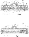
- Figs. 2 and 3 illustrate the advantageous design aspect that resides in having the elongated intermediate component 25 in the suction head 101.
- the elongated intermediate component 25 is suspended from a portion of the housing 30 at a position of the concavely curved areas 34, 35 of the surface 32 of the housing 30 facing the brushes 20.
- the elongated intermediate component 25 functions to close the space 24 between the two brushes 20, so that air entrance practically only takes place at the bottom side of the brushes 20.
- the brushes 20 fill the entire opening at the bottom side of the suction head 101.
- This arrangement of the brushes 20 is supported not only by the presence of the elongated intermediate component 25, but also by the presence of other constructional details such as spoilers and edges with cavities, and also side walls at the position of which the surface 32 of the housing 30 facing the brushes 20 comprises areas 36 covering the ends of the brushes 20.
- air mainly enters through the brush 20 at the position of the flexible microfiber elements 23 thereof and gaps between the encapsulation and the brushes 20.
- Fig. 3 it can be seen that in the shown embodiment of the suction head 101, approximately the upper 75% of the brushes 20 is encapsulated at only a small distance, such as a distance of about 1 mm. As explained earlier, this is beneficial because narrow gaps are realized in which air speeds can be relatively high, whereby the functionality of dirt transport in the suction head 101, eventually directed towards the coupling area 33, is supported.
- Surfaces of the elongated intermediate component 25 facing the brushes 20 are preferably smooth, as opposed to uneven surfaces, and the same is applicable to the surface 32 of the housing 30 facing the brushes 20 at the position of a housing part 37 located at more or less the same level as the elongated intermediate component 25, which is a level at or below the level of the rotation axes 21 of the brushes 20.
- the surface 32 of the housing 30 facing the brushes 20 comprises two adjacent concavely curved areas 34, 35, wherein one 34 of the concavely curved areas 34, 35 covers a portion of a front brush 20a, and wherein the other 35 of the concavely curved areas 34, 35 covers a portion of a rear brush 20b.
- the terms "front” and “rear” are to be understood so as to relate to the normal position of a user handling a vacuum cleaner 100 including the suction head 101, which is a position at the side of the rear brush 20b. During operation, the user moves the suction head 101 to and fro with the front brush 20a at the front and the rear brush 20b at the rear.
- the surface 32 of the housing 30 facing the brushes 20 is provided with a plurality of grooves 39 at the position of the two adjacent concavely curved areas 34, 35, as can best be seen in Figs. 8-11 .
- the grooves 39 are shaped such as to promote movement of dirt that adheres to the brushes 20 towards the outlet opening 31 in the surface 32 as the brushes 20 rotate. This advantageous effect relies on the following aspects, independently from each other or in interaction with each other:
- the housing parts 37, 38 which serve to cover the brushes 20 at close range, with the exception of the portion of the brushes 20 that is to be exposed to the surface 10 to be cleaned, functionally constitute one encapsulation but can be provided as separate parts joined together during the manufacturing process of the suction head 101 for practical reasons, particularly reasons of manufacturability.
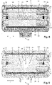
- Fig. 4 shows a view of a cross-section of the suction head 101 that is taken at a position on the suction head 101 that is a central position as seen in a longitudinal direction / being the direction which the rotation axes 21 of the brushes 20 extend.
- the brushes 20 are exposed to an tube-shaped element 27 of an airflow directing component 28, which leads up to the coupling area 33 and is intended to be coupled to the suction channel 51 mentioned earlier at the position of the coupling area 33, and also to fang-like parts 29 of the airflow directing component 28, as will be explained later.
- a part of the wall of the tube-shaped element 27 that is at a position above the outlet opening 31 is oriented non-perpendicular relative to an upward flow of liquid, dirt and air received from the area 24 between the brushes 20, as indicated by an arrow in Fig. 4 . In this way, it is achieved that the flow is smoothly bent in rearward direction, towards the coupling area 33, and that deposition of dirt on the wall of the tube-shaped element 27 is avoided.
- the outlet opening 31 is dimensioned to cover only a portion of a dimension of the brushes 20 in the longitudinal direction /, i.e. the length of the brushes 20.
- the outlet opening 31 has a stretched appearance in the longitudinal direction / for the purpose of receiving dirt along the entire length of the brushes 20.
- a drawback of such a conventional shape of the outlet opening 31 is that the air speed is lower and that internal surfaces will tend more to a perpendicular orientation relative to the airflow so that there is a higher risk of pollution of the internal surfaces.
- the size of the outlet opening 31 and the cross-section of the tube-shaped element 27 to which the outlet opening 31 provides access are large enough to realize acceptable resistance.
- the wall of the tube-shaped element 27 is preferably nowhere perpendicular (or near-perpendicular) to the direction of the flow of liquid, dirt and air so that deposition of dirt at one or more areas on the wall can be prevented.
- a height of the portion of the front brush 20a that is exposed to the tube-shaped element 27 through the outlet opening 31 is between 0.3 and 0.5 the brush diameter
- a length of the portion of the front brush 20a that is exposed to the tube-shaped element 27 through the outlet opening 31 is between 0.8 and 1.3 the brush diameter
- iii) in a horizontal direction perpendicular to the longitudinal direction /, a dimension Q of the portion of the two brushes 20 that is exposed to the tube-shaped element 27 through the outlet opening 31 is between 0.6 and 1.1.
- a cross-section of the tube-shaped element 27 taken in vertical direction between the brushes 20, i.e. at the interface of the concavely curved areas 34, 35 of the surface 32 of the housing 30 facing the brushes 20, as can be seen in Fig. 6 has an arc-shape and a substantially straight base, wherein the arc-shape may be circular, for example, or triangular with a rounded top, and v) an angle ⁇ between the horizontal direction and the root of the arc-shape is at least 60°, wherein a value of about 67.5° may be a preferred value for effective prevention of dirt deposition on internal surfaces.
- arc-shape of the cross-section of the tube-shaped element 27 connects fluently to the downstream portion of the tube-shaped element 27.
- Figs. 5 and 7 show cross-sections of the tube-shaped element 27 at other positions, and also illustrate the arc-shape. For the sake of clarity, it is noted that in both these figures, sections of bearing/driving structures for a brush 20 are shown.
- Figs. 8 and 9 provide an impression of the outline of the outlet opening 31, as seen from the bottom, i.e. from the side where the brushes 20 are arranged.
- Figs. 10 and 11 provide an impression of the intersection of the airflow directing component 28 with the housing 30, wherein it is noted that the fang-like parts 29 of the airflow directing component 28 extend all the way to the level of the rotation axes 21 of the brushes 20.
- the fang-like parts 29 extend on sides of the tube-shaped element 27 which are opposite sides in a direction perpendicular to a longitudinal direction of the tube-shaped element 27 and reach down to the level of the rotation axes 21 of the brushes 20 at the position of the interface of the concavely curved areas 34, 35 of the surface 32 of the housing 30 in which the outlet opening 31 is present.
- the conduit system 43 of the wetting arrangement 42 comprises two main conduits 44, 45 which are located in different halves of the suction head 101 as seen in the longitudinal direction l , and which are couplable to the liquid supply mechanism 41. Further, the conduit system 43 comprises two branch conduits 46, 47, 48, 49 per main conduit 44, 45, namely one branch conduit 46, 49 that is configured to let out liquid to a wheels 90, and another branch conduit 47, 48 that is configured to let out liquid to an area of the surface 10 to be cleaned.
- the branch conduits 47, 48 which are configured to let out liquid to the surface 10 to be cleaned are arranged to partially extend through the elongated intermediate component 25, and the liquid supplying positions where the liquid is let out to the surface 10 are at a bottom side of the elongated intermediate component 25, i.e. at a bottom surface portion 26 of the elongated intermediate component 25 that is configured to face the surface 10 to be cleaned.
- the wetting arrangement 42 illustrated here is just one of the many examples which are feasible in the context of the invention and which may have any desired wetting functionality, which may at least include one of directly wetting at least one of the brushes 20 and indirectly wetting at least one of the brushes 20.
- the suction head 101 comprises an elongated intermediate element 25 covering a portion of the brushes 20 from the bottom side of the suction head 101, as is the case in the shown embodiment of the suction head 101, it may be beneficial to use the elongated intermediate element 25 to accommodate at least a portion of one or more conduits of a conduit system 43 of the wetting arrangement 42, which does not alter the fact that the invention also covers other options.
- the bottom surface portion 26 of the elongated intermediate component 25 is at a relatively low level, which may be a level that is at least 2 mm and at most 6 mm above a level of the surface 10 to be cleaned when the suction head 101 is in an operational position on the surface 10.
- a relatively low level which may be a level that is at least 2 mm and at most 6 mm above a level of the surface 10 to be cleaned when the suction head 101 is in an operational position on the surface 10.
- a suction head 101 that is of the type that is configured to be applied in a vacuum cleaner 100 and to perform a cleaning action on a surface 10, and that comprises a housing 30 and two rotatable brushes 20 in a substantially parallel arrangement in the housing 30, a surface 32 of the housing 30 facing the brushes 20 comprises two adjacent concavely curved areas 34, 35, wherein each of the concavely curved areas 34, 35 covers a portion of a respective one 20a, 20b of the brushes 20.
- the surface 32 of the housing 30 facing the brushes 20 is provided with an outlet opening 31 that is in fluid communication with a coupling area 33 of the suction head 101, and the outlet opening 31 is at a position of an interface of the concavely curved areas 34, 35 and is dimensioned to cover only a portion of a length of the brushes 20.
Abstract
In a suction head (101) that is of the type that is configured to be applied in a vacuum cleaner and to perform a cleaning action on a surface (10), and that comprises a housing (30) and two rotatable brushes (20) in a substantially parallel arrangement in the housing (30), a surface (32) of the housing (30) facing the brushes (20) comprises two adjacent concavely curved areas (34, 35), wherein each of those areas (34, 35) covers a portion of a respective one (20a, 20b) of the brushes (20). Further, the surface (32) is provided with an outlet opening (31) that is in fluid communication with a coupling area (33) of the suction head (101), and the outlet opening (31) is at a position of an interface of the concavely curved areas (34, 35) and is dimensioned to cover only a portion of a length of the brushes (20).
Description
- The invention relates to a suction head configured to be applied in a vacuum cleaner and to perform a cleaning action on a surface, the suction head comprising: a housing that includes a coupling area configured to enable coupling of the housing to an air suction source of the vacuum cleaner, and two brushes in a substantially parallel arrangement in the housing, wherein each of the brushes is rotatable about a rotation axis and is configured to interact with the surface to be cleaned, and wherein each of the brushes is designed to be capable to pick up liquids from the surface.
- Further, the invention relates to a cordless vacuum cleaner comprising a suction head as mentioned.
- Vacuum cleaners are known for removing dirt from a surface to be cleaned. The term "dirt" as used in the present text is to be understood so as to cover any contamination as may be present on a surface and that can be removed under the influence of a vacuum cleaning action, probably combined with another cleaning action such as mopping. Practical examples in this respect include dust and small particles of any kind, and also wet types of contamination such as spilled drinks. A practical example of the surface to be cleaned is a floor, wherein the floor may be of any kind, such as a wooden floor, a carpet floor, a tile floor, etc.
- Generally, a vacuum cleaner has a vacuum cleaner head or suction head, which is the part of the vacuum cleaner where the actual process of picking up dirt from a surface to be cleaned is to take place and which is therefore to be put on or at least close to the surface. Further, a vacuum cleaner normally comprises a body portion including a dirt accumulating area, and an arrangement configured to act on the suction head so that a suction force is prevailing in the suction head during operation of the vacuum cleaner. The suction force serves to facilitate transport of dirt that is picked up from the surface during operation of the vacuum cleaner towards the dirt accumulating area, wherein the dirt is made to pass an outlet opening in a housing of the suction head. The suction force may also have a function in the actual process of picking up the dirt from the surface. On the other hand, the suction head may be equipped with at least one movable component for interacting with the surface in order to pick up the dirt, such as at least one rotatable brush that may serve as an agitator of the dirt and that may particularly be configured to help dislodge dirt from the surface and direct it towards the outlet opening.
-
WO 2011/083373 A1 discloses a cleaning device for removing particles from a surface, comprising spraying means for spraying droplets of a work fluid, a rotatable brush having flexible brush elements, an inlet for receiving dirtied air such as air laden with particles, and a cleansing unit. The cleansing unit is suitable for separating at least a portion of the droplets of work fluid from the air. During operation, the rotatable brush is wetted by the work fluid. The brush is of such a dimension and is rotated at such a rotational speed that the droplets of the work fluid are expelled as a mist of droplets from the flexible brush elements into a coalescing space of the device. The dirtied air received by the inlet is receivable by the coalescing space, to form coalesced particles of the droplets expelled from the brush elements and particles in the dirtied air, the coalesced particles being conveyable from the coalescing space to the cleansing unit. -
WO 2012/107876 A1 discloses a cleaning device comprising a head having an open side for facing surfaces to be cleaned, and at least one brush for contacting surfaces to be cleaned, which is rotatably arranged in the head. The at least one brush is provided with a plurality of brush hairs, wherein it is possible that these brush hairs are extremely soft and flexible. In such a case, a cleaning action of a surface is not performed by scrubbing the surface but by putting the brush hairs alternately in and out of contact with the surface during rotation of the brush. In particular, during one revolution of the brush, the brush hairs remove particles and/or liquid droplets from a soiled surface and fling away the particles and/or the droplets when they reach a position in which they are free from contact to the surface and in which they can be fully outstretched. In the head of the cleaning device, in which the brush is arranged, there are means for receiving the particles and/or the droplets, and for possibly transporting the particles and/or the droplets towards a space where they are collected. The cleaning device may be equipped with means for realizing a suction force at the head in order to direct the particles and/or the droplets in a desired direction once they are released from the brush hairs. Further, it is possible that the cleaning device is configured to supply a cleaning liquid to the rotating brush in order to promote the adherence of particles to the brush hairs and/or to realize an additional cleaning effect on a surface to be cleaned. -
WO 2017/071727 A1 discloses a vacuum cleaner head comprising a housing having a vacuum extraction zone and first and second rollers configured to locate against a surface to be cleaned, wherein each of the first and second rollers is configured to pick-up dirt from the surface and carry the dirt to the vacuum extraction zone in the housing of the vacuum cleaner head when being rotated and moved over the surface during operation. The vacuum extraction zone is defined between the outlet opening and the first and second rollers. When the vacuum cleaner head is used in a vacuum cleaner and the vacuum cleaner is operated, an airflow is generated through the vacuum extraction zone to the outlet opening. The vacuum cleaner head may further comprise a liquid dispenser to dispense a liquid onto the surface to be cleaned, and the vacuum cleaner head may further comprise a liquid dispenser to dispense a liquid onto at least one of the first and second rollers. Therefore, it is possible to dampen a surface to be cleaned to promote the removal of detritus from the surface. - In the field of suction heads used for wet vacuum cleaning, pollution of surfaces of those suction heads is a problem. The combination of liquid and debris is a good recipe for deposition of dirt on surfaces of a suction head, which surfaces include surfaces facing the brushes and will hereinafter be referred to as internal surfaces. This kind of pollution may be very hard to remove. Not completely dry depositions are a good climate for microorganisms to grow and produce smell. A user of the suction head will perceive both as non-hygienic. In some cases, the suction head needs to be subjected to a cleaning action after use or a number of uses.
- In general, it is an object of the invention to provide measures aimed at achieving good cleaning results of a vacuum cleaning action performed on a surface. Further, it is an object of the invention to provide measures aimed at preventing pollution of the suction head.
- In view of the foregoing, the invention provides a suction head configured to be applied in a vacuum cleaner and to perform a cleaning action on a surface, the suction head comprising: a housing that includes a coupling area configured to enable coupling of the housing to an air suction source of the vacuum cleaner, and two brushes in a substantially parallel arrangement in the housing, wherein each of the brushes is rotatable about a rotation axis and is configured to interact with the surface to be cleaned, and wherein each of the brushes is designed to be capable to pick up liquids from the surface, wherein a surface of the housing facing the brushes comprises two adjacent concavely curved areas, wherein each of the concavely curved areas covers a portion of a respective one of the brushes, wherein the surface of the housing facing the brushes is provided with an outlet opening that is in fluid communication with the coupling area, and wherein the outlet opening is at a position of an interface of the concavely curved areas and is dimensioned to cover only a portion of a dimension of the brushes in a longitudinal direction being the direction in which the rotation axes of the brushes extend.
- It follows from the foregoing definition of the suction head according to the invention that various features are applicable to the suction head. In the following, the background of these features is explained. According to an insight underlying the invention, in order to keep the internal surfaces of the suction head as clean as possible during use of the suction head, it is beneficial to keep air speed along the surfaces as high as possible. Three ways of increasing the air speed are acknowledged: i) creating high underpressure by creating resistance between ambient and air suction source, ii) forcing the airflow through narrow gaps, and iii) applying high suction power. The latter option is not interesting in the context of a battery-driven vacuum cleaner.
- In view of the foregoing, a first aspect of the approach of the invention is to create narrow gaps and to thereby increase air speed and underpressure. The invention may therefore involve encapsulation of the brushes in the areas of the brushes that are not intended to face the surface to be cleaned or to be exposed to the outlet opening in the surface of the housing facing the brushes. This aspect is at the basis of the feature according to which the surface of the housing facing the brushes comprises two adjacent concavely curved areas, wherein each of the concavely curved areas covers a portion of a respective one of the brushes.
- A second aspect of the approach of the invention is to have the outlet opening in the surface of the housing facing the brushes at an advantageous position in the suction head and to keep the size of the outlet opening limited. This aspect is at the basis of the feature according to which the outlet opening is at a position of an interface of the concavely curved areas and is dimensioned to cover only a portion of a length of the brushes, i.e. a dimension of the brushes in a longitudinal direction being the direction in which the rotation axes of the brushes extend. This is different from prior art solutions, in which the outlet opening is often stretched along (almost) the entire length of the brushes, i.e. the entire dimension of the brushes in the direction of the longitudinal axes of the brushes.
- Preferably, each of the concavely curved areas of the surface of the housing facing the brushes follows an operational outline of the portion of the respective one of the brushes at a distance that is at most 10 mm. It is even more preferred if the distance as mentioned in a range of 0 mm to 2 mm, so as to obtain air speeds along the surface of the housing that may actually involve a cleaning effect on said surface. The narrow gaps thus obtained also involve a cleaning effect on the basis of the fact that there is practically no room where dirt might build up.
- Further, it is beneficial if the narrow gaps are created along portions of the brushes which are as large as possible. In view thereof, it is advantageous if each of the concavely curved areas of the surface of the housing facing the brushes covers at least a portion of the respective one of the brushes being the top half of the brush. Preferably, at least 65% of a dimension of each of the brushes about the respective rotation axis is covered at a distance in a range of 0 mm to 2 mm. Further, it may be so that each of the concavely curved areas of the surface of the housing facing the brushes covers the respective one of the brushes along the entire length of the brush.
- In a practical embodiment of the suction head according to the invention, an operational shape of each of the brushes is generally the shape of a cylinder having a circular periphery, in other words, the operational shape of the brushes is generally the shape of a roller, which may be an elongated roller. In that case, in order to have the desired encapsulation of as much of the brushes as possible, it is advantageous if each of the concavely curved areas of the surface of the housing facing the brushes covers the respective one of the brushes at the position of a portion of the curved operational outline thereof, and if the surface of the housing facing the brushes also comprises areas covering the ends of the brushes.
- It is also practical if the suction head comprises an airflow directing component including a tube-shaped element that is in fluid communication with the outlet opening in the surface of the housing facing the brushes and that extends towards the coupling area. According to the invention, it may especially be so that the airflow directing component comprises fang-like parts being in fluid communication with the outlet opening in the surface of the housing and extending on sides of the tube-shaped element which are opposite sides in a direction perpendicular to a longitudinal direction of the tube-shaped element, at a position of the interface of the concavely curved areas of the surface of the housing facing the brushes. Among other things, having the fangs helps realizing a smooth introduction of the air in the tube-shaped element and to avoid deposition of dirt that might otherwise be expected.
- A measure aimed at preventing pollution of the wall of the tube-shaped element resides in a configuration in which a part of the wall of the tube-shaped element that is at a position above the outlet opening in the surface of the housing facing the brushes is oriented non-perpendicular relative to a flow direction being an upward direction from the surface to be cleaned through the outlet opening and in between the brushes. Avoiding sharp transitions and gradually bending the airflow to follow the orientation of the tube-shaped element are design-related aspects on the basis of which deposition of dirt is avoided. Further, in this respect, it is beneficial if the part of the wall of the tube-shaped element is generally arc-shaped as seen in a cross-section of the tube-shaped element at a position of the interface of the concavely curved areas of the surface of the housing facing the brushes.
- A further measure aimed at having narrow gaps around the brushes involves applying an elongated intermediate component that is located in an area between the brushes and that comprises two concavely curved portions configured to cover portions of the brushes in the suction head. It may particularly be so that the elongated intermediate component is suspended from a portion of the housing of the suction head at a position of the concavely curved areas of the surface of the housing facing the brushes. The elongated intermediate component may be an integral part of the housing or may be provided as a separate component that could be removably coupled to another component of the housing so as to allow repair or cleaning, for example.
- The invention covers further options of realizing cleaning effects on a surface to be cleaned and possibly also the internal surfaces of the suction head. For example, the suction head may comprise a wetting arrangement that is configured to enable a supply of liquid to at least one area of the surface to be cleaned and/or at least one area in the suction head. Assuming that the suction head comprises at least one wheel that is rotatably arranged on the suction head and that is configured to be in contact with the surface to be cleaned, it is possible that the wetting arrangement is further configured to enable a direct supply of liquid to the at least one wheel. The wetting arrangement can be provided more or less as an add-on to an existing design of a suction head, but it is also possible that the wetting arrangement is provided in a more integrated fashion. A practical example of the liquid is water or a mixture of water and a cleaning agent. It is practical if the wetting arrangement comprises a conduit system configured to transport liquid and to let out liquid one or more appropriate positions. In the case that the suction head comprises the above-mentioned elongated intermediate component, it may be so that the conduit system comprises at least one conduit extending through the elongated intermediate component.
- In order to promote movement of dirt that is picked up from the surface to be cleaned by the brushes towards the outlet opening in the surface of the housing facing the brushes, it is advantageous if the surface of the housing facing the brushes is provided with a plurality of grooves which are especially designed for this purpose by having the capability of directing dirt particles towards the outlet opening as the brushes rotate.
- In the context of the invention, the brushes may be of any type that is suitable to be used for picking up dirt from a surface to be cleaned, wherein the brushes may be chosen to be either identical or different. Each of the brushes may especially be designed to serve as an agitator, for example, agitating dirt particles as may be present on the surface. In a practical embodiment of the suction head according to the invention, at least one of the brushes comprises a core element and flexible microfiber elements arranged on the core element. In such a brush, a linear mass density lower than 150 g per 10 km may be applicable to the microfiber elements, or at least tip portions thereof, so that the microfiber elements really can be highly flexible. The linear mass density as mentioned may even be lower than 10 g per 10 km, 5 g per 10 km or 1 g per 10 km. Such microfiber elements can be placed on the core element in a dense arrangement so as to very effectively interact with a surface to be cleaned during operation of the suction head. Further, it may be practical if such microfiber elements are arranged on the core element in tufts.
- The invention further relates to a vacuum cleaner, particularly a cordless vacuum cleaner, comprising a suction head as defined and described in the foregoing, in which, among other things, the surface of the housing facing the brushes comprises two adjacent concavely curved areas, and in which the outlet opening is dimensioned to cover only a portion of the length of the brushes.
- The above-described and other aspects of the invention will be apparent from and elucidated with reference to the following detailed description of a practical embodiment of the suction head as defined and described in the foregoing.
- The invention will now be explained in greater detail with reference to the figures, in which equal or similar parts are indicated by the same reference signs, and in which:
-
Fig. 1 diagrammatically shows components of a wet vacuum cleaner according to an embodiment of the invention and a portion of a floor having a surface to be cleaned, -
Fig. 2 diagrammatically shows a bottom view of a suction head according to an embodiment of the invention, comprising a housing and two brushes, namely a front brush and a rear brush in a substantially parallel arrangement in the housing, -
Figs. 3 and4 diagrammatically show views of a cross-section of the suction head, taken at different longitudinal positions on the suction head, -
Fig. 5 diagrammatically shows a view of a longitudinal section of the section head, taken at a position of a centre line through the front brush, with the front brush removed, wherein a viewing direction is from front to rear, -
Fig. 6 diagrammatically shows a view of a longitudinal section of the section head, taken at a position between the two brushes, with the rear brush removed, wherein a viewing direction is from front to rear, -
Fig. 7 diagrammatically shows a view of a longitudinal section of the section head, taken at a position of a centre line through the rear brush, with the rear brush removed, wherein a viewing direction is from front to rear, -
Fig. 8 diagrammatically shows the bottom view of the suction head ofFig. 2 , with the brushes removed, -
Fig. 9 diagrammatically shows the bottom view of the suction head ofFig. 2 , with both the brushes and an elongated intermediate component removed, and -
Figs. 10 and 11 diagrammatically show top perspective views of components of the suction head, wherein a portion of the housing is shown in transparent fashion. -
Fig. 1 illustrates the design of awet vacuum cleaner 100 according to an embodiment of the invention. The particular vacuum cleaner represented inFig. 1 and described in the following is just one example of many types of vacuum cleaners which are feasible in the framework of the invention. In this respect, it is noted that the invention does not only relate to wet vacuum cleaners, but also to other types of vacuum cleaners such as dry vacuum cleaners only having a dry cleaning function and wet/dry vacuum cleaners having a dry cleaning function besides a wet cleaning function. - The
wet vacuum cleaner 100 is configured to be used for the purpose of subjecting asurface 10 such as a floor surface to a wet cleaning action.Fig. 1 shows thevacuum cleaner 100 in a normal, operational orientation relative to thesurface 10 to be cleaned. The use in the present text of a term having an orientation aspect is to be understood in relation to this normal, operational orientation of thevacuum cleaner 100 relative to thesurface 10 to be cleaned, wherein it is assumed that thesurface 10 is at a bottom position and thevacuum cleaner 100 is placed on thesurface 10. - At a side that is supposed to face the
surface 10 during operation of thevacuum cleaner 100, thevacuum cleaner 100 comprises asuction head 101 accommodating twobrushes 20 which are configured to interact with thesurface 10 during operation of thevacuum cleaner 100. In the following, it is assumed that each of thebrushes 20 is provided in the form of a roller that is rotatable about arotation axis 21 that is defined by a central longitudinal axis of the roller, and that each of thebrushes 20 comprises acore element 22 andflexible microfiber elements 23 arranged on thecore element 22, which does not alter the fact that other embodiments of thebrushes 20 are possible as well. In the case of abrush 20 comprisingflexible microfiber elements 23, the operational outline of thebrush 20 is the outline of thebrush 20 with theflexible microfiber elements 23 in fully outstretched condition. Thebrushes 20 may be identical, but this is not necessary in the context of the invention. As indicated inFig. 1 by means of curved arrows depicted at the position of thebrushes 20, thebrushes 20 are arranged so as to be rotatable in opposite directions with respect to each other about their respective rotation axes 21. Thesuction head 101 comprises ahousing 30 that is configured to partially cover thebrushes 20. Thehousing 30 can be made of a plastic material, for example. - Besides the
suction head 101, thevacuum cleaner 100 comprises abody portion 102 that is configured to be taken hold of by a user of thevacuum cleaner 100. Preferably, thesuction head 101 and thebody portion 102 are removably couplable to each other. Thebody portion 102 can be shaped in any appropriate way. The outline of thebody portion 102 as shown inFig. 1 is of a diagrammatical nature only. It is practical if thebody portion 102 comprises a handle so that a user can easily take hold of thebody portion 102 and move thevacuum cleaner 100 across thesurface 10 to be cleaned as desired. - For the purpose of driving the
brushes 20 during operation of thevacuum cleaner 100, thevacuum cleaner 100 is equipped with a suitable electric drive mechanism (not shown). For the purpose of powering the drive mechanism and probably also other components of thevacuum cleaner 100, thevacuum cleaner 100 may be connectable to the mains and/or may be equipped with a suitable battery arrangement. Preferably, thevacuum cleaner 100 is a cordless device comprising a rechargeable battery arrangement, in which case it may further be practical if thevacuum cleaner 100 is part of a set including a charging dock besides thevacuum cleaner 100. Such a set may also include a flushing tray that can be used for the purpose of cleaning thebrushes 20. In case thevacuum cleaner 100 is not equipped with a battery, a simple dock that is without charging ability may be provided for receiving and holding thevacuum cleaner 100 while thevacuum cleaner 100 is not being operated. - The
body portion 102 of thevacuum cleaner 100 includes aliquid reservoir 40 that serves for containing a liquid such as water or a mixture of water and a cleaning agent, and aliquid supply mechanism 41 that serves for supplying the liquid to a wettingarrangement 42 of thesuction head 101 during operation of thevacuum cleaner 100. Theliquid supply mechanism 41 may comprise any suitable type of pump arrangement, for example, or may be configured to enable displacement of the liquid as desired under the influence of gravity. In the shown example, the wettingarrangement 42 of thesuction head 101 is configured to enable both a direct supply of liquid to areas of thesurface 10 to be cleaned and a direct supply of liquid to twowheels 90 of thesuction head 101, as will be explained later in more detail. Further, in the shown example, thesuction head 101 comprises an elongatedintermediate component 25 that is located in anarea 24 between thebrushes 20 and that comprises two concavely curved portions configured to cover portions of thebrushes 20, and the wettingarrangement 42 comprises aconduit system 43 that is partially arranged in the elongatedintermediate component 25 and that is configured to transport the liquid and to let out the liquid to the areas of thesurface 10 and to the twowheels 90. InFig. 1 , theliquid reservoir 40, theliquid supply mechanism 41 and the wettingarrangement 42 of thesuction head 101 are indicated by means of dotted lines. It is practical if theliquid reservoir 40 is removably coupled to thebody portion 102 so that a user is enabled to separate theliquid reservoir 40 from thebody portion 102 when it is desired to take theliquid reservoir 40 to a place where theliquid reservoir 40 is to be filled with liquid. - The
body portion 102 of thevacuum cleaner 100 further includes adirt reservoir 50 that serves for receiving and accumulatingwet dirt 11 that is picked up from thesurface 10 by thebrushes 20 during operation of thevacuum cleaner 100. Thedirt reservoir 50 can be configured in numerous ways as conventionally available for accumulating wet dirt from theincoming dirt 11 that is picked up from thesurface 10 such as for instance a cyclonic arrangement or a tube-in-cup arrangement. Thebody portion 102 includes avacuum mechanism 60 configured to create underpressure that is functional to enable transport of thedirt 11 from the area where thebrushes 20 are located to thedirt reservoir 50 in thebody portion 102, through anoutlet opening 31 in asurface 32 of thehousing 30 facing thebrushes 20 and asuction channel 51 extending from the outlet opening 31 to thedirt reservoir 50. As can particularly be seen in the top perspective views of components of thesuction head 101 inFigs. 10 and 11 , thehousing 30 includes acoupling area 33 that is configured to enable coupling of thehousing 30 to the assembly of thesuction channel 51, thedirt reservoir 50 and thevacuum mechanism 60 in thebody portion 102 of thevacuum cleaner 100. Theoutlet opening 31 is in fluid communication with thiscoupling area 33. - Basic aspects of the way in which the
wet vacuum cleaner 100 is operated are as follows. During operation, thebrushes 20 are driven so as to rotate and theliquid supply mechanism 41 is activated so as to supply liquid to the wettingarrangement 42 of thesuction head 101 so that liquid may be let out to thesurface 10 to be cleaned and to the twowheels 90. Any stains as may be present on an area of thesurface 10 that is within reach of thebrushes 20 are detached under the influence of the liquid and agitation by thebrushes 20, and dirt particles and dust as may be present on the area of thesurface 10 are removed along with the liquid and conveyed to thedirt reservoir 50, passing through theoutlet opening 31 and thesuction channel 51 in the process. Thedirt 11 is picked up from thesurface 10 by tip portions of themicrofiber elements 23 of thebrushes 20 and is flung away from the tip portions as thebrushes 20 rotate, at a position where the tip portions move out of contact to thesurface 10. - As illustrated in
Fig. 1 , thevacuum cleaner 100 may be equipped with auser interface 70, whichuser interface 70 may include an on/offbutton 71, for example. Thevacuum cleaner 100 may further comprise a controllingsystem 80 including a microcontroller that is programmed to put thebrushes 20 in motion and to activate both theliquid supply mechanism 41 and thevacuum mechanism 60 in reaction to input received from the user through theuser interface 70 to that end. -
Figs. 2-11 serve to illustrate aspects of asuction head 101 according to an embodiment of the invention. In general, the design of thesuction head 101 is such that thebrushes 20 are encapsulated as much as possible without hampering the necessary interaction between thebrushes 20 and thesurface 10 to be cleaned, wherein it is possible to have effective transport of dirt towards theoutlet opening 31 and beyond under the influence of high underpressure and high air speeds. -
Figs. 2 and 3 illustrate the advantageous design aspect that resides in having the elongatedintermediate component 25 in thesuction head 101. Advantageously, as shown, the elongatedintermediate component 25 is suspended from a portion of thehousing 30 at a position of the concavelycurved areas surface 32 of thehousing 30 facing thebrushes 20. In any case, the elongatedintermediate component 25 functions to close thespace 24 between the twobrushes 20, so that air entrance practically only takes place at the bottom side of thebrushes 20. As can be seen inFig. 2 and also inFig. 3 , thebrushes 20 fill the entire opening at the bottom side of thesuction head 101. This arrangement of thebrushes 20 is supported not only by the presence of the elongatedintermediate component 25, but also by the presence of other constructional details such as spoilers and edges with cavities, and also side walls at the position of which thesurface 32 of thehousing 30 facing thebrushes 20 comprisesareas 36 covering the ends of thebrushes 20. Thus, it is achieved that during operation of thesuction head 101, air mainly enters through thebrush 20 at the position of theflexible microfiber elements 23 thereof and gaps between the encapsulation and thebrushes 20. - In
Fig. 3 , it can be seen that in the shown embodiment of thesuction head 101, approximately the upper 75% of thebrushes 20 is encapsulated at only a small distance, such as a distance of about 1 mm. As explained earlier, this is beneficial because narrow gaps are realized in which air speeds can be relatively high, whereby the functionality of dirt transport in thesuction head 101, eventually directed towards thecoupling area 33, is supported. Surfaces of the elongatedintermediate component 25 facing thebrushes 20 are preferably smooth, as opposed to uneven surfaces, and the same is applicable to thesurface 32 of thehousing 30 facing thebrushes 20 at the position of ahousing part 37 located at more or less the same level as the elongatedintermediate component 25, which is a level at or below the level of the rotation axes 21 of thebrushes 20. At anotherhousing part 38, particularly ahousing part 38 that is at a higher position, thesurface 32 of thehousing 30 facing thebrushes 20 comprises two adjacent concavelycurved areas curved areas curved areas rear brush 20b. The terms "front" and "rear" are to be understood so as to relate to the normal position of a user handling avacuum cleaner 100 including thesuction head 101, which is a position at the side of therear brush 20b. During operation, the user moves thesuction head 101 to and fro with the front brush 20a at the front and therear brush 20b at the rear. - Preferably, the
surface 32 of thehousing 30 facing thebrushes 20 is provided with a plurality ofgrooves 39 at the position of the two adjacent concavelycurved areas Figs. 8-11 . Thegrooves 39 are shaped such as to promote movement of dirt that adheres to thebrushes 20 towards the outlet opening 31 in thesurface 32 as thebrushes 20 rotate. This advantageous effect relies on the following aspects, independently from each other or in interaction with each other: - Liquids can be transported by means of the microfiber elements of the
brushes 20. Liquid drops are projected from the rotatingbrushes 20 to thesurface 32 of thehousing 30 facing thebrushes 20 and then guided by the groove geometry. The airflow created by the rotation of thebrushes 20 in the space between thebrushes 20 and thehousing 30 contributes to realizing movement of liquids in thegrooves 39. - Coarse particles are transported under the influence of forces induced by the rotation of the
brushes 20 and guided by the groove geometry. - Small particles are transported by means of the microfiber elements. Small particles can also be transported by interacting with other particles, by the airflow created by the rotation of the
brushes 20 in the space between thebrushes 20 and thehousing 30, and by interacting with liquids. - The
housing parts brushes 20 at close range, with the exception of the portion of thebrushes 20 that is to be exposed to thesurface 10 to be cleaned, functionally constitute one encapsulation but can be provided as separate parts joined together during the manufacturing process of thesuction head 101 for practical reasons, particularly reasons of manufacturability. -
Fig. 4 shows a view of a cross-section of thesuction head 101 that is taken at a position on thesuction head 101 that is a central position as seen in a longitudinal direction / being the direction which the rotation axes 21 of thebrushes 20 extend. At the position of theoutlet opening 31, thebrushes 20 are exposed to an tube-shapedelement 27 of anairflow directing component 28, which leads up to thecoupling area 33 and is intended to be coupled to thesuction channel 51 mentioned earlier at the position of thecoupling area 33, and also to fang-like parts 29 of theairflow directing component 28, as will be explained later. A part of the wall of the tube-shapedelement 27 that is at a position above theoutlet opening 31 is oriented non-perpendicular relative to an upward flow of liquid, dirt and air received from thearea 24 between thebrushes 20, as indicated by an arrow inFig. 4 . In this way, it is achieved that the flow is smoothly bent in rearward direction, towards thecoupling area 33, and that deposition of dirt on the wall of the tube-shapedelement 27 is avoided. - As explained in the foregoing, a large portion of the
brushes 20 is encapsulated so as to have high air speeds and to thereby promote dirt transport through thesuction head 101. Another advantageous effect of the high air speeds is that internal surfaces of thesuction head 101 can be kept clean. In thesuction head 101 according to the invention, theoutlet opening 31 is dimensioned to cover only a portion of a dimension of thebrushes 20 in the longitudinal direction /, i.e. the length of thebrushes 20. In this respect, it is noted that in many known suction heads, theoutlet opening 31 has a stretched appearance in the longitudinal direction / for the purpose of receiving dirt along the entire length of thebrushes 20. A drawback of such a conventional shape of theoutlet opening 31 is that the air speed is lower and that internal surfaces will tend more to a perpendicular orientation relative to the airflow so that there is a higher risk of pollution of the internal surfaces. By narrowing theoutlet opening 31 and the tube-shapedelement 27, not only the air speed is increased, but also the density of the liquid in the tube-shaped element is increased, which helps in flushing dirt from the tube-shapedelement 27. On the other hand, it is practical if the size of theoutlet opening 31 and the cross-section of the tube-shapedelement 27 to which theoutlet opening 31 provides access are large enough to realize acceptable resistance. Further, as explained, the wall of the tube-shapedelement 27 is preferably nowhere perpendicular (or near-perpendicular) to the direction of the flow of liquid, dirt and air so that deposition of dirt at one or more areas on the wall can be prevented. - Proper functioning of the suction head 101 in terms of effective dirt transport and prevention of dirt deposition on internal surfaces can be obtained if the following requirements are complied with, wherein these requirements are in no way to be understood so as to be essential to the invention: i) a height of the portion of the front brush 20a that is exposed to the tube-shaped element 27 through the outlet opening 31 is between 0.3 and 0.5 the brush diameter, ii) a length of the portion of the front brush 20a that is exposed to the tube-shaped element 27 through the outlet opening 31 is between 0.8 and 1.3 the brush diameter, iii) in a horizontal direction perpendicular to the longitudinal direction /, a dimension Q of the portion of the two brushes 20 that is exposed to the tube-shaped element 27 through the outlet opening 31 is between 0.6 and 1.1. times the distance P between the axes 21 of the brushes 20, iv) a cross-section of the tube-shaped element 27 taken in vertical direction between the brushes 20, i.e. at the interface of the concavely curved areas 34, 35 of the surface 32 of the housing 30 facing the brushes 20, as can be seen in
Fig. 6 , has an arc-shape and a substantially straight base, wherein the arc-shape may be circular, for example, or triangular with a rounded top, and v) an angle α between the horizontal direction and the root of the arc-shape is at least 60°, wherein a value of about 67.5° may be a preferred value for effective prevention of dirt deposition on internal surfaces. The arc-shape of the cross-section of the tube-shapedelement 27 connects fluently to the downstream portion of the tube-shapedelement 27.Figs. 5 and7 show cross-sections of the tube-shapedelement 27 at other positions, and also illustrate the arc-shape. For the sake of clarity, it is noted that in both these figures, sections of bearing/driving structures for abrush 20 are shown. -
Figs. 8 and 9 provide an impression of the outline of theoutlet opening 31, as seen from the bottom, i.e. from the side where thebrushes 20 are arranged.Figs. 10 and 11 provide an impression of the intersection of theairflow directing component 28 with thehousing 30, wherein it is noted that the fang-like parts 29 of theairflow directing component 28 extend all the way to the level of the rotation axes 21 of thebrushes 20. The fang-like parts 29 extend on sides of the tube-shapedelement 27 which are opposite sides in a direction perpendicular to a longitudinal direction of the tube-shapedelement 27 and reach down to the level of the rotation axes 21 of thebrushes 20 at the position of the interface of the concavelycurved areas surface 32 of thehousing 30 in which theoutlet opening 31 is present. - Details of the wetting
arrangement 42 of thesuction head 101 can best be seen inFig. 6 . Theconduit system 43 of the wettingarrangement 42 comprises twomain conduits suction head 101 as seen in the longitudinal direction l, and which are couplable to theliquid supply mechanism 41. Further, theconduit system 43 comprises twobranch conduits main conduit branch conduit wheels 90, and anotherbranch conduit surface 10 to be cleaned. Thebranch conduits surface 10 to be cleaned are arranged to partially extend through the elongatedintermediate component 25, and the liquid supplying positions where the liquid is let out to thesurface 10 are at a bottom side of the elongatedintermediate component 25, i.e. at abottom surface portion 26 of the elongatedintermediate component 25 that is configured to face thesurface 10 to be cleaned. - The wetting
arrangement 42 illustrated here is just one of the many examples which are feasible in the context of the invention and which may have any desired wetting functionality, which may at least include one of directly wetting at least one of thebrushes 20 and indirectly wetting at least one of thebrushes 20. When thesuction head 101 comprises an elongatedintermediate element 25 covering a portion of thebrushes 20 from the bottom side of thesuction head 101, as is the case in the shown embodiment of thesuction head 101, it may be beneficial to use the elongatedintermediate element 25 to accommodate at least a portion of one or more conduits of aconduit system 43 of the wettingarrangement 42, which does not alter the fact that the invention also covers other options. - It is advantageous if the
bottom surface portion 26 of the elongatedintermediate component 25 is at a relatively low level, which may be a level that is at least 2 mm and at most 6 mm above a level of thesurface 10 to be cleaned when thesuction head 101 is in an operational position on thesurface 10. Advantageous aspects of having such a small space between thesurface 10 to be cleaned and thebottom surface portion 26 of the elongatedintermediate component 25 include the following: - The liquid beneath the
bottom surface portion 26 bridges with thesurface 10 and cleans thebottom surface portion 26 by means of the surface tension, capturing small dirt particles that could adhere to thebottom surface portion 26. - The flow of clean liquid from the different positions at which the liquid is let out has a direct cleaning effect on the
bottom surface portion 26. - The movement of the
suction head 101 results in the area underneath thebottom surface portion 26 being in constant interaction with thebrushes 20. - It will be clear to a person skilled in the art that the scope of the invention is not limited to the examples discussed in the foregoing, but that several amendments and modifications thereof are possible without deviating from the scope of the invention as defined in the attached claims. It is intended that the invention be construed as including all such amendments and modifications insofar they come within the scope of the claims or the equivalents thereof. While the invention has been illustrated and described in detail in the figures and the description, such illustration and description are to be considered illustrative or exemplary only, and not restrictive. The invention is not limited to the disclosed embodiments. The drawings are schematic, wherein details which are not required for understanding the invention may have been omitted, and not necessarily to scale.
- Variations to the disclosed embodiments can be understood and effected by a person skilled in the art in practicing the claimed invention, from a study of the figures, the description and the attached claims. In the claims, the word "comprising" does not exclude other steps or elements, and the indefinite article "a" or "an" does not exclude a plurality. Any reference signs in the claims should not be construed as limiting the scope of the invention.
- Elements and aspects discussed for or in relation with a particular embodiment may be suitably combined with elements and aspects of other embodiments, unless explicitly stated otherwise. Thus, the mere fact that certain measures are recited in mutually different dependent claims does not indicate that a combination of these measures cannot be used to advantage.
- The terms "comprise" and "include" as used in this text will be understood by a person skilled in the art as covering the term "consist of". Hence, the term "comprise" or "include" may in respect of an embodiment mean "consist of", but may in another embodiment mean "contain/have/be equipped with at least the defined species and optionally one or more other species".
- Notable aspects of the invention are summarized as follows. In a
suction head 101 that is of the type that is configured to be applied in avacuum cleaner 100 and to perform a cleaning action on asurface 10, and that comprises ahousing 30 and tworotatable brushes 20 in a substantially parallel arrangement in thehousing 30, asurface 32 of thehousing 30 facing thebrushes 20 comprises two adjacent concavelycurved areas curved areas brushes 20. Further, thesurface 32 of thehousing 30 facing thebrushes 20 is provided with anoutlet opening 31 that is in fluid communication with acoupling area 33 of thesuction head 101, and theoutlet opening 31 is at a position of an interface of the concavelycurved areas brushes 20.
Claims (15)
- Suction head (101) configured to be applied in a vacuum cleaner (100) and to perform a cleaning action on a surface (10), the suction head (101) comprising:a housing (30) that includes a coupling area (33) configured to enable coupling of the housing (30) to an air suction source (60) of the vacuum cleaner (100), andtwo brushes (20) in a substantially parallel arrangement in the housing (30), wherein each of the brushes (20) is rotatable about a rotation axis (21) and is configured to interact with the surface (10) to be cleaned, and wherein each of the brushes (20) is designed to be capable to pick up liquids from the surface (10),wherein a surface (32) of the housing (30) facing the brushes (20) comprises two adjacent concavely curved areas (34, 35),wherein each of the concavely curved areas (34, 35) covers a portion of a respective one (20a, 20b) of the brushes (20),wherein the surface (32) of the housing (30) facing the brushes (20) is provided with an outlet opening (31) that is in fluid communication with the coupling area (33), andwherein the outlet opening (31) is at a position of an interface of the concavely curved areas (34, 35) and is dimensioned to cover only a portion of a dimension of the brushes (20) in a longitudinal direction (l) being the direction in which the rotation axes (21) of the brushes (20) extend.
- Suction head (101) according to claim 1, wherein each of the concavely curved areas (34, 35) of the surface (32) of the housing (30) facing the brushes (20) follows an operational outline of the portion of the respective one (20a, 20b) of the brushes (20) at a distance that is at most 10 mm.
- Suction head (101) according to claim 2, wherein each of the concavely curved areas (34, 35) of the surface (32) of the housing (30) facing the brushes (20) follows the operational outline of the portion of the respective one (20a, 20b) of the brushes (20) at a distance in a range of 0 mm to 2 mm.
- Suction head (101) according to any of claims 1-3, wherein each of the concavely curved areas (34, 35) of the surface (32) of the housing (30) facing the brushes (20) covers at least a portion of the respective one (20a, 20b) of the brushes (20) being the top half of the brush (20a, 20b).
- Suction head (101) according to any of claims 1-4, wherein at least 65% of a dimension of each of the brushes (20) about the respective rotation axis (21) is covered at a distance in a range of 0 mm to 2 mm.
- Suction head (101) according to any of claims 1-5, wherein each of the concavely curved areas (34, 35) of the surface (32) of the housing (30) facing the brushes (20) covers the respective one (20a, 20b) of the brushes (20) along the entire dimension of the brush (20) in the longitudinal direction (l).
- Suction head (101) according to any of claims 1-6, wherein an operational shape of each of the brushes (20) is generally the shape of a cylinder having a circular periphery, wherein each of the concavely curved areas (34, 35) of the surface (32) of the housing (30) facing the brushes (20) covers the respective one (20a, 20b) of the brushes (20) at the position of a portion of the curved operational outline thereof, and wherein the surface (32) of the housing (30) facing the brushes (20) also comprises areas (36) covering the ends of the brushes (20).
- Suction head (101) according to any of claims 1-7, comprising an airflow directing component (28) including a tube-shaped element (27) that is in fluid communication with the outlet opening (31) in the surface (32) of the housing (30) facing the brushes (20) and that extends towards the coupling area (33).
- Suction head (101) according to claim 8, wherein the airflow directing component (28) comprises fang-like parts (29) being in fluid communication with the outlet opening (31) in the surface (32) of the housing (30) and extending on sides of the tube-shaped element (27) which are opposite sides in a direction perpendicular to a longitudinal direction (l) of the tube-shaped element (27), at a position of the interface of the concavely curved areas (34, 35) of the surface (32) of the housing (30) facing the brushes (20).
- Suction head (101) according to claim 8 or 9, wherein a part of the wall of the tube-shaped element (27) that is at a position above the outlet opening (31) in the surface (32) of the housing (30) facing the brushes (20) is oriented non-perpendicular relative to a flow direction being an upward direction from the surface (10) to be cleaned through the outlet opening (31) and in between the brushes (20).
- Suction head (101) according to claim 10, wherein the part of the wall of the tube-shaped element (27) is generally arc-shaped as seen in a cross-section of the tube-shaped element (27) at a position of the interface of the concavely curved areas (34, 35) of the surface (32) of the housing (30) facing the brushes (20).
- Suction head (101) according to any of claims 1-11, comprising an elongated intermediate component (25) that is located in an area (24) between the brushes (20) and that comprises two concavely curved portions configured to cover portions of the brushes (20).
- Suction head (101) according to claim 12, wherein the elongated intermediate component (25) is suspended from a portion of the housing (30) of the suction head (101) at a position of the concavely curved areas (34, 35) of the surface (32) of the housing (30) facing the brushes (20).
- Suction head (101) according to any of claims 1-13, comprising a wetting arrangement (42) that is configured to enable a supply of liquid to at least one area of the surface (10) to be cleaned and/or at least one area in the suction head (101).
- Cordless vacuum cleaner (100), comprising a suction head (101) according to any of claims 1-14.
Priority Applications (8)
| Application Number | Priority Date | Filing Date | Title |
|---|---|---|---|
| EP21163038.9A EP4059405A1 (en) | 2021-03-17 | 2021-03-17 | Suction head for application in a vacuum cleaner |
| JP2023557023A JP2024508192A (en) | 2021-03-17 | 2022-03-09 | Suction head for application in vacuum cleaners |
| EP22711241.4A EP4262506A1 (en) | 2021-03-17 | 2022-03-09 | Suction head for application in a vacuum cleaner |
| KR1020237030220A KR102659063B1 (en) | 2021-03-17 | 2022-03-09 | Suction head for applications in vacuum cleaners |
| AU2022240881A AU2022240881A1 (en) | 2021-03-17 | 2022-03-09 | Suction head for application in a vacuum cleaner |
| PCT/EP2022/055993 WO2022194631A1 (en) | 2021-03-17 | 2022-03-09 | Suction head for application in a vacuum cleaner |
| CN202220548524.4U CN218870144U (en) | 2021-03-17 | 2022-03-14 | Suction head and cordless vacuum cleaner |
| CN202210247390.7A CN115104953A (en) | 2021-03-17 | 2022-03-14 | Suction head for vacuum cleaner |
Applications Claiming Priority (1)
| Application Number | Priority Date | Filing Date | Title |
|---|---|---|---|
| EP21163038.9A EP4059405A1 (en) | 2021-03-17 | 2021-03-17 | Suction head for application in a vacuum cleaner |
Publications (1)
| Publication Number | Publication Date |
|---|---|
| EP4059405A1 true EP4059405A1 (en) | 2022-09-21 |
Family
ID=74947091
Family Applications (2)
| Application Number | Title | Priority Date | Filing Date |
|---|---|---|---|
| EP21163038.9A Withdrawn EP4059405A1 (en) | 2021-03-17 | 2021-03-17 | Suction head for application in a vacuum cleaner |
| EP22711241.4A Pending EP4262506A1 (en) | 2021-03-17 | 2022-03-09 | Suction head for application in a vacuum cleaner |
Family Applications After (1)
| Application Number | Title | Priority Date | Filing Date |
|---|---|---|---|
| EP22711241.4A Pending EP4262506A1 (en) | 2021-03-17 | 2022-03-09 | Suction head for application in a vacuum cleaner |
Country Status (5)
| Country | Link |
|---|---|
| EP (2) | EP4059405A1 (en) |
| JP (1) | JP2024508192A (en) |
| CN (2) | CN115104953A (en) |
| AU (1) | AU2022240881A1 (en) |
| WO (1) | WO2022194631A1 (en) |
Citations (5)
| Publication number | Priority date | Publication date | Assignee | Title |
|---|---|---|---|---|
| JPS57189546U (en) * | 1981-05-29 | 1982-12-01 | ||
| WO2011083373A1 (en) | 2010-01-07 | 2011-07-14 | Koninklijke Philips Electronics N.V. | Cleaning device and vacuum cleaner |
| WO2012107876A1 (en) | 2011-02-08 | 2012-08-16 | Koninklijke Philips Electronics N.V. | Combination of a tray and a cleaning device for cleaning surfaces |
| US20140289999A1 (en) * | 2011-04-29 | 2014-10-02 | Irobot Corporation | Robotic Vacuum Cleaning System |
| WO2017071727A1 (en) | 2015-10-26 | 2017-05-04 | Koninklijke Philips N.V. | A vacuum cleaner head |
-
2021
- 2021-03-17 EP EP21163038.9A patent/EP4059405A1/en not_active Withdrawn
-
2022
- 2022-03-09 JP JP2023557023A patent/JP2024508192A/en active Pending
- 2022-03-09 EP EP22711241.4A patent/EP4262506A1/en active Pending
- 2022-03-09 AU AU2022240881A patent/AU2022240881A1/en active Pending
- 2022-03-09 WO PCT/EP2022/055993 patent/WO2022194631A1/en active Application Filing
- 2022-03-14 CN CN202210247390.7A patent/CN115104953A/en active Pending
- 2022-03-14 CN CN202220548524.4U patent/CN218870144U/en active Active
Patent Citations (5)
| Publication number | Priority date | Publication date | Assignee | Title |
|---|---|---|---|---|
| JPS57189546U (en) * | 1981-05-29 | 1982-12-01 | ||
| WO2011083373A1 (en) | 2010-01-07 | 2011-07-14 | Koninklijke Philips Electronics N.V. | Cleaning device and vacuum cleaner |
| WO2012107876A1 (en) | 2011-02-08 | 2012-08-16 | Koninklijke Philips Electronics N.V. | Combination of a tray and a cleaning device for cleaning surfaces |
| US20140289999A1 (en) * | 2011-04-29 | 2014-10-02 | Irobot Corporation | Robotic Vacuum Cleaning System |
| WO2017071727A1 (en) | 2015-10-26 | 2017-05-04 | Koninklijke Philips N.V. | A vacuum cleaner head |
Also Published As
| Publication number | Publication date |
|---|---|
| JP2024508192A (en) | 2024-02-22 |
| CN115104953A (en) | 2022-09-27 |
| EP4262506A1 (en) | 2023-10-25 |
| AU2022240881A1 (en) | 2023-11-02 |
| KR20230133397A (en) | 2023-09-19 |
| CN218870144U (en) | 2023-04-18 |
| WO2022194631A1 (en) | 2022-09-22 |
Similar Documents
| Publication | Publication Date | Title |
|---|---|---|
| US11457790B2 (en) | Floor cleaning machine | |
| CN212140337U (en) | Surface cleaning apparatus | |
| JP5960823B2 (en) | Cleaning device for cleaning the surface | |
| EP3897330B1 (en) | Sweeper/scrubber system capable of handling large debris | |
| CN100586357C (en) | Suction wet jet mop | |
| CN215937239U (en) | Vacuum cleaner and surface cleaning system | |
| JP2021122503A (en) | Floor cleaning device | |
| EP4059405A1 (en) | Suction head for application in a vacuum cleaner | |
| KR102659063B1 (en) | Suction head for applications in vacuum cleaners | |
| EP4059399A1 (en) | Supplying liquid to at least one area of a surface to be cleaned | |
| EP4059398A1 (en) | Supplying liquid to at least one wheel of a suction head | |
| EP4059397A1 (en) | Transport of dirt in a suction head for use in a vacuum cleaner | |
| JP7356656B1 (en) | Cleaning roller and vacuum cleaner | |
| JP5016374B2 (en) | Cleaning equipment for escalator steps |
Legal Events
| Date | Code | Title | Description |
|---|---|---|---|
| PUAI | Public reference made under article 153(3) epc to a published international application that has entered the european phase |
Free format text: ORIGINAL CODE: 0009012 |
|
| STAA | Information on the status of an ep patent application or granted ep patent |
Free format text: STATUS: THE APPLICATION HAS BEEN PUBLISHED |
|
| AK | Designated contracting states |
Kind code of ref document: A1 Designated state(s): AL AT BE BG CH CY CZ DE DK EE ES FI FR GB GR HR HU IE IS IT LI LT LU LV MC MK MT NL NO PL PT RO RS SE SI SK SM TR |
|
| STAA | Information on the status of an ep patent application or granted ep patent |
Free format text: STATUS: THE APPLICATION IS DEEMED TO BE WITHDRAWN |
|
| 18D | Application deemed to be withdrawn |
Effective date: 20230322 |