JP6044366B2 - 高圧ポンプの制御装置 - Google Patents
高圧ポンプの制御装置 Download PDFInfo
- Publication number
- JP6044366B2 JP6044366B2 JP2013015474A JP2013015474A JP6044366B2 JP 6044366 B2 JP6044366 B2 JP 6044366B2 JP 2013015474 A JP2013015474 A JP 2013015474A JP 2013015474 A JP2013015474 A JP 2013015474A JP 6044366 B2 JP6044366 B2 JP 6044366B2
- Authority
- JP
- Japan
- Prior art keywords
- solenoid
- energization
- valve
- valve opening
- period
- Prior art date
- Legal status (The legal status is an assumption and is not a legal conclusion. Google has not performed a legal analysis and makes no representation as to the accuracy of the status listed.)
- Active
Links
- 239000000446 fuel Substances 0.000 claims description 125
- 230000020169 heat generation Effects 0.000 claims description 27
- 230000007423 decrease Effects 0.000 claims description 24
- 230000008859 change Effects 0.000 claims description 17
- 230000009467 reduction Effects 0.000 description 32
- 238000013021 overheating Methods 0.000 description 22
- 238000010586 diagram Methods 0.000 description 16
- 238000002347 injection Methods 0.000 description 13
- 239000007924 injection Substances 0.000 description 13
- 238000000034 method Methods 0.000 description 10
- 230000000694 effects Effects 0.000 description 8
- 238000003825 pressing Methods 0.000 description 8
- 239000000498 cooling water Substances 0.000 description 5
- 238000012937 correction Methods 0.000 description 5
- 238000013461 design Methods 0.000 description 5
- 230000008569 process Effects 0.000 description 5
- 238000012360 testing method Methods 0.000 description 5
- 239000002828 fuel tank Substances 0.000 description 3
- 238000012545 processing Methods 0.000 description 3
- 230000000052 comparative effect Effects 0.000 description 2
- 230000003247 decreasing effect Effects 0.000 description 2
- 230000002265 prevention Effects 0.000 description 2
- 238000002485 combustion reaction Methods 0.000 description 1
- 239000002826 coolant Substances 0.000 description 1
- 230000003111 delayed effect Effects 0.000 description 1
- 238000005516 engineering process Methods 0.000 description 1
- 238000012986 modification Methods 0.000 description 1
- 230000004048 modification Effects 0.000 description 1
- 238000005086 pumping Methods 0.000 description 1
- 238000011160 research Methods 0.000 description 1
- 230000004044 response Effects 0.000 description 1
- 238000004904 shortening Methods 0.000 description 1
Images


Classifications
-
- F—MECHANICAL ENGINEERING; LIGHTING; HEATING; WEAPONS; BLASTING
- F02—COMBUSTION ENGINES; HOT-GAS OR COMBUSTION-PRODUCT ENGINE PLANTS
- F02D—CONTROLLING COMBUSTION ENGINES
- F02D41/00—Electrical control of supply of combustible mixture or its constituents
- F02D41/30—Controlling fuel injection
- F02D41/38—Controlling fuel injection of the high pressure type
- F02D41/3809—Common rail control systems
- F02D41/3836—Controlling the fuel pressure
- F02D41/3845—Controlling the fuel pressure by controlling the flow into the common rail, e.g. the amount of fuel pumped
-
- F—MECHANICAL ENGINEERING; LIGHTING; HEATING; WEAPONS; BLASTING
- F02—COMBUSTION ENGINES; HOT-GAS OR COMBUSTION-PRODUCT ENGINE PLANTS
- F02D—CONTROLLING COMBUSTION ENGINES
- F02D41/00—Electrical control of supply of combustible mixture or its constituents
- F02D41/20—Output circuits, e.g. for controlling currents in command coils
-
- F—MECHANICAL ENGINEERING; LIGHTING; HEATING; WEAPONS; BLASTING
- F02—COMBUSTION ENGINES; HOT-GAS OR COMBUSTION-PRODUCT ENGINE PLANTS
- F02M—SUPPLYING COMBUSTION ENGINES IN GENERAL WITH COMBUSTIBLE MIXTURES OR CONSTITUENTS THEREOF
- F02M59/00—Pumps specially adapted for fuel-injection and not provided for in groups F02M39/00 -F02M57/00, e.g. rotary cylinder-block type of pumps
- F02M59/20—Varying fuel delivery in quantity or timing
- F02M59/36—Varying fuel delivery in quantity or timing by variably-timed valves controlling fuel passages to pumping elements or overflow passages
- F02M59/366—Valves being actuated electrically
- F02M59/367—Pump inlet valves of the check valve type being open when actuated
-
- F—MECHANICAL ENGINEERING; LIGHTING; HEATING; WEAPONS; BLASTING
- F02—COMBUSTION ENGINES; HOT-GAS OR COMBUSTION-PRODUCT ENGINE PLANTS
- F02M—SUPPLYING COMBUSTION ENGINES IN GENERAL WITH COMBUSTIBLE MIXTURES OR CONSTITUENTS THEREOF
- F02M59/00—Pumps specially adapted for fuel-injection and not provided for in groups F02M39/00 -F02M57/00, e.g. rotary cylinder-block type of pumps
- F02M59/44—Details, components parts, or accessories not provided for in, or of interest apart from, the apparatus of groups F02M59/02 - F02M59/42; Pumps having transducers, e.g. to measure displacement of pump rack or piston
- F02M59/46—Valves
- F02M59/466—Electrically operated valves, e.g. using electromagnetic or piezoelectric operating means
-
- F—MECHANICAL ENGINEERING; LIGHTING; HEATING; WEAPONS; BLASTING
- F02—COMBUSTION ENGINES; HOT-GAS OR COMBUSTION-PRODUCT ENGINE PLANTS
- F02D—CONTROLLING COMBUSTION ENGINES
- F02D2200/00—Input parameters for engine control
- F02D2200/02—Input parameters for engine control the parameters being related to the engine
- F02D2200/06—Fuel or fuel supply system parameters
- F02D2200/0602—Fuel pressure
-
- F—MECHANICAL ENGINEERING; LIGHTING; HEATING; WEAPONS; BLASTING
- F02—COMBUSTION ENGINES; HOT-GAS OR COMBUSTION-PRODUCT ENGINE PLANTS
- F02D—CONTROLLING COMBUSTION ENGINES
- F02D2200/00—Input parameters for engine control
- F02D2200/02—Input parameters for engine control the parameters being related to the engine
- F02D2200/06—Fuel or fuel supply system parameters
- F02D2200/0606—Fuel temperature
Description
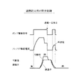
前記電磁アクチュエータ(27)のソレノイド(30)への通電を停止して該電磁アクチュエータ(27)の可動部(28)を閉側位置から開側位置に移動させると共に前記調量弁(23)を開弁させる開弁制御を実行する開弁制御手段(40)を備え、前記開弁制御手段は、前記開弁制御の際に、前記ソレノイドの発熱量を推定し、推定した前記発熱量が許容値以下の場合には、前記ポンプ室内の燃圧が低下して前記調量弁が開弁する後まで前記ソレノイドへの通電を継続して前記可動部を閉側位置に保持し、前記調量弁が開弁した後に前記ソレノイドへの通電を一旦停止することで、前記可動部を閉側位置に保持する期間を延長し、前記可動部が開側位置に到達する前に前記ソレノイドに一時的に再通電し、推定した前記発熱量が許容値を超える場合には、前記ポンプ室内の燃圧が低下して前記調量弁が開弁する前まで前記ソレノイドへの通電を継続して前記可動部を閉側位置に保持すると共に、前記調量弁が開弁する前に前記ソレノイドへの通電を一旦停止することで、推定した前記発熱量に応じて前記可動部を前記閉側位置に保持する期間を変更し、前記可動部が開側位置に到達する前に前記ソレノイドに一時的に再通電するようにしたものである。
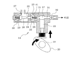
図1に示すように、燃料を貯溜する燃料タンク11内には、燃料を汲み上げる低圧ポンプ12が設置されている。この低圧ポンプ12は、バッテリ(図示せず)を電源とする電動モータ(図示せず)によって駆動される。この低圧ポンプ12から吐出される燃料は、燃料配管13を通して高圧ポンプ14に供給される。燃料配管13には、プレッシャレギュレータ15が接続され、このプレッシャレギュレータ15によって低圧ポンプ12の吐出圧力(高圧ポンプ14への燃料供給圧力)が所定圧力に調圧され、その圧力を越える燃料の余剰分が燃料戻し配管16により燃料タンク11内に戻されるようになっている。
L=P×V/(E×S) …(1)
尚、「通電延長期間」を「カム角又はクランク角」で設定する場合には、カム20の回転速度の影響を受けないため、カム20の回転速度に応じた変更を行う必要がない。
図17に示す開弁制御ルーチンは、ECU40の電源オン期間中(イグニッションスイッチのオン期間中)に所定周期で繰り返し実行され、特許請求の範囲でいう開弁制御手段としての役割を果たす。本ルーチンが起動されると、まず、ステップ101で、所定の音低減制御実行条件が成立しているか否かを、例えば、次の(1) 〜(5) の条件を全て満たすか否かによって判定する。
(2) 低速走行中又は停車中(車速≦所定値)であること
(3) アクセルオフ(アクセル開度=0)であること
(4) エンジン回転速度が安定状態(|目標回転速度−エンジン回転速度|≦所定値)であること
(5) 燃圧が安定状態(|目標燃圧−燃圧|≦所定値)であること
上記(1) 〜(5) の条件を全て満たせば、音低減制御実行条件が成立するが、上記(1) 〜(5) の条件のうちのいずれか1つでも満たさない条件があれば、音低減制御実行条件が不成立となる。
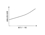
図18に示す条件変更ルーチンは、前記図17の開弁制御ルーチンのステップ105で実行されるサブルーチンである。本ルーチンが起動されると、まず、ステップ201で、ソレノイド30の発熱量の挙動を模擬した発熱量モデルを用いて、ソレノイド30の通電期間と、ソレノイド30の通電電流値(例えばピーク電流値や平均電流値等)と、高圧ポンプ14の温度に関する情報(例えば冷却水温や油温等)と、高圧ポンプ14の駆動速度に関する情報(例えばエンジン回転速度やポンプ回転速度等)に基づいてソレノイド30の推定発熱量を算出する。これにより、ソレノイド30の推定発熱量を精度良く算出することができる。ソレノイド30の発熱量モデルは、予め試験データや設計データ等に基づいて作成され、ECU40のROMに記憶されている。
Claims (4)
- 燃料の吸入口(21)と吐出口(31)を有するポンプ室(17)と、該ポンプ室(17)内で往復運動するプランジャ(18)と、前記吸入口(21)側を開閉する調量弁(23)と、該調量弁(23)を開閉移動させる電磁アクチュエータ(27)とを備えた高圧ポンプの制御装置において、
前記電磁アクチュエータ(27)のソレノイド(30)への通電を停止して該電磁アクチュエータ(27)の可動部(28)を閉側位置から開側位置に移動させると共に前記調量弁(23)を開弁させる開弁制御を実行する開弁制御手段(40)を備え、
前記開弁制御手段は、前記開弁制御の際に、前記ソレノイドの発熱量を推定し、
推定した前記発熱量が許容値以下の場合には、前記ポンプ室内の燃圧が低下して前記調量弁が開弁する後まで前記ソレノイドへの通電を継続して前記可動部を閉側位置に保持し、前記調量弁が開弁した後に前記ソレノイドへの通電を一旦停止することで、前記可動部を閉側位置に保持する期間を延長し、前記可動部が開側位置に到達する前に前記ソレノイドに一時的に再通電し、
推定した前記発熱量が許容値を超える場合には、前記ポンプ室内の燃圧が低下して前記調量弁が開弁する前まで前記ソレノイドへの通電を継続して前記可動部を閉側位置に保持すると共に、前記調量弁が開弁する前に前記ソレノイドへの通電を一旦停止することで、推定した前記発熱量に応じて前記可動部を前記閉側位置に保持する期間を変更し、前記可動部が開側位置に到達する前に前記ソレノイドに一時的に再通電する、高圧ポンプの制御装置。 - 前記開弁制御手段(40)は、推定した前記発熱量が許容値以下の場合、前記可動部(28)を前記閉側位置に保持する期間を燃料圧力に応じて変更することを特徴とする請求項1に記載の高圧ポンプの制御装置。
- 前記開弁制御手段(40)は、推定した前記発熱量が許容値を超える場合、前記ソレノイド(30)に一時的に再通電するタイミングを燃料圧力に応じて変更することを特徴とする請求項1に記載の高圧ポンプの制御装置。
- 前記開弁制御手段(40)は、前記ソレノイド(30)の推定発熱量を、前記ソレノイド(30)の通電期間、前記ソレノイド(30)の通電電流値、前記高圧ポンプ(14)の温度に関する情報、前記高圧ポンプ(14)の駆動速度に関する情報のうちの少なくとも一つに基づいて算出することを特徴とする請求項1乃至3のいずれかに記載の高圧ポンプの制御装置。
Priority Applications (3)
| Application Number | Priority Date | Filing Date | Title |
|---|---|---|---|
| JP2013015474A JP6044366B2 (ja) | 2013-01-30 | 2013-01-30 | 高圧ポンプの制御装置 |
| DE112014000612.2T DE112014000612B4 (de) | 2013-01-30 | 2014-01-28 | Steuervorrichtung für eine Hochdruckpumpe |
| PCT/JP2014/000429 WO2014119289A1 (ja) | 2013-01-30 | 2014-01-28 | 高圧ポンプの制御装置 |
Applications Claiming Priority (1)
| Application Number | Priority Date | Filing Date | Title |
|---|---|---|---|
| JP2013015474A JP6044366B2 (ja) | 2013-01-30 | 2013-01-30 | 高圧ポンプの制御装置 |
Publications (2)
| Publication Number | Publication Date |
|---|---|
| JP2014145339A JP2014145339A (ja) | 2014-08-14 |
| JP6044366B2 true JP6044366B2 (ja) | 2016-12-14 |
Family
ID=51262007
Family Applications (1)
| Application Number | Title | Priority Date | Filing Date |
|---|---|---|---|
| JP2013015474A Active JP6044366B2 (ja) | 2013-01-30 | 2013-01-30 | 高圧ポンプの制御装置 |
Country Status (3)
| Country | Link |
|---|---|
| JP (1) | JP6044366B2 (ja) |
| DE (1) | DE112014000612B4 (ja) |
| WO (1) | WO2014119289A1 (ja) |
Families Citing this family (5)
| Publication number | Priority date | Publication date | Assignee | Title |
|---|---|---|---|---|
| JP6265091B2 (ja) * | 2014-09-19 | 2018-01-24 | 株式会社デンソー | 高圧ポンプの制御装置 |
| US10557445B2 (en) | 2015-01-21 | 2020-02-11 | Hitachi Automotive Systems, Ltd | High-pressure fuel supply device for internal combustion engine |
| JP6464972B2 (ja) | 2015-09-24 | 2019-02-06 | 株式会社デンソー | 高圧ポンプ制御装置 |
| JP6710045B2 (ja) * | 2015-12-25 | 2020-06-17 | 日立オートモティブシステムズ株式会社 | 高圧燃料供給ポンプの制御方法およびそれを用いた高圧燃料供給ポンプ |
| DE102016216343A1 (de) * | 2016-08-30 | 2018-03-01 | Robert Bosch Gmbh | Verfahren zur Ansteuerung eines elektromagnetisch ansteuerbaren Einlassventils |
Family Cites Families (8)
| Publication number | Priority date | Publication date | Assignee | Title |
|---|---|---|---|---|
| JPH04153542A (ja) * | 1990-10-12 | 1992-05-27 | Nippondenso Co Ltd | 電磁弁駆動装置 |
| DE10148218B4 (de) * | 2001-09-28 | 2005-08-25 | Robert Bosch Gmbh | Verfahren zum Betreiben einer Brennkraftmaschine, Computerprogramm, Steuer- und/oder Regelgerät, sowie Kraftstoffsystem für eine Brennkraftmaschine |
| JP4327183B2 (ja) * | 2006-07-31 | 2009-09-09 | 株式会社日立製作所 | 内燃機関の高圧燃料ポンプ制御装置 |
| JP4338742B2 (ja) * | 2007-03-09 | 2009-10-07 | 三菱電機株式会社 | 内燃機関の高圧燃料ポンプ制御装置 |
| DE102008054512B4 (de) * | 2008-12-11 | 2021-08-05 | Robert Bosch Gmbh | Verfahren zum Betreiben eines Kraftstoffeinspritzsystems einer Brennkraftmaschine |
| US8677977B2 (en) * | 2010-04-30 | 2014-03-25 | Denso International America, Inc. | Direct injection pump control strategy for noise reduction |
| JP5183685B2 (ja) * | 2010-07-12 | 2013-04-17 | 日立オートモティブシステムズ株式会社 | 内燃機関の高圧燃料ポンプ制御装置 |
| JP5639970B2 (ja) * | 2011-08-03 | 2014-12-10 | 日立オートモティブシステムズ株式会社 | 電磁弁の制御方法、高圧燃料供給ポンプの電磁吸入弁の制御方法および電磁吸入弁の電磁駆動機構の制御装置 |
-
2013
- 2013-01-30 JP JP2013015474A patent/JP6044366B2/ja active Active
-
2014
- 2014-01-28 DE DE112014000612.2T patent/DE112014000612B4/de active Active
- 2014-01-28 WO PCT/JP2014/000429 patent/WO2014119289A1/ja active Application Filing
Also Published As
| Publication number | Publication date |
|---|---|
| WO2014119289A1 (ja) | 2014-08-07 |
| DE112014000612T5 (de) | 2015-10-15 |
| DE112014000612B4 (de) | 2020-12-24 |
| JP2014145339A (ja) | 2014-08-14 |
Similar Documents
| Publication | Publication Date | Title |
|---|---|---|
| JP5267446B2 (ja) | 内燃機関の燃料供給装置 | |
| JP6221828B2 (ja) | 高圧ポンプの制御装置 | |
| JP4327183B2 (ja) | 内燃機関の高圧燃料ポンプ制御装置 | |
| US9341181B2 (en) | Control device of high pressure pump | |
| JP6079487B2 (ja) | 高圧ポンプの制御装置 | |
| JP6044366B2 (ja) | 高圧ポンプの制御装置 | |
| US10655613B2 (en) | High-pressure pump control unit | |
| JP6265091B2 (ja) | 高圧ポンプの制御装置 | |
| US10161342B2 (en) | Control device for high-pressure pump | |
| JP2015014221A (ja) | 高圧ポンプの制御装置 | |
| JP5692131B2 (ja) | 高圧ポンプの制御装置 | |
| JP5991268B2 (ja) | 内燃機関の燃料供給装置 | |
| JP6222338B2 (ja) | 高圧ポンプの制御装置 | |
| JP5497556B2 (ja) | エンジンの制御装置 | |
| JP5812517B2 (ja) | 高圧ポンプの制御装置 | |
| WO2016170744A1 (ja) | 高圧ポンプの制御装置 | |
| US11519372B2 (en) | Control device for high-pressure pump and method for controlling the same | |
| JP5083169B2 (ja) | 燃料供給システム | |
| JP6341176B2 (ja) | 高圧ポンプの制御装置 | |
| JP2012225209A (ja) | 内燃機関の燃料供給装置 | |
| JP2015161297A (ja) | 燃料供給装置 | |
| JP6201711B2 (ja) | 内燃機関の燃料供給装置 | |
| JP2011226303A (ja) | 内燃機関の高圧ポンプ制御装置 | |
| JP2020204268A (ja) | 燃料噴射制御装置及び燃料噴射制御方法 | |
| JP2013142347A (ja) | インジェクタ駆動制御装置 |
Legal Events
| Date | Code | Title | Description |
|---|---|---|---|
| A621 | Written request for application examination |
Free format text: JAPANESE INTERMEDIATE CODE: A621 Effective date: 20151105 |
|
| RD04 | Notification of resignation of power of attorney |
Free format text: JAPANESE INTERMEDIATE CODE: A7424 Effective date: 20160307 |
|
| RD03 | Notification of appointment of power of attorney |
Free format text: JAPANESE INTERMEDIATE CODE: A7423 Effective date: 20160309 |
|
| A131 | Notification of reasons for refusal |
Free format text: JAPANESE INTERMEDIATE CODE: A131 Effective date: 20160426 |
|
| A521 | Request for written amendment filed |
Free format text: JAPANESE INTERMEDIATE CODE: A523 Effective date: 20160615 |
|
| A131 | Notification of reasons for refusal |
Free format text: JAPANESE INTERMEDIATE CODE: A131 Effective date: 20160719 |
|
| A521 | Request for written amendment filed |
Free format text: JAPANESE INTERMEDIATE CODE: A523 Effective date: 20160912 |
|
| TRDD | Decision of grant or rejection written | ||
| A01 | Written decision to grant a patent or to grant a registration (utility model) |
Free format text: JAPANESE INTERMEDIATE CODE: A01 Effective date: 20161018 |
|
| A61 | First payment of annual fees (during grant procedure) |
Free format text: JAPANESE INTERMEDIATE CODE: A61 Effective date: 20161031 |
|
| R151 | Written notification of patent or utility model registration |
Ref document number: 6044366 Country of ref document: JP Free format text: JAPANESE INTERMEDIATE CODE: R151 |
|
| R250 | Receipt of annual fees |
Free format text: JAPANESE INTERMEDIATE CODE: R250 |
|
| R250 | Receipt of annual fees |
Free format text: JAPANESE INTERMEDIATE CODE: R250 |
|
| R250 | Receipt of annual fees |
Free format text: JAPANESE INTERMEDIATE CODE: R250 |
|
| R250 | Receipt of annual fees |
Free format text: JAPANESE INTERMEDIATE CODE: R250 |