JP6001530B2 - Fuel assembly - Google Patents
Fuel assembly Download PDFInfo
- Publication number
- JP6001530B2 JP6001530B2 JP2013510271A JP2013510271A JP6001530B2 JP 6001530 B2 JP6001530 B2 JP 6001530B2 JP 2013510271 A JP2013510271 A JP 2013510271A JP 2013510271 A JP2013510271 A JP 2013510271A JP 6001530 B2 JP6001530 B2 JP 6001530B2
- Authority
- JP
- Japan
- Prior art keywords
- fuel
- elements
- assembly according
- fuel assembly
- kernel
- Prior art date
- Legal status (The legal status is an assumption and is not a legal conclusion. Google has not performed a legal analysis and makes no representation as to the accuracy of the status listed.)
- Active
Links
- 239000000446 fuel Substances 0.000 title claims description 1211
- 239000000463 material Substances 0.000 claims description 262
- 229910052751 metal Inorganic materials 0.000 claims description 145
- 239000002184 metal Substances 0.000 claims description 145
- 239000002826 coolant Substances 0.000 claims description 49
- 238000004519 manufacturing process Methods 0.000 claims description 37
- WZECUPJJEIXUKY-UHFFFAOYSA-N [O-2].[O-2].[O-2].[U+6] Chemical compound [O-2].[O-2].[O-2].[U+6] WZECUPJJEIXUKY-UHFFFAOYSA-N 0.000 claims description 33
- 229910000439 uranium oxide Inorganic materials 0.000 claims description 33
- 239000000956 alloy Substances 0.000 claims description 31
- XLYOFNOQVPJJNP-ZSJDYOACSA-N Heavy water Chemical compound [2H]O[2H] XLYOFNOQVPJJNP-ZSJDYOACSA-N 0.000 claims description 30
- 229910045601 alloy Inorganic materials 0.000 claims description 30
- 229910052770 Uranium Inorganic materials 0.000 claims description 26
- JFALSRSLKYAFGM-UHFFFAOYSA-N uranium(0) Chemical compound [U] JFALSRSLKYAFGM-UHFFFAOYSA-N 0.000 claims description 26
- 239000011358 absorbing material Substances 0.000 claims description 25
- 238000000034 method Methods 0.000 claims description 25
- QCWXUUIWCKQGHC-UHFFFAOYSA-N Zirconium Chemical compound [Zr] QCWXUUIWCKQGHC-UHFFFAOYSA-N 0.000 claims description 22
- 239000003870 refractory metal Substances 0.000 claims description 22
- 229910052726 zirconium Inorganic materials 0.000 claims description 22
- 229910052778 Plutonium Inorganic materials 0.000 claims description 21
- 239000011159 matrix material Substances 0.000 claims description 21
- OYEHPCDNVJXUIW-UHFFFAOYSA-N plutonium atom Chemical compound [Pu] OYEHPCDNVJXUIW-UHFFFAOYSA-N 0.000 claims description 21
- 238000013461 design Methods 0.000 claims description 19
- JFALSRSLKYAFGM-OIOBTWANSA-N uranium-235 Chemical compound [235U] JFALSRSLKYAFGM-OIOBTWANSA-N 0.000 claims description 18
- ZSLUVFAKFWKJRC-IGMARMGPSA-N 232Th Chemical compound [232Th] ZSLUVFAKFWKJRC-IGMARMGPSA-N 0.000 claims description 16
- 229910052776 Thorium Inorganic materials 0.000 claims description 16
- 239000012255 powdered metal Substances 0.000 claims description 15
- 238000005245 sintering Methods 0.000 claims description 15
- 238000005192 partition Methods 0.000 claims description 14
- 239000000919 ceramic Substances 0.000 claims description 13
- 239000011248 coating agent Substances 0.000 claims description 12
- 238000000576 coating method Methods 0.000 claims description 12
- 230000004323 axial length Effects 0.000 claims description 7
- 229910052782 aluminium Inorganic materials 0.000 claims description 5
- XAGFODPZIPBFFR-UHFFFAOYSA-N aluminium Chemical compound [Al] XAGFODPZIPBFFR-UHFFFAOYSA-N 0.000 claims description 5
- 238000002844 melting Methods 0.000 claims description 4
- 230000008018 melting Effects 0.000 claims description 4
- 230000000712 assembly Effects 0.000 description 25
- 238000000429 assembly Methods 0.000 description 25
- 238000005253 cladding Methods 0.000 description 24
- 125000006850 spacer group Chemical group 0.000 description 21
- 239000000843 powder Substances 0.000 description 12
- 239000006096 absorbing agent Substances 0.000 description 11
- 230000004992 fission Effects 0.000 description 11
- XLYOFNOQVPJJNP-UHFFFAOYSA-N water Substances O XLYOFNOQVPJJNP-UHFFFAOYSA-N 0.000 description 8
- 230000007246 mechanism Effects 0.000 description 7
- 238000012546 transfer Methods 0.000 description 7
- 238000001125 extrusion Methods 0.000 description 6
- 230000006872 improvement Effects 0.000 description 6
- 230000007547 defect Effects 0.000 description 5
- 238000002156 mixing Methods 0.000 description 5
- 230000007704 transition Effects 0.000 description 5
- 229910001093 Zr alloy Inorganic materials 0.000 description 4
- 238000009835 boiling Methods 0.000 description 4
- 230000000694 effects Effects 0.000 description 4
- 150000002739 metals Chemical class 0.000 description 4
- 239000011812 mixed powder Substances 0.000 description 4
- 239000008188 pellet Substances 0.000 description 4
- 230000008569 process Effects 0.000 description 4
- 230000009467 reduction Effects 0.000 description 4
- 241000006966 Areva Species 0.000 description 3
- ZOXJGFHDIHLPTG-UHFFFAOYSA-N Boron Chemical compound [B] ZOXJGFHDIHLPTG-UHFFFAOYSA-N 0.000 description 3
- ZOKXTWBITQBERF-UHFFFAOYSA-N Molybdenum Chemical compound [Mo] ZOKXTWBITQBERF-UHFFFAOYSA-N 0.000 description 3
- 230000008901 benefit Effects 0.000 description 3
- 229910052796 boron Inorganic materials 0.000 description 3
- 238000005266 casting Methods 0.000 description 3
- 230000008859 change Effects 0.000 description 3
- 238000006243 chemical reaction Methods 0.000 description 3
- 239000000203 mixture Substances 0.000 description 3
- 238000012986 modification Methods 0.000 description 3
- 230000004048 modification Effects 0.000 description 3
- 229910052750 molybdenum Inorganic materials 0.000 description 3
- 239000011733 molybdenum Substances 0.000 description 3
- 238000013021 overheating Methods 0.000 description 3
- 238000004663 powder metallurgy Methods 0.000 description 3
- NBWXXYPQEPQUSB-UHFFFAOYSA-N uranium zirconium Chemical compound [Zr].[Zr].[U] NBWXXYPQEPQUSB-UHFFFAOYSA-N 0.000 description 3
- RTAQQCXQSZGOHL-UHFFFAOYSA-N Titanium Chemical compound [Ti] RTAQQCXQSZGOHL-UHFFFAOYSA-N 0.000 description 2
- -1 U-233) Chemical compound 0.000 description 2
- 229910002056 binary alloy Inorganic materials 0.000 description 2
- INAHAJYZKVIDIZ-UHFFFAOYSA-N boron carbide Chemical compound B12B3B4C32B41 INAHAJYZKVIDIZ-UHFFFAOYSA-N 0.000 description 2
- 230000008878 coupling Effects 0.000 description 2
- 238000010168 coupling process Methods 0.000 description 2
- 238000005859 coupling reaction Methods 0.000 description 2
- 238000009826 distribution Methods 0.000 description 2
- 239000012530 fluid Substances 0.000 description 2
- 230000004907 flux Effects 0.000 description 2
- 229910001092 metal group alloy Inorganic materials 0.000 description 2
- 239000003758 nuclear fuel Substances 0.000 description 2
- 230000002093 peripheral effect Effects 0.000 description 2
- 239000007787 solid Substances 0.000 description 2
- 238000003466 welding Methods 0.000 description 2
- 241000239290 Araneae Species 0.000 description 1
- 229910052580 B4C Inorganic materials 0.000 description 1
- VYZAMTAEIAYCRO-UHFFFAOYSA-N Chromium Chemical compound [Cr] VYZAMTAEIAYCRO-UHFFFAOYSA-N 0.000 description 1
- 229910052692 Dysprosium Inorganic materials 0.000 description 1
- 229910052691 Erbium Inorganic materials 0.000 description 1
- 229910052688 Gadolinium Inorganic materials 0.000 description 1
- DGAQECJNVWCQMB-PUAWFVPOSA-M Ilexoside XXIX Chemical compound C[C@@H]1CC[C@@]2(CC[C@@]3(C(=CC[C@H]4[C@]3(CC[C@@H]5[C@@]4(CC[C@@H](C5(C)C)OS(=O)(=O)[O-])C)C)[C@@H]2[C@]1(C)O)C)C(=O)O[C@H]6[C@@H]([C@H]([C@@H]([C@H](O6)CO)O)O)O.[Na+] DGAQECJNVWCQMB-PUAWFVPOSA-M 0.000 description 1
- 229910001182 Mo alloy Inorganic materials 0.000 description 1
- KJTLSVCANCCWHF-UHFFFAOYSA-N Ruthenium Chemical compound [Ru] KJTLSVCANCCWHF-UHFFFAOYSA-N 0.000 description 1
- 206010040844 Skin exfoliation Diseases 0.000 description 1
- 241000270666 Testudines Species 0.000 description 1
- 241000221484 Tilletiaceae Species 0.000 description 1
- 229910000711 U alloy Inorganic materials 0.000 description 1
- BCEYEWXLSNZEFA-UHFFFAOYSA-N [Ag].[Cd].[In] Chemical compound [Ag].[Cd].[In] BCEYEWXLSNZEFA-UHFFFAOYSA-N 0.000 description 1
- LZJLRRQFSBMOGR-UHFFFAOYSA-N [Zr].[Pu] Chemical compound [Zr].[Pu] LZJLRRQFSBMOGR-UHFFFAOYSA-N 0.000 description 1
- 229910002065 alloy metal Inorganic materials 0.000 description 1
- PONLSTWIGVAHBQ-UHFFFAOYSA-N azane plutonium Chemical compound N.[Pu] PONLSTWIGVAHBQ-UHFFFAOYSA-N 0.000 description 1
- 230000004888 barrier function Effects 0.000 description 1
- SHZGCJCMOBCMKK-KGJVWPDLSA-N beta-L-fucose Chemical compound C[C@@H]1O[C@H](O)[C@@H](O)[C@H](O)[C@@H]1O SHZGCJCMOBCMKK-KGJVWPDLSA-N 0.000 description 1
- 230000015572 biosynthetic process Effects 0.000 description 1
- 229910052793 cadmium Inorganic materials 0.000 description 1
- 238000012993 chemical processing Methods 0.000 description 1
- 229910052804 chromium Inorganic materials 0.000 description 1
- 239000011651 chromium Substances 0.000 description 1
- 230000003247 decreasing effect Effects 0.000 description 1
- 238000012217 deletion Methods 0.000 description 1
- 230000037430 deletion Effects 0.000 description 1
- 238000010612 desalination reaction Methods 0.000 description 1
- 238000010586 diagram Methods 0.000 description 1
- 239000012153 distilled water Substances 0.000 description 1
- KBQHZAAAGSGFKK-UHFFFAOYSA-N dysprosium atom Chemical compound [Dy] KBQHZAAAGSGFKK-UHFFFAOYSA-N 0.000 description 1
- 230000005611 electricity Effects 0.000 description 1
- 230000008030 elimination Effects 0.000 description 1
- 238000003379 elimination reaction Methods 0.000 description 1
- UYAHIZSMUZPPFV-UHFFFAOYSA-N erbium Chemical compound [Er] UYAHIZSMUZPPFV-UHFFFAOYSA-N 0.000 description 1
- 238000007667 floating Methods 0.000 description 1
- UIWYJDYFSGRHKR-UHFFFAOYSA-N gadolinium atom Chemical compound [Gd] UIWYJDYFSGRHKR-UHFFFAOYSA-N 0.000 description 1
- 229910001938 gadolinium oxide Inorganic materials 0.000 description 1
- 229940075613 gadolinium oxide Drugs 0.000 description 1
- CMIHHWBVHJVIGI-UHFFFAOYSA-N gadolinium(iii) oxide Chemical compound [O-2].[O-2].[O-2].[Gd+3].[Gd+3] CMIHHWBVHJVIGI-UHFFFAOYSA-N 0.000 description 1
- 229910052735 hafnium Inorganic materials 0.000 description 1
- VBJZVLUMGGDVMO-UHFFFAOYSA-N hafnium atom Chemical compound [Hf] VBJZVLUMGGDVMO-UHFFFAOYSA-N 0.000 description 1
- 238000010438 heat treatment Methods 0.000 description 1
- 229910052738 indium Inorganic materials 0.000 description 1
- 238000003780 insertion Methods 0.000 description 1
- 230000037431 insertion Effects 0.000 description 1
- 230000014759 maintenance of location Effects 0.000 description 1
- 239000007769 metal material Substances 0.000 description 1
- 238000005272 metallurgy Methods 0.000 description 1
- 239000003607 modifier Substances 0.000 description 1
- 239000011823 monolithic refractory Substances 0.000 description 1
- 229910052758 niobium Inorganic materials 0.000 description 1
- 239000010955 niobium Substances 0.000 description 1
- GUCVJGMIXFAOAE-UHFFFAOYSA-N niobium atom Chemical compound [Nb] GUCVJGMIXFAOAE-UHFFFAOYSA-N 0.000 description 1
- 230000003647 oxidation Effects 0.000 description 1
- 238000007254 oxidation reaction Methods 0.000 description 1
- 239000002245 particle Substances 0.000 description 1
- 238000012545 processing Methods 0.000 description 1
- 238000005086 pumping Methods 0.000 description 1
- 230000005855 radiation Effects 0.000 description 1
- 238000009419 refurbishment Methods 0.000 description 1
- 230000001105 regulatory effect Effects 0.000 description 1
- 229910052702 rhenium Inorganic materials 0.000 description 1
- WUAPFZMCVAUBPE-UHFFFAOYSA-N rhenium atom Chemical compound [Re] WUAPFZMCVAUBPE-UHFFFAOYSA-N 0.000 description 1
- 229910052707 ruthenium Inorganic materials 0.000 description 1
- 229910052709 silver Inorganic materials 0.000 description 1
- 229910052708 sodium Inorganic materials 0.000 description 1
- 239000011734 sodium Substances 0.000 description 1
- 239000010935 stainless steel Substances 0.000 description 1
- 229910001220 stainless steel Inorganic materials 0.000 description 1
- 238000006467 substitution reaction Methods 0.000 description 1
- 229910052715 tantalum Inorganic materials 0.000 description 1
- GUVRBAGPIYLISA-UHFFFAOYSA-N tantalum atom Chemical compound [Ta] GUVRBAGPIYLISA-UHFFFAOYSA-N 0.000 description 1
- 229910052719 titanium Inorganic materials 0.000 description 1
- 239000010936 titanium Substances 0.000 description 1
- WFKWXMTUELFFGS-UHFFFAOYSA-N tungsten Chemical compound [W] WFKWXMTUELFFGS-UHFFFAOYSA-N 0.000 description 1
- 229910052721 tungsten Inorganic materials 0.000 description 1
- 239000010937 tungsten Substances 0.000 description 1
- JFALSRSLKYAFGM-FTXFMUIASA-N uranium-233 Chemical compound [233U] JFALSRSLKYAFGM-FTXFMUIASA-N 0.000 description 1
- 229910052720 vanadium Inorganic materials 0.000 description 1
- LEONUFNNVUYDNQ-UHFFFAOYSA-N vanadium atom Chemical compound [V] LEONUFNNVUYDNQ-UHFFFAOYSA-N 0.000 description 1
- 239000011800 void material Substances 0.000 description 1
Images


Classifications
-
- G—PHYSICS
- G21—NUCLEAR PHYSICS; NUCLEAR ENGINEERING
- G21C—NUCLEAR REACTORS
- G21C3/00—Reactor fuel elements and their assemblies; Selection of substances for use as reactor fuel elements
- G21C3/02—Fuel elements
- G21C3/04—Constructional details
- G21C3/06—Casings; Jackets
- G21C3/08—Casings; Jackets provided with external means to promote heat-transfer, e.g. fins, baffles
-
- G—PHYSICS
- G21—NUCLEAR PHYSICS; NUCLEAR ENGINEERING
- G21C—NUCLEAR REACTORS
- G21C21/00—Apparatus or processes specially adapted to the manufacture of reactors or parts thereof
- G21C21/02—Manufacture of fuel elements or breeder elements contained in non-active casings
-
- G—PHYSICS
- G21—NUCLEAR PHYSICS; NUCLEAR ENGINEERING
- G21C—NUCLEAR REACTORS
- G21C21/00—Apparatus or processes specially adapted to the manufacture of reactors or parts thereof
- G21C21/02—Manufacture of fuel elements or breeder elements contained in non-active casings
- G21C21/10—Manufacture of fuel elements or breeder elements contained in non-active casings by extrusion, drawing, or stretching by rolling, e.g. "picture frame" technique
-
- G—PHYSICS
- G21—NUCLEAR PHYSICS; NUCLEAR ENGINEERING
- G21C—NUCLEAR REACTORS
- G21C3/00—Reactor fuel elements and their assemblies; Selection of substances for use as reactor fuel elements
- G21C3/30—Assemblies of a number of fuel elements in the form of a rigid unit
- G21C3/32—Bundles of parallel pin-, rod-, or tube-shaped fuel elements
- G21C3/322—Means to influence the coolant flow through or around the bundles
-
- G—PHYSICS
- G21—NUCLEAR PHYSICS; NUCLEAR ENGINEERING
- G21C—NUCLEAR REACTORS
- G21C3/00—Reactor fuel elements and their assemblies; Selection of substances for use as reactor fuel elements
- G21C3/30—Assemblies of a number of fuel elements in the form of a rigid unit
- G21C3/32—Bundles of parallel pin-, rod-, or tube-shaped fuel elements
- G21C3/326—Bundles of parallel pin-, rod-, or tube-shaped fuel elements comprising fuel elements of different composition; comprising, in addition to the fuel elements, other pin-, rod-, or tube-shaped elements, e.g. control rods, grid support rods, fertile rods, poison rods or dummy rods
- G21C3/3262—Enrichment distribution in zones
- G21C3/3265—Radial distribution
-
- G—PHYSICS
- G21—NUCLEAR PHYSICS; NUCLEAR ENGINEERING
- G21C—NUCLEAR REACTORS
- G21C3/00—Reactor fuel elements and their assemblies; Selection of substances for use as reactor fuel elements
- G21C3/42—Selection of substances for use as reactor fuel
- G21C3/58—Solid reactor fuel Pellets made of fissile material
- G21C3/60—Metallic fuel; Intermetallic dispersions
-
- G—PHYSICS
- G21—NUCLEAR PHYSICS; NUCLEAR ENGINEERING
- G21C—NUCLEAR REACTORS
- G21C3/00—Reactor fuel elements and their assemblies; Selection of substances for use as reactor fuel elements
- G21C3/42—Selection of substances for use as reactor fuel
- G21C3/58—Solid reactor fuel Pellets made of fissile material
- G21C3/62—Ceramic fuel
- G21C3/64—Ceramic dispersion fuel, e.g. cermet
-
- B—PERFORMING OPERATIONS; TRANSPORTING
- B22—CASTING; POWDER METALLURGY
- B22F—WORKING METALLIC POWDER; MANUFACTURE OF ARTICLES FROM METALLIC POWDER; MAKING METALLIC POWDER; APPARATUS OR DEVICES SPECIALLY ADAPTED FOR METALLIC POWDER
- B22F5/00—Manufacture of workpieces or articles from metallic powder characterised by the special shape of the product
- B22F5/10—Manufacture of workpieces or articles from metallic powder characterised by the special shape of the product of articles with cavities or holes, not otherwise provided for in the preceding subgroups
-
- G—PHYSICS
- G21—NUCLEAR PHYSICS; NUCLEAR ENGINEERING
- G21C—NUCLEAR REACTORS
- G21C21/00—Apparatus or processes specially adapted to the manufacture of reactors or parts thereof
- G21C21/02—Manufacture of fuel elements or breeder elements contained in non-active casings
- G21C21/16—Manufacture of fuel elements or breeder elements contained in non-active casings by casting or dipping techniques
-
- G—PHYSICS
- G21—NUCLEAR PHYSICS; NUCLEAR ENGINEERING
- G21C—NUCLEAR REACTORS
- G21C3/00—Reactor fuel elements and their assemblies; Selection of substances for use as reactor fuel elements
- G21C3/02—Fuel elements
- G21C3/04—Constructional details
- G21C3/06—Casings; Jackets
-
- Y—GENERAL TAGGING OF NEW TECHNOLOGICAL DEVELOPMENTS; GENERAL TAGGING OF CROSS-SECTIONAL TECHNOLOGIES SPANNING OVER SEVERAL SECTIONS OF THE IPC; TECHNICAL SUBJECTS COVERED BY FORMER USPC CROSS-REFERENCE ART COLLECTIONS [XRACs] AND DIGESTS
- Y02—TECHNOLOGIES OR APPLICATIONS FOR MITIGATION OR ADAPTATION AGAINST CLIMATE CHANGE
- Y02E—REDUCTION OF GREENHOUSE GAS [GHG] EMISSIONS, RELATED TO ENERGY GENERATION, TRANSMISSION OR DISTRIBUTION
- Y02E30/00—Energy generation of nuclear origin
- Y02E30/30—Nuclear fission reactors
-
- Y—GENERAL TAGGING OF NEW TECHNOLOGICAL DEVELOPMENTS; GENERAL TAGGING OF CROSS-SECTIONAL TECHNOLOGIES SPANNING OVER SEVERAL SECTIONS OF THE IPC; TECHNICAL SUBJECTS COVERED BY FORMER USPC CROSS-REFERENCE ART COLLECTIONS [XRACs] AND DIGESTS
- Y10—TECHNICAL SUBJECTS COVERED BY FORMER USPC
- Y10T—TECHNICAL SUBJECTS COVERED BY FORMER US CLASSIFICATION
- Y10T29/00—Metal working
- Y10T29/49—Method of mechanical manufacture
- Y10T29/49826—Assembling or joining
Description
相互参照
本出願は、発明の名称を「金属燃料アッセンブリ」とし、2010年5月11日に出願された米国特許仮出願第61/333,467号、2010年10月15日に出願された米国特許仮出願第61/393,499号、2011年2月21日に出願された米国特許仮出願第61/444,990号に基づく優先権を主張する。これらの出願は、全体として参照により本明細書に組み込まれる。
Cross-reference This application refers to US provisional application 61 / 333,467 filed on May 11, 2010 and US filed on October 15, 2010 with the name of the invention "Metal Fuel Assembly". Claims priority based on provisional patent application 61 / 393,499, US provisional application 61 / 444,990 filed February 21, 2011. These applications are incorporated herein by reference in their entirety.
本発明は、一般的に、原子炉の炉心で使用される燃料アッセンブリに関連し、より具体的には金属核燃料エレメントに関連する。 The present invention relates generally to fuel assemblies used in nuclear reactor cores, and more particularly to metal nuclear fuel elements.
発明が解決しようとする課題
米国特許出願公開第2009/0252278号は、シード及びブランケットのサブアッセンブリを含む燃料アッセンブリを開示しており,その全内容は参照により本明細書に組み込まれる。ブランケットサブアッセンブリは、トリウムがベースの燃料エレメントを含む。シードアッセンブリは、中性子を解放するために用いられるウラン及び/又はプルトニウムの金属燃料エレメントを含む。中性子は、トリウムブランケットエレメントによって捕捉される。それにより、核分裂性のU−233(ウラン−233)を生成する。核分裂性の U−233は、そのままで燃焼し、原子力発電所のために熱を解放する。
SUMMARY OF THE INVENTION US Patent Application Publication No. 2009/0252278 discloses a fuel assembly that includes a seed and blanket subassembly, the entire contents of which are incorporated herein by reference. The blanket subassembly includes a thorium based fuel element. The seed assembly includes uranium and / or plutonium metal fuel elements that are used to release neutrons. Neutrons are captured by the thorium blanket element. Thereby, fissile U-233 (uranium-233) is produced. The fissile U-233 burns as it is and releases heat for the nuclear power plant.
従来の原子力発電所は、典型的には、円筒状管に酸化ウラン燃料を有する複数の燃料棒を含む燃料アッセンブリを使用する。 Conventional nuclear power plants typically use a fuel assembly that includes a plurality of fuel rods having uranium oxide fuel in a cylindrical tube.
従来の燃料棒の円筒状管の表面積は、燃料棒から第1冷却材へ移動することができる熱量を制限する。熱流束除去用に制限された表面積の観点から燃料棒の過熱を避けるために、酸化ウラン燃料棒又は混合酸化物(プルトニウム及び酸化ウラン)燃料棒における核分裂性物質の量は,従来,大きく制限されている。 The surface area of the cylindrical tube of a conventional fuel rod limits the amount of heat that can be transferred from the fuel rod to the first coolant. The amount of fissile material in uranium oxide fuel rods or mixed oxide (plutonium and uranium oxide) fuel rods has traditionally been greatly limited to avoid fuel rod overheating in terms of surface area limited for heat flux removal. ing.
本発明の単数又は複数の実施形態は、酸化ウラン燃料棒を全ての金属性、多葉性、粉末冶金共押出の燃料棒(燃料エレメント)で置換することにより、従来の酸化ウラン燃料棒の様々な問題点を解決する。金属燃料エレメントは、酸化ウラン棒エレメントより非常に大きな表面積を有しており、したがって、低温で燃料エレメントから第1冷却材への熱の移動を充分容易にする。多葉性の燃料エレメントのらせん状リブは、燃料エレメントに構造的なサポートを提供する。燃料エレメントは、これまで必要とされていたスペーサグリッドの量の減少や削除を容易にすることができる。そのようなスペーサグリッドの量の減少や削除は、冷却材の動水抵抗を減少させる効果があり、冷却材への熱の移動を改善できる。金属燃料エレメントは、従来の酸化ウラン燃料棒の1つより比較的小型化できるので、燃料アッセンブリによってさらに大きな空間が冷却材のために提供され、動水抵抗をさらに減らし、冷却材への熱の移動を改善することができる。金属燃料棒から冷却材への熱の移動は、同時に、燃料エレメントを、金属と酸化物との高い熱伝導で低動作温度に維持することにより、より大きな熱(すなわち、電力)を発生することが可能であることを意味する。従来の酸化ウラン又は混合酸化物燃料棒は、典型的には、過熱のおそれのせいで、約4〜5%の核分裂性物質しか搭載できないが、本発明の様々な実施形態による金属燃料エレメントのより高い熱の移動の特性によって、安全な燃料性能を維持しながら大きな核分裂性物質を搭載することが可能となる。結局、本発明の単数又は複数の実施形態による金属燃料エレメントを使用することによって、従来の酸化ウラン又は混合酸化物燃料棒を使用する場合よりも、同じ炉心からより大きな電力を供給することができる。 One or more embodiments of the present invention provide a variety of conventional uranium oxide fuel rods by replacing the uranium oxide fuel rods with all metallic, multi-leaf, powder metallurgical coextrusion fuel rods (fuel elements). To solve various problems. The metal fuel element has a much larger surface area than the uranium oxide rod element, and therefore facilitates the transfer of heat from the fuel element to the first coolant at low temperatures. The helical ribs of the multileaf fuel element provide structural support to the fuel element. The fuel element can facilitate the reduction or elimination of the amount of spacer grid previously required. Such reduction or deletion of the spacer grid has the effect of reducing the hydrodynamic resistance of the coolant and can improve the heat transfer to the coolant. The metal fuel element can be made smaller than one of the conventional uranium oxide fuel rods, so that the fuel assembly provides more space for the coolant, further reducing hydrodynamic resistance and reducing the heat to the coolant. The movement can be improved. The transfer of heat from the metal fuel rod to the coolant can simultaneously generate greater heat (ie, power) by maintaining the fuel element at a low operating temperature with high heat conduction between the metal and oxide. Means that it is possible. Conventional uranium oxide or mixed oxide fuel rods can typically only carry about 4-5% fissile material due to the risk of overheating, but metal fuel elements according to various embodiments of the present invention can be loaded. Higher heat transfer characteristics allow large fissile materials to be loaded while maintaining safe fuel performance. Ultimately, by using a metal fuel element according to one or more embodiments of the present invention, more power can be supplied from the same core than when using conventional uranium oxide or mixed oxide fuel rods. .
本発明の単数又は複数の実施形態による全金属燃料エレメントを使用することにより、従来の酸化ウラン又は混合酸化物燃料棒と同様に金属燃料エレメントが分裂ガス(核分裂ガス)の第1冷却材への解放のリスクを減少させることができるので,燃料破損のリスクを減少させるという有利な効果を奏する。 By using an all-metal fuel element according to one or more embodiments of the present invention, the metal fuel element is fed into a first coolant of fission gas (fission gas) as in the case of conventional uranium oxide or mixed oxide fuel rods. Since the risk of liberation can be reduced, there is an advantageous effect of reducing the risk of fuel damage.
本発明の単数又は複数の実施形態による全金属燃料エレメントの使用は、全金属設計は燃料エレメントにおける熱の移動を増加させるので、燃料エレメントにおける温度のばらつき減らし、燃料エレメントの局所化された過熱のリスクを減らし、従来の酸化ウラン燃料棒より安全なものとできる。 The use of an all-metal fuel element according to one or more embodiments of the present invention reduces the temperature variability in the fuel element and reduces localized overheating of the fuel element, because the all-metal design increases the heat transfer in the fuel element. Risk can be reduced and safer than conventional uranium oxide fuel rods.
本発明の単数又は複数の実施形態は、原子(力)炉(例えば、地上又は海の原子炉)の炉心で使用するための燃料アッセンブリを提供する。アッセンブリは、原子炉の内部炉心構造に搭載するために形成及び構成された下部ノズルを有するフレームと、フレームに支持された複数の引き伸ばされた金属燃料エレメントを含む。複数の燃料エレメントのそれぞれは、金属燃料物質及び金属非燃料物質を有する金属燃料合金カーネルを含む。燃料物質は、核分裂性物質を含む。各燃料エレメントは、また、燃料カーネルを囲む被覆材を含む。複数の引き伸ばされた金属燃料エレメントは、燃料アッセンブリの核分裂性物質全体の少なくとも70%を提供する。 One or more embodiments of the present invention provide a fuel assembly for use in the core of a nuclear (power) reactor (eg, a ground or sea reactor). The assembly includes a frame having a lower nozzle formed and configured for mounting in an internal core structure of a nuclear reactor, and a plurality of elongated metal fuel elements supported by the frame. Each of the plurality of fuel elements includes a metal fuel alloy kernel having a metal fuel material and a metal non-fuel material. The fuel material includes a fissile material. Each fuel element also includes a cladding surrounding the fuel kernel. The plurality of elongated metal fuel elements provide at least 70% of the total fissile material of the fuel assembly.
本発明の単数又は複数の実施形態は、原子(力)炉の炉心で使用される燃料アッセンブリを提供する。アッセンブリは、原子炉の内部炉心構造に搭載するために形成及び構成された下部ノズルをふくむフレームを含む。アッセンブリは、また、フレームで支持された複数の引き伸ばされ押し出された金属燃料エレメント含む。前記複数の燃料エレメントのそれぞれは、金属燃料物資及び金属非燃料物質を含む金属燃料合金カーネルを含む。燃料エレメントは、また、燃料カーネルを囲む被覆材を含む。金属燃料エレメントの一領域での減速材と燃料との比率は2.5以下である。 One or more embodiments of the present invention provide a fuel assembly for use in a nuclear (power) reactor core. The assembly includes a frame that includes a lower nozzle formed and configured for mounting on the internal core structure of the reactor. The assembly also includes a plurality of stretched and extruded metal fuel elements supported by a frame. Each of the plurality of fuel elements includes a metal fuel alloy kernel including a metal fuel material and a metal non-fuel material. The fuel element also includes a cladding surrounding the fuel kernel. The ratio of moderator and fuel in one region of the metal fuel element is 2.5 or less.
本発明の単数又は複数の実施形態は、原子(力)炉の炉心で使用される燃料アッセンブリの製造方法を提供する。その方法は、粉末金属燃料と粉末金属非燃料を混合し、複数の引き伸ばされた金属燃料エレメントのそれぞれを製造することを含む。粉末金属燃料物質は、核分裂性物質を含み、混合された粉末金属燃料と粉末金属非燃料を焼結し、燃料炉心ストック(fuel core stock)を生成する。その方法は、燃料炉心ストックを被覆材料で囲み、燃料炉心ストック及び被覆材料を共押出して、燃料エレメントを生成することを含む。その方法は、複数の引き伸ばされた金属燃料エレメントを燃料アッセンブリのフレームに搭載することを含む。金属燃料エレメントの一領域での減速材と燃料の比率は2.5以下であってもよい。その方法は、制御材(displacer)を含む燃料炉心ストックを生成するように、前記焼結の前に、混合粉末金属燃料物質及び金属非燃料物質において制御材を位置合わせすることを含んでいてもよい。燃料アッセンブリは、地上の原子(力)炉に配置されてもよい。 One or more embodiments of the present invention provide a method of manufacturing a fuel assembly for use in an atomic (power) reactor core. The method includes mixing a powdered metal fuel and a powdered metal non-fuel to produce each of a plurality of elongated metal fuel elements. The powder metal fuel material includes a fissile material and sinters the mixed powder metal fuel and powder metal non-fuel to produce a fuel core stock. The method includes enclosing the fuel core stock with a cladding material and co-extruding the fuel core stock and the cladding material to produce a fuel element. The method includes mounting a plurality of elongated metal fuel elements on a frame of a fuel assembly. The ratio of moderator and fuel in one region of the metal fuel element may be 2.5 or less. The method may also include aligning the control material in the mixed powder metal fuel material and the metal non-fuel material prior to the sintering so as to produce a fuel core stock comprising the control material. Good. The fuel assembly may be located in a ground nuclear (power) reactor.
これら実施形態の単数又は複数によると、複数の引き伸ばされた金属燃料エレメントは、燃料アッセンブリの全ての燃料エレメントの総量の少なくとも60%を提供する。 According to one or more of these embodiments, the plurality of elongated metal fuel elements provides at least 60% of the total amount of all fuel elements of the fuel assembly.
これら実施形態の単数又は複数によると、被覆材の平均の厚みは、少なくとも0.6mmである。 According to one or more of these embodiments, the average thickness of the dressing is at least 0.6 mm.
これら実施形態の単数又は複数によると、燃料アッセンブリは、地上の原子(力)炉での動作のため、熱力学的に設計され、物理的に形成される。 According to one or more of these embodiments, the fuel assembly is thermodynamically designed and physically formed for operation in an on-ground nuclear (power) reactor.
単数又は複数の実施形態において、燃料アッセンブリは、原子(力)炉との組み合わせで使用されてもよい。燃料アッセンブリは、地上の原子(力)炉内に配置される。 In one or more embodiments, the fuel assembly may be used in combination with an atomic (power) reactor. The fuel assembly is placed in a ground nuclear (power) reactor.
これら実施形態の単数又は複数によると、燃料エレメントのうち複数に関して、燃料カーネルの燃料物質は、U−235及び/又はU−233により20%以下に濃縮され、20%〜30%の燃料カーネルの体積分率を有する、非燃料金属は、70%〜80%の燃料カーネルの体積分率を有する。燃料エレメントのうち複数に関して、燃料物質の濃縮は、15%〜20%であってもよい。燃料カーネルの非燃料金属は、ジルコニウムを含んでいてもよい。 According to one or more of these embodiments, for a plurality of fuel elements, the fuel material of the fuel kernel is enriched to 20% or less by U-235 and / or U-233, and from 20% to 30% of the fuel kernel. Non-fuel metals having a volume fraction have a fuel kernel volume fraction of 70% to 80%. For multiple of the fuel elements, the enrichment of the fuel material may be between 15% and 20%. The non-fuel metal of the fuel kernel may include zirconium.
これら実施形態の単数又は複数によると、カーネルは、δ相UZr2。(δ−phase UZr2)を含んでいる。 According to one or more of these embodiments, the kernel is a δ phase UZr 2 . (Δ-phase UZr 2 ).
これら実施形態の少なくとも一つにおいては、複数の燃料エレメントに関して、燃料カーネルの燃料物質は、プルトニウムを含み、燃料カーネルの非燃料物質(非燃料金属等)は、ジルコニウムを含み、及び、燃料カーネルの非燃料金属は、70%〜97%の燃料カーネルの体積分率を含む。 In at least one of these embodiments, for a plurality of fuel elements, the fuel material of the fuel kernel includes plutonium, the non-fuel material of the fuel kernel (such as a non-fuel metal) includes zirconium, and Non-fuel metals contain a volume fraction of the fuel kernel between 70% and 97%.
これら実施形態の単数又は複数によると、燃料物質は、ウランとトリウムの組み合わせ、プルトニウムとトリウムの組み合わせ、又はウラン、プルトニウム、及びトリウムの組み合わせを含む。 According to one or more of these embodiments, the fuel material includes a combination of uranium and thorium, a combination of plutonium and thorium, or a combination of uranium, plutonium, and thorium.
これら実施形態の単数又は複数によると、燃料エレメントのうち複数は、冶金により、燃料カーネルに接着される。 According to one or more of these embodiments, a plurality of fuel elements are bonded to the fuel kernel by metallurgy.
これら実施形態の単数又は複数によると、燃料エレメントのうち複数は、アルミニウムを含む。 According to one or more of these embodiments, the plurality of fuel elements includes aluminum.
これら実施形態の単数又は複数によると、燃料エレメントのうち複数は、高融点金属を含む。 According to one or more of these embodiments, the plurality of fuel elements includes a refractory metal.
これら実施形態の単数又は複数によると、燃料エレメントのうち複数の被覆材は、ジルコニウムを含む。 According to one or more of these embodiments, the plurality of claddings of the fuel element include zirconium.
これら実施形態の単数又は複数によると、燃料エレメントのうち複数は、燃料カーネルと被覆材の共押出により製造される。 According to one or more of these embodiments, several of the fuel elements are manufactured by coextrusion of the fuel kernel and the cladding.
これら実施形態の単数又は複数によると、燃料アッセンブリ、その少なくとも1つの燃料エレメント及び/又は少なくとも1つの燃料カーネルは、可燃性中性子吸収物質を含む。 According to one or more of these embodiments, the fuel assembly, its at least one fuel element, and / or at least one fuel kernel comprises a combustible neutron absorbing material.
これら実施形態の単数又は複数によると、複数の引き伸ばされた金属燃料エレメントは、燃料アッセンブリの全核分裂性物質の少なくとも80%の量を提供する。 According to one or more of these embodiments, the plurality of elongated metal fuel elements provides an amount of at least 80% of the total fissile material of the fuel assembly.
これら実施形態の単数又は複数によると、地上の原子(力)炉は、2010年以前に使用された炉の設計を有する従来の原子力発電所を備える。フレームは、炉のための酸化ウラン燃料アッセンブリに代わる地上の原子(力)炉に適合するように形成及び構成される。 According to one or more of these embodiments, the above-ground nuclear (power) reactor comprises a conventional nuclear power plant having a reactor design used before 2010. The frame is formed and configured to fit an above-ground nuclear (power) reactor that replaces the uranium oxide fuel assembly for the reactor.
これら実施形態の単数又は複数によると、単数又は複数の燃料エレメントは、らせん状に捻じられ、複数のらせん状リブを規定する多葉性の輪郭(profile)を有する。隣接する複数の燃料エレメントのスペーサーリブは、燃料エレメントの軸の長さにわたって、相互に周期的に接触する。この接触により、燃料エレメント間の空間を維持するのを助ける。燃料アッセンブリは、少なくとも2.5又は2.5以下の減速材と燃料の比率を有していてもよい。多葉性の輪郭は、隣接する分葉の間に、凹領域を有していてもよい。 According to one or more of these embodiments, the fuel element or elements have a multi-leaf profile that is helically twisted and defines a plurality of helical ribs. The spacer ribs of adjacent fuel elements periodically contact one another over the length of the fuel element shaft. This contact helps maintain the space between the fuel elements. The fuel assembly may have a moderator to fuel ratio of at least 2.5 or 2.5. The multilobal contour may have a concave region between adjacent lobules.
これら実施形態の単数又は複数によると、複数の金属燃料エレメントの各金属燃料合金カーネルは、燃料物質と金属非燃料物質の焼結により形成される。 According to one or more of these embodiments, each metal fuel alloy kernel of the plurality of metal fuel elements is formed by sintering a fuel material and a metal non-fuel material.
これら実施形態の単数又は複数によると、多葉性の輪郭は、分葉の頂点及び隣接する分葉の間の交差部を含む。被覆材は、交差部において、頂点より厚い。 According to one or more of these embodiments, the multilobal contour includes the intersections between the vertices of the leaflets and the adjacent leaflets. The covering material is thicker than the apex at the intersection.
本発明の単数又は複数の実施形態は、地上の原子(力)炉の炉心で使用される燃料アッセンブリの製造方法を提供する。この方法は、粉末金属燃料を粉末金属非燃料物質と混合することにより、複数の引き伸ばされた金属燃料エレメントのそれぞれを製造する工程を含む。粉末金属燃料物質は、核分裂性物質を含む。引き伸ばされた金属燃料エレメントを製造する工程は、混合された粉末金属燃料と金属非燃料物質を焼結して燃料炉心ストックを生成する工程、燃料炉心ストックを被覆材料で囲む工程、及び燃料炉心ストック及び被覆材料を共押出して燃料エレメントを生成する工程を含む。この方法は、また、複数の引き伸ばされた金属燃料エレメントを、地上の原子(力)炉に搭載するように形成され構成された下部ノズルを備える燃料アッセンブリのフレームに搭載する工程を含む。複数の引き伸ばされた金属燃料エレメントは、燃料アッセンブリの全核分裂性物質の少なくとも70%の量を提供する。燃料アッセンブリは、地上の原子(力)炉での動作のため、熱力学的に設計され、物理的に形成される。 One or more embodiments of the present invention provide a method of manufacturing a fuel assembly for use in an on-ground nuclear (power) reactor core. The method includes manufacturing each of a plurality of elongated metal fuel elements by mixing a powder metal fuel with a powder metal non-fuel material. The powdered metal fuel material includes a fissile material. The process of producing the stretched metal fuel element includes the steps of sintering the mixed powder metal fuel and the metal non-fuel material to produce a fuel core stock, surrounding the fuel core stock with a coating material, and fuel core stock And coextrusion of the coating material to produce a fuel element. The method also includes mounting a plurality of elongated metal fuel elements on a frame of a fuel assembly that includes a lower nozzle configured and configured for mounting in an on-ground nuclear (power) reactor. The plurality of stretched metal fuel elements provides an amount of at least 70% of the total fissile material of the fuel assembly. The fuel assembly is thermodynamically designed and physically formed for operation in an on-ground nuclear (power) reactor.
これら実施形態の単数又は複数によると、この方法は、前記焼結の前に、混合粉末金属燃料物質及び金属非燃料物質において減速材調整装を位置合わせして制御材を含む燃料炉心ストックを生成する工程も含む。 According to one or more of these embodiments, the method aligns the moderator modifier in the mixed powder metal fuel material and the metal non-fuel material to produce a fuel core stock including the control material prior to the sintering. Including the step of.
これら実施形態の単数又は複数によると、この方法は、燃料アッセンブリを原子(力)炉に配置する工程も含む。 According to one or more of these embodiments, the method also includes placing the fuel assembly in an atomic (power) reactor.
本発明の単数又は複数の実施形態は、加圧重水炉及び加圧重水炉に配置された燃料アッセンブリを含む原子炉を提供する。燃料アッセンブリは、相互に搭載される複数の引き伸ばされた金属燃料エレメントを含む。複数の燃料エレメントのそれぞれが、金属燃料物質及び金属非燃料物質を含む粉末冶金金属燃料合金カーネルを含む。各燃料エレメントは、また、燃料カーネルを囲む被覆材を含む。複数の引き伸ばされた金属燃料エレメントは、燃料アッセンブリの全核分裂性物質の少なくとも70%の量を提供する。燃料エレメントのそれぞれは、らせん状に捻じれ、複数のらせん状のスペーサーリブを規定する多葉性の輪郭を有していてもよい。 One or more embodiments of the present invention provide a nuclear reactor including a pressurized heavy water reactor and a fuel assembly disposed in the pressurized heavy water reactor. The fuel assembly includes a plurality of elongated metal fuel elements that are mounted to one another. Each of the plurality of fuel elements includes a powder metallurgy metal fuel alloy kernel including a metal fuel material and a metal non-fuel material. Each fuel element also includes a cladding surrounding the fuel kernel. The plurality of stretched metal fuel elements provides an amount of at least 70% of the total fissile material of the fuel assembly. Each of the fuel elements may be helically twisted and have a multilobal profile defining a plurality of helical spacer ribs.
本発明の単数又は複数の実施形態は、加圧重水炉、及び加圧重水炉に配置される燃料アッセンブリを含む原子炉を提供する。燃料アッセンブリは、相互に搭載される複数の引き伸ばされた金属
燃料エレメントを含み、前記複数の燃料エレメントは、金属燃料物質及び金属非燃料物質、核分裂性物質を備える燃料物質、及び燃料カーネルを囲む被覆材を備える金属燃料合金カーネルを含む。金属燃料エレメントの一領域での減速材と燃料の比率は2.5以下であってもよい。
One or more embodiments of the present invention provide a nuclear reactor including a pressurized heavy water reactor and a fuel assembly disposed in the pressurized heavy water reactor. The fuel assembly includes a plurality of elongated metal fuel elements mounted on one another, the plurality of fuel elements including a metal fuel material and a metal non-fuel material, a fuel material comprising a fissile material, and a coating surrounding the fuel kernel A metal fuel alloy kernel comprising the material. The ratio of moderator and fuel in one region of the metal fuel element may be 2.5 or less.
これら実施形態の単数又は複数によると、燃料アッセンブリは、また、フレームによって支持された複数のUO2燃料エレメント(酸化ウラン燃料エレメント)を含む。前記複数のUO2燃料エレメントのそれぞれは、UO2燃料を含む。少なくとも複数の引き伸ばされたUO2燃料エレメントのいくつかは、複数の引き伸ばされた金属燃料エレメントから横方向に外側に配置されてもよい。UO2燃料は、U−235で、15%未満に濃縮されていてもよい。 According to one or more of these embodiments, the fuel assembly also includes a plurality of UO 2 fuel elements (uranium oxide fuel elements) supported by a frame. Each of the plurality of UO 2 fuel elements includes UO 2 fuel. Some of the at least a plurality of stretched UO 2 fuel elements may be disposed laterally outward from the plurality of stretched metal fuel elements. UO 2 fuel may be enriched to less than 15% with U-235.
これら実施形態の単数又は複数によると、炉心隔壁は、複数の引き伸ばされたUO2燃料エレメントを通過する冷却材の流れを、複数の引き伸ばされた金属燃料エレメントを通過する冷却材の流れから分離する。 According to one or more of these embodiments, the core bulkhead separates the coolant flow through the plurality of stretched UO 2 fuel elements from the coolant flow through the plurality of stretched metal fuel elements. .
本発明の単数又は複数の実施形態は、原子(力)炉の炉心で使用される燃料アッセンブリを提供する。アッセンブリは、原子炉の内部炉心構造に搭載されるように形成、構成された下部ノズルを備えるフレームを含む。アッセンブリは、フレームによって支持された複数の引き伸ばされ、押出された金属燃料エレメント含む。前記複数の燃料エレメントのそれぞれは、金属燃料物質及び金属非燃料物質を備える金属燃料合金カーネルを含む。燃料物質は、核分裂性物質及び燃料カーネルを囲む被覆材を含む。アッセンブリは、フレームに支持された複数の追加の引き伸ばされた燃料エレメントを含む。燃料アッセンブリの断面図に見られるように、複数の追加の引き伸ばされた燃料エレメントは、複数の引き伸ばされ、押出された金属燃料エレメントを囲む単一燃料エレメント幅のリングに配置されてもよい。複数の引き伸ばされた金属燃料エレメントは、燃料アッセンブリの全燃料エレメントの総量の少なくとも60%を提供する。 One or more embodiments of the present invention provide a fuel assembly for use in a nuclear (power) reactor core. The assembly includes a frame with a lower nozzle formed and configured to be mounted on the internal core structure of the nuclear reactor. The assembly includes a plurality of stretched and extruded metal fuel elements supported by a frame. Each of the plurality of fuel elements includes a metal fuel alloy kernel comprising a metal fuel material and a metal non-fuel material. The fuel material includes a fissile material and a cladding surrounding the fuel kernel. The assembly includes a plurality of additional stretched fuel elements supported on the frame. As seen in the cross-sectional view of the fuel assembly, the plurality of additional stretched fuel elements may be arranged in a single fuel element width ring that surrounds the plurality of stretched and extruded metal fuel elements. The plurality of stretched metallic fuel elements provides at least 60% of the total amount of all fuel elements in the fuel assembly.
これら実施形態の単数又は複数によると、複数の追加の引き伸ばされた燃料エレメントは、それぞれ、ペレット化されたUO2燃料を内部に備える中空棒を備える。 According to one or more of these embodiments, the plurality of additional stretched fuel elements each comprise a hollow rod with a pelletized UO 2 fuel therein.
これら実施形態の単数又は複数によると、複数の追加の引き伸ばされた燃料エレメントを支持する燃料アッセンブリの一部は、複数の引き伸ばされ押し出された金属燃料エレメントを支持する燃料アッセンブリの一部から分離できない。 According to one or more of these embodiments, the portion of the fuel assembly that supports the plurality of additional stretched fuel elements cannot be separated from the portion of the fuel assembly that supports the plurality of stretched and extruded metal fuel elements. .
これら実施形態の単数又は複数によると、複数の追加の引き伸ばされた燃料エレメントは、複数の引き伸ばされ押し出された金属燃料エレメントから、ユニットとして分離不能である。 According to one or more of these embodiments, the plurality of additional stretched fuel elements are inseparable as a unit from the plurality of stretched extruded metal fuel elements.
これら実施形態の単数又は複数によると、燃料アッセンブリは、17×17のパターンの位置を規定する複数の引き伸ばされ、押し出された 金属燃料エレメントのそれぞれは、前記パターンの1つに配置され、複数の引き伸ばされ、押し出された金属燃料エレメントは、17×17のパターンの周囲には配置されず、複数の追加の引き伸ばされた燃料エレメントのそれぞれは、17×17のパターンの周囲の異なる位置に配置される。 According to one or more of these embodiments, the fuel assembly includes a plurality of stretched and extruded metal fuel elements defining a 17 × 17 pattern position, each of which is disposed in one of the patterns, The stretched and extruded metal fuel elements are not placed around the 17 × 17 pattern, and each of the plurality of additional stretched fuel elements is placed at a different location around the 17 × 17 pattern. The
上記実施形態のうち単数又は複数によると、カーネルは、金属燃料物質の代わりに、セラミック燃料物質を備えていてもよい。そのような単数又は複数の実施形態において、燃料物質は、金属非燃料物質の行列に配置されるセラミック燃料物質を備える。逆に、単数又は複数の金属燃料の実施形態において、複数の引き伸ばされ、押し出された 燃料エレメントは、複数の引き伸ばされ、押し出された金属燃料エレメントを備え、金属物質は、金属燃料物質を備え、燃料カーネルは、金属燃料物質の合金及び金属非燃料物質のマトリクス(行列)を備える金属燃料合金カーネルを備える。 According to one or more of the above embodiments, the kernel may comprise a ceramic fuel material instead of a metal fuel material. In one or more such embodiments, the fuel material comprises a ceramic fuel material arranged in a matrix of metallic non-fuel materials. Conversely, in one or more metal fuel embodiments, the plurality of stretched and extruded fuel elements comprises a plurality of stretched and extruded metal fuel elements, the metal material comprises a metal fuel material, The fuel kernel comprises a metal fuel alloy kernel comprising an alloy of metal fuel material and a matrix of metal non-fuel material.
本発明の種々の実施形態の上記及び上記以外の目的、構造の関連エレメントの動作方法及び機能、各部分の組み合わせと経済性については、添付図面を参照しつつ以下の詳細な説明と添付の特許請求の範囲を検討することによってさらに明らかになる。これらはいずれも本明細書の一部を構成する。ここで、同様の参照符号は種々の図における対応する部分を表している。本発明の一実施形態において、本明細書に記載された構造成分は、正寸で描かれた。添付図面は例示及び説明のためのものであり、本発明の発明特定事項の定義として用いることは意図されていない。さらに、本明細書の実施形態のいずれかで示され又は表された構造特徴は、その他の実施形態においても適用することができる。本明細書及び特許請求の範囲における用法によれば、単数形の「a」、「an」及び「the」には複数のものへの言及が含まれる。ただし、文脈によってそうでないことが明白である場合はこの限りではない。 The above and other objects of the various embodiments of the present invention, the operation method and function of the related elements of the structure, the combination and economics of each part, the following detailed description and attached patents with reference to the attached drawings It will become more apparent upon reviewing the claims. These all form part of this specification. Here, like reference numerals represent corresponding parts in the various figures. In one embodiment of the present invention, the structural components described herein are drawn to scale. The accompanying drawings are for purposes of illustration and description and are not intended to be used as definitions of the invention specifics of the invention. Furthermore, the structural features shown or represented in any of the embodiments herein may be applied in other embodiments. According to usage in the specification and claims, the singular forms “a”, “an”, and “the” include references to the plural. However, this does not apply if it is clear that this is not the case.
添付の図面と共に詳細な説明を参照することにより、本発明の実施形態とその他の目的及びさらなる特徴を理解することができる。 The embodiments and other objects and further features of the present invention can be understood by referring to the detailed description in conjunction with the accompanying drawings.
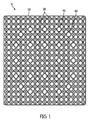
図1〜3は、本発明の一実施形態による燃料アッセンブリ10を示す。図2に示すように、燃料アッセンブリ10は、フレーム25によって支持される複数の燃料エレメント20を備えている。
1-3 illustrate a
図3に示されるように、フレーム25は、炉心隔壁30、ガイド管40、上部ノズル50、下部ノズル60、下部タイプレート70、上部タイプレート80及び/又はアッセンブリ10が原子炉において燃料アッセンブリとして動作可能となるようなその他の構造を備えている。種々の実施形態においては,フレーム25のこれらの構成要素うち単数又は複数を、本発明の範囲から外れることなく省略できる。
As shown in FIG. 3, the
図3に示すように、炉心隔壁30は、上部ノズル50及び下部ノズル60が搭載される。下部ノズル60(又は,アッセンブリ10のその他の適切な構造)は、アッセンブリ10及び炉90の間に流体連結インターフェースを提供するように構築及び形成される。流体連結インターフェースにはアッセンブリ10が配置され、冷却材がアッセンブリ10を介し下部ノズル60を通って炉心に流れ込むようになっている。上部ノズル50は、加熱された冷却材がアッセンブリ10から発電所の(PWR(加圧水型原子炉)の)蒸気発生器、(BWR(沸騰水型原子炉)の)タービン等に流れるのを可能にする。ノズル50、60は、炉心内部構造に適切に結合するように特に設計された形状である。
As shown in FIG. 3, the
図3に示されるように、下部タイプレート70及び上部タイプレート80は、好ましくは、しっかりと(例えば、溶接、ボルト、ネジ等の適切な留め具によって)、炉心隔壁30又は下部ノズル60に(及び/又はアッセンブリ10のその他の適切な構造物に)搭載されている。
As shown in FIG. 3, the
エレメント20の軸方向の下端は、エレメント20を支持し、エレメント20間のスペースを維持できるように、下部タイプレート70の孔70aに適合するピン20aを形成する。ピン20aは、エレメント20がその軸周りで回転するのを防ぐ態様で、又は,下部タイプレート70に対して軸方向に動くのを防ぐような態様で,孔70aに搭載される。このような回転の規制は、隣接するエレメント20の全ての接触点がエレメント20に沿って同じ軸上の位置で(例えば、後述する自己空間面において)確実に発生するのを助ける。ピン20aと孔70aの結合は、溶接、相互作用適合(interference fit)、回転を防止する非円筒状の特徴の一致(例えば、鍵穴及びスプライン(spline))、及び/又は前記以外のエレメント20の下部タイプレート70に対する軸方向及び/又は回転方向の動きを規制する任意の機構によって実現することができる。下部タイプレート70は、軸方向に伸びるチャネル(例えば、開口グリッド(a grid of openings))を含む。冷却材は、このチャネルを通り、エレメント20に流れる。
The lower end in the axial direction of the
エレメント20の軸方向の上端は、エレメント20間の空間の維持を助けつつ、上部ピン20aが、上部タイプレート80に対して、自由に軸方向上方に移動できるように、自由に上部タイプレート80の孔80aに嵌るピン20aを形成する。その結果、エレメント20は、核分裂時、軸方向に成長し、引き伸ばされたエレメント20は、自由に上部タイプレート80内に伸びることができる。
The upper axial end of the
図4に示されるように、ピン70aは、エレメント20の中心部に遷移する。
As shown in FIG. 4, the pin 70 a transitions to the center of the
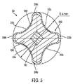
図4及び5は、アッセンブリ10の個々の燃料エレメント/棒20を示す。図5に示されるように、燃料エレメント20の引き伸ばされた中心部は、4つの分葉を持つ断面となる。エレメント20の断面は、実質的に、エレメント20の長さ全体で、均一のままである。各燃料エレメント20は、燃料カーネル100を有する。燃料カーネル100は、高融点金属及び核分裂性物質を含む燃料物質を含む。
4 and 5 show the individual fuel elements /
高融点金属を備える制御材110は、燃料カーネル100の中心の長さ方向の軸に沿って配置される。制御材110は、制御材110を設けない場合にかかる空間を占めることになる核分裂性物質を除去することによって,燃料エレメント20の最も肉厚な部分の中心の温度を制限し,燃料エレメントの表面に沿った熱流束のばらつきを最小化する助けとなる。種々の実施形態においては、制御材110を完全に除去してもよい。
図5に示されるように、燃料カーネル100は、高融点金属被覆材120によって囲まれる。被覆材120は、好ましくは、カーネル100の放射線誘導性の膨張に、欠陥なく(カーネル100を被覆材120の外部環境に露出することなく)耐えることができるほど厚く、強く、柔軟である。単数又は複数の実施形態において、被覆材120全体は、少なくとも0.3mm、0.4mm、0.5mm、及び/又は0.7mmの厚さである。単数又は複数の実施形態において、膨張による欠陥、酸化による欠陥、及び/又は前記以外の被覆材120の欠陥メカニズムの可能性を減らすため、被覆材120の厚みは、少なくとも0.4mmである。
As shown in FIG. 5, the
被覆材120は、(図4に示されるように)カーネル100の軸方向/長さ方向の長さにわたって、環方向に(すなわち、図5の断面図に示されるように、被覆材120の周囲に)実質的に均一な厚みを有していてもよい。また、図5に示されるように、単数又は複数の実施形態において、被覆材120は、分葉20b間の凹交差部/領域20cより、分葉20bの頂点において厚い。例えば、単数又は複数の実施形態において、分葉20bの頂点の被覆材120は、凹交差部/領域20cの被覆材120より、少なくとも10%、20%、30%、40%、50%、60%、70%、80%、90%、100%、125%、及び/又
は150%厚い。分葉20bの頂点の被覆材120をより厚くすることにより、分葉20bの頂点の摩擦抵抗を改良することができる。ここで、隣接する燃料エレメント20は、後述する自己空間平面で互いに接触する。
The dressing 120 is circumferential (ie, as shown in the cross-sectional view of FIG. 5) around the dressing 120 over the axial / length length of the kernel 100 (as shown in FIG. 4). B) may have a substantially uniform thickness. Also, as shown in FIG. 5, in one or more embodiments, the dressing 120 is thicker at the apex of the
本発明の単数又は複数の実施形態において、制御材110で使用される高融点金属、燃料カーネル100、及び被覆材120は、ジルコニウムを有する。本明細書で使用されるように、ジルコニウムという用語は、純ジルコニウム又はその他の合金物質と組み合わせたジルコニウムを意味する。しかしながら、本発明の範囲から外れることなく、その他の高融点金属(例えば、ニオブ、モリブデン、タンタル、タングステン、レニウム、チタニウム、バナジウム、クロム、ジルコニウム、ハフニウム、ルテニウム)を、ジルコニウムの代わりに使用することができる。ここで使用されるように、「高融点金属」の用語は、金属/合金のいずれかであって、1800℃(2073K)より大きな融点を有していることを意味する。
In one or more embodiments of the present invention, the refractory metal used in the
さらに、ある実施形態においては、高融点金属は、アルミニウム等の前記以外の非燃料金属とともに配置されていてもよい。しかしながら、非耐熱性の非燃料金属の使用は、低温で動作する炉心(例えば、約1メートルの高さで、100MWe以下の小さな炉心)に最も適している。高融点金属は、より高い動作温度で使用されることが好ましい。 Further, in some embodiments, the refractory metal may be disposed together with a non-fuel metal other than the above, such as aluminum. However, the use of non-heat resistant non-fuel metals is most appropriate for cores operating at low temperatures (eg, small cores of about 1 meter high and 100 MWe or less). Refractory metals are preferably used at higher operating temperatures.
図5に示されるように、燃料カーネル100及び被覆材120の中心部は、らせん状のスペーサーリブ130の四分葉の輪郭である。制御材110は、リブ130で外方に突出するように形成されてもよい(例えば、四角形の制御材110の角がリブ130と一致するように形成される)。燃料エレメント20は、本発明の別の実施形態において、本発明の範囲から外れることなく、これより多い数の又はより少ない数のリブ130を持っていてもよい。例えば、米国特許出願公開第2009/0252278号公報の図5において一般的に示されるように、燃料エレメントは、好ましくは相互に等しく周辺に間隔をあけた3つのリブ/分葉を持っていてもよい。分葉/リブ130の数は、少なくとも部分的に、燃料アッセンブリ10の形状に依存する。例えば、四分葉エレメント20は、(例えば、AP−1000で使用されえるように)四角の断面形状の燃料アッセンブリ10とよく適合する(work well with)。これに対し、三分葉の燃料エレメントは、(例えば、VVERで使用されるように)六角形の燃料アッセンブリとよく適合する。
As shown in FIG. 5, the center of the
図9は、単数又は複数の実施形態による燃料エレメント20の各部の寸法を示す。単数又は複数の実施形態において、後述のテーブルで特定される大きさ、パラメータ、及び/又は範囲は、いずれも、本発明の範囲から外れることなく、5%、10%、15%、20%、25%、30%、40%又は50%以上増加又は減少することができる。

図4に示されるように、制御材110は、リブ130と位置合わせされる四角形の角を有する真四角形の断面形状である。制御材110は、リブ130のらせん状に続くように、燃料カーネル100の軸の長さに沿って、リブ130と位置合わせされながら、らせん状を形成する。リブ130が多い又は少ない別の実施形態において、制御材110は、好ましくは、エレメント20のリブに応じた辺を有する正多角形の形状を有する。
As shown in FIG. 4, the
図6に示されるように、エレメント20の中央部の断面積は、好ましくは、実質的に、四角形200の面積より小さい。四角形200の一辺は、各リブ130の頂点の接線である。より包括的に説明すると、リブを有するエレメント20の断面積は、好ましくはn個の辺を有する正多角形の面積より小さい。ここで、各リブ130の頂点に、正多角形は接線となる。種々の実施形態において、エレメント20の面積と四角形(又は、4つのリブ130よりも多くの又は少ない数のリブを有するエレメント20の関連する正多角形)の面積との比率は、0.7、0.6、0.5、0.4、0.35、0.3である。図1に示されるように、この面積比率は、炉心隔壁30の利用可能なスペースが、燃料エレメント20によってどれだけ占められるかを概算する。より低い面積比率は、冷却材がより大きな空間で利用可能であることを意味する。冷却材は、中性子減速材として動作し、減速材と燃料の比率(中性子に重要)は、水力学的抵抗(hydraulic drag)を減らし、エレメント20から冷却材への熱の移動を増加させる。種々の実施形態において、結果として生じる減速材と燃料の比率は、(従来の、円筒状の酸化ウラン棒が使用されるときの1.96に対して)少なくとも、2.0、2.25、2.5、2.75、及び/又は3.0である。同様に、種々の実施形態において、燃料アッセンブリ10の流量範囲は、円筒状の酸化ウラン棒を使用する単数又は複数の従来の燃料アッセンブリの使用に対して、16%大きく増加する。増加した流量範囲は、アッセンブリ10を通じて、(従来の酸化ウランアッセンブりに比較して)冷却材の圧力の低下を減らすことができる。これは、冷却材をアッセンブリ10を通じてくみ上げることに関して利点を有する。
As shown in FIG. 6, the cross-sectional area of the central portion of the
図4に示されるように、エレメント20は軸方向に引き伸ばされる。実施形態に示されるように、各エレメント20は、全長(full−length)のエレメントであり、下部タイプレート70は、アッセンブリ10の底部又はその周辺からアッセンブリ10の又はその周辺の上部タイプレート80への全長に亘って伸びる。種々の実施形態又は原子炉の設計において、このことは、どこにおいても1m(小さな原子炉))から4m以上の長さのエレメント20を生じる。したがって、典型的な原子炉では、エレメント20は、1〜5mの長さである。しかしながら、エレメント20は、本発明の範囲から外れることなく、その他の大きさの原子炉に対応するように長くし又は短くすることができる。
As shown in FIG. 4, the
このエレメント20は全長であり、エレメント20は、また、複数の区画で全長エレメントをなすように、区画されていてもよい。例えば、4つの1mのエレメント区画20は、有効に全長エレメントを生成するように端から端まで位置合わせされていてもよい。追加タイプレート70、80は、軸方向の空間を維持する区画と区画の配置の交差部において提供される。
The
単数又は複数の実施形態において、燃料カーネル100は、高融点金属/合金と燃料物質の組み合わせを備える。高融点金属/合金は、ジルコニウム合金を備えていてもよい。燃料物質は、低濃縮ウラン(例えば、U−235(ウラン−235)、U−233)、プルトニウム、又は後述のような低濃縮ウランと組み合わされたトリウム及び/又はプルトニウムを備えていてもよい。ここで使用されるように、「低濃縮ウラン」という用語は、20%未満の重量の核分裂性物質(例えば、U−235又はU−233)を含む全燃料物質を意味する。種々の実施形態において実施形態において、ウラン燃料物質は、U−235の重量において、1%と20%の間、5%と20%の間、10%と20%の間、及び/又は15%と20%の間の濃縮である。単数又は複数の実施形態において実施形態において、燃料物質は、19.7%に濃縮されたU−235を備える。
In one or more embodiments, the
種々の実施形態において実施形態において、燃料物質は、体積分率が3〜10%、10〜40%、15〜35%、及び/又は20〜30%の燃料カーネル100を備えていてもよい。種々の実施形態において、高融点金属は、60〜99%、60〜97%、70〜97%、60〜90%、65〜85%、及び/又は70〜80%の体積分率の燃料カーネル100を備えていてもよい。単数又は複数の実施形態において、体積分率がこれらの範囲の少なくとも一つ内にある場合に、特定の合金の構造の物質相ダイアフラムで定義される有利な特性を有する合金が提供される。燃料カーネル100は、δ相UZr2又はδ相UZr2とa相Zrの組み合わせを備える、高合金燃料であるZr−U合金(すなわち、ウラン成分より比較的高濃度の合金成分)を備えていてもよい。単数又は複数の実施形態において、U−Zrの二元合金系のδ相は、燃料カーネル100の約65−81体積%のジルコニウム成分(約63〜80原子百分率)の範囲であってもよい。これらの実施形態の単数又は複数においては、燃料エレメント20が低体積で(low volumetric)、その燃料エレメント20に対して放射線照射によって膨張が引き起こされる。単数又は複数のそのような実施形態において、分裂ガスは、金属カーネル100に取り込まれる。燃料エレメント20の単数又は複数の実施形態は、従来の燃料エレメント20からのガスギャップを省略できる。単数又は複数の実施形態において、低合金(a相のみの)構造が用いられた場合、そのような膨張が発生することは少ない(例えば、低合金a相U−10Zr燃料が用いられた場合、単位原子百分率の燃焼度ごとに少なくとも10%、20%、30%、50%、75%、100%、200%、300%、500%、1000%、1200%、1500%、又はこれ以上の体積百分率の減少となる)。本発明の単数又は複数の実施形態において、燃料エレメント20又はカーネル100の放射線照射による膨張は、単位原子百分率の燃焼度あたり,20体積%、15体積%、10体積%、5体積%、4体積%、3体積%、及び/又は2体積%未満である。単数又は複数の実施形態において、膨張は,単位原子百分率の燃焼度ごとに体積%で1程度であることが期待される。
In various embodiments, the fuel material may comprise a
単数又は複数の本発明の別の実施形態において、燃料カーネルは、上述のU−Zr燃料カーネル100と同じ又は類似の体積%のプルトニウム−ジルコニウム二元合金、又は、上述のU−Zr燃料カーネル100とは異なる体積%のものに置き換えられる。例えば、カーネル100におけるプルトニウム分率は、実質的に、対応するウランベースカーネル100における対応するウラン分率より小さくてもよい。なぜなら、プルトニウムは、典型的に、核分裂同位体(fissile isotopes)の約60〜70%の重量分率を有しており、LEUウランは、核分裂性U−235同位体の20%以下の重量分率を有しているからである。種々の実施形態において、カーネル100におけるプルトニウム体積分率は、隣接する高融点金属の体積分率で15%、10%及び/又は5%未満であってもよい。
In another embodiment or embodiments of the invention, the fuel kernel is the same or similar volume% plutonium-zirconium binary alloy as the
本発明の単数又は複数の実施形態による高合金カーネル100の使用は、放射線照射時の分裂ガスの有利な残留(advantageous retention)になることがある。酸化燃料及び低合金金属燃料は、典型的に、充分な分裂ガスを放出するが,このガスの放出は、通常は燃料棒のプレナム(plenum)に放出された分裂ガスを含有させることにより,で燃料構造によって調整される。これとは対照的に,本発明の単数又は複数の実施形態による燃料カーネル100は、分裂ガスを開放しない。これは、燃料カーネル100の低動作温度,及び,分裂ガス原子(特に、Xe及びKr)が固体核分裂性物のように振舞うという事実に少なくとも部分的に基づくものである。単数又は複数の実施形態において、分裂ガスの気泡形成及び粒子境界に沿った燃料カーネル100外への移動は起きない。単数又は複数の実施形態において、充分に高い温度で、小さな(数ミクロンの径の)分裂ガスの気泡が形成される。しかしながら、本発明の単数又は複数の実施形態において、これらの気泡は、燃料カーネル100内に隔離されており、分裂ガスの開放を容易にする相互接続したネットワークを形成しない。燃料カーネル100と被覆材120の冶金による接着は、分裂ガス開放の追加の障壁を提供する。
The use of a
種々の実施形態において、単数又は複数の燃料エレメント20の燃料カーネル100(又は、被覆材120又は、燃料エレメント20のその他の適切な部分)は、ガドリニウム、ホウ素、エルビウム、その他の適切な中性子吸収物質のような可燃性中性子吸収物質と合金化され、統合可燃性中性子吸収物質燃料エレメントを形成する。燃料アッセンブリ10の異なる燃料エレメント20は異なる可燃性中性子吸収物質及び/又は異なる量の可燃性中性子吸収物質を利用する。例えば、燃料アッセンブリ10の燃料エレメント20の一部(例えば、75%未満、50%未満、20%未満、1〜15%、1〜12%、2〜12%等)は、25、20、及び/又は15重量%以下(例えば、1〜25重量%、1〜15重量%、5〜15重量%等)のGdを有するカーネル100を含む。燃料アッセンブリ10のその他の燃料エレメント20(例えば、10〜95%、10〜50%、20〜50%、Gdを利用する燃料エレメントより多くの燃料エレメント20)は、10又は5重量%以下(0.1〜10.0重量%、0.1〜5.0重量%等)のErを有するカーネル100を含む。
In various embodiments, the fuel kernel 100 (or cladding 120 or other suitable portion of the fuel element 20) of the
種々の実施形態において、カーネル100で可燃性中性子吸収物質を含まない燃料エレメント20に対して、可燃性中性子吸収物質は(高融点金属よりむしろ)燃料物質を置換する。例えば、カーネル100が65体積%のジルコニウム及び35体積%のウランを含み、可燃性中性子吸収物質を含まない燃料エレメント20の実施形態において、燃料エレメント20は、16.5体積%のGd、65体積%のジルコニウム、及び18.5体積%のウランを含むカーネル100を含む。単数又は複数のその他の実施形態において、可燃性中性子吸収物質は、燃料物質よりも高融点金属を置換する。単数又は複数のその他の実施形態において、燃料カーネル100の可燃性中性子吸収物質は、高融点金属及び燃料物質をその割合に応じて置換する。したがって、これらの種々の実施形態において、燃料カーネル100の可燃性中性子吸収物質は、可燃性中性子吸収物質の存在によってこれらの物質が配置されたUZr2合金又はZr合金の相を変化させないように、δ相のUZr2又はa相のZrのなかに配置されていてもよい。
In various embodiments, for a
可燃性中性子吸収物質を有するカーネル100を有する燃料エレメント20は、炉心で使用される単数又は複数の燃料アッセンブリ10燃料エレメント20の一部をなす(例えば、0〜100%、1〜99%、1−50%等)。例えば,可燃性中性子吸収物質を有する燃料エレメント20は、動作サイクルの早い段階で、電力分配制御を提供するため、及び、溶解ホウ素濃度を減らすため、可燃性中性子吸収物質を有さない燃料エレメント20を含むアッセンブリ10の燃料アッセンブリ格子内の適した場所に配置されていてもよい。同様に、可燃性中性子吸収物質を有する燃料エレメント20を含む選択燃料アッセンブリ10は、動作サイクルの早い段階で、電力分配制御を提供するため、及び、溶解ホウ素濃度を減らすため、可燃性中性子吸収物質を有する燃料エレメント20を含まないアッセンブリ10に対して、炉心の最適な場所に配置されていてもよい。かかる統合可燃性吸収体を使用することによって、動作寿命を容易に延長することができるようになる。
A
追加的に及び/又は代替的に、可燃性中性子吸収物質棒を有する分離非燃料は、(例えば、燃料エレメント20に隣接し、単数又は複数の燃料エレメント20に代わり、制御棒を受け付けない燃料アッセンブリ10のガイド管に挿入され)、燃料アッセンブリ10に含まれていてもよい。単数又は複数の実施形態において、そのような非燃料可燃性中性子吸収物質棒は、バブコックアンドウィルコックス(Babcock and Wilcox)又はウェスティングハウス(Westinghouse)が設計した炉で使用されるものに類似するスパイダーアッセンブリの形状に構成することができる(可燃性中性子吸収物質棒アッセンブリ(BPRA)という)。これらは、制御棒ガイド管に挿入され、選択燃料アッセンブリ10に固定される。ここで、反応制御の動作の最初のサイクルのための制御バンク(banks)は存在しない。可燃性中性子吸収物質群が使用される場合、燃料アッセンブリが次の燃料サイクルに再配置されると、可燃性中性子吸収物質群は取り除かれる。可燃性中性子吸収物質棒を有する分離非燃料が単数又は複数の燃料エレメント20の代わりに配置される別の実施形態において、非燃料可燃性中性子吸収物質棒は、燃料アッセンブリ10内に残り、燃料アッセンブリ10が利用不能となると、その他の燃料エレメント20とともに排出される。
Additionally and / or alternatively, a separate non-fuel having a combustible neutron absorber rod (e.g., a fuel assembly that is adjacent to the
燃料エレメント20は、粉末冶金共押出を通じて製造される。典型的に、燃料カーネル100の粉末高融点金属及び粉末金属燃料物質(カーネル100に含まれる場合は、粉末可燃性中性子吸収物質であってもよい)は混合され、制御材110の空白は、粉末の混合内に配置され、粉末と制御材110の組み合わせは、(例えば、混合を焼結するために種々の時間間隔で様々な温度に加熱された型のなかで)燃料炉心ストック/ビレット(billet)に押圧され、焼結される。制御材110の空白は、最終的に形成される制御材110と同じ又は類似の断面形状を有していてもよい。また、制御材110の空白は、押出により、制御材110の意図される断面形状に変形するように設計された形状を有していてもよい。(制御材110及び焼結燃料カーネル100物質を含む)燃料炉心ストックは、封止された管基部を有し、開口した他端部を有する中空被覆材120管に挿入される。他端部の開口は、ビレットを形成するために、被覆材と同じ物質で製造された端部プラグによって封止される。ビレットは、円筒状に形成されてもよく、例えば、図5及び図9に示されるように、エレメント20の最終的な断面積により近い形状に形成されてもよい。ビレットは、最終的に形成されるカーネル100、被覆材110、及び制御材120を含み、エレメント20を製造するためにセットされた型により、温度及び圧力のもと共押出される。非円筒状の制御材110を利用する種々の実施形態において、ビレットは、制御材110の角が燃料エレメント20の分葉20bと一致するように、押出プレス型に対して適切に方向付けられてもよい。押出処理は、直接押出(すなわち、固定型を通じてビレットを動かす)又は非直接押出(すなわち、固定ビレットに対して、型を動かす)のどちらかで実行される。この処理により、燃料カーネル100と冶金接着された被覆材120が得られる。この被覆材120は、燃料カーネル100からの被覆材120の剥離のリスクを減らす。被覆材120の管と端部プラグは互いに冶金接着され、被覆材120の燃料カーネル100を封止する。高融点金属の高い融点は、粉末冶金をこれら金属から加工エレメントを選択する方法とすることを意図する燃料エレメント10で使用される。
The
単数又は複数の別の実施形態において、燃料エレメント20の燃料炉心ストックは、焼結の代わりに、鋳造によっても製造できる。粉末の又は一体の(monolithic)高融点金属及び粉末の又は一体の燃料物質(カーネル100に含まれる場合は、粉末可燃性中性子吸収物質であってもよい)は混合され、型に鋳造される。型は、鋳造カーネル100に制御材−空白−形成ボイドを生成する。制御材110の空白が、カーネル100が鋳造されたあとに、押し出されるビレットを形成するように被覆材120が追加されるのと同様に、挿入される。燃料エレメント20を製造する残りのステップは、鋳造の代わりに焼結を利用する上述の実施形態と同じ又は類似のままでよい。後に続く押出により、制御材110とカーネル100の間及びカーネル100と被覆材120の間の冶金接着が得られる。
In one or more alternative embodiments, the fuel core stock of the
単数又は複数の別の実施形態において、燃料エレメント20は、粉末金属燃料物質の代わりに、粉末セラミック燃料物質を利用して製造される。残りの製造ステップは粉末金属燃料物質を用いる実施形態に関する上述のものと同じであってよい。種々の金属燃料の実施形態及びセラミック燃料の実施形態において、製造プロセスにより、金属非燃料物質のマトリクスに配置された燃料物質を備える燃料カーネル100を得ることができる。単数又は複数の金属燃料の実施形態において、結果物である燃料カーネル100は、金属燃料物質の合金及び金属非燃料物質のマトリクス(例えば、ウラン−ジルコニウム合金)を備える金属燃料合金カーネルを備える。単数又は複数のセラミック燃料の実施形態において、カーネル100は、金属非燃料物質のマトリクスに(例えば、全体に分散され)配置される燃料物質を備える。種々の実施形態において、製造プロセスで使用されるセラミック燃料物質は、粉末ウラン又は酸化プルトニウム、粉末ウラン又は窒化プルトニウム、粉末ウラン又は炭化ルトニウム、粉末ウラン又は水素化プルトニウム、又はそれらの組み合わせを備えていてもよい。管にUO2ペレットが配置される従来のUO2燃料エレメントに対して、本発明の単数又は複数の実施形態による製造方法により、非燃料物質の固体マトリクス(例えば、ジルコニウムマトリクス)に配置されるセラミック燃料を得ることができる。
In one or more alternative embodiments, the
図4に示すように、らせん状リブ130の軸方向のコイルピッチは、燃料エレメント断面における対角距離に等しい間隔で配置された近接する燃料エレメント10の軸の配置の状態に応じて選択され、燃料エレメントの長さの5%から20%である。一実施形態において、ピッチ(すなわち、分葉/リブが一回りする軸方向の長さ)は、約21.5cmであり、エレメント20の全活動長さは、約420cmである。図3に示されるように、底部で下部タイプレート70によって、頂部で上部タイプレート80によって、及び炉心の高さに対して、炉心隔壁30によって、燃料エレメント10は、縦方向の配置の安定性が提供される。図1に示されるように、燃料エレメント10は、隣接するいずれか2つの燃料エレメント10が、少なくとも燃料エレメントの束のひとつの断面で、2つの隣接する燃料エレメント10の軸を通過する対称な共通の面を有するように周方向の向きを有している。
As shown in FIG. 4, the axial coil pitch of the
図1に示されるように、燃料エレメント20のらせん状の捻じれは、その向きとともに、単数又は複数の自己空間を確保する。図1に示されるように、そのような自己空間平面において、隣接するエレメント20のリブは、相互に接触して、エレメント20間に適切な空間を確保する。したがって、エレメント20の中心間の空間は、各エレメント20の角間の幅とほぼ同じとなる(図5で示されたエレメントでは、12.6mmである)。各燃料エレメント20の分葉20bの数と、燃料エレメント20のそれぞれの幾何学的配置によって、全ての隣接する燃料エレメント20又は隣接する燃料エレメント20の一部だけが、接触することとなる。例えば、四分葉の実施形態に示されるように、各燃料エレメント20は、各自己空間平面において、4つの全ての燃料エレメント20と接触する。しかしながら、燃料エレメントが、亀甲に配列される三分葉の燃料エレメントの実施形態では、各燃料エレメントは、与えられた自己空間平面において、6つの隣接する燃料エレメントのうち3つとだけ接触することとなる。三分葉の燃料エレメントは、次の軸方向の空間の自己空間平面において(すなわち、先の自己空間平面からの回転オフセットの1/6)、その他の3つの燃料エレメントと接触することとなる。
As shown in FIG. 1, the helical twist of the
n個の燃料エレメントが特定の燃料エレメント20に隣接するn分葉のエレメント20において、自己空間平面は、1/nらせん回転毎に存在する。(例えば、4つの他の燃料エレメントが隣接する四角形パターンに配置された四分葉エレメント20における1/4らせん回転ごと、3つの他の燃料エレメントが隣接する3角形パターンに配置された三分葉エレメント20における1/3らせん回転ごと(すなわち、燃料エレメントの周囲で120度ごと)である)。らせんのピッチは、燃料エレメント20の軸方向長さに亘って、より多くの又はより少ない自己空間平面を生成するために変化してもよい。一実施形態において、各四分葉燃料エレメント 20は、燃料エレメント20の束の軸方向長さに亘って複数の自己空間平面が存在するように、複数の捻じれを有する。
In an n-
ここで示された実施形態において、全てのエレメント20は同じ方向に捻じれている。しかしながら、別の実施形態において、本発明の範囲から外れることなく、隣接するエレメント20は反対の方向に捻じれていてもよい。
In the embodiment shown here, all
燃料棒に沿う自己空間平面数の式は以下のとおりである。
N=n*L/h
ここで、Lは、燃料棒の長さ、nは、分葉 (リブ)の数及びある燃料エレメントに隣接する燃料エレメントの数、hは、らせん捻じれのピッチである。 この式は、分葉の数と隣接燃料エレメントの数が同じでない場合には、わずかに異なる。
The formula for the number of self-space planes along the fuel rod is:
N = n * L / h
Here, L is the length of the fuel rod, n is the number of leaflets (ribs) and the number of fuel elements adjacent to a certain fuel element, and h is the pitch of the helical twist. This equation is slightly different when the number of lobes and the number of adjacent fuel elements are not the same.
自己空間の結果、燃料アッセンブリ10は、アッセンブリ10の長さに沿って適切なエレメント空間を確保する必要があるスペーサグリッドを省略することができる。スペーサグリッドを無くすることにより、冷却材は、アッセンブリ10を、より自由に流れることができる。アッセンブリ10は、有利に、エレメント20から冷却材への熱移動を増加する。しかしながら、本発明の別の実施形態において、アッセンブリ10は、本発明の範囲から外れることなく、スペーサグリッドを含む。
As a result of self-space, the
図3に示されるように、炉心隔壁30は、燃料エレメント20の全長に沿って軸方向に伸び、エレメント20を囲む管状シェルを形成する。しかしながら、本発明の別の実施形態において、炉心隔壁30は、燃料エレメント20を囲む軸方向空間バンド(axially−spaced bands)を有していてもよい。単数又は複数のそのようなバンドは、軸方向に、自己空間平面と一致する。軸方向に伸びる角支持部は、バンドを支持し、バンドの位置を維持し、アッセンブリを強化するため、そのような軸方向の空間バントの間に伸びてもよい。その代わり及び/それに加えて、孔が、支持のため、炉心隔壁30が必要又は望まれていないような場所で、異なった管状/多角形状の炉心隔壁30に切り込まれていてもよい。全炉心隔壁30の使用は、分離冷却材が各燃料アッセンブリ10を流れるのに対してより優れた制御を容易に行うことができる。逆に、バンド又は孔を有する炉心隔壁の使用は、冷却材の隣接する燃料アッセンブリ10とよりよい混合を容易にすることができる。隣接する燃料アッセンブリ10間の冷却材の温度勾配を減らす効果がある。
As shown in FIG. 3, the
図1に示すように、炉心隔壁30の断面周囲は、アッセンブリ10が使用される炉を収容する形状となっている。AP−1000のような四角形の燃料アッセンブリを使用する炉において、炉心隔壁は、四角形の断面を有する。しかしながら、炉心隔壁30は、また、使用される炉によって、適切などのような形状を有することもできる(例えば、VVER炉で使用される六角形状(例えば、米国特許出願第2009/0252278号の図1に示される。))。
As shown in FIG. 1, the periphery of the cross section of the
ガイド管40は、炭化ホウ素(B4C)、銀‐インジウム‐カドミウム(Ag,In,Cd)、チタン酸ジスプロシウム(Dy2O3・Ti02)又はその他の適切な合金又は反応制御で使用される物質(不図示)及び炭化ホウ素、酸化ガドリニウム(Gd203)又はその他の適切な物質(不図示)に基づき、制御吸収体の挿入を提供し、軸方向に弾性変位可能な上部ノズル50に配置される。ガイド管40は、ジルコニウム合金を備える。例えば、図1に示されるガイド管40の配置は、AP−1000炉で使用される配置である(例えば、24個のガイド管が、17×17のグリッドに示される部分で2つの環状列に配置される。)。
The
フレーム25の形状、大きさ、特徴は、アッセンブリ10が使用される特定の炉心に依存する。当業者は、適切な形状及び大きさとした燃料アッセンブリ10のフレームをどのように製造するのか理解できるであろう。例えば、フレーム25は、従来の発電所の炉心の酸化ウラン又は混合酸化燃料アッセンブリに代わる炉心に適合するように形成され、構成されてもよい。原子力発電所は、2010以前に実際に使用されていた炉心設計(例えば、2,3又は4−ループPWR、BWR−4)を備えることができる。また、原子力発電所は、特に燃料アッセンブリ10での使用のため全く新しい設計であってもよい。
The shape, size, and characteristics of the
上述のように、説明された燃料アッセンブリ10は、AP−1000又はEPR炉で使用するために設計される。アッセンブリは、燃料エレメント20の17×17配列を含み、24個の燃料エレメント20は、上述の通り、EPRにおける合計265個の燃料エレメント20又はAP−1000における264個の燃料エレメント20のため、ガイド管40と置換される(AP−1000においては、ガイド管と置換される24個の燃料エレメントに追加して、中央の燃料エレメントは、インストルメント管(instrumented tube)と置換される。)。
As described above, the described
エレメント20は、好ましくは、燃料アッセンブリ10の全核分裂性物質の100%を提供する。または、アッセンブリ10の核分裂性物質のいくつかは、エレメント20以外の燃料エレメント(例えば、分葉を有しない燃料エレメント、酸化ウランエレメント、エレメント20とは異なる燃料比及び/又は濃縮を有するエレメント)により提供されてもよい。種々の別の実施形態において、燃料エレメント20は、燃料アッセンブリ10の全核分裂の、少なくとも50%、60%、70%、75%、80%、85%、90%、及び/又は95%の量を提供する。
本発明の単数又は複数の実施形態による金属燃料エレメント20の使用は、ウェスティングハウスが設計したAP−1000、AREVAが設計したEPR炉のような(沸騰水型原子炉及び加圧水型原子炉を含む)軽水原子炉(LWR)で従来使用されていた酸化ウラン又は混合酸化燃料を超えた利点をもたらす。例えば、単数又は複数の実施形態において、現在既存のLWR又は新しいLWRで使用されている従来提案されていた標準的な酸化ウラン燃料及び燃料アッセンブリの代わりに、全金属燃料エレメント20及び/又は燃料アッセンブリ10を用いることにより、標準的な酸化ウラン又は混合酸化燃料で動作するLWRの電力定格は約30%までの割合で増加する。
Use of the
標準的な酸化ウラン燃料で動作するLWRの電力定格の増加の重要な制約のひとつは、燃料が利用する円筒状の燃料エレメントの小さな表面積であった。円筒状の燃料エレメントは、どのようなタイプの燃料エレメント断面輪郭の体積の割合に対しても最も小さな表面積を有している。標準的な酸化ウラン燃料のその他の制約は、燃料エレメントが許容可能な燃料性能基準を満たしている間にも、おそらく達してしまう比較的低い燃焼性であった。結果として、標準的な酸化ウラン又は混合酸化燃料に関連するこれらのエレメントは、既存の炉の電力定格の増加の程度を大きく制限していた。 One of the key constraints on increasing the power rating of LWRs operating with standard uranium oxide fuels was the small surface area of the cylindrical fuel elements utilized by the fuel. Cylindrical fuel elements have the smallest surface area for any type of fuel element cross-sectional profile volume fraction. Another limitation of standard uranium oxide fuel was the relatively low flammability that is likely to be achieved while the fuel element meets acceptable fuel performance standards. As a result, these elements associated with standard uranium oxide or mixed oxide fuels have severely limited the degree of increase in power ratings of existing furnaces.
全金属燃料エレメント20の単数又は複数の実施形態は、上記制限を克服する。例えば、上述のとおり、スペーサグリッドを無くすことにより、水圧耐性を減少し、従って、エレメント20から第1冷却材への冷却材の流れと熱の流れを増加することができる。燃料エレメント20のらせん状の捻じれは、冷却材の混合及び乱流を増加し、また、エレメント20から冷却材への熱の流れも増加する。
One or more embodiments of the all-
予備的中性子解析及び熱水力解析は、本発明の単数又は複数の実施形態による以下のことを示す:
・ LWR炉の熱出力定格は、30.7%以上の割合で増加可能である(例えば、EPR炉の熱出力定格は4.59GWthから6.0GWthまで増加できる)。
・ウラン−ジルコニウム混合での25%のウラン体積分率及び19.7%U−235濃縮で, 四分葉金属燃料エレメント20の構造を有するEPR炉心は、バッチ(batch)毎に(18ヶ月に1度に)72個の燃料アッセンブリが置換されたら、増加した熱出力定格6.0GWthで、約500〜520の定格出力運転日数(EFPD)動作でき、バッチ(batch)毎に(18ヶ月に1度に)80個の燃料アッセンブリが置換されたら、540〜560のEFPDとなる。
・多葉性の燃料エレメントの増加した表面積により、増加した電力定格である6.0GWthであっても、多葉性の燃料エレメント平均的な表面の熱の流れは、4.59GWthの熱出力定格で動作する円筒状の酸化ウラン燃料エレメントより4〜5%低く示される。このことは、重大な熱の流れ(例えば、PWRでの核沸騰率からの増加した逸脱又はBWRでの重大な電力率を制限する最大分率)に関し、増加した安全率(safety margin)を提供する。さらに、このことは、可燃性中性子吸収物質を有する各アッセンブリの12個の燃料エレメントの使用を可能性とする。可燃性中性子吸収物質は、サイクルの始まりでの過度の反応又を取り除き、炉心の加熱時のドップラー効果(Doppler Effect)を増加させるために使用できる。
・ したがって、燃料アッセンブリ10は、従来の酸化ウラン又は混合酸化燃料アッセンブリより低い燃料動作温度で、より大きな熱出力を提供することができる。
Preliminary neutron analysis and thermal hydraulic analysis show the following according to one or more embodiments of the present invention:
The thermal power rating of the LWR furnace can be increased at a rate of 30.7% or more (for example, the thermal power rating of the EPR furnace can be increased from 4.59 GWth to 6.0 GWth).
EPR cores with the structure of a quadrant
• Due to the increased surface area of the multi-leaf fuel element, the heat flow on the average surface of the multi-leaf fuel element is 4.59 GWth, even at an increased power rating of 6.0 GWth. 4-5% lower than the cylindrical uranium oxide fuel element operating at This provides an increased safety margin for significant heat flows (eg, increased deviation from the nucleate boiling rate at the PWR or maximum fraction limiting the critical power rate at the BWR). To do. In addition, this allows the use of twelve fuel elements in each assembly with combustible neutron absorbing material. The combustible neutron absorbing material can be used to remove excessive reactions at the beginning of the cycle and to increase the Doppler Effect when heating the core.
Thus, the
アッセンブリ10の増加した出力を利用するために、従来の発電所(例えば、より広い及び/又は追加の冷却材ポンプ、蒸気発生器、熱交換器、加圧器、タービン)は改善される。確かに、単数又は複数の実施形態において、この改善により、既存の発電所で、30〜40%大きな電力を得ることができる。そのような可能性は、2つめの炉を建設する必要を回避することができる。改修の費用は、増加した電力出力により間もなく支払う(pay)ことができる。また、新しい発電所は、アッセンブリ10のより高い熱出力を扱い、利用するのに適切な特徴を含むように建設することができる。
In order to take advantage of the increased output of
さらに、本発明の単数又は複数の実施形態は、大きな改修を行うことなく、既存の炉システムを使用して標準的な酸化ウラン又は混合酸化燃料を用いた場合と同じ電力定格でLWRが動作するのを可能にする。例えば、一実施形態において:
・ EPRは、従来の酸化ウラン燃料が使用された場合と同じ電力出力を有することとなる。
:4.59 GWt;
・ウラン−ジルコニウムでの25%のウラン体積分率及び約15%U−235濃縮で、四分葉金属燃料エレメント20の構造を有するEPR炉心は、バッチ(batch)毎に72個の燃料アッセンブリが置換されたら、約500〜520の定格出力運転日数(EFPDs)動作でき、バッチ(batch)毎に80個の燃料アッセンブリが置換されたら、540〜560のEFPDとなる。
・エレメント20の平均的な表面の熱の流れは、従来の酸化ウラン燃料の円筒状の棒に比べて約30%の割合で減少する(例えば、39.94 v.57.34 W/cm2)。アッセンブリ10を通じての冷却材の温度上昇(例えば、流入温度と流出温度の違い)及びアッセンブリ10を通る冷却材の流量は、従来の燃料アッセンブリとほぼ同じままであるので、減少した平均的な表面の熱の流れは、重大な熱の流れに関しての安全率の増加に貢献する対応する燃料棒表面温度の減少となる(例えば、PWRでの核沸騰率からの増加した逸脱i又はBWRでの重大な電力率を制限する最大分率)。
Furthermore, the embodiment or embodiments of the present invention operate the LWR at the same power rating as with standard uranium oxide or mixed oxide fuels using existing furnace systems without major modifications. Make it possible. For example, in one embodiment:
EPR will have the same power output as when conventional uranium oxide fuel is used.
: 4.59 GWt;
• An EPR core with a structure of a quadrant
The average surface heat flow of the
それに加えて及び/又はそれの代わりに、本発明の単数又は複数の実施形態の燃料アッセンブリ10は、段階的/はしご的に、従来の燃料アッセンブリの代わりの炉心となる。その過渡期において、従来の燃料アッセンブリとして比較可能な(同等な)核分裂性/中性子性/熱出力を有する燃料アッセンブリ10は、徐々に、そして発電所の動作パラメータは代えることなく、後に続く燃料の変更を経て、そのような従来の燃料アッセンブリと取って代わることができる。したがって、燃料アッセンブリ10は、改造して、既存の炉心に取り付けることができる。このことは、過渡期には重要である(すなわち、燃料アッセンブリ10の可能性を有する炉心でスタートし、徐々に燃料アッセンブリ10の完全な炉心に移行していく。)。
Additionally and / or alternatively, the
さらに、アッセンブリ10の分裂性負荷は、発電所のオペレータが希望する特別な移行にも対応することができる。例えば、各分裂性負荷は、炉の熱出力を増加するため、アッセンブリ10が取って代わる従来の燃料アッセンブリの使用に対して0%〜30%いずれかの又はそれ以上の範囲で、適切に増加することができる。したがって、発電所のオペレータは、改良時の種々のタイミングで、既存の発電所のインフラ又は発電所の能力に基づいて、特定の出力の改良を選択することができる。
In addition, the disruptive load of the
燃料アッセンブリ10及び燃料エレメント20の単数又は複数の実施形態は、本発明の範囲から外れることなく、(軽水炉に対して)高速炉で使用することができる。高速炉において、燃料カーネル100の非燃料金属(非燃料物質)は、好ましくは、高融点金属、例えば、モリブデン合金 (例えば、純モリブデン又はモリブデンとその他の物質との組み合わせ)であり、被覆材120は、好ましくは、ステンレス鋼(その種々の合金を含む)又はそのような炉の冷却材で使用するのに適したその他の物質(例えば、ナトリウム)である。そのような燃料エレメント20は、上述の共押出処理で製造することができ、又は、その他の適切な方法(例えば、真空{しんくう}溶解)によって製造することも可能である。
One or more embodiments of the
図7A、7B、及び8で示されるように、本発明の単数又は複数の実施形態によって、燃料アッセンブリ510は、CANDU炉のような加圧重水炉500(図8参照)で使用することもできる。
As shown in FIGS. 7A, 7B, and 8, according to one or more embodiments of the present invention, the
図7A及び7Bに示されるように、燃料アッセンブリ510は、フレーム520に搭載される複数の燃料エレメント20を備える。フレーム520は、(例えば、via 溶接、静合(interference fit)、エレメント20を下部タイプレート70に取り付ける上述の種々の取り付け方法のいずれかによって)燃料エレメント20の対向する軸方向端部を搭載する2つのエンドプレート520a、520bを備える。燃料アッセンブリ510で使用されるエレメント20は、典型的に、アッセンブリ10で使用されるエレメント20より大幅に短い。種々の実施形態及び炉500によると、炉500で使用されるエレメント20及びアッセンブリ510は約45.72cm(18インチ)の長さである。
As shown in FIGS. 7A and 7B, the
エレメント20は、自己空間平面がエレメント20に空間を維持するように、アッセンブリ10に関し上述した態様でアッセンブリ510で相互に関連して位置することができる。また、アッセンブリ510のエレメント20は、隣接するエレメント20が相互に接触しないように、エレメント20の空間を維持するために、代わりに全体的にフレーム520に依存して、相互に空間を空けていてもよい。また、種々の位置で、隣接するエレメント20に接触し、エレメント空間20を維持するために、エレメント20の軸方向長さに沿って、(例えば、棒空間を維持するために、スペーサが加圧重水炉の従来の燃料アッセンブリの従来の燃料棒で使用されるのと類似の態様で、)スペーサがエレメント20又はそのリブに取り付けられてもよい。
The
図8に示されるように、アッセンブリ510は、炉500のカランドリア管500aに送られる(当該技術分野において、カランドリア500と参照する場合もある)。炉500は、重水500bを減速材及び第1冷却材として用いる。第1冷却材500bは、管500aを通って、熱交換器まで、水平に循環する。熱交換器では、熱が、典型的にはタービンを介して、電力を生成するために使われる第2冷却材のループに移動させられる。燃料アッセンブリ搭載機構(図示せず)は、燃料アッセンブリ510をカランドリア管500の一方に搭載し、管500aの反対側から使用済みアッセンブリ510を押し出す。この動作は,典型的には、炉500を動作させながら行われる。
As shown in FIG. 8, the
燃料アッセンブリ510は、既存の従来の加圧重水炉(例えば、CANDU炉)の従来の燃料アッセンブリ(当該技術分野では、燃料束として知られる)に直接取って代わるように設計されてもよい。このような一実施形態において、アッセンブリ510は従来のアッセンブリ/束に代わる炉500内に送られる。そのような燃料アッセンブリ510は、取って代わられる従来のアッセンブリと類似の中性子/熱特性を有するように設計されてもよい。また、燃料アッセンブリ510は、熱出力の改良を提供するよう設計されてもよい。そのような改良の実施形態において、新たな又は改善された炉500は、より高い熱出力を収容できるように設計できる。
The
本発明の種々の実施形態において、従来の原子炉の従来の燃料アッセンブリに代わるように、燃料アッセンブリ10は設計される。例えば、図1に示される燃料アッセンブリ10は、特に、UO2燃料棒の17×17の配列を利用する従来の燃料アッセンブリに代わるように設計される。アッセンブリ10のガイド管40は、従来の燃料アッセンブリで使用されるのと全く同じ位置に残され、燃料エレメント20の全てが同じ大きさの場合、従来のUO2燃料アッセンブリと燃料アッセンブリ10の単数又は複数の実施形態(例えば、12.6mmピッチ)の間で燃料エレメント/棒間のピッチは変わらない。すなわち、燃料エレメント20の長さ方向の軸は、従来のUO2燃料棒の長さ方向の軸が従来の比較可能な(同等な)燃料アッセンブリ内にある場合と同じ位置に配置される。種々の実施形態において、燃料エレメント20は、比較可能な(同等な)UO2燃料棒より大きな外接径(典型的なUO2燃料棒の外径が9.5mmに対して、例えば、12.6mm)を有してもよい。結果として、図1に示される自己整合平面において、燃料エレメント20に占められる空間の断面長さ及び幅は、従来の燃料アッセンブリの従来のUO2燃料棒のものよりやや大きくてもよい(例えば、燃料アッセンブリ10について214.2mm(例えば、17個の燃料エレメント20×燃料エレメントごとの外接径が12.6mm)、相互に12.6mmピッチで離れた9.5mmのUO2燃料棒の17×17の配列を有する従来のUO2燃料アッセンブリについて211.1mmである)。従来のUO2燃料アッセンブリにおいて、スペーサグリッドは、燃料棒を囲み、従来の燃料アッセンブリ全体の断面積のエンベロープ(envelope)を、214mm×214mmに増加させる。燃料アッセンブリ10において、炉心隔壁30は、同様に、燃料アッセンブリ10の断面積エンベロープを増加させる。炉心隔壁30は、適した厚みである(例えば、0.5mm又は1.0mmの厚さ)。1.0mmの厚みの炉心隔壁30を利用する一実施形態において、燃料アッセンブリ10の一実施形態の全断面積エンベロープは、216.2mm×216.2mmであってもよい(例えば、214mmは17個の12.6mm径の燃料エレメント20に炉心隔壁30の1.0mmの厚みの2倍を追加する)。結果として、本発明の単数又は複数の実施形態に従い、燃料アッセンブリ10は、典型的なUO2燃料アッセンブリ(214mm×214mm)より、わずかに大きくてもよい(例えば、216.2mm×216.2mm)。このより大きな寸法によって、アッセンブリ10は,従来のUO2燃料アッセンブリで使用するために設計された単数又は複数の従来の炉の燃料アッセンブリ位置に適合しにくくなる。このサイズの変化に対応するため、新しい炉は、本発明の実施形態に従って、より大きな寸法の燃料アッセンブリ10を収容するように構成及び建設される。
In various embodiments of the present invention, the
本発明の別の実施形態において、全ての燃料エレメント20の外接径は、燃料アッセンブリ10の全体の断面積を減少するため、わずかに減少することができる。例えば、燃料エレメント20の外接径は、燃料アッセンブリ10によって占められる空間の全断面積が従来の214mm×214mm燃料アッセンブリに比較可能な(相当する)ままであるように、0.13mm〜12.47mmで減少することができる(すなわち、17個の燃料エレメント20の12.47mmの径に2つの炉心隔壁の1.0mmの厚みを足し、合計が約214mmとなる)。17×17の配列の大きさの減少は、従来の燃料アッセンブリでのガイド管位置に対して、燃料アッセンブリ10でのガイド管40の位置をわずかに変える。管40の位置のわずかな変化を収容するため、対応する制御棒配列の位置及び炉における制御棒駆動機構を、同様に、ガイド管40の位置の変化を収容するため移動させる。また、充分なクリアランスと公差が、従来の炉の制御棒に提供される。従来ように配置される制御棒は、燃料アッセンブリ10の管40のわずかな移動に適切に適合できる。
In another embodiment of the present invention, the circumscribed diameter of all
また、周辺の燃料エレメント20の径は、アッセンブリ10全体が従来の燃料アッセンブリのために設計された従来の炉に適合するように、わずかに減らすことができる。例えば外側の行の燃料エレメント20の外接径は、燃料アッセンブリの全体の大きさが214mm×214mm(例えば、15個の12.6mmの燃料エレメント20に、2個の11.5mmの燃料エレメント20と、2個の1.0mmの厚みの炉心隔壁30を足す。)となるように、1.1mmの割合で減らすことができる。また、燃料エレメント20の外側の2行の外接径は、燃料アッセンブリ全体の大きさが214mm×214mm(例えば、13個の12.6mmの燃料エレメント20に、4個の12.05mmの燃料アッセンブリと2個の1.0mmの厚みの炉心隔壁30を足す。)のままであるように、0.55mmの割合で減らすことができる。それぞれの実施形態において、ガイド管40が従来の炉の制御棒の配列及び制御棒駆動機構と一致するように、燃料エレメント20ガイド管40の中央の13×13の配列のピッチと位置は変更されない。
Also, the diameter of the surrounding
図10は、本発明の別の実施形態による燃料アッセンブリ610を示す。 種々の実施形態において、燃料アッセンブリ610は、種々の従来のUO2燃料アッセンブリで使用するように設計された炉の制御棒の位置を維持しつつ、従来の炉の従来のUO2燃料アッセンブリに代わるように設計される。燃料アッセンブリ610は、通常、図1で示し、説明された燃料アッセンブリ10に類似するが、制御棒の位置や制御棒駆動機構を変更することなく、アッセンブリ610が単数又は複数の既存の炉の種類によりよく適合するのを助けるように幾つかの相違を有する(例えば、17×17の配列のUO2棒を利用するウェスティングハウスの燃料アッセンブリの設計を使用する炉)。
FIG. 10 illustrates a
図10に示されるように、燃料アッセンブリは、種別の17×17の配列を有する。中央の15×15の配列は、図1に示す類似の燃料アッセンブリ10に関して上述したとおり、200の燃料エレメント20及び25個のガイド管40によって占められる。特定の炉の設計によって、中央のガイド管40は、炉の設計が中央管40を利用しないものである場合、追加の燃料エレメント20に代えることもできる(すなわち、201個の燃料エレメント20と24個のガイド管40である)。ガイド管40の位置は、従来のUO2燃料アッセンブリで使用するように設計された炉で使用されるガイド管の位置に対応する。
As shown in FIG. 10, the fuel assembly has a 17 × 17 array of types. The central 15 × 15 array is occupied by 200
燃料アッセンブリ610の17×17の配列/パターンの周辺位置(すなわち、横方向に燃料エレメント20から外側に配置された位置)は、64個のUO2燃料エレメント/棒650によって占められる。当該技術分野で知られているように、燃料棒650は、中空棒に配置された標準的なUO2ペレット燃料を備えていてもよい。UO2ペレット燃料は、U−235で、20%未満、15%未満、10%未満、及び/又は5%未満に濃縮されてもよい。棒650は、従来のUO2燃料アッセンブリに配置された空間にアッセンブリ610がより適合するように、燃料アッセンブリ610の断面積寸法全体をわずかに減少させる燃料エレメント20の外接径よりわずかに小さい径(例えば、9.50mm)を有していてもよい 。
Peripheral positions of the 17 × 17 array / pattern of fuel assembly 610 (ie, positions located laterally outward from fuel element 20) are occupied by 64 UO 2 fuel elements /
ここで示された実施形態において、燃料棒/エレメント650は、UO2ペレット燃料を備える。しかしながら、燃料棒/エレメント650は、代わりに、単数又は複数の核分裂性及び/又は核原料物質(例えば、トリウム、プルトニウム、U−235、U−233、それらのいずれかの組み合わせ)のその他の適切な組み合わせを利用してもよい。そのような燃料棒/エレメント650は、金属及び/又は酸化燃料を有していてもよい。
In the embodiment shown here, the fuel rod /
単数又は複数の別の実施形態において、燃料棒650は、64の周辺位置の全てより少ない位置を占める。例えば、周囲の下の行及び右の列は燃料エレメント20に占められ、燃料棒650は、周囲の上の行及び左の列を占めていてもよい。また、燃料棒650は、燃料アッセンブリのその他の2辺を占めていてもよい。炉心隔壁30は、燃料アッセンブリ周辺の追加の燃料エレメント20を囲むために変更されてもよい。そのような変更された燃料アッセンブリは、相互に隣接するように配置されてもよい。ひとつのアッセンブリ周辺の燃料エレメント650の行/列は、常に、隣接する燃料アッセンブリの燃料エレメント20の行/列に隣接する。結果として、燃料アッセンブリの追加の空間が、隣接するアッセンブリのインターフェースがわずかに燃料エレメント650をインターフェース側の周辺に含むアッセンブリに向かって移動するという事実により提供される。そのような変更は、燃料アッセンブリ610が提供するよりも、高い熱出力の燃料エレメント20のより多くの使用を提供することができる。
In another embodiment or embodiments, the
炉心隔壁30は、燃料エレメント20の配列を囲み、エレメント20をエレメント650から分離する。ノズル50、60、炉心隔壁30、それらの間に形成された冷却材の通路、エレメント20及びエレメント650を通じての相対応力低下、及び/又はエレメント650を囲む(後述する)スペーサグリッド660を通じての増加した圧力低下により、炉心隔壁30外で比較的低い熱出力の燃料棒650を過ぎる流量に比べて、炉心隔壁30内でより高い熱出力の燃料エレメント20を通過するより高い冷却材の流量を得ることができる。通路及び/又は通路内の通行口は、相対熱出力と設計された動作温度に基づいて、エレメント20及び650を通過する冷却材の相対流量を最適化するために、設計することができる。
The
種々の実施形態において、燃料アッセンブリ610の燃料エレメント20の減速材と燃料の比率は、2.7、2.6、2.5、2.4、2.3、2.2、2.1、2.0,1.9、及び/又は1.8以下である。ここで示された実施形態において、減速材と燃料の比率は、(1)冷却材/減速材で利用可能な炉心隔壁30内の全面積(これは、例えば、(ガイド管40が冷却材で満たされているとすると)炉心隔壁30の全断面積から、燃料エレメント20によって占められる断面積を引くことによりによって近似される。)と (2)炉心隔壁30の燃料エレメント20のカーネル100の全断面積との比率と等しい。
In various embodiments, the ratio of moderator to fuel in the
本発明の別の実施形態において、炉心隔壁30は、上述のように、単数又は複数の環状のバンドで置換されてもよく、炉心隔壁30の孔と共に提供されてもよい。バンドや炉心隔壁30を使用することにより、燃料エレメント20と燃料エレメント650の間の冷却材の相互混合(cross−mixing)が容易になる。
In another embodiment of the present invention, the
図10で示されたように、燃料エレメント650は、環状のスペーサグリッド660内に配置される。通常は、従来のUO2燃料アッセンブリで使用されるスペーサグリッドの外側部分に相当する。スペーサグリッド660は、炉心隔壁30に(例えば、溶接、ボルト、ネジ、その他の留め具によって)しっかりと連結することができる。スペーサグリッド660は、好ましくは、燃料エレメント650と燃料エレメント20の間に、中央の燃料エレメント20と同じピッチを提供するための大きさ(例えば、全燃料エレメント20及び650の軸の12.6mmのピッチ)とする。そのような空間を提供するため、燃料エレメント650は、炉心隔壁30及びスペーサグリッド660の内側より、スペーサグリッド660の外側の近くに配置することができる。燃料アッセンブリ610及びスペーサグリッド660は、また、好ましくは、隣接する燃料アッセンブリの燃料エレメント650の間に同じピッチ(例えば、12.6mmのピッチ)を提供できるような大きさ及び位置とされる。しかしながら、燃料エレメント20及び650のいずれかの間の空間は、本発明の範囲から外れることなく、その他の燃料エレメント20、650の間の空間に対して変化することができる。
As shown in FIG. 10, the
種々の実施形態において、燃料エレメント20は、少なくとも、燃料アッセンブリ610の核分裂性物質を含有する全ての燃料エレメント20、650の総体積の60%、65%、70%、75%、及び/又は 80%を提供する。例えば、燃料アッセンブリ610が、それぞれが約70mm2の断面積を有する201個の燃料エレメント20と、それぞれが9.5mmの径を有する64個の燃料エレメント650とを含む単数又は複数の実施形態において、燃料エレメント20は、全燃料エレメント20、650の総体積の約75.6%を提供する(201個の燃料エレメント20×70mm2=14070mm2;64個の燃料エレメント650×π×(9.5/2)2=4534mm;燃料エレメント20及び650の面積は、本質的に、燃料エレメントの体積に比例;(14070mm2/(14070mm2+4534mm2)=75.6%))。
In various embodiments, the
燃料アッセンブリ610の高さは、アッセンブリ610と置換することができる同等の従来の燃料アッセンブリの高さに一致する(例えば、ウェスティングハウス又はAREVA炉の設計の標準的な燃料アッセンブリの高さ)。
The height of the
上述の燃料アッセンブリ610は、ウェスティングハウス4−ループ設計、API000、又はAREVA EPRのような17×17のPWRで使用できる。しかしながら、燃料アッセンブリ610の設計は、種々のその他の炉の設計を収容するように変更できる(例えば、内側の位置は燃料エレメント20、又は蒸留水炉、又は小さなモジュール炉によって占められ、六角形の外郭は、UO2棒によって占められるような六角形状の燃料アッセンブリを利用する炉の設計である)。具体的な寸法は具体的な実施形態と関連して示されるが、本発明の範囲から外れることなく、種々の炉又は炉の種別と関連付けて、種々の別の寸法の燃料エレメント20、650及び燃料アッセンブリ10も使用することができる。
The
特定の炉の設計によって、燃料アッセンブリの追加の棒の位置は、UO2棒によって置換される。例えば、燃料アッセンブリ610は、本発明の範囲から外れることなく、外周の行のみで、UO2棒を有しながら、アッセンブリ610は、また、UO2棒を、外側の2つの行で有することもできる。
Depending on the specific furnace design, the location of the additional rods in the fuel assembly are replaced by UO 2 rods. For example, while the
種々の実施形態において、燃料アッセンブリ610の燃料エレメント650を支持する部分は、燃料アッセンブリ610の燃料エレメント20を支持する部分と分離不能である。種々の実施形態において、(個々の燃料エレメント20及び650は、例えば、個々の燃料エレメントの欠陥に基づき、アッセンブリ610から分離できるが)燃料エレメント20は、燃料アッセンブリ610の燃料エレメント650から、ユニットとして分離することができない。同様に、ロック機構は存在しない。燃料アッセンブリの燃料エレメント650部分を、燃料アッセンブリ610の燃料エレメント20に選択的にロックする。種々の実施形態において、燃料アッセンブリ610の燃料エレメント20及び燃料エレメント650は、全燃料アッセンブリ610は、炉内で使用され、単一の使用済みユニットとして取り除かれるように、同じように設計されたライフサイクルを有している。
In various embodiments, the portion of the
種々の実施形態において、燃料エレメント20の増加された燃料アッセンブリ610での熱出力は、アッセンブリ610と置換される従来の全てのUO2燃料棒アッセンブリに対して電力の改良を提供できる。種々の実施形態において、電力の改良は、少なくとも、5%、10%、及び/又は15%である。この改良は、種々の実施形態において、1〜30%、5〜25%、及び/又は10〜20%であってもよい。種々の実施形態において、燃料アッセンブリ610は、18ヶ月の燃料サイクルを提供するが、24ヶ月以上又は36ヶ月以上の燃料サイクルへの移行も容易にする。図10に示されるエレメント20に関連して例示された上述のパラメータを有する燃料エレメント20を使用するような燃料アッセンブリ610の一実施形態において、アッセンブリ17は、従来のUO2燃料アッセンブリに対して、下記テーブルで特定される動作パラメータのもと、17%の改良を提供する。
燃料アッセンブリ10、510、610は、好ましくは、地上の原子(力)炉90、500(例えば、(BWR及びPWRを含む)地上のLWRS、地上の高速炉、地上の重水炉)での使用のため、熱力学的に設計され、物理的に形成される。ここで地上の原子(力)炉90、500は、電力及び又は電力以外の目的(例えば、脱塩、化学処理、蒸気発生等)で使用される熱を発生するように設計される。そのような地上の原子(力)炉90は、その他うち、VVER、AP−1000、EPR、APR−1400、ABWR、BWR−6、CANDU、BN−600、BN−800、Toshiba 4S、Monju等を含む。しかしながら、本発明の別の実施形態において、燃料アッセンブリ10、510、610は、海上の原子炉(例えば、船又は潜水艦の発電所、陸上で使用される電力(例えば、電気)を発生する設計された浮遊発電所)、その他の原子炉への適用で使用されるように設計され、使用されてもよい。
The
前述の実施形態は、本発明の構造的及び機能的原理を示すために提供され、本発明を限定するものではない。むしろ、本発明の原理は、後述の請求の範囲の精神及び範囲内で、いずれの及び全ての変更、修正、及び/又は置換を網羅する。
[項目1]
原子炉の炉心で使用される燃料アッセンブリであって、
前記原子炉の内部炉心構造に搭載するために形成及び構成された下部ノズルを含むフレームと、
前記フレームで支持される複数の引き伸ばされ押し出された燃料エレメントと、を備え、
前記複数の燃料エレメントは、
金属非燃料物資のマトリクスに配置された核分裂性物資を有する燃料物質を含む燃料カーネルと、
前記燃料カーネルを囲む被覆材と、を有し、
前記燃料エレメントの領域での減速材と燃料の比率が2.5以下である、
燃料アッセンブリ。
[項目2]
前記複数の引き伸ばされ、押し出された燃料エレメントは、複数の引き伸ばされ押し出された金属燃料エレメントを有し、
前記燃料物質は、金属燃料物質を有し、
前記燃料カーネルは、前記金属燃料物質の合金及び前記金属非燃料物資のマトリクスを含む金属燃料合金カーネルを有する、
項目1記載の燃料アッセンブリ。
[項目3]
前記カーネルは、δ相UZr2を有する、
項目2記載の燃料アッセンブリ。
[項目4]
前記燃料物質は、前記金属非燃料物資の前記マトリクスに配置されたセラミック燃料物質を有する
項目1記載の燃料アッセンブリ。
[項目5]
前記複数の引き伸ばされた燃料エレメントは、前記燃料アッセンブリの全ての燃料エレメントの総体積の少なくとも60%の体積を提供する、
項目1記載の燃料アッセンブリ。
[項目6]
前記被覆材の平均の厚みは、少なくとも0.6mmである、
項目1記載の燃料アッセンブリ。
[項目7]
地上の原子炉で動作するために、前記燃料アッセンブリは、熱力学的に設計され、物理的に形成される、
項目1記載の燃料アッセンブリ。
[項目8]
前記地上の原子炉との組み合わせにおいて、前記燃料アッセンブリは、前記地上の原子炉内に配置される、
項目7記載の燃料アッセンブリ。
[項目9]
前記地上の原子炉は、2010年以前に実際に使用された炉の設計を有する従来の原子力発電所を備え、
前記フレームは、前記炉の従来の酸化ウラン燃料アッセンブリに代わり、前記地上の原子炉に適合するように形成され、構成される、
項目7記載の燃料アッセンブリ。
[項目10]
前記複数の燃料エレメントのそれぞれの燃料カーネルは、前記燃料物質と金属非燃料物質の焼結によって形成される、
項目1記載の燃料アッセンブリ。
[項目11]
前記複数の燃料エレメントの複数に関して、
前記燃料カーネルの前記燃料物質は、U−235及び/又はU−233によって、20%以下に濃縮され、
前記燃料カーネルの20〜30%の体積分率を有し、
前記金属非燃料物質は、前記燃料カーネルの70〜80%の体積分率を有する、
項目1記載の燃料アッセンブリ。
[項目12]
前記複数の燃料エレメントの複数に関して、
前記燃料物質の濃縮は、15〜20%である、
項目11記載の燃料アッセンブリ。
[項目13]
前記複数の燃料エレメントの複数に関して、
前記燃料カーネルの前記金属非燃料物質は、ジルコニウムを有する、
項目11記載の燃料アッセンブリ。
[項目14]
前記複数の燃料エレメントの複数に関して、
前記燃料カーネルの前記燃料物質は、プルトニウムを有し、
前記燃料カーネルの前記金属非燃料物質は、ジルコニウムを有し、
前記燃料カーネルの前記金属非燃料物質は、前記燃料カーネルの70〜97%の体積分率を有する、
項目1記載の燃料アッセンブリ。
[項目15]
前記燃料物質は、ウランとトリウムの組み合わせ、プルトニウムとトリウムの組み合わせ、又はウラン、プルトニウム、及びトリウムの組み合わせを有する、
項目1記載の燃料アッセンブリ。
[項目16]
前記複数の燃料エレメントの複数の前記被覆材は、燃料カーネルに冶金的に接着される、
項目1記載の燃料アッセンブリ。
[項目17]
前記複数の燃料エレメントの複数の前記金属非燃料物質は、アルミニウムを有する、
項目1記載の燃料アッセンブリ。
[項目18]
前記複数の燃料エレメントの複数の前記金属非燃料物質は、高融点金属を有する、
項目1記載の燃料アッセンブリ。
[項目19]
前記複数の燃料エレメントの複数の前記被覆材は、ジルコニウムを有する、
項目1記載の燃料アッセンブリ。
[項目20]
前記複数の燃料エレメントの複数は、それぞれ、らせん状に捻じれ、多葉性の輪郭を有し、前記輪郭は複数のらせん状リブを規定する、
項目1記載の燃料アッセンブリ。
[項目21]
前記複数の燃料エレメントのうち隣接する燃料エレメントの前記らせん状リブは、前記燃料エレメントの軸方向の長さにわたって、周期的に相互に接触する、
この接触が前記燃料エレメント同士の空間を維持するのを助ける、
項目20記載の燃料アッセンブリ。
[項目22]
前記多葉性の輪郭は、隣接する分葉の間に、凹領域を有する、
項目20記載の燃料アッセンブリ。
[項目23]
前記多葉性の輪郭は、分葉の頂点及び隣接する分葉間の交差部を有し、
前記複数の燃料エレメントの前記複数に関して、前記被覆材は、前記交差部より、前記頂点において厚くなっている、
項目20記載の燃料アッセンブリ。
[項目24]
可燃性中性子吸収物質をさらに有する、
項目1記載の燃料アッセンブリ。
[項目25]
前記複数の引き伸ばされた燃料エレメントの少なくとも1つは、前記可燃性中性子吸収物質を有する、
項目24記載の燃料アッセンブリ。
[項目26]
前記フレームに支持された複数のUO2燃料エレメントをさらに有し、
前記複数のUO2燃料エレメントのそれぞれは、UO2燃料を含む、
項目1記載の燃料アッセンブリ。
[項目27]
前記複数の引き延ばされたUO2燃料エレメントのうち少なくとも幾つかは、前記複数の引き伸ばされた燃料エレメントから横方向に外側に配置される、
項目26記載の燃料アッセンブリ。
[項目28]
前記複数の引き伸ばされたUO2燃料エレメントを通過して流れる冷却材を、前記複数の引き伸ばされた燃料エレメントを通過して流れる冷却材から分離する炉心隔壁をさらに有する、
項目27記載の燃料アッセンブリ。
[項目29]
前記UO2燃料は、15%のU−235濃縮より小さい、
項目26記載の燃料アッセンブリ。
[項目30]
原子炉の炉心で使用される燃料アッセンブリを製造する方法であって、
核分裂性物質を含む粉末燃料物質を粉末金属非燃料物質と混合し、前記混合された粉末燃料物質と粉末金属非燃料物質を焼結して、燃料炉心ストックを生成し、前記燃料炉心ストックを被覆材料で囲み、前記燃料炉心ストックと被覆材料を共押出して、前記燃料エレメントを生成することによって、複数の引き伸ばされた燃料エレメントのそれぞれを製造し、
前記複数の引き伸ばされた燃料エレメントを前記燃料アッセンブリに搭載し、
前記燃料エレメントの領域での減速材と燃料の比率が2.5以下である、
燃料アッセンブリの製造方法。
[項目31]
前記複数の引き伸ばされた燃料エレメントは、複数の引き伸ばされた金属燃料エレメントを有し、
前記粉末燃料物質は、粉末金属燃料物質を有し、
前記燃料炉心ストックは、前記金属非燃料物資と前記金属燃料物質の合金を含む金属燃料炉心ストックを有する、
項目30記載の燃料アッセンブリの製造方法。
[項目32]
前記粉末燃料物質は、粉末セラミック燃料物質を有する
項目30記載の燃料アッセンブリの製造方法。
[項目33]
前記複数の引き伸ばされた燃料エレメントは、前記燃料アッセンブリの全ての燃料エレメントの総体積の少なくとも60%の体積を提供する、
項目30記載の燃料アッセンブリの製造方法。
[項目34]
共押出後の前記被覆材の平均の厚みは、少なくとも0.6mmである、
項目30記載の燃料アッセンブリの製造方法。
[項目35]
前記焼結により前記制御材を含む燃料炉心ストックを得るため、さらに、前記焼結の前に、前記混合された粉末燃料物質及び金属非燃料物質内に、制御材を位置決めする、
項目30記載の燃料アッセンブリの製造方法。
[項目36]
前記フレームは、地上の原子炉の炉心に搭載するために形成され、構成された下部ノズルを有し、
前記燃料アッセンブリは、前記地上の原子炉で動作するために、熱力学的に設計され、物理的に形成される、
項目30記載の燃料アッセンブリの製造方法。
[項目37]
さらに、前記燃料アッセンブリを前記地上の原子炉内に配置する、
項目36記載の燃料アッセンブリの製造方法。
[項目38]
加圧重水炉と、
前記加圧重水炉に配置される燃料アッセンブリと、を備え、
前記燃料アッセンブリは、相互に搭載される複数の引き伸ばされた燃料エレメントを有し、
前記複数の燃料エレメントのそれぞれは、
金属非燃料物資のマトリクスに配置された核分裂性物資を有する燃料物質を含む燃料カーネルと、
前記燃料カーネルを囲む被覆材と、を含み、
前記燃料エレメントの領域での減速材と燃料の比率が2.5以下である、
原子炉。
[項目39]
前記燃料エレメントは、それぞれ、らせん状に捻じれ、多葉性の輪郭を有し、前記輪郭は複数のらせん状スペーサーリブを規定する、
項目38に記載の原子炉。
[項目40]
原子炉の炉心で使用される燃料アッセンブリであって、
前記原子炉の内部炉心構造に搭載するために形成され、構成された下部ノズルを含むフレームと、
前記フレームで支持される複数の引き伸ばされ、押し出された燃料エレメントと、を備え、
前記複数の燃料エレメントは、それぞれ、
金属非燃料物資のマトリクスに配置された核分裂性物資を有する燃料物質を含む燃料カーネルと、
前記燃料カーネルを囲む被覆材と、
前記フレームで支持される複数の追加の引き伸ばされた燃料エレメントと、を有し、
前記燃料アッセンブリの断面視において、前記複数の追加の引き伸ばされた燃料エレメントは、前記複数の引き伸ばされ、押し出された燃料エレメントを囲む単一の燃料エレメントの幅のリング内に配置され、
前記複数の引き伸ばされた燃料エレメントは、前記燃料アッセンブリの全ての燃料エレメントの総体積の少なくとも60%の体積を提供する、
燃料アッセンブリ。
[項目41]
前記複数の追加の引き伸ばされた燃料エレメントは、それぞれ、ペレット化されたUO2燃料が中に配置された中空棒を有する、
項目40に記載の燃料アッセンブリ。
[項目42]
前記燃料アッセンブリの前記複数の追加の引き伸ばされた燃料エレメントを支持する部分は、前記燃料アッセンブリの前記複数の引き伸ばされ、押し出された燃料エレメントを支持する部分とは分離不能である、
項目40に記載の燃料アッセンブリ。
[項目43]
前記複数の追加の引き伸ばされた燃料エレメントは、前記複数の引き伸ばされ、押し出された燃料エレメントから、ユニットとして分離不能である。
項目40に記載の燃料アッセンブリ。
[項目44]
17×17のパターンの位置を規定し、
前記複数の引き伸ばされ、押し出された燃料エレメントのそれぞれは、前記位置の1つに配置され、
前記複数の引き伸ばされ、押し出された燃料エレメントのどれも、17×17のパターンの周辺の位置には配置されず、
前記複数の追加の引き伸ばされた燃料エレメントのそれぞれは、前記17×17のパターンの周辺の位置の異なる1つに配置される、
項目40に記載の燃料アッセンブリ。
[項目45]
原子炉の炉心で使用される燃料アッセンブリであって、
前記原子炉の内部炉心構造に搭載するために形成及び構成された下部ノズルを含むフレームと、
前記フレームで支持される複数の引き伸ばされ押し出された燃料エレメントと、を備え、
前記複数の燃料エレメントは、
金属非燃料物資のマトリクスに配置された核分裂性物資を有する燃料物質を含む燃料カーネルと、
前記燃料カーネルを囲む被覆材と、を有し、
前記燃料エレメントの領域での減速材と燃料の比率が2.5以下である、
燃料アッセンブリ。
[項目46]
前記複数の引き伸ばされ、押し出された燃料エレメントは、複数の引き伸ばされ押し出された金属燃料エレメントを有し、
前記燃料物質は、金属燃料物質を有し、
前記燃料カーネルは、前記金属燃料物質の合金及び前記金属非燃料物資のマトリクスを含む金属燃料合金カーネルを有する、
項目45記載の燃料アッセンブリ。
[項目47]
前記カーネルは、δ相UZr2を有する、
項目46記載の燃料アッセンブリ。
[項目48]
前記燃料物質は、前記金属非燃料物資の前記マトリクスに配置されたセラミック燃料物質を有する
項目45記載の燃料アッセンブリ。
[項目49]
前記複数の引き伸ばされた燃料エレメントは、前記燃料アッセンブリの全ての燃料エレメントの総体積の少なくとも60%の体積を提供する、
項目45記載の燃料アッセンブリ。
[項目50]
前記燃料アッセンブリの全ての燃料エレメントの総体積は、前記下部ノズルによって支持される全ての燃料エレメントの総体積を含む、項目49に記載の燃料アッセンブリ。
[項目51]
前記被覆材の平均の厚みは、少なくとも0.6mmである、
項目45記載の燃料アッセンブリ。
[項目52]
地上の原子炉で動作するために、前記燃料アッセンブリは、熱力学的に設計され、物理的に形成される、
項目45記載の燃料アッセンブリ。
[項目53]
前記地上の原子炉との組み合わせにおいて、前記燃料アッセンブリは、前記地上の原子炉内に配置される、
項目51記載の燃料アッセンブリ。
[項目54]
前記原子炉は重水炉を有する、項目53に記載の燃料アッセンブリ。
[項目55]
前記地上の原子炉は、2010年以前に実際に使用された炉の設計を有する従来の原子力発電所を備え、
前記フレームは、前記炉の従来の酸化ウラン燃料アッセンブリに代わり、前記地上の原子炉に適合するように形成され、構成される、
項目52記載の燃料アッセンブリ。
[項目56]
前記複数の燃料エレメントのそれぞれの燃料カーネルは、前記燃料物質と金属非燃料物質の焼結によって形成される、
項目45記載の燃料アッセンブリ。
[項目57]
前記複数の燃料エレメントの複数に関して、
前記燃料カーネルの前記燃料物質は、U−235及び/又はU−233によって、20%以下に濃縮され、
前記燃料カーネルの20〜30%の体積分率を有し、
前記金属非燃料物質は、前記燃料カーネルの70〜80%の体積分率を有する、
項目45記載の燃料アッセンブリ。
[項目58]
前記複数の燃料エレメントの複数に関して、
前記燃料物質の濃縮は、15〜20%である、
項目57記載の燃料アッセンブリ。
[項目59]
前記複数の燃料エレメントの複数に関して、
前記燃料カーネルの前記金属非燃料物質は、ジルコニウムを有する、
項目55記載の燃料アッセンブリ。
[項目60]
前記複数の燃料エレメントの複数に関して、
前記燃料カーネルの前記燃料物質は、プルトニウムを有し、
前記燃料カーネルの前記金属非燃料物質は、ジルコニウムを有し、
前記燃料カーネルの前記金属非燃料物質は、前記燃料カーネルの70〜97%の体積分率を有する、
項目45記載の燃料アッセンブリ。
[項目61]
前記燃料物質は、ウランとトリウムの組み合わせ、プルトニウムとトリウムの組み合わせ、又はウラン、プルトニウム、及びトリウムの組み合わせを有する、
項目45記載の燃料アッセンブリ。
[項目62]
前記複数の燃料エレメントの複数の前記被覆材は、燃料カーネルに冶金的に接着される、
項目45記載の燃料アッセンブリ。
[項目63]
前記複数の燃料エレメントの複数の前記金属非燃料物質は、アルミニウムを有する、
項目45記載の燃料アッセンブリ。
[項目64]
前記複数の燃料エレメントの複数の前記金属非燃料物質は、高融点金属を有する、
項目45記載の燃料アッセンブリ。
[項目65]
前記複数の燃料エレメントの複数の前記被覆材は、ジルコニウムを有する、
項目45記載の燃料アッセンブリ。
[項目66]
前記複数の燃料エレメントの複数は、それぞれ、らせん状に捻じれ、多葉性の輪郭を有し、前記輪郭は複数のらせん状リブを規定する、
項目45記載の燃料アッセンブリ。
[項目67]
前記複数の燃料エレメントのうち隣接する燃料エレメントの前記らせん状リブは、前記燃料エレメントの軸方向の長さにわたって、周期的に相互に接触する、
この接触が前記燃料エレメント同士の空間を維持するのを助ける、
項目66記載の燃料アッセンブリ。
[項目68]
前記多葉性の輪郭は、隣接する分葉の間に、凹領域を有する、
項目66記載の燃料アッセンブリ。
[項目69]
前記多葉性の輪郭は、分葉の頂点及び隣接する分葉間の交差部を有し、
前記複数の燃料エレメントの前記複数に関して、前記被覆材は、前記交差部より、前記頂点において厚くなっている、
項目66記載の燃料アッセンブリ。
[項目70]
可燃性中性子吸収物質をさらに有する、
項目45記載の燃料アッセンブリ。
[項目71]
前記複数の引き伸ばされた燃料エレメントの少なくとも1つは、前記可燃性中性子吸収物質を有する、
項目70記載の燃料アッセンブリ。
[項目72]
前記フレームに支持された複数のUO2燃料エレメントをさらに有し、
前記複数のUO2燃料エレメントのそれぞれは、UO2燃料を含む、
項目45記載の燃料アッセンブリ。
[項目73]
前記複数の引き延ばされたUO2燃料エレメントのうち少なくとも幾つかは、前記複数の引き伸ばされた燃料エレメントから横方向に外側に配置される、
項目72記載の燃料アッセンブリ。
[項目74]
前記複数の引き伸ばされたUO2燃料エレメントを通過して流れる冷却材を、前記複数の引き伸ばされた燃料エレメントを通過して流れる冷却材から分離する炉心隔壁をさらに有する、
項目73記載の燃料アッセンブリ。
[項目75]
(1)減速材に使用可能な前記炉心隔壁内の全面積と、(2)前記炉心隔壁内の前記複数の燃料エレメントの複数のカーネルの全断面積との比率が、2.4以下である、項目74に記載の燃料アッセンブリ。
[項目76]
前記UO2燃料は、15%のU−235濃縮より小さい、
項目72記載の燃料アッセンブリ。
[項目77]
前記比率は、前記複数の燃料エレメントの縦軸に垂直であり、かつ、前記複数の燃料エレメントに広がる断面積内の面積比であり、前記比率は、(1)前記複数の燃料エレメントのための減速材の流れを利用可能な全面積と、(2)前記複数の燃料エレメントの複数の燃料カーネルの全面積との比率である、
項目45に記載の燃料アッセンブリ。
[項目78]
前記複数の燃料エレメントのうちの複数のウラン体積分率は25%以下である、項目45に記載の燃料アッセンブリ。
[項目79]
前記複数の燃料エレメントの減速材と燃料との比率は、2.4以下である、項目45に記載の燃料アッセンブリ。
[項目80]
原子炉の炉心で使用される燃料アッセンブリを製造する方法であって、
核分裂性物質を含む粉末燃料物質を粉末金属非燃料物質と混合し、前記混合された粉末燃料物質と粉末金属非燃料物質を焼結して、燃料炉心ストックを生成し、前記燃料炉心ストックを被覆材料で囲み、前記燃料炉心ストックと被覆材料を共押出して、前記燃料エレメントを生成することによって、複数の引き伸ばされた燃料エレメントのそれぞれを製造し、
前記複数の引き伸ばされた燃料エレメントを前記燃料アッセンブリに搭載し、
前記燃料エレメントの領域での減速材と燃料の比率が2.5以下である、
燃料アッセンブリの製造方法。
[項目81]
前記複数の引き伸ばされた燃料エレメントは、複数の引き伸ばされた金属燃料エレメントを有し、
前記粉末燃料物質は、粉末金属燃料物質を有し、
前記燃料炉心ストックは、前記金属非燃料物資と前記金属燃料物質の合金を含む金属燃料炉心ストックを有する、
項目80記載の燃料アッセンブリの製造方法。
[項目82]
前記粉末燃料物質は、粉末セラミック燃料物質を有する
項目80記載の燃料アッセンブリの製造方法。
[項目83]
前記複数の引き伸ばされた燃料エレメントは、前記燃料アッセンブリの全ての燃料エレメントの総体積の少なくとも60%の体積を提供する、
項目80記載の燃料アッセンブリの製造方法。
[項目84]
共押出後の前記被覆材の平均の厚みは、少なくとも0.6mmである、
項目80記載の燃料アッセンブリの製造方法。
[項目85]
前記焼結により前記制御材を含む燃料炉心ストックを得るため、さらに、前記焼結の前に、前記混合された粉末燃料物質及び金属非燃料物質内に、制御材を位置決めする、
項目80記載の燃料アッセンブリの製造方法。
[項目86]
前記フレームは、地上の原子炉の炉心に搭載するために形成され、構成された下部ノズルを有し、
前記燃料アッセンブリは、前記地上の原子炉で動作するために、熱力学的に設計され、物理的に形成される、
項目80記載の燃料アッセンブリの製造方法。
[項目87]
さらに、前記燃料アッセンブリを前記地上の原子炉内に配置する、
項目86記載の燃料アッセンブリの製造方法。
[項目88]
前記比率は、前記複数の燃料エレメントの縦軸に垂直であり、かつ、前記複数の燃料エレメントに広がる断面積内の面積比であり、前記比率は、(1)前記複数の燃料エレメントのための減速材の流れを利用可能な全面積と、(2)前記複数の燃料エレメントの複数の燃料カーネルの全面積との比率である、
項目79に記載の燃料アッセンブリの製造方法。
[項目89]
原子炉の炉心で使用される燃料アッセンブリであって、
前記原子炉の内部炉心構造に搭載するために形成され、構成された下部ノズルを含むフレームと、
前記フレームで支持される第1の複数の引き伸ばされ、押し出された燃料エレメントと、を備え、
前記第1の複数の燃料エレメントは、それぞれ、
金属非燃料物資のマトリクスに配置された核分裂性物資を有する燃料物質を含む燃料カーネルと、
前記燃料カーネルを囲む被覆材と、
前記フレームで支持される第2の複数の引き伸ばされた燃料エレメントと、を有し、
前記燃料アッセンブリの断面視において、前記第2の複数の引き伸ばされた燃料エレメントは、前記第1の複数の引き伸ばされ、押し出された燃料エレメントを囲む単一の燃料エレメントの幅のリング内に配置され、
前記第1の複数の引き伸ばされた燃料エレメントは、前記燃料アッセンブリの全ての燃料エレメントの総体積の少なくとも60%の体積を提供する、
燃料アッセンブリ。
[項目90]
前記第2の複数の引き伸ばされた燃料エレメントは、それぞれ、ペレット化されたUO2燃料が中に配置された中空棒を有する、
項目89に記載の燃料アッセンブリ。
[項目91]
前記燃料アッセンブリの前記第2の複数の引き伸ばされた燃料エレメントを支持する部分は、前記燃料アッセンブリの前記第1の複数の引き伸ばされ、押し出された燃料エレメントを支持する部分とは分離不能である、
項目90に記載の燃料アッセンブリ。
[項目92]
前記第2の複数の引き伸ばされた燃料エレメントは、前記第1の複数の引き伸ばされ、押し出された燃料エレメントから、ユニットとして分離不能である。
項目84に記載の燃料アッセンブリ。
[項目93]
17×17のパターンの位置を規定し、
前記第1の複数の引き伸ばされ、押し出された燃料エレメントのそれぞれは、前記位置の1つに配置され、
前記第1の複数の引き伸ばされ、押し出された燃料エレメントのどれも、17×17のパターンの周辺の位置には配置されず、
前記第2の複数の引き伸ばされた燃料エレメントのそれぞれは、前記17×17のパターンの周辺の位置の異なる1つに配置される、
項目89に記載の燃料アッセンブリ。
[項目94]
前記燃料アッセンブリは、前記炉の従来の酸化ウラン燃料アッセンブリに代わり、地上の原子炉に適合するように形成され、構成され、
前記地上の原子炉は、2010年以前に実際に使用された炉の設計を有する従来の原子力発電所を備える、
項目89に記載の燃料アッセンブリ。
[項目95]
前記燃料アッセンブリの全ての燃料エレメントの総体積は、前記下部ノズルによって支持される全ての燃料エレメントの総体積を含む、
項目89に記載の燃料アッセンブリ。
The foregoing embodiments are provided to illustrate the structural and functional principles of the invention and are not intended to limit the invention. Rather, the principles of the invention encompass any and all changes, modifications, and / or substitutions within the spirit and scope of the following claims.
[Item 1]
A fuel assembly used in a nuclear reactor core,
A frame including a lower nozzle formed and configured for mounting in an internal core structure of the reactor;
A plurality of stretched and extruded fuel elements supported by the frame,
The plurality of fuel elements are:
A fuel kernel comprising a fuel material having fissile material arranged in a matrix of metal non-fuel materials;
A covering material surrounding the fuel kernel,
The ratio of moderator and fuel in the region of the fuel element is 2.5 or less,
Fuel assembly.
[Item 2]
The plurality of stretched and extruded fuel elements comprises a plurality of stretched and extruded metal fuel elements;
The fuel material comprises a metal fuel material;
The fuel kernel comprises a metal fuel alloy kernel comprising an alloy of the metal fuel material and a matrix of the metal non-fuel material,
Item 1. The fuel assembly according to Item 1.
[Item 3]
The kernel has a δ phase UZr2.
Item 2. The fuel assembly according to Item 2.
[Item 4]
The fuel material comprises a ceramic fuel material disposed in the matrix of the metal non-fuel material.
Item 1. The fuel assembly according to Item 1.
[Item 5]
The plurality of stretched fuel elements provides a volume of at least 60% of the total volume of all fuel elements of the fuel assembly;
Item 1. The fuel assembly according to Item 1.
[Item 6]
The average thickness of the covering is at least 0.6 mm;
Item 1. The fuel assembly according to Item 1.
[Item 7]
In order to operate in a ground reactor, the fuel assembly is thermodynamically designed and physically formed,
Item 1. The fuel assembly according to Item 1.
[Item 8]
In combination with the ground reactor, the fuel assembly is disposed within the ground reactor;
Item 7. The fuel assembly according to Item 7.
[Item 9]
The above-ground nuclear reactor comprises a conventional nuclear power plant having a reactor design actually used before 2010,
The frame is formed and configured to fit the ground reactor instead of the conventional uranium oxide fuel assembly of the reactor.
Item 7. The fuel assembly according to Item 7.
[Item 10]
A fuel kernel of each of the plurality of fuel elements is formed by sintering of the fuel material and a metal non-fuel material;
Item 1. The fuel assembly according to Item 1.
[Item 11]
Regarding a plurality of the plurality of fuel elements,
The fuel material of the fuel kernel is enriched to 20% or less by U-235 and / or U-233,
Having a volume fraction of 20-30% of the fuel kernel;
The metallic non-fuel material has a volume fraction of 70-80% of the fuel kernel;
Item 1. The fuel assembly according to Item 1.
[Item 12]
Regarding a plurality of the plurality of fuel elements,
The enrichment of the fuel material is 15-20%,
Item 11. The fuel assembly according to Item 11.
[Item 13]
Regarding a plurality of the plurality of fuel elements,
The metallic non-fuel material of the fuel kernel comprises zirconium;
Item 11. The fuel assembly according to Item 11.
[Item 14]
Regarding a plurality of the plurality of fuel elements,
The fuel material of the fuel kernel comprises plutonium;
The metal non-fuel material of the fuel kernel comprises zirconium;
The metallic non-fuel material of the fuel kernel has a volume fraction of 70-97% of the fuel kernel;
Item 1. The fuel assembly according to Item 1.
[Item 15]
The fuel material has a combination of uranium and thorium, a combination of plutonium and thorium, or a combination of uranium, plutonium and thorium,
Item 1. The fuel assembly according to Item 1.
[Item 16]
A plurality of the claddings of the plurality of fuel elements are metallurgically bonded to a fuel kernel;
Item 1. The fuel assembly according to Item 1.
[Item 17]
The plurality of metal non-fuel materials of the plurality of fuel elements comprise aluminum;
Item 1. The fuel assembly according to Item 1.
[Item 18]
The plurality of metal non-fuel materials of the plurality of fuel elements have a refractory metal;
Item 1. The fuel assembly according to Item 1.
[Item 19]
The plurality of coating materials of the plurality of fuel elements include zirconium.
Item 1. The fuel assembly according to Item 1.
[Item 20]
Each of the plurality of fuel elements is helically twisted and has a multilobal profile, the profile defining a plurality of spiral ribs;
Item 1. The fuel assembly according to Item 1.
[Item 21]
The helical ribs of adjacent fuel elements of the plurality of fuel elements periodically contact each other over the axial length of the fuel element.
This contact helps maintain the space between the fuel elements,
[Item 22]
The multilobal contour has a recessed area between adjacent lobes,
[Item 23]
The multilobal contour has a leaf apex and an intersection between adjacent lobes;
With respect to the plurality of the plurality of fuel elements, the covering material is thicker at the apex than the intersecting portion.
[Item 24]
Further comprising a combustible neutron absorbing material,
Item 1. The fuel assembly according to Item 1.
[Item 25]
At least one of the plurality of elongated fuel elements comprises the combustible neutron absorbing material;
[Item 26]
A plurality of UO2 fuel elements supported by the frame;
Each of the plurality of UO2 fuel elements includes UO2 fuel.
Item 1. The fuel assembly according to Item 1.
[Item 27]
At least some of the plurality of elongated UO2 fuel elements are disposed laterally outward from the plurality of elongated fuel elements.
27. The fuel assembly according to item 26.
[Item 28]
Further comprising a core partition that separates coolant flowing through the plurality of stretched UO2 fuel elements from coolant flowing through the plurality of stretched fuel elements;
Item 27. The fuel assembly according to Item 27.
[Item 29]
The UO2 fuel is less than 15% U-235 enrichment,
27. The fuel assembly according to item 26.
[Item 30]
A method for producing a fuel assembly for use in a nuclear reactor core, comprising:
Powdered fuel material containing fissile material is mixed with powdered metal non-fuel material, the mixed powdered fuel material and powdered metal non-fuel material are sintered to produce a fuel core stock, and the fuel core stock is coated Producing each of a plurality of elongated fuel elements by enclosing the material and co-extruding the fuel core stock and cladding material to produce the fuel element;
Mounting the plurality of elongated fuel elements to the fuel assembly;
The ratio of moderator and fuel in the region of the fuel element is 2.5 or less,
A method for manufacturing a fuel assembly.
[Item 31]
The plurality of elongated fuel elements comprises a plurality of elongated metal fuel elements;
The powdered fuel material comprises a powdered metal fuel material;
The fuel core stock has a metal fuel core stock comprising an alloy of the metal non-fuel material and the metal fuel material,
[Item 32]
The powder fuel material comprises a powder ceramic fuel material
[Item 33]
The plurality of stretched fuel elements provides a volume of at least 60% of the total volume of all fuel elements of the fuel assembly;
[Item 34]
The average thickness of the coating after coextrusion is at least 0.6 mm,
[Item 35]
Obtaining a fuel core stock comprising the control material by the sintering, further positioning the control material within the mixed powdered fuel material and metal non-fuel material prior to the sintering;
[Item 36]
The frame has a lower nozzle formed and configured for mounting in a reactor core on the ground,
The fuel assembly is thermodynamically designed and physically formed for operation in the ground reactor.
[Item 37]
Further, the fuel assembly is disposed in the ground reactor.
37. A method of manufacturing a fuel assembly according to item 36.
[Item 38]
A pressurized heavy water reactor;
A fuel assembly disposed in the pressurized heavy water reactor,
The fuel assembly has a plurality of elongated fuel elements mounted on each other,
Each of the plurality of fuel elements is
A fuel kernel comprising a fuel material having fissile material arranged in a matrix of metal non-fuel materials;
A cladding surrounding the fuel kernel,
The ratio of moderator and fuel in the region of the fuel element is 2.5 or less,
Reactor.
[Item 39]
Each of the fuel elements is helically twisted and has a multilobal profile, the profile defining a plurality of helical spacer ribs;
39. A nuclear reactor according to item 38.
[Item 40]
A fuel assembly used in a nuclear reactor core,
A frame including a lower nozzle formed and configured for mounting on an internal core structure of the reactor;
A plurality of stretched and extruded fuel elements supported by the frame,
Each of the plurality of fuel elements is
A fuel kernel comprising a fuel material having fissile material arranged in a matrix of metal non-fuel materials;
A cladding surrounding the fuel kernel;
A plurality of additional stretched fuel elements supported by the frame;
In a cross-sectional view of the fuel assembly, the plurality of additional stretched fuel elements are disposed within a single fuel element width ring surrounding the plurality of stretched and extruded fuel elements;
The plurality of stretched fuel elements provides a volume of at least 60% of the total volume of all fuel elements of the fuel assembly;
Fuel assembly.
[Item 41]
The plurality of additional stretched fuel elements each have a hollow rod having a pelletized UO2 fuel disposed therein,
41. The fuel assembly according to
[Item 42]
A portion of the fuel assembly that supports the plurality of additional stretched fuel elements is inseparable from a portion of the fuel assembly that supports the plurality of stretched and extruded fuel elements;
41. The fuel assembly according to
[Item 43]
The plurality of additional stretched fuel elements are inseparable as a unit from the plurality of stretched and extruded fuel elements.
41. The fuel assembly according to
[Item 44]
Define the position of the 17x17 pattern,
Each of the plurality of stretched and extruded fuel elements is disposed in one of the positions;
None of the plurality of stretched and extruded fuel elements is located at a location around the 17 × 17 pattern,
Each of the plurality of additional stretched fuel elements is disposed at a different one around the 17 × 17 pattern,
41. The fuel assembly according to
[Item 45]
A fuel assembly used in a nuclear reactor core,
A frame including a lower nozzle formed and configured for mounting in an internal core structure of the reactor;
A plurality of stretched and extruded fuel elements supported by the frame,
The plurality of fuel elements are:
A fuel kernel comprising a fuel material having fissile material arranged in a matrix of metal non-fuel materials;
A covering material surrounding the fuel kernel,
The ratio of moderator and fuel in the region of the fuel element is 2.5 or less,
Fuel assembly.
[Item 46]
The plurality of stretched and extruded fuel elements comprises a plurality of stretched and extruded metal fuel elements;
The fuel material comprises a metal fuel material;
The fuel kernel comprises a metal fuel alloy kernel comprising an alloy of the metal fuel material and a matrix of the metal non-fuel material,
46. The fuel assembly according to item 45.
[Item 47]
The kernel has a δ phase UZr2.
47. The fuel assembly according to item 46.
[Item 48]
The fuel material comprises a ceramic fuel material disposed in the matrix of the metal non-fuel material.
46. The fuel assembly according to item 45.
[Item 49]
The plurality of stretched fuel elements provides a volume of at least 60% of the total volume of all fuel elements of the fuel assembly;
46. The fuel assembly according to item 45.
[Item 50]
50. The fuel assembly of item 49, wherein the total volume of all fuel elements of the fuel assembly includes the total volume of all fuel elements supported by the lower nozzle.
[Item 51]
The average thickness of the covering is at least 0.6 mm;
46. The fuel assembly according to item 45.
[Item 52]
In order to operate in a ground reactor, the fuel assembly is thermodynamically designed and physically formed,
46. The fuel assembly according to item 45.
[Item 53]
In combination with the ground reactor, the fuel assembly is disposed within the ground reactor;
Item 51. The fuel assembly according to Item 51.
[Item 54]
54. The fuel assembly of item 53, wherein the nuclear reactor comprises a heavy water reactor.
[Item 55]
The above-ground nuclear reactor comprises a conventional nuclear power plant having a reactor design actually used before 2010,
The frame is formed and configured to fit the ground reactor instead of the conventional uranium oxide fuel assembly of the reactor.
Item 52. The fuel assembly according to Item 52.
[Item 56]
A fuel kernel of each of the plurality of fuel elements is formed by sintering of the fuel material and a metal non-fuel material;
46. The fuel assembly according to item 45.
[Item 57]
Regarding a plurality of the plurality of fuel elements,
The fuel material of the fuel kernel is enriched to 20% or less by U-235 and / or U-233,
Having a volume fraction of 20-30% of the fuel kernel;
The metallic non-fuel material has a volume fraction of 70-80% of the fuel kernel;
46. The fuel assembly according to item 45.
[Item 58]
Regarding a plurality of the plurality of fuel elements,
The enrichment of the fuel material is 15-20%,
58. The fuel assembly according to item 57.
[Item 59]
Regarding a plurality of the plurality of fuel elements,
The metallic non-fuel material of the fuel kernel comprises zirconium;
56. The fuel assembly according to item 55.
[Item 60]
Regarding a plurality of the plurality of fuel elements,
The fuel material of the fuel kernel comprises plutonium;
The metal non-fuel material of the fuel kernel comprises zirconium;
The metallic non-fuel material of the fuel kernel has a volume fraction of 70-97% of the fuel kernel;
46. The fuel assembly according to item 45.
[Item 61]
The fuel material has a combination of uranium and thorium, a combination of plutonium and thorium, or a combination of uranium, plutonium and thorium,
46. The fuel assembly according to item 45.
[Item 62]
A plurality of the claddings of the plurality of fuel elements are metallurgically bonded to a fuel kernel;
46. The fuel assembly according to item 45.
[Item 63]
The plurality of metal non-fuel materials of the plurality of fuel elements comprise aluminum;
46. The fuel assembly according to item 45.
[Item 64]
The plurality of metal non-fuel materials of the plurality of fuel elements have a refractory metal;
46. The fuel assembly according to item 45.
[Item 65]
The plurality of coating materials of the plurality of fuel elements include zirconium.
46. The fuel assembly according to item 45.
[Item 66]
Each of the plurality of fuel elements is helically twisted and has a multilobal profile, the profile defining a plurality of spiral ribs;
46. The fuel assembly according to item 45.
[Item 67]
The helical ribs of adjacent fuel elements of the plurality of fuel elements periodically contact each other over the axial length of the fuel element.
This contact helps maintain the space between the fuel elements,
67. A fuel assembly according to item 66.
[Item 68]
The multilobal contour has a recessed area between adjacent lobes,
67. A fuel assembly according to item 66.
[Item 69]
The multilobal contour has a leaf apex and an intersection between adjacent lobes;
With respect to the plurality of the plurality of fuel elements, the covering material is thicker at the apex than the intersecting portion.
67. A fuel assembly according to item 66.
[Item 70]
Further comprising a combustible neutron absorbing material,
46. The fuel assembly according to item 45.
[Item 71]
At least one of the plurality of elongated fuel elements comprises the combustible neutron absorbing material;
[Item 72]
A plurality of UO2 fuel elements supported by the frame;
Each of the plurality of UO2 fuel elements includes UO2 fuel.
46. The fuel assembly according to item 45.
[Item 73]
At least some of the plurality of elongated UO2 fuel elements are disposed laterally outward from the plurality of elongated fuel elements.
73. A fuel assembly according to item 72.
[Item 74]
Further comprising a core partition that separates coolant flowing through the plurality of stretched UO2 fuel elements from coolant flowing through the plurality of stretched fuel elements;
74. The fuel assembly according to item 73.
[Item 75]
(1) The ratio of the total area in the core bulkhead that can be used for the moderator and (2) the total cross-sectional area of the plurality of kernels of the plurality of fuel elements in the core bulkhead is 2.4 or less. 75. A fuel assembly according to item 74.
[Item 76]
The UO2 fuel is less than 15% U-235 enrichment,
73. A fuel assembly according to item 72.
[Item 77]
The ratio is an area ratio in a cross-sectional area that is perpendicular to the longitudinal axis of the plurality of fuel elements and extends to the plurality of fuel elements, and the ratio is (1) for the plurality of fuel elements. The ratio of the total area available for moderator flow to (2) the total area of the plurality of fuel kernels of the plurality of fuel elements;
46. The fuel assembly according to item 45.
[Item 78]
46. The fuel assembly according to item 45, wherein a plurality of uranium volume fractions of the plurality of fuel elements are 25% or less.
[Item 79]
46. The fuel assembly according to item 45, wherein a ratio between the moderator and the fuel in the plurality of fuel elements is 2.4 or less.
[Item 80]
A method for producing a fuel assembly for use in a nuclear reactor core, comprising:
Powdered fuel material containing fissile material is mixed with powdered metal non-fuel material, the mixed powdered fuel material and powdered metal non-fuel material are sintered to produce a fuel core stock, and the fuel core stock is coated Producing each of a plurality of elongated fuel elements by enclosing the material and co-extruding the fuel core stock and cladding material to produce the fuel element;
Mounting the plurality of elongated fuel elements to the fuel assembly;
The ratio of moderator and fuel in the region of the fuel element is 2.5 or less,
A method for manufacturing a fuel assembly.
[Item 81]
The plurality of elongated fuel elements comprises a plurality of elongated metal fuel elements;
The powdered fuel material comprises a powdered metal fuel material;
The fuel core stock has a metal fuel core stock comprising an alloy of the metal non-fuel material and the metal fuel material,
[Item 82]
The powder fuel material comprises a powder ceramic fuel material
[Item 83]
The plurality of stretched fuel elements provides a volume of at least 60% of the total volume of all fuel elements of the fuel assembly;
[Item 84]
The average thickness of the coating after coextrusion is at least 0.6 mm,
[Item 85]
Obtaining a fuel core stock comprising the control material by the sintering, further positioning the control material within the mixed powdered fuel material and metal non-fuel material prior to the sintering;
[Item 86]
The frame has a lower nozzle formed and configured for mounting in a reactor core on the ground,
The fuel assembly is thermodynamically designed and physically formed for operation in the ground reactor.
[Item 87]
Further, the fuel assembly is disposed in the ground reactor.
89. A method of manufacturing a fuel assembly according to item 86.
[Item 88]
The ratio is an area ratio in a cross-sectional area that is perpendicular to the longitudinal axis of the plurality of fuel elements and extends to the plurality of fuel elements, and the ratio is (1) for the plurality of fuel elements. The ratio of the total area available for moderator flow to (2) the total area of the plurality of fuel kernels of the plurality of fuel elements;
80. A method of manufacturing a fuel assembly according to item 79.
[Item 89]
A fuel assembly used in a nuclear reactor core,
A frame including a lower nozzle formed and configured for mounting on an internal core structure of the reactor;
A first plurality of stretched and extruded fuel elements supported by the frame;
Each of the first plurality of fuel elements is
A fuel kernel comprising a fuel material having fissile material arranged in a matrix of metal non-fuel materials;
A cladding surrounding the fuel kernel;
A second plurality of stretched fuel elements supported by the frame;
In a cross-sectional view of the fuel assembly, the second plurality of stretched fuel elements are disposed within a single fuel element width ring that surrounds the first plurality of stretched and extruded fuel elements. ,
The first plurality of stretched fuel elements provides a volume of at least 60% of the total volume of all fuel elements of the fuel assembly;
Fuel assembly.
[Item 90]
Each of the second plurality of elongated fuel elements has a hollow rod having a pelletized UO2 fuel disposed therein;
90. A fuel assembly according to item 89.
[Item 91]
A portion of the fuel assembly that supports the second plurality of stretched fuel elements is inseparable from a portion of the fuel assembly that supports the first plurality of stretched and extruded fuel elements;
91. The fuel assembly according to
[Item 92]
The second plurality of stretched fuel elements are inseparable as a unit from the first plurality of stretched and extruded fuel elements.
85. A fuel assembly according to item 84.
[Item 93]
Define the position of the 17x17 pattern,
Each of the first plurality of stretched and extruded fuel elements is disposed in one of the positions;
None of the first plurality of stretched and extruded fuel elements is located at a location around the 17 × 17 pattern;
Each of the second plurality of stretched fuel elements is disposed at a different one around the 17 × 17 pattern;
90. A fuel assembly according to item 89.
[Item 94]
The fuel assembly is formed and configured to fit a ground reactor, instead of the conventional uranium oxide fuel assembly of the reactor,
The above-ground nuclear reactor comprises a conventional nuclear power plant having a reactor design actually used before 2010,
90. A fuel assembly according to item 89.
[Item 95]
The total volume of all fuel elements of the fuel assembly includes the total volume of all fuel elements supported by the lower nozzle;
90. A fuel assembly according to item 89.
Claims (39)
炉心隔壁と、前記原子炉の内部炉心構造に搭載するために形成及び構成され、前記炉心隔壁に搭載された下部ノズルとを含むフレームと、
前記フレームで支持される複数の燃料エレメントと、を備え、
前記複数の燃料エレメントは、
金属非燃料物質のマトリクスに配置された核分裂性物質を有する燃料物質を含む燃料カーネルと、
前記燃料カーネルを囲む被覆材と、を有し、
冷却材/減速材で利用可能な前記炉心隔壁の全面積と、前記炉心隔壁内の前記複数の燃料エレメントの前記燃料カーネルの全断面積との比率が2.4以下であり、
前記カーネルは、δ相UZr 2 を有する、
燃料アッセンブリ。 A fuel assembly used in a nuclear reactor core,
A frame including a shroud, is formed and configured for mounting within the core structure of the reactor, and a lower nozzle that is mounted on the shroud,
And a multiple fuel elements that will be supported by the frame,
The plurality of fuel elements are:
A fuel kernel comprising a fuel material having a fissile material disposed in a matrix of metallic non-fuel material;
A covering material surrounding the fuel kernel,
And the total area of the shroud available coolant / moderator state, and are ratios of 2.4 or less of the total cross-sectional area of said fuel kernels of the plurality of fuel elements in said shroud,
The kernel has a δ phase UZr 2 ;
Fuel assembly.
前記燃料物質は、金属燃料物質を有し、
前記燃料カーネルは、前記金属燃料物質の合金及び前記金属非燃料物質のマトリクスを含む金属燃料合金カーネルを有する、
請求項1又は2に記載の燃料アッセンブリ。 The plurality of fuel elements include a plurality of metal fuel elements,
The fuel material comprises a metal fuel material;
The fuel kernel comprises a metal fuel alloy kernel comprising an alloy of the metal fuel material and a matrix of the metal non-fuel material,
The fuel assembly according to claim 1 or 2 .
請求項1に記載の燃料アッセンブリ。 The fuel assembly according to claim 1, wherein the fuel material comprises a ceramic fuel material disposed in the matrix of the metal non-fuel material.
請求項1から4のいずれか一項に記載の燃料アッセンブリ。 The plurality of fuel elements provide a volume of at least 60% of the total volume of all fuel elements of the fuel assembly;
The fuel assembly according to any one of claims 1 to 4.
請求項1から6のいずれか一項に記載の燃料アッセンブリ。 The average thickness of the covering is at least 0.6 mm;
The fuel assembly according to any one of claims 1 to 6.
請求項1から7のいずれか一項に記載の燃料アッセンブリ。 In order to operate in a ground reactor, the fuel assembly is thermodynamically designed and physically formed,
The fuel assembly according to any one of claims 1 to 7.
請求項8に記載の燃料アッセンブリ。 In combination with the ground reactor, the fuel assembly is disposed within the ground reactor;
The fuel assembly according to claim 8.
前記フレームは、前記炉の従来の酸化ウラン燃料アッセンブリに代わり、前記地上の原子炉に適合するように形成され、構成される、
請求項8から10のいずれか一項に記載の燃料アッセンブリ。 The above-ground nuclear reactor comprises a conventional nuclear power plant having a reactor design actually used before 2010,
The frame is formed and configured to fit the ground reactor instead of the conventional uranium oxide fuel assembly of the reactor.
The fuel assembly according to any one of claims 8 to 10.
請求項1に記載の燃料アッセンブリ。 Each of the fuel kernels of the plurality of fuel elements is obtained by sintering and the fuel material and a metal non-fuel material,
The fuel assembly according to claim 1.
前記燃料カーネルの前記燃料物質は、U−235及び/又はU−233によって、20%以下に濃縮され、
前記燃料カーネルの20〜30%の体積分率を有し、
前記金属非燃料物質は、前記燃料カーネルの70〜80%の体積分率を有する、
請求項1から12のいずれか一項に記載の燃料アッセンブリ。 Regarding a plurality of the plurality of fuel elements,
The fuel material of the fuel kernel is enriched to 20% or less by U-235 and / or U-233,
Having a volume fraction of 20-30% of the fuel kernel;
The metallic non-fuel material has a volume fraction of 70-80% of the fuel kernel;
The fuel assembly according to any one of claims 1 to 12.
前記燃料物質の濃縮は、15〜20%である、
請求項13に記載の燃料アッセンブリ。 Regarding a plurality of the plurality of fuel elements,
The enrichment of the fuel material is 15-20%,
The fuel assembly according to claim 13.
前記燃料カーネルの前記金属非燃料物質は、ジルコニウムを有する、
請求項13又は14に記載の燃料アッセンブリ。 Regarding a plurality of the plurality of fuel elements,
The metallic non-fuel material of the fuel kernel comprises zirconium;
The fuel assembly according to claim 13 or 14.
前記燃料カーネルの前記燃料物質は、プルトニウムを有し、
前記燃料カーネルの前記金属非燃料物質は、ジルコニウムを有し、
前記燃料カーネルの前記金属非燃料物質は、前記燃料カーネルの70〜97%の体積分率を有する、
請求項1から12のいずれか一項に記載の燃料アッセンブリ。 Regarding a plurality of the plurality of fuel elements,
The fuel material of the fuel kernel comprises plutonium;
The metal non-fuel material of the fuel kernel comprises zirconium;
The metallic non-fuel material of the fuel kernel has a volume fraction of 70-97% of the fuel kernel;
The fuel assembly according to any one of claims 1 to 12.
請求項1から12のいずれか一項に記載の燃料アッセンブリ。 The fuel material has a combination of uranium and thorium, a combination of plutonium and thorium, or a combination of uranium, plutonium and thorium,
The fuel assembly according to any one of claims 1 to 12.
請求項1から17のいずれか一項に記載の燃料アッセンブリ。 A plurality of said covering material of said plurality of fuel elements, Ru Tei metallurgically bonded to the fuel kernel,
The fuel assembly according to any one of claims 1 to 17.
請求項1から12のいずれか一項に記載の燃料アッセンブリ。 The plurality of metal non-fuel materials of the plurality of fuel elements comprise aluminum;
The fuel assembly according to any one of claims 1 to 12.
請求項1から12のいずれか一項に記載の燃料アッセンブリ。 The plurality of metal non-fuel materials of the plurality of fuel elements comprise a refractory metal having a melting point greater than 1800 ° C.
The fuel assembly according to any one of claims 1 to 12.
請求項1から20のいずれか一項に記載の燃料アッセンブリ。 The plurality of coating materials of the plurality of fuel elements include zirconium.
21. A fuel assembly according to any one of claims 1 to 20.
請求項1から21のいずれか一項に記載の燃料アッセンブリ。 Each of the plurality of fuel elements is helically twisted and has a multilobal profile, the profile defining a plurality of spiral ribs;
The fuel assembly according to any one of claims 1 to 21.
この接触が前記燃料エレメント同士の空間を維持するのを助ける、
請求項22に記載の燃料アッセンブリ。 The helical ribs of adjacent fuel elements of the plurality of fuel elements periodically contact each other over the axial length of the fuel element.
This contact helps maintain the space between the fuel elements,
The fuel assembly according to claim 22.
請求項22又は23に記載の燃料アッセンブリ。 The multilobal contour has a recessed area between adjacent lobes,
24. A fuel assembly according to claim 22 or 23.
前記複数の燃料エレメントの前記複数に関して、前記被覆材は、前記交差部より、前記頂点において厚くなっている、
請求項22から24のいずれか一項に記載の燃料アッセンブリ。 The multilobal contour has a leaf apex and an intersection between adjacent lobes;
With respect to the plurality of the plurality of fuel elements, the covering material is thicker at the apex than the intersecting portion.
The fuel assembly according to any one of claims 22 to 24.
請求項1から25のいずれか一項に記載の燃料アッセンブリ。 Further comprising a combustible neutron absorbing material,
The fuel assembly according to any one of claims 1 to 25.
請求項26に記載の燃料アッセンブリ。 At least one of the plurality of fuel elements has the combustible neutron absorbing material,
27. The fuel assembly according to claim 26.
前記複数のUO2燃料エレメントのそれぞれは、UO2燃料を含む、
請求項1から27のいずれか一項に記載の燃料アッセンブリ。 A plurality of UO 2 fuel elements supported by the frame;
Each of the plurality of UO 2 fuel elements includes UO 2 fuel.
28. A fuel assembly according to any one of claims 1 to 27.
請求項28に記載の燃料アッセンブリ。 At least some of the plurality of UO 2 fuel elements are disposed laterally outward from the plurality of fuel elements;
30. The fuel assembly according to claim 28.
請求項29に記載の燃料アッセンブリ。 The core partition separates coolant flowing through the plurality of UO 2 fuel elements from coolant flowing through the plurality of fuel elements;
30. The fuel assembly according to claim 29.
請求項28から30のいずれか一項に記載の燃料アッセンブリ。 The UO 2 fuel is less than 15% U-235 enrichment,
The fuel assembly according to any one of claims 28 to 3 0.
核分裂性物質を含む粉末燃料物質を粉末金属非燃料物質と混合し、前記混合された粉末燃料物質と粉末金属非燃料物質を焼結して、燃料炉心ストックを生成し、前記燃料炉心ストックを被覆材料で囲み、前記燃料炉心ストックと被覆材料を共押出して、燃料エレメントを生成することによって、複数の燃料エレメントのそれぞれを製造し、
炉心隔壁と、前記複数の燃料エレメントを前記燃料アッセンブリが備える前記原子炉の内部炉心構造に搭載するために形成及び構成され、前記炉心隔壁に搭載された下部ノズルとを含むフレームに搭載し、
前記複数の燃料エレメントは、
金属非燃料物質のマトリクスに配置された核分裂性物質を有する燃料物質を含む燃料カーネルと、
前記燃料カーネルを囲む被覆材と、を有し、
冷却材/減速材で利用可能な前記炉心隔壁の全面積と、前記炉心隔壁内の前記複数の燃料エレメントの前記燃料カーネルの全断面積との比率が2.4以下であり、
前記カーネルは、δ相UZr 2 を有する、
燃料アッセンブリの製造方法。 A method for producing a fuel assembly for use in a nuclear reactor core, comprising:
Powdered fuel material containing fissile material is mixed with powdered metal non-fuel material, the mixed powdered fuel material and powdered metal non-fuel material are sintered to produce a fuel core stock, and the fuel core stock is coated Each of the plurality of fuel elements is produced by enclosing the material and co-extruding the fuel core stock and the coating material to produce a fuel element;
Mounted on a frame including a core partition, and a plurality of fuel elements formed and configured to be mounted on an internal core structure of the nuclear reactor provided in the fuel assembly , and including a lower nozzle mounted on the core partition ,
The plurality of fuel elements are:
A fuel kernel comprising a fuel material having a fissile material disposed in a matrix of metallic non-fuel material;
A covering material surrounding the fuel kernel,
And the total area of the shroud available coolant / moderator state, and are ratios of 2.4 or less of the total cross-sectional area of said fuel kernels of the plurality of fuel elements in said shroud,
The kernel has a δ phase UZr 2 ;
A method for manufacturing a fuel assembly.
前記粉末燃料物質は、粉末金属燃料物質を有し、
前記燃料カーネルは、前記金属非燃料物質のマトリクスと前記金属燃料物質の合金を含む金属燃料カーネルを有する、
請求項32記載の燃料アッセンブリの製造方法。 The plurality of fuel elements include a plurality of metal fuel elements;
The powdered fuel material comprises a powdered metal fuel material;
The fuel kernel comprises a metal fuel kernel comprising a matrix of the metal non-fuel material and an alloy of the metal fuel material.
A method for manufacturing a fuel assembly according to claim 32 .
請求項33に記載の燃料アッセンブリの製造方法。 34. The method of manufacturing a fuel assembly according to claim 33 , wherein the powdered fuel material comprises a powdered ceramic fuel material.
請求項32から34のいずれか一項に記載の燃料アッセンブリの製造方法。 The plurality of fuel elements provide a volume of at least 60% of the total volume of all fuel elements of the fuel assembly;
35. A method of manufacturing a fuel assembly according to any one of claims 32 to 34 .
請求項32から35のいずれか一項に記載の燃料アッセンブリの製造方法。 The average thickness of the coating after coextrusion is at least 0.6 mm,
36. A method of manufacturing a fuel assembly according to any one of claims 32 to 35 .
請求項32から36のいずれか一項に記載の燃料アッセンブリの製造方法。 Obtaining a fuel core stock including a control material by sintering, further positioning the control material within the mixed powdered fuel material and metal non-fuel material prior to the sintering;
37. A method of manufacturing a fuel assembly according to any one of claims 32 to 36 .
請求項32から37のいずれか一項に記載の燃料アッセンブリの製造方法。 The fuel assembly is thermodynamically designed and physically formed for operation in a ground reactor.
38. A method of manufacturing a fuel assembly according to any one of claims 32 to 37 .
請求項38に記載の燃料アッセンブリの製造方法。 Further, the fuel assembly is disposed in the ground reactor.
39. A method of manufacturing a fuel assembly according to claim 38 .
Applications Claiming Priority (7)
| Application Number | Priority Date | Filing Date | Title |
|---|---|---|---|
| US33346710P | 2010-05-11 | 2010-05-11 | |
| US61/333,467 | 2010-05-11 | ||
| US39349910P | 2010-10-15 | 2010-10-15 | |
| US61/393,499 | 2010-10-15 | ||
| US201161444990P | 2011-02-21 | 2011-02-21 | |
| US61/444,990 | 2011-02-21 | ||
| PCT/US2011/036034 WO2011143293A1 (en) | 2010-05-11 | 2011-05-11 | Fuel assembly |
Related Child Applications (2)
| Application Number | Title | Priority Date | Filing Date |
|---|---|---|---|
| JP2015094071A Division JP6000403B2 (en) | 2010-05-11 | 2015-05-01 | Fuel assembly |
| JP2016171063A Division JP6319916B2 (en) | 2010-05-11 | 2016-09-01 | Fuel assembly |
Publications (2)
| Publication Number | Publication Date |
|---|---|
| JP2013526709A JP2013526709A (en) | 2013-06-24 |
| JP6001530B2 true JP6001530B2 (en) | 2016-10-05 |
Family
ID=44513305
Family Applications (3)
| Application Number | Title | Priority Date | Filing Date |
|---|---|---|---|
| JP2013510271A Active JP6001530B2 (en) | 2010-05-11 | 2011-05-11 | Fuel assembly |
| JP2015094071A Active JP6000403B2 (en) | 2010-05-11 | 2015-05-01 | Fuel assembly |
| JP2016171063A Active JP6319916B2 (en) | 2010-05-11 | 2016-09-01 | Fuel assembly |
Family Applications After (2)
| Application Number | Title | Priority Date | Filing Date |
|---|---|---|---|
| JP2015094071A Active JP6000403B2 (en) | 2010-05-11 | 2015-05-01 | Fuel assembly |
| JP2016171063A Active JP6319916B2 (en) | 2010-05-11 | 2016-09-01 | Fuel assembly |
Country Status (11)
| Country | Link |
|---|---|
| US (5) | US10037823B2 (en) |
| EP (2) | EP2569776B1 (en) |
| JP (3) | JP6001530B2 (en) |
| KR (3) | KR102165560B1 (en) |
| CN (2) | CN105895178B (en) |
| AU (1) | AU2011250906B2 (en) |
| CA (2) | CA2985909C (en) |
| EA (1) | EA023017B1 (en) |
| ES (1) | ES2647155T3 (en) |
| HU (2) | HUE035511T2 (en) |
| WO (2) | WO2011143172A1 (en) |
Families Citing this family (30)
| Publication number | Priority date | Publication date | Assignee | Title |
|---|---|---|---|---|
| EP2372717B1 (en) | 2008-12-25 | 2016-04-13 | Thorium Power, Inc. | Fuel assembly for a light-water nuclear reactor and light-water nuclear reactor |
| US10170207B2 (en) * | 2013-05-10 | 2019-01-01 | Thorium Power, Inc. | Fuel assembly |
| US10192644B2 (en) | 2010-05-11 | 2019-01-29 | Lightbridge Corporation | Fuel assembly |
| WO2011143172A1 (en) | 2010-05-11 | 2011-11-17 | Thorium Power, Inc. | Fuel assembly with metal fuel alloy kernel and method of manufacturing thereof |
| CA2881784C (en) * | 2012-06-13 | 2023-03-07 | Atomic Energy Of Canada Limited/Energie Atomique Du Canada Limitee | Fuel channel assembly and fuel bundle for a nuclear reactor |
| CN103106929B (en) * | 2013-02-04 | 2016-03-02 | 中国核动力研究设计院 | The modified annular fuel element of supercritical water reactor and the fuel assembly of formation thereof |
| GB201318470D0 (en) * | 2013-02-25 | 2013-12-04 | Scott Ian R | A practical molten salt fission reactor |
| RU2551432C1 (en) * | 2013-11-19 | 2015-05-27 | Открытое Акционерное Общество "Акмэ-Инжиниринг" | Fuel element jacket, fuel element and fuel assembly |
| HUE049821T2 (en) * | 2014-09-16 | 2020-10-28 | Lightbridge Corp | Nuclear fuel assembly |
| JP2016156729A (en) * | 2015-02-25 | 2016-09-01 | 株式会社 シー・アール・ワイ | Nuclear reactor |
| CN104681105B (en) * | 2015-03-04 | 2017-03-01 | 东南大学 | A kind of twin-feed spiral rhombic supporting plate regular hexagon nuclear fuel assembly |
| JP6878251B2 (en) * | 2017-02-09 | 2021-05-26 | 株式会社東芝 | Fuel assembly for light water reactors, core design method for light water reactors, and fuel assembly design method for light water reactors |
| RO133588B1 (en) * | 2017-06-23 | 2024-03-29 | Candu Energy Inc. | Apparatus and method for localization of calandria tube |
| WO2019018643A1 (en) * | 2017-07-19 | 2019-01-24 | Terrapower, Llc | Fuel-cladding chemical interaction resistant nuclear fuel elements and methods for manufacturing the same |
| CN108213418A (en) * | 2017-12-21 | 2018-06-29 | 中核北方核燃料元件有限公司 | A kind of U-Al alloy target piece core base preparation method |
| EP3729463A1 (en) * | 2017-12-22 | 2020-10-28 | TerraPower LLC | Annular metal nuclear fuel and methods of manufacturing the same |
| EP3503119B1 (en) * | 2017-12-22 | 2023-06-07 | Westinghouse Electric Sweden AB | Nuclear fuel rod comprising high density fuel units |
| EP3573074B1 (en) * | 2018-05-25 | 2020-11-04 | Thor Energy AS | An auxiliary device for a fuel assembly, a fuel assembly, and a method of operating a pressurized water reactor |
| CN110606742B (en) * | 2019-10-24 | 2022-02-22 | 中国核动力研究设计院 | TiO for nuclear power2-Gd2O3Burnable poison ceramic material and preparation method thereof |
| WO2021195081A1 (en) * | 2020-03-23 | 2021-09-30 | The Research Foundation For The State University Of New York | Neutron absorbing embedded hydride shield |
| KR102463008B1 (en) * | 2020-06-11 | 2022-11-02 | 한국수력원자력 주식회사 | Reactor core for load follow operation |
| RU2755261C1 (en) * | 2021-03-10 | 2021-09-14 | Акционерное общество "Обнинское научно-производственное предприятие "Технология" им. А.Г.Ромашина" | Nuclear power plant with ceramic fast neutron reactor |
| CN113299408A (en) * | 2021-04-30 | 2021-08-24 | 西安交通大学 | Modular small-sized villaumite cooling high-temperature reactor system |
| CN113299409A (en) * | 2021-04-30 | 2021-08-24 | 西安交通大学 | Small-size villaumite of spiral cross fuel element cools off high temperature reactor core |
| EP4338173A1 (en) | 2021-05-11 | 2024-03-20 | Clean Core Thorium Energy LLC | Thorium-based fuel design for pressurized heavy water reactors |
| WO2022240432A1 (en) * | 2021-05-11 | 2022-11-17 | Clean Core Thorium Energy Llc | Thorium-based fuel design for pressurized heavy water reactors |
| CN113470841B (en) * | 2021-06-21 | 2022-11-11 | 清华大学 | Spiral multi-lobe nuclear fuel element with twisted structure and manufacturing method thereof |
| CN113470840B (en) * | 2021-06-21 | 2023-01-17 | 清华大学 | Method for manufacturing spiral multi-blade nuclear fuel element |
| CN114005554A (en) * | 2021-10-22 | 2022-02-01 | 西安交通大学 | Fluoride salt cooling high-temperature reactor core based on spiral cross fuel element |
| CN114188045A (en) * | 2021-10-27 | 2022-03-15 | 中广核研究院有限公司 | Plate fuel assembly and reactor core |
Family Cites Families (478)
| Publication number | Priority date | Publication date | Assignee | Title |
|---|---|---|---|---|
| US2780517A (en) | 1943-04-27 | 1957-02-05 | Beppino J Fontana | Separation of uranium from foreign substances |
| US2887357A (en) | 1944-11-03 | 1959-05-19 | Glenn T Seaborg | Dry fluorine separation method |
| US2894827A (en) | 1949-10-10 | 1959-07-14 | Earl K Hyde | Uranium separation process |
| GB853511A (en) | 1949-02-22 | 1960-11-09 | Atomic Energy Authority Uk | Improvements in or relating to heat transfer systems |
| US2898185A (en) | 1949-09-14 | 1959-08-04 | George E Boyd | Adsorption method for separating thorium values from uranium values |
| US2879216A (en) | 1954-02-05 | 1959-03-24 | Jr Henry Hurwitz | Neutronic reactor |
| US2987458A (en) | 1954-12-14 | 1961-06-06 | Calvin R Breden | Twisted ribbon fuel element |
| BE596130A (en) | 1955-02-16 | 1900-01-01 | ||
| BE559120A (en) | 1956-07-12 | |||
| BE553708A (en) | 1956-07-18 | |||
| BE562944A (en) * | 1956-12-11 | |||
| GB887713A (en) | 1957-03-11 | 1962-01-24 | Babcock & Wilcox Ltd | Improvements in nuclear fuel sheaths or cans and in nuclear reactors of the kind including fuel enclosed in cans |
| US3197376A (en) | 1957-04-22 | 1965-07-27 | North American Aviation Inc | Epithermal thorium power-breeder nuclear reactor |
| FR1189249A (en) | 1957-11-14 | 1959-10-01 | Boiling liquid nuclear reactor | |
| DE1074168B (en) | 1958-03-17 | 1960-01-28 | Westinghouse Electric Corporation, East Pittsburgh, Pa. (V. St. A.) | Fission material elements for heterogeneous nuclear reactors, especially for pressurized water reactors |
| US3070527A (en) | 1958-04-29 | 1962-12-25 | Walter J Hurford | Composite fuel element |
| US2977297A (en) | 1958-09-02 | 1961-03-28 | Ersel A Evans | Reactor fuel assembly |
| GB909637A (en) | 1958-12-10 | 1962-10-31 | Rolls Royce | Improvements in or relating to nuclear reactors |
| GB889775A (en) | 1959-01-14 | 1962-02-21 | Gen Electric Co Ltd | Improvements in and relating to thorium disilicide |
| GB904140A (en) * | 1959-02-13 | 1962-08-22 | Parsons C A & Co Ltd | Improvements in and relating to means for assisting heat transfer between a surface and a fluid |
| NL250645A (en) | 1959-04-30 | |||
| FR1234258A (en) | 1959-05-13 | 1960-10-17 | Fuel rod with internal channels for nuclear reactor | |
| US3124875A (en) * | 1959-10-15 | 1964-03-17 | Method of preparing hollow type | |
| US3046088A (en) | 1960-06-22 | 1962-07-24 | Frederick L Horn | Protactinium extraction |
| US3105035A (en) | 1961-10-02 | 1963-09-24 | Sterling J Weems | Construction of nuclear fuel elements |
| NL288609A (en) | 1962-02-09 | |||
| BE628206A (en) | 1962-02-09 | |||
| NL294166A (en) * | 1962-06-20 | |||
| GB1031678A (en) | 1962-11-30 | 1966-06-02 | Atomic Energy Authority Uk | Improvements in or relating to cermets |
| NL127098C (en) | 1963-09-06 | |||
| US3154471A (en) | 1963-11-15 | 1964-10-27 | Radkowsky Alvin | Nuclear reactor |
| GB1092285A (en) | 1964-02-28 | 1967-11-22 | Atomic Energy Authority Uk | Improvements in or relating to nuclear fuel bearing bodies |
| US3252867A (en) | 1964-06-26 | 1966-05-24 | George H Conley | Long lifetime nuclear reactor |
| US3208912A (en) | 1964-07-20 | 1965-09-28 | Jaye Seymour | Nuclear reactor fuel management method |
| US3322644A (en) | 1964-07-22 | 1967-05-30 | Physies Internat Company | Core element for a breeder nuclear reactor |
| BE651866A (en) | 1964-08-14 | 1965-02-15 | ||
| US3308031A (en) | 1964-08-21 | 1967-03-07 | Ca Atomic Energy Ltd | Method and apparatus for increasing burnout heat flux in reactor pressure tubes |
| US3285825A (en) | 1964-09-16 | 1966-11-15 | Atomic Power Dev Ass Inc | Reinforced ceramic fuel elements |
| JPS4320223Y1 (en) | 1964-10-31 | 1968-08-24 | ||
| US3219535A (en) | 1964-12-15 | 1965-11-23 | Thomas R Robbins | Nuclear reactor control means |
| DE1514124A1 (en) | 1965-03-05 | 1969-09-04 | Licentia Gmbh | Hollow cylindrical nuclear reactor fuel assembly |
| FR1444002A (en) | 1965-04-28 | 1966-07-01 | Akad Wissenschaften Ddr | fuel element and its manufacturing process |
| US3309277A (en) | 1965-05-17 | 1967-03-14 | Jaye Seymour | Nuclear reactor and method of fuel management therefor |
| FR1444181A (en) | 1965-05-19 | 1966-07-01 | Commissariat Energie Atomique | nuclear reactor fuel element |
| FR1462237A (en) | 1965-07-22 | 1966-04-15 | Commissariat Energie Atomique | Liquid metal cooled nuclear reactor |
| US3335060A (en) | 1965-09-20 | 1967-08-08 | Richard L Diener | Seed-blanket neutronic reactor |
| JPS4212028Y1 (en) | 1965-09-21 | 1967-07-06 | ||
| US3339631A (en) | 1966-07-13 | 1967-09-05 | James A Mcgurty | Heat exchanger utilizing vortex flow |
| US3378453A (en) | 1966-07-13 | 1968-04-16 | Atomic Energy Commission Usa | High heat flux neutronic fuel element |
| GB1126396A (en) * | 1966-07-18 | 1968-09-05 | Ca Atomic Energy Ltd | Nuclear reactor fuel element and method of manufacturing same |
| BE694504A (en) | 1967-02-23 | 1967-07-31 | ||
| US3486973A (en) | 1967-04-11 | 1969-12-30 | Westinghouse Electric Corp | Breeder reactor |
| US3398098A (en) * | 1967-06-09 | 1968-08-20 | Atomic Energy Commission Usa | Preparation of pure dense hypostoichiometric uranium carbide |
| US3394049A (en) | 1967-09-28 | 1968-07-23 | Atomic Energy Commission Usa | Nuclear reactor core configuration |
| US3546068A (en) | 1967-11-01 | 1970-12-08 | Babcock & Wilcox Co | Nuclear reactor core construction |
| US3660228A (en) | 1967-11-06 | 1972-05-02 | Teledyne Inc | Nuclear reactor control with reflector and absorber means |
| CA887895A (en) | 1968-06-28 | 1971-12-07 | Combustion Engineering-Superheater Ltd. | Pressure tube reactor fuel bundle |
| US3577225A (en) | 1968-07-18 | 1971-05-04 | Atomic Energy Commission | Method for separating uranium, protactinium, and rare earth fission products from spent molten fluoride salt reactor fuels |
| GB1279084A (en) | 1968-11-15 | 1972-06-21 | Atomic Energy Authority Uk | Improvements in or relating to nuclear reactors |
| DE1809924A1 (en) * | 1968-11-20 | 1970-06-04 | Kernforschung Gmbh Ges Fuer | Uranium aluminide-aluminum dispersion nuclear fuel and process for its manufacture |
| US3637931A (en) | 1968-12-20 | 1972-01-25 | Philips Corp | Optic relay for use in television |
| US3640844A (en) | 1969-11-07 | 1972-02-08 | Atomic Energy Commission | Power-flattened seed-blanket reactor core |
| US3880769A (en) * | 1970-05-25 | 1975-04-29 | Atomic Energy Commission | Method of making microspheroidal nuclear fuels having closed porosity |
| US3736227A (en) | 1970-06-01 | 1973-05-29 | Continental Oil Co | Nuclear reactor fuel element spacer assembly lock |
| US3714322A (en) | 1970-06-10 | 1973-01-30 | Atomic Energy Commission | Method for preparing high purity 233 uranium |
| US3859165A (en) | 1970-07-29 | 1975-01-07 | Atomic Energy Commission | Epithermal to intermediate spectrum pressurized heavy water breeder reactor |
| US3671392A (en) | 1971-03-15 | 1972-06-20 | Atomic Energy Commission | Light-water breeder reactor |
| US3814667A (en) | 1971-05-20 | 1974-06-04 | Combustion Eng | Fuel assembly hold-down device |
| USRE31583E (en) | 1971-05-20 | 1984-05-08 | Combustion Engineering, Inc. | Fuel assembly hold-down device |
| US3801734A (en) | 1971-12-23 | 1974-04-02 | Combustion Eng | Reactor-fuel assembly hold down |
| US3847736A (en) | 1972-01-24 | 1974-11-12 | Combustion Eng | Flow twister for a nuclear reactor |
| US3853703A (en) | 1972-07-03 | 1974-12-10 | Combustion Eng | Fuel assembly hold-up device |
| US4077835A (en) | 1972-11-24 | 1978-03-07 | Westinghouse Electric Corporation | Nuclear reactor with self-orificing radial blanket |
| DE2307925A1 (en) | 1973-02-17 | 1974-08-29 | Bayer Ag | PRODUCTION OF FLUORIDES FROM SILICON HYDROGEN ACID |
| US4393510A (en) | 1973-07-20 | 1983-07-12 | Pacific Nuclear Fuels, Inc. | Reactor for production of U-233 |
| US4202793A (en) | 1973-10-26 | 1980-05-13 | Agip Nucleare S.P.A. | Production of microspheres of thorium oxide, uranium oxide and plutonium oxide and their mixtures containing carbon |
| US3957575A (en) | 1974-04-16 | 1976-05-18 | The United States Of America As Represented By The United States Energy Research And Development Administration | Mechanical design of a light water breeder reactor |
| US3998692A (en) | 1974-07-09 | 1976-12-21 | The United States Of America As Represented By The United States Energy Research And Development Administration | Nuclear reactor for breeding U233 |
| US3960655A (en) | 1974-07-09 | 1976-06-01 | The United States Of America As Represented By The United States Energy Research And Development Administration | Nuclear reactor for breeding U233 |
| US4059539A (en) | 1974-07-22 | 1977-11-22 | The United States Of America As Represented By The United States Energy Research And Development Administration | (U,Zr)N alloy having enhanced thermal stability |
| US3971575A (en) | 1974-11-29 | 1976-07-27 | Combustion Engineering, Inc. | Releasable locking device |
| CA1023935A (en) | 1975-02-28 | 1978-01-10 | Her Majesty In Right Of Canada As Represented By Atomic Energy Of Canada Limited | Preparation of mixed oxide nuclear fuel |
| UST947011I4 (en) | 1975-04-17 | 1976-06-01 | ||
| US4029740A (en) | 1975-11-24 | 1977-06-14 | Rockwell International Corporation | Method of producing metal nitrides |
| DE2601684C3 (en) | 1976-01-17 | 1978-12-21 | Hobeg Hochtemperaturreaktor-Brennelement Gmbh, 6450 Hanau | Process for the production of fuel and debris particles |
| US4078967A (en) | 1976-07-26 | 1978-03-14 | Combustion Engineering, Inc. | Holddown device for nuclear fuel assembly |
| US4072564A (en) | 1976-09-24 | 1978-02-07 | The Babcock & Wilcox Company | Motion restraining apparatus for a nuclear reactor |
| US4192716A (en) | 1976-12-27 | 1980-03-11 | Combustion Engineering Inc. | Peripheral pin alignment system for fuel assemblies |
| US4111348A (en) | 1977-03-09 | 1978-09-05 | Westinghouse Electric Corp. | Grid braze application mold |
| DE2733384C2 (en) | 1977-07-23 | 1982-02-25 | Kernforschungsanlage Jülich GmbH, 5170 Jülich | Process for the production of breeding material or fuel and breeding material cores for fuel elements of nuclear reactors |
| DE2742946C2 (en) | 1977-09-23 | 1979-07-26 | Kraftwerk Union Ag, 4330 Muelheim | Spring element for holding down nuclear reactor fuel elements |
| IL53122A (en) | 1977-10-13 | 1980-11-30 | Univ Ramot | Nuclear reactor and method of operating same |
| US4194948A (en) | 1977-11-14 | 1980-03-25 | General Atomic | Locking support for nuclear fuel assemblies |
| US4236966A (en) | 1977-11-30 | 1980-12-02 | Savin Nikolai I | Nuclear reactor |
| US4235669A (en) | 1978-03-30 | 1980-11-25 | The United States Of America As Represented By The United States Department Of Energy | Nuclear reactor composite fuel assembly |
| DE2819734C2 (en) | 1978-05-05 | 1986-10-16 | Kernforschungszentrum Karlsruhe Gmbh, 7500 Karlsruhe | Nuclear reactor |
| US4298434A (en) | 1978-11-13 | 1981-11-03 | Combustion Engineering, Inc. | Bottom mounted fuel holddown mechanism |
| US4309251A (en) | 1978-11-13 | 1982-01-05 | Combustion Engineering, Inc. | Nuclear fuel assembly holddown apparatus |
| US4268357A (en) | 1978-11-24 | 1981-05-19 | Combustion Engineering, Inc. | Positive lock holddown device |
| US4292278A (en) | 1979-02-21 | 1981-09-29 | Wyoming Mineral Corp. | Purification of wet process phosphoric acid as a pretreatment step in the recovery of uranium |
| US4285771A (en) | 1979-02-22 | 1981-08-25 | Westinghouse Electric Corp. | Nuclear core and fuel assemblies |
| US4324618A (en) | 1979-06-08 | 1982-04-13 | The Babcock & Wilcox Company | Fuel element assembly |
| US4304631A (en) | 1979-07-02 | 1981-12-08 | The Babcock & Wilcox Company | Control component retainer |
| US4320093A (en) | 1979-11-13 | 1982-03-16 | Bohumil Volesky | Separation of uranium by biosorption |
| FR2479535A1 (en) | 1980-03-26 | 1981-10-02 | Commissariat Energie Atomique | DEVICE FOR LIMITING THE EFFECTS OF AXIAL HYDRAULIC PUSH ON JOINT NUCLEAR REACTOR COMBUSTIBLE ASSEMBLIES |
| US4534897A (en) | 1980-05-27 | 1985-08-13 | The Upjohn Company | Piperazinone, piperazine, 1,4-diazepin-2-one and 1,4-diazepine intermediate compounds |
| US4344912A (en) | 1980-06-16 | 1982-08-17 | The United States Of America As Represented By The United States Department Of Energy | Method of increasing the deterrent to proliferation of nuclear fuels |
| US4381284A (en) | 1980-12-16 | 1983-04-26 | Westinghouse Electric Corp. | Fuel assembly for a nuclear reactor |
| SE424929B (en) | 1980-12-19 | 1982-08-16 | Asea Atom Ab | FUEL CARTRIDGE INTENDED FOR A COOK WATER REACTOR |
| JPS57194390A (en) | 1981-05-26 | 1982-11-29 | Tokyo Shibaura Electric Co | Fixing device for nuclear fuel assembly |
| US4474398A (en) | 1981-06-26 | 1984-10-02 | Westinghouse Electric Corp. | Fuel assembly locking apparatus |
| US4450016A (en) | 1981-07-10 | 1984-05-22 | Santrade Ltd. | Method of manufacturing cladding tubes of a zirconium-based alloy for fuel rods for nuclear reactors |
| JPS5819592A (en) | 1981-07-27 | 1983-02-04 | 株式会社日立製作所 | Fast breeder |
| JPS5821194A (en) | 1981-07-29 | 1983-02-07 | 株式会社日立製作所 | Fuel assembly of fast breeder |
| KR860000966B1 (en) | 1981-11-30 | 1986-07-23 | 엘돈 에이취. 루터 | Anti-bow grid for nuclear fuel assembly |
| FR2520148B1 (en) | 1982-01-18 | 1986-01-10 | Commissariat Energie Atomique | NUCLEAR REACTOR FUEL ASSEMBLY END PIECE HAVING AN ELASTICALLY REPEATED RIGID LEVER |
| JPS58140678A (en) | 1982-02-16 | 1983-08-20 | 動力炉・核燃料開発事業団 | Spacer for nuclear fuel assembly |
| US4560532A (en) | 1982-04-15 | 1985-12-24 | Westinghouse Electric Corp. | Nuclear fuel assembly |
| US4666664A (en) | 1982-04-15 | 1987-05-19 | Westinghouse Electric Corp. | Coolant flow paths within a nuclear fuel assembly |
| US4584167A (en) | 1982-04-23 | 1986-04-22 | Westinghouse Electric Corp. | Blanket management method for liquid metal fast breeder reactors |
| JPS58187891A (en) | 1982-04-26 | 1983-11-02 | 日本原子力事業株式会社 | Fuel assembly |
| US4495136A (en) | 1982-05-11 | 1985-01-22 | Westinghouse Electric Corp. | Maximum power capability blanket for nuclear reactors |
| US4968476A (en) | 1982-05-14 | 1990-11-06 | Touro College | Light water breeder reactor using a uranium-plutonium cycle |
| SE434679B (en) | 1982-07-01 | 1984-08-06 | Asea Ab | DEVICE FOR HERMETICALLY CLOSED LOAD CELLS FOR ELIMINATING THE IMPACT OF THE DIFFERENCE BETWEEN PRESSURE IN A SENSOR SPACE AND ATMOSPHERIC PRESSURE |
| JPS5923830A (en) | 1982-07-30 | 1984-02-07 | Mitsubishi Heavy Ind Ltd | Winning device for uranium from sea water |
| US4508679A (en) | 1982-08-20 | 1985-04-02 | General Electric Company | Nuclear fuel assembly spacer |
| US4544522A (en) | 1982-08-20 | 1985-10-01 | General Electric Company | Nuclear fuel assembly spacer |
| US4507259A (en) | 1982-10-28 | 1985-03-26 | The United States Of America As Represented By The Department Of Energy | Axially staggered seed-blanket reactor fuel module construction |
| US4880607A (en) | 1982-12-20 | 1989-11-14 | Phillips Petroleum Company | Recovering mineral values from ores |
| US4578240A (en) | 1983-01-03 | 1986-03-25 | Westinghouse Electric Corp. | Nuclear reactor fuel assembly spacer grid |
| IT1174055B (en) | 1983-01-13 | 1987-07-01 | Westinghouse Electric Corp | FUEL COMPLEX FOR NUCLEAR REACTOR |
| FR2544538B1 (en) | 1983-04-13 | 1985-08-02 | Fragema Framatome & Cogema | ANTI-THEFT DEVICE FOR A NUCLEAR REACTOR |
| FR2592516B2 (en) | 1985-12-30 | 1989-08-18 | Framatome Sa | METHOD FOR OPERATING A NUCLEAR REACTOR AND SPECTRUM VARIATION NUCLEAR REACTOR USING WATER DISPLACEMENT CLUSTERS |
| US5386439A (en) | 1983-09-13 | 1995-01-31 | Framatome | Spectral shift nuclear reactor with improved efficiency |
| IL70026A0 (en) | 1983-10-21 | 1984-01-31 | Univ Ramot | Nuclear reactors of the seed and blanket type |
| US4615862A (en) | 1983-12-21 | 1986-10-07 | Westinghouse Electric Corp. | Nuclear reactor with fuel assembly support means |
| US4572816A (en) | 1983-12-21 | 1986-02-25 | Westinghouse Electric Corp. | Reconstituting a nuclear reactor fuel assembly |
| US4589929A (en) | 1984-02-09 | 1986-05-20 | Kraftwerk Union Aktiengesellschaft | Method for treating the surface of finished parts, particularly the surface of tubes and spacers formed of zirconium alloys, for nuclear reactor fuel assemblies |
| FR2561151B1 (en) | 1984-03-13 | 1987-08-28 | Fragema Framatome & Cogema | METHOD AND INSTALLATION FOR WELDING GRIDS FOR NUCLEAR FUEL ASSEMBLY |
| FR2562314B1 (en) | 1984-03-27 | 1989-02-17 | Commissariat Energie Atomique | PROCESS FOR RECOVERING PLUTONIUM CONTAINED IN SOLID WASTE |
| JPH0658437B2 (en) | 1984-11-06 | 1994-08-03 | 株式会社日立製作所 | Radioactivity reduction methods for nuclear power plants |
| US4684495A (en) | 1984-11-16 | 1987-08-04 | Westinghouse Electric Corp. | Fuel assembly bottom nozzle with integral debris trap |
| US4671927A (en) | 1984-12-03 | 1987-06-09 | Westinghouse Electric Corp. | Nuclear fuel rod containing a hybrid gadolinium oxide, boron carbide burnable absorber |
| US4664880A (en) | 1984-12-07 | 1987-05-12 | Westinghouse Electric Corp. | Wire mesh debris trap for a fuel assembly |
| US4670213A (en) | 1985-02-12 | 1987-06-02 | Westinghouse Electric Corp. | Removable top nozzle subassembly for a reconstitutable nuclear fuel assembly |
| US4699758A (en) | 1985-04-02 | 1987-10-13 | Westinghouse Electric Corp. | Reusable locking tube in a reconstitutable fuel assembly |
| US4678627A (en) | 1985-04-04 | 1987-07-07 | Westinghouse Electric Corp. | Debris-retaining trap for a fuel assembly |
| US4671924A (en) | 1985-05-02 | 1987-06-09 | Westinghouse Electric Corp. | Hold-down device of fuel assembly top nozzle employing leaf springs |
| US4716015A (en) | 1985-05-15 | 1987-12-29 | Westinghouse Electric Corp. | Modular nuclear fuel assembly design |
| US4678632A (en) | 1985-06-05 | 1987-07-07 | Westinghouse Electric Corp. | Nuclear fuel assembly grid with predetermined grain orientation |
| US4762676A (en) | 1985-07-05 | 1988-08-09 | Westinghouse Electric Corp. | Top nozzle adapter plate with fuel rod capture grid having pressure drop adjusting means |
| FR2585499B1 (en) | 1985-07-29 | 1989-10-27 | Fragema Framatome & Cogema | HYDRAULIC HOLDING DEVICE FOR NUCLEAR FUEL ASSEMBLY AND NUCLEAR REACTOR INCLUDING APPLICATION |
| US4702883A (en) | 1985-08-05 | 1987-10-27 | Westinghouse Electric Corp. | Reconstitutable fuel assembly having removable upper stops on guide thimbles |
| US4652425A (en) | 1985-08-08 | 1987-03-24 | Westinghouse Electric Corp. | Bottom grid mounted debris trap for a fuel assembly |
| FR2589614B1 (en) | 1985-08-09 | 1988-01-08 | Fragema Framatome & Cogema | NUCLEAR FUEL ASSEMBLY WITH HOLDING STRUCTURE AND ANTI-FLIGHT DEVICE |
| SE450177B (en) * | 1985-10-16 | 1987-06-09 | Asea Atom Ab | KERNBRENSLEPATRON |
| US4692304A (en) | 1985-12-23 | 1987-09-08 | Westinghouse Electric Corp. | Removable and reusable locking pin for top nozzle assembly and disassembly |
| JPS62168091A (en) | 1986-01-20 | 1987-07-24 | 株式会社日立製作所 | Nuclear reactor |
| US4842814A (en) | 1986-02-03 | 1989-06-27 | Hitachi, Ltd. | Nuclear reactor fuel assembly |
| US4699761A (en) | 1986-04-30 | 1987-10-13 | Westinghouse Electric Corp. | Integral reusable locking arrangement for a removable top nozzle subassembly of a reconstitutable nuclear fuel assembly |
| US6278757B1 (en) | 1986-09-17 | 2001-08-21 | Hitachi, Ltd | Fuel assembly and nuclear reactor |
| GB8626238D0 (en) | 1986-11-03 | 1986-12-03 | Nat Nuclear Corp Ltd | Nuclear reactor core restraint |
| FR2606201B1 (en) | 1986-11-03 | 1988-12-02 | Electricite De France | METHOD FOR MANAGING THE HEART OF A PRESSURIZED WATER NUCLEAR REACTOR |
| JPS63134520A (en) | 1986-11-25 | 1988-06-07 | Mitsubishi Nuclear Fuel Co Ltd | Continuous hydrolysis of uranium hexafluoride |
| EP0277533A1 (en) | 1987-01-28 | 1988-08-10 | Siemens Aktiengesellschaft | Fuel element for nuclear reactors |
| US4749544A (en) | 1987-03-24 | 1988-06-07 | General Electric Company | Thin walled channel |
| US4765909A (en) | 1987-04-23 | 1988-08-23 | Gte Laboratories Incorporated | Ion exchange method for separation of scandium and thorium |
| US4900507A (en) | 1987-05-05 | 1990-02-13 | Westinghouse Electric Corp. | Nuclear fuel assembly debris filter bottom nozzle |
| DE3873643T2 (en) | 1987-06-23 | 1993-03-25 | Framatome Sa | METHOD FOR PRODUCING A ZIRCONIUM ALLOY-BASED TUBE FOR NUCLEAR REACTORS AND USE. |
| DE3865789D1 (en) | 1987-08-24 | 1991-11-28 | Framatome Sa | METHOD FOR PRODUCING A SPACER FOR A FUEL BUNCH OF A CORE REACTOR. |
| FR2623792B1 (en) | 1987-11-27 | 1991-02-15 | Rhone Poulenc Chimie | PROCESS FOR SEPARATING THORIUM AND RARE EARTHS FROM A FLUORIDE CONCENTRATE THEREOF |
| FR2627321B1 (en) | 1988-02-11 | 1992-08-14 | Framatome Sa | SUPERIOR INTERNAL EQUIPMENT OF NUCLEAR REACTOR PROVIDED WITH A FLOW SEPARATION DEVICE |
| US4832905A (en) | 1988-04-15 | 1989-05-23 | Combustion Engineering, Inc. | Lower end fitting debris collector |
| JPH0636046B2 (en) | 1988-06-08 | 1994-05-11 | 株式会社日立製作所 | Fuel assemblies, fuel spacers, and initial reactor core of reactor |
| FR2632657B1 (en) | 1988-06-10 | 1990-09-28 | Cogema | PROCESS FOR TREATING URANIFERATIVE ORE BY LIMITING REAGENT LOSS |
| JP2545583B2 (en) | 1988-07-06 | 1996-10-23 | 動力炉・核燃料開発事業団 | Apparatus and method for continuous chemical activation of uranium trioxide powder |
| JPH0266494A (en) | 1988-08-31 | 1990-03-06 | Nippon Atom Ind Group Co Ltd | Metallic fuel for neucrear reactor |
| US4942016A (en) | 1988-09-19 | 1990-07-17 | General Electric Company | Nuclear fuel element |
| US4879086A (en) | 1988-09-27 | 1989-11-07 | The United States Of America As Represented By The United States Department Of Energy | Neutron economic reactivity control system for light water reactors |
| JP2559136B2 (en) | 1988-10-26 | 1996-12-04 | 三菱マテリアル株式会社 | Zr alloy for reactor fuel cladding support grid |
| US5024807A (en) | 1988-12-05 | 1991-06-18 | Combustion Engineering, Inc. | Debris catching spring detent spacer grid |
| US4986960A (en) | 1989-01-30 | 1991-01-22 | The Babcock & Wilcox Company | Two piece end fitting with hairpin springs |
| US5136619A (en) | 1989-02-13 | 1992-08-04 | The United States Of America As Represented By The United States Department Of Energy | Thermal breeder fuel enrichment zoning |
| JP2523856B2 (en) | 1989-02-21 | 1996-08-14 | 三菱原子燃料株式会社 | Hold down assembly |
| GB8906004D0 (en) | 1989-03-15 | 1989-04-26 | British Nuclear Fuels Plc | A process for producing uranium hexafluoride |
| US5024426A (en) | 1989-03-17 | 1991-06-18 | Advanced Nuclear Fuels Corporation | Bimetallic spring member for radiation environment |
| FR2646004B1 (en) | 1989-04-12 | 1993-12-24 | Framatome | FILTRATION PLATE ASSOCIATED WITH A LOWER NOZZLE OF A FUEL ASSEMBLY OF A NUCLEAR REACTOR |
| JPH0713664B2 (en) | 1989-04-26 | 1995-02-15 | 株式会社日立製作所 | Fuel assembly and fuel spacer |
| FR2646548B1 (en) | 1989-04-28 | 1993-11-26 | Framatome | HOLDING SPRING GRID FOR NUCLEAR FUEL ASSEMBLY |
| US5024810A (en) | 1989-05-22 | 1991-06-18 | Combustion Engineering, Inc. | Support grid with integral inclined waves |
| US4986957A (en) | 1989-05-25 | 1991-01-22 | General Electric Company | Corrosion resistant zirconium alloys containing copper, nickel and iron |
| US5024809A (en) | 1989-05-25 | 1991-06-18 | General Electric Company | Corrosion resistant composite claddings for nuclear fuel rods |
| US5073336A (en) | 1989-05-25 | 1991-12-17 | General Electric Company | Corrosion resistant zirconium alloys containing copper, nickel and iron |
| US5026516A (en) | 1989-05-25 | 1991-06-25 | General Electric Company | Corrosion resistant cladding for nuclear fuel rods |
| US4971753A (en) * | 1989-06-23 | 1990-11-20 | General Electric Company | Nuclear fuel element, and method of forming same |
| FR2649417B1 (en) | 1989-07-06 | 1992-05-07 | Cezus Co Europ Zirconium | PROCESS FOR OBTAINING URANIUM FROM OXIDE AND USING A CHLORIDE WAY |
| US4997596A (en) | 1989-09-18 | 1991-03-05 | General Electric Company | Fissionable nuclear fuel composition |
| FR2652591B1 (en) | 1989-10-03 | 1993-10-08 | Framatome | PROCESS OF SURFACE OXIDATION OF A PASSIVABLE METAL PART, AND FUEL ASSEMBLY ELEMENTS COATED WITH A METAL ALLOY COATED WITH A PROTECTIVE OXIDE LAYER. |
| US5037605A (en) | 1989-10-13 | 1991-08-06 | B&W Fuel Company | Nuclear fuel assembly debris filter |
| US5094802A (en) | 1989-10-13 | 1992-03-10 | B&W Fuel Company | Nuclear fuel assembly debris filter |
| US5009837A (en) | 1989-11-03 | 1991-04-23 | Westinghouse Electric Corp. | Axially modular fuel assembly and rod for optimal fuel utilization |
| SE464994B (en) | 1989-11-14 | 1991-07-08 | Asea Atom Ab | BRAINSLEPATRON FOR A COOKAR REACTOR |
| JPH03158485A (en) | 1989-11-16 | 1991-07-08 | Tanaka Kikinzoku Kogyo Kk | Method for reducing uranyl salt |
| JPH0830748B2 (en) | 1989-12-06 | 1996-03-27 | 三菱原子燃料株式会社 | Support grid |
| US5002726A (en) | 1989-12-27 | 1991-03-26 | General Electric Company | Nuclear fuel assembly spacer and loop spring with enhanced flexibility |
| US5085827A (en) | 1989-12-27 | 1992-02-04 | General Electric Company | Nuclear fuel assembly spacer and loop spring with enhanced flexibility |
| US5019327A (en) | 1990-01-25 | 1991-05-28 | General Electric Company | Fuel assembly transfer basket for pool type nuclear reactor vessels |
| US5089210A (en) | 1990-03-12 | 1992-02-18 | General Electric Company | Mox fuel assembly design |
| US5069864A (en) | 1990-04-16 | 1991-12-03 | General Electric Company | Nuclear fuel assembly spacer and spring |
| US5030412A (en) | 1990-05-04 | 1991-07-09 | Advanced Nuclear Fuels Corporation | Fuel assembly debris screen |
| US5221515A (en) | 1990-05-07 | 1993-06-22 | Franco-Belge De Fabrication De Combustible | Method for manufacturing grids for a nuclear fuel assembly |
| US5032351A (en) | 1990-05-11 | 1991-07-16 | General Electric Company | Modified cross point spacer apparatus and construction |
| FR2665292B1 (en) | 1990-07-24 | 1992-11-13 | Framatome Sa | ADDITIONAL GRILLE FOR FUEL ASSEMBLY OF NUCLEAR REACTOR AND ASSEMBLY COMPRISING APPLICATION. |
| US5149491A (en) | 1990-07-10 | 1992-09-22 | General Electric Company | Seed and blanket fuel arrangement for dual-phase nuclear reactors |
| US5110539A (en) | 1990-12-07 | 1992-05-05 | Combustion Engineering, Inc. | Spacer grid assembly fixture |
| FR2665293B1 (en) | 1990-07-24 | 1993-12-24 | Framatome | METHOD FOR MANUFACTURING GRID WITH CALIBRATED CELLS FOR NUCLEAR FUEL ASSEMBLY. |
| US5194216A (en) | 1990-08-22 | 1993-03-16 | Nuclear Assurance Corporation | Guide plate for locating rods in an array |
| US5009839A (en) | 1990-09-04 | 1991-04-23 | B&W Fuel Company | Nuclear fuel assembly bottom nozzle plate |
| US5053191A (en) | 1990-09-13 | 1991-10-01 | Combustion Engineering, Inc. | Fuel assembly holddown spring |
| US5141701A (en) | 1990-09-14 | 1992-08-25 | Combustion Engineering, Inc. | Bottom nozzle to lower grid attachment |
| WO1992005563A1 (en) | 1990-09-18 | 1992-04-02 | Siemens Aktiengesellschaft | Fuel element for a boiling water reactor with a foot made of standard parts |
| JP3036810B2 (en) | 1990-09-19 | 2000-04-24 | 株式会社日立製作所 | Fuel assembly |
| JP2945459B2 (en) | 1990-10-25 | 1999-09-06 | 株式会社日立製作所 | Fuel assembly |
| US5089221A (en) | 1990-10-25 | 1992-02-18 | General Electric Company | Composite spacer with Inconel grid and Zircaloy band |
| US5209899A (en) | 1990-10-25 | 1993-05-11 | General Electric Company | Composite spacer with inconel grid and zircaloy band |
| EP0689209A1 (en) | 1990-11-28 | 1995-12-27 | Hitachi, Ltd. | Method of operating a nuclear reactor containing a plurality of nuclear fuel channel boxes and manufacturing said boxes |
| EP0560764B1 (en) | 1990-12-05 | 1997-01-08 | Siemens Aktiengesellschaft | Fuel or control element with a releasable lock between casing and top or bottom of the element |
| DE69203750T2 (en) | 1991-02-25 | 1996-01-18 | Hitachi Ltd | Fuel bundle with flow channel. |
| US5192495A (en) | 1991-02-27 | 1993-03-09 | Babcock & Wilcox Company | Sic barrier overcoating and infiltration of fuel compact |
| SE468110B (en) | 1991-03-13 | 1992-11-02 | Asea Atom Ab | DISTRIBUTOR FOR CONTAINING BRAINSLET STARS IN A CORE REACTOR'S BRAINSLE PATTERN |
| JPH04303796A (en) | 1991-03-30 | 1992-10-27 | Toshiba Corp | Fuel assembly for reactor |
| US5188797A (en) | 1991-04-03 | 1993-02-23 | Combustion Engineering, Inc. | Extended weld tab for fuel assembly grid |
| US5147597A (en) | 1991-04-09 | 1992-09-15 | Electric Power Research Institute | Prestabilized chromium protective film to reduce radiation buildup |
| US5200142A (en) | 1991-04-18 | 1993-04-06 | Westinghouse Electric Corp. | Nuclear fuel assembly top nozzle with improved peripheral hold-down assembly |
| US5186891A (en) | 1991-05-17 | 1993-02-16 | General Electric Company | Swirl vanes in inconel spacer |
| US5259009A (en) | 1991-08-19 | 1993-11-02 | Siemens Power Corporation | Boiling water reactor fuel rod assembly with fuel rod spacer arrangement |
| ES2077748T3 (en) | 1991-08-28 | 1995-12-01 | Siemens Ag | FUEL ELEMENT FOR NUCLEAR REACTOR WITH SHEET SPRINGS. |
| JP2638351B2 (en) | 1991-09-20 | 1997-08-06 | 株式会社日立製作所 | Fuel assembly |
| US5259010A (en) | 1991-09-30 | 1993-11-02 | B&W Nuclear Service Company | Replacement spacer pin with locking keys |
| FR2682213B1 (en) | 1991-10-04 | 1994-01-07 | Framatome | LOWER TIP OF A FUEL ASSEMBLY FOR A WATER-COOLED NUCLEAR REACTOR. |
| US5135728A (en) | 1992-01-03 | 1992-08-04 | Karraker David G | Method for dissolving delta-phase plutonium |
| US5386440A (en) | 1992-01-10 | 1995-01-31 | Hitachi, Ltd. | Boiling water reactor |
| FR2686445B1 (en) | 1992-01-17 | 1994-04-08 | Framatome Sa | NUCLEAR FUEL PENCIL AND METHOD FOR MANUFACTURING THE SHEATH OF SUCH A PENCIL. |
| SK93494A3 (en) | 1992-02-04 | 1995-06-07 | Radkowsky Thorium Power Corp | Nonproliferative light water nuclear reactor with economic use of thorium |
| US5219519A (en) | 1992-02-21 | 1993-06-15 | General Electric Company | Increased fuel column height for boiling water reactor fuel rods |
| US5267291A (en) | 1992-02-21 | 1993-11-30 | General Electric Company | Spacer band with optimized fuel bundle to channel clearance in a boiling water reactor |
| DE9206038U1 (en) | 1992-02-28 | 1992-07-16 | Siemens Ag, 8000 Muenchen, De | |
| SE470032B (en) | 1992-03-17 | 1993-10-25 | Asea Atom Ab | Spreader for cohesion of a number of elongated fuel rods to a bundle for placement in a BWR or PWP nuclear reactor. |
| US5247550A (en) | 1992-03-27 | 1993-09-21 | Siemens Power Corporation | Corrosion resistant zirconium liner for nuclear fuel rod cladding |
| US5278883A (en) | 1992-03-30 | 1994-01-11 | Siemens Power Corporation | Low pressure drop spacer for nuclear fuel assemblies |
| US5297176A (en) | 1992-05-22 | 1994-03-22 | Westinghouse Electric Corp. | Remotely replaceable fuel assembly alignment pin |
| US5241570A (en) | 1992-06-08 | 1993-08-31 | General Electric Company | Core-control assembly with a fixed fuel support |
| FR2692880B1 (en) | 1992-06-29 | 1994-09-02 | Pechiney Uranium | Process for the selective electro-fluorination of alloys or metallic mixtures based on uranium. |
| US5283821A (en) | 1992-06-29 | 1994-02-01 | Combustion Engineering, Inc. | Split-cone spacer grid |
| US5307393A (en) | 1992-06-29 | 1994-04-26 | Combustion Engineering, Inc. | Split vane alternating swirl mixing grid |
| US5271053A (en) | 1992-07-02 | 1993-12-14 | Combustion Engineering, Inc. | Holddown leaf spring assembly |
| FR2693476B1 (en) | 1992-07-09 | 1994-09-02 | Cezus Co Europ Zirconium | Externally produced in Zr alloy, its manufacturing process and its use. |
| US5272742A (en) | 1992-07-20 | 1993-12-21 | B&W Fuel Company | Upper end fitting |
| US5286946A (en) | 1992-09-02 | 1994-02-15 | Beloit Technologies, Inc. | Method and apparatus for securing an end of a headbox flow tube |
| US5349618A (en) | 1992-09-09 | 1994-09-20 | Ehud Greenspan | BWR fuel assembly having oxide and hydride fuel |
| JPH0694869A (en) | 1992-09-17 | 1994-04-08 | Nippon Nuclear Fuel Dev Co Ltd | Nuclear fuel pellet and its manufacture |
| US5282231A (en) | 1992-09-23 | 1994-01-25 | Siemens Power Corporation | Lower tie plate cast frame |
| US5274685A (en) | 1992-09-24 | 1993-12-28 | Siemens Power Corporation | Non-levitating PWR fuel assembly |
| US5299246A (en) | 1992-09-25 | 1994-03-29 | Combustion Engineering, Inc. | Shape-memory alloys in the construction of nuclear fuel spacer grids |
| US5243635A (en) | 1992-09-25 | 1993-09-07 | Combustion Engineering, Inc. | Fuel rod capturing grid spring and arch |
| WO1994009495A1 (en) | 1992-10-13 | 1994-04-28 | Siemens Aktiengesellschaft | Grid-shaped spacer for nuclear reactor fuel element |
| FR2697010B1 (en) | 1992-10-19 | 1995-02-24 | Rhone Poulenc Chimie | Process for the treatment of soluble thorium compounds and new thorium phosphate thus obtained. |
| US5301218A (en) | 1992-10-22 | 1994-04-05 | General Electric Company | Tolerant metal fuel/cladding barrier and related method of installation |
| US5377246A (en) | 1992-10-28 | 1994-12-27 | General Electric Company | Elliptical metal fuel/cladding barrier and related method for improving heat transfer |
| SE506174C2 (en) | 1992-12-18 | 1997-11-17 | Asea Atom Ab | Method of producing nuclear fuel elements |
| US5278882A (en) | 1992-12-30 | 1994-01-11 | Combustion Engineering, Inc. | Zirconium alloy with superior corrosion resistance |
| US5483564A (en) | 1993-04-12 | 1996-01-09 | General Electric Company | Lower tie plate strainers including double corrugated strainers for boiling water reactors |
| US5384814A (en) | 1993-04-12 | 1995-01-24 | General Electric Company | Lower tie plate strainers for boiling water reactors |
| US5375154A (en) | 1993-04-15 | 1994-12-20 | General Electric Company | Reduced pressure drop spacer for boiling water reactor fuel bundles |
| US5519748A (en) | 1993-04-23 | 1996-05-21 | General Electric Company | Zircaloy tubing having high resistance to crack propagation |
| US5618356A (en) | 1993-04-23 | 1997-04-08 | General Electric Company | Method of fabricating zircaloy tubing having high resistance to crack propagation |
| US5437747A (en) | 1993-04-23 | 1995-08-01 | General Electric Company | Method of fabricating zircalloy tubing having high resistance to crack propagation |
| SE509238C2 (en) | 1993-07-05 | 1998-12-21 | Asea Atom Ab | rEACTOR CORE |
| US5517540A (en) | 1993-07-14 | 1996-05-14 | General Electric Company | Two-step process for bonding the elements of a three-layer cladding tube |
| US5383228A (en) | 1993-07-14 | 1995-01-17 | General Electric Company | Method for making fuel cladding having zirconium barrier layers and inner liners |
| US5341407A (en) | 1993-07-14 | 1994-08-23 | General Electric Company | Inner liners for fuel cladding having zirconium barriers layers |
| US5469481A (en) | 1993-07-14 | 1995-11-21 | General Electric Company | Method of preparing fuel cladding having an alloyed zirconium barrier layer |
| US5524032A (en) | 1993-07-14 | 1996-06-04 | General Electric Company | Nuclear fuel cladding having an alloyed zirconium barrier layer |
| JP3094195B2 (en) | 1993-08-10 | 2000-10-03 | 株式会社小糸製作所 | Headlamp leveling mechanism |
| US5390221A (en) | 1993-08-23 | 1995-02-14 | General Electric Company | Debris filters with flow bypass for boiling water reactors |
| SE509202C2 (en) | 1993-09-20 | 1998-12-14 | Asea Atom Ab | Sprinkler and fuel cartridge for a boiler reactor |
| US5417780A (en) | 1993-10-28 | 1995-05-23 | General Electric Company | Process for improving corrosion resistance of zirconium or zirconium alloy barrier cladding |
| DE69416599T3 (en) | 1993-10-29 | 2004-04-15 | Carlo Rubbia | ENERGY AMPLIFIER FOR GENERATING "CLEAN" CORE ENERGY WITH A PARTICLE ACCELERATOR |
| SE510816C2 (en) | 1993-11-02 | 1999-06-28 | Asea Atom Ab | Sprayer and fuel cartridge for a nuclear reactor |
| US5390220A (en) | 1993-11-29 | 1995-02-14 | General Electric Company | Lower tie plate strainers including helical spring strainers for boiling water reactors |
| US5345483A (en) | 1993-12-02 | 1994-09-06 | General Electric Company | Lower tie plate strainers having double plate with offset holes for boiling water reactors |
| US5452334A (en) | 1993-12-17 | 1995-09-19 | Siemens Power Corporation | Pressurized water reactor nuclear fuel assembly with disengaging upper tie plate corner post |
| US5440599A (en) | 1994-02-03 | 1995-08-08 | Combustion Engineering, Inc. | Spacer grid with integral "side supported" flow directing vanes |
| US5488634A (en) | 1994-02-10 | 1996-01-30 | General Electric Company | Lower tie plate debris catcher for a nuclear reactor |
| US5538701A (en) | 1994-02-28 | 1996-07-23 | The Regents Of The University Of California, Office Of Technology Transfer | Process to remove actinides from soil using magnetic separation |
| US5434898A (en) | 1994-03-14 | 1995-07-18 | Siemens Power Corporation | Nuclear fuel assembly |
| US5438598A (en) | 1994-03-15 | 1995-08-01 | B&W Fuel Company | Combined lower end fitting and debris filter |
| JP3094778B2 (en) | 1994-03-18 | 2000-10-03 | 株式会社日立製作所 | Fuel assembly for light water reactor, parts and alloys used therefor, and manufacturing method |
| US5436947A (en) | 1994-03-21 | 1995-07-25 | General Electric Company | Zirconium alloy fuel cladding |
| US5434897A (en) | 1994-03-21 | 1995-07-18 | General Electric Company | Hydride damage resistant fuel elements |
| FR2717717B1 (en) | 1994-03-24 | 1996-05-15 | Cezus Co Europ Zirconium | Method for manufacturing a tubular zircaloy 2 blank internally plated with zirconium and suitable for ultrasonic control of the zirconium thickness. |
| US5444748A (en) | 1994-04-04 | 1995-08-22 | Westinghouse Electric Corporation | Grid structure for supporting fuel rods in a nuclear reactor |
| US5473650A (en) | 1994-04-15 | 1995-12-05 | General Electric Company | Lower tie plate debris catcher for a nuclear reactor |
| SE516267C2 (en) | 1994-06-13 | 2001-12-10 | Westinghouse Atom Ab | Control of cooling flow over a large mixing cross section in a nuclear reactor |
| US5436946A (en) | 1994-06-20 | 1995-07-25 | General Electric Company | Spring retention of upper tie plate and fuel bundle channel in a nuclear reactor assembly |
| US5481578A (en) | 1994-06-24 | 1996-01-02 | General Electric Company | Perforated tube debris catcher for a nuclear reactor |
| US5481577A (en) | 1994-06-30 | 1996-01-02 | Siemens Power Corporation | Boiling water reactor fuel assembly filter |
| US5420901A (en) | 1994-07-13 | 1995-05-30 | Johansson; Eric B. | Lower tie plate debris catcher for a nuclear reactor |
| US5488644A (en) | 1994-07-13 | 1996-01-30 | General Electric Company | Spring assemblies for adjoining nuclear fuel rod containing ferrules and a spacer formed of the spring assemblies and ferrules |
| JPH0836079A (en) | 1994-07-21 | 1996-02-06 | Mitsubishi Nuclear Fuel Co Ltd | Brazing method for grid used for fuel assembly, and grid for fuel assembly brazed thereby |
| US5526387A (en) | 1994-08-12 | 1996-06-11 | General Electric Company | Flow tabs for a fuel rod bundle spacer |
| US5737375A (en) * | 1994-08-16 | 1998-04-07 | Radkowsky Thorium Power Corporation | Seed-blanket reactors |
| FR2723965B1 (en) | 1994-08-30 | 1997-01-24 | Cezus Co Europ Zirconium | PROCESS FOR THE MANUFACTURE OF ZIRCONIUM ALLOY SHEETS WITH GOOD RESISTANCE TO NODULAR CORROSION AND DEFORMATION UNDER IRRADIATION |
| SE503349C2 (en) | 1994-09-09 | 1996-05-28 | Asea Atom Ab | Nuclear fuel elements comprising a housing with an outer layer of Zr-Sn-Fe alloy |
| EP0782749B1 (en) | 1994-09-21 | 1998-04-29 | Siemens Aktiengesellschaft | Natural circulation reactor, especially boiling water reactor, and process for regulating the core coolant flow rate of a natural circulation reactor |
| US5490189A (en) | 1994-09-22 | 1996-02-06 | B&W Fuel Company | Nuclear fuel assembly debris filter |
| US5539793A (en) | 1994-10-27 | 1996-07-23 | General Electric Company | Lower tie plate debris catcher for a nuclear reactor |
| US5519745A (en) | 1994-11-03 | 1996-05-21 | General Electric Company | Lower tie plate debris catcher for a nuclear reactor |
| US5528640A (en) | 1994-11-07 | 1996-06-18 | General Electric Company | Low pressure double offset plate catcher for a nuclear reactor |
| US5699396A (en) | 1994-11-21 | 1997-12-16 | General Electric Company | Corrosion resistant zirconium alloy for extended-life fuel cladding |
| US5519746A (en) | 1994-11-28 | 1996-05-21 | General Electric Company | Large BWR fuel channel design |
| FR2727691A1 (en) | 1994-12-01 | 1996-06-07 | Framatome Sa | METHOD FOR COATING A SUBSTRATE IN METAL OR PASSIVABLE ALLOY, WITH AN OXIDE LAYER, AND SHEATHING TUBE AND SPACER GRILLE FOR FUEL ASSEMBLY COATED WITH AN OXIDE LAYER |
| US5490190A (en) | 1994-12-21 | 1996-02-06 | Westinghouse Electric Corporation | Alignment pin and method for aligning a nuclear fuel assembly with respect to a core plate disposed in a nuclear reactor pressure vessel |
| FR2728718A1 (en) | 1994-12-23 | 1996-06-28 | Framatome Sa | FUEL ASSEMBLY WITH CONSUMABLE POISON AND REACTOR OPERATING METHOD USING SUCH AN ASSEMBLY |
| FR2729000A1 (en) | 1994-12-29 | 1996-07-05 | Framatome Sa | METHOD OF MANUFACTURING A TUBE FOR ASSEMBLY OF NUCLEAR FUEL AND TUBES CONFORMING TO THOSE OBTAINED |
| US5546437A (en) | 1995-01-11 | 1996-08-13 | General Electric Company | Spacer for nuclear fuel rods |
| FR2730090B1 (en) | 1995-01-30 | 1997-04-04 | Framatome Sa | ZIRCONIUM-BASED ALLOY TUBE FOR NUCLEAR FUEL ASSEMBLY AND METHOD FOR MANUFACTURING SUCH A TUBE |
| US5600694A (en) | 1995-02-22 | 1997-02-04 | Combustion Engineering, Inc. | Nuclear fuel upper end fitting quick disconnect joint |
| FR2736189B1 (en) | 1995-06-29 | 1997-09-26 | Framatome Sa | GRID SPACER OF A FUEL ASSEMBLY FOR A NUCLEAR REACTOR HAVING ADDED SPRINGS |
| US5572560A (en) | 1995-06-29 | 1996-11-05 | Siemens Power Corporation | BWR fuel assembly having fuel rods with variable fuel rod pitches |
| FR2736191B1 (en) | 1995-06-29 | 1997-09-26 | Franco Belge Combustibles | METHOD AND INSTALLATION FOR WELDING A GRID-SPACER OF A FUEL ASSEMBLY FOR A NUCLEAR REACTOR AND DEVICE FOR WELDING FROM THE INSIDE OF A GRID |
| FR2736192B1 (en) | 1995-06-29 | 1997-09-26 | Franco Belge Combustibles | METHOD AND DEVICE FOR WELDING INTERLOCATED PLATES OF A SPACER GRILLE OF A FUEL ASSEMBLY FROM THE EXTERIOR OF THE GRID |
| SE504479C2 (en) | 1995-06-30 | 1997-02-17 | Asea Atom Ab | Boiler water reactor fuel cartridge |
| SE504643C2 (en) | 1995-07-12 | 1997-03-24 | Asea Atom Ab | Fuel cartridge for a boiler water reactor where the fuel rods are fitted with a plenum tube enclosing a fission gas plenum |
| FR2737335B1 (en) | 1995-07-27 | 1997-10-10 | Framatome Sa | TUBE FOR NUCLEAR FUEL ASSEMBLY AND METHOD FOR MANUFACTURING SUCH A TUBE |
| US5675621A (en) | 1995-08-17 | 1997-10-07 | General Electric Company | Reduced height flat spring spacer for nuclear fuel rods |
| SE504805C2 (en) | 1995-08-24 | 1997-04-28 | Asea Atom Ab | Sprayer for a fuel cartridge and a fuel cartridge |
| US5606724A (en) | 1995-11-03 | 1997-02-25 | Idaho Research Foundation, Inc. | Extracting metals directly from metal oxides |
| FR2742254B1 (en) | 1995-12-12 | 1998-02-13 | Comurhex | PROCESS FOR OBTAINING A MIXTURE OF POWDERY METAL OXIDES, BELONGING TO THE NUCLEAR INDUSTRY, FROM THEIR NITRATES |
| US5944060A (en) | 1995-12-26 | 1999-08-31 | Boeing North American, Inc. | Composite duct system |
| US6002735A (en) | 1996-01-30 | 1999-12-14 | Siemens Power Corporation | Nuclear fuel pellet |
| US5727039A (en) | 1996-03-19 | 1998-03-10 | General Electric Company | Spacer capture mechansim for non-round water rods |
| DE69706905T2 (en) | 1996-03-19 | 2002-04-04 | Eaton Corp | Adjustable pump and remote control system for it |
| US5748694A (en) | 1996-03-26 | 1998-05-05 | General Electric Company | Fuel bundle filter for a nuclear reactor fuel bundle assembly |
| US5740218A (en) | 1996-03-26 | 1998-04-14 | General Electric Company | Spacer for a transportable nuclear fuel rod bundle |
| US5711826A (en) | 1996-04-12 | 1998-01-27 | Crs Holdings, Inc. | Functionally gradient cladding for nuclear fuel rods |
| FR2747397B1 (en) | 1996-04-16 | 1998-07-10 | Cezus Co Europ Zirconium | ZIRCONIUM-BASED ALLOY RESISTANT TO CREEP AND CORROSION BY WATER AND VAPOR, MANUFACTURING PROCESS, AND USE IN A NUCLEAR REACTOR |
| US6005906A (en) | 1996-06-12 | 1999-12-21 | Siemens Power Corporation | Corrosion and hydride resistant nuclear fuel rod |
| SE506819C2 (en) | 1996-06-20 | 1998-02-16 | Asea Atom Ab | Fuel cartridge with top and bottom plate which includes side supports for supporting fuel rods. Fuel cartridge where the top and bottom plate includes mixing fins. Fuel cartridge where the top and bottom plate has a wavy cross section |
| SE508059C2 (en) | 1996-06-20 | 1998-08-17 | Asea Atom Ab | Nuclear fuel assembly made up of a plurality of stacked fuel units |
| SE506820C2 (en) | 1996-06-20 | 1998-02-16 | Asea Atom Ab | Fuel cartridge comprising a plurality of stacked fuel units, the fuel units comprising fuel rods of different diameters |
| SE9602541D0 (en) | 1996-06-27 | 1996-06-27 | Asea Atom Ab | Fuel cartridge comprising a component for holding elongate elements together |
| US6320924B1 (en) | 1996-07-02 | 2001-11-20 | General Electric Company | I-Spring and associated ferrule assembly for a nuclear fuel bundle |
| JPH1021399A (en) | 1996-07-04 | 1998-01-23 | Toppan Printing Co Ltd | Method for inspecting cutting position of printed matter |
| GB9619182D0 (en) | 1996-09-13 | 1996-10-23 | British Nuclear Fuels Plc | Improvements in and relating to nuclear fuel assemblies |
| SE508106C2 (en) | 1996-12-20 | 1998-08-31 | Asea Atom Ab | Fuel cartridge for boiler water reactor comprising a rotary cell and a steam conduit arranged in it |
| JP2001512562A (en) | 1997-01-15 | 2001-08-21 | シーメンス アクチエンゲゼルシヤフト | Spring fixed spacers in nuclear reactor fuel assemblies. |
| FR2758459B1 (en) | 1997-01-17 | 1999-05-07 | Pharma Pass | FENOFIBRATE PHARMACEUTICAL COMPOSITION HAVING HIGH BIODAVAILABILITY AND PROCESS FOR PREPARING THE SAME |
| SE508875C2 (en) | 1997-03-11 | 1998-11-09 | Asea Atom Ab | Device and method for locking rods in the bottom plate of a fuel assembly |
| US5768332A (en) | 1997-03-27 | 1998-06-16 | Siemens Power Corporation | Nuclear fuel rod for pressurized water reactor |
| JP3411466B2 (en) | 1997-03-31 | 2003-06-03 | 株式会社日立製作所 | Boiling water reactor core and method of operating the same |
| US5787142A (en) | 1997-04-29 | 1998-07-28 | Siemens Power Corporation | Pressurized water reactor nuclear fuel assembly |
| JPH1123765A (en) | 1997-05-09 | 1999-01-29 | Toshiba Corp | Reactor core |
| US5826163A (en) | 1997-05-21 | 1998-10-20 | United States Enrichment Corporation | Removal of technetium impurities from uranium hexafluoride |
| US5859887A (en) | 1997-06-20 | 1999-01-12 | Westinghouse Electric Company | Nuclear fuel assembly support grid |
| FR2766003B1 (en) | 1997-07-11 | 1999-12-03 | Framatome Sa | GRID FOR NUCLEAR FUEL ASSEMBLY AND PLATE FOR SUCH A GRID |
| US5805657A (en) * | 1997-07-28 | 1998-09-08 | The United States Of America As Represented By The United States Department Of Energy | Nuclear fuel elements made from nanophase materials |
| US5838753A (en) | 1997-08-01 | 1998-11-17 | Siemens Power Corporation | Method of manufacturing zirconium niobium tin alloys for nuclear fuel rods and structural parts for high burnup |
| US5854818A (en) | 1997-08-28 | 1998-12-29 | Siemens Power Corporation | Zirconium tin iron alloys for nuclear fuel rods and structural parts for high burnup |
| KR100265027B1 (en) | 1997-12-12 | 2000-09-01 | 장인순 | Nozzle type mixing grid of nuclear fuel assembly |
| KR100318233B1 (en) | 1997-12-22 | 2002-03-20 | 장인순 | Spacer Grid with H-spring for Fuel Rod Support |
| JP3065576B2 (en) | 1997-12-25 | 2000-07-17 | 核燃料サイクル開発機構 | Liquid metal bonded fuel rod for nuclear reactor |
| KR100287278B1 (en) | 1998-02-04 | 2001-04-16 | 장인순 | Nuclear fuel set supporting grid having rotating mobility generating device |
| JP3913386B2 (en) | 1998-02-10 | 2007-05-09 | 株式会社日立製作所 | Fuel assembly |
| US6934350B1 (en) | 1998-02-17 | 2005-08-23 | General Electric Company | Core configuration for a nuclear reactor |
| US6010671A (en) | 1998-05-22 | 2000-01-04 | Siemens Power Corporation | Process for selective recovery of uranium from sludge |
| JPH11352272A (en) | 1998-06-10 | 1999-12-24 | Hitachi Ltd | Reactor core and fuel assembly and fuel element used for the core |
| US6228337B1 (en) | 1998-12-02 | 2001-05-08 | Cameco Corporation | Method for reducing uranium trioxide |
| JP3977532B2 (en) | 1998-12-24 | 2007-09-19 | 株式会社日立製作所 | Fuel assemblies, reactor cores and channel boxes |
| JP2000214286A (en) | 1999-01-27 | 2000-08-04 | Mitsubishi Nuclear Fuel Co Ltd | Welding apparatus for supporting lattice |
| JP2000214285A (en) | 1999-01-27 | 2000-08-04 | Mitsubishi Nuclear Fuel Co Ltd | Welding apparatus for supporting lattice |
| DE60003391T2 (en) | 1999-02-15 | 2004-05-13 | Framatome Anp | METHOD FOR PRODUCING THIN ELEMENTS FROM ZIRCON ALLOY AND TABLETS PRODUCED BY THE METHOD |
| EP1238395B1 (en) | 1999-03-29 | 2010-10-13 | AREVA NP GmbH | Fuel element for a pressurised-water reactor and method for producing the cladding tube thereof |
| US6243433B1 (en) | 1999-05-14 | 2001-06-05 | General Electic Co. | Cladding for use in nuclear reactors having improved resistance to stress corrosion cracking and corrosion |
| KR100330355B1 (en) | 1999-06-04 | 2002-04-01 | 장인순 | Duct type spacer grid with swirl flow vane in nuclear fuel assembly |
| KR100330354B1 (en) | 1999-06-11 | 2002-04-01 | 장인순 | Nuclear fuel spacer grid with dipper vane |
| KR100330358B1 (en) | 1999-07-29 | 2002-04-01 | 장인순 | Spacer grid with multi-spring and embossed vane for PWR fuel assembly |
| US6478970B1 (en) | 1999-09-17 | 2002-11-12 | Framatome Anp Inc. | Treatment process for removing radioactive thorium from solvent extraction liquid effluent |
| US6434209B1 (en) | 1999-09-27 | 2002-08-13 | Atomic Energy Of Canada Limited/Energie | Critical power enhancement system for a pressurized fuel channel type nuclear reactor using alignment of fuel bundle pairs |
| FR2799210B1 (en) | 1999-09-30 | 2001-11-30 | Framatome Sa | ZIRCONIUM-BASED ALLOY AND METHOD OF MANUFACTURING COMPONENT FOR ASSEMBLY OF NUCLEAR FUEL IN SUCH AN ALLOY |
| FR2801323B1 (en) | 1999-11-23 | 2002-02-01 | Cezus Cie Europ Du Zirconium | ZIRCONIUM ALLOY WITH HIGH RESISTANCE TO CORROSION AND HYDRURATION BY WATER AND WATER VAPOR AND METHOD OF THERMOMECHANICAL TRANSFORMATION OF THE ALLOY |
| GB9928035D0 (en) | 1999-11-27 | 2000-01-26 | British Nuclear Fuels Plc | A method of separating Uranium from irradiated Nuclear Fuel |
| FR2802330B1 (en) | 1999-12-13 | 2002-03-01 | Franco Belge Combustibles | DEVICE AND METHOD FOR MOUNTING A GRID SPACER OF A FUEL ASSEMBLY FOR A NUCLEAR REACTOR |
| US6539073B1 (en) | 2000-02-17 | 2003-03-25 | General Electric Company | Nuclear fuel bundle having spacers captured by a water rod |
| FR2809225B1 (en) | 2000-05-16 | 2002-07-12 | Commissariat Energie Atomique | MONOBLOCK FUEL ELEMENT AND NUCLEAR REACTOR WITH BOILING WATER AND FAST SPECTRUM USING ELEMENTS OF THIS TYPE |
| US6519309B1 (en) | 2000-06-29 | 2003-02-11 | Framatone Anp Inc. | Pressurized water reactor fuel assembly spacer grid |
| US6497822B2 (en) | 2000-07-27 | 2002-12-24 | Arch Chemicals, Inc. | Chemical feeder |
| RU2170956C1 (en) | 2000-07-31 | 2001-07-20 | Государственный научный центр РФ Всероссийский научно-исследовательский институт неорганических материалов им. акад. А.А. Бочвара | Nuclear reactor fuel element |
| DE60124464T2 (en) | 2000-08-01 | 2007-09-27 | General Electric Co. | Nuclear fuel bundle with debris catcher |
| FR2815035B1 (en) | 2000-10-05 | 2003-03-07 | Commissariat Energie Atomique | PROCESS FOR COPRECIPITATION OF ACTINIDES AND PROCESS FOR PREPARING MIXED ACTINIDE OXIDES |
| JP2002122687A (en) | 2000-10-17 | 2002-04-26 | Toshiba Corp | Nuclear reactor core and method of operating nuclear reactor |
| WO2002059903A1 (en) | 2001-01-26 | 2002-08-01 | Framatome Anp Gmbh | Method for avoiding friction damages to fuel rods, corresponding nuclear fuel element, devices used in this method and corresponding spacer |
| JP4312969B2 (en) | 2001-03-02 | 2009-08-12 | 東京電力株式会社 | Reprocessing method of spent nuclear fuel |
| US6488783B1 (en) | 2001-03-30 | 2002-12-03 | Babcock & Wilcox Canada, Ltd. | High temperature gaseous oxidation for passivation of austenitic alloys |
| US6522710B2 (en) | 2001-07-03 | 2003-02-18 | Westinghouse Electric Company Llc | Fastened spacer for grid of a nuclear reactor with associated method |
| FR2827071B1 (en) | 2001-07-04 | 2003-09-05 | Commissariat Energie Atomique | PROCESS FOR SULFURING UO2 POWDER AND METHOD FOR MANUFACTURING UO2 OR MIXED OXIDE (U, PU) O2 NUCLEAR FUEL PELLETS WITH SULFUR ADDITION |
| KR100432581B1 (en) | 2001-07-10 | 2004-05-24 | 한국수력원자력 주식회사 | Spacer Grid for Uniform Conformal Contact with Fuel Rod and for Extending the Elastic Range of the Grid Spring |
| TW557450B (en) | 2001-07-16 | 2003-10-11 | Toshiba Corp | Fuel supporting attachment, fuel inlet mechanism, and fuel assembly |
| US6608880B2 (en) | 2001-07-17 | 2003-08-19 | Westinghouse Electric Co. Llc | Reduced pressure drop debris filter bottom nozzle for a fuel assembly of a nuclear reactor |
| KR100423737B1 (en) | 2001-08-07 | 2004-03-22 | 한국수력원자력 주식회사 | spacer grid with double deflected vanes in nuclear fuel assembly |
| KR100423738B1 (en) | 2001-08-10 | 2004-03-22 | 한국수력원자력 주식회사 | Spacer Grid with Hybrid Flow Mixing Device for Nuclear Fuel Assembly |
| JP4346842B2 (en) | 2001-08-15 | 2009-10-21 | 三菱重工業株式会社 | Foreign matter filter for fuel assemblies for PWR reactors |
| DE10146128B4 (en) | 2001-09-19 | 2005-03-03 | Framatome Anp Gmbh | Fuel element for a pressurized water reactor |
| KR100431725B1 (en) | 2001-10-29 | 2004-05-17 | 한국수력원자력 주식회사 | Spacer grid with side welding support and flow mixing vane for nuclear reactor fuel assembly |
| JP2003149369A (en) | 2001-11-08 | 2003-05-21 | Mitsubishi Nuclear Fuel Co Ltd | Method of manufacturing fuel assembly support grid |
| JP4006678B2 (en) | 2001-12-25 | 2007-11-14 | 株式会社グローバル・ニュークリア・フュエル・ジャパン | Nuclear fuel assembly lower tie plate and assembly method thereof |
| KR100444699B1 (en) | 2001-12-26 | 2004-08-21 | 한국수력원자력 주식회사 | lips-type multi-purposed nuclear fuel assembly spacer grid |
| JP3960069B2 (en) | 2002-02-13 | 2007-08-15 | 住友金属工業株式会社 | Heat treatment method for Ni-base alloy tube |
| FR2835823B1 (en) | 2002-02-13 | 2004-04-09 | Centre Nat Rech Scient | PROCESS FOR THE PREPARATION OF A PRODUCT BASED ON THORIUM PHOSPHATE AND / OR ACTINIDES |
| JP4040888B2 (en) | 2002-02-25 | 2008-01-30 | 株式会社東芝 | Fuel assembly |
| FR2837975B1 (en) | 2002-03-29 | 2005-08-26 | Framatome Anp | SPACER GRID OF A FUEL ASSEMBLY FOR A NUCLEAR REACTOR COOLED BY LIGHT WATER |
| US7087206B2 (en) | 2002-04-12 | 2006-08-08 | Pg Research Foundation | Multicolumn selectivity inversion generator for production of high purity actinium for use in therapeutic nuclear medicine |
| US6819733B2 (en) | 2002-05-15 | 2004-11-16 | Westinghouse Electric Company Llc | Fuel assembly and associated grid for nuclear reactor |
| FR2841367B1 (en) | 2002-06-11 | 2005-03-18 | Framatome Anp | AXIS POSITIONING AND ALIGNMENT DEVICE OF A FUEL ASSEMBLY AND METHOD AND DEVICE FOR RECONSTITUTION OF A POSITIONING ELEMENT |
| JP4098002B2 (en) | 2002-06-19 | 2008-06-11 | 株式会社東芝 | Fuel assemblies and reactor cores |
| RU2227171C1 (en) | 2002-12-23 | 2004-04-20 | Федеральное государственное унитарное предприятие "Всероссийский научно-исследовательский институт неорганических материалов им. акад. А.А. Бочвара" | Zirconium niobium oxygen-containing alloy and method of production of such alloy |
| KR100526721B1 (en) | 2003-01-29 | 2005-11-08 | 한전원자력연료 주식회사 | Robot spot welding machine for nuclear fuel skeleton and spot welding method using that |
| US7192563B2 (en) | 2003-03-31 | 2007-03-20 | Secretary, Department Of Atomic Energy, Government Of India | Process for recovery of high purity uranium from fertilizer grade weak phosphoric acid |
| KR100654961B1 (en) * | 2003-03-31 | 2006-12-07 | 한국원자력연구소 | Method for manufacturing nuclear fuel rod and billet of used thereof |
| RU2246142C1 (en) | 2003-05-30 | 2005-02-10 | Фгуп Окб "Гидропресс" | Nuclear reactor fuel assembly (alternatives) |
| US20050069075A1 (en) | 2003-06-04 | 2005-03-31 | D.B.I. Century Fuels And Aerospace Services, Inc. | Reactor tray vertical geometry with vitrified waste control |
| US7085340B2 (en) | 2003-09-05 | 2006-08-01 | Westinghouse Electric Co, Llc | Nuclear reactor fuel assemblies |
| FR2860335B1 (en) | 2003-09-30 | 2007-12-07 | Framatome Anp | NUCLEAR FUEL ASSEMBLY COMPRISING AN INTERIOR REINFORCEMENT DEVICE |
| FR2860334B1 (en) | 2003-09-30 | 2007-12-07 | Framatome Anp | NUCLEAR FUEL ASSEMBLY COMPRISING A REINFORCING MESH DEVICE AND USE OF SUCH A DEVICE IN A NUCLEAR FUEL ASSEMBLY |
| KR100600983B1 (en) | 2003-10-07 | 2006-07-13 | 한국원자력연구소 | Spacer Grid for Pressurized Water Reactor Fuel Assembly |
| RU2267175C2 (en) | 2003-10-14 | 2005-12-27 | Федеральное государственное унитарное предприятие "Всероссийский научно-исследовательский институт неорганических материалов им. акад. А.А. Бочвара" | Heat-generating element for research reactors and a based on it heat-generating assembly (versions) |
| FR2864323B1 (en) | 2003-12-22 | 2008-07-18 | Framatome Anp | FUEL ASSEMBLY END CAP WITH MEANS FOR MAINTAINING PITCH ENDS AND ASSEMBLY THEREFOR |
| US7822165B2 (en) | 2004-01-05 | 2010-10-26 | Westinghouse Electric Co Llc | Nuclear fuel assembly debris filter bottom nozzle |
| US20050238131A1 (en) | 2004-04-21 | 2005-10-27 | Hellandbrand Patrick A Jr | Grid insert for the lowermost grid in a fuel assembly |
| JP4022608B2 (en) | 2004-07-30 | 2007-12-19 | 独立行政法人 日本原子力研究開発機構 | Reprocessing method by fluoride volatilization method using fractional distillation |
| US7889829B2 (en) | 2004-09-02 | 2011-02-15 | Westinghouse Electric Company Llc | Nuclear fuel assembly protective grid |
| JP2006145414A (en) * | 2004-11-22 | 2006-06-08 | Toshihisa Shirakawa | Spacerless nuclear fuel assembly |
| US7526058B2 (en) | 2004-12-03 | 2009-04-28 | General Electric Company | Rod assembly for nuclear reactors |
| US8317035B2 (en) | 2004-12-30 | 2012-11-27 | Global Nuclear Fuel-Americas, Llc. | Debris filter |
| US8374308B2 (en) | 2005-01-11 | 2013-02-12 | Westinghouse Electric Company Llc | Helically fluted tubular fuel rod support |
| US20080144762A1 (en) | 2005-03-04 | 2008-06-19 | Holden Charles S | Non Proliferating Thorium Nuclear Fuel Inert Metal Matrix Alloys for Fast Spectrum and Thermal Spectrum Thorium Converter Reactors |
| JP2006284487A (en) | 2005-04-04 | 2006-10-19 | Nuclear Fuel Ind Ltd | Mold for manufacturing metallic fuel, and metallic fuel manufacturing method using mold |
| US20060233685A1 (en) | 2005-04-15 | 2006-10-19 | Janes Clarence W | Non-aqueous method for separating chemical constituents in spent nuclear reactor fuel |
| US20060251205A1 (en) | 2005-05-02 | 2006-11-09 | Westinghouse Electric Co. Llc | In-core fuel restraint assembly |
| US7412021B2 (en) | 2005-07-26 | 2008-08-12 | Westinghouse Electric Co Llc | Advanced gray rod control assembly |
| RU2294570C1 (en) | 2005-12-05 | 2007-02-27 | Открытое акционерное общество "Машиностроительный завод" | Heat-exhausting unit of nuclear reactor |
| US8594269B2 (en) | 2006-01-13 | 2013-11-26 | Westinghouse Electric Company Llc | Nuclear fuel assemblies with structural support replacement rods |
| JP4422690B2 (en) | 2006-02-28 | 2010-02-24 | 日立Geニュークリア・エナジー株式会社 | Natural circulation boiling water reactor |
| US20070206717A1 (en) | 2006-03-02 | 2007-09-06 | Westinghouse Electric Company Llc | Multiple and variably-spaced intermediate flow mixing vane grids for fuel assembly |
| US7548602B2 (en) | 2006-03-09 | 2009-06-16 | Westinghouse Electric Co. Llc | Spacer grid with mixing vanes and nuclear fuel assembly employing the same |
| KR20070102001A (en) | 2006-04-13 | 2007-10-18 | 한국원자력연구원 | Spacer grid spring for increasing the conformal contact area with fuel rod |
| KR100804406B1 (en) | 2006-07-15 | 2008-02-15 | 한국원자력연구원 | Upper and lower end plug of an annular nuclear fuel rod |
| CN1945751B (en) | 2006-11-21 | 2010-05-12 | 中国原子能科学研究院 | Accelerator driven fast-thermally coupled subcritical reactor |
| US8019038B2 (en) | 2006-11-21 | 2011-09-13 | Advanced Engineered Products Incorporated | Steam generator nozzle dam and method for installing and removing steam generator nozzle dam |
| US7672418B2 (en) | 2006-12-22 | 2010-03-02 | Global Nuclear Fuel-Americas, Llc | Control rod guide tube and method for providing coolant to a nuclear reactor fuel assembly |
| US7577230B2 (en) | 2006-12-22 | 2009-08-18 | Global Nuclear Fuel-Americas, Llc | Fuel support and method for modifying coolant flow in a nuclear reactor |
| JP4812793B2 (en) | 2007-12-13 | 2011-11-09 | 日立Geニュークリア・エナジー株式会社 | Fuel assembly |
| US8116423B2 (en) | 2007-12-26 | 2012-02-14 | Thorium Power, Inc. | Nuclear reactor (alternatives), fuel assembly of seed-blanket subassemblies for nuclear reactor (alternatives), and fuel element for fuel assembly |
| KR101474864B1 (en) | 2007-12-26 | 2014-12-19 | 토륨 파워 인코포레이티드 | Nuclear reactor(variants), fuel assembly consisting of driver-breeding modules for a nuclear reactor(variants) and a fuel cell for a fuel assembly |
| JP2008170454A (en) * | 2008-03-24 | 2008-07-24 | Nuclear Fuel Ind Ltd | Mox fuel assembly for pressurized water reactor |
| CN101299351B (en) | 2008-06-27 | 2011-09-07 | 张育曼 | Stack core of water-cooling double-section breeding nuclear reactor as well as nuclear reactor using the same |
| RU2389089C1 (en) * | 2008-08-08 | 2010-05-10 | Открытое акционерное общество "Высокотехнологический научно-исследовательский институт неорганических материалов имени академика А.А.Бочвара" | Fuel element for nuclear reactors (versions) and method of its manufacturing (versions) |
| EP2372717B1 (en) | 2008-12-25 | 2016-04-13 | Thorium Power, Inc. | Fuel assembly for a light-water nuclear reactor and light-water nuclear reactor |
| WO2011143172A1 (en) | 2010-05-11 | 2011-11-17 | Thorium Power, Inc. | Fuel assembly with metal fuel alloy kernel and method of manufacturing thereof |
| US10192644B2 (en) | 2010-05-11 | 2019-01-29 | Lightbridge Corporation | Fuel assembly |
| CN102543224B (en) | 2010-12-14 | 2014-06-11 | 中国核动力研究设计院 | Power reactor adopting uranium zirconium hydride fuel element |
| FI20115865A0 (en) | 2011-09-02 | 2011-09-02 | Short Rest Solutions Oy | Seat for public spaces |
| US9196387B2 (en) | 2011-11-03 | 2015-11-24 | Atomic Energy Of Canada Limited | Apparatus and method for detecting position of annulus spacer between concentric tubes |
| JP6557184B2 (en) | 2016-06-28 | 2019-08-07 | 日本電信電話株式会社 | Function expansion system, function expansion method and function expansion program |
| JP6374444B2 (en) | 2016-06-28 | 2018-08-15 | 京楽産業.株式会社 | Game machine |
| JP2018001962A (en) | 2016-07-01 | 2018-01-11 | 本田技研工業株式会社 | Vehicle control device |
| JP6711188B2 (en) | 2016-07-15 | 2020-06-17 | 東ソー株式会社 | Ion chromatograph switching suppressors |
| JP6476266B2 (en) | 2017-11-08 | 2019-02-27 | 株式会社篠原 | Cap drop prevention member, cosmetic brush container including the cap, and cosmetic brush including the container |
-
2011
- 2011-05-10 WO PCT/US2011/035859 patent/WO2011143172A1/en active Application Filing
- 2011-05-11 WO PCT/US2011/036034 patent/WO2011143293A1/en active Application Filing
- 2011-05-11 HU HUE16154148A patent/HUE035511T2/en unknown
- 2011-05-11 CA CA2985909A patent/CA2985909C/en active Active
- 2011-05-11 KR KR1020197033420A patent/KR102165560B1/en active IP Right Review Request
- 2011-05-11 EP EP11735927.3A patent/EP2569776B1/en active Active
- 2011-05-11 AU AU2011250906A patent/AU2011250906B2/en active Active
- 2011-05-11 CN CN201610218056.3A patent/CN105895178B/en active Active
- 2011-05-11 CA CA2798539A patent/CA2798539C/en active Active
- 2011-05-11 CN CN201180023785.9A patent/CN102947890B/en active Active
- 2011-05-11 JP JP2013510271A patent/JP6001530B2/en active Active
- 2011-05-11 KR KR1020127029003A patent/KR101775023B1/en active IP Right Review Request
- 2011-05-11 EA EA201201481A patent/EA023017B1/en not_active IP Right Cessation
- 2011-05-11 KR KR1020177024393A patent/KR102045938B1/en active IP Right Review Request
- 2011-05-11 US US13/695,792 patent/US10037823B2/en active Active
- 2011-05-11 ES ES16154148.7T patent/ES2647155T3/en active Active
- 2011-05-11 HU HUE11735927A patent/HUE029598T2/en unknown
- 2011-05-11 EP EP16154148.7A patent/EP3038112B1/en active Active
-
2015
- 2015-05-01 JP JP2015094071A patent/JP6000403B2/en active Active
-
2016
- 2016-09-01 JP JP2016171063A patent/JP6319916B2/en active Active
-
2018
- 2018-02-20 US US15/900,071 patent/US10991473B2/en active Active
-
2021
- 2021-04-22 US US17/237,683 patent/US11837371B2/en active Active
- 2021-04-22 US US17/237,666 patent/US11862353B2/en active Active
-
2023
- 2023-10-25 US US18/383,668 patent/US20240055144A1/en active Pending
Also Published As
Similar Documents
| Publication | Publication Date | Title |
|---|---|---|
| JP6319916B2 (en) | Fuel assembly | |
| US11211174B2 (en) | Fuel assembly | |
| AU2019201209B2 (en) | Fuel assembly | |
| KR20240049564A (en) | Multi-zone fuel elements | |
| CA3228319A1 (en) | Multi-zone fuel element |
Legal Events
| Date | Code | Title | Description |
|---|---|---|---|
| RD02 | Notification of acceptance of power of attorney |
Free format text: JAPANESE INTERMEDIATE CODE: A7422 Effective date: 20140305 |
|
| A621 | Written request for application examination |
Free format text: JAPANESE INTERMEDIATE CODE: A621 Effective date: 20140502 |
|
| A977 | Report on retrieval |
Free format text: JAPANESE INTERMEDIATE CODE: A971007 Effective date: 20150120 |
|
| A131 | Notification of reasons for refusal |
Free format text: JAPANESE INTERMEDIATE CODE: A131 Effective date: 20150203 |
|
| A521 | Request for written amendment filed |
Free format text: JAPANESE INTERMEDIATE CODE: A523 Effective date: 20150501 |
|
| A131 | Notification of reasons for refusal |
Free format text: JAPANESE INTERMEDIATE CODE: A131 Effective date: 20151104 |
|
| A521 | Request for written amendment filed |
Free format text: JAPANESE INTERMEDIATE CODE: A523 Effective date: 20160204 |
|
| TRDD | Decision of grant or rejection written | ||
| A01 | Written decision to grant a patent or to grant a registration (utility model) |
Free format text: JAPANESE INTERMEDIATE CODE: A01 Effective date: 20160802 |
|
| A61 | First payment of annual fees (during grant procedure) |
Free format text: JAPANESE INTERMEDIATE CODE: A61 Effective date: 20160901 |
|
| R150 | Certificate of patent or registration of utility model |
Ref document number: 6001530 Country of ref document: JP Free format text: JAPANESE INTERMEDIATE CODE: R150 |
|
| R250 | Receipt of annual fees |
Free format text: JAPANESE INTERMEDIATE CODE: R250 |
|
| R250 | Receipt of annual fees |
Free format text: JAPANESE INTERMEDIATE CODE: R250 |
|
| R250 | Receipt of annual fees |
Free format text: JAPANESE INTERMEDIATE CODE: R250 |
|
| R250 | Receipt of annual fees |
Free format text: JAPANESE INTERMEDIATE CODE: R250 |
|
| R250 | Receipt of annual fees |
Free format text: JAPANESE INTERMEDIATE CODE: R250 |