JP6878251B2 - Fuel assembly for light water reactors, core design method for light water reactors, and fuel assembly design method for light water reactors - Google Patents
Fuel assembly for light water reactors, core design method for light water reactors, and fuel assembly design method for light water reactors Download PDFInfo
- Publication number
- JP6878251B2 JP6878251B2 JP2017217136A JP2017217136A JP6878251B2 JP 6878251 B2 JP6878251 B2 JP 6878251B2 JP 2017217136 A JP2017217136 A JP 2017217136A JP 2017217136 A JP2017217136 A JP 2017217136A JP 6878251 B2 JP6878251 B2 JP 6878251B2
- Authority
- JP
- Japan
- Prior art keywords
- fuel
- core
- light water
- fuel assembly
- water reactor
- Prior art date
- Legal status (The legal status is an assumption and is not a legal conclusion. Google has not performed a legal analysis and makes no representation as to the accuracy of the status listed.)
- Active
Links
Images


Classifications
-
- G—PHYSICS
- G21—NUCLEAR PHYSICS; NUCLEAR ENGINEERING
- G21C—NUCLEAR REACTORS
- G21C3/00—Reactor fuel elements and their assemblies; Selection of substances for use as reactor fuel elements
- G21C3/30—Assemblies of a number of fuel elements in the form of a rigid unit
- G21C3/32—Bundles of parallel pin-, rod-, or tube-shaped fuel elements
-
- G—PHYSICS
- G21—NUCLEAR PHYSICS; NUCLEAR ENGINEERING
- G21C—NUCLEAR REACTORS
- G21C21/00—Apparatus or processes specially adapted to the manufacture of reactors or parts thereof
-
- G—PHYSICS
- G21—NUCLEAR PHYSICS; NUCLEAR ENGINEERING
- G21C—NUCLEAR REACTORS
- G21C5/00—Moderator or core structure; Selection of materials for use as moderator
- G21C5/12—Moderator or core structure; Selection of materials for use as moderator characterised by composition, e.g. the moderator containing additional substances which ensure improved heat resistance of the moderator
-
- Y—GENERAL TAGGING OF NEW TECHNOLOGICAL DEVELOPMENTS; GENERAL TAGGING OF CROSS-SECTIONAL TECHNOLOGIES SPANNING OVER SEVERAL SECTIONS OF THE IPC; TECHNICAL SUBJECTS COVERED BY FORMER USPC CROSS-REFERENCE ART COLLECTIONS [XRACs] AND DIGESTS
- Y02—TECHNOLOGIES OR APPLICATIONS FOR MITIGATION OR ADAPTATION AGAINST CLIMATE CHANGE
- Y02E—REDUCTION OF GREENHOUSE GAS [GHG] EMISSIONS, RELATED TO ENERGY GENERATION, TRANSMISSION OR DISTRIBUTION
- Y02E30/00—Energy generation of nuclear origin
- Y02E30/30—Nuclear fission reactors
Description
この発明の実施形態は、軽水炉用燃料集合体、軽水炉炉心設計方法および軽水炉用燃料集合体設計方法に関する。 Embodiments of the present invention relate to a fuel assembly for a light water reactor, a method for designing a core of a light water reactor, and a method for designing a fuel assembly for a light water reactor.
一般に、軽水炉用燃料集合体および軽水炉の炉心においては、1運転サイクルの最後(EOC:End of Cycle)に余剰反応度がゼロになるように燃料が設計され、原子炉が運転される。 Generally, in a fuel assembly for a light water reactor and a core of a light water reactor, the fuel is designed so that the surplus reactivity becomes zero at the end of one operation cycle (EOC: End of Cycle), and the reactor is operated.
沸騰水型軽水炉(BWR)では、たとえば酸化ガドリニウム(ガドリニア)などの可燃性毒物の中性子吸収能力がEOCで無くなるように濃度調整がなされる。BWRのプラント第1サイクルの炉心である初装荷炉心の場合に、一部の少数割合の燃料の可燃性毒物を意図的に燃え残し、残りの燃料で余剰反応度不足を補いつつ、炉心の熱的特性を改善する例もある。 In a boiling water reactor (BWR), the concentration is adjusted so that the neutron absorption capacity of combustible poisons such as gadolinium oxide (gadolinium) is lost in EOC. In the case of the initial loading core, which is the core of the first cycle of the BWR plant, the flammable toxicants of a small proportion of the fuel are intentionally left unburned, and the remaining fuel compensates for the lack of excess reactivity while the heat of the core. There are also examples of improving the characteristics.
加圧水型軽水炉(PWR)では、ケミカルシム中のホウ酸濃度がEOCでゼロになるように濃度調整がなされる。核分裂性物質の濃縮度は、目標の取出し燃焼度(ここでは達成燃焼度と同義)などに応じてその値が調整され、無駄に高い濃縮度は用いられない。 In a pressurized water reactor (PWR), the concentration of boric acid in the chemical shim is adjusted so that it becomes zero in EOC. The value of the enrichment of fissile material is adjusted according to the target burnup (here, synonymous with achieved burnup), and an unnecessarily high enrichment is not used.
また、核燃料リサイクルを行う場合、上述した軽水炉用燃料および軽水炉の炉心で使用された燃料は、炉心から取り出された後に、再処理が行われる。再処理により、ウラン同位体およびプルトニウム同位体が再使用のために抽出され、マイナーアクチノイドは高レベル放射性廃棄物として廃棄される。マイナーアクチノイドは有害度が大きいため、特に有害なマイナーアクチノイドを群分離と呼ぶ再処理法で分離する。分離したマイナーアクチノイドは、MOX(Mixed Oxcide;混合酸化物)燃料に添加して高速炉で燃焼し、あるいはマイナーアクチノイドをターゲットにして加速器で照射することにより、有害度の小さい核種に変換する。このように、いわゆる分離変換をすることが考えられている。 Further, in the case of nuclear fuel recycling, the above-mentioned fuel for a light water reactor and the fuel used in the core of the light water reactor are reprocessed after being taken out from the core. Reprocessing extracts uranium and plutonium isotopes for reuse and discards minor actinides as high-level radioactive waste. Since minor actinides are highly harmful, particularly harmful minor actinides are separated by a reprocessing method called partitioning. The separated minor actinides are converted into less harmful nuclides by adding them to MOX (Mixed Oxide) fuel and burning them in a fast reactor, or by targeting the minor actinides and irradiating them with an accelerator. In this way, so-called separation conversion is considered.
核燃料リサイクルを行わずワンススルーサイクルとする場合は、使用済み燃料のまま最終処分がされる。ワンススルーサイクルでは、前述の分離変換のような処理を行わないため、マイナーアクチノイドの有害度が低減されない。 If the nuclear fuel is not recycled and the cycle is a once-through cycle, the spent fuel will be finally disposed of. In the once-through cycle, the harmfulness of the minor actinide is not reduced because the treatment such as the above-mentioned separation conversion is not performed.
一方、意図的に濃縮度の高いウラン燃料を使用することで、マイナーアクチノイドの生成量を低減させることができる。これは、ウラン235濃縮度の高いウラン燃料を使用することにより、ウラン235による核分裂反応の割合が増えてウラン238による吸収反応の割合が減少するため、マイナーアクチノイドの生成量が低減されるからである。しかし、ウラン235濃縮度を高くすることで余剰反応度が高くなり、余剰反応度が制御棒などの反応度制御機器による反応度価値を超えてしまい、反応度制御が困難になることが考えられる。 On the other hand, by intentionally using a highly enriched uranium fuel, the amount of minor actinide produced can be reduced. This is because the use of uranium fuel with a high enrichment of uranium 235 increases the rate of fission reaction by uranium 235 and decreases the rate of absorption reaction by uranium 238, thus reducing the amount of minor actinide produced. is there. However, by increasing the enrichment of uranium 235, the surplus reactivity becomes high, and the surplus reactivity exceeds the reactivity value by the reactivity control device such as a control rod, and it is considered that the reactivity control becomes difficult. ..
ウラン濃縮度を高めたときの余剰反応度は、可燃性毒物を用いて抑制することができる。マイナーアクチノイドの有害度低減のためにウラン濃縮度を高めた燃料集合体においても、可燃性毒物の利用は有効である。しかし、可燃性毒物は濃度や本数を決定するために複雑な計算を多数実行する必要があり、これまで有効な設計がなされていなかった。 The excess reactivity when the uranium enrichment is increased can be suppressed by using a flammable toxic substance. The use of flammable toxicants is also effective in fuel assemblies with increased uranium enrichment to reduce the harmfulness of minor actinides. However, flammable poisons require many complicated calculations to determine their concentration and number, and so far no effective design has been made.
本発明の実施形態は、上述した課題を解決するためになされたものであり、軽水炉において、ウラン濃縮度を高めたときの余剰反応度を低減することを目的とする。 The embodiment of the present invention has been made to solve the above-mentioned problems, and an object of the present invention is to reduce the excess reactivity when the uranium enrichment is increased in a light water reactor.
上記課題を解決するために、本発明の一実施形態は、軽水炉用燃料集合体の設計方法であって、前記軽水炉用燃料集合体は複数の平行な燃料棒を有し、前記燃料棒は長手方向に垂直な方向に互いに間隔をあけて配列され、前記燃料棒は被覆管と前記被覆管内に封入されて少なくとも一部に濃縮ウランを含む二酸化ウランを主成分とした核燃料物質とを有し、前記核燃料物質のうち少なくとも一部は可燃性毒物を含むものであり、当該設計方法は、 前記燃料集合体に含まれる燃料棒の本数をN(Nは2以上の整数)、前記燃料棒のうち可燃性毒物を含む核燃料物質を封入した可燃性毒物入り燃料棒の本数をn(nは1以上かつNより小さい整数)、前記n本の可燃性毒物入り燃料棒における核燃料物質のうちの可燃性毒物の濃度(質量%)をp、前記燃料集合体の全本数にわたる平均ウラン235の濃縮度(質量%)をeとするときに、解析または実験によって、複数のp・n/Nとeのそれぞれの組合せが炉心として成立するか否かを示す炉心判定データを蓄積する炉心判定データ蓄積ステップと、炉心判定データに基づいて、p・n/Nとeとの組合せが炉心として成立するか否かを判定する判定式を決定する炉心判定式決定ステップと、前記判定式に基づき、仮に設定された前記燃料集合体の構成が炉心として成立するか否かを判定する炉心成否判定ステップを備え、前記判定式は、正の定数a1、a2、bおよびc(ただし、a1≧a2)を用いて、炉心成立の条件を、 a1・e−b < p・n/N < a2・e−c とし、前記eは5%以上であり、前記定数a1およびa2を0.57とし、前記定数bを1.8とし、前記定数cを0.8とするものであることを特徴とする。 In order to solve the above problems, an embodiment of the present invention is a method for designing a light water reactor fuel assemblies, the LWR fuel assembly has a plurality of parallel fuel rods, the fuel rods Are arranged at intervals in the direction perpendicular to the longitudinal direction, and the fuel rods have a cladding tube and a nuclear fuel material containing uranium dioxide as a main component, which is encapsulated in the cladding tube and contains at least a part of enriched uranium. However, at least a part of the nuclear fuel material contains flammable poisons, and in the design method, the number of fuel rods contained in the fuel assembly is N (N is an integer of 2 or more), and the fuel rods. number of n of the (n is 1 or more and less than n integer), the nuclear fuel material in the burnable poison-containing fuel rods of the n-number of burnable poison-containing fuel rods enclosing nuclear fuel material including a burnable poison of When the concentration (mass%) of the flammable poison is p and the enrichment (mass%) of the average uranium 235 over the total number of the fuel aggregates is e, a plurality of p · n / N can be obtained by analysis or experiment. The combination of p · n / N and e is established as the core based on the core determination data accumulation step for accumulating the core determination data indicating whether or not each combination of e is established as the core, and the core determination data. A core judgment formula determination step for determining whether or not the fuel assembly is determined, and a core success / failure determination step for determining whether or not the tentatively set configuration of the fuel assembly is established as the core based on the determination formula In addition , the determination formula uses positive constants a1, a2, b and c (where a1 ≧ a2) to set the conditions for establishing the core as a1 · e−b <p · n / N <a2 · e−. and c, the e is 5% or more, the constants a1 and a2 and 0.57, the constants b and 1.8, characterized in der Rukoto which 0.8 the constant c ..
また、本発明の一実施形態は、軽水炉炉心の設計方法であって、前記軽水炉炉心は複数の燃料集合体を有し、前記燃料集合体は長手方向に垂直な方向に互いに集合体間隙を介して隣接して正方格子状に配列され、前記集合体間隙内には複数の反応度制御装置が配置され、前記軽水炉用燃料集合体は複数の平行な燃料棒を有し、前記燃料棒は長手方向に垂直な方向に互いに間隔をあけて配列され、前記燃料棒は被覆管と前記被覆管内に封入されて少なくとも一部に濃縮ウランを含む二酸化ウランを主成分とした核燃料物質とを有し、前記核燃料物質のうち少なくとも一部は可燃性毒物を含むものであり、当該設計方法は、前記複数の燃料集合体のうちの少なくとも一部の前記燃料集合体について、前記燃料集合体に含まれる燃料棒の本数をN(Nは2以上の整数)、前記燃料棒のうち可燃性毒物を含む核燃料物質を封入した可燃性毒物入り燃料棒の本数をn(nは1以上かつNより小さい整数)、前記n本の可燃性毒物入り燃料棒における核燃料物質のうちの可燃性毒物の濃度(質量%)をp、前記燃料集合体の全本数にわたる平均ウラン235の濃縮度(質量%)をeとするときに、解析または実験によって、複数のp・n/Nとeのそれぞれの組合せが炉心として成立するか否かを示す炉心判定データを蓄積する炉心判定データ蓄積ステップと、炉心判定データに基づいて、p・n/Nとeとの組合せが炉心として成立するか否かを判定する判定式を決定する炉心判定式決定ステップと、前記判定式に基づき、仮に設定された前記燃料集合体の構成が炉心として成立するか否かを判定する炉心成否判定ステップを備え、前記判定式は、正の定数a1、a2、bおよびc(ただし、a1≧a2)を用いて、炉心成立の条件を、 a1・e−b < p・n/N < a2・e−c とし、前記eは5%以上であり、前記定数a1およびa2を0.57とし、前記定数bを1.8とし、前記定数cを0.8とするものであることを特徴とする。 Further, one embodiment of the present invention is a method for designing a light water core, wherein the light water core has a plurality of fuel assemblies, and the fuel assemblies are interposed in an aggregate gap in a direction perpendicular to the longitudinal direction. The fuel assembly for a light water reactor has a plurality of parallel fuel rods, and the fuel rods are longitudinally arranged. Arranged at intervals in the direction perpendicular to the direction, the fuel rod has a cladding tube and a nuclear fuel material containing uranium dioxide as a main component, which is encapsulated in the cladding tube and contains at least a part of concentrated uranium. At least a part of the nuclear fuel material contains a flammable toxic substance, and the design method is a fuel contained in the fuel assembly for at least a part of the fuel assembly of the plurality of fuel assemblies. The number of rods is N (N is an integer of 2 or more), and the number of fuel rods containing flammable poison containing nuclear fuel material containing combustible poison is n (n is an integer of 1 or more and smaller than N). The concentration (mass%) of the flammable toxic substances in the nuclear fuel material in the n fuel rods containing the combustible toxic substances is p, and the concentration (mass%) of the average uranium 235 over the total number of the fuel assemblies is e. Based on the core judgment data accumulation step for accumulating the core judgment data indicating whether or not each combination of a plurality of p · n / N and e is established as the core by analysis or experiment, and the core judgment data. Then, the core determination formula determination step for determining the determination formula for determining whether or not the combination of p · n / N and e is established as the core, and the fuel assembly tentatively set based on the determination formula. A core success / failure determination step for determining whether or not the configuration is established as a core is provided , and the determination formula uses positive constants a1, a2, b and c (where a1 ≧ a2) to determine the conditions for core establishment. , A1 · eb <p · n / N <a2 · ec, the e is 5% or more, the constants a1 and a2 are 0.57, the constant b is 1.8, and the above. the constant c is characterized in der Rukoto which 0.8.
また、本発明の一実施形態は、長手方向に互いに平行に延びる複数の燃料棒が長手方向に垂直な方向に互いに間隔をあけて平行に配列されて結束される軽水炉用燃料集合体であって、前記複数の燃料棒はそれぞれが、長手方向に延びる被覆管と、前記被覆管内に封入されて少なくとも一部に濃縮ウランを含む二酸化ウランを主成分とした核燃料物質と、を有するものであって、前記核燃料物質のうち少なくとも一部は可燃性毒物を含むものであり、前記燃料集合体に含まれる燃料棒の本数をN(Nは2以上の整数)、前記燃料棒のうち可燃性毒物を含む核燃料物質を封入した燃料棒の本数をn(nは1以上かつNより小さい整数)、前記n本の可燃性毒物入り燃料棒における核燃料物質のうちの可燃性毒物の濃度(質量%)をp、前記燃料集合体の全本数にわたる平均ウラン235の濃縮度(質量%)をeとするときに、前記eは5%以上であり、 0.57e−1.8 < p・n/N < 0.57e−0.8 の関係を満たすことを特徴とする。 Further, one embodiment of the present invention is a fuel assembly for a light water reactor in which a plurality of fuel rods extending in parallel with each other in the longitudinal direction are arranged and bundled in parallel at intervals in the direction perpendicular to the longitudinal direction. Each of the plurality of fuel rods has a cladding tube extending in the longitudinal direction and a nuclear fuel material containing uranium dioxide as a main component, which is sealed in the cladding tube and contains at least a part of concentrated uranium. , At least a part of the nuclear fuel material contains flammable poisons, the number of fuel rods contained in the fuel assembly is N (N is an integer of 2 or more), and the combustible poisons among the fuel rods are The number of fuel rods containing nuclear fuel material is n (n is an integer greater than or equal to 1 and smaller than N), and the concentration (mass%) of the flammable poison among the nuclear fuel rods in the n fuel rods containing flammable poison. p. When the concentration (mass%) of the average uranium 235 over the total number of the fuel aggregates is e, the e is 5% or more, and 0.57e-1.8 <p · n / N <. It is characterized by satisfying the relationship of 0.57e-0.8.
本発明の実施形態によれば、軽水炉において、ウラン濃縮度を高めたときの余剰反応度を低減することができる。 According to the embodiment of the present invention, in a light water reactor, the excess reactivity when the uranium enrichment is increased can be reduced.
以下、本発明の実施形態に係る軽水炉用燃料集合体、軽水炉炉心および軽水炉用燃料集合体設計方法について、図面を参照しながら説明する。ここでは、おもに沸騰水型原子炉用のものを例にとって説明するが、加圧水型原子炉用のものにも適用できる。 Hereinafter, a method for designing a fuel assembly for a light water reactor, a light water reactor core, and a fuel assembly for a light water reactor according to an embodiment of the present invention will be described with reference to the drawings. Here, the description is mainly for a boiling water reactor, but it can also be applied to a pressurized water reactor.
図1は、本発明の一実施形態に係る沸騰水型原子炉炉心における1本の制御棒とそれを取り囲む4体の燃料集合体とその周辺を示す平断面図である。ただし、図1では、各燃料集合体の詳細構造の図示は省略している。図2は、本発明の一実施形態に係る沸騰水型原子炉炉心における燃料集合体の内部構成の一例を詳細に示す図であって、図1のII部の詳細な模式図である。図3は、本発明の一実施形態に係る沸騰水型原子炉炉心における燃料集合体の内部構成の図2とは異なる一例を詳細に示す図であって、図1のII部の詳細な模式図である。図4は、本発明の一実施形態に係る沸騰水型用燃料集合体を構成する燃料棒の構造を示す平断面図である。 FIG. 1 is a plan sectional view showing one control rod in a boiling water reactor core according to an embodiment of the present invention, four fuel assemblies surrounding the control rod, and the periphery thereof. However, in FIG. 1, the detailed structure of each fuel assembly is not shown. FIG. 2 is a diagram showing in detail an example of the internal configuration of a fuel assembly in a boiling water reactor core according to an embodiment of the present invention, and is a detailed schematic diagram of Part II of FIG. FIG. 3 is a diagram showing in detail an example different from FIG. 2 in the internal configuration of the fuel assembly in the boiling water reactor core according to the embodiment of the present invention, and is a detailed schematic of Part II of FIG. It is a figure. FIG. 4 is a plan sectional view showing the structure of fuel rods constituting the boiling water reactor fuel assembly according to the embodiment of the present invention.
沸騰水型原子炉炉心では、数百体の燃料集合体10が、水平面内で正方格子状に配列されている。ウランの濃縮度については、通常型ウラン燃料集合体では、集合体平均でたとえば3.8%である。たとえば日本国内では、従来の通常型ウラン燃料集合体に係る施設はウラン濃縮度5.0%未満を前提として設計されている。これに対して、本実施形態における軽水炉用燃料集合体10においては、通常型ウラン燃料集合体より高い値でたとえば5.0%である。なお、以降、ウランの濃縮度は、5.0%の例を示すが、これに限定されない。後述するように、その効果が得られるものであれば、5.0%を超える濃縮度、あるいは5.0%未満の濃縮度であってもよい。
In a boiling water reactor core, hundreds of
各燃料集合体10内では、鉛直方向に互いに平行に延びる燃料棒11、12が、水平面内において正方格子状(図2および図3に示す例では縦横9×9の配列)に配列されている。燃料集合体10の鉛直な外周は、鉛直方向に延びるほぼ四角筒状のチャンネルボックス13によって囲まれている。燃料集合体10の中央部に2本のウォーターロッド14(図2および図3中で「W」で表示する。)が配置されている。ウォーターロッド14は、内部に水が流れる筒状の構造である。図2および図3に示す例では、ウォーターロッド14は、2本の円管であるが、1本または3本以上でもよく、また角筒状などでもよい。
Within each
燃料棒11、12はそれぞれ、鉛直方向に延びる円管状の被覆管20と、被覆管20内に封入された核燃料物質21とを含む。核燃料物質21は、濃縮ウランを含む酸化ウランを含み、通常、円柱形のペレットに成形され、被覆管20内で、複数個のペレットが軸方向に積層される。燃料棒12は可燃性毒物入り燃料棒(図2および図3中で「G」で表示する。)であり、燃料棒12内の核燃料物質21は可燃性毒物(たとえばガドリニア)を含む。燃料棒11は可燃性毒物を含まない燃料棒(図2および図3中で「R」で表示する。)であり、燃料棒11内の核燃料物質21は可燃性毒物を含まない。
The
BWRの反応度制御にはコントロールセル炉心を用いた制御が考えられている。これは、通常運転時の制御棒を挿入する単位格子を少数にした炉心設計である。通常運転時に出力制御に用いられる制御棒を4体の燃料集合体で取り囲んでコントロールセルとする。具体的には、コントロールセル内では、互いに隣接する2×2配列の燃料集合体10の中央に、平断面形状が十字状で、上下に延びる制御棒(反応度制御装置)30が配置されている。原子炉の通常運転時にはチャンネルボックス13の外側は軽水で満たされている。制御棒30は、チャンネルボックス13の外側の水中を上下方向に挿入・引抜きされて、原子炉出力を制御可能に構成されている。
Control using a control cell core is considered for controlling the reactivity of the BWR. This is a core design with a small number of unit grids into which control rods are inserted during normal operation. The control rods used for output control during normal operation are surrounded by four fuel assemblies to form a control cell. Specifically, in the control cell, a control rod (reactivity control device) 30 having a cross-shaped plank cross section and extending vertically is arranged in the center of the
チャンネルボックス13の外側で、制御棒30の中心から対角位置に、核計装装置である局部出力領域モニタ(LPRM)31が配置されている。
A local output area monitor (LPRM) 31, which is a nuclear instrumentation device, is arranged diagonally from the center of the
一般にガドリニアなどの可燃性毒物の熱伝導率は酸化ウランの熱伝導率よりも低い。そのため、可燃性毒物入り燃料棒12における核燃料物質21中のウラン235の濃縮度は、燃料集合体10に含まれる核燃料物質21中のウラン235の濃縮度の最高値より低くする。この構成により、可燃性毒物入り燃料棒12の熱出力が他の燃料棒の熱出力よりも大きくなることを避け、可燃性毒物入り燃料棒12の過熱を防ぐことができる。
Generally, the thermal conductivity of combustible poisons such as gadlinia is lower than that of uranium oxide. Therefore, the enrichment of uranium 235 in the
図2および図3に示すように、燃料集合体10内において、制御棒30に隣接する場所に可燃性毒物入り燃料棒12を配置しない設計としてもよい。この構成により、核分裂反応に寄与しやすい熱中性子が制御棒30に吸収される割合が低下しないため、制御棒30の反応度価値を低下させずに炉心構成を実現できる。
As shown in FIGS. 2 and 3, the
また、図2および図3に示すように、燃料集合体10において、核計装装置31と隣接する場所に可燃性毒物入り燃料棒12を配置しない設計とするのが好ましい。この構成により、核計装装置31の精度を低下させることなく炉心構成を実現できる。
Further, as shown in FIGS. 2 and 3, it is preferable that the
また、図2および図3に示すように、燃料集合体10において、少なくとも1本の可燃性毒物入り燃料棒12について、その燃料棒12が正方格子状の燃料棒配列の配列方向に対応する4面のうち少なくとも1面が、他の燃料棒11、12と隣接しないような配置としてもよい。すなわち、少なくとも1本の可燃性毒物入り燃料棒12を、たとえばウォーターロッド14に隣接する位置や集合体最外周部のチャンネルボックス13に隣接する位置に配置する。この構成により、可燃性毒物が吸収反応を起こしやすい熱中性子が可燃性毒物と多く衝突し、中性子の可燃性毒物に吸収される割合が増える。そのため、可燃性毒物の反応度価値が高くなり、余剰反応度を大幅に抑える効果がある。
Further, as shown in FIGS. 2 and 3, in the
また、図2および図3に示すように、燃料集合体10において、少なくとも一部の可燃性毒物入り燃料棒12が、互いに隣接し合う配置としてもよい。可燃性毒物入り燃料棒12同士が隣接し合うことにより、隣接面の可燃性毒物が熱中性子と衝突する数が減少する。そのため、可燃性毒物の燃える速度が遅くなり、可燃性毒物の反応度が、可燃性毒物入り燃料棒12が隣接し合わない場合よりも持続する効果が得られる。
Further, as shown in FIGS. 2 and 3, at least a part of the fuel rods containing
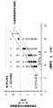
図5は、本発明の一実施形態に係る沸騰水型原子炉用燃料集合体において、可燃性毒物平均質量割合とウラン濃縮度との種々の組合せについて、炉心の成立・不成立を解析計算によって求めた結果を示すグラフの例である。ここで、可燃性毒物平均質量割合は、可燃性毒物濃度p×可燃性毒物入り燃料棒本数割合で表わされる。さらに、可燃性毒物入り燃料棒本数割合は、可燃性毒物入り燃料棒本数n/燃料集合体の燃料棒の総数Nで表わされる。したがって、可燃性毒物平均質量割合は、p・n/Nで表わされる。 FIG. 5 shows the establishment / non-establishment of the core for various combinations of the average mass ratio of combustible poisons and the enrichment of uranium in the fuel assembly for a boiling water reactor according to the embodiment of the present invention by analytical calculation. This is an example of a graph showing the results. Here, the average mass ratio of combustible poisons is expressed by the ratio of the concentration of combustible poisons p × the number of fuel rods containing combustible poisons. Further, the ratio of the number of fuel rods containing combustible poison is represented by the number of fuel rods containing combustible poison n / the total number N of fuel rods in the fuel assembly. Therefore, the average mass ratio of flammable poisons is expressed in p · n / N.
図5の核特性評価解析では、図2および図3に示す燃料集合体と同様の構成を仮定する。ここで、均質の燃料集合体が水平方向に縦横に無限に配列されていると仮定することにより、炉心の成立・否成立を判断することができる。可燃性毒物はガドリニウムであるとした。 In the nuclear characterization analysis of FIG. 5, the same configuration as the fuel assembly shown in FIGS. 2 and 3 is assumed. Here, by assuming that homogeneous fuel assemblies are arranged infinitely in the horizontal direction in the vertical and horizontal directions, it is possible to determine the establishment / non-establishment of the core. The flammable poison was gadolinium.
図5の核特性評価解析では、燃料集合体内の燃料棒配列を9×9とした。しかし、燃料集合体の核特性(中性子スペクトル)の炉心特性への影響が大きいことから、燃料集合体の水素−ウラン比が同一であれば、燃料集合体内の燃料棒の数に係りなく、実質的に図5と同様の結果となる。たとえば、10×10配列、または11×11配列であっても、実質的に図5と同様の結果となる。 In the nuclear characterization analysis of FIG. 5, the fuel rod arrangement in the fuel assembly was 9 × 9. However, since the nuclear characteristics (neutron spectrum) of the fuel assembly have a large effect on the core characteristics, if the hydrogen-uranium ratio of the fuel assembly is the same, it is substantially regardless of the number of fuel rods in the fuel assembly. The result is the same as in FIG. For example, even a 10 × 10 arrangement or an 11 × 11 arrangement gives substantially the same result as in FIG.
図2の例では、可燃性毒物入り燃料棒12の本数n=24、燃料集合体の燃料棒の総数N=74であり、図3の例では、n=36、N=74である。
In the example of FIG. 2, the number of
ウラン濃縮度をeとする。このとき、可燃性毒物平均質量割合(p・n/N)とウラン濃縮度eの種々の組合せについて、炉心が成立するか否かを解析によって求めた。その結果、図5に示すように、炉心が成立するか否かの境界条件として、2本の直線が得られた。すなわち、可燃性毒物平均質量割合(p・n/N)が、(0.57e−1.8)より大きく(0.57e−0.8)より小さい範囲が可燃性毒物添加の最適割合である。すなわち、この場合の炉心成立要件を表わす判定式(1)は、
0.57e−1.8 < p・n/N < 0.57e−0.8 ・・・(1)
で表わされる。
Let e be the enrichment of uranium. At this time, it was determined by analysis whether or not the core was established for various combinations of the average mass ratio of combustible poisons (p · n / N) and the uranium enrichment e. As a result, as shown in FIG. 5, two straight lines were obtained as a boundary condition for whether or not the core was established. That is, the range in which the average mass ratio of combustible poisons (p · n / N) is larger than (0.57e-1.8) and smaller than (0.57e-0.8) is the optimum ratio for adding combustible poisons. .. That is, the determination formula (1) expressing the core establishment requirement in this case is
0.57e-1.8 <p ・ n / N <0.57e-0.8 ・ ・ ・ (1)
It is represented by.
したがって、判定式(1)を用いて実際の燃料集合体の設計を行うことができる。 Therefore, the actual fuel assembly can be designed using the determination formula (1).
また、種々の条件の異なる燃料集合体の設計のためには、その条件に合った解析または実験により、充分な数の可燃性毒物平均質量割合(p・n/N)とウラン濃縮度eの種々の組合せについて、炉心が成立するか否かを解析によって求めることによってデータを蓄積し、その条件での図5に相当するグラフを得ることができる。そのグラフに基づいて、その条件における判定式(1)に相当する他の判定式が得られる。 In addition, for the design of fuel assemblies with different conditions, a sufficient number of combustible poison average mass ratios (p · n / N) and uranium enrichment e can be obtained by analysis or experiments suitable for the conditions. Data can be accumulated by determining whether or not the core is established for various combinations by analysis, and a graph corresponding to FIG. 5 under that condition can be obtained. Based on the graph, another determination formula corresponding to the determination formula (1) under the condition can be obtained.
判定式は、一般的には次の判定式(2)の形式が適当と思われる。
a1・e−b < p・n/N < a2・e−c ・・・(2)
ただし、a1、a2、bおよびcは正の定数であり、a1≧a2である。
In general, the following determination formula (2) is considered appropriate as the determination formula.
a1 ・ e-b <p ・ n / N <a2 ・ e-c ・ ・ ・ (2)
However, a1, a2, b and c are positive constants, and a1 ≧ a2.
上記判定式(1)、(2)は一次式であるが、一次式以外にも、2次式や他の種々の式がありうる。 The above discriminants (1) and (2) are linear expressions, but there may be a quadratic expression or various other expressions other than the linear expression.
図6は、図5の可燃性毒物平均質量割合の最適範囲内にはいる燃料集合体を沸騰水型原子炉で燃焼させた場合のサイクル燃焼度と余剰反応度との関係の解析結果の一例を示すグラフである。図7は、本発明の一実施形態に係る燃料集合体の設計において、ウラン濃縮度を上昇させた場合の集合体無限増倍率の変化を模式的に示すグラフである。図8は、本発明の一実施形態に係る燃料集合体の設計において、可燃性毒物の反応度変化に対応する可燃性毒物入り燃料棒本数の変化を模式的に示すグラフである。なお、図7および図8では、ともに、直線が示されているが、これらは模式的に示されたものであり、必ずしも直線とは限らない。 FIG. 6 shows an example of the analysis result of the relationship between the cycle burnup and the surplus reactivity when the fuel assembly within the optimum range of the average mass ratio of combustible poisons in FIG. 5 is burned in a boiling water reactor. It is a graph which shows. FIG. 7 is a graph schematically showing a change in the infinite magnification of the assembly when the uranium enrichment is increased in the design of the fuel assembly according to the embodiment of the present invention. FIG. 8 is a graph schematically showing a change in the number of fuel rods containing a combustible poison corresponding to a change in the reactivity of the combustible poison in the design of the fuel assembly according to the embodiment of the present invention. Although straight lines are shown in both FIGS. 7 and 8, these are schematically shown and are not necessarily straight lines.
ここで、図10は、現在の典型的なBWRのコントロールセル炉心における反応度価値の高い上位10本の制御棒の制御棒反応度の値を示す図である。このコントロールセルの制御棒反応度価値は、図10に示すように、最大で0.1%Δkを若干上回る程度である。コントロールセルは改良型沸騰水型軽水炉(ABWR)の場合、最大でも29個であることから、コントロールセルで制御可能な余剰反応度は最大で3%Δk以下である。 Here, FIG. 10 is a diagram showing the control rod reactivity values of the top 10 control rods having high reactivity values in the current typical BWR control cell core. As shown in FIG. 10, the control rod reactivity value of this control cell is slightly higher than 0.1% Δk at the maximum. In the case of the advanced boiling water reactor (ABWR), the maximum number of control cells is 29, so the maximum excess reactivity that can be controlled by the control cell is 3% Δk or less.
燃料集合体10の可燃性毒物平均質量割合(p・n/N)とウラン濃縮度eとの組み合わせを、判定式(1)または(2)を満たす範囲になるように設計することにより、図6に示すように、原子炉運転サイクル期間中の余剰反応度を制御棒で反応度制御可能である0〜3.0%Δkになるように設計することができる。これは、図7に示すウラン濃縮度eを(e+Δe)に変化させたときの反応度変化量(ΔS(Δe))が、図8に示す可燃性毒物入り燃料棒の集合体内の本数nと平均添加質量割合で変化する吸収材としての反応度変化量(ΔS(ΔGd))と一致することによるものである。すなわち、可燃性毒物の総量をΔGdだけ変化させることによって、ウラン濃縮度eの変化Δeを補償することができる。
The combination of the average mass ratio of combustible toxicants (p · n / N) of the
つぎに、以上説明した検討結果を利用して軽水炉用燃料集合体を設計する方法について、図9に沿って説明する。図9は、本発明の一実施形態に係る燃料集合体の設計方法の手順を示す流れ図である。 Next, a method of designing a fuel assembly for a light water reactor using the examination results described above will be described with reference to FIG. FIG. 9 is a flow chart showing a procedure of a method for designing a fuel assembly according to an embodiment of the present invention.
初めに、軽水炉用燃料集合体の構成を所定の範囲で仮定して、可燃性毒物平均質量割合(p・n/N)とウラン濃縮度eとの種々の組合せについて、炉心の成立・不成立を解析計算または実験によって求め、図5に示すように、炉心成否判定データを蓄積する(ステップS10)。 First, assuming the composition of the fuel assembly for a light water reactor within a predetermined range, the establishment / failure of the core is determined for various combinations of the average mass ratio of combustible poisons (p · n / N) and the uranium enrichment e. Obtained by analytical calculation or experiment, and as shown in FIG. 5, core success / failure determination data is accumulated (step S10).
つぎに、ステップS10で得られた炉心成否判定データに基づいて、判定式(1)や(2)のように可燃性毒物平均質量割合(p・n/N)とウラン濃縮度eとの種々の組合せに対する炉心成否判定式を決定する(ステップS11)。 Next, based on the core success / failure determination data obtained in step S10, the average mass ratio of combustible poisons (p · n / N) and the uranium enrichment e are various as in the determination formulas (1) and (2). The core success / failure determination formula for the combination of is determined (step S11).
つぎに、軽水炉用燃料集合体の可燃性毒物平均質量割合(p・n/N)とウラン濃縮度eとの組合せを具体的に仮定して(ステップS12)、その組合せについて、ステップS11で得られた炉心成否判定式に基づいて炉心成否を判定する(ステップS13)。 Next, a specific combination of the average mass ratio of combustible poisons (p · n / N) and the uranium enrichment e of the fuel assembly for a light water reactor is assumed (step S12), and the combination is obtained in step S11. The success or failure of the core is determined based on the determined success or failure of the core (step S13).
ステップS13の結果が炉心不成立(No)であった場合は、可燃性毒物平均質量割合(p・n/N)とウラン濃縮度eとの組合せを変更して、再びステップS12,S13を行う。ステップS13の結果が炉心成立(Yes)であった場合は、そのときの可燃性毒物平均質量割合(p・n/N)とウラン濃縮度eとの組合せによって、燃料集合体の設計として決定する(ステップS14)。 If the result of step S13 is that the core is not established (No), the combination of the average mass ratio of combustible poisons (p · n / N) and the uranium enrichment e is changed, and steps S12 and S13 are performed again. When the result of step S13 is the establishment of the core (Yes), the design of the fuel assembly is determined by the combination of the average mass ratio of combustible poisons (p · n / N) and the uranium enrichment e at that time. (Step S14).
以上説明した設計方法によれば、軽水炉において、ウラン濃縮度を高めたときの余剰反応度を低減することができる。また、あらかじめ炉心成否判定式を決定しておくことにより、具体的な燃料集合体の設計において、種々のパラメータを変更した場合について、炉心の成否を簡単に確認することができ、設計作業の迅速化および省力化を図ることができる。 According to the design method described above, it is possible to reduce the excess reactivity when the uranium enrichment is increased in the light water reactor. In addition, by determining the core success / failure judgment formula in advance, the success / failure of the core can be easily confirmed when various parameters are changed in the specific fuel assembly design, and the design work can be expedited. It is possible to save labor and labor.
この実施形態で、核燃料物質に添加される可燃性毒物としては、ガドリニウムを含む化合物、もしくはエルビウムを含む化合物、もしくはホウ素を含む化合物であることが好ましい。 In this embodiment, the flammable poison added to the nuclear fuel material is preferably a compound containing gadolinium, a compound containing erbium, or a compound containing boron.
さらに、核燃料物質に添加される可燃性毒物がガドリニアである場合に、その最高質量割合が20質量%未満であることが好ましい。それは、ガドリニアの最高質量割合が20質量%以上であると、ガドリニアと酸化ウランとの混合物が固溶体を生成しにくくなるからである。 Further, when the flammable poison added to the nuclear fuel material is gadlinear, the maximum mass ratio thereof is preferably less than 20% by mass. This is because when the maximum mass ratio of gadlinia is 20% by mass or more, it becomes difficult for the mixture of gadlinear and uranium oxide to form a solid solution.
ここで説明する実施形態における可燃性毒物として、奇数質量数(たとえば155または157)のガドリニウムの濃縮を行ったガドリニウムを用いるのが好ましい。これによって、ガドリニウムが持つ吸収断面積が大きくなるため、可燃性毒物の添加量を少なくする効果が得られる。 As the flammable poison in the embodiments described here, it is preferable to use gadolinium obtained by concentrating gadolinium having an odd mass number (for example, 155 or 157). As a result, the absorption cross section of gadolinium is increased, so that the effect of reducing the amount of flammable poison added can be obtained.
また、コントロールセルを含む軽水炉炉心に燃料集合体を装荷することにより、制御棒の動作による反応度変化範囲を小さく抑えられ、軽水炉炉心における燃料集合体の熱的健全性を満たしやすくする効果が得られる。 In addition, by loading the fuel assembly into the light water reactor core including the control cell, the range of reactivity change due to the operation of the control rods can be suppressed to a small size, and the effect of facilitating the thermal soundness of the fuel assembly in the light water reactor core can be obtained. Be done.
以上、本発明のいくつかの実施形態を説明したが、これらの実施形態は、例として提示したものであり、発明の範囲を限定することは意図していない。これら実施形態は、その他の様々な形態で実施されることが可能であり、発明の要旨を逸脱しない範囲で、種々の省略、置き換え、変更、組み合わせを行うことができる。これら実施形態やその変形は、発明の範囲や要旨に含まれると同様に、特許請求の範囲に記載された発明とその均等の範囲に含まれるものである。 Although some embodiments of the present invention have been described above, these embodiments are presented as examples and are not intended to limit the scope of the invention. These embodiments can be implemented in various other forms, and various omissions, replacements, changes, and combinations can be made without departing from the gist of the invention. These embodiments and modifications thereof are included in the scope and gist of the invention, as well as in the scope of the invention described in the claims and the equivalent scope thereof.
10…燃料集合体、 11,12…燃料棒、 13…チャンネルボックス、 14…ウォーターロッド、 20…被覆管、 21…核燃料物質、 30…制御棒(反応度制御装置)、 31…核計装装置(局部出力領域モニタ、LPRM) 10 ... fuel assembly, 11, 12 ... fuel rods, 13 ... channel box, 14 ... water rods, 20 ... cladding tubes, 21 ... nuclear fuel material, 30 ... control rods (reactivity control device), 31 ... nuclear instrumentation device ( Local output area monitor, LPRM)
Claims (12)
前記軽水炉用燃料集合体は複数の平行な燃料棒を有し、
前記燃料棒は長手方向に垂直な方向に互いに間隔をあけて配列され、
前記燃料棒は被覆管と前記被覆管内に封入されて少なくとも一部に濃縮ウランを含む二酸化ウランを主成分とした核燃料物質とを有し、
前記核燃料物質のうち少なくとも一部は可燃性毒物を含むものであり、
当該設計方法は、
前記燃料集合体に含まれる燃料棒の本数をN(Nは2以上の整数)、前記燃料棒のうち可燃性毒物を含む核燃料物質を封入した可燃性毒物入り燃料棒の本数をn(nは1以上かつNより小さい整数)、前記n本の可燃性毒物入り燃料棒における核燃料物質のうちの可燃性毒物の濃度(質量%)をp、前記燃料集合体の全本数にわたる平均ウラン235の濃縮度(質量%)をeとするときに、解析または実験によって、複数のp・n/Nとeのそれぞれの組合せが炉心として成立するか否かを示す炉心判定データを蓄積する炉心判定データ蓄積ステップと、
炉心判定データに基づいて、p・n/Nとeとの組合せが炉心として成立するか否かを判定する判定式を決定する炉心判定式決定ステップと、
前記判定式に基づき、仮に設定された前記燃料集合体の構成が炉心として成立するか否かを判定する炉心成否判定ステップを備え、
前記判定式は、正の定数a1、a2、bおよびc(ただし、a1≧a2)を用いて、炉心成立の条件を、
a1・e−b < p・n/N < a2・e−c
とし、
前記eは5%以上であり、
前記定数a1およびa2を0.57とし、前記定数bを1.8とし、前記定数cを0.8とするものであることを特徴とする軽水炉用燃料集合体設計方法。 It is a design method for fuel assemblies for light water reactors.
The fuel assembly for a light water reactor has a plurality of parallel fuel rods and has a plurality of parallel fuel rods.
The fuel rods are spaced apart from each other in the direction perpendicular to the longitudinal direction.
The fuel rod has a cladding tube and a nuclear fuel material containing uranium dioxide as a main component, which is enclosed in the cladding tube and contains at least a part of enriched uranium.
At least a part of the nuclear fuel material contains flammable poisons,
The design method is
The number of fuel rods contained in the fuel assembly is N (N is an integer of 2 or more), and the number of fuel rods containing flammable toxic substances containing nuclear fuel material containing flammable toxic substances is n (n is n). An integer greater than or equal to 1 and less than N), p for the concentration (mass%) of the flammable toxicants in the nuclear fuel rods in the n fuel rods containing flammable toxicants, and the concentration of average uranium-235 over the total number of fuel assemblies. Accumulation of core judgment data indicating whether or not each combination of a plurality of p · n / N and e is established as a core by analysis or experiment when the degree (mass%) is e. Steps and
Based on the core determination data, a core determination formula determination step for determining a determination formula for determining whether or not the combination of p · n / N and e is established as the core, and a core determination formula determination step.
A core success / failure determination step for determining whether or not the tentatively set configuration of the fuel assembly is established as the core based on the determination formula is provided .
The determination formula uses positive constants a1, a2, b and c (where a1 ≧ a2) to determine the conditions for establishing the core.
a1 ・ e-b <p ・ n / N <a2 ・ e-c
age,
The e is 5% or more,
The constants a1 and a2 and 0.57, the constants b and 1.8, LWR fuel assembly design method to der characterized Rukoto which 0.8 the constant c.
少なくとも1本の前記可燃性毒物入り燃料棒が、前記正方格子状の配列方向に対応する4面のうち少なくとも1面で他の燃料棒と隣接しないこと、を特徴とする請求項1または請求項2に記載の軽水炉用燃料集合体設計方法。 In the fuel assembly, the fuel rods are arranged in a square grid pattern.
1 or claim, wherein at least one fuel rod containing a flammable poison is not adjacent to another fuel rod on at least one of the four surfaces corresponding to the square grid arrangement direction. 2. The method for designing a fuel assembly for a light water reactor according to 2.
少なくとも1本の前記可燃性毒物入り燃料棒が、前記正方格子状の燃料棒配列の配列方向に対応する4面のうち少なくとも1面で他の前記可燃性毒物入り燃料棒と隣接すること、を特徴とする請求項1ないし請求項3のいずれか一項に記載の軽水炉用燃料集合体設計方法。 In the fuel assembly, the fuel rods are arranged in a square grid pattern.
At least one of the four fuel rods containing the combustible poison is adjacent to the other fuel rods containing the combustible poison on at least one of the four surfaces corresponding to the arrangement direction of the square grid fuel rod arrangement. The method for designing a fuel assembly for a light water reactor according to any one of claims 1 to 3, wherein the fuel assembly is designed.
前記軽水炉炉心は複数の燃料集合体を有し、
前記燃料集合体は長手方向に垂直な方向に互いに集合体間隙を介して隣接して正方格子状に配列され、
前記集合体間隙内には複数の反応度制御装置が配置され、
前記軽水炉用燃料集合体は複数の平行な燃料棒を有し、
前記燃料棒は長手方向に垂直な方向に互いに間隔をあけて配列され、
前記燃料棒は被覆管と前記被覆管内に封入されて少なくとも一部に濃縮ウランを含む二酸化ウランを主成分とした核燃料物質とを有し、
前記核燃料物質のうち少なくとも一部は可燃性毒物を含むものであり、
当該設計方法は、前記複数の燃料集合体のうちの少なくとも一部の前記燃料集合体について、前記燃料集合体に含まれる燃料棒の本数をN(Nは2以上の整数)、前記燃料棒のうち可燃性毒物を含む核燃料物質を封入した可燃性毒物入り燃料棒の本数をn(nは1以上かつNより小さい整数)、前記n本の可燃性毒物入り燃料棒における核燃料物質のうちの可燃性毒物の濃度(質量%)をp、前記燃料集合体の全本数にわたる平均ウラン235の濃縮度(質量%)をeとするときに、解析または実験によって、複数のp・n/Nとeのそれぞれの組合せが炉心として成立するか否かを示す炉心判定データを蓄積する炉心判定データ蓄積ステップと、
炉心判定データに基づいて、p・n/Nとeとの組合せが炉心として成立するか否かを判定する判定式を決定する炉心判定式決定ステップと、
前記判定式に基づき、仮に設定された前記燃料集合体の構成が炉心として成立するか否かを判定する炉心成否判定ステップを備え、
前記判定式は、正の定数a1、a2、bおよびc(ただし、a1≧a2)を用いて、炉心成立の条件を、
a1・e−b < p・n/N < a2・e−c
とし、
前記eは5%以上であり、
前記定数a1およびa2を0.57とし、前記定数bを1.8とし、前記定数cを0.8とするものであることを特徴とする軽水炉炉心設計方法。 It is a design method for light water reactor cores.
The light water reactor core has a plurality of fuel assemblies and has a plurality of fuel assemblies.
The fuel assemblies are arranged in a square grid so as to be adjacent to each other with an aggregate gap in the direction perpendicular to the longitudinal direction.
A plurality of reactivity control devices are arranged in the aggregate gap, and a plurality of reactivity control devices are arranged.
The fuel assembly for a light water reactor has a plurality of parallel fuel rods and has a plurality of parallel fuel rods.
The fuel rods are spaced apart from each other in the direction perpendicular to the longitudinal direction.
The fuel rod has a cladding tube and a nuclear fuel material containing uranium dioxide as a main component, which is enclosed in the cladding tube and contains at least a part of enriched uranium.
At least a part of the nuclear fuel material contains flammable poisons,
In the design method, for at least a part of the fuel assemblies, the number of fuel rods included in the fuel assemblies is N (N is an integer of 2 or more), and the fuel rods Of these, the number of fuel rods containing flammable poisons containing nuclear fuel materials containing flammable poisons is n (n is an integer greater than or equal to 1 and smaller than N), and the combustible fuel rods of the n fuel rods containing flammable poisons are combustible. When the concentration (mass%) of the toxic substance is p and the concentration (mass%) of the average uranium 235 over the total number of the fuel assemblies is e, a plurality of p · n / N and e by analysis or experiment. A core judgment data accumulation step for accumulating core judgment data indicating whether or not each combination of is established as a core, and
Based on the core determination data, a core determination formula determination step for determining a determination formula for determining whether or not the combination of p · n / N and e is established as the core, and a core determination formula determination step.
A core success / failure determination step for determining whether or not the tentatively set configuration of the fuel assembly is established as the core based on the determination formula is provided.
The determination formula uses positive constants a1, a2, b and c (where a1 ≧ a2) to determine the conditions for establishing the core.
a1 ・ e-b <p ・ n / N <a2 ・ e-c
age,
The e is 5% or more,
A light water reactor core design method, wherein the constants a1 and a2 are 0.57, the constant b is 1.8, and the constant c is 0.8.
前記可燃性毒物入り燃料棒は前記核計装装置と隣接しない位置に配置されること、を特徴とする請求項8または請求項9に記載の軽水炉炉心設計方法。 The light water reactor core further includes a nuclear instrumentation device, and the nuclear instrumentation device is arranged in the aggregate gap different from the aggregate gap in which the reactivity control device is arranged.
The light water reactor core design method according to claim 8 or 9, wherein the fuel rod containing a flammable poison is arranged at a position not adjacent to the nuclear instrumentation device.
前記炉心成否判定ステップは、前記コントロールセルを構成する前記燃料集合体で、仮に設定された前記燃料集合体の構成について、前記炉心判定式決定ステップで決定された判定式に基づいて、炉心の成否を判定すること、を特徴とする請求項8ないし請求項10のいずれか一項に記載の軽水炉炉心設計方法。 A part of the fuel assembly of the plurality of fuel assemblies constitutes a control cell adjacent to the reactivity control device and surrounding the reactivity control device.
The core success / failure determination step is the success / failure of the core based on the determination formula determined in the core determination formula determination step for the tentatively set configuration of the fuel assembly in the fuel assembly constituting the control cell. The light water core design method according to any one of claims 8 to 10, wherein the method is determined.
前記複数の燃料棒はそれぞれが、 Each of the plurality of fuel rods
長手方向に延びる被覆管と、 With a cladding tube extending in the longitudinal direction,
前記被覆管内に封入されて少なくとも一部に濃縮ウランを含む二酸化ウランを主成分とした核燃料物質と、 A nuclear fuel material containing uranium dioxide as a main component, which is encapsulated in the cladding tube and contains at least a part of enriched uranium.
を有するものであって、 And have
前記核燃料物質のうち少なくとも一部は可燃性毒物を含むものであり、 At least a part of the nuclear fuel material contains flammable poisons,
前記燃料集合体に含まれる燃料棒の本数をN(Nは2以上の整数)、前記燃料棒のうち可燃性毒物を含む核燃料物質を封入した燃料棒の本数をn(nは1以上かつNより小さい整数)、前記n本の可燃性毒物入り燃料棒における核燃料物質のうちの可燃性毒物の濃度(質量%)をp、前記燃料集合体の全本数にわたる平均ウラン235の濃縮度(質量%)をeとするときに、前記eは5%以上であり、 The number of fuel rods contained in the fuel assembly is N (N is an integer of 2 or more), and the number of fuel rods containing nuclear fuel material containing flammable toxic substances is n (n is 1 or more and N). (Small integer), p the concentration (mass%) of the flammable toxic substances in the nuclear fuel materials in the n fuel rods containing combustible poisons, and the concentration (mass%) of the average uranium-235 over the total number of the fuel assemblies. ) Is e, the e is 5% or more, and
0.57e−1.8 < p・n/N < 0.57e−0.8 0.57e-1.8 <p ・ n / N <0.57e-0.8
の関係を満たすことを特徴とする軽水炉用燃料集合体。A fuel assembly for a light water reactor characterized by satisfying the above relationship.
Priority Applications (5)
| Application Number | Priority Date | Filing Date | Title |
|---|---|---|---|
| US15/888,622 US10943703B2 (en) | 2017-02-09 | 2018-02-05 | Fuel assembly, core design method and fuel assembly design method of light-water reactor |
| KR1020180014471A KR102095810B1 (en) | 2017-02-09 | 2018-02-06 | Fuel assembly, core design method and fuel assembly design method of light-water reactor |
| RU2018104823A RU2678564C1 (en) | 2017-02-09 | 2018-02-08 | Fuel assembly, method of designing active zone and method of designing fuel assembly of light-water nuclear reactor |
| FR1851064A FR3062746B1 (en) | 2017-02-09 | 2018-02-08 | FUEL ASSEMBLY, METHOD FOR DESIGNING A CORE AND METHOD FOR DESIGNING A LIGHT WATER REACTOR |
| CN201810132914.1A CN108461161B (en) | 2017-02-09 | 2018-02-09 | Fuel assembly for light water reactor, method for designing core of light water reactor, and method for designing fuel assembly for light water reactor |
Applications Claiming Priority (2)
| Application Number | Priority Date | Filing Date | Title |
|---|---|---|---|
| JP2017022319 | 2017-02-09 | ||
| JP2017022319 | 2017-02-09 |
Publications (2)
| Publication Number | Publication Date |
|---|---|
| JP2018128445A JP2018128445A (en) | 2018-08-16 |
| JP6878251B2 true JP6878251B2 (en) | 2021-05-26 |
Family
ID=63172832
Family Applications (1)
| Application Number | Title | Priority Date | Filing Date |
|---|---|---|---|
| JP2017217136A Active JP6878251B2 (en) | 2017-02-09 | 2017-11-10 | Fuel assembly for light water reactors, core design method for light water reactors, and fuel assembly design method for light water reactors |
Country Status (4)
| Country | Link |
|---|---|
| JP (1) | JP6878251B2 (en) |
| KR (1) | KR102095810B1 (en) |
| CN (1) | CN108461161B (en) |
| RU (1) | RU2678564C1 (en) |
Families Citing this family (3)
| Publication number | Priority date | Publication date | Assignee | Title |
|---|---|---|---|---|
| CN112420223B (en) * | 2020-11-18 | 2023-02-28 | 中国核动力研究设计院 | Pressurized water reactor core long-circulation refueling loading method based on gadolinium enrichment |
| TWI816560B (en) * | 2022-09-26 | 2023-09-21 | 行政院原子能委員會核能研究所 | Design method of lattice enrichment of nuclear fuel bundle of boiling water reactor |
| CN117133490A (en) * | 2023-07-25 | 2023-11-28 | 华能核能技术研究院有限公司 | Method and system for shortening establishment process of pebble-bed high-temperature air-cooled primary-loading core |
Family Cites Families (18)
| Publication number | Priority date | Publication date | Assignee | Title |
|---|---|---|---|---|
| JPS5984184A (en) * | 1982-11-05 | 1984-05-15 | 株式会社日立製作所 | Fuel assembly for bwr type reactor |
| US4671927A (en) * | 1984-12-03 | 1987-06-09 | Westinghouse Electric Corp. | Nuclear fuel rod containing a hybrid gadolinium oxide, boron carbide burnable absorber |
| US5089210A (en) * | 1990-03-12 | 1992-02-18 | General Electric Company | Mox fuel assembly design |
| SE470485B (en) * | 1992-09-30 | 1994-05-24 | Asea Atom Ab | Reactor core for a boiler water type nuclear reactor |
| JPH0943377A (en) * | 1995-07-26 | 1997-02-14 | Toshiba Corp | Core for boiling water reactor |
| JPH0980180A (en) * | 1995-09-13 | 1997-03-28 | Hitachi Ltd | Initial loading core of reactor and operation method of reactor |
| JP3614965B2 (en) * | 1996-02-07 | 2005-01-26 | 株式会社東芝 | Nuclear reactor core |
| US6061416A (en) * | 1997-02-13 | 2000-05-09 | Hitachi, Ltd. | Fuel assembly |
| JP4088735B2 (en) * | 1999-03-29 | 2008-05-21 | 株式会社日立製作所 | Nuclear fuel assemblies and boiling water reactor cores |
| JP2004361179A (en) | 2003-06-03 | 2004-12-24 | Global Nuclear Fuel-Japan Co Ltd | Core and fuel assembly for boiling water reactor |
| CN1760990B (en) | 2004-10-15 | 2011-11-30 | 西屋电气有限责任公司 | Improved first core fuel assembly configuration and method of implementing same |
| WO2009128250A1 (en) * | 2008-04-16 | 2009-10-22 | 株式会社 東芝 | Method for production of nuclear fuel pellet, fuel assembly, method for production of the fuel assembly, and uranium powder |
| RU76744U1 (en) * | 2008-06-02 | 2008-09-27 | Открытое акционерное общество "Машиностроительный завод" | PROPELLED FUEL ASSEMBLY OF A CHANNEL NUCLEAR REACTOR WITH PROFILED FUEL |
| RU2372676C1 (en) * | 2008-06-02 | 2009-11-10 | Открытое акционерное общество "Машиностроительный завод" | Fuel assembly of pressure-tube reactor with profiled fuel |
| WO2011143172A1 (en) * | 2010-05-11 | 2011-11-17 | Thorium Power, Inc. | Fuel assembly with metal fuel alloy kernel and method of manufacturing thereof |
| JP5878442B2 (en) * | 2012-08-31 | 2016-03-08 | 日立Geニュークリア・エナジー株式会社 | Fuel assemblies and reactor cores |
| US20160217874A1 (en) * | 2013-09-27 | 2016-07-28 | Transatomic Power Corporation | Molten Salt Reactor |
| CN105390167B (en) * | 2015-11-05 | 2017-05-31 | 中国核动力研究设计院 | A kind of supercritical water reactor fuel assembly and reactor core |
-
2017
- 2017-11-10 JP JP2017217136A patent/JP6878251B2/en active Active
-
2018
- 2018-02-06 KR KR1020180014471A patent/KR102095810B1/en active IP Right Grant
- 2018-02-08 RU RU2018104823A patent/RU2678564C1/en active
- 2018-02-09 CN CN201810132914.1A patent/CN108461161B/en active Active
Also Published As
| Publication number | Publication date |
|---|---|
| JP2018128445A (en) | 2018-08-16 |
| KR102095810B1 (en) | 2020-04-02 |
| KR20180092857A (en) | 2018-08-20 |
| CN108461161B (en) | 2021-12-24 |
| RU2678564C1 (en) | 2019-01-30 |
| CN108461161A (en) | 2018-08-28 |
Similar Documents
| Publication | Publication Date | Title |
|---|---|---|
| US10943703B2 (en) | Fuel assembly, core design method and fuel assembly design method of light-water reactor | |
| JP6878251B2 (en) | Fuel assembly for light water reactors, core design method for light water reactors, and fuel assembly design method for light water reactors | |
| US20240105350A1 (en) | Light water reactor fuel assembly, light water reactor core and mox fuel assembly production method | |
| US9047994B2 (en) | Core of light water reactor and fuel assembly | |
| Şahin et al. | Utilization of nuclear waste plutonium and thorium mixed fuel in candu reactors | |
| Mahmoud et al. | Burn-up credit in criticality safety of PWR spent fuel | |
| JP2008170454A (en) | Mox fuel assembly for pressurized water reactor | |
| JP5586264B2 (en) | Fast breeder reactor core and fast breeder reactor fuel assembly | |
| JP2510565B2 (en) | Reactor fuel assembly | |
| US5610959A (en) | Hafnium doped replacement rod for nuclear fuel reconstitution | |
| JP6588155B2 (en) | Fuel assemblies and reactor cores loaded with them | |
| US20180090233A1 (en) | Light water reactor fuel assembly, light water reactor core and mox fuel assembly production method | |
| JP2008281501A (en) | Core of light-water type nuclear reactor | |
| RU2791731C1 (en) | Uranium fuel assembly for a light water reactor and method of operation of a nuclear fuel cycle | |
| Oka et al. | Light water reactor design | |
| JP7447046B2 (en) | Operation method of light water reactor uranium fuel assembly and nuclear fuel cycle | |
| JP2019178896A (en) | Fuel assembly | |
| JP2006184174A (en) | Fuel assembly of boiling water reactor | |
| JP2006064678A (en) | Fuel assembly arrangement method, fuel rod, and fuel assembly of nuclear reactor | |
| JP5090687B2 (en) | PWR nuclear fuel rod-based BWR square nuclear fuel assembly manufacturing method and nuclear fuel assembly | |
| JP2023072223A (en) | Fuel assembly and core of nuclear reactor | |
| JP2021117125A (en) | MOX fuel assembly | |
| JP2023115583A (en) | Boiling-water reactor and fuel assembly | |
| JPH07306282A (en) | Assembly for annihilation disposal of long life nuclide and core of reactor | |
| WO2017145268A1 (en) | Fuel assembly and reactor core into which same is loaded |
Legal Events
| Date | Code | Title | Description |
|---|---|---|---|
| A621 | Written request for application examination |
Free format text: JAPANESE INTERMEDIATE CODE: A621 Effective date: 20200217 |
|
| A977 | Report on retrieval |
Free format text: JAPANESE INTERMEDIATE CODE: A971007 Effective date: 20201009 |
|
| A131 | Notification of reasons for refusal |
Free format text: JAPANESE INTERMEDIATE CODE: A131 Effective date: 20201020 |
|
| A521 | Written amendment |
Free format text: JAPANESE INTERMEDIATE CODE: A523 Effective date: 20201210 |
|
| TRDD | Decision of grant or rejection written | ||
| A01 | Written decision to grant a patent or to grant a registration (utility model) |
Free format text: JAPANESE INTERMEDIATE CODE: A01 Effective date: 20210406 |
|
| A61 | First payment of annual fees (during grant procedure) |
Free format text: JAPANESE INTERMEDIATE CODE: A61 Effective date: 20210428 |
|
| R150 | Certificate of patent or registration of utility model |
Ref document number: 6878251 Country of ref document: JP Free format text: JAPANESE INTERMEDIATE CODE: R150 |