JP4088735B2 - Nuclear fuel assemblies and boiling water reactor cores - Google Patents
Nuclear fuel assemblies and boiling water reactor cores Download PDFInfo
- Publication number
- JP4088735B2 JP4088735B2 JP08655699A JP8655699A JP4088735B2 JP 4088735 B2 JP4088735 B2 JP 4088735B2 JP 08655699 A JP08655699 A JP 08655699A JP 8655699 A JP8655699 A JP 8655699A JP 4088735 B2 JP4088735 B2 JP 4088735B2
- Authority
- JP
- Japan
- Prior art keywords
- fuel
- enrichment
- gadolinia
- control rod
- rods
- Prior art date
- Legal status (The legal status is an assumption and is not a legal conclusion. Google has not performed a legal analysis and makes no representation as to the accuracy of the status listed.)
- Expired - Fee Related
Links
Images


Classifications
-
- Y—GENERAL TAGGING OF NEW TECHNOLOGICAL DEVELOPMENTS; GENERAL TAGGING OF CROSS-SECTIONAL TECHNOLOGIES SPANNING OVER SEVERAL SECTIONS OF THE IPC; TECHNICAL SUBJECTS COVERED BY FORMER USPC CROSS-REFERENCE ART COLLECTIONS [XRACs] AND DIGESTS
- Y02—TECHNOLOGIES OR APPLICATIONS FOR MITIGATION OR ADAPTATION AGAINST CLIMATE CHANGE
- Y02E—REDUCTION OF GREENHOUSE GAS [GHG] EMISSIONS, RELATED TO ENERGY GENERATION, TRANSMISSION OR DISTRIBUTION
- Y02E30/00—Energy generation of nuclear origin
- Y02E30/30—Nuclear fission reactors
Landscapes
- Monitoring And Testing Of Nuclear Reactors (AREA)
Description
【0001】
【発明の属する技術分野】
本発明は、沸騰水型原子炉(以下、BWRと略記する)の燃料集合体及び炉心に関する。
【0002】
【従来の技術】
原子力発電の経済性を一層向上させるためのひとつの方策としては、単位燃料重量当たりの取出エネルギーを高める高燃焼度化が有効である。高燃焼度化のために燃料の平均濃縮度を高くすると、熱中性子がウラン−235に吸収される割合が大きくなり、中性子吸収材に吸収される割合は小さくなるために、制御棒価値及びガドリニア反応度価値が低下する。その結果、原子炉の停止余裕が減少する。停止余裕を確保するためには、多数のガドリニア入り燃料棒を配置する必要が生じ、燃料集合体内の局所出力ピーキング係数が増大して炉心の熱的余裕が低下するという問題が生じる。
【0003】
上記の問題に対しては、特開平4-122888号公報に記載のように、(1)制御棒側に位置する燃料棒の平均濃縮度は、反制御棒側に位置する濃縮度よりも低く、かつ、(2)制御棒側に位置する燃料棒の平均可燃性毒物濃度は、反制御棒側よりも低いという燃料集合体の構成が有効である。
【0004】
運転サイクルを長期化してプラント利用率を向上させることによっても、経済性を高めることが可能である。運転サイクルの長期化に伴い、制御すべき余剰反応度は増大する。これを抑えるためにガドリニア入り燃料棒の本数を増やすと、制御棒の近傍にもガドリニア入り燃料棒を配置することになるが、これは、制御棒近傍の熱中性子束を低下させるため、制御棒価値を減少させる。さらにこの燃料集合体に隣接する制御棒を余剰反応度制御のために運転中に挿入する場合、制御棒近傍の燃料棒の出力が低く抑えられて燃焼が遅れるため、制御棒が引き抜かれたときにこの領域の燃料棒の出力が高くなる傾向がある。すなわち、ガドリニア入り燃料棒は、運転サイクルを通じて余剰反応度を制御するため、ガドリニアが過度に早く燃え尽きることのないよう、通常、熱中性子束の高い燃料集合体の最外周を避け、外周から2層目ないしこれより内側に配置される。ガドリニア入り燃料棒またはその近傍の燃料棒の出力において、制御棒履歴の影響により燃料寿命中期から末期で問題となるのは十字型制御棒側のコーナーに位置するチャンネルファスナを固定する燃料棒の座標を(1,1)とあらわした場合、(1,1)、(1,2)、(2,1)に位置する燃料棒であり、これらの燃料棒の出力に影響するのは、ガドリニア入り燃料棒を上記の燃料棒に近い(2,2)、(2,3) 、(3,2)の位置に配した場合である。
【0005】
上記の従来技術、すなわち、(1)及び(2)の構成では、制御棒側の個々の燃料棒の出力については考慮されていない。したがって、制御棒側のコーナーに位置する燃料棒の座標を(1,1)とした場合、(2,2)、(2,3) 、(3,2)の位置に可燃性毒物入り燃料棒を配置すると、これらに隣接する(1,1)、(1,2)、(2,1)の燃料棒の出力は、燃料寿命初期には隣接する可燃性毒物により抑えられ、燃料寿命中期には、隣接する制御棒が挿入されることにより抑えられ、他の燃料棒に比べ燃焼が遅れるため、制御棒を引き抜いたときに出力が高くなる。このような問題が生じるのは、燃料棒の燃料有効長の上部のみである。その一方、燃料棒の燃料有効長の下部は、サイクルの初期から中期において、炉心下部で核分裂反応が起こりやすいため、上部に比べて出力が高くなりやすい。したがって、サイクルの初期から中期においては、制御棒側の出力が反対側に比べて大きくならないようにすることが望まれる。
【0006】
【発明が解決しようとする課題】
本発明の目的は、上記に鑑み、高燃焼度化あるいは運転サイクル長期化のために平均濃縮度を高めた場合でも、燃料寿命を通じて熱的余裕を確保し、燃料の機械的健全性を維持することにより、経済性を向上できる燃料集合体及び沸騰水型原子炉の炉心を提供することにある。
【0007】
上記目的を達成するために、本発明の燃料集合体は、核分裂性物質を含む燃料を被覆管に充填した複数本の燃料棒を正方格子状に束ねた燃料棒束を角筒状のチャンネルボックスで覆ってなる燃料集合体において、チャンネルボックスと燃料棒束とを接合するチャンネルファスナを固定し正方格子の一コーナーに位置する燃料棒を基準位置として、横断面で該基準位置のコーナーとそれに対角位置のコーナーとは別の他の2つのコーナーに位置する燃料棒を結ぶ直線を境にして燃料集合体を2つの領域に分割し、チャンネルファスナ側領域とその反対側の反対側領域とすると、チャンネルファスナ側領域にある複数の燃料棒及び反対側領域にある複数の燃料棒の燃料有効長の上部の所定部分について、(1)チャンネルファスナ側領域にある複数の燃料棒の平均濃縮度は、反対側領域にある複数の燃料棒の平均濃縮度よりも低く、(2)チャンネルファスナ側領域にある燃料棒の平均可燃性毒物濃度は反対側領域にある燃料棒の平均可燃性毒物濃度よりも低く、かつ(3)チャンネルファスナを固定する燃料棒の座標を(1,1)としたとき、 (2,2)、(2,3)、(3,2)の座標に位置する燃料棒は可燃性毒物を添加しない燃料棒とし、上記座標以外に位置する燃料棒のうち少なくとも1本以上を可燃性毒物を添加した燃料棒とするとともに、チャンネルファスナ側領域にある複数の燃料棒及び反対側領域にある複数の燃料棒の燃料有効長の下部の所定の領域については、チャンネルファスナ側領域にある複数の燃料棒の平均濃縮度は、反対側領域にある複数の燃料棒の平均濃縮度と等しくしたことを特徴とする。
【0008】
本発明は、チャンネルファスナ側領域にある複数の燃料棒及び反対側領域にある複数の燃料棒の燃料有効長の上部の所定部分については、(1)、(2)及び(3)の構成を組み合わせることで、それぞれの構成を単独で実施した場合には得られない作用効果が得られることに着目したものである。次にこの燃料集合体の作用について説明する。ところで燃料集合体は4体を組としてそれらの中心に十字型制御棒が配置された制御セルとして原子炉に装荷される。本発明の燃料集合体においてチャンネルボックスと燃料棒束とを接合するチャンネルファスナを固定し正方格子の一コーナーに位置する燃料棒の基準位置は、十字型制御棒で十字に交差する角にあたるので、説明の都合上、上記の「チャンネルファスナ側領域」及び「反対側領域」を、それぞれ「制御棒側領域」及び「反制御棒側領域」と、ときに言い換える。
【0009】
本発明の構成によれば、制御棒領域にある複数の燃料棒及び反制御棒領域にある複数の燃料棒の燃料有効長の上部の所定部分については、燃料寿命初期から中期では、制御棒側領域の無限増倍率が反制御棒側領域のそれよりも高くなるため、制御棒側領域の燃料棒の燃焼が促進される。特に、燃料寿命中期から末期で熱的に問題となる制御棒側のコーナー(1,1)を基準とする(2,2)、(2,3) 、(3,2)の燃料格子に位置する燃料棒の燃焼が初期から中期の間に進む。燃料寿命中期から末期では、反制御棒側領域の無限増倍率が制御棒側領域のそれよりも高くなるため、燃焼の進みかたの違いとあいまって、制御棒側領域の燃料棒の出力は低く抑えられる。したがって、燃料寿命中期から末期において隣接する制御棒が運転中に挿入される場合でも、既に制御棒側の燃料棒の燃焼は進んでいるため、制御棒が引き抜かれたときにも制御棒近傍の燃料棒の出力が過大となることはない。
【0010】
以上説明したように、本発明によれば、制御棒領域にある複数の燃料棒及び反制御棒領域にある複数の燃料棒の燃料有効長の上部の所定部分については、燃料棒出力に及ぼす制御棒履歴の影響を低減して燃料寿命を通じて熱的余裕を確保できるため、燃料の平均濃縮度を増加させて高燃焼度化または運転長期化を図ることにより、BWRの経済性を向上させることができる。また熱的余裕の故に、燃料ペレットの溶融や燃料被覆管の塑性歪等の損傷がない燃料の機械的健全性を維持することができる。
【0011】
これに加えて、本発明の燃料集合体は、上述のように、制御棒側領域の燃料棒および反制御棒側領域の燃料棒の燃料有効長の下部の所定の領域については、制御棒側領域にある複数の燃料棒の平均濃縮度は、反制御棒側領域のそれと等しくしている。
【0012】
上記のように燃料集合体の上部に対して(1)〜(3)を適用し、下部で両領域での平均濃縮度を等しくしたのは、次の理由による。BWR炉心では、冷却水が炉心下部から流入し、炉心を冷却することにより沸騰水(二相流)となって上部から流出していくため、炉心下部では炉心上部に比べ減速材(水)密度が大きくなる。サイクル初期から中期では、上記により炉心下部で核分裂反応が起こりやすいため、出力も下部の方が高くなりやすい。一方、サイクル末期では、炉心上部でウラン−235が燃え残っており、また減速材密度が低く中性子エネルギーが比較的高いためウラン-238からプルトニウム-239への転換が促進されることから、炉心上部の出力が高くなりやすい。高燃焼度化、または運転長期化した炉心に装荷する燃料集合体では、ウラン濃縮度が高いことからガドリニア入り燃料棒を多数く配置するため、サイクル末期の制御棒引き抜き時に生じる炉心上部の出力ピークが大きくなる傾向がある。そこで本発明では、サイクル初期から中期における特に炉心上部の制御棒側の出力が過度に低くならないようにすることにより均等に燃焼を進めて制御棒側のウラン-235が燃え残らないようにし、サイクル末期の炉心上部の制御棒側の出力が過度に高くならないようにするとともに、サイクルの初期から中期における、炉心下部の制御棒側の出力が反対側に比べて大きくならないようにしている。
【0013】
また、上記目的を達成するために、本発明の沸騰水型原子炉の炉心は、中性子吸収材を含む十字型制御棒を中心に4体の燃料集合体が隣接してなる複数の制御棒セルを配列して備えた炉心において、上記本発明の燃料集合体を複数体含むものである。
【0014】
そしてこの沸騰水型原子炉の炉心において、十字型制御棒が挿入される、制御棒セル内で隣り合う燃料集合体の間隙を、制御棒がなく制御棒セル間で隣り合う燃料集合体の間隙より大きくするとよい。またこの沸騰水型原子炉の炉心は、1サイクルの運転を終了したときに燃焼の進んだ燃料集合体を未照射の燃料集合体で置き換える割合を全燃料集合体数の2/7以上とするとともに、運転中に炉心に挿入する十字型制御棒の周囲に炉内滞在2サイクル目または3サイクル目の燃料集合体を少なくとも1つ配置することが好ましい。
【0015】
【発明の実施の形態】
以下、本発明の実施の形態を図面を用いて説明する。本発明の実施の形態では、いずれも、燃料として濃縮ウランの二酸化物(UO2)を、可燃性毒物としてはガドリニア(Gd2O3)を使用しているが、プルトニウムを富化したウランの二酸化物(MOX)や回収ウランの二酸化物等のその他の燃料物質や、ホウ素やユーロピウムの化合物等、その他の可燃性毒物を使用することもできる。
【0016】
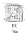
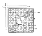
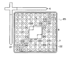
図1は、本発明の第1実施の形態のBWR用燃料集合体の横断面図を示したものである。燃料集合体は、燃料棒10が9×9の正方格子状に配置されており、その中央部には、中性子の減速が燃料集合体内で均等に行われるように水が流れる太径のウォータロッド5が2本配置されている。ここで、2本のウォータロッド5は、7本の燃料棒を配置可能な領域に設置されている。燃料集合体4体に1本の割合で十字形の制御棒6(一部のみ図示)が装荷される。制御棒6の制御材としては炭化ホウ素またはハフニウムが使用される。
【0017】
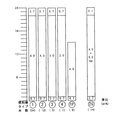
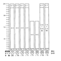
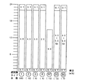
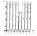
燃料集合体8はウラン濃縮度及びガドリニア濃度の異なる6種類の燃料棒からなる。図2に、本実施の形態の燃料集合体の軸方向における濃縮度及びガドリニア濃度の分布を示す。
【0018】
高濃縮度燃料棒1は、燃料有効長を軸方向に24ノードに分けた場合、上端の2/24及び下端の1/24に天然ウランを配置し、その間の21/24は濃縮度4.9wt%でガドリニアを含まない。その他の燃料棒については濃縮ウラン部のみについて説明する。中濃縮度燃料棒2は濃縮ウラン部の濃縮度は4.0wt%でガドリニアを含まない。低濃縮度燃料棒3は濃縮ウラン部の濃縮度は3.0wt%でガドリニアを含まない。
【0019】
高濃縮度部分長燃料棒1Pは、他の燃料棒に比べ有効長が15/24と短く、濃縮度は4.9wt%でガドリニアを含まない。中濃縮度部分長燃料棒2Pは、やはり他の燃料棒に比べ有効長が約2/3と短く、濃縮度は4.0wt%でガドリニアを含まない。
【0020】
ガドリニア入り燃料棒2Gはウラン濃縮度は4.0wt%でガドリニア濃度を5.0wt%としている。
【0021】
本実施の形態では、燃料集合体全体の平均濃縮度は約4.0wt%、ガドリニア平均濃度は約1.0wt%である。ここで、燃料棒を制御棒側領域21と制御棒と反対側の領域(反制御棒側領域)22に分けて両者を比較する。制御棒側領域21に配置される34本の燃料棒10の平均濃縮度は約3.9wt%であり、平均ガドリニア濃度は約0.9wt%である。これに対して、反制御棒側領域22に位置する燃料棒34本の燃料棒1〜3の平均濃縮度は約4.1wt%、平均ガドリニア濃度は約1.2wt%と、いずれも制御棒側領域21よりも高く設定されている。
【0022】
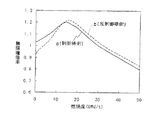
本実施の形態によれば、無限増倍率は、図3に示すように燃料寿命初期から中期(0〜20GWd/t)では制御棒側領域21で反制御棒側領域22よりも大きくなる。燃料寿命中期から末期(20〜45GWd/t)では逆に反制御棒側で制御棒側よりも無限増倍率が大きくなる。このような作用により、燃料寿命中期から末期で隣接する制御棒を運転中に挿入する場合、この制御棒を引き抜いたときの出力上昇が過大になることはない。したがって、炉心の熱的余裕を確保でき、高燃焼度化や運転サイクル長期化が可能となる。また、最大線出力密度(燃料棒単位長さ当りの最大値)が過大にならず熱的余裕があるため、燃料ペレットの溶融や燃料被覆管の塑性歪の起きない、燃料の機械的健全性を維持することができる。
【0023】
なお、燃料集合体8の最外層に配置される燃料棒は、通常どおり、ガドリニアの含まない燃料棒である。ガドリニア入り燃料棒は、1サイクルの余剰反応度を制御するために用いられ、サイクル末期にちょうどガドリニアが燃え尽きるようにその本数や濃度、装荷位置が設計される。したがって水ギャップに隣接して最も熱中性子が多くなる燃料集合体の最外層を避け、熱中性子が適切な密度で分布する燃料集合体の外周から2層目またはそれより内側にガドリニア入り燃料棒を装荷する。
【0024】
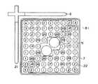
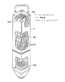
本発明の燃料集合体は、従来の燃料集合体と同様、図19の一部切欠斜視図に示すように、上部タイプレート14a,下部タイプレート14d,チャンネルファスナ14b,スペーサ14c,ウォータロッド5(図示せず),燃料棒10,チャンネルボックス7などから構成される。このうち上部タイプレート14aの1つのコーナー部に取り付けられたチャンネルファスナ14bは、制御棒を中心として4体の燃料集合体を互いに固定するためのものであるから、燃料集合体単体でみた場合、上記制御棒側領域21はチャンネルファスナ14bが位置する側の領域(チャンネルファスナ領域)に相当する。また反制御棒側領域22はチャンネルファスナ領域の反対側の反対領域に相当する。
【0025】
次に、本発明をBWRの炉心に適用した実施の形態について説明する。図4は本発明の第2実施の形態のBWR炉心の燃料装荷パターンを示す(炉心1/4横断面図)。図4の燃料集合体中の数字は当該燃料集合体の炉内滞在サイクル数を示す。
【0026】
電気出力は1100MW、熱出力は3293MW、燃料集合体数は764体、運転サイクル長さは19ヵ月、平均取出燃焼度を約45GWd/tである。このような運転条件の炉心では、1サイクル当たりの取替体数が全燃料集合体数の2/7を超え、約1/3を一度に取り替えることになる。
【0027】
炉心からの中性子漏洩を減らして所要ウラン濃縮度を低減するため、最外周には燃焼の進んだ炉内滞在3、4サイクル目燃料を装荷する。制御棒履歴の影響を抑えるために残りの3サイクル目燃料を制御棒セル(太線で図示する、隣接する燃料集合体4体をいう)11に装荷すると、制御棒セル11以外のセルは1サイクル目燃料と2サイクル目燃料のみで構成する必要がある。このように比較的燃焼の進んでいない燃料から構成されるセルが多くなると停止余裕が減少する傾向がある。
【0028】
本実施の形態では、運転中に制御棒を挿入する制御棒セル11は、炉内滞在2サイクル目または3サイクル目の燃料集合体から構成される。このような構成によれば、制御棒を引き抜いたときの出力上昇が過大になることはなく、炉心の熱的余裕を確保できる。また、制御棒セル11以外に比較的燃焼が進んだ3サイクル目燃料を散在させることにより停止余裕を確保できる。したがって、運転サイクル長期化が可能となる。
【0029】
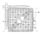
図5は、本発明の第3実施の形態のBWR用燃料集合体の横断面図を示したものである。図6に本実施の形態の燃料集合体の軸方向における濃縮度及びガドリニア濃度の分布を示す。燃料集合体は、図1に示した第1実施の形態と同様に燃料棒10が9×9の正方格子状に配置されている。
【0030】
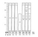
高濃縮度燃料棒1は、燃料有効長を軸方向に24ノードに分けた場合、上端の2/24及び下端の1/24に天然ウランを配置し、その間の21/24は濃縮度4.9wt%でガドリニアを含まない。その他の燃料棒については濃縮ウラン部のみについて説明する。中濃縮度燃料棒2は濃縮ウラン部の濃縮度は4.0wt%でガドリニアを含まない。低濃縮度燃料棒3は濃縮ウラン部の濃縮度は3.0wt%でガドリニアを含まない。超低濃縮度燃料棒4は濃縮ウラン部の濃縮度は2.0wt%でガドリニアを含まない。
【0031】
高濃縮度部分長燃料棒1Pは、他の燃料棒に比べ有効長が15/24と短く濃縮度は4.9wt%でガドリニアを含まない。
【0032】
ガドリニア入り燃料棒2Gはウラン濃縮度は4.0wt%でガドリニア濃度を5.0wt%としている。
【0033】
本実施の形態では、燃料集合体全体の平均濃縮度は約4.0wt%、ガドリニア平均濃度は約1.0wt%である。制御棒側領域21に配置される34本の燃料棒1〜3の平均濃縮度は約3.9wt%であり、平均ガドリニア濃度は約0.9wt%である。これに対して、反制御棒側領域22に位置する燃料棒34本の燃料棒1〜3の平均濃縮度は約4.1wt%、平均ガドリニア濃度は約1.2wt%と、いずれも制御棒側領域21よりも高く設定されていることは第1実施の形態と同じである。
【0034】
第1の実施の形態と異なるのは、最外周の燃料棒の濃縮度を制御棒側領域21で反制御棒側領域22べて低くしたことである。本実施の形態によれば、図1に示す第1実施の形態とほぼ同様な作用が得られ、炉心の熱的余裕を増大でき、高燃焼度化や運転サイクル長期化が可能となる。
【0035】
図7は、本発明の第4実施の形態のBWR用燃料集合体の横断面図を示すものである。図8に、本実施の形態の燃料集合体の軸方向における濃縮度及びガドリニア濃度の分布を示す。燃料集合体は、図1に示した第1実施の形態と同様に燃料棒10が9×9の正方格子状に配置されている。
【0036】
高濃縮度燃料棒1は、燃料有効長を軸方向に24ノードに分けた場合、上端の2/24及び下端の1/24に天然ウランを配置し、その間の21/24は濃縮度4.9wt%でガドリニアを含まない。その他の燃料棒については濃縮ウラン部のみについて説明する。中濃縮度燃料棒2は濃縮ウラン部の濃縮度は4.0wt%でガドリニアを含まない。低濃縮度燃料棒3は濃縮ウラン部の濃縮度は3.0wt%でガドリニアを含まない。
【0037】
高濃縮度部分長燃料棒1Pは、他の燃料棒に比べ有効長が15/24と短く濃縮度は4.9wt%でガドリニアを含まない。
【0038】
ガドリニア入り燃料棒2Gはウラン濃縮度は4.0wt%でガドリニア濃度を5.0wt%としている。ガドリニア入り低濃縮度燃料棒3Gはウラン濃縮度は3.0wt%でガドリニア濃度を5.0wt%としている。
【0039】
本実施の形態では、燃料集合体全体の平均濃縮度は約4.0wt%、ガドリニア平均濃度は約1.0wt%である。
【0040】
制御棒側領域21に配置される34本の燃料棒1〜3の平均濃縮度は約3.9wt%であり、平均ガドリニア濃度は約0.9wt%である。これに対して、反制御棒側領域22に位置する燃料棒34本の燃料棒1〜3の平均濃縮度は約4.1wt%、平均ガドリニア濃度は約1.2wt%と、いずれも制御棒側領域21よりも高く設定されていることは第1実施の形態と同じである。
【0041】
第1の実施の形態と異なるのは、制御棒側領域21に配置するガドリニア入り燃料棒のウラン濃縮度を反制御棒側領域22に比べて低くしたことである。本実施の形態によれば、図1に示す第1実施の形態とほぼ同様な作用が得られ、炉心の熱的余裕を確保でき、高燃焼度化や運転サイクル長期化が可能となる。
【0042】
図9は、本発明の第5実施の形態のBWR用燃料集合体の横断面図を示したものであり、制御棒側の水ギャップが反対側よりも広いいわゆるD格子タイプのBWRに適用した例である。D格子タイプは、十字型制御棒6を中心に4体の燃料集合体83が配置された制御棒セル内で隣り合う燃料集合体同士の間隙で制御棒が挿入される間隙g1を、制御棒セル間で隣り合う燃料集合体同士の間隙で制御棒が挿入されない間隙g2より大きくしたものである。このように制御棒が挿入される側の水ギャップ幅が反対側に比べて広いD格子プラントでは、制御棒を引き抜いたときの減速材分布が横断面における制御棒側に偏在したものになる。したがって本発明の作用は水ギャップ幅が両側で等しいC格子プラントと同じであるが、発明の効果はより大きくなる。
【0043】
図10に、本実施の形態の燃料集合体の軸方向における濃縮度及びガドリニア濃度の分布を示す。燃料集合体は、図1に示した第1実施の形態と同様に燃料棒10が9×9の正方格子状に配置されている。
【0044】
高濃縮度燃料棒1は、燃料有効長を軸方向に24ノードに分けた場合、上端の2/24及び下端の1/24に天然ウランを配置し、その間の21/24は濃縮度4.9wt%でガドリニアを含まない。その他の燃料棒については濃縮ウラン部のみについて説明する。中濃縮度燃料棒2は濃縮ウラン部の濃縮度は4.0wt%でガドリニアを含まない。低濃縮度燃料棒3は濃縮ウラン部の濃縮度は3.0wt%でガドリニアを含まない。超低濃縮度燃料棒4は濃縮ウラン部の濃縮度は2.0wt%でガドリニアを含まない。
【0045】
高濃縮度部分長燃料棒1Pは、他の燃料棒に比べ有効長が15/24と短く濃縮度は4.9wt%でガドリニアを含まない。中濃縮度部分長燃料棒2Pは、他の燃料棒に比べ有効長が15/24と短く濃縮度は4.9wt%でガドリニアを含まない。
【0046】
ガドリニア入り燃料棒2Gはウラン濃縮度は4.0wt%でガドリニア濃度を5.0wt%としている。ガドリニア入り低濃縮度燃料棒3Gはウラン濃縮度は3.0wt%でガドリニア濃度を5.0wt%としている。
【0047】
本実施の形態では、燃料集合体全体の平均濃縮度は約3.9wt%、ガドリニア平均濃度は約1.0wt%である。制御棒側領域21に配置される34本の燃料棒1〜3の平均濃縮度は約3.8wt%であり、平均ガドリニア濃度は約0.9wt%である。一方、反制御棒側領域22に位置する燃料棒34本の燃料棒1〜3の平均濃縮度は約4.0wt%、平均ガドリニア濃度は約1.2wt%と、いずれも制御棒側領域21よりも高く設定されていることは第1実施の形態と同じである。
【0048】
第1の実施の形態と異なるのは、最外周の燃料棒の濃縮度及びガドリニア入り燃料棒の濃縮度を反対側に比べて低くしたことである。本実施の形態によれば、D格子プラントについて炉心の熱的余裕を確保でき、高燃焼度化や運転サイクル長期化が可能となる。
【0049】
図11は、本発明の第6実施の形態のBWR用燃料集合体の横断面図を示したものである。図12に、本実施の形態の燃料集合体の軸方向における濃縮度及びガドリニア濃度の分布を示す。
【0050】
高濃縮度燃料棒1は、燃料有効長を軸方向に24ノードに分けた場合、上端の2/24及び下端の1/24に天然ウランを配置し、その間の21/24は濃縮度4.9wt%でガドリニアを含まない。その他の燃料棒については濃縮ウラン部のみについて説明する。中濃縮度燃料棒2は濃縮ウラン部の濃縮度は4.0wt%でガドリニアを含まない。低濃縮度燃料棒3は濃縮ウラン部の濃縮度は3.0wt%でガドリニアを含まない。
【0051】
高濃縮度部分長燃料棒1Pは、他の燃料棒に比べ有効長が15/24と短く濃縮度は4.9wt%でガドリニアを含まない。
【0052】
ガドリニア入り燃料棒2Gはウラン濃縮度は4.0wt%でガドリニア濃度を5.0wt%としている。ガドリニア入り上部低濃縮度燃料棒5Gは、ガドリニア濃度を5.0wt%とし、燃料有効長の15/24より下部ではウラン濃縮度は4.0wt%、15/24よりも上部ではウラン濃縮度は3.0wt%としている。
【0053】
下部ガドリニア入り上部低濃縮度燃料棒6Gは、燃料有効長の15/24より下部ではウラン濃縮度は4.0wt%でガドリニア濃度を5.0wt%、15/24よりも上部ではウラン濃縮度は3.0wt%でガドリニアを含まない。
【0054】
本実施の形態では、燃料有効長の15/24より下部では制御棒側と反対側の平均濃縮度及び平均ガドリニア濃度を同一とし、15/24よりも上部の平均濃縮度及びガドリニア濃度を制御棒側領域21で反制御棒側領域22よりも低くしたことが特徴である。
【0055】
本実施の形態は、燃料寿命末期で燃料棒出力に及ぼす制御棒履歴の影響が問題となるのは燃料有効長の上部のみであることに着目したものである。上記の構成によれば、燃料寿命末期の熱的余裕は第1実施の形態と同様に増大でき、さらに、燃料寿命初期で制御棒側の出力が反対側に比べて大きくならないように工夫したものである。
【0056】
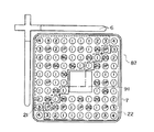
図13は、本発明の第7実施の形態のBWR用燃料集合体の横断面図を示したものである。燃料集合体は、燃料棒が9×9の正方格子状に配置されておりその中央部に水が流れる断面がほぼ正方形のウォータチャンネル9が1本配置されている。ウォータチャンネル9は、9本の燃料棒を配置可能な領域に設置されている。燃料集合体85はウラン濃縮度又はガドリニア濃度の異なる5種類の燃料棒からなる。
【0057】
高濃縮度燃料棒1は、燃料有効長を軸方向に24ノードに分けた場合、上端の2/24及び下端の1/24に天然ウランを配置し、その間の21/24は濃縮度4.9wt%でガドリニアを含まない。その他の燃料棒については濃縮ウラン部のみについて説明する。中濃縮度燃料棒2は濃縮ウラン部の濃縮度は4.0wt%でガドリニアを含まない。低濃縮度燃料棒3は濃縮ウラン部の濃縮度は3.0wt%でガドリニアを含まない。
【0058】
ガドリニア入り燃料棒2Gはウラン濃縮度は4.0wt%でガドリニア濃度を5.0wt%としている。ガドリニア入り低濃縮度燃料棒3Gはウラン濃縮度は3.0wt%でガドリニア濃度を5.0wt%としている。図14に、本実施の形態の燃料集合体の軸方向における濃縮度及びガドリニア濃度の分布を示す。
【0059】
本実施の形態では、制御棒側領域21に位置する燃料棒1〜3の平均濃縮度及び平均ガドリニア濃度がいずれも制御棒側領域21よりも高く設定されていることは図7に示した第4実施の形態と同じであり、同様に炉心の熱的余裕を確保でき、高燃焼度化や運転サイクル長期化が可能となる。
【0060】
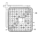
図15は、本発明の第8実施の形態のBWR用燃料集合体の横断面図を示したものである。燃料集合体は、燃料棒が10×10の正方格子状に配置されておりそのほぼ中央部に水が流れる断面がほぼ正方形のウォータチャンネル91が1本配置されている。ウォータチャンネル91は、9本の燃料棒を配置可能な領域に設置されている。燃料集合体86はウラン濃縮度及びガドリニア濃度の異なる5種類の燃料棒からなる。
【0061】
高濃縮度燃料棒1は、燃料有効長を軸方向に24ノードに分けた場合、上端の2/24及び下端の1/24に天然ウランを配置し、その間の21/24は濃縮度4.9wt%でガドリニアを含まない。その他の燃料棒については濃縮ウラン部のみについて説明する。中濃縮度燃料棒2は濃縮ウラン部の濃縮度は4.0wt%でガドリニアを含まない。低濃縮度燃料棒3は濃縮ウラン部の濃縮度は3.0wt%でガドリニアを含まない。超低濃縮度燃料棒4は濃縮ウラン部の濃縮度は2.0wt%でガドリニアを含まない。
【0062】
高濃縮度部分長燃料棒1Pは、他の燃料棒に比べ有効長が15/24と短く濃縮度は4.9wt%でガドリニアを含まない。
【0063】
ガドリニア入り燃料棒2Gはウラン濃縮度は4.0wt%でガドリニア濃度を5.0wt%としている。ガドリニア入り低濃縮度燃料棒3Gはウラン濃縮度は3.0wt%でガドリニア濃度を5.0wt%としている。図16に、本実施の形態の燃料集合体の軸方向における濃縮度及びガドリニア濃度の分布を示す。
【0064】
本実施の形態では、ガドリニア入り燃料棒の平均濃縮度を制御棒側領域21で反制御棒側領域22に比べ低くしている。本実施の形態によれば、図7に示す第4実施の形態とほぼ同様な作用が得られ、炉心の熱的余裕を確保でき、高燃焼度化や運転サイクル長期化が可能となる。
【0065】
図17は、本発明の第9実施の形態のBWR用燃料集合体の横断面図を示したものである。図18に、本実施の形態の燃料集合体の軸方向における濃縮度及びガドリニア濃度の分布を示す。
【0066】
高濃縮度燃料棒1は、燃料有効長を軸方向に24ノードに分けた場合、上端の2/24及び下端の1/24に天然ウランを配置し、その間の21/24は濃縮度4.9wt%でガドリニアを含まない。その他の燃料棒については濃縮ウラン部のみについて説明する。中濃縮度燃料棒2は濃縮ウラン部の濃縮度は4.0wt%でガドリニアを含まない。低濃縮度燃料棒3は濃縮ウラン部の濃縮度は3.0wt%でガドリニアを含まない。
【0067】
高濃縮度部分長燃料棒1Pは、他の燃料棒に比べ有効長が15/24と短く濃縮度は4.9wt%でガドリニアを含まない。
【0068】
ガドリニア入り燃料棒2Gはウラン濃縮度は4.0wt%でガドリニア濃度を5.0wt%としている。
【0069】
ガドリニア入り上部低濃縮度燃料棒5Gは、ガドリニア濃度を5.0wt%とし、燃料有効長の15/24より下部ではウラン濃縮度は4.0wt%、15/24よりも上部ではウラン濃縮度は3.0wt%としている。下部ガドリニア入り上部低濃縮度燃料棒6Gは、燃料有効長の15/24より下部ではウラン濃縮度は4.0wt%でガドリニア濃度を5.0wt%、15/24よりも上部ではウラン濃縮度は3.0wt%でガドリニアを含まない。
【0070】
本実施の形態では、燃料有効長の15/24より下部では制御棒側と反対側の平均濃縮度及び平均ガドリニア濃度を同一とし、15/24よりも上部の平均濃縮度及びガドリニア濃度を制御棒側で反対側よりも低くしたことが特徴である。
【0071】
上記の構成によれば、図11に示した第6実施の形態とほぼ同様な作用が得られ、燃料寿命を通じて炉心の熱的余裕を増大できる。
【0072】
以上の実施の形態では、上端部、下端部の天然ウラン領域の長さをそれぞれ燃料有効長の2/24、1/24としたが、熱的余裕をさらに増大させるために、それぞれ1/24、1/24、または1/24、0/24などの組み合わせにすることも可能である。この場合は平均ウラン濃縮度を若干増加させる必要が生じる。
【0073】
【発明の効果】
本発明によれば、燃料集合体は、チャネルファスナ側領域(言い換えれば制御棒側領域)にある複数の燃料棒の平均濃縮度及び平均ガドリニア濃度を、反対側領域(言い換えれば反制御棒側領域)のそれらよりも低く、かつ制御棒のコーナーに近い燃料棒位置(2,2)、(2,3)、(3,2)にはガドリニア入り燃料棒を配置しない構成としたので、無限増倍率は、燃料寿命初期から中期では制御棒側領域で反制御棒側領域よりも大きく、燃料寿命中期から末期では逆に反制御棒側領域で制御棒側領域よりも無限増倍率が大きくなり、したがって制御棒側領域の燃料棒は燃料寿命初期から中期にかけて燃焼が進むため、燃料寿命中期から末期で隣接する制御棒を運転中に挿入する場合、この制御棒を引き抜いたときの出力上昇が過大にならず、燃料寿命を通じて熱的余裕を確保でき、高燃焼度化または運転サイクル長期化が可能となり、BWRの経済性を一層向上できる。また熱的余裕の故に燃料棒に溶融や過度の歪が生じねることなく、燃料の機械的健全性を確保できる。
【図面の簡単な説明】
【図1】本発明の第1実施の形態を示す燃料集合体の横断面図。
【図2】図1の燃料集合体の軸方向における濃縮度及びガドリニアの分布を示す図。
【図3】図1の燃料集合体の無限増倍率の燃焼度依存性を示す図。
【図4】本発明の第2実施の形態を示す炉心の燃料装荷パターンの横断面図。
【図5】本発明の第3実施の形態を示す燃料集合体の横断面図。
【図6】図5の燃料集合体の軸方向における濃縮度及びガドリニアの分布を示す図。
【図7】本発明の第4実施の形態を示す燃料集合体の横断面図。
【図8】図7の燃料集合体の軸方向における濃縮度及びガドリニアの分布を示す図。
【図9】本発明の第5実施の形態を示す燃料集合体の横断面図。
【図10】図9の燃料集合体の軸方向における濃縮度及びガドリニアの分布を示す図。
【図11】本発明の第6実施の形態を示す燃料集合体の横断面図。
【図12】図11の燃料集合体の軸方向における濃縮度及びガドリニアの分布を示す図。
【図13】本発明の第7実施の形態を示す燃料集合体の横断面図。
【図14】図13の燃料集合体の軸方向における濃縮度及びガドリニアの分布を示す図。
【図15】本発明の第8実施の形態を示す燃料集合体の横断面図。
【図16】図15の燃料集合体の軸方向における濃縮度及びガドリニアの分布を示す図。
【図17】本発明の第9実施の形態を示す燃料集合体の横断面図。
【図18】図17の燃料集合体の軸方向における濃縮度及びガドリニアの分布を示す図。
【図19】本発明による燃料集合体の一部切欠斜視図。
【符号の説明】
1,2,3,4…燃料棒
1P,2P…部分長燃料棒
2G,3G,5G,6G…ガドリニア入り燃料棒
4…ウォータロッド
6…制御棒
7…チャンネルボックス
8…燃料集合体
9…ウォータチャンネル
10…燃料棒
11…制御棒セル
14a…上部タイプレート
14b…チャンネルファスナ
14c…スペーサ
14d…下部タイプレート
21…制御棒側領域
22…反制御棒側領域
81,82,83,84,85,86,…燃料集合体
91…ウォータチャンネル[0001]
BACKGROUND OF THE INVENTION
The present invention relates to a fuel assembly and a core of a boiling water reactor (hereinafter abbreviated as BWR).
[0002]
[Prior art]
As one measure for further improving the economic efficiency of nuclear power generation, it is effective to increase the burnup to increase the extracted energy per unit fuel weight. When the average enrichment of the fuel is increased for higher burnup, the rate of thermal neutrons absorbed by uranium-235 increases and the rate of absorption by neutron absorbers decreases, so the control rod value and gadolinia Reactivity value is reduced. As a result, the reactor shutdown margin is reduced. In order to secure the stop margin, it is necessary to arrange a large number of gadolinia-containing fuel rods, which causes a problem that the local power peaking coefficient in the fuel assembly increases and the thermal margin of the core decreases.
[0003]
To solve the above problem, as described in Japanese Patent Laid-Open No. 4-122888, (1) the average enrichment of the fuel rod located on the control rod side is lower than the enrichment located on the non-control rod side. (2) The fuel assembly configuration in which the average flammable poison concentration of the fuel rod located on the control rod side is lower than that on the non-control rod side is effective.
[0004]
Economic efficiency can also be improved by extending the operation cycle and improving the plant utilization rate. As the operating cycle becomes longer, the excess reactivity to be controlled increases. If the number of fuel rods containing gadolinia is increased in order to suppress this, fuel rods containing gadolinia are also placed near the control rods. This reduces the thermal neutron flux in the vicinity of the control rods. Decrease value. In addition, when a control rod adjacent to this fuel assembly is inserted during operation to control excess reactivity, the output of the fuel rod in the vicinity of the control rod is kept low and combustion is delayed, so when the control rod is pulled out However, the output of the fuel rods in this region tends to increase. That is, since the fuel rods with gadolinia control the excess reactivity throughout the operation cycle, usually avoid the outermost circumference of the fuel assembly having a high thermal neutron flux and avoid two layers from the outer circumference so that the gadolinia does not burn out too quickly. It is arranged inside the eyes or inside. In the output of the fuel rod with gadolinia or its vicinity, the problem of the control rod history is the problem of the fuel rod coordinates that fix the channel fastener located at the corner on the cross-shaped control rod side. Is expressed as (1,1), the fuel rods located at (1,1), (1,2), (2,1), and the output of these fuel rods is affected by gadolinia This is a case where the fuel rods are arranged at the positions (2, 2), (2, 3), (3, 2) close to the above fuel rods.
[0005]
In the above prior art, that is, the configurations of (1) and (2), the output of each fuel rod on the control rod side is not considered. Therefore, if the coordinates of the fuel rod located at the corner on the control rod side are (1, 1), the fuel rod containing the flammable poison at the positions (2, 2), (2, 3), (3, 2). , The output of the fuel rods of (1, 1), (1, 2), (2, 1) adjacent to these is suppressed by the adjacent flammable poison at the early stage of the fuel life, and in the middle of the fuel life Is suppressed by inserting adjacent control rods, and combustion is delayed compared to other fuel rods, so that the output is increased when the control rods are pulled out.Such a problem occurs only in the upper part of the effective fuel length of the fuel rod. On the other hand, the lower part of the effective fuel length of the fuel rod tends to cause a fission reaction in the lower part of the core from the beginning to the middle of the cycle. Therefore, it is desired that the output on the control rod side does not become larger than that on the opposite side from the beginning to the middle of the cycle.
[0006]
[Problems to be solved by the invention]
In view of the above, the object of the present invention is to ensure thermal margin throughout the life of the fuel and maintain the mechanical soundness of the fuel even when the average enrichment is increased for higher burnup or longer operation cycle. Accordingly, it is an object of the present invention to provide a fuel assembly and a boiling water reactor core capable of improving economy.
[0007]
In order to achieve the above object, a fuel assembly according to the present invention comprises a rectangular rod-shaped channel box in which a fuel rod bundle in which a plurality of fuel rods filled with a fuel containing a fissile material are packed in a square lattice is bundled. In the fuel assembly that is covered by the above, the channel fastener that joins the channel box and the bundle of fuel rods is fixed, and the fuel rod located at one corner of the square lattice is used as a reference position. When the fuel assembly is divided into two regions, with the straight line connecting the fuel rods located at the other two corners apart from the corner at the corner position as the channel fastener side region and the opposite region on the opposite side ,For a predetermined portion of the upper part of the active fuel length of the plurality of fuel rods in the channel fastener side region and the plurality of fuel rods in the opposite region,(1) The average enrichment of the plurality of fuel rods in the channel fastener side region is lower than the average enrichment of the plurality of fuel rods in the opposite region, and (2) the average burnability of the fuel rods in the channel fastener side region (2) When the concentration of the toxic poison is lower than the average flammable poison concentration of the fuel rods in the opposite region and (3) the coordinates of the fuel rods fixing the channel fastener are (1, 1), (2, 2), The fuel rods located at the coordinates of (2, 3) and (3, 2) are the fuel rods to which no flammable poison is added, and at least one of the fuel rods located at other than the above coordinates is added with a flammable poison. With fuel rodsIn addition, for a predetermined region below the effective fuel length of the plurality of fuel rods in the channel fastener side region and the plurality of fuel rods in the opposite region, the average enrichment of the plurality of fuel rods in the channel fastener side region Is equal to the average enrichment of the plurality of fuel rods in the opposite region.
[0008]
The present inventionFor a predetermined portion of the upper part of the active fuel length of the plurality of fuel rods in the channel fastener side region and the plurality of fuel rods in the opposite region,By combining the configurations of (1), (2), and (3), attention is paid to the effect that cannot be obtained when each configuration is implemented alone. Next, the operation of this fuel assembly will be described. By the way, four fuel assemblies are loaded into a nuclear reactor as a control cell in which a cross-shaped control rod is arranged at the center of four fuel assemblies. In the fuel assembly of the present invention, the reference position of the fuel rod that fixes the channel fastener that joins the channel box and the bundle of fuel rods and is located at one corner of the square lattice is the corner that intersects the cross with the cross-shaped control rod, For convenience of explanation, the above-mentioned “channel fastener side region” and “opposite side region” are sometimes referred to as “control rod side region” and “counter control rod side region”, respectively.
[0009]
According to the configuration of the present invention,For a predetermined portion of the upper part of the effective fuel length of the plurality of fuel rods in the control rod region and the plurality of fuel rods in the non-control rod region,From the beginning to the middle of the fuel life, the infinite multiplication factor in the control rod side region is higher than that in the non-control rod side region, so that combustion of the fuel rods in the control rod side region is promoted. Especially, it is located in the fuel grid of (2, 2), (2, 3), (3, 2) with reference to the corner (1, 1) on the control rod side, which is a thermal problem from the middle to the end of the fuel life Combustion of the fuel rod that progresses during the early to mid-term. From the middle to the end of the fuel life, the infinite multiplication factor in the non-control rod side region is higher than that in the control rod side region. It can be kept low. Therefore, even when adjacent control rods are inserted during operation from the middle to the end of the fuel life, the combustion of the fuel rods on the control rod side has already progressed. The fuel rod output will not be excessive.
[0010]
As explained above, according to the present invention,For a predetermined portion of the upper part of the effective fuel length of the plurality of fuel rods in the control rod region and the plurality of fuel rods in the non-control rod region,Since the influence of the control rod history on the fuel rod output can be reduced and the thermal margin can be secured throughout the life of the fuel, the average fuel concentration is increased to increase the burnup or the operation period. Can be improved. Further, because of the thermal margin, it is possible to maintain the mechanical integrity of the fuel without damage such as melting of the fuel pellets and plastic strain of the fuel cladding.
[0011]
In addition to this, the fuel assembly of the present invention, as described above,For a predetermined region below the effective fuel length of the fuel rods in the control rod side region and the fuel rods in the non-control rod side region, the average enrichment of the plurality of fuel rods in the control rod side region is the anti-control rod side region. It'sAre equal.
[0012]
The reason why (1) to (3) are applied to the upper part of the fuel assembly as described above and the average enrichment in both regions is made equal in the lower part is as follows. In the BWR core, cooling water flows in from the lower part of the core and cools the core to become boiling water (two-phase flow) and flows out from the upper part. Therefore, the moderator (water) density is lower in the lower part of the core than in the upper part of the core. Becomes larger. From the beginning to the middle of the cycle, the fission reaction tends to occur in the lower part of the core due to the above, so the output tends to be higher in the lower part. On the other hand, at the end of the cycle, uranium-235 remains unburned in the upper part of the core, and since the moderator density is low and the neutron energy is relatively high, the conversion from uranium-238 to plutonium-239 is promoted. Output tends to be high. The fuel assembly loaded in the core with high burnup or extended operation has a high uranium enrichment, so a large number of gadolinia-filled fuel rods are placed, so the power peak at the top of the core that occurs when the control rods are pulled out at the end of the cycle Tend to be larger. Therefore, in the present invention, in order to prevent the uranium-235 on the control rod side from remaining unburned by making the combustion progress evenly by preventing the output from the control rod side, particularly the upper part of the core, from becoming excessively low, from the beginning to the middle of the cycle. The power on the control rod side at the upper end of the core should not be excessively highIn addition, the output on the control rod side at the bottom of the core from the beginning to the middle of the cycle is prevented from becoming larger than that on the opposite side.
[0013]
In order to achieve the above object, the core of the boiling water reactor of the present invention includes a plurality of control rod cells in which four fuel assemblies are adjacent to each other around a cross-shaped control rod including a neutron absorber. A core having a plurality of the fuel assemblies according to the present invention is included.
[0014]
In the boiling water reactor core, the gap between adjacent fuel assemblies in the control rod cell into which the cross-shaped control rod is inserted is defined as the gap between adjacent fuel assemblies between the control rod cells without the control rod. It should be larger. In the boiling water reactor core, the ratio of replacing the burned fuel assemblies with unirradiated fuel assemblies when one cycle of operation is completed is 2/7 or more of the total number of fuel assemblies. In addition, it is preferable to dispose at least one fuel assembly in the second or third cycle staying in the furnace around the cross-shaped control rod inserted into the core during operation.
[0015]
DETAILED DESCRIPTION OF THE INVENTION
Hereinafter, embodiments of the present invention will be described with reference to the drawings. In the embodiments of the present invention, the enriched uranium dioxide (UO) is used as the fuel.2) As a flammable poison,2OThree), But other fuel materials such as plutonium enriched uranium dioxide (MOX) and recovered uranium dioxide, and other flammable poisons such as boron and europium compounds You can also.
[0016]
FIG. 1 is a cross-sectional view of a BWR fuel assembly according to a first embodiment of the present invention. In the fuel assembly,
[0017]
The
[0018]
In the high
[0019]
The highly enriched partial
[0020]
The
[0021]
In the present embodiment, the average enrichment of the entire fuel assembly is about 4.0 wt%, and the gadolinia average concentration is about 1.0 wt%. Here, the fuel rod is divided into a control
[0022]
According to the present embodiment, the infinite multiplication factor is larger in the control
[0023]
The fuel rods arranged in the outermost layer of the
[0024]
As in the conventional fuel assembly, the fuel assembly of the present invention has an upper tie plate 14a, a
[0025]
Next, an embodiment in which the present invention is applied to a BWR core will be described. FIG. 4 shows the fuel loading pattern of the BWR core according to the second embodiment of the present invention (core quarter cross-sectional view). The numbers in the fuel assemblies in FIG. 4 indicate the number of stay cycles in the furnace of the fuel assemblies.
[0026]
The electric output is 1100 MW, the heat output is 3293 MW, the number of fuel assemblies is 764, the operation cycle length is 19 months, and the average take-off burnup is about 45 GWd / t. In the core under such operating conditions, the number of replacement bodies per cycle exceeds 2/7 of the total number of fuel assemblies, and about 1/3 is replaced at a time.
[0027]
In order to reduce neutron leakage from the core and reduce the required uranium enrichment, the third and fourth cycle fuel is loaded on the outermost periphery in the reactor where combustion has progressed. In order to suppress the influence of the control rod history, when the remaining fuel in the third cycle is loaded into the control rod cell 11 (referring to four adjacent fuel assemblies shown in bold lines), the cells other than the
[0028]
In the present embodiment, the
[0029]
FIG. 5 shows a cross-sectional view of a BWR fuel assembly according to a third embodiment of the present invention. FIG. 6 shows the concentration and gadolinia concentration distribution in the axial direction of the fuel assembly of the present embodiment. In the fuel assembly, as in the first embodiment shown in FIG. 1, the
[0030]
In the high
[0031]
The highly enriched partial
[0032]
The
[0033]
In the present embodiment, the average enrichment of the entire fuel assembly is about 4.0 wt%, and the gadolinia average concentration is about 1.0 wt%. The average enrichment of the 34
[0034]
The difference from the first embodiment is that the enrichment of the outermost fuel rods is made lower in the control
[0035]
FIG. 7 shows a cross-sectional view of a BWR fuel assembly according to a fourth embodiment of the present invention. FIG. 8 shows the concentration and gadolinia concentration distribution in the axial direction of the fuel assembly of the present embodiment. In the fuel assembly, as in the first embodiment shown in FIG. 1, the
[0036]
In the high
[0037]
The highly enriched partial
[0038]
The
[0039]
In the present embodiment, the average enrichment of the entire fuel assembly is about 4.0 wt%, and the gadolinia average concentration is about 1.0 wt%.
[0040]
The average enrichment of the 34
[0041]
The difference from the first embodiment is that the uranium enrichment of the gadolinia-filled fuel rods arranged in the control
[0042]
FIG. 9 shows a cross-sectional view of a BWR fuel assembly according to a fifth embodiment of the present invention, which is applied to a so-called D lattice type BWR in which the water gap on the control rod side is wider than the opposite side. It is an example. In the D lattice type, the gap g in which the control rod is inserted in the gap between adjacent fuel assemblies in the control rod cell in which the four
[0043]
FIG. 10 shows the concentration and gadolinia concentration distribution in the axial direction of the fuel assembly of the present embodiment. In the fuel assembly, as in the first embodiment shown in FIG. 1, the
[0044]
In the high
[0045]
The highly enriched partial
[0046]
The
[0047]
In the present embodiment, the average enrichment of the entire fuel assembly is about 3.9 wt%, and the gadolinia average concentration is about 1.0 wt%. The average enrichment of the 34
[0048]
The difference from the first embodiment is that the enrichment of the outermost fuel rods and the enrichment of the gadolinia-containing fuel rods are lower than those on the opposite side. According to the present embodiment, it is possible to secure the thermal margin of the core for the D lattice plant, and it is possible to increase the burnup and extend the operation cycle.
[0049]
FIG. 11 is a cross-sectional view of a BWR fuel assembly according to a sixth embodiment of the present invention. FIG. 12 shows the concentration and gadolinia concentration distribution in the axial direction of the fuel assembly of the present embodiment.
[0050]
In the high
[0051]
The highly enriched partial
[0052]
The
[0053]
The upper low
[0054]
In the present embodiment, the average enrichment and the average gadolinia concentration on the opposite side of the control rod side are the same below 15/24 of the effective fuel length, and the average enrichment and gadolinia concentration above 15/24 are controlled rods. The
[0055]
This embodiment pays attention to the fact that the influence of the control rod history on the fuel rod output at the end of the fuel life becomes a problem only in the upper part of the effective fuel length. According to the above configuration, the thermal margin at the end of the fuel life can be increased in the same way as in the first embodiment, and further, the output on the control rod side is devised so that the output on the control rod side does not become larger than the opposite side at the beginning of the fuel life. It is.
[0056]
FIG. 13 shows a cross-sectional view of a BWR fuel assembly according to a seventh embodiment of the present invention. In the fuel assembly, fuel rods are arranged in a 9 × 9 square lattice shape, and one
[0057]
In the high
[0058]
The
[0059]
In the present embodiment, the average enrichment and the average gadolinia concentration of the
[0060]
FIG. 15 is a cross-sectional view of the BWR fuel assembly according to the eighth embodiment of the present invention. In the fuel assembly, fuel rods are arranged in a 10 × 10 square lattice shape, and one
[0061]
In the high
[0062]
The highly enriched partial
[0063]
The
[0064]
In the present embodiment, the average enrichment of the fuel rods containing gadolinia is set lower in the control
[0065]
FIG. 17 is a cross-sectional view of the BWR fuel assembly according to the ninth embodiment of the present invention. FIG. 18 shows the concentration and gadolinia concentration distribution in the axial direction of the fuel assembly of the present embodiment.
[0066]
In the high
[0067]
The highly enriched partial
[0068]
The
[0069]
The upper low enrichment fuel rod 5G containing gadolinia has a gadolinia concentration of 5.0 wt%, the uranium enrichment is 4.0 wt% below 15/24 of the effective fuel length, and the uranium enrichment is above 15/24. It is 3.0 wt%. The upper low
[0070]
In the present embodiment, the average enrichment and the average gadolinia concentration on the opposite side of the control rod side are the same below 15/24 of the effective fuel length, and the average enrichment and gadolinia concentration above 15/24 are controlled rods. It is characterized in that it is lower on the side than on the opposite side.
[0071]
According to said structure, the effect | action substantially the same as 6th Embodiment shown in FIG. 11 is acquired, and the thermal margin of a core can be increased through a fuel lifetime.
[0072]
In the above embodiment, the lengths of the natural uranium regions at the upper end and the lower end are set to 2/24 and 1/24, respectively, of the effective fuel length. However, in order to further increase the thermal margin, each 1/24 is used. , 1/24, or 1/24, 0/24, or the like. In this case, it is necessary to slightly increase the average uranium enrichment.
[0073]
【The invention's effect】
According to the present invention, the fuel assembly is configured so that the average enrichment and the average gadolinia concentration of the plurality of fuel rods in the channel fastener side region (in other words, the control rod side region) The fuel rod positions (2, 2), (2, 3), and (3, 2) that are lower than those of the control rods and close to the control rod corners are configured so that no gadolinia-filled fuel rods are arranged. The magnification is larger from the control rod side region in the control rod side region from the beginning to the middle of the fuel life, and conversely, from the middle to the last stage of the fuel life, the infinite multiplication factor is larger in the counter control rod side region than the control rod side region, Therefore, since the fuel rods in the control rod side region burn from the beginning to the middle of the fuel life, when the adjacent control rod is inserted during operation from the middle to the end of the fuel life, the output rise when this control rod is pulled out is excessive. Nina Not, the thermal margin can be ensured through the fuel life enables burnup or operation cycle longer, we can further improve the economics of the BWR. Further, the mechanical integrity of the fuel can be ensured without melting or excessive distortion of the fuel rod due to the thermal margin.
[Brief description of the drawings]
FIG. 1 is a cross-sectional view of a fuel assembly showing a first embodiment of the present invention.
FIG. 2 is a diagram showing the concentration and gadolinia distribution in the axial direction of the fuel assembly of FIG. 1;
3 is a graph showing the burnup dependence of the infinite multiplication factor of the fuel assembly of FIG. 1;
FIG. 4 is a cross-sectional view of a fuel loading pattern of a core showing a second embodiment of the present invention.
FIG. 5 is a cross-sectional view of a fuel assembly showing a third embodiment of the present invention.
6 is a graph showing the concentration and gadolinia distribution in the axial direction of the fuel assembly of FIG. 5;
FIG. 7 is a cross-sectional view of a fuel assembly showing a fourth embodiment of the present invention.
8 is a graph showing the concentration and gadolinia distribution in the axial direction of the fuel assembly of FIG. 7;
FIG. 9 is a cross-sectional view of a fuel assembly showing a fifth embodiment of the present invention.
10 is a graph showing the concentration and gadolinia distribution in the axial direction of the fuel assembly of FIG. 9;
FIG. 11 is a cross-sectional view of a fuel assembly showing a sixth embodiment of the present invention.
12 is a graph showing the concentration and gadolinia distribution in the axial direction of the fuel assembly of FIG.
FIG. 13 is a cross-sectional view of a fuel assembly showing a seventh embodiment of the present invention.
14 is a graph showing the concentration and gadolinia distribution in the axial direction of the fuel assembly of FIG. 13;
FIG. 15 is a cross-sectional view of a fuel assembly showing an eighth embodiment of the present invention.
16 is a graph showing the concentration and gadolinia distribution in the axial direction of the fuel assembly of FIG. 15;
FIG. 17 is a cross-sectional view of a fuel assembly showing a ninth embodiment of the present invention.
18 is a graph showing the concentration and gadolinia distribution in the axial direction of the fuel assembly of FIG. 17;
FIG. 19 is a partially cutaway perspective view of a fuel assembly according to the present invention.
[Explanation of symbols]
1, 2, 3, 4 ... Fuel rod
1P, 2P ... Partial-length fuel rod
2G, 3G, 5G, 6G ... Fuel rod with gadolinia
4 ... Water rod
6 ... Control rod
7 ... Channel box
8 ... Fuel assembly
9 ... Water channel
10 ... Fuel rod
11 ... Control rod cell
14a ... Upper tie plate
14b ... Channel fastener
14c ... Spacer
14d ... Lower tie plate
21 ... Control rod side area
22 ... Anti-control rod side area
81, 82, 83, 84, 85, 86, ... fuel assembly
91 ... Water channel
Claims (3)
前記チャンネルボックスと前記燃料棒束とを接合するチャンネルファスナを固定し前記正方格子の一コーナーに位置する前記燃料棒を基準位置として、横断面で該基準位置のコーナーとそれに対角位置のコーナーとは別の他の2つのコーナーに位置する燃料棒を結ぶ直線を境にして燃料集合体を2つの領域に分割し、チャンネルファスナ側領域とその反対側の反対側領域とするとき、
前記チャンネルファスナ側領域にある複数の燃料棒及び前記反対側領域にある複数の燃料棒の燃料有効長の上部の所定部分について、前記チャンネルファスナ側領域にある複数の燃料棒の平均濃縮度は、前記反対側領域にある複数の燃料棒の平均濃縮度よりも低く、前記チャンネルファスナ側領域にある燃料棒の平均可燃性毒物濃度は、前記反対側領域にある燃料棒の平均可燃性毒物濃度よりも低く、かつ前記チャンネルファスナを固定する燃料棒の座標を(1,1)としたとき (2,2)、(2,3)、(3,2)の座標に位置する燃料棒は可燃性毒物を添加しない燃料棒とし、前記座標以外の燃料棒のうち少なくとも1本以上を可燃性毒物を添加した燃料棒とするとともに、
前記チャンネルファスナ側領域にある複数の燃料棒及び前記反対側領域にある複数の燃料棒の燃料有効長の下部の所定の領域については、前記チャンネルファスナ側領域にある複数の燃料棒の平均濃縮度は、前記反対側領域にある複数の燃料棒の平均濃縮度と等しくしたことを特徴とする燃料集合体。 In a fuel assembly in which a fuel rod bundle in which a plurality of fuel rods filled with a fuel containing a fissile material is bundled in a square lattice shape is covered with a rectangular channel box,
A channel fastener that joins the channel box and the fuel rod bundle is fixed, and the fuel rod located at one corner of the square lattice is used as a reference position. When the fuel assembly is divided into two regions with the straight line connecting the fuel rods located at the other two corners as the boundary, the channel fastener side region and the opposite region on the opposite side,
For a given portion of the upper portion of the fuel effective length of the fuel rods in the plurality of fuel rods and the opposite region of the channel fastener side region, the average enrichment of the fuel rods in the channel fastener side region Less than the average enrichment of the plurality of fuel rods in the opposite region, and the average flammable poison concentration of the fuel rods in the channel fastener side region is the average flammable poison concentration of the fuel rods in the opposite region The fuel rod located at the coordinates of (2, 2), (2, 3), (3, 2) is lower than that and the coordinates of the fuel rod fixing the channel fastener are (1, 1). A fuel rod to which no toxic poison is added, and at least one of the fuel rods other than the coordinates is a fuel rod to which a flammable poison is added ,
For a predetermined region below the effective fuel length of the plurality of fuel rods in the channel fastener side region and the plurality of fuel rods in the opposite region, the average enrichment of the plurality of fuel rods in the channel fastener side region Is the same as the average enrichment of the plurality of fuel rods in the opposite region.
Priority Applications (1)
| Application Number | Priority Date | Filing Date | Title |
|---|---|---|---|
| JP08655699A JP4088735B2 (en) | 1999-03-29 | 1999-03-29 | Nuclear fuel assemblies and boiling water reactor cores |
Applications Claiming Priority (1)
| Application Number | Priority Date | Filing Date | Title |
|---|---|---|---|
| JP08655699A JP4088735B2 (en) | 1999-03-29 | 1999-03-29 | Nuclear fuel assemblies and boiling water reactor cores |
Publications (2)
| Publication Number | Publication Date |
|---|---|
| JP2000284081A JP2000284081A (en) | 2000-10-13 |
| JP4088735B2 true JP4088735B2 (en) | 2008-05-21 |
Family
ID=13890293
Family Applications (1)
| Application Number | Title | Priority Date | Filing Date |
|---|---|---|---|
| JP08655699A Expired - Fee Related JP4088735B2 (en) | 1999-03-29 | 1999-03-29 | Nuclear fuel assemblies and boiling water reactor cores |
Country Status (1)
| Country | Link |
|---|---|
| JP (1) | JP4088735B2 (en) |
Families Citing this family (5)
| Publication number | Priority date | Publication date | Assignee | Title |
|---|---|---|---|---|
| EP1521271B1 (en) * | 2003-10-01 | 2006-05-10 | Framatome ANP | Fuel assembly for a pressurized water nuclear reactor with rods having two gadolinium contents |
| JP5002622B2 (en) * | 2009-07-27 | 2012-08-15 | 原子燃料工業株式会社 | Uranium enrichment sequencing method for boiling water reactor fuel assemblies. |
| JP2012122770A (en) * | 2010-12-06 | 2012-06-28 | Mitsubishi Heavy Ind Ltd | Fuel rod and fuel assembly |
| JP6878251B2 (en) * | 2017-02-09 | 2021-05-26 | 株式会社東芝 | Fuel assembly for light water reactors, core design method for light water reactors, and fuel assembly design method for light water reactors |
| US10943703B2 (en) | 2017-02-09 | 2021-03-09 | Kabushiki Kaisha Toshiba | Fuel assembly, core design method and fuel assembly design method of light-water reactor |
-
1999
- 1999-03-29 JP JP08655699A patent/JP4088735B2/en not_active Expired - Fee Related
Also Published As
| Publication number | Publication date |
|---|---|
| JP2000284081A (en) | 2000-10-13 |
Similar Documents
| Publication | Publication Date | Title |
|---|---|---|
| JP3531011B2 (en) | Fuel assemblies and reactors | |
| JPH049796A (en) | Fuel assembly for nuclear reactor | |
| JP4088735B2 (en) | Nuclear fuel assemblies and boiling water reactor cores | |
| JP3874466B2 (en) | Fuel assembly | |
| JP4161486B2 (en) | Initial loading core of boiling water reactor | |
| JP3514869B2 (en) | Fuel assemblies for boiling water reactors | |
| JP4351798B2 (en) | Fuel assemblies and reactors | |
| JP4138190B2 (en) | Fuel assemblies and reactor cores | |
| JP3075749B2 (en) | Boiling water reactor | |
| JPH04265896A (en) | Fuel assembly | |
| JP2012137378A (en) | Initial loading core, fuel assembly used for the same, and operation method of boiling-water reactor | |
| JP3916807B2 (en) | MOX fuel assembly | |
| JPS59147295A (en) | Fuel assembly | |
| JP3884192B2 (en) | MOX fuel assembly, reactor core, and operating method of reactor | |
| JP3828690B2 (en) | Initial loading core of boiling water reactor and its fuel change method | |
| JP3943624B2 (en) | Fuel assembly | |
| JP3598092B2 (en) | Fuel assembly | |
| JP4313898B2 (en) | Fuel assembly | |
| JP2507321B2 (en) | Fuel assembly | |
| JP2852101B2 (en) | Reactor core and fuel loading method | |
| JP2610254B2 (en) | Boiling water reactor | |
| JP3070756B2 (en) | Fuel assembly | |
| JP3880696B2 (en) | Reactor core and fuel assembly | |
| JP3894784B2 (en) | Fuel loading method for boiling water reactor | |
| JP3788170B2 (en) | Fuel assemblies and reactor cores |
Legal Events
| Date | Code | Title | Description |
|---|---|---|---|
| A621 | Written request for application examination |
Free format text: JAPANESE INTERMEDIATE CODE: A621 Effective date: 20041015 |
|
| A131 | Notification of reasons for refusal |
Free format text: JAPANESE INTERMEDIATE CODE: A131 Effective date: 20071016 |
|
| A521 | Written amendment |
Free format text: JAPANESE INTERMEDIATE CODE: A523 Effective date: 20071217 |
|
| TRDD | Decision of grant or rejection written | ||
| A01 | Written decision to grant a patent or to grant a registration (utility model) |
Free format text: JAPANESE INTERMEDIATE CODE: A01 Effective date: 20080122 |
|
| A61 | First payment of annual fees (during grant procedure) |
Free format text: JAPANESE INTERMEDIATE CODE: A61 Effective date: 20080212 |
|
| R150 | Certificate of patent or registration of utility model |
Ref document number: 4088735 Country of ref document: JP Free format text: JAPANESE INTERMEDIATE CODE: R150 Free format text: JAPANESE INTERMEDIATE CODE: R150 |
|
| FPAY | Renewal fee payment (event date is renewal date of database) |
Free format text: PAYMENT UNTIL: 20110307 Year of fee payment: 3 |
|
| FPAY | Renewal fee payment (event date is renewal date of database) |
Free format text: PAYMENT UNTIL: 20110307 Year of fee payment: 3 |
|
| FPAY | Renewal fee payment (event date is renewal date of database) |
Free format text: PAYMENT UNTIL: 20120307 Year of fee payment: 4 |
|
| FPAY | Renewal fee payment (event date is renewal date of database) |
Free format text: PAYMENT UNTIL: 20130307 Year of fee payment: 5 |
|
| FPAY | Renewal fee payment (event date is renewal date of database) |
Free format text: PAYMENT UNTIL: 20130307 Year of fee payment: 5 |
|
| FPAY | Renewal fee payment (event date is renewal date of database) |
Free format text: PAYMENT UNTIL: 20140307 Year of fee payment: 6 |
|
| LAPS | Cancellation because of no payment of annual fees |