JP4006678B2 - Nuclear fuel assembly lower tie plate and assembly method thereof - Google Patents
Nuclear fuel assembly lower tie plate and assembly method thereof Download PDFInfo
- Publication number
- JP4006678B2 JP4006678B2 JP2001390855A JP2001390855A JP4006678B2 JP 4006678 B2 JP4006678 B2 JP 4006678B2 JP 2001390855 A JP2001390855 A JP 2001390855A JP 2001390855 A JP2001390855 A JP 2001390855A JP 4006678 B2 JP4006678 B2 JP 4006678B2
- Authority
- JP
- Japan
- Prior art keywords
- partition plate
- tie plate
- lower tie
- cylindrical filter
- plate
- Prior art date
- Legal status (The legal status is an assumption and is not a legal conclusion. Google has not performed a legal analysis and makes no representation as to the accuracy of the status listed.)
- Expired - Lifetime
Links
Images


Classifications
-
- G—PHYSICS
- G21—NUCLEAR PHYSICS; NUCLEAR ENGINEERING
- G21C—NUCLEAR REACTORS
- G21C3/00—Reactor fuel elements and their assemblies; Selection of substances for use as reactor fuel elements
- G21C3/30—Assemblies of a number of fuel elements in the form of a rigid unit
- G21C3/32—Bundles of parallel pin-, rod-, or tube-shaped fuel elements
- G21C3/3206—Means associated with the fuel bundle for filtering the coolant, e.g. nozzles, grids
-
- Y—GENERAL TAGGING OF NEW TECHNOLOGICAL DEVELOPMENTS; GENERAL TAGGING OF CROSS-SECTIONAL TECHNOLOGIES SPANNING OVER SEVERAL SECTIONS OF THE IPC; TECHNICAL SUBJECTS COVERED BY FORMER USPC CROSS-REFERENCE ART COLLECTIONS [XRACs] AND DIGESTS
- Y02—TECHNOLOGIES OR APPLICATIONS FOR MITIGATION OR ADAPTATION AGAINST CLIMATE CHANGE
- Y02E—REDUCTION OF GREENHOUSE GAS [GHG] EMISSIONS, RELATED TO ENERGY GENERATION, TRANSMISSION OR DISTRIBUTION
- Y02E30/00—Energy generation of nuclear origin
- Y02E30/30—Nuclear fission reactors
Description
【0001】
【発明の属する技術分野】
本発明は、軽水型原子炉用の燃料集合体の下部タイプレートに関し、特に、冷却材中に混入した異物が燃料部に流入するのを阻止・抑制できるようにした下部タイプレートに関する。また、その下部タイプレートの組立て方法に関する。
【0002】
【従来の技術】
沸騰水型原子炉用の燃料集合体は、例えば図18に示すように、ほぼ正方形の断面を有する筒形のチャンネルボックス1を有し、このチャンネルボックス1内に正方格子状に配列された複数の燃料棒2と少なくとも1本のウォータロッド3が収容されている。この燃料集合体の上下部にはそれぞれ上部タイプレート4および下部タイプレート5が装着されている。ウォータロッド3には、その軸方向に所定の間隔をおいて複数のスペーサ6(図18では一つだけを示す)が取り付けられ、このスペーサ6によって燃料棒2が整列・支持されている。
【0003】
下部タイプレート5は、燃料棒2およびウォータロッド3を直接的に固定・支持するネットワーク部7と、ネットワーク部7の周辺部から下方に延びるノズル部8とを有し、これらによって、ネットワーク部7の下方に下部タイプレート空洞9が形成されている。ノズル部8の下部には下部タイプレート入口開口10が形成されている。
【0004】
各燃料棒2は被覆管の中に複数の燃料ペレットを充填したものであるが(図示せず)、この被覆管の下端部を閉じる栓として下部端栓11がある。燃料棒の下部端栓11の下部は細い円柱の棒状になっていて、この部分が下部タイプレートのネットワーク部7に設けられた挿入孔13に挿入され、それによって燃料棒の下部端栓11が支持されている。
【0005】
一方、ウォータロッド3は中空の金属管であって、チャンネルボックス1内の下部タイプレート5のわずか上方に入口孔26が設けられ、上部タイプレート4のわずか下方に出口孔27が設けられている。入口孔26から液相の冷却材がウォータロッド3内に流入し、液相のままの冷却材がウォータロッド3内を上昇して、出口孔27から流出するようになっている。
【0006】
このウォータロッド3の下端部にも燃料棒の下部端栓11とほぼ同様の構造の下部端栓12があり、下部端栓12の下部は細い円柱の棒状になっていて、この部分が下部タイプレートのネットワーク部7に設けられた挿入孔13に挿入され、それによってウォータロッドの下部端栓12が支持されている。
【0007】
下部タイプレートのネットワーク部7は、下部端栓11、12が挿入されてそれらの下部端栓11、12を支持する挿入孔13を有するとともに、これら下部端栓11、12同士の間を冷却材が通り抜けるための流通孔(図示せず)を有する。
【0008】
図18の燃料集合体で、冷却材15は、下部タイプレート入口開口10から、下部タイプレート空洞9内に入り、ネットワーク部7の流通孔を通り抜けて、チャンネルボックス1内の燃料棒2およびウォータロッド3の周辺へと流れ、上部タイプレート4を通って燃料集合体の外へ出ていく。
【0009】
なお、図18に示すように、下部タイプレートノズル部8の側面には微小なリークホール17が設けられており、下部タイプレート空洞9内の冷却材15のうちの若干量がチャンネルボックス1の外側へ流れるようになっている。
【0010】
近年の高性能化された燃料集合体では、燃料集合体内部に異物が侵入するのを防ぐことを目的としてフィルタ機能を付加するものもある。例えば、下部タイプレートのネットワーク部の流通孔の口径を従来よりも小さく約5mmとすることにより、流れに対する抵抗を増加(即ち、高圧損化)する設計もあり、これによって炉心の安定性の改善が図られているが、これは異物フィルタの役目も果たしている。
【0011】
燃料集合体に侵入することが予想される異物としては、プラント建設時に原子炉一次系内に僅かに残された金屑、機器洗浄時の金属性ブラシの折れ片、機器損傷時の破片等が想定されている。その形状も、板状、弦巻バネ状(螺旋状)、針金状(直線状)等、多岐にわたることが予想されている。
【0012】
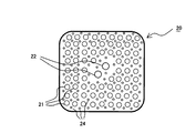
図19は、異物フィルタ機能を有する下部タイプレートの例を示す(例えば特開平7−306284号公報参照)。図19で、燃料棒2とウォータロッド3の下部端栓11、12の下部が、下部タイプレート5のネットワーク部7の挿入孔13を貫通している。ネットワーク部7の下方には、異物フィルタの機能を有する仕切り板20が、下部プレート空洞9を横断してほぼ水平に設けられている。仕切り板20には、図20に示すように、燃料棒2とウォータロッド3の各下部端栓11、12が通る貫通孔21、22のほかに、冷却材が流通し、異物の流通を阻止する小孔24が多数設けられている。
【0013】
図19の構成で、冷却材15は、下部タイプレート入口開口10から下部タイプレート空洞9内に流入し、仕切り板20の小孔24を通り、さらにネットワーク部7の流通孔を通って、チャンネルボックス1内の燃料棒2およびウォータロッド3の周辺へと流れる。このとき、冷却材15中の異物は、仕切り板20の小孔24を通り抜けないので、チャンネルボックス1内への異物流入が阻止される。
【0014】
【発明が解決しようとする課題】
従来の異物フィルタを有する下部タイプレートでは、炉心入口部に達した異物を炉心内に侵入することをある程度の確率で防止することはできた。しかしながら、従来の仕切り板20の小孔24を通ってネットワーク部7の流通孔を通る流れは、ほぼ鉛直上向きの直線状である。このため、特に直線的な細長い異物が冷却材によって流れに対して縦方向に運ばれたときに、これらの流路を通過してしまう可能性がないとはいえなかった。
【0015】
本発明の目的は、特に直線的な細長い異物の捕捉性能にすぐれた下部タイプレートとその組立てを提供することにある。
【0016】
【課題を解決するための手段】
本発明は上記目的を達成するものであって、請求項1の発明は、原子燃料を充填した複数の燃料棒が互いに間隔をあけて格子状に配列されるようにそれらの燃料棒の下部を保持するネットワーク部と、このネットワーク部の周囲から下方に延びてこのネットワーク部の下方に下部タイプレート空洞を形成し、下端に入口開口を有するノズル部と、
前記下部タイプレート空洞内の前記ネットワーク部の下方にほぼ水平に配置されて前記下部タイプレート空洞を上下に区画する仕切り板と、前記仕切り板に設けられ前記複数の燃料棒の下部端栓と複数の筒状フィルタを貫通固定させる穴と、を有し、前記複数の筒状フィルタは、前記仕切り板の下方および上方に開口部を有するとともに上端部は閉じていて前記仕切り板の上方の前記開口部は前記筒状フィルタの側面に設けられていること、を特徴とする。
請求項1の発明によれば、特に直線的な細長い異物の捕捉性能にすぐれた下部タイプレートを提供することができる。
【0017】
また請求項2の発明は、請求項1に記載の原子燃料集合体下部タイプレートにおいて、あらかじめ前記仕切り板に前記筒状フィルタを取り付けた後に、前記仕切り板と、前記ネットワーク部と、前記ノズル部とを互いに結合してなること、を特徴とする。
請求項2の発明によれば、請求項1の発明の作用・効果が得られるほか、かかる下部タイプレートを容易に組み立てることができる。
【0018】
また請求項3の発明は、請求項1または2に記載の原子燃料集合体下部タイプレートにおいて、前記筒状フィルタは、上端に向かって次第に細く形成されていること、を特徴とする。
請求項3の発明によれば、請求項1または2の発明の作用・効果が得られるほか、筒状フィルタを出た後の冷却材の流れが滑らかになる。
【0019】
また請求項4の発明は、請求項1ないし3のいずれかに記載の原子燃料集合体下部タイプレートにおいて、前記筒状フィルタは、前記仕切り板への取り付け部の上方が前記仕切り板への取り付け部の下方よりも細く形成されており、前記仕切り板には、前記仕切り板の上方は貫通しかつ前記仕切り板の下方は貫通しない大きさの穴を有することを特徴とする。
請求項4の発明によれば、請求項1ないし3のいずれかの発明の作用・効果が得られるほか、筒状フィルタを仕切り板で確実に支持することができる。
【0020】
また請求項5の発明は、請求項1ないし4のいずれかに記載の原子燃料集合体下部タイプレートにおいて、前記筒状フィルタの周囲に環状の水平板が取り付けられており、この水平板が前記仕切り板と結合されていること、を特徴とする。請求項5の発明によれば、請求項1ないし4のいずれかの発明の作用・効果が得られるほか、筒状フィルタを仕切り板に取り付ける作業が容易になる。
【0021】
また請求項6の発明は、請求項1ないし5のいずれかに記載の原子燃料集合体下部タイプレートにおいて、前記筒状フィルタは、下端に設けられた下向き開口部と、前記下向き開口部から上方に向かって滑らかに流路面積が縮小する第1の縮流部と、前記縮流部の上方でかつ前記仕切り板の上方に設けられた横向き大開口部と、前記横向き大開口部の上方に設けられ上方に向かって滑らかに流路面積が縮小する第2の縮流部と、前記第2の縮流部の上方に設けられて前記横向き大開口部よりも小さな複数の横向き小開口部と、を有すること、を特徴とする。
【0022】
請求項6の発明によれば、請求項1ないし5のいずれかの発明の作用・効果が得られるほか、何らかの原因で多量の異物が発生した場合にも、横向き大開口部の流路が確保されて燃料部に冷却材が流れるので、安全性が高まる。しかも、通常時は縮流部の効果により異物は横向き大開口部から出ることなく捕捉されることが期待できる。
【0023】
また請求項7の発明は、請求項1ないし6のいずれかに記載の原子燃料集合体下部タイプレートにおいて、前記複数の筒状フィルタの少なくとも一部は、前記格子状に配列された複数の燃料棒同士の間の中央のほぼ真下の位置に配置されていること、を特徴とする。
請求項7の発明によれば、請求項1ないし6のいずれかの発明の作用・効果が得られるほか、下部タイプレート内の冷却材の流れの偏りが比較的小さくなる。
【0024】
また請求項8の発明は、請求項1ないし7のいずれかに記載の原子燃料集合体下部タイプレートにおいて、前記筒状フィルタは前記仕切り板の下方に延びており、前記筒状フィルタの前記仕切り板の下方を相互に連結する連結材をさらに有すること、を特徴とする。
【0025】
請求項8の発明によれば、請求項1ないし7のいずれかの発明の作用・効果が得られるほか、筒状フィルタの取り付けが確実となり、筒状フィルタの全体または一部の脱落の可能性が小さくなる。
【0026】
また請求項9の発明は、請求項1ないし8のいずれかに記載の原子燃料集合体下部タイプレートにおいて、前記燃料棒は、前記仕切り板の下方に延びる下部端栓を有し、前記筒状フィルタは前記仕切り板の下方に延びており、前記筒状フィルタの前記仕切り板の下方と、前記下部端栓の前記仕切り板の下方とを連結する連結材をさらに有すること、を特徴とする。
【0027】
請求項9の発明によれば、請求項1ないし8のいずれかの発明の作用・効果が得られるほか、筒状フィルタの取り付けがさらに確実となり、筒状フィルタの全体または一部の脱落の可能性が小さくなる。
【0028】
また請求項10は、原子燃料を充填した複数の燃料棒が互いに間隔をあけて格子状に配列されるようにそれらの燃料棒の下部を保持するネットワーク部と、このネットワーク部の周囲から下方に延びてこのネットワーク部の下方に下部タイプレート空洞を形成し、下端に入口開口を有するノズル部と、前記下部タイプレート空洞内の前記ネットワーク部の下方にほぼ水平に配置されて前記下部タイプレート空洞を上下に区画する仕切り板と、前記仕切り板に設けられ前記複数の燃料棒の下部端栓と複数の底部部材を挿入固定する穴と、上端部は閉じているとともに側面に開口部を有する複数の筒状フィルタと、を有し、前記底部部材は、前記穴の外側に前記仕切り板の下面に沿って広がる環状のつばと、このつばの内周に接続されて前記穴の上方に延びて上端に開口を持つ筒状部と、からなり、前記筒状フィルタは前記底部部材の前記筒状部を囲むようにして前記仕切り板の上面に立設されていること、を特徴とする。
請求項10の発明によれば、筒状フィルタを仕切り板に取り付ける作業が容易になる。
【0029】
また、請求項11の発明は、原子燃料を充填した複数の燃料棒が互いに間隔をあけて格子状に配列されるようにそれらの燃料棒の下部を保持するネットワーク部と、このネットワーク部の周囲から下方に延びてこのネットワーク部の下方に下部タイプレート空洞を形成し、下端に入口開口を有するノズル部と、前記下部タイプレート空洞内の前記ネットワーク部の下方にほぼ水平に配置されて前記下部タイプレート空洞を上下に区画する仕切り板と、前記仕切り板に設けられ前記複数の燃料棒の下部端栓と複数の筒状フィルタを貫通固定させる穴と、を有し、前記複数の筒状フィルタは、前記仕切り板の下方および上方に開口部を有するとともに上端部は閉じていて前記仕切り板の上方の前記開口部は前記筒状フィルタの側面に設けられている原子燃料集合体下部タイプレートの組立て方法において、前記複数の筒状フィルタを前記仕切り板に取り付ける第1の工程と、前記第1の工程の後に、前記仕切り板と前記ネットワーク部と前記ノズル部とを相互に結合する第2の工程と、を有すること、を特徴とする。
請求項11の発明によれば、特に直線的な細長い異物の捕捉性能にすぐれた下部タイプレートを、容易に組み立てることができる。
【0030】
【発明の実施の形態】
以下、図1〜図17を参照しながら本発明の実施の形態を説明する。ただし、従来の技術あるいは互いに、共通もしくは類似の部分には、共通の符号を付して、重複説明は適宜省略する。
【0031】
まず、図1〜図4を参照して本発明の第1の実施の形態を説明する。この実施の形態では、図1に示すように、下部タイプレートは従来の一体形成のものではなく、ネットワーク部7と、ノズル部8とが別個の部品として構成され、これらの間に挟まれて、水平な板状の仕切り板30が形成されていて、これらが例えば溶接によって接合されている。そして、仕切り板30には、仕切り板30を貫通する多数の筒状フィルタ32が立設されている。なお、図1では、チャンネルボックス1(図18)を示すのを省略している。
【0032】
図2に示すように、筒状フィルタ32は中空の円筒であって、上端33は閉じており、下端34は開いている。寸法は、例えば、直径5mm、高さ50mmである。また、側面の上半部に多数の小孔36が形成されている。小孔36の直径は、例えば2mmである。
【0033】
図3に示すように、筒状フィルタ32は仕切り板30を貫通し、仕切り板30が筒状フィルタ32の中間の高さ位置になるようにして固定されている。小孔36はすべて仕切り板30の上方に位置している。
【0034】
図1および図4からわかるように、仕切り板30には、筒状フィルタ32が格子状に配列されて取り付けられるほか、燃料棒2の下部端栓11が貫通する穴38、およびウォータロッド3の下部端栓12が貫通する穴40が設けられている。仕切り板30における筒状フィルタ32の取り付け穴の直径は筒状フィルタ32の外径とほぼ等しく、筒状フィルタ32のの取り付け部外周から冷却材中の大きな異物が通り抜けないようになっている。また、穴38、40は下部端栓11、12の太さよりもわずかに大きく、貫通部の間隙から冷却材中の大きな異物が通り抜けないようになっている。
【0035】
また、穴38、40の位置は、下部端栓11、12の水平方向の位置、すなわち燃料棒2およびウォータロッド3の水平方向の位置に合わせて配列されている。また、筒状フィルタ32は、互いに隣接する下部端栓11、12のほぼ中央位置に配置されている。
【0036】
この実施の形態の下部タイプレートを組み立てるにあたっては、まず、図3および図4に示すように、仕切り板30に、下部端栓11、12を貫通させる穴38、40や筒状フィルタ32を貫通させる穴などの加工をし、この仕切り板30に筒状フィルタ32を挿入して、これを溶接などにより固定する。その後、筒状フィルタ32を取り付けた仕切り板30をネットワーク部7とノズル部8の間に挟みこむようにして、これらを、例えば溶接によって合体させる。
【0037】
図19に示した従来の下部タイプレートでは、ネットワーク部7、ノズル部8、仕切り板20が初めから一体のものとして鋳造されていたので、仕切り板20に筒状フィルタ32を取り付けるような加工は困難であったが、本実施の形態では、ネットワーク部7、ノズル部8、仕切り板30を初めに別個のものとして作るので、仕切り板30に筒状フィルタ32を取り付けるような加工も容易に実施できる。
【0038】
この実施の形態で、異物を含んだ冷却材15は、図1に示すように、ノズル部8の下端の下部タイプレート入口開口10から下部タイプレート空洞9内に流入する。さらに、冷却材15は筒状フィルタ32の下端34から筒状フィルタ32内に入って小孔36から横方向に流出する(図3参照)。このとき流れの向きが変えられるので、針金状(例えば長さ20〜30mm)の異物は筒状フィルタ32内で捕捉される。また、小片板状の異物も、フィルタ32の下端34で止められる。
【0039】
小孔36を通じて筒状フィルタ32の外側に出た冷却材は、ネットワーク部7の下部端栓11、12の貫通部間にある流路42を通って、燃料棒2およびウォータロッド3の周囲への上昇していく。
【0040】
なお、仕切り板30の穴38、40とこれを貫通する下部端栓11、12の間隙からも若干の冷却材が上方に通り抜けるが、この間隙は小さいので、異物が通り抜けることはない。
上記説明では小孔36の形状を円形としたが、円形のほか、楕円形、半円形、十字形、星形、三日月形、多角形など、任意の形状とすることもできる。
【0041】
また、筒状フィルタ32の形状は、円筒形のほか、多角柱、円錐、多角錐、または、円筒と円錐を直列に繋ぎ合せたもの、あるいは、円筒と多角錐を直列に繋ぎ合せたものなどとすることもできる。
【0042】
次に、図5〜図15により、上記第1の実施の形態の筒状フィルタ32と置き換えることのできる筒状フィルタの他の実施の形態を説明する。筒状フィルタ以外の部分は第1の実施の形態と同様である。
【0043】
図5は、第2の実施の形態の筒状フィルタ42を示すものである。この筒状フィルタ42では、側面の上部のみならず側面全体に多数の小孔36を設けてある。他の構成は第1の実施の形態の筒状フィルタ32と同様である。この実施の形態では、筒状フィルタ42を仕切り板30(図3など参照)に取り付けたときに、仕切り板30の上方のみならず下方にも小孔36が配置される。したがって、冷却材が、筒状フィルタ42の下端34のみならず仕切り板30の下方の小孔36からも筒状フィルタ42に流入できる。したがって、冷却材中の異物による筒状フィルタ42の局所的な流路閉塞の可能性を低下させることができる。
【0044】
図6は、本発明の下部タイプレートの第3の実施の形態の筒状フィルタ44を示すものである。この筒状フィルタ44では、上端部46が円錐状(逆椀状)になっていて、上方に向かって細くなっている。他の構成は第1の実施の形態の筒状フィルタ32と同様である。この実施の形態では、冷却材が小孔36から出た後に上方の下部タイプレートネットワーク部7に向かう流路が滑らかになるので、流動抵抗を低下させることができる。
【0045】
図7は、本発明の下部タイプレートの第4の実施の形態の筒状フィルタ48を示すものである。この筒状フィルタ48は第3の実施の形態の筒状フィルタ44(図6参照)に変更を加えたものであって、筒状フィルタ48の側面に段50があり、段50の下方は太径円筒部52になっている。段50の上方は第3の実施の形態の筒状フィルタ44と同様であって、上端部46が円錐状(逆椀状)になっていて、上方に向かって細くなっている。また、段50の上方に多数の小孔36が設けられている。太径円筒部52の下端34は開放されているが、太径円筒部52の側面は閉じている。
【0046】
この実施の形態では、筒状フィルタ48に段50が形成されているので、筒状フィルタ48を仕切り板30に取り付けるさいに、位置決めが容易である。すなわち、筒状フィルタ48を仕切り板30の下面側から取り付け穴に差込み、筒状フィルタ48の段50が仕切り板30の下面に接触する位置で溶接などにより、筒状フィルタ48を仕切り板30に、例えば溶接によって固定する。
【0047】
図8は、本発明の下部タイプレートの第5の実施の形態の筒状フィルタ54を示すものである。この筒状フィルタ54は第3の実施の形態の筒状フィルタ44(図6参照)に変更を加えたものであって、筒状フィルタ54の下端56は閉じている。そして、筒状フィルタ54の側面には、上部のみならず、下部を含めて全体に多数の小孔36が設けられている。この実施の形態では、第2の実施の形態(図5)と同様に、筒状フィルタ54が仕切り板30の穴に挿入されて固定されたとき、仕切り板30の上方と下方の両方に小孔36が配置される。
【0048】
すなわち、この実施の形態では、ノズル部8の下端の下部タイプレート入口開口10から下部タイプレート空洞9内に流入した冷却材15は、筒状フィルタ54の側面の仕切り板30の下方の小孔36から筒状フィルタ54内に入って、仕切り板30の上方の小孔36から流出する。
【0049】
この実施の形態によれば、筒状フィルタ54の下端56が閉じていることから、冷却材15に異物が含まれている場合に、異物が筒状フィルタ54内に止まり、燃料集合体の取出しの際に異物も炉外に取り出される可能性が高い。すなわち、筒状フィルタの下端が開いている場合は、冷却材の流れが停止したときに、筒状フィルタで捕捉された異物が重力で落下し、下部タイプレート入口開口10を通して、原子炉圧力容器の底部である下部プレナム(図示せず)に堆積する可能性があるが、この実施の形態では、筒状フィルタ54の下端56が閉じていることから、異物が筒状フィルタ54内に止まる。
【0050】
図9は、本発明の下部タイプレートの第6の実施の形態の筒状フィルタ58を示すものである。この筒状フィルタ58は第4の実施の形態(図7)と第5の実施の形態(図8)を組み合わせたものである。すなわち、第4の実施の形態と同様に、筒状フィルタ58の側面の途中に段50が形成され、段50の下方は太径円筒部52になっている。段50の上方は第5の実施の形態の筒状フィルタ54と同様であって、上端部46が円錐状(逆椀状)になっていて、上方に向かって細くなっている。太径円筒部52の下端56は、第5の実施の形態と同様に閉じていて、太径円筒部52の側面に多数の小孔60が形成されている。
【0051】
第4の実施の形態と同様に、段50を仕切り板30の下面と接触するように筒状フィルタ58を仕切り板30に取り付けたとき、太径円筒部52の小孔60は仕切り板30の下方に位置する。
【0052】
図10は、本発明の下部タイプレートの第7の実施の形態の筒状フィルタ62を示すものである。この筒状フィルタ62は第1の実施の形態の筒状フィルタ32(図2)の側面の外側の途中高さ位置に環状水平板64が、例えば溶接によって取り付けられている。その他の構成は筒状フィルタ32と同様である。この実施の形態によれば、筒状フィルタ62にあらかじめ環状水平板64が取り付けられているので、これを仕切り板30に取り付ける際に位置決めが容易であり、例えば環状水平板64仕切り板30に溶接することによって、確実に取り付けることができる。
【0053】
図11は、本発明の下部タイプレートの第8の実施の形態の筒状フィルタ66を示すものである。この筒状フィルタ66は、第3の実施の形態の筒状フィルタ44(図6)に、第7の実施の形態(図10)と同様の環状水平板64を取り付けたものである。この実施の形態によれば、第3の実施の形態と第7の実施の形態の作用・効果を併せ持つことができる。
【0054】
図12(a)は、本発明の下部タイプレートの第9の実施の形態の筒状フィルタ68を示すものである。この筒状フィルタ68は第1の実施の形態の筒状フィルタ32(図2)とほぼ同様の構成のものであるが、これは、仕切り板30の取り付け穴に挿入されるのでなく、取り付け穴を囲む位置で仕切り板30の上面に立設される。このとき仕切り板30の取り付け穴の下方に、図12(b)に示す底部部材70が配置される。底部部材70は、水平な穴明き円板状(円環状)のつば72と、つば72の内周から立ち上がり上方に向かって細くなった筒状部74とを有する。筒状部74の上端は開いている。
【0055】
筒状フィルタ68を仕切り板30に取り付けるにあたっては、まず、筒状フィルタ68取り付け部の仕切り板30の穴(図示せず)に仕切り板30の下方から底部部材70の筒状部74を挿入し、つば72が仕切り板30の下面に密着するようにして、例えば溶接によって、つば72を仕切り板30の下面に固定する。このとき仕切り板30の上面から上方に筒状部74が突出しているので、この筒状部74の外側に筒状フィルタ68を被せるようにして筒状フィルタ68を仕切り板30上面上に立設し、溶接などによって固定する。
【0056】
この実施の形態によれば、つば72を仕切り板30に固定することによって底部部材70が固定され、底部部材70の筒状部74に筒状フィルタ68を被せるようにするので、位置決めが容易であり、しかも仕切り板30に対して筒状フィルタ68を確実に取り付けることができる。
【0057】
図13(a)は、本発明の下部タイプレートの第10の実施の形態の筒状フィルタ76を示すものである。この筒状フィルタ76は第3の実施の形態の筒状フィルタ44(図6)とほぼ同様の構成のものである。ただし、側面に設けられた小孔として円形の小孔36のほかに星形の小孔78も示してある。この筒状フィルタ76は、第9の実施の形態(図12)と同様に、図13(b)に示す底部部材70によって、位置決めされ、仕切り板30の上面に立設されて固定される。なお、図13(b)の底部部材70は図12(b)の底部部材70と同様のものである。
【0058】
図14は、本発明の下部タイプレートの第11の実施の形態の筒状フィルタ80を示すものである。この筒状フィルタ80は、第4の実施の形態(図7)と類似しており、以下に相違点を中心として説明する。段50の高さ(仕切り板30への取り付け時に仕切り板30の高さ位置に相当する)の下方の太径円筒部52の内部は、下端(入口)34から上端(出口)82に向けて次第に細くなっていて、たとえば、下端34では直径10mm、上端82では直径6mmになっている。
【0059】
段50の近傍上方の側面には例えば直径5mmの大型側面円形穴84が設けられている。大型側面円形穴84より上方の側面には直径2mmの多数の小孔36が開いている。また、大型側面円形穴84付側面と小孔36付側面の内面には、穴明き水平板(環状板)85が取り付けられている。環状板85の開口部から上方に向かって細くなる内部テーパ筒86が取り付けられている。内部テーパ筒86の上端は開いている。
段50の上方の流路は例えば直径5mmであり、環状板85の開口部直径は例えば4mmであり、内部テーパ筒86の上端開口部直径は例えば3mmである。
【0060】
この実施の形態の筒状フィルタ80の下端34から流入した冷却材は、上端82を通って上方に向かう。太径円筒部52の内部は流路が次第に細くなっているのでジェット流となる。このため、冷却材中の針金状の異物は大型側面円形穴84から横向きに出て行くことなく上方に向かい、内部テーパ筒86内を上昇する。ここで流れはさらに加速される。
【0061】
また、小片板状の異物は、筒状フィルタ80の下端34で止められる。また、仮に大量の異物が発生した場合には、大型側面円形穴84を通して、異物が排出されるので、流路が閉塞する可能性が低下する。
【0062】
図15は、本発明の下部タイプレートの第12の実施の形態の筒状フィルタ88を示すものである。この筒状フィルタ88は、第11の実施の形態(図14)と類似しており、以下に相違点を中心として説明する。この実施の形態では、流路内の環状板85の代わりに流路外に突出して環状板90が設けられている。この環状板90の開口部から上方に向かって細くなる内部テーパ筒86が取り付けられている点は第11の実施の形態と同様である。
【0063】
この実施の形態では、段50を通り過ぎて上昇する流れが環状板90で急縮小することなく、滑らかに内部テーパ筒86内に入って徐々に縮小する。このため、第11の実施の形態の場合よりも流れが滑らかになる。ここで環状板90は、内部テーパ筒86を取り付けるためのものであって、環状板90を境にして筒状部が上下に分割されており、あらかじめ内部テーパ筒86を取り付けた環状板90を挟み込んで結合する。
なお、この実施の形態では多数の円形の小孔36の代わりに多数の星形の小孔78を採用しているが、異物捕捉の機能としては特に変わりない。
【0064】
図16は、本発明の下部タイプレートの第13の実施の形態を示す。以下、第1の実施の形態(図1等)と異なる点を説明する。この実施の形態では、燃料棒の下部端栓92およびウォータロッドの下部端栓94の、ネットワーク部7より下方の部分が中空になって、流路が形成されており、そこで異物を捕捉できるように構成されている。このように構成することにより、第1の実施の形態と同様に、仕切り板30に取り付けられた筒状フィルタ32で異物捕捉が可能なだけでなく、下部端栓92、94での異物捕捉もできる。
【0065】
なお、下部端栓92、94自体を中空にしてその内部に流路を形成する代わりに、下部端栓92、94にフィルタ部材を取り付けることも同様に可能である。さらに、第2〜第12の実施の形態と、下部端栓92、94の異物捕捉機能を組み合わせることも同様に可能である。
【0066】
図17は、本発明の下部タイプレートの第14の実施の形態を示す。以下、第13の実施の形態(図16)と異なる点を説明する。この実施の形態では、筒状フィルタ32の下端部同士が連結棒96によって連結されており、さらに下部端栓部92、94で固定されている。このような構成により、筒状フィルタ32が確実に固定されるので、筒状フィルタ32と仕切り板30との溶接点数を減らすこともできる。さらに、仮に筒状フィルタ32の一部が損傷した場合でも、異物となって冷却材とともに流れることを抑制または防止することができる。
【0067】
なお、筒状フィルタ32の下端部を相互に連結棒96で結合することと、筒状フィルタ32の下端部を下部端栓部92、94で固定することは、どちらか一方だけ採用することもできる。
また、筒状フィルタを連結棒などによって連結する構造は、上記第1〜第13の実施の形態いずれにも適用することが可能である。
【0068】
【発明の効果】
以上述べたように、本発明によれば、燃料集合体下部タイプレートで異物を捕捉することの確実性を向上させることができる。異物が原因となる燃料破損に対する信頼性が向上し、プラントの運転性能が改善される。
【図面の簡単な説明】
【図1】本発明に係る燃料集合体下部タイプレートの第1の実施の形態の模式的立断面図。
【図2】図1の筒状フィルタを単独で取り出して示す斜視図。
【図3】図1の筒状フィルタを1個だけ仕切り板に取り付けた状態を示す模式的立面図。
【図4】図1の筒状フィルタを仕切り板に取り付けた状態を示す模式的平面図。
【図5】本発明に係る燃料集合体下部タイプレートの第2の実施の形態における筒状フィルタを単独で取り出して示す斜視図。
【図6】本発明に係る燃料集合体下部タイプレートの第3の実施の形態における筒状フィルタを単独で取り出して示す斜視図。
【図7】本発明に係る燃料集合体下部タイプレートの第4の実施の形態における筒状フィルタを単独で取り出して示す斜視図。
【図8】本発明に係る燃料集合体下部タイプレートの第5の実施の形態における筒状フィルタを単独で取り出して示す斜視図。
【図9】本発明に係る燃料集合体下部タイプレートの第6の実施の形態における筒状フィルタを単独で取り出して示す斜視図。
【図10】本発明に係る燃料集合体下部タイプレートの第7の実施の形態における筒状フィルタを単独で取り出して示す斜視図。
【図11】本発明に係る燃料集合体下部タイプレートの第8の実施の形態における筒状フィルタを単独で取り出して示す斜視図。
【図12】(a)は本発明に係る燃料集合体下部タイプレートの第9の実施の形態における筒状フィルタを単独で取り出して示す斜視図、(b)は(a)の筒状フィルタと組み合わせて用いる底部部材の斜視図。
【図13】(a)は本発明に係る燃料集合体下部タイプレートの第10の実施の形態における筒状フィルタを単独で取り出して示す斜視図、(b)は(a)の筒状フィルタと組み合わせて用いる底部部材の斜視図。
【図14】本発明に係る燃料集合体下部タイプレートの第11の実施の形態における筒状フィルタを単独で取り出して示す斜視図。
【図15】本発明に係る燃料集合体下部タイプレートの第12の実施の形態における筒状フィルタを単独で取り出して示す斜視図。
【図16】本発明に係る燃料集合体下部タイプレートの第13の実施の形態の模式的立断面図。
【図17】本発明に係る燃料集合体下部タイプレートの第14の実施の形態の模式的立断面図。
【図18】従来の燃料集合体の全体立断面図。
【図19】図18の下部タイプレート付近の拡大立断面図。
【図20】図19の仕切り板だけを取り出して示す平面図。
【符号の説明】
1…チャンネルボックス、2…燃料棒、3…ウォータロッド、4…上部タイプレート、5…下部タイプレート、6…スペーサ、7…ネットワーク部、8…ノズル部、9…下部タイプレート空洞、10…下部タイプレート入口開口、11…燃料棒の下部端栓、12…ウォータロッドの下部端栓、13…挿入孔、15…冷却材、17…リークホール、20…仕切り板、21…燃料棒の下部端栓が通る貫通孔、22…ウォータロッドの下部端栓が通る貫通孔、24…小孔、26…ウォータロッドの入口孔、27…ウォータロッドの出口孔、30…仕切り板、32…筒状フィルタ、33…上端、34…下端、36…小孔、38…穴、40…穴、42…筒状フィルタ、44…筒状フィルタ、46…上端部、48…筒状フィルタ、50…段、52…太径円筒部、54…筒状フィルタ、56…下端、60…小孔、62…筒状フィルタ、64…環状水平板、66…筒状フィルタ、68…筒状フィルタ、70…底部部材、72…つば、74…筒状部、76…筒状フィルタ、78…星形の小孔、80…筒状フィルタ、82…上端(出口)、84…大型側面円形穴、85…穴明き水平板(環状板)、86…内部テーパ筒、88…筒状フィルタ、90…環状板、92…燃料棒の下部端栓、94ウォータロッドの下部端栓、96…連結棒。[0001]
BACKGROUND OF THE INVENTION
The present invention relates to a lower tie plate of a fuel assembly for a light water reactor, and more particularly, to a lower tie plate that can prevent or suppress foreign matters mixed in a coolant from flowing into a fuel part. The present invention also relates to a method for assembling the lower tie plate.
[0002]
[Prior art]
As shown in FIG. 18, for example, the fuel assembly for a boiling water reactor has a
[0003]
The
[0004]
Each
[0005]
On the other hand, the
[0006]
The lower end of the
[0007]
The
[0008]
In the fuel assembly of FIG. 18, the
[0009]
As shown in FIG. 18, a
[0010]
Some fuel assemblies with high performance in recent years add a filter function for the purpose of preventing foreign matters from entering the fuel assemblies. For example, there is a design that increases the resistance to flow (that is, high-pressure loss) by making the diameter of the flow hole in the network part of the lower tie plate smaller than the conventional one, thereby improving the stability of the core. However, this also serves as a foreign matter filter.
[0011]
Foreign materials that are expected to enter the fuel assembly include gold dust slightly left in the reactor primary system at the time of plant construction, broken metal brushes during equipment cleaning, and fragments when equipment is damaged. Assumed. The shape is also expected to vary widely, such as a plate shape, a string-wound spring shape (spiral shape), and a wire shape (linear shape).
[0012]
FIG. 19 shows an example of a lower tie plate having a foreign matter filter function (see, for example, JP-A-7-306284). In FIG. 19, the lower ends of the
[0013]
In the configuration of FIG. 19, the
[0014]
[Problems to be solved by the invention]
In the lower tie plate having the conventional foreign matter filter, the foreign matter that has reached the core inlet portion can be prevented with a certain probability from entering the core. However, the flow passing through the
[0015]
SUMMARY OF THE INVENTION An object of the present invention is to provide a lower tie plate and an assembly thereof that are particularly excellent in the ability to capture linear and elongated foreign objects.
[0016]
[Means for Solving the Problems]
The present invention achieves the above-mentioned object, and the invention of
A partition plate arranged substantially horizontally below the network part in the lower tie plate cavity and partitioning the lower tie plate cavity up and down;A hole provided in the partition plate for penetrating and fixing lower end plugs of the plurality of fuel rods and a plurality of cylindrical filters;HaveThe plurality of cylindrical filters have openings below and above the partition plate.The upper end portion is closed, and the opening above the partition plate is provided on a side surface of the cylindrical filter.
According to the first aspect of the present invention, it is possible to provide a lower tie plate that is particularly excellent in the ability to capture linear and elongated foreign matter.
[0017]
The invention of
According to the invention of
[0018]
According to a third aspect of the present invention, in the nuclear fuel assembly lower tie plate according to the first or second aspect, the cylindrical filter is formed so as to be gradually narrowed toward the upper end.
According to the invention of
[0019]
According to a fourth aspect of the present invention, in the nuclear fuel assembly lower tie plate according to any one of the first to third aspects, the tubular filter is attached to the partition plate above an attachment portion to the partition plate. The partition plate has a size that penetrates above the partition plate and does not penetrate below the partition plate.holeIt is characterized by having.
According to the invention of claim 4, in addition to the effects and advantages of the invention of any one of
[0020]
The invention of
[0021]
The invention of
[0022]
According to the invention of
[0023]
The invention of
According to the invention of
[0024]
The invention of
[0025]
According to the invention of
[0026]
The ninth aspect of the present invention is the nuclear fuel assembly lower tie plate according to any one of the first to eighth aspects, wherein the fuel rod has a lower end plug extending below the partition plate, and the cylindrical shape. The filter extends below the partition plate, and further includes a connecting member that connects the lower portion of the partition plate of the cylindrical filter and the lower portion of the partition plate of the lower end plug.
[0027]
According to the ninth aspect of the invention, the effects and advantages of any of the first to eighth aspects of the invention can be obtained, and the attachment of the tubular filter is further ensured, and the whole or a part of the tubular filter can be removed. The sex becomes smaller.
[0028]
Further, the present invention provides a network unit that holds the lower portions of the fuel rods filled with nuclear fuel so that the fuel rods are arranged in a lattice pattern at intervals, and from the periphery of the network unit to the lower side. A lower tie plate cavity that extends to form a lower tie plate cavity below the network portion, has an inlet opening at a lower end, and is disposed substantially horizontally below the network portion in the lower tie plate cavity. A partition plate that divides the upper and lower parts, and a hole provided in the partition plate for inserting and fixing lower end plugs of the plurality of fuel rods and a plurality of bottom members,A plurality of cylindrical filters having an upper end closed and an opening on a side surface;And the bottom member has an annular collar extending along the lower surface of the partition plate outside the hole, and a cylinder connected to the inner periphery of the collar and extending above the hole and having an opening at the upper end. And the cylindrical filter is erected on the upper surface of the partition plate so as to surround the cylindrical portion of the bottom member.
According to the invention of
[0029]
The invention according to
According to the eleventh aspect of the present invention, it is possible to easily assemble a lower tie plate that is particularly excellent in the ability to capture linear and elongated foreign matters.
[0030]
DETAILED DESCRIPTION OF THE INVENTION
Hereinafter, embodiments of the present invention will be described with reference to FIGS. However, a common code | symbol is attached | subjected to a prior art or a mutually or common part, and duplication description is abbreviate | omitted suitably.
[0031]
First, a first embodiment of the present invention will be described with reference to FIGS. In this embodiment, as shown in FIG. 1, the lower tie plate is not a conventional one-piece type, but the
[0032]
As shown in FIG. 2, the
[0033]
As shown in FIG. 3, the
[0034]
As can be seen from FIG. 1 and FIG. 4,
[0035]
The positions of the
[0036]
In assembling the lower tie plate of this embodiment, first, as shown in FIGS. 3 and 4, the
[0037]
In the conventional lower tie plate shown in FIG. 19, the
[0038]
In this embodiment, the
[0039]
The coolant that has flowed out of the
[0040]
A small amount of coolant passes through the gaps between the
In the above description, the
[0041]
The
[0042]
Next, another embodiment of the cylindrical filter that can replace the
[0043]
FIG. 5 shows a
[0044]
FIG. 6 shows a
[0045]
FIG. 7 shows a
[0046]
In this embodiment, since the
[0047]
FIG. 8 shows a
[0048]
That is, in this embodiment, the
[0049]
According to this embodiment, since the
[0050]
FIG. 9 shows a
[0051]
Similarly to the fourth embodiment, when the
[0052]
FIG. 10 shows a
[0053]
FIG. 11 shows a
[0054]
FIG. 12A shows a
[0055]
In attaching the
[0056]
According to this embodiment, the
[0057]
FIG. 13A shows a
[0058]
FIG. 14 shows a
[0059]
A large side
The flow path above the
[0060]
The coolant that has flowed in from the
[0061]
Further, the small plate-like foreign matter is stopped at the
[0062]
FIG. 15 shows a
[0063]
In this embodiment, the flow rising after passing through the
In this embodiment, a large number of star-shaped
[0064]
FIG. 16 shows a thirteenth embodiment of the lower tie plate of the present invention. Hereinafter, a different point from 1st Embodiment (FIG. 1 etc.) is demonstrated. In this embodiment, the
[0065]
Instead of hollowing the lower end plugs 92 and 94 themselves and forming a flow path therein, it is possible to attach a filter member to the lower end plugs 92 and 94 as well. Furthermore, it is also possible to combine the second to twelfth embodiments with the foreign matter capturing function of the lower end plugs 92 and 94.
[0066]
FIG. 17 shows a fourteenth embodiment of the lower tie plate of the present invention. Hereinafter, differences from the thirteenth embodiment (FIG. 16) will be described. In this embodiment, the lower ends of the
[0067]
It should be noted that only one of the lower end portions of the
Moreover, the structure which connects a cylindrical filter with a connection rod etc. is applicable to any of the said 1st-13th embodiment.
[0068]
【The invention's effect】
As described above, according to the present invention, it is possible to improve the certainty of capturing foreign matter with the fuel assembly lower tie plate. The reliability with respect to the fuel breakage caused by the foreign matter is improved, and the operation performance of the plant is improved.
[Brief description of the drawings]
FIG. 1 is a schematic vertical sectional view of a first embodiment of a fuel assembly lower tie plate according to the present invention.
FIG. 2 is a perspective view showing the cylindrical filter of FIG.
3 is a schematic elevation view showing a state in which only one cylindrical filter of FIG. 1 is attached to a partition plate.
4 is a schematic plan view showing a state where the cylindrical filter of FIG. 1 is attached to a partition plate. FIG.
FIG. 5 is a perspective view showing a cylindrical filter taken out independently in a second embodiment of a fuel assembly lower tie plate according to the present invention.
FIG. 6 is a perspective view showing a cylindrical filter taken out independently in a third embodiment of a fuel assembly lower tie plate according to the present invention.
FIG. 7 is a perspective view showing a cylindrical filter taken out independently in a fourth embodiment of a fuel assembly lower tie plate according to the present invention.
FIG. 8 is a perspective view showing a cylindrical filter taken out independently in a fifth embodiment of a fuel assembly lower tie plate according to the present invention.
FIG. 9 is a perspective view showing a cylindrical filter taken out independently in a sixth embodiment of a fuel assembly lower tie plate according to the present invention.
FIG. 10 is a perspective view showing a single tubular filter taken out in a seventh embodiment of a fuel assembly lower tie plate according to the present invention.
FIG. 11 is a perspective view showing a cylindrical filter taken out independently from an eighth embodiment of a fuel assembly lower tie plate according to the present invention.
FIG. 12 (a) is a perspective view showing a cylindrical filter in the ninth embodiment of the fuel assembly lower tie plate according to the present invention, and FIG. 12 (b) is a perspective view showing the cylindrical filter of FIG. The perspective view of the bottom part member used in combination.
FIG. 13 (a) is a perspective view showing the tubular filter in the tenth embodiment of the fuel assembly lower tie plate according to the present invention, and FIG. 13 (b) is a perspective view showing the tubular filter of FIG. The perspective view of the bottom part member used in combination.
FIG. 14 is a perspective view showing a cylindrical filter alone taken out and shown in an eleventh embodiment of a fuel assembly lower tie plate according to the present invention.
FIG. 15 is a perspective view showing a cylindrical filter taken out independently in a twelfth embodiment of a fuel assembly lower tie plate according to the present invention.
FIG. 16 is a schematic sectional elevation view of a thirteenth embodiment of a fuel assembly lower tie plate according to the present invention.
FIG. 17 is a schematic sectional elevation view of a fourteenth embodiment of a fuel assembly lower tie plate according to the present invention.
FIG. 18 is an overall vertical sectional view of a conventional fuel assembly.
FIG. 19 is an enlarged vertical sectional view in the vicinity of the lower tie plate in FIG. 18;
20 is a plan view showing only the partition plate of FIG.
[Explanation of symbols]
DESCRIPTION OF
Claims (11)
このネットワーク部の周囲から下方に延びてこのネットワーク部の下方に下部タイプレート空洞を形成し、下端に入口開口を有するノズル部と、
前記下部タイプレート空洞内の前記ネットワーク部の下方にほぼ水平に配置されて前記下部タイプレート空洞を上下に区画する仕切り板と、
前記仕切り板に設けられ前記複数の燃料棒の下部端栓と複数の筒状フィルタを貫通固定させる穴と、を有し、
前記複数の筒状フィルタは、前記仕切り板の下方および上方に開口部を有するとともに上端部は閉じていて前記仕切り板の上方の前記開口部は前記筒状フィルタの側面に設けられていること、
を特徴とする原子燃料集合体下部タイプレート。A network unit for holding a plurality of fuel rods filled with nuclear fuel and holding the lower portions of the fuel rods so that the fuel rods are arranged in a lattice pattern at intervals from each other;
A nozzle part extending downward from the periphery of the network part to form a lower tie plate cavity below the network part, and having an inlet opening at the lower end;
A partition plate arranged substantially horizontally below the network part in the lower tie plate cavity and partitioning the lower tie plate cavity up and down;
A lower end plug of the plurality of fuel rods provided in the partition plate and a hole for penetrating and fixing the plurality of cylindrical filters;
The plurality of cylindrical filters have openings below and above the partition plate, the upper end thereof is closed, and the opening above the partition plate is provided on a side surface of the cylindrical filter;
A nuclear fuel assembly lower tie plate characterized by
前記筒状フィルタは、前記仕切り板への取り付け部の上方が前記仕切り板への取り付け部の下方よりも細く形成されており、
前記仕切り板には、前記仕切り板の上方は貫通しかつ前記仕切り板の下方は貫通しない大きさの穴を有すること、
を特徴とする原子燃料集合体下部タイプレート。In the nuclear fuel assembly lower tie plate according to any one of claims 1 to 3,
The cylindrical filter is formed such that the upper part of the attachment part to the partition plate is narrower than the lower part of the attachment part to the partition plate,
The partition plate has a hole having a size that penetrates above the partition plate and does not penetrate below the partition plate;
A nuclear fuel assembly lower tie plate characterized by
前記筒状フィルタは、下端に設けられた下向き開口部と、前記下向き開口部から上方に向かって滑らかに流路面積が縮小する第1の縮流部と、前記縮流部の上方でかつ前記仕切り板の上方に設けられた横向き大開口部と、前記横向き大開口部の上方に設けられ上方に向かって滑らかに流路面積が縮小する第2の縮流部と、前記第2の縮流部の上方に設けられて前記横向き大開口部よりも小さな複数の横向き小開口部と、を有すること、
を特徴とする原子燃料集合体下部タイプレート。The nuclear fuel assembly lower tie plate according to any one of claims 1 to 5 ,
The cylindrical filter includes a downward opening provided at a lower end, a first flow-reducing portion whose flow area is smoothly reduced upward from the downward opening, the upper portion of the flow-reducing portion, and the A laterally large opening provided above the partition plate; a second contracted portion provided above the laterally large opening and having a flow path area smoothly reduced upward; and the second contracted flow A plurality of laterally small openings that are provided above the portion and are smaller than the laterally large openings,
A nuclear fuel assembly lower tie plate characterized by
前記燃料棒は、前記仕切り板の下方に延びる下部端栓を有し、
前記筒状フィルタは前記仕切り板の下方に延びており、前記筒状フィルタの前記仕切り板の下方と、前記下部端栓の前記仕切り板の下方とを連結する連結材をさらに有すること、
を特徴とする原子燃料集合体下部タイプレート。The nuclear fuel assembly lower tie plate according to any one of claims 1 to 8 ,
The fuel rod has a lower end plug extending below the partition plate;
The cylindrical filter extends below the partition plate, and further includes a connecting material that connects the lower portion of the partition plate of the cylindrical filter and the lower portion of the partition plate of the lower end plug,
A nuclear fuel assembly lower tie plate characterized by
このネットワーク部の周囲から下方に延びてこのネットワーク部の下方に下部タイプレート空洞を形成し、下端に入口開口を有するノズル部と、
前記下部タイプレート空洞内の前記ネットワーク部の下方にほぼ水平に配置されて前記下部タイプレート空洞を上下に区画する仕切り板と、
前記仕切り板に設けられ前記複数の燃料棒の下部端栓と複数の底部部材を挿入固定する穴と、
上端部は閉じているとともに側面に開口部を有する複数の筒状フィルタと、を有し、
前記底部部材は、前記穴の外側に前記仕切り板の下面に沿って広がる環状のつばと、このつばの内周に接続されて前記穴の上方に延びて上端に開口を持つ筒状部と、からなり、前記筒状フィルタは前記底部部材の前記筒状部を囲むようにして前記仕切り板の上面に立設されていること、
を特徴とする原子燃料集合体下部タイプレート。A network unit for holding a plurality of fuel rods filled with nuclear fuel and holding the lower portions of the fuel rods so that the fuel rods are arranged in a lattice pattern at intervals from each other;
A nozzle part extending downward from the periphery of the network part to form a lower tie plate cavity below the network part, and having an inlet opening at the lower end;
A partition plate arranged substantially horizontally below the network part in the lower tie plate cavity and partitioning the lower tie plate cavity up and down;
A hole provided in the partition plate for inserting and fixing lower end plugs of the plurality of fuel rods and a plurality of bottom members;
A plurality of cylindrical filters having an upper end closed and a side opening ;
The bottom member has an annular collar that extends along the lower surface of the partition plate outside the hole, and a cylindrical part that is connected to the inner periphery of the collar and extends above the hole and has an opening at the upper end. The cylindrical filter is erected on the upper surface of the partition plate so as to surround the cylindrical portion of the bottom member,
A nuclear fuel assembly lower tie plate characterized by
このネットワーク部の周囲から下方に延びてこのネットワーク部の下方に下部タイプレート空洞を形成し、下端に入口開口を有するノズル部と、
前記下部タイプレート空洞内の前記ネットワーク部の下方にほぼ水平に配置されて前記下部タイプレート空洞を上下に区画する仕切り板と、
前記仕切り板に設けられ前記複数の燃料棒の下部端栓と複数の筒状フィルタを貫通固定させる穴と、を有し、
前記複数の筒状フィルタは、前記仕切り板の下方および上方に開口部を有するとともに上端部は閉じていて前記仕切り板の上方の前記開口部は前記筒状フィルタの側面に設けられている原子燃料集合体下部タイプレートの組立て方法において、
前記筒状フィルタを前記仕切り板に取り付ける第1の工程と、
前記第1の工程の後に、前記仕切り板と前記ネットワーク部と前記ノズル部とを相互に結合する第2の工程と、
を有すること、を特徴とする原子燃料集合体下部タイプレートの組立て方法。A network unit for holding a plurality of fuel rods filled with nuclear fuel and holding the lower portions of the fuel rods so that the fuel rods are arranged in a lattice pattern at intervals from each other;
A nozzle part extending downward from the periphery of the network part to form a lower tie plate cavity below the network part, and having an inlet opening at the lower end;
A partition plate arranged substantially horizontally below the network part in the lower tie plate cavity and partitioning the lower tie plate cavity up and down;
A lower end plug of the plurality of fuel rods provided in the partition plate and a hole for penetrating and fixing the plurality of cylindrical filters;
The plurality of cylindrical filters have an opening below and above the partition plate, and an upper end is closed, and the opening above the partition plate is provided on a side surface of the cylindrical filter. In the assembly method of the lower assembly tie plate,
A first step of attaching the tubular filter to the partition plate;
After the first step, a second step of coupling the partition plate, the network unit, and the nozzle unit to each other;
A method for assembling a nuclear fuel assembly lower tie plate characterized by comprising:
Priority Applications (4)
| Application Number | Priority Date | Filing Date | Title |
|---|---|---|---|
| JP2001390855A JP4006678B2 (en) | 2001-12-25 | 2001-12-25 | Nuclear fuel assembly lower tie plate and assembly method thereof |
| US10/313,032 US6847695B2 (en) | 2001-12-25 | 2002-12-06 | Nuclear fuel assembly lower tie-plate and method of its assembling |
| DE10259706A DE10259706B4 (en) | 2001-12-25 | 2002-12-19 | Lower armature plate of a nuclear fuel cartridge and method of assembling same |
| SE0203854A SE531645C2 (en) | 2001-12-25 | 2002-12-23 | Lower anchor plate for a nuclear fuel cartridge with screen plate and tubular filters |
Applications Claiming Priority (1)
| Application Number | Priority Date | Filing Date | Title |
|---|---|---|---|
| JP2001390855A JP4006678B2 (en) | 2001-12-25 | 2001-12-25 | Nuclear fuel assembly lower tie plate and assembly method thereof |
Publications (2)
| Publication Number | Publication Date |
|---|---|
| JP2003194979A JP2003194979A (en) | 2003-07-09 |
| JP4006678B2 true JP4006678B2 (en) | 2007-11-14 |
Family
ID=19188452
Family Applications (1)
| Application Number | Title | Priority Date | Filing Date |
|---|---|---|---|
| JP2001390855A Expired - Lifetime JP4006678B2 (en) | 2001-12-25 | 2001-12-25 | Nuclear fuel assembly lower tie plate and assembly method thereof |
Country Status (4)
| Country | Link |
|---|---|
| US (1) | US6847695B2 (en) |
| JP (1) | JP4006678B2 (en) |
| DE (1) | DE10259706B4 (en) |
| SE (1) | SE531645C2 (en) |
Families Citing this family (14)
| Publication number | Priority date | Publication date | Assignee | Title |
|---|---|---|---|---|
| US7161557B2 (en) * | 2002-04-08 | 2007-01-09 | Clearcube Technology, Inc. | Selectively updating a display in a multi-display system |
| JP4090940B2 (en) * | 2003-05-13 | 2008-05-28 | 株式会社グローバル・ニュークリア・フュエル・ジャパン | Lower tie plate, its assembly method and fuel assembly |
| DE102004059195B3 (en) * | 2004-12-09 | 2006-02-23 | Framatome Anp Gmbh | Fuel element for a boiling water nuclear reactor, comprises a foot, a sieve plate, a fuel element head and a bundle of longitudinal fuel rods |
| DE102006038748B3 (en) * | 2006-07-22 | 2008-02-28 | Areva Np Gmbh | Device for removing solid particles from the circulating in the primary circuit of a nuclear reactor cooling medium |
| FR2910170B1 (en) * | 2006-12-13 | 2009-04-03 | Areva Np Sas | LOWER CAP WITH AN ANTI-DEBRIS DEVICE FOR CHICAN NUCLEAR FUEL ASSEMBLY AND CORRESPONDING ASSEMBLY |
| US8116423B2 (en) | 2007-12-26 | 2012-02-14 | Thorium Power, Inc. | Nuclear reactor (alternatives), fuel assembly of seed-blanket subassemblies for nuclear reactor (alternatives), and fuel element for fuel assembly |
| KR101474864B1 (en) | 2007-12-26 | 2014-12-19 | 토륨 파워 인코포레이티드 | Nuclear reactor(variants), fuel assembly consisting of driver-breeding modules for a nuclear reactor(variants) and a fuel cell for a fuel assembly |
| CA2946210C (en) | 2008-12-25 | 2019-02-12 | Thorium Power, Inc. | A light-water reactor fuel assembly and fuel element thereof |
| US10170207B2 (en) | 2013-05-10 | 2019-01-01 | Thorium Power, Inc. | Fuel assembly |
| US10192644B2 (en) | 2010-05-11 | 2019-01-29 | Lightbridge Corporation | Fuel assembly |
| WO2011143172A1 (en) | 2010-05-11 | 2011-11-17 | Thorium Power, Inc. | Fuel assembly with metal fuel alloy kernel and method of manufacturing thereof |
| KR20140111277A (en) | 2011-12-12 | 2014-09-18 | 도미니온 엔지니어링 인코포레이티드 | Particulate removal system |
| UA127699C2 (en) * | 2016-09-06 | 2023-12-06 | Вестінгхаус Електрік Свіден Аб | A fuel assembly |
| US10923237B2 (en) * | 2017-08-28 | 2021-02-16 | Global Nuclear Fuel—Americas, LLC | Debris filters for nuclear fuel assembly and method of using the same |
Family Cites Families (13)
| Publication number | Priority date | Publication date | Assignee | Title |
|---|---|---|---|---|
| FR1213496A (en) * | 1958-08-08 | 1960-04-01 | Commissariat Energie Atomique | Water and vapor separator cyclone for boiling water atomic reactor cell |
| CA1032668A (en) * | 1974-05-20 | 1978-06-06 | John M. Shallenberger | Modular in-core flow filter for a nuclear reactor |
| US5390221A (en) | 1993-08-23 | 1995-02-14 | General Electric Company | Debris filters with flow bypass for boiling water reactors |
| JPH07159567A (en) | 1993-12-13 | 1995-06-23 | Toshiba Corp | Fuel assembly |
| JP3079877B2 (en) * | 1993-12-27 | 2000-08-21 | 株式会社日立製作所 | Fuel assembly |
| US5488634A (en) | 1994-02-10 | 1996-01-30 | General Electric Company | Lower tie plate debris catcher for a nuclear reactor |
| US5481578A (en) * | 1994-06-24 | 1996-01-02 | General Electric Company | Perforated tube debris catcher for a nuclear reactor |
| US5539793A (en) * | 1994-10-27 | 1996-07-23 | General Electric Company | Lower tie plate debris catcher for a nuclear reactor |
| SE517867C2 (en) * | 1995-10-12 | 2002-07-23 | Gen Electric | Water rod in a fuel assembly belonging to a boiling water reactor |
| JPH1123763A (en) | 1997-07-02 | 1999-01-29 | Hitachi Ltd | Lower tie plate of fuel assembly |
| JP3778787B2 (en) | 2000-08-21 | 2006-05-24 | 原子燃料工業株式会社 | Lower tie plate of boiling water reactor fuel assembly |
| GB2380874B (en) * | 2001-10-10 | 2004-02-04 | Zarlink Semiconductor Ltd | A polar loop transmitter |
| US7042958B2 (en) * | 2003-06-04 | 2006-05-09 | Tropian, Inc. | Digital time alignment in a polar modulator |
-
2001
- 2001-12-25 JP JP2001390855A patent/JP4006678B2/en not_active Expired - Lifetime
-
2002
- 2002-12-06 US US10/313,032 patent/US6847695B2/en not_active Expired - Fee Related
- 2002-12-19 DE DE10259706A patent/DE10259706B4/en not_active Expired - Fee Related
- 2002-12-23 SE SE0203854A patent/SE531645C2/en unknown
Also Published As
| Publication number | Publication date |
|---|---|
| DE10259706B4 (en) | 2008-11-20 |
| US20030128798A1 (en) | 2003-07-10 |
| SE0203854D0 (en) | 2002-12-23 |
| SE531645C2 (en) | 2009-06-16 |
| DE10259706A1 (en) | 2003-07-10 |
| SE0203854L (en) | 2003-06-26 |
| JP2003194979A (en) | 2003-07-09 |
| US6847695B2 (en) | 2005-01-25 |
Similar Documents
| Publication | Publication Date | Title |
|---|---|---|
| JP4006678B2 (en) | Nuclear fuel assembly lower tie plate and assembly method thereof | |
| CN101174480B (en) | Lower and upper end plugs of an annular fuel rod | |
| JP5445946B2 (en) | Bottom end piece having an anti-debris device with a baffle for a nuclear fuel assembly and the nuclear fuel assembly | |
| JP2014134546A (en) | Fuel assembly | |
| EP0422950A1 (en) | Nuclear fuel assembly with debris filter | |
| US5219517A (en) | Fuel assembly for a boiling water nuclear reactor | |
| JPH07306280A (en) | Lattice structure for capturing broken piece in fuel bundle of boiling water reactor and fuel bundle of boiling water reactor | |
| JPH1090459A (en) | Pwr fuel assembly | |
| EP2164076A1 (en) | Filter for catching particles in the coolant fluid of a nuclear reactor | |
| JPH03255984A (en) | Fuel assembly for boiling water reactor | |
| KR20190121858A (en) | Nuclear Fuel Debris Filtration Lower Nozzle | |
| KR101826045B1 (en) | Bottom nozzle providing with insertable filtering device for nuclear fuel assembly | |
| JP4076010B2 (en) | Fuel assembly | |
| JP4090940B2 (en) | Lower tie plate, its assembly method and fuel assembly | |
| JP3527493B2 (en) | Fuel assembly | |
| US5471514A (en) | Fuel element for a light-water nuclear reactor | |
| JPH09211162A (en) | Lower tieplate of fuel assembly | |
| JP4282785B2 (en) | Fuel assembly | |
| JP2002062392A (en) | Lower tie-plate of fuel assembly for boiling water reactor | |
| TWI739852B (en) | A fuel assembly | |
| US20220344065A1 (en) | Debris filter for a nuclear fuel assembly bottom end part and method of manufacturing such a debris filter | |
| JP2505813B2 (en) | Control rod guide tube | |
| JPH0968585A (en) | Fuel assembly for reactor | |
| US20050157837A1 (en) | Distributed clumping of part-length rods for a reactor fuel bundle | |
| JP2003121579A (en) | Fuel support metal fittings |
Legal Events
| Date | Code | Title | Description |
|---|---|---|---|
| A621 | Written request for application examination |
Free format text: JAPANESE INTERMEDIATE CODE: A621 Effective date: 20041124 |
|
| A131 | Notification of reasons for refusal |
Free format text: JAPANESE INTERMEDIATE CODE: A131 Effective date: 20070227 |
|
| A521 | Request for written amendment filed |
Free format text: JAPANESE INTERMEDIATE CODE: A523 Effective date: 20070402 |
|
| RD02 | Notification of acceptance of power of attorney |
Free format text: JAPANESE INTERMEDIATE CODE: A7422 Effective date: 20070426 |
|
| A131 | Notification of reasons for refusal |
Free format text: JAPANESE INTERMEDIATE CODE: A131 Effective date: 20070508 |
|
| A521 | Request for written amendment filed |
Free format text: JAPANESE INTERMEDIATE CODE: A523 Effective date: 20070531 |
|
| A131 | Notification of reasons for refusal |
Free format text: JAPANESE INTERMEDIATE CODE: A131 Effective date: 20070626 |
|
| A521 | Request for written amendment filed |
Free format text: JAPANESE INTERMEDIATE CODE: A523 Effective date: 20070720 |
|
| TRDD | Decision of grant or rejection written | ||
| A01 | Written decision to grant a patent or to grant a registration (utility model) |
Free format text: JAPANESE INTERMEDIATE CODE: A01 Effective date: 20070816 |
|
| A61 | First payment of annual fees (during grant procedure) |
Free format text: JAPANESE INTERMEDIATE CODE: A61 Effective date: 20070816 |
|
| FPAY | Renewal fee payment (event date is renewal date of database) |
Free format text: PAYMENT UNTIL: 20100907 Year of fee payment: 3 |
|
| R150 | Certificate of patent or registration of utility model |
Ref document number: 4006678 Country of ref document: JP Free format text: JAPANESE INTERMEDIATE CODE: R150 Free format text: JAPANESE INTERMEDIATE CODE: R150 |
|
| FPAY | Renewal fee payment (event date is renewal date of database) |
Free format text: PAYMENT UNTIL: 20110907 Year of fee payment: 4 |
|
| R250 | Receipt of annual fees |
Free format text: JAPANESE INTERMEDIATE CODE: R250 |
|
| FPAY | Renewal fee payment (event date is renewal date of database) |
Free format text: PAYMENT UNTIL: 20110907 Year of fee payment: 4 |
|
| FPAY | Renewal fee payment (event date is renewal date of database) |
Free format text: PAYMENT UNTIL: 20110907 Year of fee payment: 4 |
|
| FPAY | Renewal fee payment (event date is renewal date of database) |
Free format text: PAYMENT UNTIL: 20110907 Year of fee payment: 4 |
|
| FPAY | Renewal fee payment (event date is renewal date of database) |
Free format text: PAYMENT UNTIL: 20120907 Year of fee payment: 5 |
|
| R250 | Receipt of annual fees |
Free format text: JAPANESE INTERMEDIATE CODE: R250 |
|
| FPAY | Renewal fee payment (event date is renewal date of database) |
Free format text: PAYMENT UNTIL: 20120907 Year of fee payment: 5 |
|
| FPAY | Renewal fee payment (event date is renewal date of database) |
Free format text: PAYMENT UNTIL: 20120907 Year of fee payment: 5 |
|
| FPAY | Renewal fee payment (event date is renewal date of database) |
Free format text: PAYMENT UNTIL: 20120907 Year of fee payment: 5 |
|
| FPAY | Renewal fee payment (event date is renewal date of database) |
Free format text: PAYMENT UNTIL: 20120907 Year of fee payment: 5 |
|
| FPAY | Renewal fee payment (event date is renewal date of database) |
Free format text: PAYMENT UNTIL: 20130907 Year of fee payment: 6 |
|
| R250 | Receipt of annual fees |
Free format text: JAPANESE INTERMEDIATE CODE: R250 |
|
| R250 | Receipt of annual fees |
Free format text: JAPANESE INTERMEDIATE CODE: R250 |
|
| R250 | Receipt of annual fees |
Free format text: JAPANESE INTERMEDIATE CODE: R250 |
|
| R250 | Receipt of annual fees |
Free format text: JAPANESE INTERMEDIATE CODE: R250 |
|
| R250 | Receipt of annual fees |
Free format text: JAPANESE INTERMEDIATE CODE: R250 |
|
| R250 | Receipt of annual fees |
Free format text: JAPANESE INTERMEDIATE CODE: R250 |
|
| R250 | Receipt of annual fees |
Free format text: JAPANESE INTERMEDIATE CODE: R250 |
|
| R250 | Receipt of annual fees |
Free format text: JAPANESE INTERMEDIATE CODE: R250 |
|
| R250 | Receipt of annual fees |
Free format text: JAPANESE INTERMEDIATE CODE: R250 |
|
| R250 | Receipt of annual fees |
Free format text: JAPANESE INTERMEDIATE CODE: R250 |
|
| EXPY | Cancellation because of completion of term |