JP5973761B2 - ケーブル接続構造 - Google Patents
ケーブル接続構造 Download PDFInfo
- Publication number
- JP5973761B2 JP5973761B2 JP2012072197A JP2012072197A JP5973761B2 JP 5973761 B2 JP5973761 B2 JP 5973761B2 JP 2012072197 A JP2012072197 A JP 2012072197A JP 2012072197 A JP2012072197 A JP 2012072197A JP 5973761 B2 JP5973761 B2 JP 5973761B2
- Authority
- JP
- Japan
- Prior art keywords
- cable
- connection structure
- substrate
- electrode
- cable connection
- Prior art date
- Legal status (The legal status is an assumption and is not a legal conclusion. Google has not performed a legal analysis and makes no representation as to the accuracy of the status listed.)
- Active
Links
Images


Classifications
-
- H—ELECTRICITY
- H01—ELECTRIC ELEMENTS
- H01R—ELECTRICALLY-CONDUCTIVE CONNECTIONS; STRUCTURAL ASSOCIATIONS OF A PLURALITY OF MUTUALLY-INSULATED ELECTRICAL CONNECTING ELEMENTS; COUPLING DEVICES; CURRENT COLLECTORS
- H01R13/00—Details of coupling devices of the kinds covered by groups H01R12/70 or H01R24/00 - H01R33/00
- H01R13/44—Means for preventing access to live contacts
- H01R13/447—Shutter or cover plate
-
- G—PHYSICS
- G01—MEASURING; TESTING
- G01N—INVESTIGATING OR ANALYSING MATERIALS BY DETERMINING THEIR CHEMICAL OR PHYSICAL PROPERTIES
- G01N29/00—Investigating or analysing materials by the use of ultrasonic, sonic or infrasonic waves; Visualisation of the interior of objects by transmitting ultrasonic or sonic waves through the object
- G01N29/22—Details, e.g. general constructional or apparatus details
- G01N29/24—Probes
-
- A—HUMAN NECESSITIES
- A61—MEDICAL OR VETERINARY SCIENCE; HYGIENE
- A61B—DIAGNOSIS; SURGERY; IDENTIFICATION
- A61B8/00—Diagnosis using ultrasonic, sonic or infrasonic waves
- A61B8/12—Diagnosis using ultrasonic, sonic or infrasonic waves in body cavities or body tracts, e.g. by using catheters
-
- A—HUMAN NECESSITIES
- A61—MEDICAL OR VETERINARY SCIENCE; HYGIENE
- A61B—DIAGNOSIS; SURGERY; IDENTIFICATION
- A61B8/00—Diagnosis using ultrasonic, sonic or infrasonic waves
- A61B8/44—Constructional features of the ultrasonic, sonic or infrasonic diagnostic device
- A61B8/4444—Constructional features of the ultrasonic, sonic or infrasonic diagnostic device related to the probe
- A61B8/445—Details of catheter construction
-
- A—HUMAN NECESSITIES
- A61—MEDICAL OR VETERINARY SCIENCE; HYGIENE
- A61B—DIAGNOSIS; SURGERY; IDENTIFICATION
- A61B8/00—Diagnosis using ultrasonic, sonic or infrasonic waves
- A61B8/44—Constructional features of the ultrasonic, sonic or infrasonic diagnostic device
- A61B8/4483—Constructional features of the ultrasonic, sonic or infrasonic diagnostic device characterised by features of the ultrasound transducer
- A61B8/4494—Constructional features of the ultrasonic, sonic or infrasonic diagnostic device characterised by features of the ultrasound transducer characterised by the arrangement of the transducer elements
-
- G—PHYSICS
- G01—MEASURING; TESTING
- G01N—INVESTIGATING OR ANALYSING MATERIALS BY DETERMINING THEIR CHEMICAL OR PHYSICAL PROPERTIES
- G01N29/00—Investigating or analysing materials by the use of ultrasonic, sonic or infrasonic waves; Visualisation of the interior of objects by transmitting ultrasonic or sonic waves through the object
- G01N29/22—Details, e.g. general constructional or apparatus details
- G01N29/32—Arrangements for suppressing undesired influences, e.g. temperature or pressure variations, compensating for signal noise
-
- H—ELECTRICITY
- H01—ELECTRIC ELEMENTS
- H01R—ELECTRICALLY-CONDUCTIVE CONNECTIONS; STRUCTURAL ASSOCIATIONS OF A PLURALITY OF MUTUALLY-INSULATED ELECTRICAL CONNECTING ELEMENTS; COUPLING DEVICES; CURRENT COLLECTORS
- H01R12/00—Structural associations of a plurality of mutually-insulated electrical connecting elements, specially adapted for printed circuits, e.g. printed circuit boards [PCB], flat or ribbon cables, or like generally planar structures, e.g. terminal strips, terminal blocks; Coupling devices specially adapted for printed circuits, flat or ribbon cables, or like generally planar structures; Terminals specially adapted for contact with, or insertion into, printed circuits, flat or ribbon cables, or like generally planar structures
- H01R12/50—Fixed connections
- H01R12/59—Fixed connections for flexible printed circuits, flat or ribbon cables or like structures
- H01R12/594—Fixed connections for flexible printed circuits, flat or ribbon cables or like structures for shielded flat cable
- H01R12/598—Each conductor being individually surrounded by shield, e.g. multiple coaxial cables in flat structure
-
- H—ELECTRICITY
- H01—ELECTRIC ELEMENTS
- H01R—ELECTRICALLY-CONDUCTIVE CONNECTIONS; STRUCTURAL ASSOCIATIONS OF A PLURALITY OF MUTUALLY-INSULATED ELECTRICAL CONNECTING ELEMENTS; COUPLING DEVICES; CURRENT COLLECTORS
- H01R13/00—Details of coupling devices of the kinds covered by groups H01R12/70 or H01R24/00 - H01R33/00
- H01R13/648—Protective earth or shield arrangements on coupling devices, e.g. anti-static shielding
- H01R13/655—Protective earth or shield arrangements on coupling devices, e.g. anti-static shielding with earth brace
-
- H—ELECTRICITY
- H01—ELECTRIC ELEMENTS
- H01R—ELECTRICALLY-CONDUCTIVE CONNECTIONS; STRUCTURAL ASSOCIATIONS OF A PLURALITY OF MUTUALLY-INSULATED ELECTRICAL CONNECTING ELEMENTS; COUPLING DEVICES; CURRENT COLLECTORS
- H01R35/00—Flexible or turnable line connectors, i.e. the rotation angle being limited
- H01R35/02—Flexible line connectors without frictional contact members
-
- H—ELECTRICITY
- H05—ELECTRIC TECHNIQUES NOT OTHERWISE PROVIDED FOR
- H05K—PRINTED CIRCUITS; CASINGS OR CONSTRUCTIONAL DETAILS OF ELECTRIC APPARATUS; MANUFACTURE OF ASSEMBLAGES OF ELECTRICAL COMPONENTS
- H05K1/00—Printed circuits
- H05K1/02—Details
- H05K1/0213—Electrical arrangements not otherwise provided for
- H05K1/0215—Grounding of printed circuits by connection to external grounding means
-
- H—ELECTRICITY
- H05—ELECTRIC TECHNIQUES NOT OTHERWISE PROVIDED FOR
- H05K—PRINTED CIRCUITS; CASINGS OR CONSTRUCTIONAL DETAILS OF ELECTRIC APPARATUS; MANUFACTURE OF ASSEMBLAGES OF ELECTRICAL COMPONENTS
- H05K1/00—Printed circuits
- H05K1/02—Details
- H05K1/11—Printed elements for providing electric connections to or between printed circuits
- H05K1/111—Pads for surface mounting, e.g. lay-out
-
- A—HUMAN NECESSITIES
- A61—MEDICAL OR VETERINARY SCIENCE; HYGIENE
- A61B—DIAGNOSIS; SURGERY; IDENTIFICATION
- A61B1/00—Instruments for performing medical examinations of the interior of cavities or tubes of the body by visual or photographical inspection, e.g. endoscopes; Illuminating arrangements therefor
- A61B1/00112—Connection or coupling means
- A61B1/00114—Electrical cables in or with an endoscope
-
- A—HUMAN NECESSITIES
- A61—MEDICAL OR VETERINARY SCIENCE; HYGIENE
- A61B—DIAGNOSIS; SURGERY; IDENTIFICATION
- A61B1/00—Instruments for performing medical examinations of the interior of cavities or tubes of the body by visual or photographical inspection, e.g. endoscopes; Illuminating arrangements therefor
- A61B1/00112—Connection or coupling means
- A61B1/00121—Connectors, fasteners and adapters, e.g. on the endoscope handle
- A61B1/00124—Connectors, fasteners and adapters, e.g. on the endoscope handle electrical, e.g. electrical plug-and-socket connection
-
- G—PHYSICS
- G01—MEASURING; TESTING
- G01N—INVESTIGATING OR ANALYSING MATERIALS BY DETERMINING THEIR CHEMICAL OR PHYSICAL PROPERTIES
- G01N2291/00—Indexing codes associated with group G01N29/00
- G01N2291/26—Scanned objects
- G01N2291/263—Surfaces
- G01N2291/2636—Surfaces cylindrical from inside
-
- H—ELECTRICITY
- H01—ELECTRIC ELEMENTS
- H01R—ELECTRICALLY-CONDUCTIVE CONNECTIONS; STRUCTURAL ASSOCIATIONS OF A PLURALITY OF MUTUALLY-INSULATED ELECTRICAL CONNECTING ELEMENTS; COUPLING DEVICES; CURRENT COLLECTORS
- H01R12/00—Structural associations of a plurality of mutually-insulated electrical connecting elements, specially adapted for printed circuits, e.g. printed circuit boards [PCB], flat or ribbon cables, or like generally planar structures, e.g. terminal strips, terminal blocks; Coupling devices specially adapted for printed circuits, flat or ribbon cables, or like generally planar structures; Terminals specially adapted for contact with, or insertion into, printed circuits, flat or ribbon cables, or like generally planar structures
- H01R12/50—Fixed connections
- H01R12/59—Fixed connections for flexible printed circuits, flat or ribbon cables or like structures
- H01R12/61—Fixed connections for flexible printed circuits, flat or ribbon cables or like structures connecting to flexible printed circuits, flat or ribbon cables or like structures
Description
図1は、本実施の形態1にかかるケーブル接続構造を示す模式図である。図2は、図1に示す電子デバイスのA−A線の部分断面図である。図3は、本実施の形態1にかかるケーブル接続構造を示す模式図である。本実施の形態1にかかるケーブル接続構造1は、図1に示すように、基板10と、基板10に接続する複数のケーブル20と、を備えている。なお、以下、ケーブル20は、同軸ケーブルであるものとして説明する。
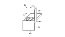
図6は、本実施の形態2にかかるケーブル接続構造を示す模式図である。図7は、図6に示すケーブル接続構造のB−B線の断面図である。図8は、本実施の形態2にかかるケーブル接続構造を示す模式図である。本実施の形態2にかかるケーブル接続構造2は、図6に示すように、基板30と、基板30に接続する複数のリード端子42(ケーブル)を有するFPC基板40と、を備えている。基板30は、例えば半導体やガラスエポキシ樹脂からなり、略矩形をなし、電気回路や、この電気回路に接続され、一方の表面に設けられる複数の電極31が形成されている。
図16は、本実施の形態3にかかるケーブル接続構造に接続される振動子モジュール100の構成を示す模式図である。図17は、本実施の形態3にかかるケーブル接続構造のFPC基板50の構成を示す模式図である。本実施の形態3で用いる振動子モジュール100は、図16に示すように、例えば圧電素子からなる角柱状の超音波振動子101が、超音波振動子101の長手方向に直交する方向に複数配列されて基板に実装されている。ここで、振動子モジュール100において、配列された複数の超音波振動子101がなす側面が弧状をなしている(コンベックス型)。各超音波振動子101は、例えば図17に示すFPC基板50と電気的に接続するための電極101aが一端側に設けられている。
3 超音波探触子
10,10a,30,30a 基板
11,41,41a,41b,51 回路形成部
12,13,31,31a,53,101a 電極
14,16,43,43a,43b,43c 延在部
15 接地電極
20,60 ケーブル
21 芯線
22 内部絶縁層
23 シールド線
24 外部絶縁層
40,40a,50 FPC基板
42,42a,52 リード端子
54 第1延在部
55 第2延在部
61 導線
100 振動子モジュール
101 超音波振動子
200 超音波内視鏡システム
210 超音波内視鏡
211 挿入部
211a 先端硬性部
211b 湾曲部
211c 可撓管部
212 操作部
212a 処置具挿入口
213 ユニバーサルケーブル
214 コネクタ部
220 内視鏡観察装置
230 超音波観測装置
240 表示装置
241 表示部
250 光源装置
260 ビデオケーブル
270 超音波ケーブル
280 光源ケーブル
Claims (2)
- 複数のケーブルと、基板に設けられた電極とを接続するケーブル接続構造であって、
前記ケーブルと一体的に設けられ、該ケーブルから延びるとともに、少なくとも前記ケーブルと前記電極との接続部分を覆う延在部を備え、
前記ケーブルは、リード端子であり、
複数の前記リード端子は、屈曲可能な絶縁性フィルムからなる基材の一端からそれぞれ突出し、
前記延在部は、屈曲可能な絶縁性フィルムからなり、前記基材に設けられ、前記リード端子の配列方向に沿って延びていることを特徴とするケーブル接続構造。 - 前記延在部は、前記基材に対して複数設けられることを特徴とする請求項1に記載のケーブル接続構造。
Priority Applications (3)
| Application Number | Priority Date | Filing Date | Title |
|---|---|---|---|
| JP2012072197A JP5973761B2 (ja) | 2012-03-27 | 2012-03-27 | ケーブル接続構造 |
| PCT/JP2013/053118 WO2013145894A1 (ja) | 2012-03-27 | 2013-02-08 | ケーブル接続構造、超音波探触子および超音波内視鏡システム |
| US14/494,980 US10158188B2 (en) | 2012-03-27 | 2014-09-24 | Cable connection structure, ultrasonic probe, and ultrasonic endoscope system |
Applications Claiming Priority (1)
| Application Number | Priority Date | Filing Date | Title |
|---|---|---|---|
| JP2012072197A JP5973761B2 (ja) | 2012-03-27 | 2012-03-27 | ケーブル接続構造 |
Related Child Applications (1)
| Application Number | Title | Priority Date | Filing Date |
|---|---|---|---|
| JP2016110338A Division JP6132963B2 (ja) | 2016-06-01 | 2016-06-01 | ケーブル接続構造、超音波探触子および超音波内視鏡システム |
Publications (3)
| Publication Number | Publication Date |
|---|---|
| JP2013206617A JP2013206617A (ja) | 2013-10-07 |
| JP2013206617A5 JP2013206617A5 (ja) | 2015-05-14 |
| JP5973761B2 true JP5973761B2 (ja) | 2016-08-23 |
Family
ID=49259178
Family Applications (1)
| Application Number | Title | Priority Date | Filing Date |
|---|---|---|---|
| JP2012072197A Active JP5973761B2 (ja) | 2012-03-27 | 2012-03-27 | ケーブル接続構造 |
Country Status (3)
| Country | Link |
|---|---|
| US (1) | US10158188B2 (ja) |
| JP (1) | JP5973761B2 (ja) |
| WO (1) | WO2013145894A1 (ja) |
Families Citing this family (9)
| Publication number | Priority date | Publication date | Assignee | Title |
|---|---|---|---|---|
| WO2018064610A1 (en) * | 2016-09-29 | 2018-04-05 | Samark Technology Llc | Video needle syringe |
| JP7013661B2 (ja) * | 2017-03-22 | 2022-02-01 | セイコーエプソン株式会社 | 超音波デバイスユニット、超音波探触子、及び超音波装置 |
| US11259831B2 (en) | 2017-09-18 | 2022-03-01 | Novuson Surgical, Inc. | Therapeutic ultrasound apparatus and method |
| WO2019146331A1 (ja) * | 2018-01-29 | 2019-08-01 | 富士フイルム株式会社 | 超音波内視鏡及び超音波内視鏡の製造方法 |
| WO2020202358A1 (ja) * | 2019-03-29 | 2020-10-08 | オリンパス株式会社 | 超音波振動子、超音波内視鏡及び超音波振動子の製造方法 |
| JP2022169817A (ja) * | 2019-09-30 | 2022-11-10 | Agc株式会社 | 高周波シールド構造 |
| US20230125441A1 (en) * | 2020-03-19 | 2023-04-27 | Sanyo Electric Co., Ltd. | Voltage detection line and voltage detection line module |
| JP7370949B2 (ja) * | 2020-09-08 | 2023-10-30 | 富士フイルム株式会社 | 超音波内視鏡 |
| WO2023233458A1 (ja) * | 2022-05-30 | 2023-12-07 | 住友電気工業株式会社 | 接続構造及び接続構造の製造方法 |
Family Cites Families (19)
| Publication number | Priority date | Publication date | Assignee | Title |
|---|---|---|---|---|
| JPS5233571Y2 (ja) * | 1972-04-28 | 1977-07-30 | ||
| JPS58116262U (ja) * | 1982-01-30 | 1983-08-08 | 日本メクトロン株式会社 | シ−ルド構造を備えたフレキシブル回路基板 |
| JPS61117265U (ja) * | 1984-12-29 | 1986-07-24 | ||
| JPS6263979U (ja) * | 1985-10-11 | 1987-04-21 | ||
| JPH077931Y2 (ja) | 1989-02-22 | 1995-03-01 | ジーイー横河メディカルシステム株式会社 | 超音波探触子 |
| JPH03151942A (ja) | 1989-11-09 | 1991-06-28 | Toshiba Corp | 超音波診断装置のメカニカルセクタプローブ |
| GB8926861D0 (en) * | 1989-11-28 | 1990-01-17 | Alcan Int Ltd | Improvements in or relating to aluminium alloys |
| JP2701563B2 (ja) * | 1991-03-18 | 1998-01-21 | 日本電気株式会社 | 表示素子の外部リード接続基板実装構造 |
| JPH05136593A (ja) | 1991-03-19 | 1993-06-01 | Fujitsu Ltd | シールド構造 |
| US5262590A (en) * | 1992-04-27 | 1993-11-16 | Sheldahl, Inc. | Impedance controlled flexible circuits with fold-over shields |
| US5375321A (en) * | 1993-03-30 | 1994-12-27 | United States Department Of Energy | Method for fabricating fan-fold shielded electrical leads |
| JP3234743B2 (ja) | 1995-05-30 | 2001-12-04 | シャープ株式会社 | 半導体部品実装型フレキシブルプリント基板 |
| JP2000067968A (ja) * | 1998-08-19 | 2000-03-03 | Tokai Rika Co Ltd | コネクタ装置及びその接続方法 |
| JP2001357916A (ja) * | 2000-06-13 | 2001-12-26 | Yazaki Corp | フラット回路体の接続構造 |
| US20020189854A1 (en) * | 2001-04-10 | 2002-12-19 | Crumly William R. | Design for long fatigue life in flexible circuits |
| JP4391717B2 (ja) * | 2002-01-09 | 2009-12-24 | 富士通マイクロエレクトロニクス株式会社 | コンタクタ及びその製造方法並びにコンタクト方法 |
| JP3885644B2 (ja) * | 2002-04-17 | 2007-02-21 | 日立電線株式会社 | 極細ケーブルの接続基板及び接続方法 |
| WO2005120130A1 (ja) * | 2004-06-03 | 2005-12-15 | Olympus Corporation | 静電容量型超音波振動子とその製造方法、静電容量型超音波プローブ |
| JP4657357B2 (ja) * | 2009-07-21 | 2011-03-23 | オリンパス株式会社 | 超音波内視鏡 |
-
2012
- 2012-03-27 JP JP2012072197A patent/JP5973761B2/ja active Active
-
2013
- 2013-02-08 WO PCT/JP2013/053118 patent/WO2013145894A1/ja active Application Filing
-
2014
- 2014-09-24 US US14/494,980 patent/US10158188B2/en active Active
Also Published As
| Publication number | Publication date |
|---|---|
| US20150011891A1 (en) | 2015-01-08 |
| WO2013145894A1 (ja) | 2013-10-03 |
| US10158188B2 (en) | 2018-12-18 |
| JP2013206617A (ja) | 2013-10-07 |
Similar Documents
| Publication | Publication Date | Title |
|---|---|---|
| JP5973761B2 (ja) | ケーブル接続構造 | |
| US10312566B2 (en) | Cable connection structure and endoscope device | |
| JP5404981B1 (ja) | 超音波内視鏡 | |
| EP2591731B1 (en) | Ultrasound transducer unit, ultrasound endoscope | |
| JP6464321B2 (ja) | 電子回路ユニット、撮像ユニットおよび内視鏡 | |
| US20180070803A1 (en) | Imaging device and endoscope system | |
| JP6351228B2 (ja) | 撮像モジュールおよび内視鏡装置 | |
| CN109414251B (zh) | 超声波内窥镜及其制造方法 | |
| US20140321244A1 (en) | Ultrasonic wave transducer using a signal pathway-integrated housing | |
| WO2017038150A1 (ja) | 内視鏡用コネクタ | |
| JP6132963B2 (ja) | ケーブル接続構造、超音波探触子および超音波内視鏡システム | |
| JP6537508B2 (ja) | ケーブル接続構造および内視鏡装置 | |
| WO2017038151A1 (ja) | 超音波プローブ | |
| JP6099541B2 (ja) | 内視鏡及び内視鏡の製造方法 | |
| US9919343B2 (en) | Ultrasound transducer and ultrasound endoscope | |
| JP7324180B2 (ja) | 超音波内視鏡 | |
| JP7395277B2 (ja) | 信号伝送配線接続ユニット、内視鏡、信号伝送配線接続ユニットの製造方法および超音波振動子モジュール | |
| JP7271790B2 (ja) | 多層基板、プローブユニット、及び超音波内視鏡 | |
| JP6033521B1 (ja) | 超音波プローブ | |
| JP2016174643A (ja) | 撮像装置 | |
| WO2017104055A1 (ja) | 撮像ユニット、内視鏡および撮像ユニットの製造方法 | |
| JP2022178902A (ja) | 内視鏡 | |
| JPWO2017150461A1 (ja) | 超音波内視鏡および超音波内視鏡の製造方法 | |
| JP2015080633A (ja) | 電気ユニット及び電気ユニットを用いた内視鏡装置 |
Legal Events
| Date | Code | Title | Description |
|---|---|---|---|
| A521 | Request for written amendment filed |
Free format text: JAPANESE INTERMEDIATE CODE: A523 Effective date: 20150325 |
|
| A621 | Written request for application examination |
Free format text: JAPANESE INTERMEDIATE CODE: A621 Effective date: 20150325 |
|
| A131 | Notification of reasons for refusal |
Free format text: JAPANESE INTERMEDIATE CODE: A131 Effective date: 20160405 |
|
| A521 | Request for written amendment filed |
Free format text: JAPANESE INTERMEDIATE CODE: A523 Effective date: 20160601 |
|
| TRDD | Decision of grant or rejection written | ||
| A01 | Written decision to grant a patent or to grant a registration (utility model) |
Free format text: JAPANESE INTERMEDIATE CODE: A01 Effective date: 20160621 |
|
| A61 | First payment of annual fees (during grant procedure) |
Free format text: JAPANESE INTERMEDIATE CODE: A61 Effective date: 20160715 |
|
| R151 | Written notification of patent or utility model registration |
Ref document number: 5973761 Country of ref document: JP Free format text: JAPANESE INTERMEDIATE CODE: R151 |
|
| R250 | Receipt of annual fees |
Free format text: JAPANESE INTERMEDIATE CODE: R250 |
|
| R250 | Receipt of annual fees |
Free format text: JAPANESE INTERMEDIATE CODE: R250 |
|
| R250 | Receipt of annual fees |
Free format text: JAPANESE INTERMEDIATE CODE: R250 |
|
| R250 | Receipt of annual fees |
Free format text: JAPANESE INTERMEDIATE CODE: R250 |
|
| R250 | Receipt of annual fees |
Free format text: JAPANESE INTERMEDIATE CODE: R250 |