JP5963873B2 - Production plan decision system - Google Patents
Production plan decision system Download PDFInfo
- Publication number
- JP5963873B2 JP5963873B2 JP2014535328A JP2014535328A JP5963873B2 JP 5963873 B2 JP5963873 B2 JP 5963873B2 JP 2014535328 A JP2014535328 A JP 2014535328A JP 2014535328 A JP2014535328 A JP 2014535328A JP 5963873 B2 JP5963873 B2 JP 5963873B2
- Authority
- JP
- Japan
- Prior art keywords
- cycle time
- component
- component mounting
- error rate
- production plan
- Prior art date
- Legal status (The legal status is an assumption and is not a legal conclusion. Google has not performed a legal analysis and makes no representation as to the accuracy of the status listed.)
- Active
Links
Images


Classifications
-
- G—PHYSICS
- G05—CONTROLLING; REGULATING
- G05B—CONTROL OR REGULATING SYSTEMS IN GENERAL; FUNCTIONAL ELEMENTS OF SUCH SYSTEMS; MONITORING OR TESTING ARRANGEMENTS FOR SUCH SYSTEMS OR ELEMENTS
- G05B19/00—Programme-control systems
- G05B19/02—Programme-control systems electric
- G05B19/418—Total factory control, i.e. centrally controlling a plurality of machines, e.g. direct or distributed numerical control [DNC], flexible manufacturing systems [FMS], integrated manufacturing systems [IMS], computer integrated manufacturing [CIM]
- G05B19/41865—Total factory control, i.e. centrally controlling a plurality of machines, e.g. direct or distributed numerical control [DNC], flexible manufacturing systems [FMS], integrated manufacturing systems [IMS], computer integrated manufacturing [CIM] characterised by job scheduling, process planning, material flow
-
- Y—GENERAL TAGGING OF NEW TECHNOLOGICAL DEVELOPMENTS; GENERAL TAGGING OF CROSS-SECTIONAL TECHNOLOGIES SPANNING OVER SEVERAL SECTIONS OF THE IPC; TECHNICAL SUBJECTS COVERED BY FORMER USPC CROSS-REFERENCE ART COLLECTIONS [XRACs] AND DIGESTS
- Y02—TECHNOLOGIES OR APPLICATIONS FOR MITIGATION OR ADAPTATION AGAINST CLIMATE CHANGE
- Y02P—CLIMATE CHANGE MITIGATION TECHNOLOGIES IN THE PRODUCTION OR PROCESSING OF GOODS
- Y02P90/00—Enabling technologies with a potential contribution to greenhouse gas [GHG] emissions mitigation
- Y02P90/02—Total factory control, e.g. smart factories, flexible manufacturing systems [FMS] or integrated manufacturing systems [IMS]
Description
本発明は、部品実装基板等を生産する生産ラインにおける生産計画を決定する技術に関するものである。 The present invention relates to a technique for determining a production plan in a production line for producing component mounting boards and the like.
電子部品等の部品を基板に実装して部品実装基板を生産する部品実装ラインは、並べて配置された複数の部品実装装置において部品実装を順次実行することで部品実装基板を生産している。この種の部品実装ラインにおける生産計画は、部品実装基板が生産されるサイクルタイムを設定された時間内に収まるように決定している。そして、従来は、いかにサイクルタイムを短縮するかについて検討を重ね、効率化を求めてきた。 2. Description of the Related Art A component mounting line that mounts components such as electronic components on a substrate to produce a component mounting substrate produces the component mounting substrate by sequentially executing component mounting in a plurality of component mounting apparatuses arranged side by side. The production plan in this type of component mounting line determines that the cycle time for producing the component mounting board is within the set time. In the past, studies have been made on how to shorten the cycle time, and efficiency has been demanded.
例えば、特許文献1には、部品実装装置に取り付けられる部品供給用の部品カセットや部品テープの配列順序を決定し、部品の実装順序を決定して、できる限り無駄な時間が発生しないようにすることでサイクルタイムの向上を実現することができる技術が提案されている。 For example, in Patent Document 1, the arrangement order of component cassettes and component tapes for supplying components to be mounted on a component mounting apparatus is determined, and the mounting order of components is determined so as not to waste time as much as possible. Thus, a technique capable of realizing improvement in cycle time has been proposed.
しかしながら、部品実装装置の前後に配置されたクリームハンダ印刷装置やリフロー炉のサイクルタイムが、部品実装装置のサイクルタイムよりも長い場合には、部品実装装置が部品実装基板製造上のボトルネックとなっていない。このため、部品実装装置におけるサイクルタイムの短縮の努力が無駄となるだけでなく、部品実装装置におけるサイクルタイムの短縮のために稼働している部品実装装置の消費電力が大きくなってしまうという問題があった。 However, if the cycle time of the cream solder printing device or the reflow furnace arranged before and after the component mounting apparatus is longer than the cycle time of the component mounting apparatus, the component mounting apparatus becomes a bottleneck in manufacturing the component mounting board. Not. For this reason, not only the effort of shortening the cycle time in the component mounting apparatus is wasted, but also the power consumption of the component mounting apparatus that is operating to shorten the cycle time in the component mounting apparatus is increased. there were.
本発明は、このような事情に鑑みてなされたものであり、部品実装装置の消費電力量を低減することができる技術を提供することを目的とする。 This invention is made | formed in view of such a situation, and it aims at providing the technique which can reduce the power consumption of a component mounting apparatus.
上述した課題を解決するためになされた、請求項1に係る発明は、複数の部品実装機によって基板に複数の部品を実装する部品実装装置における生産計画決定システムであって、各前記部品実装機のエラー率である部品実装機エラー率を取得するエラー率取得手段と、前記部品実装機エラー率に基づいて、全ての前記部品実装機のうちから1又は複数の前記部品実装機を選択する部品実装機選択処理を実行する選択手段と、前記部品実装機選択処理実行後の各前記部品実装機のサイクルタイムである部品実装機サイクルタイムを取得する部品実装機サイクルタイム取得手段と、前記部品実装装置の前工程及び後工程の少なくとも一方のサイクルタイムである装置外サイクルタイムを取得する装置外サイクルタイム取得手段と、を有し、前記選択手段は、各前記部品実装機サイクルタイムのうち最長のサイクルタイムが前記装置外サイクルタイムを超えないように、各前記部品実装機のうちから最低限の前記部品実装機を選択する。 The invention according to claim 1, which has been made to solve the above-described problem, is a production plan determination system in a component mounting apparatus that mounts a plurality of components on a board by a plurality of component mounting machines, each of the component mounting machines. An error rate acquisition means for acquiring a component mounter error rate that is an error rate of the component, and a component that selects one or more of the component mounters from all the component mounters based on the component mounter error rate Selection means for executing mounting machine selection processing; component mounting machine cycle time acquisition means for acquiring a component mounting machine cycle time that is a cycle time of each of the component mounting machines after execution of the component mounting machine selection processing; and the component mounting An external cycle time acquisition means for acquiring an external cycle time which is a cycle time of at least one of the pre-process and post-process of the apparatus, and Means, as the longest cycle time of each said component mounting machine cycle time does not exceed the device outside the cycle time, selects the minimum of the component mounter from among each said component mounting machine.
このように、選択手段は、各部品実装機サイクルタイムのうち最長のサイクルタイムが装置外サイクルタイムを超えないように、各部品実装機のうちから最低限の部品実装機を選択する。これにより、最低限の部品実装機が選択されるので、部品実装装置の消費電力量を低減することができる。また、部品実装機が選択された後の部品実装装置が部品実装ラインにおいてボトルネックとならないので、部品実装ラインの生産効率が悪化しない。 In this way, the selection means selects the minimum component mounter from among the component mounters so that the longest cycle time of each component mounter cycle time does not exceed the cycle time outside the apparatus. Thereby, since the minimum component mounting machine is selected, the power consumption of a component mounting apparatus can be reduced. In addition, since the component mounting apparatus after the component mounter is selected does not become a bottleneck in the component mounting line, the production efficiency of the component mounting line does not deteriorate.
また、稼働する部品実装機が少なくなるので、各部品実装機の各部品供給装置への部品の補給等の作業において、作業者の作業範囲が減少し、作業者の作業量を低減させることができる。 In addition, since the number of component mounters that operate is reduced, the work range of the worker is reduced in the work such as replenishment of parts to each component supply device of each component mounter, and the work amount of the worker can be reduced. it can.
選択手段が、エラー率が高い部品実装機を選択の対象から除外すると、エラー率が高い部品実装機が稼働されないので、不良品の発生を抑制することができる。また、エラー率が高い部品実装機の稼働が停止されるので、当該部品実装機をメンテナンスすることができる。 If the selection means excludes a component mounter with a high error rate from the selection targets, the component mounter with a high error rate is not operated, and therefore the occurrence of defective products can be suppressed. In addition, since the operation of the component mounter with a high error rate is stopped, the component mounter can be maintained.
請求項2に係る発明は、請求項1において、前記部品実装機選択処理を実行後の各前記部品実装機サイクルタイムのうち最長のサイクルタイムが前記装置外サイクルタイムよりも短い場合に、前記エラー率取得手段は、前記部品実装機を構成する複数の要素のエラー率である構成要素エラー率を取得し、前記選択手段は、前記構成要素エラー率に基づいて、全ての前記要素のうちから1又は複数の前記要素を選択する要素選択処理を実行し、部品実装機サイクルタイム取得手段は、前記要素選択処理実行後の各前記部品実装機のサイクルタイムである部品実装機サイクルタイムを取得し、前記選択手段は、各前記部品実装機サイクルタイムのうち最長のサイクルタイムが前記装置外サイクルタイムを超えないように、各前記要素のうちから最低限の前記要素を選択する。 According to a second aspect of the present invention, in the first aspect, when the longest cycle time among the component mounter cycle times after the execution of the component mounter selection process is shorter than the cycle time outside the apparatus, the error The rate acquisition unit acquires a component element error rate that is an error rate of a plurality of elements constituting the component mounter, and the selection unit selects one of all the elements based on the component element error rate. Or an element selection process for selecting a plurality of the elements, and the component mounter cycle time acquisition means acquires a component mounter cycle time that is a cycle time of each of the component mounters after the element selection process is executed, The selecting means selects the longest cycle time among the component mounting machines so that the longest cycle time of the component mounting machines does not exceed the cycle time outside the apparatus. Selecting the elements of the limit.
このように、選択手段は、各部品実装機サイクルタイムのうち最長のサイクルタイムが装置外サイクルタイムを超えないように、各要素のうちから最低限の要素を選択する。これにより、最低限の要素が選択されるので、部品実装装置の消費電力量を低減することができる。また、最低限の要素が選択された後の部品実装装置が部品実装ラインにおいてボトルネックとならないので、部品実装ラインの生産効率が悪化しない。 In this way, the selection means selects the minimum element from each element so that the longest cycle time of each component mounter cycle time does not exceed the cycle time outside the apparatus. Thereby, since the minimum element is selected, the power consumption of the component mounting apparatus can be reduced. In addition, since the component mounting apparatus after the minimum elements are selected does not become a bottleneck in the component mounting line, the production efficiency of the component mounting line does not deteriorate.
選択手段が、エラー率が高い要素を選択の対象から除外すると、エラー率が高い要素が稼働されないので、不良品の発生を抑制することができる。また、エラー率が高い要素の稼働が停止されるので、当該要素をメンテナンスすることができる。 If the selection unit excludes an element with a high error rate from the selection target, an element with a high error rate is not operated, so that the occurrence of defective products can be suppressed. In addition, since the operation of an element with a high error rate is stopped, the element can be maintained.
(部品実装ライン)
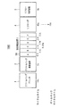
以下、本発明の実施の形態を図面に基づいて説明する。図1に示すように、部品実装ライン1000は、クリームハンダプリンタ1、クリームハンダ検査装置2、部品実装装置3、リフロー炉4、リフロー検査装置5から構成され、この順番に配置されている。図示しない搬送装置によって、基板が上述した部品実装ライン1000を構成する各装置1〜5を順次搬送される。(Component mounting line)
Hereinafter, embodiments of the present invention will be described with reference to the drawings. As shown in FIG. 1, the
クリームハンダプリンタ1は、基板にクリームハンダを印刷する装置である。クリームハンダ検査装置2は、クリームハンダプリンタ1において基板に印刷されたクリームハンダが適正に印刷されているか否かを検査する装置である。 The cream solder printer 1 is an apparatus that prints cream solder on a substrate. The cream solder inspection apparatus 2 is an apparatus that inspects whether or not the cream solder printed on the substrate in the cream solder printer 1 is properly printed.
部品実装装置3は、複数の部品実装機100A〜100Fによって構成されている。部品実装機100A〜100Fによって、順次、基板に電子部品等の部品が実装される。部品実装機100A〜100Fの具体的な構成については、後で詳細に説明する。
The component mounting apparatus 3 includes a plurality of
リフロー炉4は、クリームハンダが印刷され部品が実装された基板を加熱することにより、基板に印刷されたクリームハンダを溶融させ、当該クリームハンダで部品のリードを基板に形成されたパターンに接合するものである。 The reflow furnace 4 melts the cream solder printed on the substrate by heating the substrate on which the cream solder is printed and the component is mounted, and the lead of the component is bonded to the pattern formed on the substrate with the cream solder. Is.
リフロー検査装置5は、リフロー炉4においてリードがパターンに適正に接合されているか否かを検査する装置である。
The
(部品実装機)
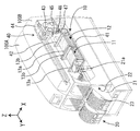
次に、図2を用いて、部品実装機100について説明する。なお、以下の説明において、基板の搬送方向をX軸方向と称し、水平面内においてX軸方向に直角な方向をY軸方向と称し、X軸方向とY軸方向とに直角な方向をZ軸方向と称する。図1に示す部品実装機100A〜100Fが、X軸方向に複数台直列に配置されて部品実装装置3(図1示)が構成されている。各部品実装機100A〜100Fは、基板搬送装置10と、部品供給装置20、及び部品装着装置40を有する。(Component mounting machine)
Next, the
部品供給装置20は、複数のスロット22と、各スロット22に着脱可能に装着される複数のフィーダ21とから構成されている。スロット22は、部品供給装置20において、X軸方向に複数直列に設けられている。フィーダ21には、リール23が着脱可能に保持されている。リール23は、多数の部品を間隔を有して一列に収容したテープ(不図示)が巻回されている。
The
フィーダ21の内部には、スプロケット(不図示)が回転可能に支承されている。スプロケットの外周部は、テープに形成された送り穴と係合する。フィーダ21には、スプロケットを回転する駆動源であるモータ(不図示)が設けられている。
A sprocket (not shown) is rotatably supported in the
リール23に巻回されたテープは、スプロケットの回転によって1ピッチずつ送り出される。すると、テープに収容された部品が、フィーダ21の先端部に設けられた部品供給位置21aに順次供給される。部品供給位置21aに供給された部品は、後述する部品装着装置40の吸着ノズル47に吸着され、基板搬送装置10によって部品実装位置に位置決めされた基板上に装着される。
The tape wound around the
基板搬送装置10は、搬送装置11,12を有している。搬送装置11,12には、部品装着装置40の基台41上に、それぞれ一対のガイドレール13a,13bが設けられている。また、搬送装置11,12は、これらガイドレール13a,13bによりそれぞれ案内される基板を支持して搬送する図略の一対のコンベアベルトが設けられている。また、基板搬送装置10には、所定位置に搬送された基板を持ち上げてクランプする図略のクランプ装置が設けられている。
The
この基板搬送装置10では、部品を実装する基板は、ガイドレール13a,13bにより案内されつつコンベアベルトによりX軸方向に部品実装位置まで搬送される。部品実装位置に搬送された基板は、クランプ装置によって部品装着位置に位置決めクランプされる。
In this
図1に示すように、部品装着装置40は、ガイドレール42、Y軸スライド43、Y軸サーボモータ44、X軸スライド45、X軸サーボモータ(不図示)、吸着ノズル47、部品装着ヘッド48を有している。
As shown in FIG. 1, the
ガイドレール42、Y軸スライド43、及びY軸サーボモータ44とから、Yロボットが構成されている。ガイドレール42は、基台41上にY方向に装架されて基板搬送装置10および部品供給装置20の上方に配設されている。Y軸スライド43は、ガイドレール42に沿ってY軸方向に移動可能に設けられている。Y軸スライド43は、Y軸サーボモータ44の出力軸に連結されたボールねじを有するボールねじ機構によってY軸方向に移動される。
The
X軸スライド45、X軸サーボモータから、Xロボットが構成されている。X軸スライド45は、Y軸スライド43に、X軸方向に移動可能に設けられている。Y軸スライド43にはX軸サーボモータが設けられている。このX軸サーボモータの出力軸に連結された図略のボールねじ機構によって、X軸スライド45がX軸方向に移動される。
An X robot is composed of the
X軸スライド45には、部品装着ヘッド48が設けられている。図8に示すように、部品装着ヘッド48は、複数の吸着ノズル47を着脱可能に保持している。吸着ノズル47は、部品を吸着する。
A
(生産計画決定システム)
次に、図3を用いて、本実施形態の生産計画決定システム500について説明する。図3に示すように、生産計画決定システム500は、CPU501、RAM502、ROMや不揮発性メモリー等で構成された記憶部503、入出力インターフェース504、報知装置506を備えている。これらは、バスを介してそれぞれ相互に接続されている。CPU501は、図4、図6、図7に示すフローチャート対応したプログラムを実行する。RAM502は同プログラムの実行に必要な変数を一時的に記憶するものである。記憶部503は上記プログラムを記憶している。(Production plan decision system)
Next, the production
入出力インターフェース504には、操作部505や報知装置506が接続されている。操作部505は、作業者が生産計画決定システム500を操作するためのものである。操作部505には、キー−ボード、マウス等のポインティングディバイス、タッチパネル等が含まれる。報知装置506は、生産計画決定システム500が決定した結果を作業者に報知させるものである。報知装置506には、ディスプレイやスピーカが含まれる。
An
入出力IF504は、クリームハンダプリンタ1、クリームハンダ検査装置2、各部品実装装機100A〜100F、リフロー炉4、リフロー検査装置5と通信可能に接続している。入出力IF504は、部品実装ライン1000を構成する各装置1〜5から後述の「サイクルタイム」を取得するとともに、各部品実装装機100A〜100Fから後述の「エラー率」を取得する。
The input / output IF 504 is communicably connected to the cream solder printer 1, the cream solder inspection device 2, the
(生産計画決定方法の概要)
基板実装ライン1000を構成する各装置1〜5に基板が搬入されてから搬出されるまでの時間を各装置1〜5の「サイクルタイム」という。各装置1〜5の「サイクルタイム」は、各装置1〜5によって異なる。(Outline of production plan determination method)
The time from when a substrate is carried into each device 1 to 5 constituting the
各部品実装機100A〜100Fの「サイクルタイム」も、各部品実装機100A〜100Fによって異なる。しかし、部品実装装置3の「サイクルタイム」は、各部品実装機100A〜100Fの「サイクルタイム」のうち最長の「サイクルタイム」となる。これは、部品実装装置3において、基板を順次部品実装機100A〜100Fに搬送するのにあたって、「サイクルタイム」が最長の部品実装機100A〜100Fがボトルネックとなるからである。
The “cycle time” of each of the
つまり、「サイクルタイム」が短い部品実装機100での基板への部品の実装が終了しても、次の部品実装機100の「サイクルタイム」が長い場合には、次の部品実装機100に基板を搬送する前に、前の次の部品実装機100において、基板の搬送を待機しなければならないからである。
That is, even if the mounting of the component on the board by the
図1に示すように、部品実装装置3の前工程であるクリームハンダプリンタ1、クリームハンダ検査装置2の「サイクルタイム」や、部品実装装置3の後工程装置であるリフロー炉4、リフロー検査装置5の「サイクルタイム」は、生産する部品実装基板の種類によらず一定であり、予め決まっている。 As shown in FIG. 1, the “cycle time” of the cream solder printer 1 and the cream solder inspection apparatus 2 that are the pre-process of the component mounting apparatus 3, the reflow furnace 4 and the reflow inspection apparatus that are the post-process apparatuses of the component mounting apparatus 3 The “cycle time” of 5 is constant regardless of the type of component mounting board to be produced, and is determined in advance.
しかし、部品実装装置3を構成する各部品実装機100A〜100Fの「サイクルタイム」は、生産する部品実装基板によって変わる。そして、部品実装機100A〜100Fのうちいずれか1以上の稼働を停止させて、部品実装基板を生産する場合には、稼働している各部品実装機100A〜100Fの「サイクルタイム」は、全ての各部品実装機100A〜100Fを稼働させた場合と比較して長くなる。
However, the “cycle time” of each of the
そして、各部品実装機100A〜100Fを構成する各「要素」(例えば吸着ノズル47)のうち1以上の稼働を停止させて部品実装基板を生産する場合には、各部品実装機100A〜100Fの「サイクルタイム」は、全ての「要素」を稼働させた場合と比較して長くなる。
When one or more of the “elements” (for example, the suction nozzle 47) constituting each
図1に示すように、部品実装ライン1000を構成する各装置のうち、部品実装装置3以外の各装置1、2、4、5の「サイクルタイム」(以下、適宜「装置外サイクルタイム」と略す)のうち最長の「サイクルタイム」(以下、適宜「ボトルネックサイクルタイム」と略す)(図1の例では、15秒)が、部品実装装置3の「サイクルタイム」(図1の例では6秒)よりも長い場合には、各部品実装機100A〜100Fのいずれか1以上の稼働を停止させても、部品実装装置3の「サイクルタイム」が「ボトルネックサイクルタイム」を超えない限り、部品実装ライン1000の生産効率が低下しない。
As shown in FIG. 1, among the devices constituting the
同様に、各部品実装機100A〜100Fを構成する各「要素」のうち1以上の稼働を停止させても、部品実装装置3の「サイクルタイム」が「ボトルネックサイクルタイム」を超えない限り、部品実装ライン1000の生産効率が低下しない。本発明は、このような知見に基づいてなされたものである。以下、詳細に説明する。
Similarly, even if one or more of the “elements” constituting each of the
(生産計画決定処理)
以下に、生産計画決定システム500が実行するプログラムである「生産計画決定処理」について、図4のフローチャートを用いて説明する。作業者が、操作部505を操作することにより、「生産計画決定処理」を開始させると、プログラムはS1に進む。(Production plan decision processing)
The “production plan determination process”, which is a program executed by the production
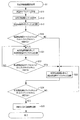
S1において、生産計画決定システム500は、稼働させる最低限の品実装機100A〜100Fを選択する「部品実装機選択処理」を実行する。この「部品実装機選択処理」については、以下に、図6に示すフローチャートを用いて説明する。
In S <b> 1, the production
「部品実装機選択処理」が開始すると、S11において、生産計画決定システム500は、各装置1、2、4、5の「装置外サイクルタイム」を取得する。S11が終了すると、プログラムはS12に進む。
When the “component mounter selection process” starts, in S11, the production
S12において、生産計画決定システム500は、各部品実装機100A〜100Fの「エラー率」を取得する。なお、この「エラー率」は、各部品実装機100A〜100Fにおける、部品吸着エラーや部品実装エラー等のエラーの総計の割合である。S12が終了すると、プログラムはS13に進む。
In S12, the production
S13において、生産計画決定システム500は、部品実装装置3の「サイクルタイム」を演算する(部品実装装置3のオプチマイズを実行する)。具体的には、生産計画決定システム500は、図5の(A)に示すように、「エラー率」が所定値より大きい部品実装機100A〜100Fを除外する。そして、生産計画決定システム500は、残りの部品実装機100A〜100Fのみが稼働したと仮定して、残りの部品実装機100A〜100Fの各「サイクルタイム」を演算する。そして、生産計画決定システム500は、上記残りの部品実装機100A〜100Fの各「サイクルタイム」のうち最長の「サイクルタイム」を部品実装装置3の「サイクルタイム」とする。S13が終了すると、プログラムは、S14に進む。
In S13, the production
S14において、生産計画決定システム500は、部品実装装置3の「サイクルタイム」が「装置外サイクルタイム」のうち最長の「サイクルタイム」である「ボトルネックサイクルタイム」を超えないと判断した場合には(S14:YES)、プログラムをS21に進め、部品実装装置3の「サイクルタイム」が「ボトルネックサイクルタイム」を超えると判断した場合には(S14:NO)、プログラムをS23に進める。
In S <b> 14, when the production
S21において、生産計画決定システム500は、前回の部品実装装置3の「サイクルタイム」演算処理に比べて、部品実装機100A〜100Fを除外するための「エラー率」を下げたうえで、当該「エラー率」が所定値より大きい部品実装機100A〜100Fを除外する。そして、生産計画決定システム500は、残りの部品実装機100A〜100Fのみが稼働したと仮定して、残りの部品実装機100A〜100Fの各「サイクルタイム」を演算する。すると、前回の部品実装装置3の「サイクルタイム」演算処理に比べて、稼働する部品実装機100A〜100Fの数が減るので、上記残りの部品実装機100A〜100Fの各「サイクルタイム」が長くなる。この結果、部品実装装置3の「サイクルタイム」が長くなる。S21が終了すると、プログラムはS22に進む。
In S <b> 21, the production
S22において、生産計画決定システム500は、部品実装装置3の「サイクルタイム」が「ボトルネックサイクルタイム」を超えると判断した場合には(S22:YES)、プログラムをS23に進め、部品実装装置3の「サイクルタイム」が「ボトルネックサイクルタイム」を超えないと判断した場合には(S22:NO)、プログラムをS21に戻す。
In S22, when the production
S23において、図5の(B)に示すように、生産計画決定システム500は、前回の部品実装装置3の「サイクルタイム」演算処理に比べて、部品実装機100A〜100Fを除外するための「エラー率」を上げたうえで、当該「エラー率」が所定値より大きい部品実装機100A〜100Fを除外する。そして、生産計画決定システム500は、残りの部品実装機100A〜100Fのみが稼働したと仮定して、残りの部品実装機100A〜100Fの各「サイクルタイム」を演算する。すると、前回の部品実装装置3の「サイクルタイム」演算処理に比べて、稼働する部品実装機100A〜100Fが増えるので、上記残りの部品実装機100A〜100Fの各「サイクルタイム」が短くなる。この結果、部品実装装置3の「サイクルタイム」が短くなる。S23が終了すると、プログラムはS24に進む。
In S <b> 23, as shown in FIG. 5B, the production
S24において、生産計画決定システム500は、部品実装装置3の「サイクルタイム」が「ボトルネックサイクルタイム」を超えないと判断した場合には(S24:YES)、プログラムをS25に進め、部品実装装置3の「サイクルタイム」が「ボトルネックサイクルタイム」を超えると判断した場合には(S24:NO)、プログラムをS23に戻す。
In S24, if the production
S25において、生産計画決定システム500は、S24でYESと判断された部品実装機100A〜100Fの組み合わせを、稼働させる最低限の部品実装機100A〜100Fとして選択し、記憶部503に記憶させる。S25が終了すると、「部品実装機選択処理」が終了し、プログラムは、図4のS2に進む。
In S25, the production
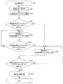
S2において、生産計画決定システム500は、S1において選択された部品実装機100A〜100Fについて、稼働させる最低限の「要素」を選択する「要素選択処理」を実行する。この「要素選択処理」については、図7に示すフローチャートを用いて説明する。
In S2, the production
「要素選択処理」が開始すると、S52において、生産計画決定システム500は、各部品実装機100A〜100Fを構成する各「要素」の「エラー率」を取得する。なお、本実施形態では、図8に示すように、上記「要素」は、吸着ノズル47であり、上記「エラー率」は、吸着ノズル47での吸着エラーの率である。S52が終了すると、プログラムはS53に進む。
When the “element selection process” starts, in S52, the production
S53において、生産計画決定システム500は、部品実装装置3の「サイクルタイム」を演算する。具体的には、生産計画決定システム500は、図8の(A)に示すように、「エラー率」が所定値より大きい吸着ノズル47を除外して、残りの吸着ノズル47を稼働させた場合における図6のS25で選択された各部品実装機100A〜100Fの各「サイクルタイム」を演算する。なお、基板に部品を実装するのに、稼働させる吸着ノズル47を減らすと、各部品実装機100A〜100Fの「サイクルタイム」が長くなる。そして、生産計画決定システム500は、上記残りの部品実装機100A〜100Fの各「サイクルタイム」のうち最長の「サイクルタイム」を部品実装装置3の「サイクルタイム」とする。S53が終了すると、プログラムは、S54に進む。
In S53, the production
S54において、生産計画決定システム500は、部品実装装置3の「サイクルタイム」が「ボトルネックサイクルタイム」を超えないと判断した場合には(S54:YES)、プログラムをS61に進め、部品実装装置3の「サイクルタイム」が「ボトルネックサイクルタイム」を超えると判断した場合には(S54:NO)、プログラムをS63に進める。
In S54, if the production
S61において、生産計画決定システム500は、前回の部品実装装置3の「サイクルタイム」演算処理に比べて、吸着ノズル47を除外するための「エラー率」を下げたうえで、当該「エラー率」が所定値より大きい吸着ノズル47を除外する。そして、生産計画決定システム500は、残りの吸着ノズル47を稼働させた場合における図6のS25で選択された各部品実装機100A〜100Fの各「サイクルタイム」を演算する。すると、前回の部品実装装置3の「サイクルタイム」演算処理に比べて、稼働する吸着ノズル47の数が減るので、上記部品実装機100A〜100Fの各「サイクルタイム」が長くなる。この結果、部品実装装置3の「サイクルタイム」が長くなる。S61が終了すると、プログラムはS62に進む。
In S <b> 61, the production
S62において、生産計画決定システム500は、部品実装装置3の「サイクルタイム」が「ボトルネックサイクルタイム」を超えると判断した場合には(S62:YES)、プログラムをS63に進め、部品実装装置3の「サイクルタイム」が「ボトルネックサイクルタイム」を超えない判断した場合には(S62:NO)、プログラムをS61に戻す。
In S62, when the production
S63において、図8の(B)に示すように、生産計画決定システム500は、前回の部品実装装置3の「サイクルタイム」演算処理に比べて、吸着ノズル47を除外するための「エラー率」を上げたうえで、当該「エラー率」が所定値より大きい吸着ノズル47を除外する。そして、生産計画決定システム500は、残りの吸着ノズル47を稼働させた場合における図6のS25で選択された各部品実装機100A〜100Fの各「サイクルタイム」を演算する。すると、前回の部品実装装置3の「サイクルタイム」演算処理に比べて、稼働する吸着ノズル47が増えるので、上記部品実装機100A〜100Fの各「サイクルタイム」が短くなる。この結果、部品実装装置3の「サイクルタイム」が短くなる。S63が終了すると、プログラムはS64に進む。
In S <b> 63, as shown in FIG. 8B, the production
S65において、生産計画決定システム500は、S64でYESと判断された吸着ノズル47の組み合わせを、稼働させる最低限の吸着ノズル47として選択し、記憶部503に記憶させる。S65が終了すると、「要素選択処理」が終了し、図4のS3に進む。
In S <b> 65, the production
S3において、生産計画決定システム500は、S1で選択された選択された部品実装機100A〜100F及びS2で選択された吸着ノズル47を、報知装置506で報知する。S3が終了すると、「生産計画決定処理」が終了する。
In S <b> 3, the production
このように、「生産計画決定処理」が実行されると、「ボトルネックサイクルタイム」を超えないように、最低限の部品実装機100A〜100Fが選択され、更に選択された各部品実装機100A〜100Fにおいて最低限の吸着ノズル47が選択される。
As described above, when the “production plan determination process” is executed, the
(本実施形態の効果)
以上の説明から明らかなように、生産計画決定システム500(選択手段)は、図6に示す「部品実装機選択処理」を実行することにより、各部品実装機100A〜100Fの「サイクルタイム」のうち最長の「サイクルタイム」である部品実装装置3の「サイクルタイム」が、「装置外サイクルタイム」のうち最長の「ボトルネックサイクルタイム」を超えないように、各部品実機100A〜100Fのうちから最低限の部品実装機100A〜100Fを選択する。これにより、稼働させる最低限の部品実装機100A〜100Fが選択されるので、部品実装装置3の消費電力量を低減することができる。また、部品実装機100A〜100Fが選択された後の部品実装装置3が部品実装ライン1000においてボトルネックとならず、部品実装ライン1000の生産効率が悪化しない。(Effect of this embodiment)
As is clear from the above description, the production plan determination system 500 (selecting means) executes the “component mounter selection process” shown in FIG. 6 to determine the “cycle time” of each of the
また、稼働する部品実装機100A〜100Fが少なくなるので、各部品実装機100A〜100Fの各部品供給装置20への部品の補給等の作業において、作業者の作業範囲が減少し、作業者の作業量を低減させることができる。
In addition, since the number of
また、生産計画決定システム500は、「エラー率」が高い部品実装機100A〜100Fを選択の対象から除外しているので、「エラー率」が高い部品実装機100A〜100Fが稼働されないので、不良品の発生を抑制することができる。また、「エラー率」が高い部品実装機100A〜100Fの稼働が停止されるので、当該部品実装機100A〜100Fをメンテナンスすることができる。
In addition, since the production
また、生産計画決定システム500は、図7に示す「要素選択処理」において、部品実装装置3の「サイクルタイム」が「ボトルネックサイクルタイム」を超えないように、各吸着ノズル47(要素)のうちから最低限の吸着ノズル47を選択する。これにより、最低限の吸着ノズル47が選択されるので、部品実装装置3の消費電力量を低減することができる。また、最低限の吸着ノズル47が選択された後の部品実装装置3が部品実装ライン1000においてボトルネックとならないので、部品実装ライン1000の生産効率が悪化しない。
Further, the production
また、生産計画決定システム500は、エラー率が高い吸着ノズル47を選択の対象から除外しているので、「エラー率」が高い吸着ノズル47が稼働されないので、不良品の発生を抑制することができる。また、「エラー率」が高い吸着ノズル47の稼働が停止されるので、当該吸着ノズル47をメンテナンスすることができる。
In addition, since the production
(他の実施形態)
以上説明した実施形態では、生産計画決定システム500は、入出力インターフェース504を介して、「装置外サイクルタイム」、各部品実装機100A〜100Fの「サイクルタイム」、各部品実装機100A〜100Fの「エラー率」、各吸着ノズル47の「エラー率」を取得している。しかし、作業者が、操作部505を操作することにより、「装置外サイクルタイム」、各部品実装機100A〜100Fの「サイクルタイム」、各部品実装機100A〜100Fの「エラー率」、各吸着ノズル47の「エラー率」を生産計画決定システム500に入力する実施形態で有っても差し支え無い。この実施形態の場合には、入出力インターフェース504は、各装置1〜5と通信可能に接続されていなくても差し支え無い。(Other embodiments)
In the embodiment described above, the production
以上説明した実施形態では、図7に示す「要素選択処理」において、選択される「要素」は吸着ノズル47である。しかし、選択される「要素」はこれに限定されず、例えば、フィーダ21や、搬送装置11,12、部品装着ヘッド48等であっても差し支え無く、このような実施形態にも本実施形態の技術的思想が適用可能なことは言うまでもない。
In the embodiment described above, the “element” selected in the “element selection process” shown in FIG. However, the “element” to be selected is not limited to this, and may be, for example, the
以上説明した実施形態では、部品実装ライン1000は、部品実装装置3の前工程の装置1、2及び部品実装装置3の後工程の装置4、5を有している。しかし、部品実装ライン1000が、部品実装装置3の前工程の装置1、2及び部品実装装置3の後工程の装置4、5のいずれか一方のみを有している実施形態で有っても差し支え無い。
In the embodiment described above, the
1…クリームハンダプリンタ(前工程装置)、2…クリームハンダ検査装置(前工程装置)、3…部品実装装置、4…リフロー炉(後工程装置)、5…リフロー検査装置(後工程装置)、11…搬送装置(要素)、12…搬送装置(要素)、20…部品供給装置(要素)、47…吸着ノズル(要素)、48…部品装着ヘッド(要素)、100A〜100F…部品実装機、500…生産計画決定システム(選択手段、部品実装機サイクルタイム取得手段、装置外サイクルタイム取得手段)、1000…部品実装ライン
DESCRIPTION OF SYMBOLS 1 ... Cream solder printer (pre-process apparatus), 2 ... Cream solder inspection apparatus (pre-process apparatus), 3 ... Component mounting apparatus, 4 ... Reflow furnace (post process apparatus), 5 ... Reflow inspection apparatus (post process apparatus), DESCRIPTION OF
Claims (2)
各前記部品実装機のエラー率である部品実装機エラー率を取得するエラー率取得手段と、
前記部品実装機エラー率に基づいて、全ての前記部品実装機のうちから1又は複数の前記部品実装機を選択する部品実装機選択処理を実行する選択手段と、
前記部品実装機選択処理実行後の各前記部品実装機のサイクルタイムである部品実装機サイクルタイムを取得する部品実装機サイクルタイム取得手段と、
前記部品実装装置の前工程及び後工程の少なくとも一方のサイクルタイムである装置外サイクルタイムを取得する装置外サイクルタイム取得手段と、を有し、
前記選択手段は、各前記部品実装機サイクルタイムのうち最長のサイクルタイムが前記装置外サイクルタイムを超えないように、各前記部品実装機のうちから最低限の前記部品実装機を選択する生産計画決定システム。A production plan determination system in a component mounting apparatus that mounts a plurality of components on a substrate by a plurality of component mounting machines,
Error rate acquisition means for acquiring a component mounter error rate that is an error rate of each of the component mounters;
A selection means for executing a component mounter selection process for selecting one or a plurality of the component mounters from all the component mounters based on the component mounter error rate;
Component mounter cycle time acquisition means for acquiring a component mounter cycle time that is a cycle time of each of the component mounters after the component mounter selection process is executed,
An external cycle time acquisition means for acquiring an external cycle time which is a cycle time of at least one of a pre-process and a post-process of the component mounting apparatus;
The selection means selects a minimum of the component mounters from the component mounters so that the longest cycle time of the component mounter cycle times does not exceed the cycle time outside the apparatus. Decision system.
前記部品実装機選択処理を実行後の各前記部品実装機サイクルタイムのうち最長のサイクルタイムが前記装置外サイクルタイムよりも短い場合に、
前記エラー率取得手段は、前記部品実装機を構成する複数の要素のエラー率である構成要素エラー率を取得し、
前記選択手段は、前記構成要素エラー率に基づいて、全ての前記要素のうちから1又は複数の前記要素を選択する要素選択処理を実行し、
部品実装機サイクルタイム取得手段は、前記要素選択処理実行後の各前記部品実装機のサイクルタイムである部品実装機サイクルタイムを取得し、
前記選択手段は、各前記部品実装機サイクルタイムのうち最長のサイクルタイムが前記装置外サイクルタイムを超えないように、各前記要素のうちから最低限の前記要素を選択する生産計画決定システム。In claim 1,
When the longest cycle time of each of the component mounter cycle times after executing the component mounter selection process is shorter than the cycle time outside the apparatus,
The error rate acquisition means acquires a component element error rate, which is an error rate of a plurality of elements constituting the component mounter,
The selection means performs an element selection process for selecting one or a plurality of the elements from all the elements based on the component error rate,
The component mounter cycle time acquisition means acquires a component mounter cycle time that is a cycle time of each of the component mounters after the element selection process is executed,
The said selection means is the production plan determination system which selects the said minimum element from each said element so that the longest cycle time among each said component mounting machine cycle time may not exceed the said apparatus outside cycle time.
Applications Claiming Priority (1)
| Application Number | Priority Date | Filing Date | Title |
|---|---|---|---|
| PCT/JP2012/073684 WO2014041686A1 (en) | 2012-09-14 | 2012-09-14 | System for determining production schedule |
Publications (2)
| Publication Number | Publication Date |
|---|---|
| JP5963873B2 true JP5963873B2 (en) | 2016-08-03 |
| JPWO2014041686A1 JPWO2014041686A1 (en) | 2016-08-12 |
Family
ID=50277838
Family Applications (1)
| Application Number | Title | Priority Date | Filing Date |
|---|---|---|---|
| JP2014535328A Active JP5963873B2 (en) | 2012-09-14 | 2012-09-14 | Production plan decision system |
Country Status (2)
| Country | Link |
|---|---|
| JP (1) | JP5963873B2 (en) |
| WO (1) | WO2014041686A1 (en) |
Cited By (1)
| Publication number | Priority date | Publication date | Assignee | Title |
|---|---|---|---|---|
| EP4228385A1 (en) * | 2022-02-09 | 2023-08-16 | Siemens Aktiengesellschaft | Computer-implemented method for determining an optimal allocation of component types to an assembly line selected with regard to its loading performance |
Families Citing this family (5)
| Publication number | Priority date | Publication date | Assignee | Title |
|---|---|---|---|---|
| JP6491317B2 (en) * | 2015-03-26 | 2019-03-27 | 株式会社Fuji | Component mounting line optimization apparatus and component mounting line optimization method |
| JP6457449B2 (en) | 2016-09-05 | 2019-01-23 | ファナック株式会社 | Numerical control device, control system, control method, and control program |
| JP6926472B2 (en) * | 2016-12-27 | 2021-08-25 | 株式会社ジェイテクト | Analytical equipment and analysis system |
| JP6659652B2 (en) | 2017-10-31 | 2020-03-04 | ファナック株式会社 | Processing condition adjustment device and machine learning device |
| JP2022103968A (en) * | 2020-12-28 | 2022-07-08 | 東京ロボティクス株式会社 | Operation schedule generating device, method, program, and system |
Family Cites Families (3)
| Publication number | Priority date | Publication date | Assignee | Title |
|---|---|---|---|---|
| JP3611360B2 (en) * | 1995-02-28 | 2005-01-19 | 松下電器産業株式会社 | Component mounting method and destination integrated operation data creation device |
| JP3466141B2 (en) * | 2000-08-04 | 2003-11-10 | 松下電器産業株式会社 | Component mounting order optimization method, device therefor, and component mounting device |
| JP5641888B2 (en) * | 2010-11-10 | 2014-12-17 | 富士機械製造株式会社 | Component verification method and component mounting system |
-
2012
- 2012-09-14 WO PCT/JP2012/073684 patent/WO2014041686A1/en active Application Filing
- 2012-09-14 JP JP2014535328A patent/JP5963873B2/en active Active
Cited By (1)
| Publication number | Priority date | Publication date | Assignee | Title |
|---|---|---|---|---|
| EP4228385A1 (en) * | 2022-02-09 | 2023-08-16 | Siemens Aktiengesellschaft | Computer-implemented method for determining an optimal allocation of component types to an assembly line selected with regard to its loading performance |
Also Published As
| Publication number | Publication date |
|---|---|
| WO2014041686A1 (en) | 2014-03-20 |
| JPWO2014041686A1 (en) | 2016-08-12 |
Similar Documents
| Publication | Publication Date | Title |
|---|---|---|
| JP5963873B2 (en) | Production plan decision system | |
| WO2016142988A1 (en) | Method for optimizing arrangement of part types, and device for optimizing arrangement of part types | |
| JP4945390B2 (en) | Production management device | |
| CN110268814B (en) | Production management device | |
| JP6075932B2 (en) | Substrate inspection management method and apparatus | |
| JP2013073998A (en) | Substrate transfer device, substrate transfer method and surface mounting machine | |
| JP5980944B2 (en) | Production monitoring system and production monitoring method for component mounting line | |
| US20150223370A1 (en) | Work system for substrates and working machine | |
| JPWO2004064473A1 (en) | Substrate carrying-in method in mounting line, substrate production system, and substrate production method in substrate production system | |
| EP2897449B1 (en) | Work system for substrate and workbench-quantity-determining program | |
| JP5651667B2 (en) | Substrate transport device, substrate working device, and transport belt | |
| JP6526808B2 (en) | Mounting management device | |
| JP6806890B2 (en) | Production control equipment | |
| JP4494910B2 (en) | Surface mount equipment | |
| JP5697438B2 (en) | Mounting system | |
| JP5762239B2 (en) | Substrate processing system, substrate supply order determination method, program, recording medium | |
| JP6963021B2 (en) | Board work system | |
| JP2006287047A (en) | Substrate recognizing method and component mounting system | |
| JP7026845B2 (en) | Servo amplifier system | |
| WO2023021549A1 (en) | Production program generation method | |
| JP7319448B2 (en) | Mounting machine | |
| JP7117058B2 (en) | Part type placement calculation device | |
| WO2023139644A1 (en) | Work machine system | |
| JP6535698B2 (en) | Board work method, work procedure optimization program | |
| JP2018037594A (en) | Component type arrangement method and component type arrangement arithmetic unit |
Legal Events
| Date | Code | Title | Description |
|---|---|---|---|
| TRDD | Decision of grant or rejection written | ||
| A01 | Written decision to grant a patent or to grant a registration (utility model) |
Free format text: JAPANESE INTERMEDIATE CODE: A01 Effective date: 20160607 |
|
| A61 | First payment of annual fees (during grant procedure) |
Free format text: JAPANESE INTERMEDIATE CODE: A61 Effective date: 20160628 |
|
| R150 | Certificate of patent or registration of utility model |
Ref document number: 5963873 Country of ref document: JP Free format text: JAPANESE INTERMEDIATE CODE: R150 |
|
| S533 | Written request for registration of change of name |
Free format text: JAPANESE INTERMEDIATE CODE: R313533 |
|
| R350 | Written notification of registration of transfer |
Free format text: JAPANESE INTERMEDIATE CODE: R350 |
|
| R250 | Receipt of annual fees |
Free format text: JAPANESE INTERMEDIATE CODE: R250 |
|
| R250 | Receipt of annual fees |
Free format text: JAPANESE INTERMEDIATE CODE: R250 |
|
| R250 | Receipt of annual fees |
Free format text: JAPANESE INTERMEDIATE CODE: R250 |
|
| R250 | Receipt of annual fees |
Free format text: JAPANESE INTERMEDIATE CODE: R250 |
|
| R250 | Receipt of annual fees |
Free format text: JAPANESE INTERMEDIATE CODE: R250 |