JP5937967B2 - Friction stir welding equipment - Google Patents
Friction stir welding equipment Download PDFInfo
- Publication number
- JP5937967B2 JP5937967B2 JP2012541907A JP2012541907A JP5937967B2 JP 5937967 B2 JP5937967 B2 JP 5937967B2 JP 2012541907 A JP2012541907 A JP 2012541907A JP 2012541907 A JP2012541907 A JP 2012541907A JP 5937967 B2 JP5937967 B2 JP 5937967B2
- Authority
- JP
- Japan
- Prior art keywords
- friction stir
- stir welding
- joining
- linear guide
- tool
- Prior art date
- Legal status (The legal status is an assumption and is not a legal conclusion. Google has not performed a legal analysis and makes no representation as to the accuracy of the status listed.)
- Expired - Fee Related
Links
Images


Classifications
-
- B—PERFORMING OPERATIONS; TRANSPORTING
- B23—MACHINE TOOLS; METAL-WORKING NOT OTHERWISE PROVIDED FOR
- B23K—SOLDERING OR UNSOLDERING; WELDING; CLADDING OR PLATING BY SOLDERING OR WELDING; CUTTING BY APPLYING HEAT LOCALLY, e.g. FLAME CUTTING; WORKING BY LASER BEAM
- B23K20/00—Non-electric welding by applying impact or other pressure, with or without the application of heat, e.g. cladding or plating
- B23K20/12—Non-electric welding by applying impact or other pressure, with or without the application of heat, e.g. cladding or plating the heat being generated by friction; Friction welding
- B23K20/122—Non-electric welding by applying impact or other pressure, with or without the application of heat, e.g. cladding or plating the heat being generated by friction; Friction welding using a non-consumable tool, e.g. friction stir welding
- B23K20/1245—Non-electric welding by applying impact or other pressure, with or without the application of heat, e.g. cladding or plating the heat being generated by friction; Friction welding using a non-consumable tool, e.g. friction stir welding characterised by the apparatus
-
- B—PERFORMING OPERATIONS; TRANSPORTING
- B23—MACHINE TOOLS; METAL-WORKING NOT OTHERWISE PROVIDED FOR
- B23K—SOLDERING OR UNSOLDERING; WELDING; CLADDING OR PLATING BY SOLDERING OR WELDING; CUTTING BY APPLYING HEAT LOCALLY, e.g. FLAME CUTTING; WORKING BY LASER BEAM
- B23K20/00—Non-electric welding by applying impact or other pressure, with or without the application of heat, e.g. cladding or plating
- B23K20/12—Non-electric welding by applying impact or other pressure, with or without the application of heat, e.g. cladding or plating the heat being generated by friction; Friction welding
- B23K20/1205—Non-electric welding by applying impact or other pressure, with or without the application of heat, e.g. cladding or plating the heat being generated by friction; Friction welding using translation movement
-
- B—PERFORMING OPERATIONS; TRANSPORTING
- B23—MACHINE TOOLS; METAL-WORKING NOT OTHERWISE PROVIDED FOR
- B23K—SOLDERING OR UNSOLDERING; WELDING; CLADDING OR PLATING BY SOLDERING OR WELDING; CUTTING BY APPLYING HEAT LOCALLY, e.g. FLAME CUTTING; WORKING BY LASER BEAM
- B23K20/00—Non-electric welding by applying impact or other pressure, with or without the application of heat, e.g. cladding or plating
- B23K20/12—Non-electric welding by applying impact or other pressure, with or without the application of heat, e.g. cladding or plating the heat being generated by friction; Friction welding
- B23K20/122—Non-electric welding by applying impact or other pressure, with or without the application of heat, e.g. cladding or plating the heat being generated by friction; Friction welding using a non-consumable tool, e.g. friction stir welding
- B23K20/1225—Particular aspects of welding with a non-consumable tool
-
- B—PERFORMING OPERATIONS; TRANSPORTING
- B23—MACHINE TOOLS; METAL-WORKING NOT OTHERWISE PROVIDED FOR
- B23K—SOLDERING OR UNSOLDERING; WELDING; CLADDING OR PLATING BY SOLDERING OR WELDING; CUTTING BY APPLYING HEAT LOCALLY, e.g. FLAME CUTTING; WORKING BY LASER BEAM
- B23K20/00—Non-electric welding by applying impact or other pressure, with or without the application of heat, e.g. cladding or plating
- B23K20/12—Non-electric welding by applying impact or other pressure, with or without the application of heat, e.g. cladding or plating the heat being generated by friction; Friction welding
- B23K20/122—Non-electric welding by applying impact or other pressure, with or without the application of heat, e.g. cladding or plating the heat being generated by friction; Friction welding using a non-consumable tool, e.g. friction stir welding
- B23K20/123—Controlling or monitoring the welding process
-
- B—PERFORMING OPERATIONS; TRANSPORTING
- B23—MACHINE TOOLS; METAL-WORKING NOT OTHERWISE PROVIDED FOR
- B23K—SOLDERING OR UNSOLDERING; WELDING; CLADDING OR PLATING BY SOLDERING OR WELDING; CUTTING BY APPLYING HEAT LOCALLY, e.g. FLAME CUTTING; WORKING BY LASER BEAM
- B23K20/00—Non-electric welding by applying impact or other pressure, with or without the application of heat, e.g. cladding or plating
- B23K20/12—Non-electric welding by applying impact or other pressure, with or without the application of heat, e.g. cladding or plating the heat being generated by friction; Friction welding
- B23K20/122—Non-electric welding by applying impact or other pressure, with or without the application of heat, e.g. cladding or plating the heat being generated by friction; Friction welding using a non-consumable tool, e.g. friction stir welding
- B23K20/1245—Non-electric welding by applying impact or other pressure, with or without the application of heat, e.g. cladding or plating the heat being generated by friction; Friction welding using a non-consumable tool, e.g. friction stir welding characterised by the apparatus
- B23K20/125—Rotary tool drive mechanism
-
- B—PERFORMING OPERATIONS; TRANSPORTING
- B23—MACHINE TOOLS; METAL-WORKING NOT OTHERWISE PROVIDED FOR
- B23K—SOLDERING OR UNSOLDERING; WELDING; CLADDING OR PLATING BY SOLDERING OR WELDING; CUTTING BY APPLYING HEAT LOCALLY, e.g. FLAME CUTTING; WORKING BY LASER BEAM
- B23K20/00—Non-electric welding by applying impact or other pressure, with or without the application of heat, e.g. cladding or plating
- B23K20/12—Non-electric welding by applying impact or other pressure, with or without the application of heat, e.g. cladding or plating the heat being generated by friction; Friction welding
- B23K20/122—Non-electric welding by applying impact or other pressure, with or without the application of heat, e.g. cladding or plating the heat being generated by friction; Friction welding using a non-consumable tool, e.g. friction stir welding
- B23K20/1245—Non-electric welding by applying impact or other pressure, with or without the application of heat, e.g. cladding or plating the heat being generated by friction; Friction welding using a non-consumable tool, e.g. friction stir welding characterised by the apparatus
- B23K20/126—Workpiece support, i.e. backing or clamping
-
- B—PERFORMING OPERATIONS; TRANSPORTING
- B23—MACHINE TOOLS; METAL-WORKING NOT OTHERWISE PROVIDED FOR
- B23K—SOLDERING OR UNSOLDERING; WELDING; CLADDING OR PLATING BY SOLDERING OR WELDING; CUTTING BY APPLYING HEAT LOCALLY, e.g. FLAME CUTTING; WORKING BY LASER BEAM
- B23K20/00—Non-electric welding by applying impact or other pressure, with or without the application of heat, e.g. cladding or plating
- B23K20/12—Non-electric welding by applying impact or other pressure, with or without the application of heat, e.g. cladding or plating the heat being generated by friction; Friction welding
- B23K20/1285—Portable friction welding machines
-
- B—PERFORMING OPERATIONS; TRANSPORTING
- B23—MACHINE TOOLS; METAL-WORKING NOT OTHERWISE PROVIDED FOR
- B23K—SOLDERING OR UNSOLDERING; WELDING; CLADDING OR PLATING BY SOLDERING OR WELDING; CUTTING BY APPLYING HEAT LOCALLY, e.g. FLAME CUTTING; WORKING BY LASER BEAM
- B23K37/00—Auxiliary devices or processes, not specially adapted to a procedure covered by only one of the preceding main groups
- B23K37/04—Auxiliary devices or processes, not specially adapted to a procedure covered by only one of the preceding main groups for holding or positioning work
- B23K37/0461—Welding tables
Description
本発明は、ワークを摩擦撹拌接合するために用いられる摩擦撹拌接合装置に関する。
本願は、2010年11月4日に日本に出願された特願2010−247811号に基づき優先権を主張し、その内容をここに援用する。The present invention relates to a friction stir welding apparatus used for friction stir welding of workpieces.
This application claims priority based on Japanese Patent Application No. 2010-247811 for which it applied to Japan on November 4, 2010, and uses the content here.
摩擦撹拌接合では、摩擦撹拌接合用ツールの先端部に設けられたプローブ(棒状突起物)を、ワークの接合部に回転させながら押し付けてワーク内に没入させることにより、ワークの接合部に摩擦熱を発生させて、ワークを軟化させると共に、上記摩擦撹拌接合用ツールの回転力により、接合部周辺を塑性流動させて撹拌混合し、複数のワークを一体に接合する。摩擦撹拌接合は、現在、接合時に生じる接合反力が小さいアルミ材薄板(厚さ10mm以下)の接合を中心に利用されつつある。 In friction stir welding, the probe (rod-like projection) provided at the tip of the friction stir welding tool is pressed against the workpiece joint while rotating and immersed in the workpiece, so that frictional heat is applied to the workpiece joint. Is generated, and the work is softened, and the periphery of the joint is plastically flowed by the rotational force of the friction stir welding tool to stir and mix, thereby joining a plurality of works integrally. Friction stir welding is currently being used mainly for joining aluminum thin plates (thickness of 10 mm or less) with a small joining reaction force generated during joining.
摩擦撹拌接合に用いる従来の摩擦撹拌接合装置としては、ワークを載置する定盤の両側に設置した案内レールと、上記定盤を跨いで上記案内レール上に移動自在に設置した門型フレームと、門型フレームに定盤の幅方向に移動自在に片持ち支持させた基台と、基台に上下方向に移動自在に片持ち支持させた接合装置本体と、接合装置本体の下端部に回転可能に取り付けた摩擦撹拌接合用ツールとを備える装置が提案されている(たとえば特許文献1参照)。 As a conventional friction stir welding apparatus used for friction stir welding, there are a guide rail installed on both sides of a surface plate on which a work is placed, and a portal frame that is movably installed on the guide rail across the surface plate. , A base that is cantilevered and supported by the portal frame in the width direction of the surface plate, a joining device body that is cantilevered and supported by the base so that it can move in the vertical direction, and a lower end of the joining device body. An apparatus provided with a friction stir welding tool that can be attached has been proposed (see, for example, Patent Document 1).
また、従来の摩擦撹拌接合装置の他の例としては、摩擦撹拌接合用ツールと摩擦撹拌接合用ツールを回転駆動する回転駆動手段と上記摩擦撹拌接合用ツールを上下方向に移動させる変位駆動手段とを備えてなる接合装置本体を、車輪と車輪を回転駆動させる車輪回転手段とを備えて自走可能な車体に搭載した装置が提案されている(たとえば特許文献2参照)。 In addition, as another example of the conventional friction stir welding apparatus, a friction stir welding tool, a rotation driving unit that rotationally drives the friction stir welding tool, and a displacement driving unit that moves the friction stir welding tool up and down. There has been proposed a device in which a main body of a joining device including a wheel and a wheel rotation means for rotating the wheel is mounted on a self-propelled vehicle body (see, for example, Patent Document 2).
ところが、上記特許文献1に記載されたような、接合装置本体を片持ち支持する構造を有する摩擦撹拌接合装置では、摩擦撹拌接合時に生じる接合反力が大きい場合、たとえば、厚板(たとえば、アルミ材では18mm以上)同士の接合等に際して接合反力が約1tを超える場合などでは、その大きな接合反力を受けることができず、正常にワークの摩擦撹拌接合を行うことができない。また、門型フレームがワークを跨ぐ構造であるため、摩擦撹拌接合することができるワークのサイズ(幅寸法)が門型フレームの大きさに制限され、ワークサイズが大きい場合は装置を大型化しなければならない。
However, in the friction stir welding apparatus having a structure in which the joining apparatus main body is cantilevered as described in
また、上記特許文献2に記載されたような、車輪を用いて自走可能にした摩擦撹拌接合装置では、摩擦撹拌接合時に生じる接合反力が大きい場合、その接合反力により走行方向がぶれてしまい、正常にワークの摩擦撹拌接合を行うことができない。なお、上記特許文献2では、摩擦撹拌接合装置の一方の側にワーク間の接合線に沿って延びるガイド部材を設置すると共に、ガイド部材を挟持する一対のローラとローラを回転自在に支持する固定部とを備えるガイド機構を摩擦撹拌接合装置に設けて、ガイド部材に沿って摩擦撹拌接合装置を移動させる構造も提案されているが、上記摩擦撹拌接合装置に設けた一対のローラでは、摩擦撹拌接合時に生じる大きな接合反力を受けることができない。よって、この場合でも正常にワークの摩擦撹拌接合を行うことはできない。 Further, in the friction stir welding apparatus described in Patent Document 2 that is capable of self-propelling using wheels, when the joining reaction force generated during the friction stir welding is large, the running direction is blurred by the joining reaction force. Therefore, the friction stir welding of the workpieces cannot be performed normally. In Patent Document 2, a guide member that extends along a joining line between workpieces is installed on one side of the friction stir welding apparatus, and a pair of rollers that sandwich the guide member and a fixing that rotatably supports the rollers are provided. A structure is also proposed in which a friction stir welding apparatus is provided with a guide mechanism including a section and the friction stir welding apparatus is moved along the guide member. It cannot receive a large bonding reaction force generated at the time of bonding. Therefore, even in this case, the friction stir welding of the workpiece cannot be performed normally.
そこで、本発明は、ワークのサイズが大きくても、また、摩擦撹拌接合時の接合反力が大きくても装置を大型化することなく正常にワークの摩擦撹拌接合を行うことができる摩擦撹拌接合装置の提供を目的とする。 Therefore, the present invention provides a friction stir welding that can normally perform friction stir welding of workpieces without increasing the size of the apparatus even when the size of the workpiece is large or the welding reaction force during friction stir welding is large. The purpose is to provide a device.
上記課題を解決するために、本発明に係る摩擦撹拌接合装置は、ワークを接合する接合線の長さよりも長い架構と、この架構の上面に、上記ワーク間の接合線に沿って延びる隙間を形成するように設置された一対のワーク固定定盤と、上記隙間の下方に位置し、上記隙間から上方に突出する摩擦撹拌接合用ツールと、この摩擦撹拌接合用ツールを上端部に取り付ける主軸と、この主軸を回動させる主軸回転駆動装置とを備える接合装置本体と、この接合装置本体を上記隙間に沿って移動自在に支持するリニアガイド機構と、上記接合装置本体を上記隙間に沿って移動させる移動装置と、を備える。 In order to solve the above problems, a friction stir welding apparatus according to the present invention includes a frame longer than a length of a joining line for joining workpieces, and a gap extending along the joining line between the workpieces on the upper surface of the framework. A pair of work fixing surface plates installed so as to form; a friction stir welding tool positioned below the gap and projecting upward from the gap; and a spindle for attaching the friction stir welding tool to the upper end. A main body rotation drive device that rotates the main shaft, a linear guide mechanism that supports the main body of the bonding device movably along the gap, and moves the main body of the bonding device along the gap. A moving device.
また、上記リニアガイド機構が、接合装置本体に設置したローラ循環式のリニアガイドブロックと、このリニアガイドブロックに対応させて架構に設置した、上記隙間に沿って延びるリニアガイドレールとを備えることが好ましい。 The linear guide mechanism may include a roller circulation type linear guide block installed in the joining apparatus main body, and a linear guide rail installed in the frame corresponding to the linear guide block and extending along the gap. preferable.
この場合、リニアガイド機構が、架構に平行に設置した複数本のリニアガイドレールを備えることが好ましい。また、リニアガイド機構が、1本のリニアガイドレールあたり複数個のリニアガイドブロックを介して、接合装置本体を支持していることが好ましい。 In this case, the linear guide mechanism preferably includes a plurality of linear guide rails installed in parallel to the frame. Moreover, it is preferable that the linear guide mechanism supports the joining apparatus main body via a plurality of linear guide blocks per linear guide rail.
更に、上記摩擦撹拌接合用ツールをボビンツールとし、摩擦撹拌接合用ツールと主軸との間に、上記摩擦撹拌接合用ツールを支持する弾性体を設置することが好ましい。 Furthermore, it is preferable that the friction stir welding tool is a bobbin tool, and an elastic body that supports the friction stir welding tool is installed between the friction stir welding tool and the main shaft.
更にまた、上記接合装置本体の主軸の外周側に油冷室を形成するためのケーシングを設け、このケーシングに、主軸を軸受けを介して回転可能に支持させ、軸受けと上記油冷室に潤滑油を循環させることが好ましい。 Furthermore, a casing for forming an oil cooling chamber is provided on the outer peripheral side of the main shaft of the joining apparatus body, and the main shaft is rotatably supported by the casing via the bearing, and lubricating oil is provided to the bearing and the oil cooling chamber. Is preferably circulated.
また、上記接合装置本体に、摩擦撹拌接合用ツールの外周側を冷却する気体の噴出方向が変更可能な冷却用ノズルを設置することが好ましい。 Moreover, it is preferable to install the cooling nozzle which can change the jet direction of the gas which cools the outer peripheral side of the tool for friction stir welding in the said joining apparatus main body.
本発明の摩擦撹拌接合装置では、ワークを接合する接合線の長さよりも長い架構の上面に、一対のワーク固定定盤を、ワーク固定定盤同士の間に上記ワーク間の接合線に沿って延びる隙間を形成するように設置している。また、上記架構における上記隙間の下方に、隙間から上方に突出する摩擦撹拌接合用ツールと、摩擦撹拌接合用ツールを上端部に取り付ける主軸と、主軸を回動させる主軸回転駆動装置とを備えてなる接合装置本体を、リニアガイド機構を介して上記隙間に沿って移動自在に設け、更に、上記接合装置本体を隙間に沿って移動させる移動装置を設けている。この構成により、摩擦撹拌接合時に生じる接合反力が大きい場合、たとえば、厚板(たとえば、アルミ材では18mm以上)同士の摩擦撹拌接合等に際し接合反力が1tを超える場合などであっても、その大きな接合反力を十分に受けることができる。よって、ワークの摩擦撹拌接合を正常に行うことができる。また、架構上のワーク固定定盤に載置したワークを、ワーク固定定盤同士の間に形成した隙間の下方に位置する接合装置本体により摩擦撹拌接合するので、ワークの幅寸法がワーク固定定盤の幅寸法よりも大きくても、ワークの摩擦撹拌接合を行うことができる。 In the friction stir welding apparatus of the present invention, a pair of work fixing surface plates are provided on the upper surface of the frame longer than the length of the joining line for joining the workpieces, along the joining line between the workpieces between the workpiece fixing surface plates. It is installed so as to form an extending gap. In addition, a friction stir welding tool that protrudes upward from the gap, a main shaft that attaches the friction stir welding tool to the upper end, and a main shaft rotation drive device that rotates the main shaft are provided below the gap in the frame. A joining apparatus main body is provided so as to be movable along the gap via a linear guide mechanism, and a moving device is provided for moving the joining apparatus main body along the gap. With this configuration, when the joining reaction force generated at the time of friction stir welding is large, for example, when the joining reaction force exceeds 1 t at the time of friction stir welding between thick plates (for example, 18 mm or more for an aluminum material), The large bonding reaction force can be sufficiently received. Therefore, the friction stir welding of the workpiece can be performed normally. In addition, since the workpiece placed on the workpiece fixing surface plate on the frame is friction stir welded by the joining device main body located below the gap formed between the workpiece fixing surface plates, the width dimension of the workpiece is fixed to the workpiece fixing surface. Even if it is larger than the width dimension of the board, the friction stir welding of the workpiece can be performed.
以下、本発明を実施するための形態を図面を参照して説明する。
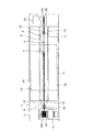
図1乃至図6は本発明の実施の一形態を示している。この摩擦撹拌接合装置では、摩擦撹拌接合で摩擦撹拌接合用ツール5を移動させる方向(以下、前後方向と定義する。)に延びるベースプレート1c上に、ベースプレート1cの長手方向に沿い平行に配した左右一対のフレーム1bと1bを、一定の間隔を置いて設置することにより、架構1を構成している、また、各フレーム1bと1bの各上端面には、上面にワーク2a,2bが載置される一対のワーク固定定盤3aと3bとがそれぞれ設置されている。各ワーク固定定盤3aと3bの上面はいずれも水平に保たれ、且つ固定定盤3aと3bとの間には、前後方向にスリット状に延びる、所定間隔を有する隙間4が形成されている。そして、隙間4の下方には、ベースプレート1cと左右のフレーム1bと左右のワーク固定定盤3a,3bとで囲まれる空間部1aが形成されている。Hereinafter, embodiments for carrying out the present invention will be described with reference to the drawings.
1 to 6 show an embodiment of the present invention. In this friction stir welding apparatus, left and right disposed in parallel along the longitudinal direction of the
空間部1aには、ボビン状をなす摩擦撹拌接合用ツール5と、摩擦撹拌接合用ツール5を上端部に備える垂直方向に延びる主軸6と、主軸6を介して摩擦撹拌接合用ツール5を回転させる主軸回転駆動装置7とを備える接合装置本体8が収納されている。また、ベースプレート1cの左右(ベースプレート1cの幅方向)両側部にそれぞれ設けられたリニアガイドレール27には、接合装置本体8の左右両側面にそれぞれ設けられたリニアガイドブロック26が係合されている。そして、リニアガイドブロック26とリニアガイドレール27とからなるリニアガイド機構9により、接合装置本体8が、摩擦撹拌接合用ツール5を隙間4より上方へ突出させた状態でベースプレート1cの長手方向となる前後方向に移動可能となっている。
In the space 1a, a friction
更に、空間部1aには移動装置10が設けられている。この移動装置10は、ベースプレート1cの前後方向における一端側の上面に設置したエンドレスウィンチ29と、エンドレスウィンチ29のドラム29aの下方に設置したシーブ30と、ベースプレート1cの前後方向における他端側の上面に設置したシーブブロック28と、エンドレスウィンチ29のドラム29aに巻き取られてシーブ30とシーブブロック28に捲き掛けられた索状物としてのワイヤロープ31とから構成されている。そして、ワイヤロープ31の両端を接合装置本体8の前後両端部に連結して、エンドレスウィンチ29の回転によりワイヤロープ31を介して接合装置本体8を前後方向に移動させることにより、摩擦撹拌接合用ツール5が前記ワーク固定定盤3a,3b間のスリット状の隙間4に沿って移動する。
Furthermore, a moving
詳述すると、架構1を構成する左右の各フレーム1bの上端に載置して取り付けられている左右一対のワーク固定定盤3a,3bは、それらの間に形成された隙間4の幅が、ベースプレート1cの長手方向と直交する幅方向において一定となるように平行に設けられている。また、左右のワーク固定定盤3a,3bの間隔(隙間4の幅)は、隙間4に下方から挿通された摩擦撹拌接合用ツール5が、隙間4内を前後方向へ支障なく移動可能となるよう設定されている。
More specifically, the pair of left and right workpiece fixing
ワーク固定定盤3a,3bの上面には、接合しようとするワーク2aと2bがそれぞれ載置される。この場合、両ワーク2aと2bは、それらの接合側端面を隙間4の上方にて近接させるような位置で、ワーク固定定盤3a,3b上に固定される。
The
また、接合装置本体8は、架構1の長手方向に延びる矩形状の底面板8a上に、左右の各側壁8b,8bを所定間隔を隔てて上下に立てて各側壁8b,8bの下端を底面板8aに固定し、更に、底面板8aの長さと略同じ長さとすると共に底面板8aよりも幅の狭い天井壁8cを、左右の側壁8b,8bの上端部内側に水平に取り付けた角筒形状のケースを形成している。この接合装置本体8は、空間部1a内に収納できる大きさを有する。また、図3に示すように、天井壁8cには、前後2個所に所定の大きさの開口部8dと8eが形成されている。
ケース内には、上下方向に延びる主軸6と、主軸6の上端とボビンツール5の軸部5bの下端との間に設けられた接合用ツール支持機構13(図6参照)と、主軸6の外周側に油冷室15を形成するための略円筒形状のケーシング16と、主軸6の上端部と下端部をケーシング16に回転自在に支持するための軸受け23,24と、ボビンツール5の外周側を冷却する気体を噴出するための冷却用ノズル17と、ACサーボモータ等の主軸回転駆動装置7とを備える。
また、主軸6の上端には、略円筒状のツールホルダー12が同軸をなすよう取り付けられている。このツールホルダー12は、摩擦撹拌接合用ツールとして使用される、ショルダー間隔が固定式のボビンツール5の軸部5bを同軸をなすよう収容し、ボビンツール5にすべりキー11を介して動力を伝達する。
更に、主軸6の下端部と主軸回転駆動装置7の下向きの出力軸7aとは、ケースの底面板8aに設けた開口部より下方に突出している。また、ケースの底面板8aの下方には、主軸回転駆動機構14が設けられている。主軸回転駆動機構14は、主軸回転駆動装置7の出力軸7aに取り付けたVプーリ20と主軸6の下端部に取り付けたVプーリ21との間に、Vベルト22を掛け回し、主軸回転駆動装置7の駆動により主軸6を回転駆動させる。
更に、主軸6及びケーシング16の上端部は、ケースの天井壁8cの開口部8dに下方より嵌入され、主軸6の上端部に支持されているツールホルダー12及び摩擦撹拌接合用ツール5は、この開口部8dを介して天井壁8cの上方に突出している。また、主軸回転駆動装置7の上端部は、天井壁8cの開口部8eに嵌入されている。
これらの構成により、接合装置本体8が、その左右両側の側壁8bの上端部と下端部にそれぞれ設けたローラ循環式のリニアガイド機構9を介して、隙間4の長手方向(前後方向)に移動自在となっている。また、隙間4からワーク固定定盤3a,3bの上方に突出するボビンツール5のプローブ5aを、ワーク固定定盤3a,3bに固定された、図中二点鎖線で示すワーク2a,2b間に位置させることにより、ワーク2a,2bの摩擦撹拌接合が実施可能となる。Further, the joining device
In the case, there are a
A substantially
Further, the lower end portion of the
Further, the upper end portion of the
With these configurations, the bonding apparatus
ここで、ボビンツール5と主軸6との接合部位の構造を更に詳しく説明する。
ツールホルダー12の内周面には、図6に示すように、ツールホルダー12の上端に連通する所要長さのキー溝12aが上下に設けられている。またボビンツール5の基端側(下側)に位置する軸部5bの外周面には、ツールホルダー12のキー溝12aよりも短い長さのキー溝5cが上下に設けられ、このキー溝5c内に、すべりキー11が固定されている。そして、キー溝12aとすべりキー11とが嵌合するようにツールホルダー12の内部にボビンツール5の軸部5bを収容することにより、ワーク2a,2bを摩擦撹拌接合する際の主軸6の回転力を、ツールホルダー12及びすべりキー11を介してボビンツール5に伝達することができる。また、すべりキー11の長さがキー溝12aよりも短いため、ボビンツール5がツールホルダー12の内側を上下に摺動することができる。
また、主軸6の上端の中心部には、下方に延びる所定深さのばね支持用支柱固定穴6aが設けられている。固定穴6aの底部には、上方に向けて延びる円柱状のばね支持用支柱18が、固定穴6aと同軸をなすよう固定されている。ばね支持用支柱18の上端は固定穴6aの上端から上方に突出し、ばね支持用支柱18の周囲には、ボビンツール5を支持するための弾性体としてのばね19が、同心状に設置されている。また、ボビンツール5の軸部5bの下端面の中心部には、ばね支持用支柱18の上端部が挿入されるばね支持用支柱挿入穴5dが設けられている。挿入穴5dにはばね支持用支柱18の上端部が挿入されると共にばね19の上端にボビンツール5の軸部5bの下端面が当接され、その結果、主軸6の上端とボビンツール5の軸部5bの下端との間には、上下方向に隙間が形成される。そして、上記構成により、ボビンツール5を、その自重をばね19により吸収しつつ下方から支持する接合用ツール支持機構13が構成されている。接合用ツール支持機構13により、ワーク2a,2bが上下方向(板厚方向)に変形していた場合でも、その変形に追従して、摩擦撹拌接合用ツールとしてのボビンツール5を、摩擦撹拌接合時にワーク2a,2bより下方からスムースに昇降動作させることができる。Here, the structure of the joint portion between the
As shown in FIG. 6, a
In addition, a spring support column fixing hole 6 a having a predetermined depth extending downward is provided at the center of the upper end of the
また、図3及び図5に示すように、ケーシング16の上端部には潤滑油を流入させる潤滑油入口16aが設けられ、ケーシング16の下端部に潤滑油を排出する潤滑油排出口16bが設けられている。また、ケーシング16内と主軸6との間には、円すいころ軸受けの如き軸受け23と、別種の軸受け24が設置された空間が、油冷室15として形成されている。そして、ベースプレート1c上に設置した潤滑油タンク25内の潤滑油を、図示してない油ポンプのような潤滑油循環装置により圧送して、ケーシング16上端部に設けた潤滑油入口16aから、主軸6上端部の軸受け23、主軸6外周側の油冷室15、主軸6下端部の軸受け24の順に、潤滑油を流通させることにより、各軸受け23,24の潤滑と主軸6の冷却とが行われる。この潤滑油は、ケーシング16下端部に設けた潤滑油排出口16bを介して潤滑油タンク25に戻され、再び上記潤滑と冷却に使用される。また、図3及び図4に示すように、接合装置本体8の上部には、ボビンツール5を冷却するための複数の冷却用ノズル17が設置されている(図ではツールホルダー12の前後に合計3基の冷却用ノズル17が設置されている)。これらの冷却用ノズル17は、基端部に図示してない気体供給源が連結される所定の長さの蛇腹部17aと、蛇腹部17aの先端側に設けた気体噴出部17bとを備え、蛇腹部17aを屈曲させることにより気体噴出部17bをボビンツール5の外周側、すなわち、ツールホルダー12の外周側の任意の位置に向けた状態で、気体供給源からの気体、たとえば、空気を噴出し、ボビンツール5を冷却する。
As shown in FIGS. 3 and 5, the upper end portion of the
リニアガイド機構9は、図3及び図5に示すように、接合装置本体8の両側部と架構1の左右のフレーム1bとの間の上端部と下端部にそれぞれ設けられて、接合装置本体8を前後方向に移動可能に支持している。このリニアガイド機構9は、接合装置本体8の側部に設けられたローラ循環式のリニアガイドブロック26と、架構1のフレーム1bの各リニアガイドブロック26に対応する位置に、フレーム1bの長手方向の全長に亘り前後に設けられた高剛性型のリニアガイドレール27とを備えている。本実施形態の場合、接合装置本体8の両側部の上端部と下端部における前端側と後端側に、図示のような断面形状を有する合計8個のリニアガイドブロック26が設けられている。また、架構1のフレーム1bの上端部と下端部の各リニアガイドブロック26に対応する位置に、、図示のような断面形状を有するリニアガイドレール27が、片側2本ずつ合計4本設置されている。更に、個々のリニアガイドレール27には、それぞれ2個のリニアガイドブロック26が前後に配置されている。
図5に示すように、リニアガイドレール27の上面と下面には略V字形状の溝27aが形成されている。また、リニアガイドブロック26には、溝27aに嵌合する突出部26aが設けられ、リニアガイドブロック26の突出部26aの斜面には、上記略V字形状の溝27aの斜面に当接する複数の転動体としての図示してない円柱状のころが、接合装置本体8の移動方向(リニアガイドレール27の延設方向)に垂直な軸回りに回転可能にそれぞれ設けられている。
上記構成を有するリニアガイドブロック26を備えることにより、摩擦撹拌接合時にベース1の幅方向に生じる大きな接合反力を、接合装置本体8の両側のリニアガイドブロック26を介して架構1に受けさせることが可能となっている。As shown in FIGS. 3 and 5, the
As shown in FIG. 5, substantially V-shaped
By providing the
移動装置10は、接合装置本体8を架構1の内部でリニアガイドレール27に沿って移動させることにより主軸6を水平移動させる。この移動装置10は、前記したように、架構1のベースプレート1cの長手方向一端側の上面に設置されたACサーボモータのような駆動装置により駆動されるエンドレスウィンチ29と、ベースプレート1cの長手方向の他端側の上面に設置された、上下2段にシーブ28aを配設してなるシーブブロック28と、エンドレスウィンチ29のドラム29aの下方に設置されたシーブ30と、エンドレスウィンチ29のドラム29aに巻かれているワイヤロープ31とからなる。
エンドレスウィンチ29のドラム29aに巻かれているワイヤロープ31の一端は、図3及び図4に示すように、接合装置本体8の移動方向の一端側の天井壁8cの上面に上下方向に回転自在に取り付けられた、連結具としてのアイプレート8fに連結されている。また、エンドレスウィンチ29のドラム29aに巻かれているワイヤロープ31の他端は、図2に示すように、シーブ30に掛けられてから、シーブブロック28の下側のシーブ28aから上側の28aの順に掛けられ、更に、図3及び図4に示すように、接合装置本体8の移動方向他端側の天井壁8c上面に上下方向に回動自在に取り付けられた、連結具としてのアイプレート8gに連結されている。これにより、ワイヤロープ31は、シーブブロック28とエンドレスウィンチ29との間に、いわば無端状に掛け渡されている。
エンドレスウィンチ29のドラム29aを一方向に回転させて、図2において、ワイヤロープ31を反時計方向に移動させると、接合装置本体8の主軸6は、図1において、エンドレスウィンチ29側に移動する。逆に、エンドレスウィンチ29のドラム29aを上記と反対方向に回転させて、図2において、ワイヤを時計方向に移動させると、接合装置本体8の主軸6は、図1において、シーブブロック28側へ移動する。そして、ボビンツール5のプローブ5aを、ワーク固定定盤3a,3bに固定されたワーク2a,2b間に位置させ、この状態で、主軸6を主軸回転駆動装置7の駆動で回転させて、摩擦撹拌接合用ツールであるボビンツール5を回転させることにより、ワーク2a,2bの接合部を下方から摩擦撹拌接合可能となる。The moving
As shown in FIGS. 3 and 4, one end of the
When the
なお、図中32は接合装置本体8の移動経路の両端部に設けられた、接合装置本体オーバーラン防止用のダンパー、33はツールホルダ12の上端部に取り付けられた、ボビンツール5の抜け出し防止用のカバーである。
In the figure, 32 is a damper for preventing overrun of the joining apparatus body provided at both ends of the moving path of the joining
上記構成を有する本発明の摩擦撹拌接合装置を用いて、たとえば、厚板(18mm以上)のアルミ材の摩擦撹拌接合を行う場合、まず、接合装置本体8を、図1、図2に示すように、架構1内の長手方向一端であるシーブブロック28側の端部に移動させた状態にして待機させる。次いで、架構1の左右のワーク固定定盤3aと3b上に、それぞれワーク2aと2bを載置させて、ワーク2aと2bの接合線を、各々図示してない位置決め治具を用いて隙間4の中心に合わせる。各ワーク固定定盤3a,3bの上面に載置されたワーク2a,2bの接合線が隙間4の中心と一致したら、各ワーク2aと2bを、ワーク固定定盤3aと3bに、図示してないワーク固定治具により固定する。その後、上記接合線を覆うように、ワーク2a,2bの全長に亘る長さの図示してない溝形鋼のような飛散防止用冶具をワーク2a,2b上に設置して、ボビンツール5の損傷による飛散を防止する。この際、ワーク2a,2bが架構1のワーク固定定盤3a,3bの上面より幅方向に大幅にはみ出してしまうほど大きい場合には、架構1の幅方向両側に、ワーク2a,2bを支持する図示してないワーク支持台を設け、これらのワーク支持台に、ワーク2a,2bのうち架構1からはみ出す部分を支持させると共に、図示してないワーク固定治具による固定を行う。
上記のようにして、ワーク2a,2bがワーク固定定盤3a,3b上に固定されると、次に、移動装置10を構成するエンドレスウィンチ29を駆動してワイヤロープ31を介し接合装置本体8を牽引させ、主軸6と共にボビンツール5を図1に示す位置よりエンドレスウィンチ29側へ移動させる。この場合、主軸6をワーク2a,2bの接合開始位置の直前まで移動させた後、隙間4の間から上向きに突出するボビンツール5のプローブ5aがワーク2a,2bの端面に掛かる(当接する)まで主軸6を微速で移動させ、ボビンツール5のプローブ5aがワーク2a,2bの端面に掛かった段階で主軸6を主軸回転駆動装置7により回転させる。また、主軸6の回転に連動させて、図示してない潤滑油循環装置による主軸6外周側の各軸受け23,24及び油冷室15への潤滑油の循環と、冷却用ノズル17からの気体、たとえば、空気の噴出を開始する。この際、ボビンツール5のプローブ5aがワーク2a,2bに容易に掛かるように、ワーク2a,2bの接合開始位置となるワーク2a,2bの接合側の一端(シーブブロック28側の端)に切り欠きを設けることが好ましい。
次に、主軸回転駆動装置7により主軸6を回転させてから所要時間経過した後、エンドレスウィンチ29の駆動でワイヤロープ31を介して接合装置本体8をエンドレスウィンチ29側へ牽引する移動を再開させて、ワーク2a,2b間の接合線の一端から、接合終了位置となるワーク接合線の他端(エンドレスウィンチ29側の端)までワーク2a,2bの摩擦撹拌接合を行う。When the friction stir welding apparatus of the present invention having the above-described configuration is used, for example, when performing friction stir welding of a thick plate (18 mm or more) aluminum material, first, the joining
When the
Next, after the
次いで、接合終了位置までワーク2a,2bの接合が完了していることを確認し、接合装置本体8の主軸6の移動を停止させる。しかる後、主軸6の回転を停止させて、ワーク2a,2b周辺の温度が下がったことを確認した後、各ワーク2a,2bの図示してないワーク固定治具による固定を解除し、接合したワーク2a,2bの回収を行い、摩擦撹拌接合を終了する。
Next, it is confirmed that the
このように、本発明の摩擦撹拌接合装置では、中空構造の架構1上に、摩擦撹拌接合の対象となるワーク2a,2bを載置するための2個1組のワーク固定定盤3a,3bを、ワーク固定定盤3a,3b同士の間にワーク2a,2b間の接合線に沿って延びる隙間4を形成するように設置している。また、隙間4の下方の空間部1aに、隙間4からプローブ5aを上方に突出させる摩擦撹拌接合用ツールとしてのボビンツール5と、ボビンツール5を上端部に取り付ける主軸6と、主軸6を回動させる主軸回転駆動装置7とを備える接合装置本体8を、接合装置本体8の左右両側の上端部と下端部に設けたローラ循環式のリニアガイド機構9を介して隙間4の長手方向に移動自在に取り付けている。そのため、摩擦撹拌接合時に生じる接合反力が大きい場合、たとえば、高速で行う薄板(たとえば、アルミ材で18mm未満)同士の摩擦撹拌接合や、厚板(たとえば、アルミ材で18mm以上)同士の摩擦撹拌接合に際して、接合反力が1tを超える場合などであったとしても、その大きな接合反力を十分に受けることができる。よって、ワーク2a,2bの摩擦撹拌接合を正常に行うことができる。
また、架構1上のワーク固定定盤3a,3bに載置したワーク2a,2bを、ワーク固定定盤3a,3b同士の間に形成した隙間4を介して下方から上向きに突出させたボビンツール5を回転させて摩擦撹拌接合するので、ワーク2a,2bの幅寸法がワーク固定定盤3a,3bの幅寸法よりも大きくても、ワーク2a,2bの摩擦撹拌接合を行うことができる。この際、ワーク2a,2bの大きさ(幅寸法)に対応させて、摩擦撹拌装置を大型化する必要もないので、摩擦撹拌装置の小型化を図ることができる。Thus, in the friction stir welding apparatus of the present invention, a set of two workpiece fixing
Further, a bobbin tool in which the
また、摩擦撹拌接合用ツールとしてのボビンツール5の下端と主軸6上端との間に、弾性体としてのばね19を設置してあるので、ボビンツール5の自重をばね19に支持させた状態で、ボビンツール5を上下動させることができる。そのため、ワーク2a,2bが上下方向(板厚方向)に変形していたとしても、その変形に追従してボビンツール5をスムースに昇降動作させることができる。
Moreover, since the
更に、摩擦接合装置本体8に、主軸6の外周側に油冷室15を形成するためのケーシング16を軸受け23,24を介して設け、各軸受け23,24と油冷室15に潤滑油を循環させるようにしたので、潤滑油により各軸受け23,24の潤滑と主軸6の冷却とを行うことができる。
Further, a
更にまた、接合装置本体8に、基端部に図示してない気体供給源が連結される蛇腹部17aと蛇腹部17aの先端側に設けた気体噴出部17bとを備え、ボビンツール5の外周側を冷却する気体の噴出方向を変更可能にした冷却用ノズル17を設置したので、気体噴出部17bをボビンツール5の外周側、すなわち、ツールホルダー12の外周側の任意の位置に向けた状態で、気体供給源からの気体、たとえば、空気を噴出させ、ボビンツール5を有効に冷却することができる。
Furthermore, the joining
また、摩擦撹拌接合用ツールとしてボビンツール5を使用しているので、摩擦撹拌接合用ツールを上下動させてワーク2a,2bに押付力を加えるための変位駆動手段の設置を省略することができる。よって、摩擦撹拌接合装置の構造の簡素化、コンパクト化を図ることができる。
In addition, since the
更に、移動装置10は、前記したように、ACサーボモータの如き駆動装置で駆動されるエンドレスウィンチ29と、エンドレスウィンチのドラム29aに巻かれて両端を接合装置本体8の移動方向両端部に連結した索状物としてのワイヤロープ31とを備えてなるので、接合装置本体8の長距離搬送(例えば、10m以上の搬送)を行うことができる。よって、ワーク2a,2bの長さが例えば10m以上であったとしても、摩擦撹拌接合を行うことができる。また、接合装置本体8を移動させる駆動手段としてエンドレスウィンチ29を用いるようにしてあるので、ラックピニオン機構を用いて接合装置本体8を移動させるようにする場合に比して、ラックを敷設する必要はなく、メンテナンスの面で有利である。更に、エンドレスウィンチ29を用いる場合は、接合装置本体8を送りねじ駆動やラックピニオン機構を用いて移動させる場合に比してコスト面でも有利である。
Further, as described above, the moving
なお、上記実施の形態では、リニアガイド機構9をローラ循環式とした場合について説明したが、厚板などの摩擦撹拌接合時に生じる大きな反力を受けられれば他のタイプのリニアガイド機構でもよい。また、上記実施の形態では、接合装置本体8の両側部の上端部と下端部における前端側と後端側に、合計8個のリニアガイドブロック26を設け、架構1のフレーム1bの上端部と下端部の各リニアガイドブロック26に対応する位置に、片側2本ずつ合計4本のリニアガイドレール27を設置したが、接合装置本体8に対するリニアガイドブロック26の設置位置及び個数、並びにリニアガイドレール27の本数は、上記した大きな反力を受けられれば、特に限定されない。更に、上記実施の形態では、個々のリニアガイドレール27に、それぞれ2個のリニアガイドブロック26が前後に配置されているが、1本のリニアガイドレール27に対し配置されるリニアガイドブロック26の個数も、上記した大きな反力を受けられれば、特に限定されない。
但し、上記実施形態の構造において、大きな反力を受けることが可能であるという本願の目的とする効果を得るためには、リニアガイド機構9が、架構1に平行に設置した複数本のリニアガイドレール27を備え、1本のリニアガイドレール27あたり複数個のリニアガイドブロック26を介して、接合装置本体8を支持していることが好ましい。In the above embodiment, the case where the
However, in order to obtain the effect of the present application that it is possible to receive a large reaction force in the structure of the above-described embodiment, the
また、上記実施の形態では、主軸回転駆動装置7にACサーボモータを適用した場合について説明したが、回転数、トルク特性などの条件が合えばインバータモータなどを適用してもよく、主軸回転駆動装置7から主軸6への回転伝達は、Vプーリ以外の歯車やチェーンによる回転伝達でもよい。
In the above embodiment, an AC servo motor is applied to the spindle
更に、接合装置本体8を移動させる移動装置10にエンドレスウィンチ29を適用した場合は、前記したように有利であるが、本発明は、エンドレスウィンチ29を用いる場合のみに限定されるものではなく、接合装置本体8を隙間4の長手方向に移動させることができれば、チェーン駆動や送りねじ駆動により移動させるようにすること、ラックピニオン機構により移動させるようにすることも含む。あるいは、ラックに代えてチェーンを前後に敷設固定し、このチェーンに、接合装置本体8が連結されたピニオンを嵌合させて、このピニオンの回転により接合装置本体8を移動させてもよい。
Furthermore, when the
更にまた、上記実施の形態では、摩擦撹拌接合用ツールにボビンツール5を適用した場合について説明したが、本発明はこれに限られるものではなく、従来の摩擦撹拌接合装置と同様に、摩擦撹拌接合用ツールをワーク2a,2bに押し付ける機構を設けて、ショルダーを一つしか持たない摩擦撹拌接合用ツールを主軸6の上端部に取り付けてもよい。また、上記実施の形態では、摩擦撹拌接合用ツール5の自重を吸収するばね19を設けた場合を示したが、ツール自重が重くない場合には、ツールの自重を吸収するばね19を省略するようにしてもよい。また、その他本発明の要旨を逸脱しない範囲内において種々変更を加え得ることは勿論である。
Furthermore, in the above-described embodiment, the case where the
本発明の摩擦撹拌接合装置によれば、ワークのサイズ及び接合反力が大きくても摩擦撹拌接合を行うことができる。 According to the friction stir welding apparatus of the present invention, friction stir welding can be performed even if the workpiece size and the reaction force are large.
1 架構、2a,2b ワーク、3a,3b ワーク固定定盤、4 隙間、5 ボビンツール(摩擦撹拌接合用ツール)、6 主軸、7 主軸回転駆動装置、8 接合装置本体、9 リニアガイド機構、10 移動装置、15 油冷室、16 ケーシング、17 冷却用ノズル、19 ばね(弾性体)、23,24 軸受け、26 リニアガイドブロック、27 リニアガイドレール、29 エンドレスウィンチ、31 ワイヤロープ(索状物)
DESCRIPTION OF
Claims (7)
この架構の上面に、上記ワーク間の接合線に沿って延びる隙間を形成するように設置された一対のワーク固定定盤と、
上記隙間の下方に位置し、上記隙間から上方に突出する摩擦撹拌接合用ツールと、
この摩擦撹拌接合用ツールを上端部に取り付ける主軸と、
この主軸を回動させる主軸回転駆動装置とを備える接合装置本体と、
この接合装置本体を上記隙間に沿って移動自在に支持するリニアガイド機構と、
上記接合装置本体を上記隙間に沿って移動させる移動装置とを備え、
上記摩擦撹拌接合用ツールをボビンツールとし、上記摩擦撹拌接合用ツールと主軸との間に、上記摩擦撹拌接合用ツールを支持する弾性体を設置し、
前記ボビンツールは、上下方向の間隔が固定とされた2つのショルダーと、これらのショルダーとの間に配置されるプローブとを有する摩擦撹拌接合装置。 A frame longer than the length of the joining line joining the workpieces,
A pair of workpiece fixing surface plates installed on the upper surface of the frame so as to form a gap extending along the joint line between the workpieces;
A friction stir welding tool located below the gap and protruding upward from the gap;
A spindle for attaching this friction stir welding tool to the upper end,
A joining apparatus main body comprising a spindle rotation driving device for rotating the spindle;
A linear guide mechanism that supports the joining apparatus body movably along the gap;
A moving device for moving the joining device main body along the gap,
The friction stir welding tool is a bobbin tool, and an elastic body that supports the friction stir welding tool is installed between the friction stir welding tool and the main shaft .
The bobbin tool is a friction stir welding apparatus having two shoulders with fixed vertical intervals and a probe arranged between the shoulders .
Applications Claiming Priority (3)
| Application Number | Priority Date | Filing Date | Title |
|---|---|---|---|
| JP2010247811 | 2010-11-04 | ||
| JP2010247811 | 2010-11-04 | ||
| PCT/JP2011/075429 WO2012060439A1 (en) | 2010-11-04 | 2011-11-04 | Friction stir welding device |
Related Child Applications (2)
| Application Number | Title | Priority Date | Filing Date |
|---|---|---|---|
| JP2014205840A Division JP5949869B2 (en) | 2010-11-04 | 2014-10-06 | Friction stir welding equipment |
| JP2014205839A Division JP5949868B2 (en) | 2010-11-04 | 2014-10-06 | Friction stir welding equipment |
Publications (2)
| Publication Number | Publication Date |
|---|---|
| JPWO2012060439A1 JPWO2012060439A1 (en) | 2014-05-12 |
| JP5937967B2 true JP5937967B2 (en) | 2016-06-22 |
Family
ID=46024552
Family Applications (4)
| Application Number | Title | Priority Date | Filing Date |
|---|---|---|---|
| JP2012541907A Expired - Fee Related JP5937967B2 (en) | 2010-11-04 | 2011-11-04 | Friction stir welding equipment |
| JP2014205839A Expired - Fee Related JP5949868B2 (en) | 2010-11-04 | 2014-10-06 | Friction stir welding equipment |
| JP2014205840A Expired - Fee Related JP5949869B2 (en) | 2010-11-04 | 2014-10-06 | Friction stir welding equipment |
| JP2016114854A Pending JP2016175129A (en) | 2010-11-04 | 2016-06-08 | Friction stir welding device |
Family Applications After (3)
| Application Number | Title | Priority Date | Filing Date |
|---|---|---|---|
| JP2014205839A Expired - Fee Related JP5949868B2 (en) | 2010-11-04 | 2014-10-06 | Friction stir welding equipment |
| JP2014205840A Expired - Fee Related JP5949869B2 (en) | 2010-11-04 | 2014-10-06 | Friction stir welding equipment |
| JP2016114854A Pending JP2016175129A (en) | 2010-11-04 | 2016-06-08 | Friction stir welding device |
Country Status (7)
| Country | Link |
|---|---|
| US (1) | US8875980B2 (en) |
| JP (4) | JP5937967B2 (en) |
| KR (1) | KR101496316B1 (en) |
| CN (1) | CN103167927B (en) |
| BR (1) | BR112013010719A2 (en) |
| SG (1) | SG190127A1 (en) |
| WO (1) | WO2012060439A1 (en) |
Families Citing this family (14)
| Publication number | Priority date | Publication date | Assignee | Title |
|---|---|---|---|---|
| EP2937169B8 (en) * | 2012-12-19 | 2018-10-17 | Mitsubishi Heavy Industries Engineering, Ltd. | Welded material manufacturing method and welding jig |
| JP6503631B2 (en) * | 2014-04-02 | 2019-04-24 | 株式会社Ihi | Work fixing device for friction stir welding device |
| JP6156579B2 (en) * | 2014-04-09 | 2017-07-05 | 株式会社Ihi | Friction stir welding equipment |
| KR101630943B1 (en) * | 2014-10-13 | 2016-06-16 | 주식회사 포스코 | Friction stir welding apparatus of highly oxidative metar and welding method for using the same |
| JP2016117071A (en) * | 2014-12-19 | 2016-06-30 | 株式会社Ihi | Welding method and friction stir welding apparatus |
| US10239152B2 (en) * | 2016-04-26 | 2019-03-26 | GM Global Technology Operations LLC | Friction stir welding bobbin tool |
| JP6766446B2 (en) * | 2016-05-25 | 2020-10-14 | 株式会社Ihi | Friction stir welding device |
| CN106392301B (en) * | 2016-11-30 | 2019-06-21 | 西北工业大学 | Friction stir welding machine and its control method |
| JP6804793B2 (en) * | 2016-12-12 | 2020-12-23 | 麻子 大河内 | Friction joining method for long flat plates |
| JP6804795B2 (en) * | 2016-12-13 | 2020-12-23 | 麻子 大河内 | Split friction joining method for long flat plates |
| JP6804794B2 (en) * | 2016-12-13 | 2020-12-23 | 麻子 大河内 | Continuous friction joining method for multiple flat plates |
| JP7018709B2 (en) | 2017-01-24 | 2022-02-14 | Thk株式会社 | Machining control system and motion guidance device |
| JP7341824B2 (en) * | 2019-09-27 | 2023-09-11 | 川崎重工業株式会社 | Double-acting friction stir point welding device and operating method of double-acting friction stir point welding device |
| CN117428321B (en) * | 2023-12-20 | 2024-02-27 | 汉德劳(常州)自动化科技有限公司 | Gantry type friction welding equipment |
Citations (9)
| Publication number | Priority date | Publication date | Assignee | Title |
|---|---|---|---|---|
| JPS63107547U (en) * | 1986-12-26 | 1988-07-11 | ||
| JPH0359518U (en) * | 1989-10-16 | 1991-06-12 | ||
| JPH1133751A (en) * | 1997-07-23 | 1999-02-09 | Hitachi Ltd | Manufacture of structural element |
| JP2000061658A (en) * | 1998-08-24 | 2000-02-29 | Hitachi Ltd | Friction welding method |
| JP2005074451A (en) * | 2003-08-29 | 2005-03-24 | Toyota Motor Corp | Friction stir welding method and friction stir welding apparatus |
| WO2006081819A1 (en) * | 2005-02-01 | 2006-08-10 | Dan Stir Aps | A device for friction stir welding and a method of welding |
| JP2007000876A (en) * | 2005-06-21 | 2007-01-11 | Kawasaki Heavy Ind Ltd | Friction stir welding apparatus |
| JP2007084067A (en) * | 2006-10-19 | 2007-04-05 | Nippon Sharyo Seizo Kaisha Ltd | Hollow extrusion and structure for railroad car |
| WO2009056759A2 (en) * | 2007-10-29 | 2009-05-07 | European Aeronautic Defence And Space Company Eads France | Double-shoulder single-actuator welding device and method for welding components using friction stir welding |
Family Cites Families (29)
| Publication number | Priority date | Publication date | Assignee | Title |
|---|---|---|---|---|
| US3816696A (en) * | 1971-12-20 | 1974-06-11 | Guild Metal Joining Equipment | Strip shearing and welding apparatus |
| JPH0249905B2 (en) | 1987-07-07 | 1990-10-31 | Inax Corp | SEJUSEMENTOSHITSUHANIKAMUPANERU |
| JPH01163484A (en) | 1987-12-19 | 1989-06-27 | Tokico Ltd | Oil injection type scroll compressor |
| JPH0359518A (en) | 1989-07-28 | 1991-03-14 | Hitachi Ltd | Display device |
| GB9125978D0 (en) | 1991-12-06 | 1992-02-05 | Welding Inst | Hot shear butt welding |
| US6516992B1 (en) | 1996-05-31 | 2003-02-11 | The Boeing Company | Friction stir welding with simultaneous cooling |
| JP3751699B2 (en) | 1996-11-25 | 2006-03-01 | 株式会社アマダエンジニアリングセンター | Friction welding equipment |
| JPH10156557A (en) | 1996-11-27 | 1998-06-16 | Amada Co Ltd | Friction welding equipment |
| JP3449403B2 (en) | 1998-07-15 | 2003-09-22 | 日本軽金属株式会社 | Probe for penetration friction stir welding |
| JP3669412B2 (en) * | 1999-01-18 | 2005-07-06 | 日本軽金属株式会社 | Rotating tool for friction stir welding |
| JP3735298B2 (en) | 2001-12-20 | 2006-01-18 | 三菱重工業株式会社 | Friction stir welding apparatus and friction stir welding method |
| US6908690B2 (en) * | 2002-04-29 | 2005-06-21 | The Boeing Company | Method and apparatus for friction stir welding |
| JP4427273B2 (en) * | 2002-07-10 | 2010-03-03 | 三菱重工業株式会社 | Structure manufacturing method and apparatus |
| JP2004114138A (en) * | 2002-09-27 | 2004-04-15 | Mitsubishi Heavy Ind Ltd | Friction stir welding machine |
| JP4335513B2 (en) | 2002-10-08 | 2009-09-30 | 三菱重工業株式会社 | Friction stir welding apparatus and friction stir welding method |
| JP2004136331A (en) * | 2002-10-18 | 2004-05-13 | Hitachi Ltd | Equipment and method for friction stir welding |
| JP2004141898A (en) * | 2002-10-23 | 2004-05-20 | Hitachi Ltd | Friction stirring and joining method and device |
| JP4198575B2 (en) | 2002-11-08 | 2008-12-17 | 川崎重工業株式会社 | Friction stir welding equipment |
| JP3740125B2 (en) * | 2003-01-16 | 2006-02-01 | 三菱重工業株式会社 | Friction stir welding apparatus and joining method thereof |
| JP4467895B2 (en) * | 2003-02-14 | 2010-05-26 | 三菱重工業株式会社 | Production method of hollow panel by friction stir welding using bobbin tool |
| JP4438409B2 (en) | 2003-12-24 | 2010-03-24 | 川崎重工業株式会社 | Friction stir welding equipment |
| JP4441284B2 (en) | 2004-02-05 | 2010-03-31 | 川崎重工業株式会社 | Friction stir welding equipment |
| JP2006198653A (en) * | 2005-01-20 | 2006-08-03 | Obara Corp | Attaching/detaching device of joining tool for friction stirring and joining |
| JP4417895B2 (en) * | 2005-09-05 | 2010-02-17 | 株式会社日立製作所 | How to make a car body |
| JP4327788B2 (en) | 2005-11-08 | 2009-09-09 | 本田技研工業株式会社 | Friction stir welding method |
| US7896216B2 (en) * | 2007-03-30 | 2011-03-01 | Kawasaki Jukogyo Kabushiki Kaisha | Sticking pad, friction stir welding machine and friction stir welding system |
| US8056793B2 (en) * | 2008-12-16 | 2011-11-15 | General Electric Company | Apparatus and method for friction surfacing using a consumable pin tool |
| JP5535502B2 (en) * | 2009-03-16 | 2014-07-02 | 川崎重工業株式会社 | Friction stir welding apparatus and method |
| FR2965196B1 (en) * | 2010-09-24 | 2012-09-07 | Serimax | IMPROVED WELDING DEVICE |
-
2011
- 2011-11-04 CN CN201180052035.4A patent/CN103167927B/en not_active Expired - Fee Related
- 2011-11-04 BR BR112013010719A patent/BR112013010719A2/en not_active Application Discontinuation
- 2011-11-04 JP JP2012541907A patent/JP5937967B2/en not_active Expired - Fee Related
- 2011-11-04 KR KR1020137010476A patent/KR101496316B1/en active IP Right Grant
- 2011-11-04 WO PCT/JP2011/075429 patent/WO2012060439A1/en active Application Filing
- 2011-11-04 US US13/882,261 patent/US8875980B2/en not_active Expired - Fee Related
- 2011-11-04 SG SG2013034038A patent/SG190127A1/en unknown
-
2014
- 2014-10-06 JP JP2014205839A patent/JP5949868B2/en not_active Expired - Fee Related
- 2014-10-06 JP JP2014205840A patent/JP5949869B2/en not_active Expired - Fee Related
-
2016
- 2016-06-08 JP JP2016114854A patent/JP2016175129A/en active Pending
Patent Citations (9)
| Publication number | Priority date | Publication date | Assignee | Title |
|---|---|---|---|---|
| JPS63107547U (en) * | 1986-12-26 | 1988-07-11 | ||
| JPH0359518U (en) * | 1989-10-16 | 1991-06-12 | ||
| JPH1133751A (en) * | 1997-07-23 | 1999-02-09 | Hitachi Ltd | Manufacture of structural element |
| JP2000061658A (en) * | 1998-08-24 | 2000-02-29 | Hitachi Ltd | Friction welding method |
| JP2005074451A (en) * | 2003-08-29 | 2005-03-24 | Toyota Motor Corp | Friction stir welding method and friction stir welding apparatus |
| WO2006081819A1 (en) * | 2005-02-01 | 2006-08-10 | Dan Stir Aps | A device for friction stir welding and a method of welding |
| JP2007000876A (en) * | 2005-06-21 | 2007-01-11 | Kawasaki Heavy Ind Ltd | Friction stir welding apparatus |
| JP2007084067A (en) * | 2006-10-19 | 2007-04-05 | Nippon Sharyo Seizo Kaisha Ltd | Hollow extrusion and structure for railroad car |
| WO2009056759A2 (en) * | 2007-10-29 | 2009-05-07 | European Aeronautic Defence And Space Company Eads France | Double-shoulder single-actuator welding device and method for welding components using friction stir welding |
Also Published As
| Publication number | Publication date |
|---|---|
| JP2015003344A (en) | 2015-01-08 |
| WO2012060439A1 (en) | 2012-05-10 |
| CN103167927B (en) | 2015-10-14 |
| KR101496316B1 (en) | 2015-02-26 |
| BR112013010719A2 (en) | 2016-08-16 |
| JP5949869B2 (en) | 2016-07-13 |
| US20130221069A1 (en) | 2013-08-29 |
| JP5949868B2 (en) | 2016-07-13 |
| JPWO2012060439A1 (en) | 2014-05-12 |
| JP2015027701A (en) | 2015-02-12 |
| JP2016175129A (en) | 2016-10-06 |
| KR20130093124A (en) | 2013-08-21 |
| CN103167927A (en) | 2013-06-19 |
| SG190127A1 (en) | 2013-06-28 |
| US8875980B2 (en) | 2014-11-04 |
Similar Documents
| Publication | Publication Date | Title |
|---|---|---|
| JP5949868B2 (en) | Friction stir welding equipment | |
| KR100499838B1 (en) | Machine tool and cover device for the machine tool | |
| US9475209B2 (en) | Wire saw and workpiece machining method employing same | |
| JP4814373B2 (en) | Device for moving workpiece and / or machining remainder and device for machining workpiece | |
| JP2011189998A (en) | Method and apparatus for transporting pallet | |
| JP2019202337A (en) | Laser processing machine | |
| KR20180077788A (en) | Driving apparatus of mobile rack | |
| WO2014125625A1 (en) | Festoon device | |
| KR101078838B1 (en) | Ribbon wire winding equipment of ribbon wire manufacturing installation | |
| KR20120010617A (en) | Rail carriage assembly | |
| JP2005219160A (en) | Horizontal band saw machine | |
| KR20030050102A (en) | Strip side guide apparatus | |
| JP2012184101A (en) | Punching device | |
| JP6068997B2 (en) | Cutting machine | |
| KR101177563B1 (en) | cutting device for welding bead of T-profile using a steel curtainwall | |
| KR101785334B1 (en) | A apparatus for transferring the material by a pitch | |
| KR200497778Y1 (en) | Apparatus for taping hoses | |
| RU2381897C1 (en) | Device for sawing of stone with diamond rope (versions) | |
| KR101798862B1 (en) | A apparatus for transferring the material by a pitch | |
| JPS6023115Y2 (en) | Backing device for vertical joint welding of cylindrical objects | |
| JP2017209703A (en) | Friction agitation joint device | |
| CN117645100A (en) | Composite transmission device and battery drying equipment | |
| SU1070287A1 (en) | Machine for grinding plaster layer | |
| JP2017192956A (en) | Friction stirring joining device | |
| KR200334709Y1 (en) | An apparatus for cleaning a conveyor belt |
Legal Events
| Date | Code | Title | Description |
|---|---|---|---|
| A521 | Request for written amendment filed |
Free format text: JAPANESE INTERMEDIATE CODE: A523 Effective date: 20140331 |
|
| A521 | Request for written amendment filed |
Free format text: JAPANESE INTERMEDIATE CODE: A821 Effective date: 20140401 |
|
| A131 | Notification of reasons for refusal |
Free format text: JAPANESE INTERMEDIATE CODE: A131 Effective date: 20140805 |
|
| A521 | Request for written amendment filed |
Free format text: JAPANESE INTERMEDIATE CODE: A821 Effective date: 20141007 |
|
| A02 | Decision of refusal |
Free format text: JAPANESE INTERMEDIATE CODE: A02 Effective date: 20150602 |
|
| A521 | Request for written amendment filed |
Free format text: JAPANESE INTERMEDIATE CODE: A523 Effective date: 20150901 |
|
| A521 | Request for written amendment filed |
Free format text: JAPANESE INTERMEDIATE CODE: A821 Effective date: 20150902 |
|
| A911 | Transfer to examiner for re-examination before appeal (zenchi) |
Free format text: JAPANESE INTERMEDIATE CODE: A911 Effective date: 20150909 |
|
| A912 | Re-examination (zenchi) completed and case transferred to appeal board |
Free format text: JAPANESE INTERMEDIATE CODE: A912 Effective date: 20151204 |
|
| A61 | First payment of annual fees (during grant procedure) |
Free format text: JAPANESE INTERMEDIATE CODE: A61 Effective date: 20160513 |
|
| R150 | Certificate of patent or registration of utility model |
Ref document number: 5937967 Country of ref document: JP Free format text: JAPANESE INTERMEDIATE CODE: R150 |
|
| R250 | Receipt of annual fees |
Free format text: JAPANESE INTERMEDIATE CODE: R250 |
|
| R250 | Receipt of annual fees |
Free format text: JAPANESE INTERMEDIATE CODE: R250 |
|
| LAPS | Cancellation because of no payment of annual fees |