JP5930881B2 - Gear structure and sheet manufacturing apparatus - Google Patents
Gear structure and sheet manufacturing apparatus Download PDFInfo
- Publication number
- JP5930881B2 JP5930881B2 JP2012147976A JP2012147976A JP5930881B2 JP 5930881 B2 JP5930881 B2 JP 5930881B2 JP 2012147976 A JP2012147976 A JP 2012147976A JP 2012147976 A JP2012147976 A JP 2012147976A JP 5930881 B2 JP5930881 B2 JP 5930881B2
- Authority
- JP
- Japan
- Prior art keywords
- gear
- tooth
- gear structure
- gears
- sheet
- Prior art date
- Legal status (The legal status is an assumption and is not a legal conclusion. Google has not performed a legal analysis and makes no representation as to the accuracy of the status listed.)
- Expired - Fee Related
Links
Images


Classifications
-
- B—PERFORMING OPERATIONS; TRANSPORTING
- B29—WORKING OF PLASTICS; WORKING OF SUBSTANCES IN A PLASTIC STATE IN GENERAL
- B29C—SHAPING OR JOINING OF PLASTICS; SHAPING OF MATERIAL IN A PLASTIC STATE, NOT OTHERWISE PROVIDED FOR; AFTER-TREATMENT OF THE SHAPED PRODUCTS, e.g. REPAIRING
- B29C48/00—Extrusion moulding, i.e. expressing the moulding material through a die or nozzle which imparts the desired form; Apparatus therefor
- B29C48/25—Component parts, details or accessories; Auxiliary operations
- B29C48/36—Means for plasticising or homogenising the moulding material or forcing it through the nozzle or die
- B29C48/50—Details of extruders
- B29C48/505—Screws
- B29C48/54—Screws with additional forward-feeding elements
-
- B—PERFORMING OPERATIONS; TRANSPORTING
- B29—WORKING OF PLASTICS; WORKING OF SUBSTANCES IN A PLASTIC STATE IN GENERAL
- B29C—SHAPING OR JOINING OF PLASTICS; SHAPING OF MATERIAL IN A PLASTIC STATE, NOT OTHERWISE PROVIDED FOR; AFTER-TREATMENT OF THE SHAPED PRODUCTS, e.g. REPAIRING
- B29C48/00—Extrusion moulding, i.e. expressing the moulding material through a die or nozzle which imparts the desired form; Apparatus therefor
- B29C48/25—Component parts, details or accessories; Auxiliary operations
- B29C48/36—Means for plasticising or homogenising the moulding material or forcing it through the nozzle or die
- B29C48/50—Details of extruders
- B29C48/505—Screws
- B29C48/63—Screws having sections without mixing elements or threads, i.e. having cylinder shaped sections
-
- B—PERFORMING OPERATIONS; TRANSPORTING
- B29—WORKING OF PLASTICS; WORKING OF SUBSTANCES IN A PLASTIC STATE IN GENERAL
- B29C—SHAPING OR JOINING OF PLASTICS; SHAPING OF MATERIAL IN A PLASTIC STATE, NOT OTHERWISE PROVIDED FOR; AFTER-TREATMENT OF THE SHAPED PRODUCTS, e.g. REPAIRING
- B29C43/00—Compression moulding, i.e. applying external pressure to flow the moulding material; Apparatus therefor
- B29C43/22—Compression moulding, i.e. applying external pressure to flow the moulding material; Apparatus therefor of articles of indefinite length
- B29C43/28—Compression moulding, i.e. applying external pressure to flow the moulding material; Apparatus therefor of articles of indefinite length incorporating preformed parts or layers, e.g. compression moulding around inserts or for coating articles
-
- B—PERFORMING OPERATIONS; TRANSPORTING
- B29—WORKING OF PLASTICS; WORKING OF SUBSTANCES IN A PLASTIC STATE IN GENERAL
- B29C—SHAPING OR JOINING OF PLASTICS; SHAPING OF MATERIAL IN A PLASTIC STATE, NOT OTHERWISE PROVIDED FOR; AFTER-TREATMENT OF THE SHAPED PRODUCTS, e.g. REPAIRING
- B29C43/00—Compression moulding, i.e. applying external pressure to flow the moulding material; Apparatus therefor
- B29C43/32—Component parts, details or accessories; Auxiliary operations
- B29C43/44—Compression means for making articles of indefinite length
- B29C43/46—Rollers
-
- B—PERFORMING OPERATIONS; TRANSPORTING
- B29—WORKING OF PLASTICS; WORKING OF SUBSTANCES IN A PLASTIC STATE IN GENERAL
- B29C—SHAPING OR JOINING OF PLASTICS; SHAPING OF MATERIAL IN A PLASTIC STATE, NOT OTHERWISE PROVIDED FOR; AFTER-TREATMENT OF THE SHAPED PRODUCTS, e.g. REPAIRING
- B29C48/00—Extrusion moulding, i.e. expressing the moulding material through a die or nozzle which imparts the desired form; Apparatus therefor
- B29C48/25—Component parts, details or accessories; Auxiliary operations
- B29C48/36—Means for plasticising or homogenising the moulding material or forcing it through the nozzle or die
- B29C48/365—Means for plasticising or homogenising the moulding material or forcing it through the nozzle or die using pumps, e.g. piston pumps
- B29C48/37—Gear pumps
-
- B—PERFORMING OPERATIONS; TRANSPORTING
- B29—WORKING OF PLASTICS; WORKING OF SUBSTANCES IN A PLASTIC STATE IN GENERAL
- B29C—SHAPING OR JOINING OF PLASTICS; SHAPING OF MATERIAL IN A PLASTIC STATE, NOT OTHERWISE PROVIDED FOR; AFTER-TREATMENT OF THE SHAPED PRODUCTS, e.g. REPAIRING
- B29C48/00—Extrusion moulding, i.e. expressing the moulding material through a die or nozzle which imparts the desired form; Apparatus therefor
- B29C48/25—Component parts, details or accessories; Auxiliary operations
- B29C48/36—Means for plasticising or homogenising the moulding material or forcing it through the nozzle or die
- B29C48/395—Means for plasticising or homogenising the moulding material or forcing it through the nozzle or die using screws surrounded by a cooperating barrel, e.g. single screw extruders
- B29C48/40—Means for plasticising or homogenising the moulding material or forcing it through the nozzle or die using screws surrounded by a cooperating barrel, e.g. single screw extruders using two or more parallel screws or at least two parallel non-intermeshing screws, e.g. twin screw extruders
- B29C48/405—Intermeshing co-rotating screws
-
- B—PERFORMING OPERATIONS; TRANSPORTING
- B29—WORKING OF PLASTICS; WORKING OF SUBSTANCES IN A PLASTIC STATE IN GENERAL
- B29C—SHAPING OR JOINING OF PLASTICS; SHAPING OF MATERIAL IN A PLASTIC STATE, NOT OTHERWISE PROVIDED FOR; AFTER-TREATMENT OF THE SHAPED PRODUCTS, e.g. REPAIRING
- B29C48/00—Extrusion moulding, i.e. expressing the moulding material through a die or nozzle which imparts the desired form; Apparatus therefor
- B29C48/25—Component parts, details or accessories; Auxiliary operations
- B29C48/36—Means for plasticising or homogenising the moulding material or forcing it through the nozzle or die
- B29C48/465—Means for plasticising or homogenising the moulding material or forcing it through the nozzle or die using rollers
-
- B—PERFORMING OPERATIONS; TRANSPORTING
- B29—WORKING OF PLASTICS; WORKING OF SUBSTANCES IN A PLASTIC STATE IN GENERAL
- B29C—SHAPING OR JOINING OF PLASTICS; SHAPING OF MATERIAL IN A PLASTIC STATE, NOT OTHERWISE PROVIDED FOR; AFTER-TREATMENT OF THE SHAPED PRODUCTS, e.g. REPAIRING
- B29C48/00—Extrusion moulding, i.e. expressing the moulding material through a die or nozzle which imparts the desired form; Apparatus therefor
- B29C48/25—Component parts, details or accessories; Auxiliary operations
- B29C48/36—Means for plasticising or homogenising the moulding material or forcing it through the nozzle or die
- B29C48/50—Details of extruders
- B29C48/505—Screws
- B29C48/535—Screws with thread pitch varying along the longitudinal axis
-
- B—PERFORMING OPERATIONS; TRANSPORTING
- B29—WORKING OF PLASTICS; WORKING OF SUBSTANCES IN A PLASTIC STATE IN GENERAL
- B29C—SHAPING OR JOINING OF PLASTICS; SHAPING OF MATERIAL IN A PLASTIC STATE, NOT OTHERWISE PROVIDED FOR; AFTER-TREATMENT OF THE SHAPED PRODUCTS, e.g. REPAIRING
- B29C48/00—Extrusion moulding, i.e. expressing the moulding material through a die or nozzle which imparts the desired form; Apparatus therefor
- B29C48/25—Component parts, details or accessories; Auxiliary operations
- B29C48/36—Means for plasticising or homogenising the moulding material or forcing it through the nozzle or die
- B29C48/50—Details of extruders
- B29C48/505—Screws
- B29C48/55—Screws having reverse-feeding elements
-
- B—PERFORMING OPERATIONS; TRANSPORTING
- B29—WORKING OF PLASTICS; WORKING OF SUBSTANCES IN A PLASTIC STATE IN GENERAL
- B29C—SHAPING OR JOINING OF PLASTICS; SHAPING OF MATERIAL IN A PLASTIC STATE, NOT OTHERWISE PROVIDED FOR; AFTER-TREATMENT OF THE SHAPED PRODUCTS, e.g. REPAIRING
- B29C48/00—Extrusion moulding, i.e. expressing the moulding material through a die or nozzle which imparts the desired form; Apparatus therefor
- B29C48/25—Component parts, details or accessories; Auxiliary operations
- B29C48/36—Means for plasticising or homogenising the moulding material or forcing it through the nozzle or die
- B29C48/50—Details of extruders
- B29C48/505—Screws
- B29C48/57—Screws provided with kneading disc-like elements, e.g. with oval-shaped elements
-
- B—PERFORMING OPERATIONS; TRANSPORTING
- B29—WORKING OF PLASTICS; WORKING OF SUBSTANCES IN A PLASTIC STATE IN GENERAL
- B29C—SHAPING OR JOINING OF PLASTICS; SHAPING OF MATERIAL IN A PLASTIC STATE, NOT OTHERWISE PROVIDED FOR; AFTER-TREATMENT OF THE SHAPED PRODUCTS, e.g. REPAIRING
- B29C48/00—Extrusion moulding, i.e. expressing the moulding material through a die or nozzle which imparts the desired form; Apparatus therefor
- B29C48/25—Component parts, details or accessories; Auxiliary operations
- B29C48/36—Means for plasticising or homogenising the moulding material or forcing it through the nozzle or die
- B29C48/50—Details of extruders
- B29C48/505—Screws
- B29C48/585—Screws provided with gears interacting with the flow
-
- B—PERFORMING OPERATIONS; TRANSPORTING
- B29—WORKING OF PLASTICS; WORKING OF SUBSTANCES IN A PLASTIC STATE IN GENERAL
- B29C—SHAPING OR JOINING OF PLASTICS; SHAPING OF MATERIAL IN A PLASTIC STATE, NOT OTHERWISE PROVIDED FOR; AFTER-TREATMENT OF THE SHAPED PRODUCTS, e.g. REPAIRING
- B29C43/00—Compression moulding, i.e. applying external pressure to flow the moulding material; Apparatus therefor
- B29C43/32—Component parts, details or accessories; Auxiliary operations
- B29C43/34—Feeding the material to the mould or the compression means
- B29C2043/3433—Feeding the material to the mould or the compression means using dispensing heads, e.g. extruders, placed over or apart from the moulds
-
- B—PERFORMING OPERATIONS; TRANSPORTING
- B29—WORKING OF PLASTICS; WORKING OF SUBSTANCES IN A PLASTIC STATE IN GENERAL
- B29C—SHAPING OR JOINING OF PLASTICS; SHAPING OF MATERIAL IN A PLASTIC STATE, NOT OTHERWISE PROVIDED FOR; AFTER-TREATMENT OF THE SHAPED PRODUCTS, e.g. REPAIRING
- B29C43/00—Compression moulding, i.e. applying external pressure to flow the moulding material; Apparatus therefor
- B29C43/32—Component parts, details or accessories; Auxiliary operations
- B29C43/44—Compression means for making articles of indefinite length
- B29C43/46—Rollers
- B29C2043/468—Rollers take-off rollers, i.e. arranged adjacent a material feeding device
-
- H—ELECTRICITY
- H01—ELECTRIC ELEMENTS
- H01L—SEMICONDUCTOR DEVICES NOT COVERED BY CLASS H10
- H01L2924/00—Indexing scheme for arrangements or methods for connecting or disconnecting semiconductor or solid-state bodies as covered by H01L24/00
- H01L2924/0001—Technical content checked by a classifier
- H01L2924/0002—Not covered by any one of groups H01L24/00, H01L24/00 and H01L2224/00
Landscapes
- Engineering & Computer Science (AREA)
- Mechanical Engineering (AREA)
- Extrusion Moulding Of Plastics Or The Like (AREA)
- Processing And Handling Of Plastics And Other Materials For Molding In General (AREA)
- Registering, Tensioning, Guiding Webs, And Rollers Therefor (AREA)
- Manufacture Of Macromolecular Shaped Articles (AREA)
- Compositions Of Macromolecular Compounds (AREA)
- Sealing Material Composition (AREA)
- Structures Or Materials For Encapsulating Or Coating Semiconductor Devices Or Solid State Devices (AREA)
Description
本発明は、ギヤ構造体およびシート製造装置、詳しくは、粒子と樹脂成分とを含有する組成物の搬送に用いられるギヤ構造体およびそれを備えるシート製造装置に関する。 The present invention relates to a gear structure and a sheet manufacturing apparatus, and more particularly to a gear structure used for conveying a composition containing particles and a resin component, and a sheet manufacturing apparatus including the gear structure.
従来、溶融樹脂を含む流体の搬送において、1対のギヤを備えるギヤポンプが知られている。 Conventionally, a gear pump including a pair of gears is known for transporting a fluid containing a molten resin.
例えば、ロータ軸およびそれが延びる方向に沿う歯筋の歯車部を有する1対のギヤ(ギヤロータ)と、歯車部を収容し、ロータ軸を回転自在に支持するハウジングとを備えるギヤポンプが提案されている(例えば、下記特許文献1参照。)。
For example, there has been proposed a gear pump including a pair of gears (gear rotor) having a rotor shaft and a gear portion of a tooth trace along a direction in which the rotor shaft extends, and a housing that houses the gear portion and rotatably supports the rotor shaft. (For example, refer to
特許文献1のギヤポンプでは、ロータ軸の回転駆動によって、歯車部が回転して、それによって、ハウジングと歯溝とによって区画される空間の移動によって、ハウジングの上流側の上流空間にある溶融樹脂を、ハウジングの下流側の下流空間に搬送している。
In the gear pump of
近年、種々の物性を有する粒子を樹脂成分に混合した組成物を幅広のシート状で搬送したい要求があり、その要求を満足するために、回転軸線方向に対して傾斜するねじ山状の斜歯をギヤに設けることが試案される。 In recent years, there has been a demand for conveying a composition in which particles having various physical properties are mixed with a resin component in a wide sheet form, and in order to satisfy the demand, a thread-like oblique tooth inclined with respect to the rotation axis direction is required. It is tentative to install a gear on the gear.
しかし、ハウジングの上流空間および下流空間が、斜歯間の歯溝を介して連通すると、搬送効率が低下する不具合がある。 However, if the upstream space and the downstream space of the housing communicate with each other via the tooth spaces between the inclined teeth, there is a problem that the conveyance efficiency is lowered.
とりわけ、組成物を幅広のシート状で搬送するには、ギヤの長さ(回転軸線方向長さ)を比較的長くする必要があり、そのような長いギヤに設けられるねじ山状の斜歯の歯溝では、上記した連通がより発生し易くなる。そのため、搬送効率が格段に低下する。 In particular, in order to convey the composition in the form of a wide sheet, it is necessary to make the length of the gear (the length in the rotational axis direction) relatively long. In the tooth gap, the above-described communication is more likely to occur. As a result, the conveyance efficiency is significantly reduced.
さらに、組成物が粒子を含有するため、高い剪断力を組成物に付与する要求がある一方、上記した連通が生じるとそのような要求を満足することができないという不具合がある。 Furthermore, since the composition contains particles, there is a demand for imparting a high shearing force to the composition. On the other hand, when the above-described communication occurs, such a demand cannot be satisfied.
本発明の目的は、粒子および樹脂組成物を含有する組成物を高い剪断力を付与しながら、高い効率で幅広のシート状で搬送することのできるギヤ構造物およびそれを備えるシート製造装置を提供することにある。 An object of the present invention is to provide a gear structure capable of conveying a composition containing particles and a resin composition in a wide sheet shape with high efficiency while applying a high shearing force, and a sheet manufacturing apparatus including the gear structure. There is to do.
上記目的を達成するために、本発明のギヤ構造体は、1対のギヤと、前記1対のギヤを収容するケーシングとを備え、粒子と樹脂成分とを含有する組成物を、前記ギヤの回転軸線方向に変形させながら搬送するように構成される前記ギヤ構造体であり、前記1対のギヤのそれぞれは、互いに噛み合う斜歯を備え、前記斜歯は、回転軸線方向に互いに隣接配置され、歯筋が互いに異なる第1斜歯および第2斜歯を備え、前記第1斜歯および前記第2斜歯の歯筋は、前記ギヤの回転方向下流側から回転方向上流側に向かうに従って、回転軸線方向の外側に傾斜し、前記ケーシングには、前記1対のギヤを、前記斜歯と前記ケーシングの内側面との間に密閉空間が形成されるように、収容する収容空間が設けられ、前記密閉空間に対する搬送方向上流側の上流空間と、前記密閉空間に対する搬送方向下流側の下流空間とが、前記歯筋間の歯溝を介して連通しないように、前記1対のギヤが構成されていることを特徴としている。 In order to achieve the above object, a gear structure of the present invention comprises a pair of gears and a casing that accommodates the pair of gears, and a composition containing particles and a resin component is added to the gear structure. The gear structure is configured to convey while being deformed in a rotation axis direction, and each of the pair of gears includes an oblique tooth that meshes with each other, and the oblique tooth is arranged adjacent to each other in the rotation axis direction. The first oblique teeth and the second oblique teeth are different from each other, and the first oblique teeth and the second oblique tooth traces move from the downstream side in the rotational direction of the gear toward the upstream side in the rotational direction. The casing is provided with an accommodation space that is inclined outward in the rotational axis direction and accommodates the pair of gears so that a sealed space is formed between the inclined teeth and the inner surface of the casing. , In the conveying direction with respect to the sealed space The pair of gears is configured so that the upstream space on the side and the downstream space on the downstream side in the transport direction with respect to the sealed space do not communicate with each other via the tooth spaces between the tooth traces. .
このギヤ構造体によれば、粒子と樹脂成分とを含有する組成物を、ギヤの回転軸線方向に変形させながらシートで搬送することができる。 According to this gear structure, a composition containing particles and a resin component can be conveyed by a sheet while being deformed in the rotational axis direction of the gear.
また、1対のギヤの噛み合いによって、組成物に高い剪断力を付与して、それによって、粒子を樹脂中に分散させることができる。 Also, the engagement of a pair of gears can impart a high shear force to the composition, thereby dispersing the particles in the resin.
さらに、第1斜歯および第2斜歯の歯筋は、ギヤの回転方向下流側から回転方向上流側に向かうに従って、回転軸線方向の外側に傾斜しているので、組成物は、回転軸線方向の両外側に広がるように、確実に押し広げられながら、搬送される。そのため、組成物をシートとして確実に形成することができる。 Further, since the tooth traces of the first and second inclined teeth are inclined outward in the rotational axis direction from the downstream side in the rotational direction of the gear toward the upstream side in the rotational direction, the composition is in the rotational axis direction. It is transported while being securely spread so as to spread on both outer sides. Therefore, the composition can be reliably formed as a sheet.
そして、密閉空間に対する搬送方向上流側の上流空間と、密閉空間に対する搬送方向下流側の下流空間とが、歯筋間の歯溝を介して連通しないように、1対のギヤが構成されているため、組成物が上流空間と下流空間との間の歯溝を介する組成物の自由な移動を規制して、ギヤの回転に基づいて回転方向上流側から下流側に向かう歯溝の移動に伴って、組成物を搬送することができる。 The pair of gears is configured so that the upstream space on the upstream side in the transport direction with respect to the sealed space and the downstream space on the downstream side in the transport direction with respect to the sealed space do not communicate with each other via the tooth spaces between the tooth traces. Therefore, the composition restricts the free movement of the composition through the tooth gap between the upstream space and the downstream space, and the tooth groove moves from the upstream side to the downstream side in the rotation direction based on the rotation of the gear. The composition can be conveyed.
そのため、粒子および樹脂成分を含有する組成物に高い剪断力を付与しながら、高い効率で幅広のシートを搬送することができる。 Therefore, a wide sheet can be conveyed with high efficiency while applying a high shearing force to the composition containing particles and a resin component.
また、本発明のギヤ構造体では、前記第1斜歯の前記歯溝、および、前記第2斜歯の前記歯溝は、それぞれ互いに連通し、前記第1斜歯の前記歯溝および前記第2斜歯の前記歯溝において、回転軸線方向の全てにわたって、回転軸線から径方向に投影したときに、前記ケーシングの前記内側面と重複する重複歯溝が少なくとも1つ形成されることが好適である。 In the gear structure of the present invention, the tooth groove of the first oblique tooth and the tooth groove of the second oblique tooth are communicated with each other, and the tooth groove of the first oblique tooth and the first tooth tooth In the tooth groove of two oblique teeth, it is preferable that at least one overlapping tooth groove overlapping the inner side surface of the casing is formed when projected in the radial direction from the rotation axis over the entire rotation axis. is there.
このギヤ構造体では、第1斜歯の歯溝および第2斜歯の歯溝には、回転軸線方向の全てにわたって、回転軸線から径方向に投影したときに、ケーシングの内側面と重複する重複歯溝が少なくとも1つ形成されるため、重複歯溝によって、上流空間と下流空間との歯溝を介する連通を確実に阻止することができる。 In this gear structure, the first oblique tooth groove and the second oblique tooth groove overlap with the inner surface of the casing when projected radially from the rotation axis over the entire rotation axis. Since at least one tooth gap is formed, the overlapping tooth gap can reliably prevent communication between the upstream space and the downstream space via the tooth gap.
また、本発明のギヤ構造体では、歯筋に交差する方向に延びることにより、歯溝を仕切り、組成物が歯溝に沿って回転軸線方向に移動することを阻止するための仕切り部をさらに備えていることが好適である。 In the gear structure of the present invention, the tooth structure is further divided by extending in a direction intersecting with the tooth trace, and a partition portion for preventing the composition from moving in the rotation axis direction along the tooth groove is further provided. It is suitable to have.
このギヤ構造体によれば、仕切り部が、組成物が歯溝に沿って回転軸線方向に移動することを阻止するので、上流空間と下流空間との歯筋間の歯溝を介する連通を確実に防止することができる。 According to this gear structure, since the partition portion prevents the composition from moving in the rotation axis direction along the tooth gap, the communication between the tooth spaces between the upstream space and the downstream space is ensured. Can be prevented.
そのため、シートの搬送効率を向上させることができる。 Therefore, the sheet conveyance efficiency can be improved.
また、本発明のギヤ構造体では、前記仕切り部は、前記1対のギヤのいずれか一方に設けられ、前記ギヤの歯たけと同じかそれより高く、前記ギヤの周方向に沿って連続して形成される主仕切り部と、前記1対のギヤの他方において、前記主仕切り部に対応して設けられ、前記ギヤの歯溝と同じかそれより低く、前記ギヤの周方向に沿って連続して形成される第1補助仕切り部と、前記ケーシングにおいて、前記主仕切り部および/または前記第1補助仕切り部に対応するように凹凸形成される第2補助仕切り部とを備えていることが好適である。 In the gear structure of the present invention, the partition portion is provided on any one of the pair of gears, and is equal to or higher than the gear teeth of the gear, and is continuous along the circumferential direction of the gear. The other of the pair of gears is provided corresponding to the main partition, and is equal to or lower than the tooth gap of the gear and is continuous along the circumferential direction of the gear. The first auxiliary partition portion formed in the above-described manner, and the casing includes a second auxiliary partition portion that is unevenly formed so as to correspond to the main partition portion and / or the first auxiliary partition portion. Is preferred.
このギヤ構造体では、主仕切り部、第1補助仕切り部および第2補助仕切り部によって、上流空間と下流空間との歯筋間の歯溝を介する連通をより一層確実に防止することができる。 In this gear structure, the main partition portion, the first auxiliary partition portion, and the second auxiliary partition portion can more reliably prevent communication between the tooth spaces between the tooth spaces in the upstream space and the downstream space.
そのため、シートの搬送効率をより一層向上させることができる。 Therefore, the sheet conveyance efficiency can be further improved.
また、本発明のギヤ構造体では、前記1対のギヤの回転軸線方向長さが、200mm以上であることが好適である。 In the gear structure of the present invention, it is preferable that the length of the pair of gears in the rotation axis direction is 200 mm or more.
このギヤ構造体によれば、1対のギヤの回転軸線方向長さが200mm以上であるので、幅広のシートを確実に搬送することができる。 According to this gear structure, since the length of the pair of gears in the rotation axis direction is 200 mm or more, a wide sheet can be reliably conveyed.
また、本発明のギヤ構造体は、前記粒子の体積割合が30体積%を超過する前記組成物を搬送するように構成されていることが好適である。 Moreover, it is preferable that the gear structure of the present invention is configured to convey the composition in which the volume ratio of the particles exceeds 30% by volume.
このギヤ構造体では、粒子の体積割合が30体積%を超過する組成物であっても、1対のギヤの噛み合いに基づく高い剪断力によって、粒子が分散された組成物をシートとして搬送することができる。 In this gear structure, a composition in which particles are dispersed is conveyed as a sheet by a high shearing force based on meshing of a pair of gears even if the composition has a volume ratio exceeding 30 volume%. Can do.
本発明のシート製造装置は、粒子と樹脂成分とを含有する組成物からシートを製造するように構成されるシート製造装置であって、上記したギヤ構造体、および、前記ギヤ構造体の搬送方向下流側に設けられ、前記組成物を支持して搬送するように構成される移動支持体と、前記移動支持体に対して隙間が設けられるように対向配置されるドクターとを備えるシート調整部であって、前記組成物を前記隙間に通過させるように構成される前記シート調整部を備えることを特徴としている。 The sheet manufacturing apparatus of the present invention is a sheet manufacturing apparatus configured to manufacture a sheet from a composition containing particles and a resin component, and includes the above-described gear structure and a conveyance direction of the gear structure. A sheet adjusting unit comprising a moving support configured to be provided on the downstream side and configured to support and convey the composition, and a doctor arranged to face the moving support so that a gap is provided. The sheet adjusting unit is configured to pass the composition through the gap.
このシート製造装置では、組成物を、ギヤ構造体を用いてその回転軸線方向に変形させながらシートに確実に搬送させた後、軸線方向に変形されたシートを移動支持体により支持して搬送させながら、ドクターとの隙間に通過させる。 In this sheet manufacturing apparatus, the composition is reliably conveyed to the sheet while being deformed in the rotational axis direction using the gear structure, and then the sheet deformed in the axial direction is supported by the movable support and conveyed. While passing through the gap with the doctor.
そのため、シートを画一的に製造することができる。 Therefore, the sheet can be manufactured uniformly.
また、本発明のシート製造装置は、前記ギヤ構造体の搬送方向上流側に設けれ、前記粒子と前記樹脂成分とを混練するように構成される混練押出機をさらに備えることが好適である。 In addition, it is preferable that the sheet manufacturing apparatus of the present invention further includes a kneading extruder provided on the upstream side of the gear structure in the transport direction and configured to knead the particles and the resin component.
このシート製造装置によれば、混練押出機によって、予め、粒子と樹脂成分とを十分に混連した組成物を、ギヤ構造体によってシートとして搬送することができる。 According to this sheet manufacturing apparatus, the composition in which the particles and the resin component are sufficiently mixed in advance can be conveyed as a sheet by the gear structure by the kneading extruder.
そのため、得られるシートにおける粒子の樹脂成分に対する分散性を向上させることができる。 Therefore, the dispersibility with respect to the resin component of the particle | grains in the sheet | seat obtained can be improved.
また、本発明のシート製造装置は、前記混練押出機の押出方向下流側、かつ、前記ギヤ構造体の搬送方向上流側に設けられ、前記組成物を、前記混練押出機の押出方向に沿う幅を有するように、前記搬送方向に対する交差方向から前記ギヤ構造体に供給するように構成される供給部をさらに備えることが好適である。 Further, the sheet manufacturing apparatus of the present invention is provided on the downstream side in the extrusion direction of the kneading extruder and on the upstream side in the transport direction of the gear structure, and the composition has a width along the extrusion direction of the kneading extruder. It is preferable that the apparatus further includes a supply unit configured to supply the gear structure from a direction intersecting the transport direction.
このシート製造装置によれば、混練押出機から押し出されて、供給部に至る組成物が、供給部において搬送方向が交差方向に変更されながら、混練押出機の押出方向に沿う幅を有するように、搬送方向に対する交差方向からギヤ構造体に供給する。そのため、ギヤ構造体は、上記した幅を有する組成物をシートに確実に形成することができる。 According to this sheet manufacturing apparatus, the composition that is extruded from the kneading extruder and reaches the supply unit has a width along the extrusion direction of the kneading extruder while the conveyance direction is changed to the crossing direction in the supply unit. Then, the gear structure is supplied from the direction intersecting the conveyance direction. Therefore, the gear structure can reliably form the composition having the above-described width on the sheet.
また、本発明のシート製造装置は、前記シート調整部の搬送方向下流側に設けられ、前記シートを、ロール状に巻き取るように構成される巻取部をさらに備えることが好適である。 Moreover, it is preferable that the sheet manufacturing apparatus of the present invention further includes a winding unit that is provided on the downstream side in the conveyance direction of the sheet adjusting unit and configured to wind the sheet in a roll shape.
このシート製造装置によれば、巻き取り部によってロール状シートを得ることができる。 According to this sheet manufacturing apparatus, a roll-shaped sheet can be obtained by the winding unit.
本発明のギヤ構造体によれば、粒子および樹脂成分を含有する組成物に高い剪断力を付与しながら、高い効率で幅広のシートを搬送することができる。 According to the gear structure of the present invention, a wide sheet can be conveyed with high efficiency while applying a high shearing force to the composition containing particles and a resin component.
また、本発明のシート製造装置によれば、シートを画一的に製造することができる。 Moreover, according to the sheet manufacturing apparatus of the present invention, a sheet can be manufactured uniformly.
<第1実施形態>
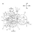
図1は、本発明のギヤ構造体の第1実施形態が備えられるシート製造装置の一部切欠平面図を示す。図2は、図1のA−A線に沿う断面図を示す。図3は、1対のギヤの分解斜視図を示す。図4は、1対のギヤの噛み合いを説明する側断面図を示す。図5は、供給部、ギヤ構造体およびシート調整部の側断面図であり、図1のB−B線に沿う断面図を示す。図6は、第1ギヤを第2ケーシングの上側面から見たときの展開図を示す。
<First Embodiment>
FIG. 1 is a partially cutaway plan view of a sheet manufacturing apparatus provided with a first embodiment of a gear structure of the present invention. FIG. 2 is a sectional view taken along the line AA in FIG. FIG. 3 shows an exploded perspective view of a pair of gears. FIG. 4 is a side sectional view for explaining the meshing of the pair of gears. FIG. 5 is a side cross-sectional view of the supply unit, the gear structure, and the seat adjustment unit, and shows a cross-sectional view along the line BB in FIG. FIG. 6 is a development view when the first gear is viewed from the upper surface of the second casing.
図1において、紙面右側を「右側」、紙面左側を「左側」、紙面下側を「前側」、紙面上側を「後側」として、方向矢印で示し、また、紙面手前側を「上側」、紙面奥側を「下側」として説明する。また、図1において、右側は、1対のギヤ(後述)の回転軸線方向一方側であり、左側は、回転軸線方向他方側であり、前側は、交差方向(後述)一方側であり、後側は、交差方向他方側である。さらに、図2以降の図面の方向については、図1で説明する方向に準じる。 In FIG. 1, the right side of the page is “right side”, the left side of the page is “left side”, the lower side of the page is “front side”, the upper side of the page is “rear side”, and is indicated by a directional arrow. The description will be made assuming that the back side of the page is the “lower side”. Further, in FIG. 1, the right side is one side in the rotation axis direction of a pair of gears (described later), the left side is the other side in the rotation axis direction, the front side is one side in the intersecting direction (described later), and the rear The side is the other side in the cross direction. Further, the directions of the drawings after FIG. 2 are the same as those described in FIG.
図1において、シート製造装置1は、後述する粒子と樹脂成分とを含有する組成物からシート7を製造するように構成されており、例えば、平面視略L字形状に形成されている。シート製造装置1は、混練押出機2と、供給部3と、ギヤ構造体4と、シート調整部5と、巻取部6とを備えている。混練押出機2と供給部3とギヤ構造体4とシート調整部5と巻取部6とは、シート製造装置1において、平面視略L字形状に整列配置されている。つまり、シート製造装置1は、後述する組成物またはシート7(図2参照)を平面視略L字形状に搬送するように、構成されている。
In FIG. 1, the
混練押出機2は、シート製造装置1の左側に設けられている。混練押出機2は、例えば、2軸ニーダーなどであって、具体的には、シリンダ11と、シリンダ11内に収容される混練スクリュー12とを備えている。
The kneading extruder 2 is provided on the left side of the
シリンダ11は、軸線が左右方向に延びる略円筒形状にされている。また、シリンダ11の左方は閉塞されている。
The
図2に示すように、シリンダ11の左端部の上壁には、上方に開口する混練機入口14が形成されている。混練機入口14には、ホッパ16が接続されている。
As shown in FIG. 2, a
シリンダ11の右端部には、右方に開口する混練機出口15が形成されている。混練機出口15には、連結管17が接続されている。
A
なお、シリンダ11には、図示しないブロックヒータが左右方向に沿って複数分割して設けられている。
The
連結管17は、シリンダ11の軸線と共通する軸線を有する略円筒形状に形成されている。
The connecting
混練スクリュー12は、シリンダ11の軸線に平行する回転軸線を有している。混練スクリュー12は、シリンダ11内において、左右方向に沿って設けられている。
The kneading
なお、混練押出機2には、シリンダ11の左側において、混練スクリュー12に接続されるモータ(図示せず)が設けられている。
The kneading extruder 2 is provided with a motor (not shown) connected to the kneading
これによって、混練押出機2は、粒子と樹脂成分とを混練押出するように構成されている。 Thereby, the kneading extruder 2 is configured to knead and extrude the particles and the resin component.
図1に示すように、供給部3は、混練押出機2の右側に設けられており、左右方向に延びるように形成されている。供給部3は、図5に示すように、第1ケーシング21と、供給スクリュー22とを備えている。
As shown in FIG. 1, the
第1ケーシング21は、図1に示すように、左右方向に延びる平面視矩形状をなし、前側が左右方向にわたって開口されている。第1ケーシング21の左端部には、供給部入口18が形成され、第1ケーシング21の前端部には、第1貯留部27が形成されている。また、図5に示すように、第1ケーシング21には、次に説明する供給スクリュー22を収容する第1収容部19が設けられている。第1収容部19は、後部29と、後部29の前側に連通する前部30とを備えている。後部29および前部30のそれぞれは、側断面視略円形状をなし、第1ケーシング21において、左右方向にわたって形成されている。
As shown in FIG. 1, the
供給部入口18は、図1および図5において、第1収容部19(後部29および前部30)に連通している。
In FIG. 1 and FIG. 5, the supply unit inlet 18 communicates with the first storage unit 19 (
第1貯留部27は、前方に向かって大きくなる側断面視略テーパ形状に形成されている。また、第1貯留部27は、後述する密閉空間74に対する搬送方向上流側の上流空間とされる。
The
供給スクリュー22は、第1収容部19に収容されており、左右方向に延び、互いに噛み合う第1スクリュー23および第2スクリュー24を備えている。
The
第1スクリュー23は、後部29内に収容されており、第1スクリュー23と回転方向R1に対して傾斜する羽根20を備えている。第1スクリュー23の羽根20の回転軸線方向におけるピッチ間隔は、例えば、5mm以上、好ましくは、10mm以上であり、また、例えば、50mm以下、好ましくは、30mm以下でもある。
The
第2スクリュー24は、前部30内に収容されており、第1スクリュー23と同一構成および同一寸法であり、第1スクリュー23と噛み合いながら、第1スクリュー23と同一方向に回転するように、構成されている。
The
供給スクリュー22(第1スクリュー23および第2スクリュー24)の回転軸方向の長さは、図1において、第1ケーシング21の幅W0に対して微小なクリアランス(図示せず)の分だけ短く設定されている。
The length of the supply screw 22 (the
なお、供給部3には、第1ケーシング21の右側において、供給スクリュー22に接続されるモータ(図示せず)が設けられている。
The
供給部3は、組成物を、混練押出機2の押出方向(左右方向)に沿う幅W0(つまり、第1ケーシング21の幅W0)を有するように、後方からギヤ構造体4に供給するように構成されている。
The
ギヤ構造体4は、図5に示すように、第2ケーシング31と、1対のギヤ32とを備えている。なお、図1に示すように、ギヤ構造体4は、1対のギヤ32の回転軸線方向A1の長さW2が長く、供給部3から供給される組成物をシート調整部5に搬送するギヤポンプでもある。
As shown in FIG. 5, the gear structure 4 includes a
第2ケーシング31は、図5に示すように、第1ケーシング21の前側に連続して形成されており、後方および前方が左右方向にわたって開口され、左右方向に延びる平面視略矩形状に形成されている。第2ケーシング31の後端部には、1対のギヤ32を収容する第2収容部40が設けられ、前端部には、吐出口46が形成されている。また、第2収容部40と吐出口46との間には、それらに連通する第2貯留部28および吐出通路44が形成されている。
As shown in FIG. 5, the
第2収容部40は、下部61と、下部61の上側に連通する上部62とを備えている。
The
また、下部61の上側面(内側面)71、および、上部62の下側面(内側面)72は、円弧面状(2分割された半円周面状)に形成され、1対のギヤ32を収容する収容空間73を区画する。収容空間73は、第1貯留部27に連通し、断面視において上下に方向に延びるように形成されている。なお、下部61および上部62は、第2ケーシング31において、左右方向にわたって形成されている。また、収容空間73の上端部および下端部には、後述する密閉空間74が設けられる。
Further, the upper side surface (inner side surface) 71 of the
吐出口46は、上下方向に互いに間隔を隔てて形成される2つの吐出壁45によって区画されており、前方に開口されるように形成されている。吐出壁45は、第2ケーシング31の前端部に設けられており、下側壁47および上側壁48を備えている。
The
下側壁47は、左右方向および上下方向に延びる厚肉平板形状をなし、その前面および上面のそれぞれが、平坦状に形成されている。
The
上側壁48は、下面が平坦状に形成されている。また、上側壁48は、側断面視略L字形状をなし、下部の前端部が上部の前面に対して前方に突出するように形成されている。つまり、上側壁48において、下部の前端部が、側断面視略矩形状のドクターとしての突出部63とされている。突出部63の突出長さ(つまり、前後方向長さ)は、例えば、2mm以上であり、また、例えば、150mm以下、好ましくは、50mm以下でもある。また、突出部63の厚み(つまり、上下方向長さ)は、例えば、2mm以上であり、また、例えば、100mm以下、好ましくは、50mm以下でもある。突出部63の前面と、下側壁47の前面とは、上下方向に投影したときに、同一位置となるように、形成されている。
The
第2貯留部28は、第2収容部40の前側に連通しており、後方が開放される側断面視略U字形状に形成されている。また、第2貯留部28は、後述する密閉空間74に対する搬送方向下流側の下流空間とされる。
The
吐出通路44は、第2貯留部28の前側に連通するとともに、吐出口46の後側に連通している。吐出通路44は、側断面視において、前方に向かって延びる略直線状に形成されている。
The
図3に示すように、1対のギヤ32は、例えば、ダブルヘリカルギヤであって、具体的には、第1ギヤ33および第2ギヤ34を備えている。
As shown in FIG. 3, the pair of
第1ギヤ33の回転軸である第1軸25は、第2ケーシング31(図5参照)において、左右方向に延び、回転自在となるように設けられている。
The
第2ギヤ34の回転軸である第2軸26は、第2ケーシング31(図5参照)において、第1軸25と平行して延び、回転自在となるように設けられている。また、第2軸26は、第1軸25に対して上方に対向配置されている。
The
第1ギヤ33および第2ギヤ34のそれぞれは、下部61および上部62に収容されている。また、第1ギヤ33の下半分部分における径方向端部は、下部61の上側面71(後述)に嵌合されるとともに、第2ギヤ34の上半分部分における径方向端部は、上部62の下側面72に嵌合される。
Each of the
第1軸25から上側面71に投影したときの投影面のうち、前側面と第1軸25とを結ぶ線分83と、投影面の後側面と第1軸25とを結ぶ線分84と成す角度α(重複角)は、例えば、30度以上、好ましくは、45度以上であり、また、例えば、180度以下でもある。
Of the projection surface when projected from the
そして、第1ギヤ33および第2ギヤ34のそれぞれは、具体的には、互いに噛み合う斜歯35を備えている。
Each of the
第1ギヤ33において、斜歯35の歯筋は、第1ギヤ33の回転方向R2の下流側から回転方向R2の上流側に向かうに従って、回転軸線方向A1の外側に傾斜している。また、斜歯35は、歯筋が互いに異なる第1下斜歯36および第2下斜歯37を一体的に備えている。第1ギヤ33において、第1下斜歯36は、第1ギヤ33の軸線方向中央に対して右側に形成され、第2下斜歯37は、第1下斜歯36の軸線方向中央に対して左側に形成されている。
In the
詳しくは、第1下斜歯36の歯筋は、回転方向R2の下流側から回転方向R2の上流側に向かうに従って、左側(中央部側)から右側(右端部側)に傾斜している。一方、第2下斜歯37の歯筋は、第1下斜歯36の歯筋に対して第1ギヤ33の左右方向中央部を基準として左右対称に形成されており、具体的には、回転方向R2の下流側から回転方向R2の上流側に向かうに従って、右側(中央部側)から左側(左端部側)に傾斜している。
Specifically, the tooth traces of the first lower
第2ギヤ34は、第1ギヤ33に対して上下対称に形成されており、第1ギヤ33と噛み合うように構成されており、具体的には、第1下斜歯36と噛み合う第1上斜歯38と、第2下斜歯37と噛み合う第2上斜歯39とを一体的に備えている。
The
図4に示すように、1対のギヤ32は、黒丸で示される噛み合い部分が、側断面視において、第1ギヤ33および第2ギヤ34が点状に接触するように構成されることから、側断面点接触タイプとされている。また、1対のギヤ32は、噛み合い部分が、1対のギヤ32の歯筋に沿って、第1ギヤ33および第2ギヤ34の弦巻(つるまき)線状に形成されることから、線接触タイプともされる。
As shown in FIG. 4, the pair of
1対のギヤ32のそれぞれの斜歯35は、回転方向R2において間隔を隔てて設けられ、径方向内方に湾曲するように形成される凹面42と、各凹面42を連結し、凹面42の周方向両端部から径方向外方に湾曲するように形成される凸面43とを一体的に備える曲面41を備えている。
The
また、斜歯35の歯筋間、つまり、凸面43の頂点間には、凹面42を含む歯溝75が形成されている。
Further, a
また、図5に示すように、第2ケーシング31には、1対のギヤ32を、第1ギヤ33の斜歯35と下部61の上側面71との間、および、第2ギヤ34の斜歯35と上部62の下側面72との間に密閉空間74が形成されるように、収容する収容空間73が設けられている。
Further, as shown in FIG. 5, the
つまり、上側面71および下側面72は、1対のギヤ32の直径と同一の曲率を有する断面視円弧状に形成されており、1対のギヤ32の径方向端部(凸面32の頂点、図4参照。)の回転軌跡と同一の断面視略円弧状に形成されている。これによって、密閉空間74は、斜歯35の歯筋間の歯溝75を、上側面71および下側面72によって、被覆する。
That is, the
また、密閉空間74は、上記した重複角αを満足する歯溝75と、上側面71および下側面72とによって、区画される。
Further, the sealed
そして、この1対のギヤ32は、第1貯留部27と、第2貯留部28とが、斜歯35の歯筋間の歯溝75を介して連通しないように、前記1対のギヤが構成されている。
The pair of
図3および図6に示すように、第1下斜歯36の歯溝75、および、第2下斜歯37の歯溝75は、それぞれ互いに連通する。また、第1下斜歯36の歯溝75、および、第1下斜歯36の歯溝75には、回転軸線方向A1の全てにわたって、回転軸線A1から径方向に投影したときに、密閉空間74の内側面、つまり、上側面71(図5参照)と重複する複数(2つ)の重複歯溝76が形成される。
As shown in FIGS. 3 and 6, the
重複歯溝76のうち、最前側(最下流側)の重複歯溝76Aでは、第1下斜歯36の左端部および第2下斜歯37の右端部(つまり、第1ギヤ33の左右方向中央部、つまり、それらの連絡部分)が、上側面71(図5参照)の前端部(回転方向下流側端部)に対向配置されるときには、対応する第1下斜歯36の右端部および第2下斜歯37の左端部(つまり、第1ギヤ33の左右方向両端部)は、第1貯留部27(図5参照)に臨むことなく、上側面71の前後方向(回転方向)途中に対向配置される。
Among the overlapping
また、重複歯溝76のうち、最後側(最上流側)の重複歯溝76Bでは、第1下斜歯36の右端部および第2下斜歯37の左端部(つまり、第1ギヤ33の左右方向両端部)が、上側面71(図5参照)の後端部(回転方向上流側端部)に対向配置されるときには、対応する第1下斜歯36の左端部および第2下斜歯37の右端部(つまり、第1ギヤ33の左右方向中央部、つまり、連絡部分)は、第2貯留部28に臨むことなく、上側面71の前後方向(回転方向)途中に対向配置される。
Of the overlapping
そして、これら複数の重複歯溝76は、第1ギヤ33の回転によって、その回転方向上流側に向かう歯溝75へと移行する。
The plurality of overlapping
また、第2ギヤ34の重複歯溝76および下側面72は、第1ギヤ33の重複歯溝76および上側面71と同様の構成であり、具体的には、噛み合い部分に対して上下対称の構成とされる。すなわち、歯溝75には、下側面72と重複する重複歯溝76が複数形成される。重複歯溝76は、第2ギヤ34の回転によって、回転方向上流側に向かう歯溝75へと移行する。
Further, the overlapping
なお、ギヤ構造体4には、供給スクリュー22の右側において、1対のギヤ32の第1軸25および第2軸26に接続されるモータ(図示せず)が設けられている。
The gear structure 4 is provided with a motor (not shown) connected to the
次に、1対のギヤ32の曲面41における噛み合いを図4(a)〜図4(c)を参照して説明する。
Next, the meshing of the pair of
まず、図4(a)に示すように、第1ギヤ33の凸面43の回転方向R2の下流側端部と、第2ギヤ34の凹面42の回転方向R2の下流側端部とが噛み合っている場合において、図4(a)矢印および図4(b)に示すように、第1ギヤ33および第2ギヤ34が回転方向R2に回転すると、第1ギヤ33の凸面43の回転方向R2の途中部と、第2ギヤ34の凹面42の回転方向R2の途中部とが噛み合う。続いて、図4(b)矢印および図4(c)に示すように、第1ギヤ33および第2ギヤ34が回転方向R2に回転すると、第1ギヤ33の凸面43の回転方向R2の上流側端部と、第2ギヤ34の凹面42の回転方向R2の上流側端部とが噛み合う。つまり、第1ギヤ33の凸面43と、第2ギヤ34の凹面42との噛合部分が、各面における回転方向R2の下流側端部、途中部および上流側端部に順次連続的に移動する。
First, as shown in FIG. 4A, the downstream end portion of the
続いて、図示しないが、第1ギヤ33の凹面42と、第2ギヤ34の凸面43との噛合部分も、各面における回転方向R2の下流側端部、途中部および上流側端部に順次連続的に移動する。
Subsequently, although not shown, the meshing portions of the
従って、第1ギヤ33の曲面41と、第2ギヤ34の曲面41との噛合部分が、回転方向R2に沿って連続して移動する。この噛合部分の移動は、組成物の搬送において、組成物が溜まる貯留部分が歯筋間の歯溝75に形成されることを防止する。
Therefore, the meshing portion of the
シート調整部5は、図1および図5に示すように、ギヤ構造体4の前側において上側壁48の突出部63を含むように設けられており、例えば、ギヤ構造体4における突出部63と、支持ロール51とを備えている。また、シート調整部5は、図2に示すように、基材送出ロール56と、セパレータラミネートロール57と、転動ロール58と、セパレータ送出ロール59とを備えている。
As shown in FIGS. 1 and 5, the
突出部63は、図5に示すように、ギヤ構造体4における第2ケーシング31の吐出口46を区画する壁の役割と、シート調整部5における吐出口46から吐出される組成物の厚みを調整するドクター(あるいはナイフ)の役割との両方の役割を有する。
As shown in FIG. 5, the
支持ロール51は、突出部63に対して隙間50が設けられるように対向配置されている。支持ロール51の回転軸線は、1対のギヤ32の第1軸25および第2軸26と平行しており、具体的には、左右方向に延びている。また、支持ロール51の回転軸線は、前後方向に投影したときに、吐出口46および突出部63と重なるように、配置されている。また、支持ロール51は、組成物を支持して搬送するように構成されている。
The
従って、支持ロール51は、組成物を隙間50に通過させるように構成されている。
Therefore, the
図2に示すように、基材送出ロール56は、支持ロール51の下方に間隔を隔てて設けられている。基材送出ロール56の回転軸線は、左右方向に延びており、基材送出ロール56の周面には、基材8がロール状に巻回されている。
As shown in FIG. 2, the base
セパレータラミネートロール57および転動ロール58は、支持ロール51の前方に間隔を隔てて設けられている。セパレータラミネートロール57および転動ロール58のそれぞれの回転軸線は、左右方向に延びるように配置されている。セパレータラミネートロール57は、転動ロール58に対して上側に対向配置されており、転動ロール58に対して押圧可能に構成されている。
The
転動ロール58は、セパレータラミネートロール57からの押圧を受けて、シート7および基材8に対して転動可能に構成されており、その上端部は、前後方向に投影したときに、支持ロール51の上端部と同一位置となるように、配置されている。
The rolling
セパレータ送出ロール59は、セパレータラミネートロール57の前方斜め上側に間隔を隔てて設けられている。セパレータ送出ロール59の回転軸線は、左右方向に延びており、セパレータ送出ロール59の周面には、セパレータ9がロール状に巻回されている。
The
巻取部6は、シート調整部5の前方に設けられており、テンションロール52と、巻取ロール53とを備えている。
The winding unit 6 is provided in front of the
テンションロール52は、転動ロール58の前方に間隔を隔てて設けられ、具体的には、テンションロール52の上端部は、前後方向に投影したときに、転動ロール58の上端部と同一位置となるように、配置されている。テンションロール52の回転軸線は、左右方向に延びるように形成されている。
The
巻取ロール53は、テンションロール52に対して前方斜め下側に間隔を隔てて対向配置されている。また、巻取ロール53の回転軸線は、左右方向に延びており、巻取ロール53の周面において、積層シート10をロール状に巻き取ることができるように、構成されている。
The take-
シート製造装置1の寸法は、用いる粒子および樹脂成分の種類および配合割合と、目的とするシート7の幅W1および厚みT1に対応して適宜設定される。
The dimensions of the
図1に示すように、第1ケーシング21の幅W0は、例えば、1対のギヤ32の回転軸線方向長さW2と下記式(1)の関係、好ましくは、下記式(2)の関係、より好ましくは、下記式(3)の関係を満足するように、設定される。
As shown in FIG. 1, the width W0 of the
W2−100(mm)≦W0≦W2+150(mm) (1)
W2−50(mm) ≦W0≦W2+100(mm) (2)
W2−20(mm) ≦W0≦W2+50(mm) (3)
1対のギヤ32の回転軸線方向長さW2は、製造するシート7の幅W1によって適宜選択することができ、具体的には、上記した第1ケーシング21の幅W0と同様であって、シート7の幅W1に対して、例えば、70%以上、好ましくは、80%以上であり、また、例えば、100%以下でもある。
W2-100 (mm) ≦ W0 ≦ W2 + 150 (mm) (1)
W2-50 (mm) ≦ W0 ≦ W2 + 100 (mm) (2)
W2-20 (mm) ≦ W0 ≦ W2 + 50 (mm) (3)
The length W2 of the pair of
図5に示すように、1対のギヤ32の回転軌跡において、第1ギヤ33と上側面71とが対向する回転方向長さL2(図6参照)、および、第2ギヤ34と下側面72とが対向する回転方向長さ(図6において図示せず)は、例えば、2mm以上、好ましくは、3mm以上、好ましくは、5mm以上であり、また、例えば、324mm以下、好ましくは、315mm以下でもある。上記した長さが上記下限以上であれば、複数の重複歯溝76を確実に形成して、シート7の搬送効率を向上させることができる。一方、上記した長さが上記上限以下であれば、組成物の搬送効率を向上させることができる。
As shown in FIG. 5, in the rotation trajectory of the pair of
図3に示すように、1対のギヤ32の回転軸線方向長さW2は、例えば、200mm以上、好ましくは、300mm以上であり、また、例えば、2000mm以下でもある。
As shown in FIG. 3, the length W2 of the pair of
1対のギヤ32のギヤ径(ギヤ32の直径(外径)、詳しくは、刃先円の直径)は、組成物の搬送時の圧力で1対のギヤ32が歪まないように設定され、例えば、10mm以上、好ましくは、20mm以上であり、また、例えば、200mm以下、好ましくは、80mm以下でもある。また、1対のギヤ32の歯底円の直径(ギヤ径から次に説明する歯たけL3の2倍値(L3×2)を差し引いた値)は、例えば、8mm以上、好ましくは、10mm以上であり、また、例えば、198mm以下、好ましくは、194mm以下でもある。
The gear diameter of the pair of gears 32 (the diameter (outer diameter) of the
図4に示すように、1対のギヤ32の歯たけL3は、例えば、1mm以上、好ましくは、3mm以上であり、また、例えば、30mm以下、好ましくは、20mm以下でもある。
As shown in FIG. 4, the tooth depth L3 of the pair of
斜歯35の回転軸線方向A1におけるピッチ間隔は、例えば、5mm以上、好ましくは、10mm以上であり、また、例えば、30mm以下、好ましくは、25mm以下でもある。また、斜歯35の歯筋の、1対のギヤ32の回転軸線に対する角度(傾斜角)は、例えば、0度を超過し、好ましくは、5度以上、より好ましくは、15度以上であり、また、例えば、75度未満、好ましくは、70度以下、より好ましくは、60度以下でもある。傾斜角が上記下限以上であれば、組成物を回転軸線A1の両外側に広げて、幅広のシート7を確実に形成することができる。一方、傾斜角が上記上限以下であれば、重複歯溝76を確実に形成して、シート7の搬送効率を向上させることができる。
The pitch interval of the
また、図5に示すように、隙間50の前後方向距離は、吐出口46の寸法に応じて適宜設定され、例えば、10μm以上、好ましくは、30μm以上であり、また、例えば、1000μm以下、好ましくは、800μm以下でもある。
As shown in FIG. 5, the distance in the front-rear direction of the
以下、このシート製造装置1を用いて、粒子と樹脂成分とを含有する組成物からシート7を製造する方法について説明する。
Hereinafter, a method for manufacturing the sheet 7 from a composition containing particles and a resin component using the
粒子は、粉体、粒体、粉粒体、粉末を含んでおり、粒子を形成する材料としては、例えば、無機材料、有機材料などが挙げられる。好ましくは、無機材料が挙げられる。 The particles include powder, granules, powders, and powders, and examples of the material forming the particles include inorganic materials and organic materials. Preferably, an inorganic material is used.
無機材料としては、例えば、炭化物、窒化物、酸化物、炭酸塩、硫酸塩、金属、粘土鉱物、炭素系材料などが挙げられる。 Examples of the inorganic material include carbide, nitride, oxide, carbonate, sulfate, metal, clay mineral, and carbon-based material.
炭化物としては、例えば、炭化ケイ素、炭化ホウ素、炭化アルミニウム、炭化チタン、炭化タングステンなどが挙げられる。 Examples of the carbide include silicon carbide, boron carbide, aluminum carbide, titanium carbide, and tungsten carbide.
窒化物としては、例えば、窒化ケイ素、窒化ホウ素(BN)、窒化アルミニウム(AlN)、窒化ガリウム、窒化クロム、窒化タングステン、窒化マグネシウム、窒化モリブデン、窒化リチウムなどが挙げられる。 Examples of the nitride include silicon nitride, boron nitride (BN), aluminum nitride (AlN), gallium nitride, chromium nitride, tungsten nitride, magnesium nitride, molybdenum nitride, and lithium nitride.
酸化物としては、例えば、酸化ケイ素(シリカ。球状溶融シリカ粉末、破砕溶融シリカ粉末などを含む。)、酸化アルミニウム(アルミナ、Al2O3)、酸化マグネシウム(マグネシア)、酸化チタン、酸化セリウム、酸化鉄、酸化ベリリウムなどが挙げられる。さらに、酸化物として、金属イオンがドーピングされている、例えば、酸化インジウムスズ、酸化アンチモンスズが挙げられる。 Examples of the oxide include silicon oxide (silica, including spherical fused silica powder, crushed fused silica powder, etc.), aluminum oxide (alumina, Al 2 O 3 ), magnesium oxide (magnesia), titanium oxide, cerium oxide, Examples thereof include iron oxide and beryllium oxide. Furthermore, as the oxide, for example, indium tin oxide or antimony tin oxide doped with metal ions can be used.
炭酸塩としては、例えば、炭酸カルシウムなどが挙げられる。 Examples of the carbonate include calcium carbonate.
硫酸塩としては、例えば、硫酸カルシウム(石膏)などが挙げられる。 Examples of the sulfate include calcium sulfate (gypsum).
金属としては、例えば、銅(Cu)、銀、金、ニッケル、クロム、鉛、亜鉛、錫、鉄、パラジウム、または、それらの合金(はんだなど)が挙げられる。 Examples of the metal include copper (Cu), silver, gold, nickel, chromium, lead, zinc, tin, iron, palladium, or an alloy thereof (such as solder).
粘土鉱物としては、例えば、モンモリロン石、マグネシアンモンモリロン石、テツモンモリロン石、テツマグネシアンモンモリロン石、バイデライト、アルミニアンバイデライト、ノントロン石、アルミニアンノントロナイト、サポー石、アルミニアンサポー石、ヘクトライト、ソーコナイト、スチーブンサイトなどが挙げられる。 Examples of clay minerals include montmorillonite, magnesia montmorillonite, tetsu montmorillonite, tetsu magnesian montmorillonite, beidellite, aluminian beidelite, nontronite, aluminian nontronite, support stone, aluminian support stone, Examples include hectorite, soconite, and stevensite.
炭素系材料としては、例えば、カーボンブラック、黒鉛、ダイヤモンド、フラーレン、カーボンナノチューブ、カーボンナノファイバー、ナノホーン、カーボンマイクロコイル、ナノコイルなどが挙げられる。 Examples of the carbon-based material include carbon black, graphite, diamond, fullerene, carbon nanotube, carbon nanofiber, nanohorn, carbon microcoil, and nanocoil.
また、材料として、特定物性を有する材料も挙げられ、熱伝導性材料(例えば、炭化物、窒化物、酸化物および金属から選択される熱伝導性材料、具体的には、BN、AlN、Al2O3など)、電気伝導性材料(例えば、金属、炭素系材料から選択される電気伝導性材料、具体的には、Cuなど)、絶縁材料(例えば、窒化物、酸化物など、具体的には、BN、シリカなど)、磁性材料(例えば、酸化物、金属、具体的には、フェライト(軟質磁性フェライト、硬質磁性)、鉄など)なども挙げられる。特定物性を有する材料は、上記で例示した材料と重複してもよい。 In addition, examples of the material include a material having specific physical properties, and a heat conductive material (for example, a heat conductive material selected from carbide, nitride, oxide and metal, specifically, BN, AlN, Al 2). O 3 ), an electrically conductive material (for example, an electrically conductive material selected from metals and carbon-based materials, specifically Cu), an insulating material (for example, nitride, oxide, etc.) BN, silica, etc.), magnetic materials (for example, oxides, metals, specifically, ferrites (soft magnetic ferrite, hard magnetic), iron, etc.). The material having specific physical properties may overlap with the material exemplified above.
なお、熱伝導性材料の熱伝導率は、例えば、10W/m・K以上、好ましくは、30W/m・K以上であり、また、例えば、2000W/m・K以下でもある。 The thermal conductivity of the heat conductive material is, for example, 10 W / m · K or more, preferably 30 W / m · K or more, and for example, 2000 W / m · K or less.
また、電気伝導性材料の電気伝導率は、例えば、106S/m以上、好ましくは、108S/m以上、通常、1010S/m以下である。 Further, the electrical conductivity of the electrically conductive material is, for example, 10 6 S / m or more, preferably 10 8 S / m or more, and usually 10 10 S / m or less.
また、絶縁材料の体積抵抗は、1×10¹⁰Ω・cm以上、好ましくは、1×10¹²Ω・cm以上であり、また、例えば、1×10²⁰Ω・cm以下でもある。 The volume resistance of the insulating material is 1 × 10 10 Ω · cm or more, preferably 1 × 10 12 Ω · cm or more, and for example, 1 × 10 20 Ω · cm or less.
また、磁性材料の透磁率(波長2.45GHzにおけるμ’’)は、例えば、0.1〜10である。 The magnetic material has a magnetic permeability (μ ″ at a wavelength of 2.45 GHz), for example, 0.1 to 10.
また、粒子の形状は、特に限定されず、例えば、板状、鱗片状、粒子状(不定形状)、球形状などが挙げられる。 Moreover, the shape of particle | grains is not specifically limited, For example, plate shape, scale shape, particle shape (indefinite shape), spherical shape etc. are mentioned.
粒子の最大長さの平均値(球形状である場合には、平均粒子径)は、例えば、0.1μm以上、好ましくは、1μm以上であり、また、例えば、1000μm以下、好ましくは、100μm以下でもある。 The average value of the maximum length of particles (in the case of a spherical shape, the average particle diameter) is, for example, 0.1 μm or more, preferably 1 μm or more, and, for example, 1000 μm or less, preferably 100 μm or less. But there is.
また、粒子のアスペクト比は、例えば、2以上、好ましくは、10以上であり、また、例えば、10000以下、好ましくは、5000以下でもある。 The aspect ratio of the particles is, for example, 2 or more, preferably 10 or more, and is, for example, 10,000 or less, preferably 5000 or less.
また、粒子の比重は、例えば、0.1g/cm3以上、好ましくは、0.2g/cm3以上であり、また、例えば、20g/cm3以下、好ましくは、10g/cm3以下でもある。 The specific gravity of the particles is, for example, 0.1 g / cm 3 or more, preferably 0.2 g / cm 3 or more, and for example, 20 g / cm 3 or less, preferably 10 g / cm 3 or less. .
これら粒子は、単独使用または2種類以上併用することができる。 These particles can be used alone or in combination of two or more.
樹脂成分は、粒子を分散できるもの、つまり、粒子が分散される分散媒体(マトリックス)であって、絶縁成分を含有し、例えば、熱硬化性樹脂成分、熱可塑性樹脂成分などの樹脂成分が挙げられる。 The resin component can disperse the particles, that is, a dispersion medium (matrix) in which the particles are dispersed and contains an insulating component, and examples thereof include resin components such as a thermosetting resin component and a thermoplastic resin component. It is done.
熱硬化性樹脂成分としては、例えば、エポキシ樹脂、熱硬化性ポリイミド、ユリア樹脂、メラミン樹脂、不飽和ポリエステル樹脂、ジアリルフタレート樹脂、シリコーン樹脂、熱硬化性ウレタン樹脂などが挙げられる。 Examples of the thermosetting resin component include epoxy resins, thermosetting polyimides, urea resins, melamine resins, unsaturated polyester resins, diallyl phthalate resins, silicone resins, thermosetting urethane resins, and the like.
熱可塑性樹脂成分としては、例えば、アクリル樹脂、ポリオレフィン(例えば、ポリエチレン、ポリプロピレン、エチレン−プロピレン共重合体など)、ポリ酢酸ビニル、エチレン−酢酸ビニル共重合体、ポリ塩化ビニル、ポリスチレン、ポリアクリロニトリル、ポリアミド、ポリカーボネート、ポリアセタール、ポリエチレンテレフタレート、ポリフェニレンオキシド、ポリフェニレンスルフィド、ポリスルホン、ポリエーテルスルホン、ポリエーテルエーテルケトン、ポリアリルスルホン、熱可塑性ポリイミド、熱可塑性ウレタン樹脂、ポリアミノビスマレイミド、ポリアミドイミド、ポリエーテルイミド、ビスマレイミドトリアジン樹脂、ポリメチルペンテン、フッ化樹脂、液晶ポリマー、オレフィン−ビニルアルコール共重合体、アイオノマー、ポリアリレート、アクリロニトリル−エチレン−スチレン共重合体、アクリロニトリル−ブタジエン−スチレン共重合体、アクリロニトリル−スチレン共重合体などが挙げられる。 Examples of the thermoplastic resin component include acrylic resin, polyolefin (for example, polyethylene, polypropylene, ethylene-propylene copolymer, etc.), polyvinyl acetate, ethylene-vinyl acetate copolymer, polyvinyl chloride, polystyrene, polyacrylonitrile, Polyamide, polycarbonate, polyacetal, polyethylene terephthalate, polyphenylene oxide, polyphenylene sulfide, polysulfone, polyethersulfone, polyetheretherketone, polyallylsulfone, thermoplastic polyimide, thermoplastic urethane resin, polyaminobismaleimide, polyamideimide, polyetherimide, Bismaleimide triazine resin, polymethylpentene, fluororesin, liquid crystal polymer, olefin-vinyl alcohol copolymer, polymer Ionomer, polyarylate, acrylonitrile - ethylene - styrene copolymers, acrylonitrile - butadiene - styrene copolymer, acrylonitrile - styrene copolymer.
これら樹脂成分は、単独使用または2種類以上併用することができる。 These resin components can be used alone or in combination of two or more.
樹脂成分のうち、熱硬化性樹脂成分として、好ましくは、エポキシ樹脂が挙げられ、また、熱可塑性樹脂成分として、好ましくは、アクリル樹脂が挙げられる。 Among the resin components, the thermosetting resin component is preferably an epoxy resin, and the thermoplastic resin component is preferably an acrylic resin.
エポキシ樹脂は、常温において、液状、半固形状および固形状のいずれかの形態である。 The epoxy resin is in a liquid, semi-solid, or solid form at normal temperature.
具体的には、エポキシ樹脂としては、例えば、ビスフェノール型エポキシ樹脂(例えば、ビスフェノールA型エポキシ樹脂、ビスフェノールF型エポキシ樹脂、ビスフェノールS型エポキシ樹脂、水素添加ビスフェノールA型エポキシ樹脂、ダイマー酸変性ビスフェノール型エポキシ樹脂など)、ノボラック型エポキシ樹脂、ナフタレン型エポキシ樹脂、フルオレン型エポキシ樹脂(例えば、ビスアリールフルオレン型エポキシ樹脂など)、トリフェニルメタン型エポキシ樹脂(例えば、トリスヒドロキシフェニルメタン型エポキシ樹脂など)などの芳香族系エポキシ樹脂、例えば、トリエポキシプロピルイソシアヌレート、ヒダントインエポキシ樹脂などの含窒素環エポキシ樹脂、例えば、脂肪族系エポキシ樹脂、脂環式エポキシ樹脂、グリシジルエーテル型エポキシ樹脂、グリシジルアミン型エポキシ樹脂などが挙げられる。 Specifically, as the epoxy resin, for example, bisphenol type epoxy resin (for example, bisphenol A type epoxy resin, bisphenol F type epoxy resin, bisphenol S type epoxy resin, hydrogenated bisphenol A type epoxy resin, dimer acid modified bisphenol type) Epoxy resin, etc.), novolac type epoxy resin, naphthalene type epoxy resin, fluorene type epoxy resin (eg, bisarylfluorene type epoxy resin), triphenylmethane type epoxy resin (eg, trishydroxyphenylmethane type epoxy resin), etc. Aromatic epoxy resins such as nitrogen-containing ring epoxy resins such as triepoxypropyl isocyanurate and hydantoin epoxy resins such as aliphatic epoxy resins, alicyclic epoxy resins, Glycidyl ether type epoxy resins, and glycidyl amine type epoxy resin.
これらエポキシ樹脂は、単独使用または2種以上併用することができる。 These epoxy resins can be used alone or in combination of two or more.
エポキシ樹脂のエポキシ当量は、例えば、例えば、100〜1000g/eq.、好ましくは、180〜700g/eq.である。また、エポキシ樹脂が、常温固形状である場合には、軟化点が、例えば、20〜90℃である。 The epoxy equivalent of the epoxy resin is, for example, 100 to 1000 g / eq. , Preferably 180 to 700 g / eq. It is. Moreover, when an epoxy resin is a normal temperature solid state, a softening point is 20-90 degreeC, for example.
また、エポキシ樹脂には、例えば、硬化剤および硬化促進剤を含有させて、エポキシ樹脂組成物として調製することができる。 Moreover, an epoxy resin can be prepared as an epoxy resin composition by containing a hardening | curing agent and a hardening accelerator, for example.
硬化剤は、加熱によりエポキシ樹脂を硬化させることができる潜在性硬化剤(エポキシ樹脂硬化剤)であって、例えば、フェノール化合物、アミン化合物、酸無水物化合物、アミド化合物、ヒドラジド化合物、イミダゾリン化合物などが挙げられる。また、上記の他に、ユリア化合物、ポリスルフィド化合物なども挙げられる。 The curing agent is a latent curing agent (epoxy resin curing agent) that can cure the epoxy resin by heating. For example, a phenol compound, an amine compound, an acid anhydride compound, an amide compound, a hydrazide compound, an imidazoline compound, and the like. Is mentioned. In addition to the above, urea compounds, polysulfide compounds, and the like are also included.
フェノール化合物は、フェノール樹脂を含み、例えば、フェノールとホルムアルデヒドとを酸性触媒下で縮合させて得られるノボラック型フェノール樹脂、例えば、フェノールとジメトキシパラキシレンまたはビス(メトキシメチル)ビフェニルから合成されるフェノール・アラルキル樹脂、例えば、ビフェニル・アラルキル樹脂、例えば、ジシクロペンタジエン型フェノール樹脂、例えば、クレゾールノボラック樹脂、例えば、レゾール樹脂などが挙げられる。 The phenol compound contains a phenol resin, for example, a novolac-type phenol resin obtained by condensing phenol and formaldehyde in the presence of an acidic catalyst, for example, phenol synthesized from phenol and dimethoxyparaxylene or bis (methoxymethyl) biphenyl. Examples include aralkyl resins such as biphenyl aralkyl resins, such as dicyclopentadiene type phenol resins, such as cresol novolac resins, such as resole resins.
アミン化合物としては、例えば、エチレンジアミン、プロピレンジアミン、ジエチレントリアミン、トリエチレンテトラミンなどのポリアミン、または、これらのアミンアダクトなど、例えば、メタフェニレンジアミン、ジアミノジフェニルメタン、ジアミノジフェニルスルホンなどが挙げられる。 Examples of the amine compound include polyamines such as ethylenediamine, propylenediamine, diethylenetriamine, and triethylenetetramine, or amine adducts thereof such as metaphenylenediamine, diaminodiphenylmethane, and diaminodiphenylsulfone.
酸無水物化合物としては、例えば、無水フタル酸、無水マレイン酸、テトラヒドロフタル酸無水物、ヘキサヒドロフタル酸無水物、4−メチル−ヘキサヒドロフタル酸無水物、メチルナジック酸無水物、ピロメリット酸無水物、ドデセニルコハク酸無水物、ジクロロコハク酸無水物、ベンゾフェノンテトラカルボン酸無水物、クロレンディック酸無水物などが挙げられる。 Examples of the acid anhydride compound include phthalic anhydride, maleic anhydride, tetrahydrophthalic anhydride, hexahydrophthalic anhydride, 4-methyl-hexahydrophthalic anhydride, methyl nadic acid anhydride, and pyromellitic acid. Anhydride, dodecenyl succinic anhydride, dichlorosuccinic anhydride, benzophenone tetracarboxylic acid anhydride, chlorendic acid anhydride and the like can be mentioned.
アミド化合物としては、例えば、ジシアンジアミド、ポリアミドなどが挙げられる。 Examples of the amide compound include dicyandiamide and polyamide.
ヒドラジド化合物としては、例えば、アジピン酸ジヒドラジドなどが挙げられる。 Examples of the hydrazide compound include adipic acid dihydrazide.
イミダゾリン化合物としては、例えば、メチルイミダゾリン、2−エチル−4−メチルイミダゾリン、エチルイミダゾリン、イソプロピルイミダゾリン、2,4−ジメチルイミダゾリン、フェニルイミダゾリン、ウンデシルイミダゾリン、ヘプタデシルイミダゾリン、2−フェニル−4−メチルイミダゾリンなどが挙げられる。 Examples of the imidazoline compound include methyl imidazoline, 2-ethyl-4-methyl imidazoline, ethyl imidazoline, isopropyl imidazoline, 2,4-dimethyl imidazoline, phenyl imidazoline, undecyl imidazoline, heptadecyl imidazoline, 2-phenyl-4-methyl. Examples include imidazoline.
これら硬化剤は、単独使用または2種類以上併用することができる。 These curing agents can be used alone or in combination of two or more.
硬化促進剤は、硬化触媒であって、例えば、2−フェニルイミダゾール、2−メチルイミダゾール、2−エチル−4−メチルイミダゾール、2−フェニル−4−メチル−5−ヒドロキシメチルイミダゾールなどのイミダゾール化合物、例えば、トリエチレンジアミン、トリ−2,4,6−ジメチルアミノメチルフェノールなどの3級アミン化合物、例えば、トリフェニルホスフィン、テトラフェニルホスホニウムテトラフェニルボレート、テトラ−n−ブチルホスホニウム−o,o−ジエチルホスホロジチオエートなどのリン化合物、例えば、4級アンモニウム塩化合物、例えば、有機金属塩化合物、例えば、それらの誘導体などが挙げられる。これら硬化促進剤は、単独使用または2種類以上併用することができる。 The curing accelerator is a curing catalyst, for example, an imidazole compound such as 2-phenylimidazole, 2-methylimidazole, 2-ethyl-4-methylimidazole, 2-phenyl-4-methyl-5-hydroxymethylimidazole, For example, tertiary amine compounds such as triethylenediamine and tri-2,4,6-dimethylaminomethylphenol, such as triphenylphosphine, tetraphenylphosphonium tetraphenylborate, tetra-n-butylphosphonium-o, o-diethylphospho Phosphorus compounds such as rosioate, for example, quaternary ammonium salt compounds, for example, organometallic salt compounds, for example, derivatives thereof and the like. These curing accelerators can be used alone or in combination of two or more.
エポキシ樹脂組成物における硬化剤の配合割合は、エポキシ樹脂100質量部に対して、例えば、0.5〜200質量部、好ましくは、1〜150質量部であり、硬化促進剤の配合割合は、例えば、0.1〜10質量部、好ましくは、0.2〜5質量部である。また、硬化剤がフェノール樹脂を含有する場合には、エポキシ樹脂組成物において、エポキシ樹脂のエポキシ基1モルに対して、フェノール樹脂の水酸基が、例えば、0.5〜2.0モル、好ましくは、0.8〜1.2モルとなるように調整される。 The compounding ratio of the curing agent in the epoxy resin composition is, for example, 0.5 to 200 parts by mass, preferably 1 to 150 parts by mass with respect to 100 parts by mass of the epoxy resin. For example, 0.1 to 10 parts by mass, preferably 0.2 to 5 parts by mass. Moreover, when a hardening | curing agent contains a phenol resin, the hydroxyl group of a phenol resin is 0.5-2.0 mol with respect to 1 mol of epoxy groups of an epoxy resin in an epoxy resin composition, Preferably , 0.8 to 1.2 mol.
上記した硬化剤および/または硬化促進剤は、必要により、溶媒により溶解および/または分散された溶媒溶液および/または溶媒分散液として調製して用いることができる。 The above-mentioned curing agent and / or curing accelerator can be prepared and used as a solvent solution and / or a solvent dispersion dissolved and / or dispersed with a solvent, if necessary.
溶媒としては、例えば、アセトン、メチルエチルケトン(MEK)などケトン、例えば、酢酸エチルなどのエステル、例えば、N,N−ジメチルホルムアミドなどのアミドなどの有機溶媒などが挙げられる。また、溶媒として、例えば、水、例えば、メタノール、エタノール、プロパノール、イソプロパノールなどのアルコールなどの水系溶媒も挙げられる。 Examples of the solvent include organic solvents such as ketones such as acetone and methyl ethyl ketone (MEK), esters such as ethyl acetate, and amides such as N, N-dimethylformamide. Examples of the solvent also include aqueous solvents such as water, for example, alcohols such as methanol, ethanol, propanol, and isopropanol.
アクリル樹脂は、アクリルゴムを含み、具体的には、(メタ)アクリル酸アルキルエステルを含むモノマーの重合により得られる。 The acrylic resin contains acrylic rubber, and is specifically obtained by polymerization of a monomer containing (meth) acrylic acid alkyl ester.
(メタ)アクリル酸アルキルエステルは、メタクリル酸アルキルエステルおよび/また
はアクリル酸アルキルエステルであって、例えば、(メタ)アクリル酸メチル、(メタ)
アクリル酸エチル、(メタ)アクリル酸ブチル、(メタ)アクリル酸ヘキシル、(メタ)
アクリル酸2−エチルヘキシル、(メタ)アクリル酸ノニル、(メタ)アクリル酸イソノニル、(メタ)アクリル酸デシル、(メタ)アクリル酸イソデシル、(メタ)アクリル酸ウンデシル、(メタ)アクリル酸ラウリル、(メタ)アクリル酸トリデシル、(メタ)アクリル酸テトラデシル、(メタ)アクリル酸オクタデシル、(メタ)アクリル酸オクタドデシルなどの、アルキル部分が炭素数30以下の直鎖状または分岐状の(メタ)アクリル酸アルキルエステルが挙げられ、好ましくは、アルキル部分が炭素数1〜18の直鎖状の(メタ)アクリル酸アルキルエステルが挙げられる。
The (meth) acrylic acid alkyl ester is a methacrylic acid alkyl ester and / or an acrylic acid alkyl ester, for example, methyl (meth) acrylate, (meth)
Ethyl acrylate, butyl (meth) acrylate, hexyl (meth) acrylate, (meth)
2-ethylhexyl acrylate, nonyl (meth) acrylate, isononyl (meth) acrylate, decyl (meth) acrylate, isodecyl (meth) acrylate, undecyl (meth) acrylate, lauryl (meth) acrylate, (meth Linear or branched alkyl (meth) acrylates having an alkyl moiety of 30 or less carbon atoms, such as tridecyl acrylate, tetradecyl (meth) acrylate, octadecyl (meth) acrylate, and octadodecyl (meth) acrylate An ester is mentioned, Preferably, the alkyl part has a C1-C18 linear (meth) acrylic-acid alkylester.
これら(メタ)アクリル酸アルキルエステルは、単独使用または2種以上併用することができる。 These alkyl (meth) acrylates can be used alone or in combination of two or more.
(メタ)アクリル酸アルキルエステルの配合割合は、モノマーに対して、例えば、50質量%以上、好ましくは、75質量%以上であり、例えば、99質量%以下でもある。 The blending ratio of the (meth) acrylic acid alkyl ester is, for example, 50% by mass or more, preferably 75% by mass or more, for example, 99% by mass or less with respect to the monomer.
モノマーは、(メタ)アクリル酸アルキルエステルと重合可能な共重合性モノマーを含むこともできる。 The monomer may also include a copolymerizable monomer that can be polymerized with (meth) acrylic acid alkyl ester.
共重合性モノマーは、ビニル基を含有し、例えば、(メタ)アクリロニトリルなどのシアノ基含有ビニルモノマー、例えば、(メタ)アクリル酸グリシジルなどのグリシジル基含有ビニルモノマー(エポキシ基含有ビニルモノマー)例えば、スチレンなどの芳香族ビニルモノマーなどが挙げられる。 The copolymerizable monomer contains a vinyl group, for example, a cyano group-containing vinyl monomer such as (meth) acrylonitrile, for example, a glycidyl group-containing vinyl monomer such as glycidyl (meth) acrylate (epoxy group-containing vinyl monomer), for example, Examples thereof include aromatic vinyl monomers such as styrene.
共重合性モノマーの配合割合は、モノマーに対して、例えば、50質量%以下、好まし
くは、25質量%以下であり、例えば、1質量%以上でもある。
The blending ratio of the copolymerizable monomer is, for example, 50% by mass or less, preferably 25% by mass or less, for example, 1% by mass or more with respect to the monomer.
これら共重合性モノマーは、単独または2種以上併用することができる。 These copolymerizable monomers can be used alone or in combination of two or more.
共重合性モノマーがシアノ基含有ビニルモノマーおよび/またはエポキシ基含有ビニルモノマーである場合には、得られるアクリル樹脂は、主鎖の末端または途中に結合するエポキシ基および/またはシアノ基などの官能基が導入された、官能基変性アクリル樹脂(具体的には、シアノ変性アクリル樹脂、エポキシ変性アクリル樹脂、シアノ・エポキシ変性アクリル樹脂)とされる。 When the copolymerizable monomer is a cyano group-containing vinyl monomer and / or an epoxy group-containing vinyl monomer, the resulting acrylic resin has a functional group such as an epoxy group and / or a cyano group bonded to the terminal or midway of the main chain. Are introduced into the functional group-modified acrylic resin (specifically, cyano-modified acrylic resin, epoxy-modified acrylic resin, cyano-epoxy-modified acrylic resin).
樹脂成分(熱硬化性樹脂成分を含有する場合には、熱硬化性樹脂成分がAステージ状態である樹脂成分)の80℃における溶融粘度は、例えば、10Pa・s以上、好ましくは、50Pa・s以上であり、また、例えば、10000mPa・s以下、好ましくは、10000mPa・s以下でもある。 The melt viscosity at 80 ° C. of the resin component (when the thermosetting resin component is contained, the resin component in which the thermosetting resin component is in an A stage state) is, for example, 10 Pa · s or more, preferably 50 Pa · s. In addition, for example, it is 10000 mPa · s or less, preferably 10000 mPa · s or less.
また、樹脂成分の軟化温度(環球法)は、例えば、80℃以下、好ましくは、70℃以下であり、また、例えば、20℃以上、好ましくは、35℃以上でもある。 The softening temperature (ring and ball method) of the resin component is, for example, 80 ° C. or less, preferably 70 ° C. or less, and for example, 20 ° C. or more, preferably 35 ° C. or more.
具体的には、粒子および樹脂成分の配合割合は、シート7における粒子の体積割合が、例えば、30体積%を超過し、好ましくは、35体積%以上、好ましくは、40体積%以上、より好ましくは、60体積%以上、さらに好ましくは、70体積%以上であり、例えば、98体積%以下、好ましくは、95体積%以下となるように、設定される。 Specifically, the mixing ratio of the particles and the resin component is such that the volume ratio of the particles in the sheet 7 exceeds, for example, 30% by volume, preferably 35% by volume or more, preferably 40% by volume or more. Is set to be 60% by volume or more, more preferably 70% by volume or more, for example, 98% by volume or less, preferably 95% by volume or less.
粒子および樹脂成分の質量基準の配合割合は、上記したシート7における粒子の体積割合となるように、設定される。 The mixing ratio of the particles and the resin component based on mass is set so as to be the volume ratio of the particles in the sheet 7 described above.
なお、樹脂成分には、上記した各成分(重合物)の他に、例えば、ポリマー前駆体(例えば、オリゴマーを含む低分子量ポリマーなど)、および/または、モノマーが含まれる。 The resin component includes, for example, a polymer precursor (for example, a low molecular weight polymer including an oligomer) and / or a monomer in addition to the above-described components (polymerized products).
これら樹脂成分は、単独使用また併用することができる。 These resin components can be used alone or in combination.
そして、図2に示すように、ホッパ16に、粒子および樹脂成分を含有する組成物を仕込む。
Then, as shown in FIG. 2, a
また、シート製造装置1において、混練押出機2、供給部3およびギヤ構造体4を所定の温度および回転速度に調整する。なお、混練押出機2、供給部3およびギヤ構造体4の温度は、例えば、樹脂成分が熱可塑性樹脂成分を含有する場合には、その軟化温度以上であり、また、樹脂成分が熱硬化性樹脂成分を含有する場合には、その硬化温度未満であって、具体的には、例えば、50℃以上、好ましくは、70℃以上であり、また、例えば、200℃以下、好ましくは、150℃以下でもある。
In the
また、基材送出ロール56に、基材8を予め巻回する。
Further, the
基材8としては、例えば、ポリプロピレンフィルム、エチレン−プロピレン共重合体フィルム、ポリエステルフィルム(PETなど)、ポリ塩化ビニルなどのプラスチックフィルム類、例えば、クラフト紙などの紙類、例えば、綿布、スフ布などの布類、例えば、ポリエステル不織布、ビニロン不織布などの不織布類、例えば、金属箔などが挙げられる。基材8の厚みは、その目的および用途など応じて適宜選択され、例えば、10〜500μmである。なお、基材8の表面を離型処理することもできる。
Examples of the
さらに、セパレータ送出ロール59に、セパレータ9を予め巻回する。
Further, the separator 9 is wound around the
セパレータ9は、基材8と同様のものが挙げられ、その表面を表面処理することもできる。セパレータ9の厚みは、その目的および用途など応じて適宜選択され、例えば、10〜500μmである。
Examples of the separator 9 are the same as those of the
次いで、組成物をホッパ16から、シリンダ11の混練機入口14を介してシリンダ11内に投入する。
Next, the composition is charged into the
混練押出機2では、組成物に含有される粒子および樹脂成分が、ブロックヒータによって加熱されながら、混練スクリュー12の回転によって混練押出されて、粒子が樹脂成分に分散された組成物が、混練機出口15から連結管17を介して、供給部3における供給部入口18に至る(混練押出工程)。
In the kneading extruder 2, the composition in which the particles and the resin component contained in the composition are kneaded and extruded by the rotation of the kneading
そうすると、図1に示すように、組成物は、供給部3において、供給スクリュー22の回転によって、混練押出機2の押出方向、つまり、左右方向に沿う幅W0(第1ケーシング21の幅W0)を有するように、押出方向に対する交差方向(具体的には、押出方向に対する直交方向)、詳しくは、後方から前方に向けてギヤ構造体4に供給される(供給工程)。つまり、混練押出機2から右側に押し出され、供給部3に至った組成物が、供給部3において搬送方向が90度方向転換される。具体的には、組成物は、右方から前方に搬送方向が変更されながら、左右方向に沿う幅W0を有するように、第1貯留部27を介してギヤ構造体4に供給される。すなわち、供給部3では、組成物の押出方向(左右方向)における押出と、組成物のギヤ構造体4への供給とが同時に進行する。
Then, as shown in FIG. 1, the composition has a width W0 (width W0 of the first casing 21) along the extrusion direction of the kneading extruder 2, that is, the left-right direction by the rotation of the
その後、組成物は、ギヤ構造体4において、1対のギヤ32の回転軸線方向A1に変形させながら、前方に搬送される(変形搬送工程)。 Thereafter, the composition is conveyed forward in the gear structure 4 while being deformed in the rotation axis direction A1 of the pair of gears 32 (deformation conveying step).
具体的には、組成物は、1対のギヤ32の噛み合いによって、回転軸線方向A1の中央部から両端部に押し広げられながら搬送される。
Specifically, the composition is conveyed while being spread from the center portion in the rotation axis direction A1 to both ends by the meshing of the pair of
詳しくは、図5に示すように、組成物は、第1貯留部27の前側部分の上端部および下端部から、収容空間73における1対のギヤ32の噛み合い部分より後側部分に至り、その後、1対のギヤ32の斜歯35に剪断されながら、歯溝75内に取り巻き込まれ、続いて、密閉空間74に至る。そして、密閉空間74において、組成物が、重複歯溝76となる歯溝75によって、第1貯留部27および第2貯留部28間の連通、つまり、斜歯35の歯筋に沿って移動することが阻止されながら、1対のギヤ32の回転方向R2への回転によって、1対のギヤ32の回転方向R2の下流側、つまり、前方に搬送される。これによって、組成物は、1対のギヤ32の前側に押し出され、収容空間73における1対のギヤ32の噛み合い部分より前側部分に至る。
Specifically, as shown in FIG. 5, the composition reaches from the upper end portion and the lower end portion of the front side portion of the
続いて、組成物は、斜歯35の噛み合い部分(図4参照)を介して第1貯留部27に逆流する(後方に戻る)ことが斜歯35の噛み合い部分によって防止されながら、左右方向に押し広げられる。
Subsequently, the composition is prevented from flowing backward (returning back) to the
具体的には、図3に示すように、ギヤ構造体4の右側部分においては、第1下斜歯36と第1上斜歯38との噛み合いによって、1対のギヤ32における回転軸線方向A1の中央部から右端部に向けて押し広げられる。一方、ギヤ構造体4の左側部分においては、第2下斜歯37と第2上斜歯39との噛み合いによって、1対のギヤ32における回転軸線方向A1の中央部から左端部に向けて押し広げられる。
Specifically, as shown in FIG. 3, in the right side portion of the gear structure 4, the rotation axis direction A <b> 1 of the pair of
これにより、組成物からなるシート7が得られる。 Thereby, the sheet | seat 7 which consists of a composition is obtained.
続いて、図5および図6に示すように、シート7は、第2貯留部28および吐出通路44を介して吐出口46に至り、次いで、吐出口46から支持ロール51に向かって吐出(搬送)される。
Subsequently, as shown in FIGS. 5 and 6, the sheet 7 reaches the
具体的には、支持ロール51の周面には、基材送出ロール56(図2参照)から送り出された基材8が積層されており、シート7は、その基材8を介して支持ロール51に支持されながら、支持ロール51の回転方向に搬送される。
Specifically, the
吐出口46から吐出されたシート7は、一旦、支持ロール51の後方に、基材8を介して吐出され、直ちに、突出部63と支持ロール51の周面とによって厚みが調整される。具体的には、余分な組成物は、支持ロール51に支持される基材8の表面において、突出部63によって掻き取られ、所望厚みT1および所望幅W1に調整される(隙間通過工程)。
The sheet 7 discharged from the
調整されたシート7の厚みT1は、隙間50の前後方向距離L1と実質的に同一であり、具体的には、例えば、50μm以上、好ましくは、100μm以上、より好ましくは、300μm以上であり、また、例えば、1000μm以下、好ましくは、800μm以下、より好ましくは、750μm以下でもある。
The adjusted thickness T1 of the sheet 7 is substantially the same as the longitudinal distance L1 of the
続いて、図2に示すように、シート7が積層された基材8は、支持ロール51からセパレータラミネートロール57および転動ロール58に向けて搬送され、セパレータラミネートロール57および転動ロール58の間において、シート7の上面にセパレータ9が積層される。これにより、シート7は、両面(下面および上面)に基材8およびセパレータ9がそれぞれ積層された積層シート10として得られる。
Subsequently, as shown in FIG. 2, the
その後、積層シート10は、テンションロール52を通過し、続いて、巻取ロール53によってロール状に巻き取られる(巻取工程)。
Thereafter, the
なお、このシート製造装置1において、樹脂成分が熱硬化性樹脂成分を含有する場合には、混練押出機2で加熱された後、巻取ロール53に巻き取られるまで、シート7における熱硬化性樹脂成分は、Bステージ状態であり、巻取ロール53に巻き取られたシート7における熱硬化性樹脂成分も、Bステージ状態とされる。
In this
そして、このギヤ構造体4によれば、粒子と樹脂成分とを含有する組成物を、ギヤの回転軸線方向A1に変形させながらシート7として搬送することができる。 And according to this gear structure 4, the composition containing particle | grains and a resin component can be conveyed as a sheet | seat 7 deform | transforming into the rotation axis direction A1 of a gear.
また、1対のギヤ32の噛み合いによって、組成物に高い剪断力を付与して、それによって、粒子を樹脂中に分散させることができる。
Further, the meshing of the pair of
さらに、第1下斜歯36および第2下斜歯37の斜歯35は、第1ギヤ33の回転方向R2の下流側から回転方向R2の上流側に向かうに従って、回転軸線方向A1の両外側に傾斜している。また、第1上斜歯38および第2上斜歯39の斜歯35は、第2ギヤ34の回転方向R2の下流側から回転方向R2の上流側に向かうに従って、回転軸線方向A1の両外側に傾斜している。
Further, the
そのため、組成物は、回転軸線方向A1の両外側に広がるように、確実に押し広げられながら、搬送される。そのため、組成物をシート7として確実に形成することができる。 Therefore, the composition is conveyed while being surely spread so as to spread on both outer sides in the rotation axis direction A1. Therefore, the composition can be reliably formed as the sheet 7.
そして、密閉空間74に対する搬送方向上流側の第1貯留部27と、密閉空間74に対する搬送方向下流側の第2貯留部28とが、歯筋35間の歯溝75を介して連通しないように、1対のギヤ32が構成されている。そのため、組成物が第1貯留部27と第2貯留部28との間の歯溝75を介する組成物の自由な移動を規制して、1対のギヤ32の回転に基づいて回転方向R2の上流側から下流側に向かう歯溝75の移動に伴って、組成物を搬送することができる。
The
一方、図7に示すように、重複歯溝76が形成されない場合には、歯筋35間の歯溝75を介して、第1貯留部27および第2貯留部28(図5参照)が連通する。そのため、歯溝75を介して組成物が自由に移動して、1対のギヤ32の回転に基づいて回転方向R2の上流側から下流側に向かう歯溝75の移動に伴って、組成物を効率的に搬送することができない。
On the other hand, as shown in FIG. 7, when the overlapping
これに対して、このギヤ構造体4によれば、粒子および樹脂成分を含有する組成物に高い剪断力を付与しながら、高い効率で幅広のシート7を搬送することができる。 On the other hand, according to this gear structure 4, the wide sheet | seat 7 can be conveyed with high efficiency, providing a high shearing force to the composition containing particle | grains and a resin component.
また、このギヤ構造体4では、第1下斜歯36の歯溝75および第2下斜歯37の歯溝75には、回転軸線A1方向の全てにわたって、回転軸線A1から径方向に投影したときに、第2ケーシング31の内側面、つまり、上側面71および下側面72と重なる重複歯溝76が複数形成される。そのため、重複歯溝76によって、第1貯留部27と第2貯留部28との歯溝75を介する連通を確実に阻止することができる。
Further, in this gear structure 4, the
また、このギヤ構造体4では、1対のギヤ32の回転軸線方向長さW2が、200mm以上であれば、幅広のシート7を確実に搬送することができる。
Moreover, in this gear structure 4, if the length W2 in the rotation axis direction of the pair of
また、このギヤ構造体4では、粒子の体積割合が30体積%を超過する組成物であっても、1対のギヤ32の噛み合いに基づく高い剪断力によって、粒子が分散された組成物をシート7として搬送することができる。
In the gear structure 4, even in a composition in which the volume ratio of the particles exceeds 30% by volume, the composition in which the particles are dispersed is applied to the sheet by a high shearing force based on the meshing of the pair of
このシート製造装置1では、組成物を、ギヤ構造体4を用いてその回転軸線方向A1に変形させながらシート7に確実に搬送させた後、回転軸線方向A1に変形されたシート7を支持ロール51により支持して搬送させながら、突出部63との隙間に通過させる。
In the
そのため、シート7を画一的に製造することができる。具体的には、シート7を均一な厚みで形成することができる。 Therefore, the sheet 7 can be manufactured uniformly. Specifically, the sheet 7 can be formed with a uniform thickness.
このシート製造装置1によれば、混練押出機2によって、予め、粒子と樹脂成分とを十分に混連した組成物を、ギヤ構造体4によってシート7として搬送することができる。
According to the
そのため、得られるシート7における粒子の樹脂成分に対する分散性を向上させることができる。 Therefore, the dispersibility with respect to the resin component of the particle | grains in the sheet | seat 7 obtained can be improved.
このシート製造装置1によれば、混練押出機2から押し出されて、供給部3に至る組成物が、供給部3において搬送方向が交差方向に変更されながら、組成物の搬送方向を右方から前方に変更させながら、混練物を左右方向に沿う幅W0を有するように、第1貯留部27を介してギヤ構造体4に供給する。
According to this
これによって、ギヤ構造体4に供給される混練物の幅W0をより確実に広げることができる。そのため、幅広のシート7をより一層確実に製造することができる。 Thereby, the width W0 of the kneaded material supplied to the gear structure 4 can be expanded more reliably. Therefore, the wide sheet 7 can be more reliably manufactured.
また、このシート製造装置1によれば、巻取部6によってロール状シート60を得ることができる。
Further, according to the
そして、得られたロール状シート60からシート7を引き出せば、例えば、放熱性シートなどの熱伝導性シート、例えば、電極材、集電体などの導電性シート、例えば、絶縁シート、例えば、磁性シートなどとして好適に用いることができる。
Then, if the sheet 7 is pulled out from the obtained roll-shaped
さらには、粒子が絶縁材料から形成され、かつ、樹脂成分が絶縁性の熱硬化性樹脂成分を含有する場合には、シート7を、例えば、熱硬化性樹脂シートなどの熱硬化性絶縁樹脂シート(具体的には、封止シート)として好適に用いることもできる。
<第2実施形態>
図8は、本発明のギヤ構造体の第2実施形態の第1ギヤを第2ケーシングの上側面から見たときの展開図を示す。
Furthermore, when the particles are formed of an insulating material and the resin component contains an insulating thermosetting resin component, the sheet 7 is replaced with a thermosetting insulating resin sheet such as a thermosetting resin sheet. (Specifically, it can also be suitably used as a sealing sheet).
Second Embodiment
FIG. 8: shows the expanded view when the 1st gear of 2nd Embodiment of the gear structure of this invention is seen from the upper surface of a 2nd casing.
なお、図8において、第1実施形態と同様の部材については、同一の参照符号を付し、その詳細な説明を省略する。 In FIG. 8, the same members as those in the first embodiment are denoted by the same reference numerals, and detailed description thereof is omitted.
第1実施形態では、図6に示すように、第1下斜歯36の歯溝75、および、第2下斜歯37の歯溝75のそれぞれに、複数(2つ)の重複歯溝76を設けているが、本発明において、重複歯溝76は少なくとも1つであればよく、例えば、図8に示すように、1つの重複歯溝76をそれぞれ設けることもできる。
In the first embodiment, as shown in FIG. 6, a plurality of (two) overlapping
図8に示すように、1つの重複歯溝76では、第1下斜歯36の左端部および第2下斜歯37の右端部(第1ギヤ33の左右方向中央部、すなわち、連絡部分)が、上側面71(図5参照)の前端部に対向配置されるときには、対応する第1下斜歯36の右端部および第2下斜歯37の左端部(第1ギヤ33の左右方向両端部)は、第1貯留部27(図5参照)に臨むことなく、上側面71の後端部に対向配置される。
As shown in FIG. 8, in one overlapping
第2実施形態のギヤ構造体4によっても、第1実施形態と同様の作用効果を奏することができる。
<第3実施形態>
図9は、本発明のギヤ構造体の第3実施形態の1対のギヤの分解斜視図を示す。図10は、図9に示す1対のギヤとそれを収容する第2ケーシングの一部分解斜視図を示す。図11は、図10に示すギヤ構造体の第2ケーシングのみを切り欠いた正断面図を示す。図12は、図10に示すギヤ構造体の側断面図を示す。
Also by the gear structure 4 of 2nd Embodiment, there can exist an effect similar to 1st Embodiment.
<Third Embodiment>
FIG. 9 shows an exploded perspective view of a pair of gears of the third embodiment of the gear structure of the present invention. FIG. 10 is a partially exploded perspective view of the pair of gears shown in FIG. 9 and the second casing that houses the gears. FIG. 11 is a front sectional view in which only the second casing of the gear structure shown in FIG. 10 is cut away. 12 shows a side cross-sectional view of the gear structure shown in FIG.
なお、図9〜図12において、第1実施形態と同様の部材については、同一の参照符号を付し、その詳細な説明を省略する。 9 to 12, members similar to those in the first embodiment are denoted by the same reference numerals, and detailed description thereof is omitted.
図9に示すように、ギヤ構造体4には、複数の仕切り部材77を設けることができる。
As shown in FIG. 9, the gear structure 4 can be provided with a plurality of
各仕切り部77は、第1ギヤ33および第2ギヤ34において、複数(8つ)設けられており、具体的には、仕切り部77は、第1下斜歯36、第2下斜歯37、第1上斜歯38および第2上斜歯39に対応して、それぞれ、2つ設けられている。また、仕切り部77は、第1下斜歯36、第2下斜歯37、第1上斜歯38および第2上斜歯39のそれぞれの斜歯35および歯溝75を、回転軸線方向A1に分断するように、第1ギヤ33および第2ギヤ34のそれぞれの回転軸線方向A1途中に介在されている。
A plurality (eight) of the
また、仕切り部77は、回転軸線方向A1に互いに隣接配置されて1対をなす仕切り部77Aおよび77Bを備えている。仕切り部77Aおよび77Bから構成される1対の仕切り部77は、回転軸線方向A1において、回転軸線方向A1の中央部から対称に配置され、間隔を隔てて配置されている。
Moreover, the
図10〜図12に示すように、仕切り部77は、1対のギヤ32のいずれか一方に設けられ、ギヤ32のギヤ径(外径)(刃先円)と同じ高さで、ギヤ32の周方向に沿って連続して形成される主仕切り部78と、1対のギヤ32の他方において、主仕切り部78に対応して設けられ、ギヤ32の歯底円と同じ高さで、ギヤ32の周方向に沿って連続して形成される第1補助仕切り部79と、第2ケーシング31において、第1補助仕切り部78に対応するように突出形成される第2補助仕切り部80とを備えている。
As shown in FIGS. 10-12, the
1対の仕切り部77のうち、一方、すなわち、第1仕切り部77Aにおいて、図10および図12(特に、図12(c)参照)に示すように、主仕切り部78は、第1ギヤ33に設けられ、第1補助仕切り部79は、第2ギヤ34に設けられ、第2補助仕切り部80は、第2ケーシング31に設けられる。
In one of the pair of
一方、1対の仕切り部77のうち、他方、すなわち、第2仕切り部77Bにおいて、主仕切り部78は、第2ギヤ34に設けられ、具体的には、第1仕切り部77Aの第1補助仕切り部79の回転軸線方向A1に隣接配置され、第1補助仕切り部79は、第1ギヤ33に設けられ、具体的には、第1仕切り部77Aの主仕切り部78の回転軸線方向A1に隣接配置され、第2補助仕切り部80は、第2ケーシング31に設けられ、第1仕切り部77Aの主仕切り部78および第1補助仕切り部79の回転軸線方向A1に隣接配置されている。
On the other hand, in the other of the pair of
次に、1対の第1仕切り部77Aおよび第2仕切り部77Bのうち、第1仕切り部77Aについて説明する。なお、第2仕切り部77Bについては、第1仕切り部77Aを上下反転させた構成であるため、その説明を省略する。
Next, of the pair of
図12(c)に示すように、主仕切り部78は、第1ギヤ33の第1軸25を軸線とし、第1ギヤ33の回転軸線に直交する方向(上下方向および前後方向)に沿う略円板形状に形成されている。主仕切り部78の外径は、第1ギヤ33の外径と略同一に形成されている。主仕切り部78は、第1軸25と相対回転不能で、第2ケーシング31の下部61に対して相対回転可能で、かつ、第2ケーシング31の上側面71に対して摺動可能となるように形成されている。
As shown in FIG. 12 (c), the
第1補助仕切り部79は、主仕切り部78と径方向に隣接配置されている。第1補助仕切り部79は、第2ギヤ34の第2軸26を軸線とし、第2ギヤ34の回転軸線に直交する方向に沿う略円板形状に形成されている。第1補助仕切り部79の外径は、第2ギヤ34の歯底円の直径と略同一に形成されている。また、第1補助仕切り部79の周面は、第1ギヤ33における主仕切り部78の周面と転動可能に接触する。また、第1補助仕切り部79は、第2軸26と相対回転不能で、第2ケーシング31の上部62に対して相対回転可能で、かつ、次に説明する第2補助仕切り部80の下側面(内側面)と摺動可能となるように形成されている。
The first
第2補助仕切り部80は、図10および図12(c)に示すように、第2ケーシング31の上部62および下部61に設けられており、主仕切り部78および第1補助仕切り部79に対応して、それらを取り囲む形状であって、第2ケーシング31の内側面からそれらの周面に接触するように突出する突出板81として形成されている。つまり、第2補助仕切り部80は、第1補助仕切り部79の全周面および主仕切り部78の上側半分部分の周面を被覆するように、周方向に延び、具体的には、断面略A字形状に形成されている。第2補助仕切り部80は、第1補助仕切り部79および主仕切り部78に対して相対回転可能に形成されている。また、第1補助仕切り部79の内側面は、第1補助仕切り部79および主仕切り部78の周面を摺動可能に受け入れる。
As shown in FIG. 10 and FIG. 12C, the second
そして、この実施形態では、仕切り部77が、組成物が歯溝75に沿って回転軸線方向A1に移動することを阻止するので、第1貯留部27と第2貯留部28との歯筋間の歯溝75を介する連通を確実に防止することができる。
And in this embodiment, since the
そのため、シート7の搬送効率を向上させることができる。 Therefore, the conveyance efficiency of the sheet 7 can be improved.
さらに、主仕切り部78、第1補助仕切り部79および第2補助仕切り部80によって、第1貯留部27と第2貯留部28との歯筋間の歯溝75を介する連通をより一層確実に防止することができる。
Furthermore, the
そのため、シート7の搬送効率をより一層向上させることができる。
<変形例>
上記第3実施形態では、主仕切り部78および第1補助仕切り部79をそれぞれ、1対のギヤ32を回転軸線方向A1に分断する略円板部材を挿入して形成しているが、例えば、図示しないが、1対のギヤ32の周面に略円環部材を嵌め込む(あるいは巻回する)ことにより、主仕切り部78を形成し、かつ、1対のギヤ32の斜歯35を切り欠くことにより、第1補助仕切り部79を形成することもできる。
Therefore, the conveyance efficiency of the sheet 7 can be further improved.
<Modification>
In the third embodiment, the
図13は、図11に示すギヤ構造体の変形例の正断面図を示す。図14は、図11に示すギヤ構造体の変形例の正断面図を示す。 FIG. 13 shows a front sectional view of a modification of the gear structure shown in FIG. FIG. 14 is a front sectional view of a modification of the gear structure shown in FIG.
なお、図13および図14において、第3実施形態と同様の部材については、同一の参照符号を付し、その詳細な説明を省略する。 In FIG. 13 and FIG. 14, members similar to those in the third embodiment are denoted by the same reference numerals, and detailed description thereof is omitted.
第3実施形態において、1対を成す第1仕切り部77Aおよび第2仕切り部77Bを回転軸線方向A1において隣接配置しているが、例えば、図13に示すように、回転軸線方向A1に間隔を隔てて対向配置することもできる。
In the third embodiment, the
また、仕切り部77を、第1仕切り部77Aおよび第2仕切り部77Bから構成しているが、いずれか一方のみ、例えば、図14に示すように、第1仕切り部77Aのみから形成することができ、あるいは、図示しないが、第2仕切り部77Bのみから形成することもできる。
<第4実施形態>
図15は、本発明のギヤ構造体の第4実施形態の第2ケーシングのみを切り欠いた正断面図を示す。
Moreover, although the
<Fourth embodiment>
FIG. 15: shows the front sectional view which notched only the 2nd casing of 4th Embodiment of the gear structure of this invention.
なお、図15において、第1実施形態と同様の部材については、同一の参照符号を付し、その詳細な説明を省略する。 In FIG. 15, the same members as those in the first embodiment are denoted by the same reference numerals, and detailed description thereof is omitted.
第3実施形態では、第2補助仕切り部80を突出板81から形成しているが、例えば、突出板81および切欠部82から形成することもできる。
In 3rd Embodiment, although the 2nd
主仕切り部78は、1対のギヤ32のギヤ径(外径)(刃先円)よりも高い高さで形成する。つまり、第1仕切り部77Aにおける主仕切り部78は、第1ギヤ33の外径より大きい外径を有する。
The
一方、第1補助仕切り部79は、主仕切り部78に対応して設けられ、具体的には、第1仕切り部77Aにおける第1補助仕切り部79は、第2ギヤ34の歯底円の直径より小さい外径を有する。
On the other hand, the first
切欠部82は、第2ケーシング31の下部61が径方向外方向に周方向に連続して切り欠かれており、上側面71から凹んで形成されている。具体的には、切欠部82は、略半割円環形状に形成されている。また、切欠部82の周面は、主仕切り部78に対して相対回転可能に形成されている。また、切欠部82の周面は、主仕切り部78のギヤ径(刃先円)より高い部分を摺動可能に受け入れる。
The
この第4実施形態によっても、第3実施形態と同様の作用効果を奏する。
<第5実施形態>
図16は、本発明のギヤ構造体の第5実施形態の第2ケーシングのみを切り欠いた正断面図を示す。
According to the fourth embodiment, the same effects as those of the third embodiment can be obtained.
<Fifth Embodiment>
FIG. 16: shows the front sectional view which notched only the 2nd casing of 5th Embodiment of the gear structure of this invention.
なお、図16において、第3実施形態と同様の部材については、同一の参照符号を付し、その詳細な説明を省略する。 In FIG. 16, members similar to those in the third embodiment are denoted by the same reference numerals, and detailed description thereof is omitted.
第3実施形態では、図11に示すように、仕切り部77に、互いに外径が異なる主仕切り部78および第1補助仕切り部79を形成しているが、例えば、図16に示すように、外径が同一の2つの主仕切り部78のみから形成することもできる。
In the third embodiment, as shown in FIG. 11, the
図16において、第1仕切り部77Aにおいて、第1ギヤ33および第2ギヤ34のそれぞれに、外径が同一である主仕切り部78が設けられている。
In FIG. 16, in the
2つの主仕切り部78は、それぞれ、歯たけL3の略半分の高さで形成されており、互いに転動可能に接触する。一方、主仕切り部78は、第2補助仕切り部80の内側面と摺動可能となるように形成されている。
The two
この第5実施形態によっても、第3実施形態と同様の作用効果を奏する。
<第6実施形態>
図17は、本発明のギヤ構造体の第6実施形態の第2ケーシングのみを切り欠いた正断面図を示す。図18は、本発明のギヤ構造体の第6実施形態の変形例の第2ケーシングのみを切り欠いた正断面図を示す。
Also according to the fifth embodiment, the same effects as those of the third embodiment can be obtained.
<Sixth Embodiment>
FIG. 17: shows the front sectional view which notched only the 2nd casing of 6th Embodiment of the gear structure of this invention. FIG. 18: shows the front sectional view which notched only the 2nd casing of the modification of 6th Embodiment of the gear structure of this invention.
なお、図17および図18において、第1実施形態と同様の部材については、同一の参照符号を付し、その詳細な説明を省略する。 In FIGS. 17 and 18, the same members as those in the first embodiment are denoted by the same reference numerals, and detailed description thereof is omitted.
第1実施形態では、第1貯留部27および第2貯留部28のそれぞれの形状を、側断面視略テーパ形状および側断面視略U字形状に形成しているが、たとえば、図17に示すように、側断面視略直線状に形成することもできる。
In the first embodiment, the
また、図17において、密閉空間74を区画する重複角αは、例えば、30度以上、好ましくは、45度以上、より好ましくは、60度以上であり、また、例えば、180度以下、好ましくは、175度以下、より好ましくは、170度以下でもある。
In FIG. 17, the overlapping angle α that defines the sealed
上記した実施形態では、重複角αを180度以下に設定しているが、例えば、図18に示すように、重複角αを、180度を超えるように設定することもできる。 In the above-described embodiment, the overlap angle α is set to 180 degrees or less. However, for example, as shown in FIG. 18, the overlap angle α may be set to exceed 180 degrees.
図18において、重複角αは、好ましくは、200度以上、より好ましくは、220度以上であり、また、例えば、300度以下、好ましくは、270度以下でもある。 In FIG. 18, the overlapping angle α is preferably 200 degrees or more, more preferably 220 degrees or more, and for example, 300 degrees or less, preferably 270 degrees or less.
重複角αが180度を超えれば、密閉空間74をより一層確実に確保することができ、第1貯留部27と第2貯留部28との歯溝75を介する連通を確実に阻止して、組成物に確実に剪断力を付与することができる。
If the overlapping angle α exceeds 180 degrees, the sealed
1 シート製造装置
2 混練押出機
4 ギヤ構造体
5 シート調整部
6 巻取部
7 シート
21 第1ケーシング
32 1対のギヤ
33 第1ギヤ
34 第2ギヤ
35 斜歯
36 第1下斜歯
37 第2下斜歯
38 第1上斜歯
39 第2上斜歯
50 隙間
51 支持ロール
71 上側面
72 下側面
73 収容空間
74 密閉空間
75 歯溝
76 重複歯溝
77 仕切り部
77a 第1仕切り部
77b 第2仕切り部
78 主仕切り部
79 第1補助仕切り部
80 第2補助仕切り部
A1 回転軸線方向
L3 歯たけ
W2 回転軸線方向長さ
DESCRIPTION OF
Claims (10)
前記1対のギヤのそれぞれは、互いに噛み合う斜歯を備え、
前記斜歯は、回転軸線方向に互いに隣接配置され、歯筋が互いに異なる第1斜歯および第2斜歯を備え、
前記第1斜歯および前記第2斜歯の歯筋は、前記ギヤの回転方向下流側から回転方向上流側に向かうに従って、回転軸線方向の外側に傾斜し、
前記ケーシングには、前記1対のギヤを、前記斜歯と前記ケーシングの内側面との間に密閉空間が形成されるように、収容する収容空間が設けられ、
前記密閉空間に対する搬送方向上流側の上流空間と、前記密閉空間に対する搬送方向下流側の下流空間とが、前記歯筋間の歯溝を介して連通しないように、前記1対のギヤが構成されている
ことを特徴とする、ギヤ構造体。 The gear, comprising a pair of gears and a casing that accommodates the pair of gears, configured to convey a composition containing particles and a resin component while being deformed in the direction of the rotation axis of the gear. A structure,
Each of the pair of gears includes oblique teeth that mesh with each other;
The oblique teeth are arranged adjacent to each other in the rotation axis direction, and include first and second oblique teeth having different tooth traces,
The teeth of the first and second inclined teeth are inclined outward in the rotational axis direction from the downstream side in the rotational direction of the gear toward the upstream side in the rotational direction,
The casing is provided with an accommodation space for accommodating the pair of gears so that a sealed space is formed between the inclined tooth and the inner surface of the casing.
The pair of gears is configured so that an upstream space upstream in the transport direction with respect to the sealed space and a downstream space downstream in the transport direction with respect to the sealed space do not communicate with each other via a tooth groove between the tooth traces. A gear structure characterized by comprising:
前記第1斜歯の前記歯溝および前記第2斜歯の前記歯溝において、回転軸線方向の全てにわたって、回転軸線から径方向に投影したときに、前記ケーシングの前記内側面と重複する重複歯溝が少なくとも1つ形成される
ことを特徴とする、請求項1に記載のギヤ構造体。 The tooth gap of the first inclined tooth and the tooth groove of the second inclined tooth are in communication with each other,
In the tooth gap of the first inclined tooth and the tooth groove of the second inclined tooth, the overlapping tooth that overlaps the inner side surface of the casing when projected in the radial direction from the rotation axis over the entire rotation axis direction The gear structure according to claim 1, wherein at least one groove is formed.
ことを特徴とする、請求項1または2に記載のギヤ構造体。 The partition further includes a partition for partitioning the tooth gap by extending in a direction crossing the tooth trace and preventing the composition from moving in the rotation axis direction along the tooth groove. The gear structure according to claim 1 or 2.
前記1対のギヤのいずれか一方に設けられ、前記ギヤの刃先円と同じかそれより高く、前記ギヤの周方向に沿って連続して形成される主仕切り部と、
前記1対のギヤの他方において、前記主仕切り部に対応して設けられ、前記ギヤの歯底円と同じかそれより低く、前記ギヤの周方向に沿って連続して形成される第1補助仕切り部と、
前記ケーシングにおいて、前記主仕切り部および/または前記第1補助仕切り部に対応するように凹凸形成される第2補助仕切り部と
を備えている
ことを特徴とする、請求項3に記載のギヤ構造体。 The partition is
A main partition provided on either one of the pair of gears, the same as or higher than the cutting edge circle of the gear, and continuously formed along the circumferential direction of the gear;
The other one of the pair of gears is provided corresponding to the main partition portion, and is the same as or lower than the root circle of the gear, and is formed continuously along the circumferential direction of the gear. A partition,
4. The gear structure according to claim 3, wherein the casing includes a second auxiliary partition portion formed to be uneven so as to correspond to the main partition portion and / or the first auxiliary partition portion. 5. body.
請求項1〜6のいずれか一項に記載のギヤ構造体、および、
前記ギヤ構造体の搬送方向下流側に設けられ、前記組成物を支持して搬送するように構成される移動支持体と、前記移動支持体に対して隙間が設けられるように対向配置されるドクターとを備えるシート調整部
を備えることを特徴とする、シート製造装置。 A sheet manufacturing apparatus configured to manufacture a sheet from a composition containing particles and a resin component,
The gear structure according to any one of claims 1 to 6, and
A movable support provided downstream of the gear structure in the conveyance direction and configured to support and convey the composition, and a doctor disposed to face the movable support so that a gap is provided. A sheet manufacturing apparatus comprising: a sheet adjusting unit including:
をさらに備えることを特徴とする、請求項7に記載のシート製造装置。 The sheet manufacturing apparatus according to claim 7, further comprising a kneading extruder provided on the upstream side in the conveyance direction of the gear structure and configured to knead the particles and the resin component.
をさらに備えることを特徴とする、請求項8に記載のシート製造装置。 Provided on the downstream side in the extrusion direction of the kneading extruder and on the upstream side in the conveyance direction of the gear structure, the composition crosses the conveyance direction so as to have a width along the extrusion direction of the kneading extruder. The sheet manufacturing apparatus according to claim 8, further comprising a supply unit configured to supply the gear structure from a direction.
をさらに備えることを特徴とする、請求項7〜9のいずれか一項に記載のシート製造装置。 The winding part provided in the conveyance direction downstream side of the said sheet | seat adjustment part and comprised so that the said sheet | seat may be wound up in roll shape further is provided, The winding part provided in any one of Claims 7-9 characterized by the above-mentioned. Sheet manufacturing equipment.
Priority Applications (5)
| Application Number | Priority Date | Filing Date | Title |
|---|---|---|---|
| JP2012147976A JP5930881B2 (en) | 2012-05-31 | 2012-06-29 | Gear structure and sheet manufacturing apparatus |
| CN201380028479.3A CN104349882A (en) | 2012-05-31 | 2013-05-27 | Sheet manufacturing method and sheet manufacturing device |
| PCT/JP2013/064660 WO2013180068A1 (en) | 2012-05-31 | 2013-05-27 | Sheet manufacturing method and sheet manufacturing device |
| KR20147033175A KR20150023298A (en) | 2012-05-31 | 2013-05-27 | Sheet manufacturing method and sheet manufacturing device |
| TW102119487A TW201408461A (en) | 2012-05-31 | 2013-05-31 | Sheet manufacturing method and sheet manufacturing device |
Applications Claiming Priority (3)
| Application Number | Priority Date | Filing Date | Title |
|---|---|---|---|
| JP2012125157 | 2012-05-31 | ||
| JP2012125157 | 2012-05-31 | ||
| JP2012147976A JP5930881B2 (en) | 2012-05-31 | 2012-06-29 | Gear structure and sheet manufacturing apparatus |
Publications (2)
| Publication Number | Publication Date |
|---|---|
| JP2014004814A JP2014004814A (en) | 2014-01-16 |
| JP5930881B2 true JP5930881B2 (en) | 2016-06-08 |
Family
ID=50102998
Family Applications (7)
| Application Number | Title | Priority Date | Filing Date |
|---|---|---|---|
| JP2012147977A Pending JP2014005429A (en) | 2012-05-31 | 2012-06-29 | Roll type sheet |
| JP2012147976A Expired - Fee Related JP5930881B2 (en) | 2012-05-31 | 2012-06-29 | Gear structure and sheet manufacturing apparatus |
| JP2012168598A Pending JP2014005433A (en) | 2012-05-31 | 2012-07-30 | Roll-shaped sealed sheet |
| JP2012263496A Pending JP2014004817A (en) | 2012-05-31 | 2012-11-30 | Method for manufacturing sheet and apparatus for manufacturing sheet |
| JP2012263495A Pending JP2014004816A (en) | 2012-05-31 | 2012-11-30 | Method for manufacturing sheet and apparatus for manufacturing sheet |
| JP2012279738A Pending JP2014004818A (en) | 2012-05-31 | 2012-12-21 | Method for manufacturing sheet and apparatus for manufacturing the same |
| JP2013111105A Pending JP2014004824A (en) | 2012-05-31 | 2013-05-27 | Method for manufacturing sheet and apparatus for manufacturing the same |
Family Applications Before (1)
| Application Number | Title | Priority Date | Filing Date |
|---|---|---|---|
| JP2012147977A Pending JP2014005429A (en) | 2012-05-31 | 2012-06-29 | Roll type sheet |
Family Applications After (5)
| Application Number | Title | Priority Date | Filing Date |
|---|---|---|---|
| JP2012168598A Pending JP2014005433A (en) | 2012-05-31 | 2012-07-30 | Roll-shaped sealed sheet |
| JP2012263496A Pending JP2014004817A (en) | 2012-05-31 | 2012-11-30 | Method for manufacturing sheet and apparatus for manufacturing sheet |
| JP2012263495A Pending JP2014004816A (en) | 2012-05-31 | 2012-11-30 | Method for manufacturing sheet and apparatus for manufacturing sheet |
| JP2012279738A Pending JP2014004818A (en) | 2012-05-31 | 2012-12-21 | Method for manufacturing sheet and apparatus for manufacturing the same |
| JP2013111105A Pending JP2014004824A (en) | 2012-05-31 | 2013-05-27 | Method for manufacturing sheet and apparatus for manufacturing the same |
Country Status (4)
| Country | Link |
|---|---|
| JP (7) | JP2014005429A (en) |
| KR (1) | KR20150023304A (en) |
| CN (1) | CN104349881A (en) |
| TW (1) | TW201348425A (en) |
Families Citing this family (3)
| Publication number | Priority date | Publication date | Assignee | Title |
|---|---|---|---|---|
| JP6805518B2 (en) * | 2016-03-28 | 2020-12-23 | 味の素株式会社 | Resin composition, resin sheet, printed wiring board and semiconductor device |
| JP6824372B1 (en) * | 2019-12-17 | 2021-02-03 | 三菱電機株式会社 | Insulation sheet and its manufacturing method, and rotary electric machine |
| CN116673781B (en) * | 2023-07-28 | 2023-10-31 | 杭州吉湛工机械技术有限公司 | Rotating shaft cutting device |
Family Cites Families (10)
| Publication number | Priority date | Publication date | Assignee | Title |
|---|---|---|---|---|
| JP2743616B2 (en) * | 1991-04-23 | 1998-04-22 | 株式会社島津製作所 | Gear pump |
| JPH1034733A (en) * | 1996-07-25 | 1998-02-10 | Mitsubishi Chem Corp | Manufacture of sheet |
| JPH1110779A (en) * | 1997-06-25 | 1999-01-19 | Yokohama Rubber Co Ltd:The | Rubber/thermoplastic resin laminate, and pneumatic tire using resin laminate, and manufacture of resin laminate and pneumatic tire |
| US6306323B1 (en) * | 1997-07-14 | 2001-10-23 | Tyco Electronics Corporation | Extrusion of polymers |
| JP4977194B2 (en) * | 1999-01-29 | 2012-07-18 | パナソニック株式会社 | Electronic component mounting method |
| WO2006090495A1 (en) * | 2005-02-24 | 2006-08-31 | Shimadzu Corporation | Gear pump |
| US20100252786A1 (en) * | 2007-11-29 | 2010-10-07 | Konica Minolta Opto, Inc. | Cellulose ester film, method of manufacturing the same, polarizing plate and liquid crystal display |
| TWI477549B (en) * | 2009-02-06 | 2015-03-21 | Ajinomoto Kk | Resin composition |
| JP5513840B2 (en) * | 2009-10-22 | 2014-06-04 | 電気化学工業株式会社 | Insulating sheet, circuit board, and insulating sheet manufacturing method |
| JP5467882B2 (en) * | 2010-01-26 | 2014-04-09 | 株式会社神戸製鋼所 | Gear pump |
-
2012
- 2012-06-29 JP JP2012147977A patent/JP2014005429A/en active Pending
- 2012-06-29 JP JP2012147976A patent/JP5930881B2/en not_active Expired - Fee Related
- 2012-07-30 JP JP2012168598A patent/JP2014005433A/en active Pending
- 2012-11-30 JP JP2012263496A patent/JP2014004817A/en active Pending
- 2012-11-30 JP JP2012263495A patent/JP2014004816A/en active Pending
- 2012-12-21 JP JP2012279738A patent/JP2014004818A/en active Pending
-
2013
- 2013-05-27 CN CN201380027864.6A patent/CN104349881A/en active Pending
- 2013-05-27 JP JP2013111105A patent/JP2014004824A/en active Pending
- 2013-05-27 KR KR20147033228A patent/KR20150023304A/en not_active Application Discontinuation
- 2013-05-31 TW TW102119467A patent/TW201348425A/en unknown
Also Published As
| Publication number | Publication date |
|---|---|
| JP2014005433A (en) | 2014-01-16 |
| JP2014004814A (en) | 2014-01-16 |
| JP2014004817A (en) | 2014-01-16 |
| CN104349881A (en) | 2015-02-11 |
| JP2014004818A (en) | 2014-01-16 |
| JP2014004824A (en) | 2014-01-16 |
| JP2014005429A (en) | 2014-01-16 |
| JP2014004816A (en) | 2014-01-16 |
| TW201348425A (en) | 2013-12-01 |
| KR20150023304A (en) | 2015-03-05 |
Similar Documents
| Publication | Publication Date | Title |
|---|---|---|
| Yang et al. | Deterministic manipulation of heat flow via three-dimensional-printed thermal meta-materials for multiple protection of critical components | |
| KR101800500B1 (en) | Composite Composition for Electromagnetic Wave Shielding and Heat Dissipation | |
| KR20160117472A (en) | Agglomerated boron nitride particles, production method for agglomerated boron nitride particles, resin composition including agglomerated boron nitride particles, moulded body, and sheet | |
| Vu et al. | 3D printing of copper particles and poly (methyl methacrylate) beads containing poly (lactic acid) composites for enhancing thermomechanical properties | |
| JP5930881B2 (en) | Gear structure and sheet manufacturing apparatus | |
| US11014817B2 (en) | Graphene metal nanoparticle-composite | |
| KR20170102590A (en) | Highly thermally conductive complex composition for applying automotive lighting housing, and manufacturing method thereof | |
| TW201639784A (en) | Graphene powder coating material, method of manufacturing the same and method of coating the same | |
| CN107108954B (en) | High strength polymers containing carbon nanotubes | |
| WO2015045944A1 (en) | Production method for sheet | |
| JP2014069409A (en) | Sheet manufacturing apparatus | |
| JP2014128936A (en) | Method for manufacturing sheet, and apparatus for manufacturing sheet | |
| JP2014070553A (en) | Gear structure | |
| US20160090522A1 (en) | Flexible heat-dissipating composite sheet including filler and low-viscosity polymerizable thermoplastic resin and cost effective mass producible method for preparing the same | |
| JP2014069408A (en) | Gear structure | |
| JP2014028431A (en) | Sheet manufacturing apparatus | |
| WO2013180068A9 (en) | Sheet manufacturing method and sheet manufacturing device | |
| Kim et al. | Fabrication of Thermally Stable Silver–Organic Complex (TS‐SOC) Based Conductible Filament Materials for 3D Printing | |
| WO2013180069A1 (en) | Rolled sheet | |
| KR101532026B1 (en) | Heat releasing composite and manufacturing method for the same | |
| JP2015074153A (en) | Method for producing sheet, and method for producing electronic device | |
| JP2013023581A (en) | Epoxy resin composition, molding, and sheet material | |
| KR101733222B1 (en) | Method for manufacturing a conductive polymer composite and a conductive polymer composite manufactured by the same | |
| WO2015045943A1 (en) | Production method for sheet and electronic device | |
| WO2018143224A1 (en) | Resin compound and molded product of resin compound |
Legal Events
| Date | Code | Title | Description |
|---|---|---|---|
| A621 | Written request for application examination |
Free format text: JAPANESE INTERMEDIATE CODE: A621 Effective date: 20150313 |
|
| A131 | Notification of reasons for refusal |
Free format text: JAPANESE INTERMEDIATE CODE: A131 Effective date: 20160105 |
|
| A521 | Request for written amendment filed |
Free format text: JAPANESE INTERMEDIATE CODE: A523 Effective date: 20160304 |
|
| TRDD | Decision of grant or rejection written | ||
| A01 | Written decision to grant a patent or to grant a registration (utility model) |
Free format text: JAPANESE INTERMEDIATE CODE: A01 Effective date: 20160405 |
|
| A61 | First payment of annual fees (during grant procedure) |
Free format text: JAPANESE INTERMEDIATE CODE: A61 Effective date: 20160426 |
|
| R150 | Certificate of patent or registration of utility model |
Ref document number: 5930881 Country of ref document: JP Free format text: JAPANESE INTERMEDIATE CODE: R150 |
|
| LAPS | Cancellation because of no payment of annual fees |