JP5906568B2 - 真空排気方法 - Google Patents
真空排気方法 Download PDFInfo
- Publication number
- JP5906568B2 JP5906568B2 JP2011025942A JP2011025942A JP5906568B2 JP 5906568 B2 JP5906568 B2 JP 5906568B2 JP 2011025942 A JP2011025942 A JP 2011025942A JP 2011025942 A JP2011025942 A JP 2011025942A JP 5906568 B2 JP5906568 B2 JP 5906568B2
- Authority
- JP
- Japan
- Prior art keywords
- exhaust
- vacuum
- evacuation
- flow rate
- gas flow
- Prior art date
- Legal status (The legal status is an assumption and is not a legal conclusion. Google has not performed a legal analysis and makes no representation as to the accuracy of the status listed.)
- Expired - Fee Related
Links
- 238000000034 method Methods 0.000 title claims description 65
- 230000008569 process Effects 0.000 claims description 42
- 230000001174 ascending effect Effects 0.000 claims description 13
- 238000005259 measurement Methods 0.000 claims 2
- 230000007423 decrease Effects 0.000 description 12
- 238000010586 diagram Methods 0.000 description 11
- 238000012544 monitoring process Methods 0.000 description 6
- 230000008859 change Effects 0.000 description 4
- 230000000052 comparative effect Effects 0.000 description 2
- 230000003247 decreasing effect Effects 0.000 description 2
- 230000000694 effects Effects 0.000 description 2
- 239000012530 fluid Substances 0.000 description 2
- 238000006073 displacement reaction Methods 0.000 description 1
- 238000002474 experimental method Methods 0.000 description 1
- 239000004973 liquid crystal related substance Substances 0.000 description 1
- 238000004519 manufacturing process Methods 0.000 description 1
- 230000007246 mechanism Effects 0.000 description 1
- 230000004044 response Effects 0.000 description 1
- 230000000630 rising effect Effects 0.000 description 1
- 239000004065 semiconductor Substances 0.000 description 1
- 230000007704 transition Effects 0.000 description 1
Images


Description
本実施形態では、チャンバー内の気体を排気する特徴的な排気方法の例について、図1〜図5に従って説明する。
次に、真空チャンバー4内の気体を排気する方法について説明する。真空排気工程は排気量等のモニター要素を上げる上昇工程と排気量等のモニター要素を一定に保つ水平工程と排気量等のモニター要素を下げる下降工程の順に行う。特徴のある上昇工程について説明する。図4は排気方法をしめすフローチャートである。フローチャートに従って、真空排気システム25における真空引き作業で圧力制御板部10を開く上昇工程の手順を説明する。
P1−P2=R1×Q1・・・・数1
の関係式が成り立つ。
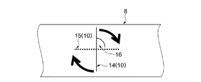
ここで、P1及びQ1は真空引きにより随時変化し、P2は真空排気装置5の能力によって決まる固定値であり、R1は排気配管8によって決まる固定値である。
(1)本実施形態によれば、新排気シーケンスのように上昇工程20、水平工程21、下降工程22を設けることにより、真空引き時の、排気ガス流量及び駆動音及び駆動電流値の最大値を抑えながら、より短時間に真空チャンバー4の圧力を希望の圧力まで減圧することが可能となる。
次に、チャンバー内の気体を排気する特徴的な排気方法の例について、図6及び図7に従って説明する。本実施形態が実施形態1と異なるところは、圧力制御板部10を時間の推移に応じて制御する点にある。尚、実施形態1と同じ点については説明を省略する。
(1)本実施形態によれば、電流値、駆動音が低い値から上げるシーケンス条件にて上昇工程20の排気を行っている。そして、水平工程21、下降工程22を設けることにより、真空引き時の、排気ガス流量及び駆動音及び駆動電流値の最大値を抑えながら、より短時間に真空チャンバー4の圧力を希望の圧力まで減圧することが可能となる。
Claims (1)
- 真空排気装置を用いてチャンバー内の気体を排気する真空排気方法であって、
排気ガス流量、駆動音、および駆動電流のうち少なくとも一つの判定値を設定する工程と、
前記排気ガス流量、前記駆動音、および前記駆動電流のうち少なくとも一つの測定値が前記判定値に到達するまで、前記真空排気装置と前記チャンバーとを接続する配管に設けられた圧力制御板部の動作角を開けていく上昇工程と、
前記少なくとも一つの測定値を維持するように前記動作角の角度調整を行う定常工程と、
を有することを特徴とする真空排気方法。
Priority Applications (1)
| Application Number | Priority Date | Filing Date | Title |
|---|---|---|---|
| JP2011025942A JP5906568B2 (ja) | 2011-02-09 | 2011-02-09 | 真空排気方法 |
Applications Claiming Priority (1)
| Application Number | Priority Date | Filing Date | Title |
|---|---|---|---|
| JP2011025942A JP5906568B2 (ja) | 2011-02-09 | 2011-02-09 | 真空排気方法 |
Publications (3)
| Publication Number | Publication Date |
|---|---|
| JP2012163079A JP2012163079A (ja) | 2012-08-30 |
| JP2012163079A5 JP2012163079A5 (ja) | 2014-03-06 |
| JP5906568B2 true JP5906568B2 (ja) | 2016-04-20 |
Family
ID=46842684
Family Applications (1)
| Application Number | Title | Priority Date | Filing Date |
|---|---|---|---|
| JP2011025942A Expired - Fee Related JP5906568B2 (ja) | 2011-02-09 | 2011-02-09 | 真空排気方法 |
Country Status (1)
| Country | Link |
|---|---|
| JP (1) | JP5906568B2 (ja) |
Families Citing this family (1)
| Publication number | Priority date | Publication date | Assignee | Title |
|---|---|---|---|---|
| JP6318847B2 (ja) * | 2014-05-23 | 2018-05-09 | トヨタ自動車株式会社 | 負圧検出システム |
Family Cites Families (4)
| Publication number | Priority date | Publication date | Assignee | Title |
|---|---|---|---|---|
| JPS6336674U (ja) * | 1986-08-27 | 1988-03-09 | ||
| JPH0321579U (ja) * | 1989-07-10 | 1991-03-04 | ||
| JP2002174173A (ja) * | 2000-12-06 | 2002-06-21 | Denso Corp | ポンプ |
| JP5631539B2 (ja) * | 2008-10-10 | 2014-11-26 | ナブテスコオートモーティブ株式会社 | 真空ポンプ |
-
2011
- 2011-02-09 JP JP2011025942A patent/JP5906568B2/ja not_active Expired - Fee Related
Also Published As
| Publication number | Publication date |
|---|---|
| JP2012163079A (ja) | 2012-08-30 |
Similar Documents
| Publication | Publication Date | Title |
|---|---|---|
| JP4737770B2 (ja) | 真空ポンプの運転制御装置および方法 | |
| JP5437246B2 (ja) | 圧縮機制御の改良 | |
| EP2536953B1 (en) | Apparatus and method for tuning pump speed | |
| WO2010010688A1 (ja) | 処理装置の作動監視システム | |
| JP5114059B2 (ja) | 排気システム | |
| NO338304B1 (no) | Fremgangsmåte for drift av en effektomformermatet kompressor | |
| JP2014074380A (ja) | ドライ真空ポンプ装置 | |
| JP5988224B2 (ja) | モータ制御装置及びモータ制御方法 | |
| JP5906568B2 (ja) | 真空排気方法 | |
| JP4553262B2 (ja) | 真空容積式ポンプの駆動モータを制御するための方法 | |
| JPH05231381A (ja) | ドライ真空ポンプの真空排気容量制御方法とその装置並びにドライ真空ポンプおよび半導体製造用真空処理装置 | |
| JPH09221381A (ja) | 単結晶引上装置の真空排気装置 | |
| JP6992335B2 (ja) | 真空ポンプ起動制御装置 | |
| JP2001012379A (ja) | メンテナンス判定機能付き真空ポンプ | |
| JP4043184B2 (ja) | 圧縮機の制御方法 | |
| JPH03107599A (ja) | 軸流ポンプ装置の制御システム | |
| JPH0712090A (ja) | 圧縮機のサージング発生防止方法 | |
| JP5985182B2 (ja) | 真空ポンプの通気方法および真空ポンプを備えた装置 | |
| US20130045076A1 (en) | Compressor control method and system | |
| JP2002061594A (ja) | 圧縮機の最適負荷制御システム | |
| JPH06288390A (ja) | ターボ送風機あるいは圧縮機配管系の運転制御方法 | |
| JP2002147365A (ja) | 真空排気系の排気圧制御装置 | |
| WO2017159279A1 (ja) | 圧縮機 | |
| JP3590033B2 (ja) | 流体機械のサージ防止方法 | |
| JP5934239B2 (ja) | 真空ボックスに高真空を維持する方法およびシステム |
Legal Events
| Date | Code | Title | Description |
|---|---|---|---|
| A521 | Request for written amendment filed |
Free format text: JAPANESE INTERMEDIATE CODE: A523 Effective date: 20140120 |
|
| A621 | Written request for application examination |
Free format text: JAPANESE INTERMEDIATE CODE: A621 Effective date: 20140120 |
|
| A977 | Report on retrieval |
Free format text: JAPANESE INTERMEDIATE CODE: A971007 Effective date: 20141106 |
|
| A131 | Notification of reasons for refusal |
Free format text: JAPANESE INTERMEDIATE CODE: A131 Effective date: 20141111 |
|
| RD04 | Notification of resignation of power of attorney |
Free format text: JAPANESE INTERMEDIATE CODE: A7424 Effective date: 20150106 |
|
| A521 | Request for written amendment filed |
Free format text: JAPANESE INTERMEDIATE CODE: A523 Effective date: 20150108 |
|
| A131 | Notification of reasons for refusal |
Free format text: JAPANESE INTERMEDIATE CODE: A131 Effective date: 20150707 |
|
| A521 | Request for written amendment filed |
Free format text: JAPANESE INTERMEDIATE CODE: A523 Effective date: 20150806 |
|
| TRDD | Decision of grant or rejection written | ||
| A01 | Written decision to grant a patent or to grant a registration (utility model) |
Free format text: JAPANESE INTERMEDIATE CODE: A01 Effective date: 20160223 |
|
| A61 | First payment of annual fees (during grant procedure) |
Free format text: JAPANESE INTERMEDIATE CODE: A61 Effective date: 20160307 |
|
| R150 | Certificate of patent or registration of utility model |
Ref document number: 5906568 Country of ref document: JP Free format text: JAPANESE INTERMEDIATE CODE: R150 |
|
| LAPS | Cancellation because of no payment of annual fees |