JP5862425B2 - Image forming apparatus - Google Patents
Image forming apparatus Download PDFInfo
- Publication number
- JP5862425B2 JP5862425B2 JP2012083429A JP2012083429A JP5862425B2 JP 5862425 B2 JP5862425 B2 JP 5862425B2 JP 2012083429 A JP2012083429 A JP 2012083429A JP 2012083429 A JP2012083429 A JP 2012083429A JP 5862425 B2 JP5862425 B2 JP 5862425B2
- Authority
- JP
- Japan
- Prior art keywords
- image forming
- image
- photoconductor
- photosensitive member
- forming apparatus
- Prior art date
- Legal status (The legal status is an assumption and is not a legal conclusion. Google has not performed a legal analysis and makes no representation as to the accuracy of the status listed.)
- Active
Links
- 238000004140 cleaning Methods 0.000 claims description 122
- 108091008695 photoreceptors Proteins 0.000 claims description 31
- 230000015572 biosynthetic process Effects 0.000 claims description 5
- 230000007613 environmental effect Effects 0.000 claims description 4
- 238000005755 formation reaction Methods 0.000 claims 3
- 238000010586 diagram Methods 0.000 description 9
- 230000002159 abnormal effect Effects 0.000 description 8
- 238000000034 method Methods 0.000 description 5
- 230000007547 defect Effects 0.000 description 4
- 230000008569 process Effects 0.000 description 4
- 230000009467 reduction Effects 0.000 description 4
- 230000001629 suppression Effects 0.000 description 4
- 230000007423 decrease Effects 0.000 description 3
- 238000003825 pressing Methods 0.000 description 3
- 230000007261 regionalization Effects 0.000 description 3
- 241000519995 Stachys sylvatica Species 0.000 description 2
- 238000010521 absorption reaction Methods 0.000 description 2
- 238000010438 heat treatment Methods 0.000 description 2
- 239000000463 material Substances 0.000 description 2
- 239000002245 particle Substances 0.000 description 2
- 238000003860 storage Methods 0.000 description 2
- XLYOFNOQVPJJNP-UHFFFAOYSA-N water Substances O XLYOFNOQVPJJNP-UHFFFAOYSA-N 0.000 description 2
- 230000002087 whitening effect Effects 0.000 description 2
- 229920006311 Urethane elastomer Polymers 0.000 description 1
- 230000004308 accommodation Effects 0.000 description 1
- 230000009471 action Effects 0.000 description 1
- 230000002547 anomalous effect Effects 0.000 description 1
- 230000008859 change Effects 0.000 description 1
- 239000012141 concentrate Substances 0.000 description 1
- 230000018109 developmental process Effects 0.000 description 1
- 229920001971 elastomer Polymers 0.000 description 1
- 229910052736 halogen Inorganic materials 0.000 description 1
- 150000002367 halogens Chemical class 0.000 description 1
- JEIPFZHSYJVQDO-UHFFFAOYSA-N iron(III) oxide Inorganic materials O=[Fe]O[Fe]=O JEIPFZHSYJVQDO-UHFFFAOYSA-N 0.000 description 1
- 230000007246 mechanism Effects 0.000 description 1
- 238000002360 preparation method Methods 0.000 description 1
- 239000002699 waste material Substances 0.000 description 1
Images


Landscapes
- Control Or Security For Electrophotography (AREA)
- Discharging, Photosensitive Material Shape In Electrophotography (AREA)
- Cleaning In Electrography (AREA)
Description
本発明は、記録紙等の記録シートにトナー像を形成できる複写機、プリンター、ファクシミリ機又はこれらのうち2以上を組み合わせた複合機等の電子写真方式の画像形成装置に関係している。 The present invention relates to an electrophotographic image forming apparatus such as a copying machine, a printer, a facsimile machine, or a combination machine combining two or more of these that can form a toner image on a recording sheet such as recording paper.
記録シートにトナー像を形成できる複写機、プリンター、ファクシミリ機又はこれらのうち2以上を組み合わせた複合機等の画像形成装置は、静電潜像形成プロセスで感光体上に静電潜像を形成し、現像プロセスにて静電潜像を現像して可視トナー像を形成し、転写プロセスにて可視トナー像を記録シートに転写し、或いは一旦中間転写ベルト等の中間転写体に1次転写し中間転写体から記録シートに2次転写し、定着プロセスにてこのように記録シートに転写されたトナー像を記録シートに定着させることができるものが一般的である。 Image forming devices such as copiers, printers, facsimile machines or combinations of two or more of these that can form a toner image on a recording sheet form an electrostatic latent image on a photoreceptor in the electrostatic latent image forming process. Then, the electrostatic latent image is developed by a development process to form a visible toner image, and the visible toner image is transferred to a recording sheet by a transfer process, or is temporarily transferred to an intermediate transfer member such as an intermediate transfer belt. In general, the toner image can be secondarily transferred from the intermediate transfer member to the recording sheet, and the toner image thus transferred onto the recording sheet in the fixing process can be fixed on the recording sheet.
感光体上に形成されるトナー像が記録シートに転写されたあと、感光体上に残留する転写残トナーを含む残留物は感光体のクリーニング装置でクリーニングされるのが一般的である。 After the toner image formed on the photoconductor is transferred to the recording sheet, the residue including the transfer residual toner remaining on the photoconductor is generally cleaned by a photoconductor cleaning device.
感光体のクリーニング装置は種々のタイプのものが知られているが、その中に、感光体上の残留トナー等を該感光体に先端部がカウンター方式で接触するゴムブレードの様な弾性クリーニングブレードでクリーニングするクリーニング装置があり、広く採用されている。 Various types of photosensitive member cleaning devices are known. Among them, an elastic cleaning blade such as a rubber blade whose tip contacts with the residual toner on the photosensitive member in a counter manner. There is a cleaning device that performs cleaning with, and is widely used.
例えば、特開昭60−49381号公報や特開2002−258713号公報には、複写機等の画像形成装置における感光体のクリーニング装置であって、感光体上の残留トナーを該感光体に先端部がカウンター方式で接触する弾性クリーニングブレードでクリーニングするクリーニング装置が記載されている。 For example, Japanese Patent Application Laid-Open Nos. 60-49381 and 2002-258713 disclose a cleaning device for a photosensitive member in an image forming apparatus such as a copying machine, in which residual toner on the photosensitive member is transferred to the leading end of the photosensitive member. A cleaning device is described that cleans with an elastic cleaning blade that contacts in a counter manner.
ここで、「感光体に先端部がカウンター方式で接触するクリーニングブレード」とは、感光体表面に、感光体表面移動方向に逆らう方向から先端部が接触するクリーニングブレードである。参考までに言えば、感光体を逆転させれば、クリーニングブレードは感光体に順方向で先端部が接触するクリーニングブレードとなる。 Here, the “cleaning blade whose tip is in contact with the photoconductor in a counter manner” is a cleaning blade whose tip is in contact with the surface of the photoconductor from the direction opposite to the direction of movement of the photoconductor surface. For reference, if the photosensitive member is reversed, the cleaning blade becomes a cleaning blade whose tip is in contact with the photosensitive member in the forward direction.
感光体上の残留トナー等を該像担持体に先端部がカウンター方式で接触する弾性クリーニングブレードでクリーニングするクリーニング装置については、これまで、クリーニングブレード先端部へのトナーの付着によるクリーニング不良の発生、それに起因する画像不良の発生の問題が指摘されてきた。 For the cleaning device that cleans residual toner on the photoconductor with an elastic cleaning blade whose tip contacts the image carrier in a counter manner, the occurrence of poor cleaning due to the adhesion of toner to the tip of the cleaning blade, The problem of the occurrence of image defects due to this has been pointed out.
また、画像形成動作時の感光体回転速度においては発生しない異音(所謂鳴き)が画像形成動作終了後の感光体の停止直前等の低速回転時に発生することがある点も指摘されてきた。 It has also been pointed out that abnormal noise (so-called squeal) that does not occur at the rotation speed of the photoconductor during the image forming operation may occur during low-speed rotation such as immediately before the photoconductor stops after the completion of the image forming operation.
前記異音は感光体とクリーニングブレード先端の接触による共振音によるものである。このような異音は古くにはあまり耳障りとは思われなかったのであるが、画像形成装置の静音化が進んだ今日では、耳障りと思われることがある。 The abnormal noise is due to a resonance sound caused by contact between the photosensitive member and the tip of the cleaning blade. In the old days, such anomalous noise did not seem to be so harsh, but today, when the image forming apparatus has been quieter, it may seem harsh.
このような問題に対して、特開昭60−49381号公報には、クリーニングブレードに付着したトナーを除去するためにクリーニング終了後に感光体を僅かに逆回転させるとともに、感光体逆転時には感光体逆転によるクリーニングブレードの損傷を抑制するためにクリーニングブレードを感光体から離隔させることが記載されている。 In order to solve this problem, Japanese Patent Application Laid-Open No. 60-49381 discloses that the photosensitive member is rotated slightly backward after the cleaning to remove the toner adhering to the cleaning blade. In order to suppress the damage of the cleaning blade due to the above, it is described that the cleaning blade is separated from the photoreceptor.
特開2002−258713号公報には、画像形成動作終了後の感光体の停止直前の低速回転時に発生することがある感光体とクリーニングブレード先端の接触による共振音(所謂鳴き)を抑制するために、共振音が発生する低速回転に達する前に感光体を逆回転制御することが記載されている。また、感光体の逆回転によりクリーニングブレードに付着したトナーを除去することも記載されている。 Japanese Patent Laid-Open No. 2002-258713 discloses a method for suppressing resonance noise (so-called noise) caused by contact between the photosensitive member and the tip of the cleaning blade, which may occur during low-speed rotation immediately before the photosensitive member stops after completion of the image forming operation. Further, it is described that the photosensitive member is reversely rotated before the low-speed rotation at which the resonance sound is generated. It also describes that the toner adhering to the cleaning blade is removed by the reverse rotation of the photosensitive member.
しかしながら、回転駆動される感光体表面を帯電装置で帯電させ、前記感光体表面の前記帯電装置による帯電域に静電潜像形成装置で静電潜像を形成し、前記静電潜像を現像装置で現像して可視トナー像を形成する画像形成部を少なくとも一つ含み、前記画像形成部で形成されるトナー像を記録シートに転写、定着させることができ、前記画像形成部の感光体上の転写残トナーを含む残留物をクリーニング装置でクリーニングする画像形成装置であって、前記クリーニング装置として、前記感光体にカウンター方式で弾性先端部が当接されるクリーニングブレードを有するクリーニング装置を採用する画像形成装置では、次の問題もある。 However, the surface of the photoconductor to be rotationally driven is charged by a charging device, an electrostatic latent image is formed by an electrostatic latent image forming device in a charging area of the surface of the photoconductor by the charging device, and the electrostatic latent image is developed. The image forming unit includes at least one image forming unit that forms a visible toner image by developing with the apparatus, and the toner image formed in the image forming unit can be transferred and fixed on a recording sheet. An image forming apparatus that cleans residuals including transfer residual toner with a cleaning device, wherein the cleaning device includes a cleaning blade having a resilient tip abutted against the photoconductor in a counter manner. The image forming apparatus also has the following problem.
上記タイプの画像形成装置では、前記帯電装置による放電生成物の感光体への局所的集中付着を抑制しなければ、記録シート搬送方向を横切る方向(以下、「CD方向」と言うことがある。)に画像の白ぬけが発生することがある、という問題である。 In the above-mentioned type of image forming apparatus, unless the local concentration and adhesion of the discharge product to the photoconductor by the charging device is suppressed, it may be referred to as a direction crossing the recording sheet conveyance direction (hereinafter referred to as “CD direction”). ), Whitening of the image may occur.
この画像白ぬけは所謂像流れに起因する。像流れとは、帯電装置からの放電生成物が感光体表面へ付着し、付着した放電生成物の吸水作用で感光体表面が低抵抗化し、次に静電潜像を形成するとき潜像が流れる現象で、特に、高湿環境放置における帯電装置直下の感光体面部にて発生が顕著になり、画像としては、中間調画像のハーフトーンで、CD方向の白抜け画像として発生する。 This image whitening is caused by so-called image flow. Image flow means that the discharge product from the charging device adheres to the surface of the photoconductor, the surface of the photoconductor becomes low resistance due to the water absorption action of the attached discharge product, and then the latent image is formed when an electrostatic latent image is formed. This phenomenon is particularly noticeable on the surface of the photosensitive member directly under the charging device when left in a high-humidity environment, and the image is a halftone of a halftone image and is generated as a blank image in the CD direction.
このような白ぬけ画像は、実際には、十数枚程度の画像形成動作で回復し、発生しなくなる。画像形成動作終了後に感光体が停止していると帯電装置直下の感光体面部に放電生成物が集中して付着してしまうが、十数枚程度の画像形成動作で回復する。 Such a whitened image is actually recovered by an image forming operation of about a dozen sheets and is not generated. If the photoconductor is stopped after the image forming operation is completed, the discharge products concentrate and adhere to the surface of the photoconductor immediately below the charging device, but are recovered by an image forming operation of about a dozen sheets.
本発明者の研究によると、前記画像形成部でトナー像が形成され、該トナー像が記録シートに転写される画像形成動作の終了後の非画像形成動作時に、感光体を少しずつ回転させることで、換言すれば、感光体を微小角度で回す、発明者等において「ちょろ回し」と称する感光体微小角度回転を行なうことで、感光体上に放電生成物を散らして、像流れ現象、延いては画像の白抜け現象の発生を抑制できる。 According to the inventor's research, a toner image is formed in the image forming unit, and the photoreceptor is rotated little by little during a non-image forming operation after the image forming operation is completed. In other words, by rotating the photosensitive member at a small angle, or by rotating the photosensitive member at a small angle, which is called “swift rotation” by the inventors, the discharge products are scattered on the photosensitive member, thereby causing an image flow phenomenon and a delay. Therefore, the occurrence of white spots in the image can be suppressed.
しかし、画像形成動作の終了後に感光体を微小角度で回すと、前記異音が発生し易く、その異音は画像形成動作の終了後に発生するものであるから、耳障りである。特に、像流れの発生しやすい高湿環境では感光体とクリーニングブレードの摩擦が大きくなるため、鳴きが発生しやすい。 However, if the photoconductor is rotated at a small angle after the image forming operation is completed, the abnormal noise is likely to be generated, and the abnormal noise is generated after the image forming operation is completed. In particular, in a high-humidity environment where image flow is likely to occur, the friction between the photosensitive member and the cleaning blade increases, so that noise is likely to occur.
さらに、感光体微小角度回転時には、感光体とクリーニングブレードの摩擦が大きい状態で感光体を空回転させるので、感光体とクリーニングブレードヘの負荷が大きく、それらの摩耗が促進されてしまう。 Further, when the photoconductor is rotated at a minute angle, the photoconductor is idly rotated in a state where the friction between the photoconductor and the cleaning blade is large, so that the load on the photoconductor and the cleaning blade is large and wear of the photoconductor is promoted.
前記特許文献1、2はクリーニングブレードへのトナー付着の抑制について、また、特許文献2は感光体停止直前の鳴きの抑制について記載があるが、いずれの文献にも、帯電装置からの放電生成物に起因する像流れ現象の抑制、その抑制のために前記「ちょろ回し」を採用する場合の鳴き発生の抑制や感光体とクリーニングブレードの摩擦の低減の必要性に関して何ら触れるところがない。
本発明は、回転駆動される感光体表面を帯電装置で帯電させ、前記感光体表面の前記帯電装置による帯電域に、形成しようとする画像に応じた画像露光を施して静電潜像を形成し、前記静電潜像を現像装置で現像して可視トナー像を形成する画像形成部を少なくとも一つ含み、前記画像形成部で形成されるトナー像を記録シートに転写、定着させることができ、前記画像形成部の感光体上の転写残トナーを含む残留物をクリーニング装置でクリーニングする画像形成装置であって、前記クリーニング装置として、前記感光体にカウンター方式で弾性先端部が当接されるクリーニングブレードを有するクリーニング装置を採用する画像形成装置であり、
前記感光体と前記クリーニング装置のクリーニングブレードの摩擦力を軽減して像流れ現象抑制のための感光体回転を行なうことができ、また、該摩擦力軽減により像流れ現象抑制のための感光体回転時の「異音」発生を抑制するとともに感光体とクリーニングブレードの長寿命化を図ることができる画像形成装置を提供することを課題とする。
In the present invention, the surface of a photoconductor to be rotated is charged by a charging device, and an electrostatic latent image is formed by performing image exposure according to an image to be formed on a charging area of the surface of the photoconductor by the charging device. And at least one image forming unit that develops the electrostatic latent image with a developing device to form a visible toner image, and the toner image formed by the image forming unit can be transferred and fixed on a recording sheet. An image forming apparatus for cleaning a residue including transfer residual toner on the photosensitive member of the image forming unit with a cleaning device, wherein the elastic tip is brought into contact with the photosensitive member in a counter manner as the cleaning device. An image forming apparatus employing a cleaning device having a cleaning blade,
It is possible to reduce the frictional force between the photosensitive member and the cleaning blade of the cleaning device to perform rotation of the photosensitive member to suppress the image flow phenomenon, and to reduce the frictional force, to rotate the photosensitive member to suppress the image flow phenomenon. It is an object of the present invention to provide an image forming apparatus capable of suppressing the occurrence of “abnormal noise” at the time and extending the lifetime of the photosensitive member and the cleaning blade.
本発明は前記課題を解決するため、
回転駆動される感光体表面を帯電装置で帯電させ、前記感光体表面の前記帯電装置による帯電域に、形成しようとする画像に応じた画像露光を施して静電潜像を形成し、前記静電潜像を現像装置で現像して可視トナー像を形成する画像形成部を少なくとも一つ含み、前記画像形成部で形成されるトナー像を記録シートに転写、定着させることができ、前記画像形成部の感光体上の転写残トナーを含む残留物をクリーニング装置でクリーニングする画像形成装置であって、前記クリーニング装置として、前記感光体にカウンター方式で弾性先端部が当接されるクリーニングブレードを有するクリーニング装置を採用する画像形成装置であり、
前記感光体を画像形成のための正転方向にも、該正転方向に対する逆転方向にも回転駆動可能な感光体駆動部と、
前記感光体駆動部の制御部を含んでおり、
前記制御部は、前記画像形成部でトナー像が形成され、該トナー像が記録シートに転写される画像形成動作の終了後の非画像形成動作時に、前記感光体駆動部に前記感光体を、前記帯電装置による放電生成物の前記感光体への局所的集中付着を抑制するように、前記帯電装置による帯電幅の移動距離が確保できる微小角度で逆転させることができる画像形成装置を提供する。
In order to solve the above problems, the present invention
The surface of the photoconductor to be rotated is charged by a charging device, and an electrostatic latent image is formed on the surface of the photoconductor surface charged by the charging device according to the image to be formed to form an electrostatic latent image. The image forming unit includes at least one image forming unit that develops an electrostatic latent image by a developing device to form a visible toner image, and the toner image formed by the image forming unit can be transferred and fixed on a recording sheet. An image forming apparatus that cleans residuals including transfer residual toner on a photosensitive member of a part with a cleaning device, the cleaning device having a cleaning blade with which an elastic tip is brought into contact with the photosensitive member in a counter manner An image forming apparatus that employs a cleaning device,
A photoconductor drive unit capable of rotationally driving the photoconductor in a normal rotation direction for image formation and in a reverse direction with respect to the normal rotation direction;
Including a control unit of the photosensitive member driving unit,
In the non-image forming operation after completion of the image forming operation in which a toner image is formed in the image forming unit and the toner image is transferred to a recording sheet, the control unit is configured to put the photoconductor in the photoconductor driving unit. Provided is an image forming apparatus capable of reversing at a small angle that can secure a moving distance of a charging width by the charging device so as to suppress a local concentrated adhesion of a discharge product by the charging device to the photoreceptor.
本発明に係る画像形成装置によると、前記画像形成部の回転駆動される感光体表面を帯電装置で帯電させ、前記感光体表面の帯電装置による帯電域に、形成しようとする画像に応じた画像露光を施して静電潜像を形成し、前記静電潜像を現像装置で現像して可視トナー像を形成し、前記トナー像を記録シートに転写し、定着させることができ、前記感光体上の転写残トナーを含む残留物をクリーニング装置でクリーニングすることができる。 According to the image forming apparatus of the present invention, the surface of the photosensitive member that is rotationally driven by the image forming unit is charged by the charging device, and the image corresponding to the image to be formed is formed in the charging region of the charging surface of the photosensitive member surface. An electrostatic latent image is formed by exposure, the electrostatic latent image is developed by a developing device to form a visible toner image, and the toner image can be transferred to a recording sheet and fixed, and the photoconductor The residue including the upper transfer residual toner can be cleaned with a cleaning device.
本発明に係る画像形成装置によると、前記感光体駆動部の制御部は、前記画像形成動作終了後の非画像形成動作時に、前記感光体駆動部に前記感光体を、前記帯電装置による放電生成物の前記感光体への局所的集中付着を抑制するように、前記帯電装置による帯電幅の移動距離が確保できる微小角度で逆転させることができる。 According to the image forming apparatus of the present invention, the control unit of the photoconductor driving unit generates the photoconductor on the photoconductor driving unit during the non-image forming operation after the completion of the image forming operation, and generates a discharge by the charging device. In order to suppress local concentration and adhesion of the object to the photoconductor, the object can be reversed at a minute angle that can secure a moving distance of the charging width by the charging device .
このような感光体の逆転により、クリーニングブレードを感光体に対し順方向に接触する状態とし、それにより感光体とクリーニングブレードの相互摩擦を軽減しつつ像流れ現象抑制のための感光体回転を行なうことができ、また、該摩擦力軽減により像流れ現象抑制のための感光体回転時の「異音」発生を抑制するとともに感光体とクリーニングブレードの摩耗を抑制してそれらの長寿命化を図ることができる。 By such reversal of the photoconductor, the cleaning blade is brought into contact with the photoconductor in the forward direction, thereby rotating the photoconductor to suppress the image flow phenomenon while reducing the mutual friction between the photoconductor and the cleaning blade. In addition, by reducing the frictional force, the generation of “abnormal noise” at the time of rotating the photoconductor for suppressing the image flow phenomenon is suppressed, and the wear of the photoconductor and the cleaning blade is suppressed, thereby extending their life. be able to.
画像形成動作時の画像形成枚数が多くなってくると(従って、帯電装置の動作時間が長くなってくると)、それだけ帯電装置による放電生成物の量が増し、画像形成動作終了後に帯電装置から感光体へ付着してくる放電生成物量が増す。
画像形成動作時の画像形成枚数が予め定めた枚数より少なく、感光体への放電生成物付着を無視してもよい場合もあり、そのような場合、前記制御部は感光体を逆転させなくてもよい。
As the number of images formed during the image forming operation increases (and accordingly, the operation time of the charging device becomes longer), the amount of discharge products by the charging device increases accordingly. The amount of discharge products adhering to the photoreceptor increases.
In some cases, the number of images formed during the image forming operation is less than a predetermined number and the discharge product adhesion to the photoconductor may be ignored. In such a case, the control unit does not have to reverse the photoconductor. Also good.
上述のとおり、画像形成動作時の画像形成枚数が多くなってくると(従って、帯電装置の動作時間が長くなってくると)、それだけ帯電装置による放電生成物の量が増し、画像形成動作終了後に帯電装置から感光体へ付着してくる放電生成物量が増す。そこで、前記制御部として、前記画像形成部でトナー像が形成され、該トナー像が記録シートに転写される画像形成動作の終了後の非画像形成動作時に、前記感光体駆動部に前記感光体を逆転させるにあたり、前記画像形成動作時の画像形成枚数に応じた回数、前記微小角度で逆転させる制御部を採用してもよい。この場合も、前記感光体逆転「回数」には「0」回も含まれる。 As described above, as the number of images formed during the image forming operation increases (and accordingly the operation time of the charging device becomes longer), the amount of discharge products by the charging device increases accordingly, and the image forming operation ends. The amount of discharge products that later adhere to the photoreceptor from the charging device increases. Therefore, as the control unit, a toner image is formed in the image forming unit, and the toner image is transferred to the recording sheet. When reversing the image, a control unit that reverses the image at the minute angle a number of times corresponding to the number of images formed during the image forming operation may be employed. Again, said the photoreceptor reverse "count" Ru also contains "0" times.
前記制御部は、感光体の逆転開始、特に最初の逆転開始によるクリーニングブレードの損傷を抑制するため、前記感光体駆動部に前記感光体を複数回逆転させるとき、1回目逆転時の感光体逆転速度を2回目以後の逆転時の感光体逆転速度より遅く設定してもよい。1回目逆転中に感光体逆転速度を変化させるような場合は、例えば、1回目逆転時の平均逆転速度を2回目以後の逆転時の逆転速度より遅く設定すればよい。 In order to suppress the cleaning blade damage due to the start of the reverse rotation of the photosensitive member, particularly the first reverse rotation, the control unit reverses the photosensitive member at the first reverse rotation when the photosensitive member drive unit rotates the photosensitive member a plurality of times. The speed may be set slower than the photosensitive member reverse rotation speed at the second and subsequent reverse rotations. When the photosensitive member reverse rotation speed is changed during the first reverse rotation, for example, the average reverse rotation speed during the first reverse rotation may be set slower than the reverse rotation speed during the second and subsequent reverse rotations.
本発明に係る画像形成装置は、前記画像形成部が一つ設けられているだけのものでもよいが(この場合はモノクロ画像形成装置)、前記画像形成部が複数設けられており、前記画像形成部で形成されるトナー像が中間転写体に一次転写され、前記中間転写体から前記記録シートに二次転写される画像形成装置でもよい。この場合には、前記制御部は、前記感光体駆動部に前記感光体を逆転させるとき、前記各画像形成部の感光体の逆転タイミングを画像形成部ごとにずらせばよい。 The image forming apparatus according to the present invention may have only one image forming unit (in this case, a monochrome image forming apparatus), but a plurality of the image forming units are provided, and the image forming unit An image forming apparatus may be used in which a toner image formed in a portion is primarily transferred to an intermediate transfer member and secondarily transferred from the intermediate transfer member to the recording sheet. In this case, the control unit may shift the reversal timing of the photoconductor of each image forming unit for each image forming unit when the photoconductor driving unit reverses the photoconductor.
画像形成動作時の画像形成枚数が多くなってくると(従って、帯電装置の動作時間が長くなってくると)、それだけ帯電装置による放電生成物の量が増す一方、前記帯電装置から感光体への放電生成物付着は画像形成動作終了からの時間の経過ととともに減少する。そこで、前記制御部は、前記感光体駆動部に前記感光体を少なくとも1回逆転させるとき、前記画像形成動作終了から各回の感光体逆転開始までの時間を前記画像形成動作時の画像形成枚数に応じて制御してもよい。 As the number of images formed during the image forming operation increases (and accordingly, the operation time of the charging device becomes longer), the amount of discharge products by the charging device increases accordingly, while the charging device transfers to the photoreceptor. This discharge product adhesion decreases with the passage of time from the end of the image forming operation. Therefore, when the control unit causes the photoconductor driving unit to reverse the photoconductor at least once, the time from the end of the image forming operation to the start of each photoconductor reverse rotation is the number of images formed during the image forming operation. You may control according to it.
また、画像形成装置環境の絶対湿度が高いほど放電生成物による感光体上の像流れ現象が生じやすいので、前記制御部は、前記感光体駆動部に前記感光体を少なくとも1回逆転させるとき、前記画像形成動作終了から各回の感光体逆転開始までの時間を前記画像形成動作時の画像形成枚数及び画像形成装置環境湿度のうち少なくとも一方に応じて制御してもよい。 In addition, the higher the absolute humidity of the image forming apparatus environment, the more likely the image flow phenomenon on the photosensitive member due to the discharge product occurs, so that the control unit reverses the photosensitive member to the photosensitive member driving unit at least once. The time from the end of the image forming operation to the start of the reversal of the photosensitive member each time may be controlled according to at least one of the number of images formed during the image forming operation and the environmental humidity of the image forming apparatus.
前記クリーニング装置のクリーニングブレードは、前記感光体の正転時と逆転時で前記感光体への当接部分の該感光体との摩擦係数が異なっていてもよい。その場合、感光体逆転時の感光体とクリーニングブレードの相互摩擦を軽減するために、前記感光体逆転時に前記感光体へ当接する部分の摩擦係数の方を前記感光体正転時に前記感光体へ当接する部分の摩擦係数より小さくすればよい。 The cleaning blade of the cleaning device may have a different coefficient of friction with the photoconductor at the contact portion with the photoconductor when the photoconductor is rotated forward and reverse. In that case, in order to reduce the mutual friction between the photoconductor and the cleaning blade when the photoconductor is reversed, the friction coefficient of the portion that contacts the photoconductor when the photoconductor is reversed is transferred to the photoconductor when the photoconductor is rotated forward. What is necessary is just to make it smaller than the friction coefficient of the part which contact | abuts.
前記制御部が、前記画像形成部でトナー像が形成され、該トナー像が記録シートに転写される画像形成動作の終了後の非画像形成動作時に、前記感光体駆動部に前記感光体を、前記画像形成動作時の画像形成枚数に応じた回数、前記微小角度で逆転させるときの、該画像形成動作時の画像形成枚数に応じた回数は、前記画像形成動作の終了から前記放電生成物の前記感光体への付着が無くなるとみなすことができる時までの時間範囲内で決められる回数とすることができる。
また、前記帯電装置から感光体への放電生成物付着量は画像形成動作終了からの時間の経過ととともに減少するので、前記制御部は、前記感光体駆動部に前記感光体を複数回逆転させるとき、逆転開始の時間間隔を逆転回数が増えるに応じて長くしてもよい。
In the non-image forming operation after the completion of the image forming operation in which the control unit forms a toner image in the image forming unit and the toner image is transferred to a recording sheet, The number of times corresponding to the number of image forming operations during the image forming operation, and the number of times corresponding to the number of image forming operations during the image forming operation when reversing at the minute angle are the number of discharge products from the end of the image forming operation. The number of times can be determined within a time range until it can be considered that adhesion to the photosensitive member is eliminated.
In addition, since the amount of discharge product adhesion from the charging device to the photoconductor decreases with the passage of time from the end of the image forming operation, the control unit causes the photoconductor drive unit to reverse the photoconductor a plurality of times. In some cases, the time interval for starting reverse rotation may be increased as the number of reverse rotations increases.
以上説明したように本発明によると、回転駆動される感光体表面を帯電装置で帯電させ、前記感光体表面の前記帯電装置による帯電域に、形成しようとする画像に応じた画像露光を施して静電潜像を形成し、前記静電潜像を現像装置で現像して可視トナー像を形成する画像形成部を少なくとも一つ含み、前記画像形成部で形成されるトナー像を記録シートに転写、定着させることができ、前記画像形成部の感光体上の転写残トナーを含む残留物をクリーニング装置でクリーニングする画像形成装置であって、前記クリーニング装置として、前記感光体にカウンター方式で弾性先端部が当接されるクリーニングブレードを有するクリーニング装置を採用する画像形成装置であり、
前記感光体と前記クリーニング装置のクリーニングブレードの摩擦力を軽減して像流れ現象抑制のための感光体回転を行なうことができ、また、該摩擦力軽減により像流れ現象抑制のための感光体回転時の「異音」発生を抑制するとともに感光体とクリーニングブレードの長寿命化を図ることができる画像形成装置を提供することができる。
As described above, according to the present invention, the surface of the photoconductor to be rotationally driven is charged by the charging device, and image exposure corresponding to the image to be formed is performed on the charging area of the surface of the photoconductor by the charging device. It includes at least one image forming unit that forms an electrostatic latent image, develops the electrostatic latent image with a developing device to form a visible toner image, and transfers the toner image formed by the image forming unit to a recording sheet An image forming apparatus capable of fixing and cleaning a residue including a transfer residual toner on the photosensitive member of the image forming unit with a cleaning device, wherein the elastic member has a counter-type elastic tip as the cleaning device. An image forming apparatus that employs a cleaning device having a cleaning blade against which a portion comes into contact,
It is possible to reduce the frictional force between the photosensitive member and the cleaning blade of the cleaning device to perform rotation of the photosensitive member to suppress the image flow phenomenon, and to reduce the frictional force, to rotate the photosensitive member to suppress the image flow phenomenon. It is possible to provide an image forming apparatus capable of suppressing the occurrence of “abnormal noise” at the time and extending the lifespan of the photosensitive member and the cleaning blade.
以下、図面を参照して本発明に係る画像形成装置例等について説明する。
図1は本発明に係る画像形成装置の1例の構成の概略を示している。図1の画像形成装置100は電子写真方式で画像形成するタンデム型のフルカラープリンタである。
Hereinafter, an example of an image forming apparatus according to the present invention will be described with reference to the drawings.
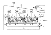
FIG. 1 schematically shows the configuration of an example of an image forming apparatus according to the present invention. The
プリンター100は、駆動ローラー71とこれに対向するローラー72に巻き掛けられた無端の中間転写ベルト7を有している。転写ベルト7は、図示省略のベルト駆動部により駆動される駆動ローラー71により図中反時計方向(図中矢印方向)CCWに回される。
The
ローラー72には転写ベルト7上の2次転写残トナー等を清掃するクリーニング装置73が臨んでおり、駆動ローラー71には2次転写ローラー8が臨んでいる。
A
2次転写ローラー8は図示省略の押圧手段にて駆動ローラー71に支持された中間転写ベルト7の部分に押圧され、中間転写ベルト7との間にニップ部を形成し、中間転写ベルト7の回転に従動して、或いは、後述するように該ニップ部に送り込まれる記録媒体Sの移動に従動して、或いは駆動されて回転することができる。2次転写ローラー8には、図示省略の電源から2次転写バイアスを印加することができる。
The secondary transfer roller 8 is pressed against a portion of the
中間転写ベルト7及び2次転写ローラー8の上方には定着装置9が配置されており、下方にはタイミングローラ対11が配置されており、さらにその下方に、記録紙等の記録シートSを収容した記録シート収容カセット10が配置されている。
A fixing
定着装置9はハロゲンランプヒータ等の熱源を備えた定着加熱ローラーとこれに圧接される加圧ローラーとを含むものである。
The fixing
記録シート収容カセット10に収容された記録シートSは、シート供給装置101にて1枚ずつ引き出してタイミングローラ対11へ供給することができる。
The recording sheets S stored in the recording
中間転写ベルト7を巻き掛けたローラー71、72の間には、転写ベルト7に沿って、ローラー72からローラー71に向けて、イエロー画像形成部Y、マゼンタ画像形成部M、シアン画像形成部C及びブラック画像形成部Kがこの順序で配置されている。
Between the
Y、M、C、Kの各画像形成部は、静電潜像担持体としてドラム型の感光体1を備えており、該感光体の周囲に帯電器2、現像装置4及びクリーニング装置5がこの順序で配置されている。各感光体1に対する露光部を含む露光装置3も設けられている。
Each of the image forming units Y, M, C, and K includes a drum-type
各画像形成部の感光体1にはベルト7を間にして1次転写ローラー6が対向配置されている。1次転写ローラー6は、図示省略の押圧手段にて感光体1の方向へ押圧され、ベルト7に接触して従動回転するとともにベルト7を感光体1に接触させることができる。
A primary transfer roller 6 is disposed opposite to the
1次転写ローラー6には、感光体1上に形成されるトナー像をベルト7へ1次転写するための1次転写バイアスを図示省略の電源から印加できる。
A primary transfer bias for primary transfer of the toner image formed on the
各画像形成部の感光体1は、それとは限定されないが、本例では負帯電性の感光体であり、感光体駆動部DY、DM、DC、DK(図2参照)にて図中時計方向に回転駆動できる。感光体駆動部DY、DM、DC、DKは全部或いは一部が各画像形成部に共通のものであってもよい。
The
各画像形成部の帯電器2は、本例ではスコロトロン帯電器であり、所定のタイミングで図示省略の電源から感光体帯電用の電圧が印加されて感光体表面を静電潜像形成に先だって一様に所定電位に帯電させることができる。。
The
各画像形成部の現像器4は、図示省略の電源から現像バイアスが印加される現像ローラで感光体1上の静電潜像を反転現像できる。
The developing device 4 of each image forming unit can reversely develop the electrostatic latent image on the
画像形成部Yの現像器4にはトナーボトル14Yからイエロートナーを補給することができる。同様に、画像形成部Mの現像器4にはトナーボトル14Mからマゼンタトナーを、画像形成部Cの現像器4にはトナーボトル14Cからシアントナーを、画像形成部Kの現像器4にはトナーボトル14Kからブラックトナーをそれぞれ補給できる。
Yellow toner can be supplied to the developing device 4 of the image forming unit Y from the
各画像形成部のクリーニング装置5については後述する。
The
図2にプリンター100の制御回路の概略をブロック図で示してある。制御回路中の制御部Contはプリンター100の動作を制御するものである。画像形成部Y、M、C及びKのそれぞれ、従って各画像形成部における感光体駆動部DY、DM、DC、DK、帯電器2、画像露光装置3、現像装置4の回転駆動部(図示省略)や現像バイアス印加電源等はこの制御部Contからの指示に基づいて所定のタイミングで動作する。また、記録媒体の搬送機構、定着装置9等のプリンター100の他の各部もこの制御部Contからの指示に基づいて動作する。
FIG. 2 is a block diagram showing an outline of the control circuit of the
制御部Contには操作パネルPAも接続されており(図2参照)、このパネルにおいて画像形成モード、画像形成枚数の設定等を行える。また、制御部Contにはプリンター環境湿度を検出する湿度センサs1からの湿度情報が入力される。 An operation panel PA is also connected to the control unit Cont (see FIG. 2), and an image forming mode, the number of images formed, and the like can be set on this panel. Further, humidity information from the humidity sensor s1 that detects the printer environmental humidity is input to the control unit Cont.
このプリンターによると、Y、M、C、Kの画像形成部のうち1又は2以上を用いて制御部Contの指示のもとに画像を形成することができる。
画像形成部Y、M、C及びKのすべてを用いてフルカラー画像を形成する場合を例にとると、先ず、イエロー画像形成部Yにおいてイエロートナー像を形成し、これを転写ベルト7に1次転写する。
According to this printer, an image can be formed under the instruction of the control unit Cont using one or more of the Y, M, C, and K image forming units.
Taking a case where a full color image is formed using all of the image forming portions Y, M, C, and K as an example, first, a yellow toner image is formed in the yellow image forming portion Y, and this is formed on the
すなわち、イエロー画像形成部Yにおいて、感光体1が図中時計方向に回転駆動され、帯電器2にて表面が一様に所定電位に帯電され、該帯電域に露光装置3からイエロー画像に対応する画像露光が施され、感光体1上にイエロー画像に対応する静電潜像が形成される。この静電潜像はイエロートナーを有する現像装置4の現像バイアスが印加された現像ローラー41にて現像されて可視イエロートナー像となる。該イエロートナー像は1次転写ローラー6にて転写ベルト7上に1次転写される。このとき、1次転写ローラー6には図示省略の電源から1次転写バイアスが印加される。
That is, in the yellow image forming portion Y, the
同様にして、マゼンタ画像形成部Mにおいてマゼンタトナー像が形成されて転写ベルト7に転写され、シアン画像形成部Cにおいてシアントナー像が形成されて転写ベルト7に転写され、ブラック画像形成部Kにおいてブラックトナー像が形成されて転写ベルト7に転写される。
Similarly, a magenta toner image is formed in the magenta image forming unit M and transferred to the
イエロー、マゼンタ、シアン、ブラックのトナー像はこれらが中間転写ベルト7上に重ねて転写されるタイミングで形成される。
かくして転写ベルト7上に形成された多重トナー像は転写ベルト7の回動により2次転写ローラー8へ向け移動する。
Yellow, magenta, cyan, and black toner images are formed at a timing when these toner images are transferred onto the
Thus, the multiple toner image formed on the
一方、記録シートSが記録媒体収容カセット10からシート供給装置101にて引き出され、タイミングローラ対11へ供給され、待機している。
On the other hand, the recording sheet S is pulled out from the recording
タイミングローラ対11のところで待機する記録シートSは、中間転写ベルト7にて送られてくる多重トナー像に合わせて、転写ベルト7と2次転写ローラ8とのニップ部に供給される。該多重トナー像は図示省略の電源から2次転写バイアスが印加された2次転写ローラー8にて記録シートS上に2次転写される。
The recording sheet S waiting at the
その後記録シートSは定着装置9に通され、そこで多重トナー像が加熱加圧下に記録シートSに定着される。記録シートSはひき続き、排出ローラー対12にて排出トレイ13に排出される。
Thereafter, the recording sheet S is passed through the fixing
トナー像のベルト7への1次転写において感光体1上に残留する転写残トナー等はクリーニング装置5で清掃され、2次転写によりベルト7上に残留する2次転写残トナー等はクリーニング装置73で清掃される。これら清掃除去されたトナーはそれぞれ図示省略の搬送手段にて廃棄容器へ送られる。
In the primary transfer of the toner image to the
クリーニング装置5についてさらに説明する。クリーニング装置5は図3に示すように、ウレタンゴム等からなる弾性クリーニングブレード51の先端部511を感光体1に押し当て、感光体1上の転写残トナーtを掻き落とし除去するものである。
The
クリーニングブレード51はカウンター方式で、換言すれば、感光体表面移動方向に逆らう方向から感光体1に押し当てられ、感光体1上の転写残トナーtを掻き落とし除去する。図示例では、クリーニングブレード51は支持部材50に支持されてクリーニング装置ケースに保持されている。
In other words, the
この種のクリーニング装置は構成が簡単であり、且つ、クリーニング性能にも優れているため一般的に用いられている。 This type of cleaning apparatus is generally used because of its simple structure and excellent cleaning performance.
近年は高画質化の観点からトナーの小粒径化が進んできている。小粒径トナーはクリーニングブレード51と感光体1との間をすり抜けやすいため、感光体1とクリーニングブレード51との当接力を高くすることでクリーニング性能を確保している。しかし、当接力が高いほど感光体1とクリーニングブレード51の相互擦れによる、「クリーニングブレードの鳴き」と呼ばれる異音が大きくなる。
In recent years, the particle size of toner has been reduced from the viewpoint of higher image quality. Since the small particle size toner easily slips between the
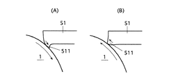
図4は感光体回転時のクリーニングブレード51の鳴きを説明する図である。
図4(A)に示すように、感光体クリーニングにおいては感光体1が図中CW方向に回転している状態において、クリーニングブレード51の先端部511が感光体1との間の摩擦力により感光体回転方向CWに引っ張られる。
FIG. 4 is a diagram for explaining the noise of the
As shown in FIG. 4A, in the photoconductor cleaning, the
そのように引っ張られるにつれてクリーニングブレード51の反発弾性力が大きくなり、反発弾性力がクリーニングブレード51と感光体1との間の摩擦力よりも大きくなると、クリーニングブレード51の先端部511が図4(B)のように感光体回転とは逆方向に動く。この反発動作時のクリーニングブレード51と感光体1とのこすれによって鳴きが発生する。このような鳴きは、感光体回転速度が印字動作時(画像形成動作時)のそれより小さくなる時にブレード先端部511が感光体回転とは逆方向に動きやすくなり、発生し易い。
The pulling elastic force of the
高湿環境下などでは、クリーニングブレード51と感光体1との間の摩擦力が大きくなることでクリーニングブレード先端部511の引っ張られる量がより大きくなる。これにより、反発動作時により大きな力が掛かるため、クリーニングブレード51の鳴きがより大きくなる。このように、摩擦力が大きいとクリーニングブレード51は鳴きやすくなるのである。
In a high-humidity environment or the like, the frictional force between the
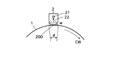
図5は帯電器2と感光体1上に付着する放電生成物の関係を説明する図である。
印字動作終了後、感光体1と帯電器2の間にはコロナ放電により発生した放電生成物が浮遊している。浮遊した放電生成物は吸水作用により帯電器2の周囲に付着する。ここで、帯電電極21やメッシュ状グリッド電極22などに付着した放電生成物は錆の原因となる。さらに、浮遊した放電生成物は帯電器直下の感光体1表面にも付着してしまう。この感光体表面に付着した放電生成物200は像流れと呼ばれる画像不良を引き起こす。
FIG. 5 is a diagram for explaining the relationship between the
After the printing operation is completed, a discharge product generated by corona discharge is floating between the
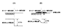
図6は感光体への放電生成物付着により画像不良が発生することを説明する図である。
図6(A)は感光体1表面上の非トナー像形成部とトナー像形成部での電荷の様子と該両部分間の電位差ΔVaを表している。図6(B)は感光体1表面に放電生成物が付着した場合の状態を示している。
FIG. 6 is a diagram for explaining that an image defect occurs due to the discharge product adhering to the photoreceptor.
FIG. 6A shows the state of charge in the non-toner image forming portion and the toner image forming portion on the surface of the
図6(B)に示すように放電生成物が付着することで感光体表面が低抵抗化し、電荷が流れてしまう。これにより、トナー像形成部と非トナー像形成部間の電位差ΔVbが放電生成物の付着がないときの電位差△Vaより小さくなってしまう。よって、放電生成物付着部のみ他の部分に比べ画像濃度が下がってしまい、記録シート搬送方向を横切る幅方向(CD方向)にわたって画像の白抜けが発生する。 As shown in FIG. 6B, when the discharge product adheres, the surface of the photoconductor is lowered in resistance, and charges flow. As a result, the potential difference ΔVb between the toner image forming portion and the non-toner image forming portion is smaller than the potential difference ΔVa when no discharge product is attached. Accordingly, the image density is reduced only in the discharge product adhering portion as compared with other portions, and white spots of the image occur in the width direction (CD direction) crossing the recording sheet conveyance direction.
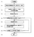
そこで制御部Contは図7に示すように感光体1の回転を制御して画像白抜けの発生の原因となる像流れを抑制する。図7は一つの感光体の回転制御だけを示しているが、制御部Contは印字動作に用いられる画像形成部のそれぞれの感光体について同様の回転制御を行なう。その場合、後述する制御目的を達成できるように、画像形成部ごとに制御タイミングがずらされる。
Therefore, the controller Cont controls the rotation of the
プリンター100は操作パネルPAでのユーザーからのプリント指示があったり、ネットワーク経由によるプリント指示を受信したら印字動作(トナー画像形成動作)を開始するため(S1)、感光体1を画像搬送方向(正転方向)に回転させる(S2)。この時に帯電器2による帯電出力を開始させ、画像パターン形成の準備を行う。
The
準備が完了したら、印字する画像パターンに応じて露光装置3から感光体1に画像露光を施し、感光体1上に静電潜像を形成し、これを現像装置4で可視トナー像とし、このトナー像を1次転写ローラー6で中間転写ベルト7に転写し、さらに2次転写ローラー8で記録シートSに2次転写する(S3)。要求される印字枚数分(画像形成枚数分)の、このようなパターン形成(印字動作)が終了したら、帯電器出力を停止させ、感光体1を停止させる(S4)。
When the preparation is completed, the
ステップS1から〜ステップS4に至る間で要した印字動作時間が所定時間T1以上であった場合は(S5)、所定時間T2待った後に(S6)、感光体1を画像搬送方向とは逆側(逆転方向)に所定時間T3回転させる(S7)。
If the printing operation time required from step S1 to step S4 is equal to or longer than the predetermined time T1 (S5), after waiting for the predetermined time T2 (S6), the
ここで所定時間T1は要求される印字枚数分のパターン形成に要した時間であり、「印字枚数(画像形成枚数)」と置き換えることができる時間である。 Here, the predetermined time T1 is a time required for pattern formation for the required number of printed sheets, and can be replaced with “number of printed sheets (number of formed images)”.
前記感光体1の逆回転は帯電器2近傍の放電性生物が付着する感光体1の部位をずらして変えることが目的である。そのため、1回の逆転時間は感光体1周分よりも短くてよく、図5に示すように、帯電器2による帯電幅wの移動距離が確保できる微小逆転角度θ又はそれを超える程度(少し大きいだけでもよい)の角度回ることができる時間でよい。
The purpose of the reverse rotation of the
感光体1をこのように逆回転させることで、クリーニングブレード51は図9(A)に示すクリーニング時の状態から、図9(B)に示すように、クリーニングブレード51の先端部511が感光体逆転方向になじんでブレード51の感光体1への押し当て力が逃げる方向になるため、感光体1とクリーニングブレード51とのこすれ音は非常に低減する。
By rotating the
印字終了後は他の動作音がないために、このこすれ音は非常に耳障りに聞こえるためにこのような感光体逆回転による静音化は非常に好ましい。
印字終了後から所定時間T4経過すると(S8)、放電性生物の濃度が低くなり感光体付着の影響が小さくなるため、所定時間T4経過までの間、所定時間間隔で感光体逆回転を繰り返す(S6、S7)。
Since there is no other operation sound after the end of printing, this rubbing sound is very harsh, so it is very preferable to reduce the noise by reverse rotation of the photosensitive member.
When the predetermined time T4 elapses from the end of printing (S8), the density of the dischargeable organisms becomes lower and the influence of adhesion of the photoconductor is reduced, so that the reverse rotation of the photoconductor is repeated at predetermined time intervals until the predetermined time T4 elapses ( S6, S7).
繰り返し感光体逆転を行う時間間隔は回転回数が少なくなる時間間隔である方が、静音化と、感光体1及びブレード51の耐久性の観点から望ましく、例えば次表に示す制御を挙げることができる。

印字動作時間T1が短いほど印字終了後に発生する放電生成物の量は少なくなる。そこで、印字動作時間に応じて逆転回数を変えることが可能である。具体的には、表に例示するように、1分未満では逆回転を行わず、1分以上〜10分未満では2回行うなどである。 The shorter the printing operation time T1, the smaller the amount of discharge products generated after printing is completed. Therefore, the number of reverse rotations can be changed according to the printing operation time. Specifically, as illustrated in the table, reverse rotation is not performed in less than 1 minute, and is performed twice in 1 to 10 minutes.
印字終了後から時間が経っていくと浮遊している放電生成物は、図示省略の放電生成物の吸引装置による吸引や他の箇所への付着などにより減少する。そのため、印字終了後からの時間経過に応じて逆回転の間隔を制御することができる。その場合も、表に例示すように、1回目は1分後、2回目は3分後と徐々に間隔を大きくしていく。 As time elapses from the end of printing, the floating discharge product decreases due to suction of the discharge product (not shown) by the suction device or adhesion to other locations. Therefore, the reverse rotation interval can be controlled in accordance with the passage of time from the end of printing. Also in this case, as shown in the table, the interval is gradually increased after 1 minute for the first time and 3 minutes for the second time.
こういった制御により逆回転を適切な回数に制限することで、静音化に加えクリーニングブレード51と感光体1の摩耗抑制も図ることができる。
By limiting the reverse rotation to an appropriate number of times through such control, it is possible to suppress wear of the
図8は印字終了後の感光体回転逆転制御例のタイムチャートを示している。
印字動作時T1は感光体を正回転させる。全ての画像形成終了後に感光体1を停止させる。印字終了時の感光体停止時より所定時間T2経過したら、感光体1を所定時間T31逆回転させ、クリーニングブレード51を図9(A)の状態から図9(B)の状態へ変え、食い込みを解除させる。
FIG. 8 shows a time chart of an example of the photosensitive member rotation reverse rotation control after the end of printing.
At the time of printing operation T1, the photosensitive member is rotated forward. After all the image formation is completed, the
この動作をその後の逆回転動作よりも低速で行うことで、クリーニングブレード51の感光体1との当接部511の破損を防止することができる。その後回転速度を切換えさらに所定時間T32逆回転させ帯電器2近傍の放電性生物が付着する感光体1の部位をずらす。時間T31とT32の合計が図7中のステップS7の、1回目逆転時の所定時間T3にあたる。
By performing this operation at a lower speed than the subsequent reverse rotation operation, the
その後も、印字終了時の感光体停止時より所定時間T2経過したら、所定時間T3逆回転させ、帯電器2近傍の放電性生物が付着する感光体1の部位を切り替える。2回目以降の逆転は、クリーニングブレード51が図9(B)の状態になっているので、時間帯T31のような低速回転は必要ない。
Thereafter, when the predetermined time T2 has elapsed from the time when the photoconductor is stopped at the end of printing, the reverse rotation is performed for the predetermined time T3 to switch the portion of the
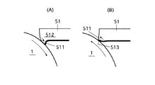
図10はクリーニングブレード51の他の例を示している。
このクリーニングブレード51はクリーニング性に優れたクリーニング部512と、クリーニング部512よりも摩擦係数が小さくこすれによる音が小さい静音部513とからなっている。
FIG. 10 shows another example of the
The
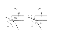
印字動作時は図10(A)に示した矢印の方向に感光体1が回転し、クリーニング部512が感光体1に接触する。印字終了後の逆回転時は図10(B)に示した矢印の方向に感光体1が逆転し、静音部513が感光体1に接触する。このような構成にすることで、印字動作時のクリーニング性能と印字終了後の逆回転時の静音化を両立させることができる。静音部513は摩擦係数の少ない材料で構成したり、クリーニング部512と同じ材料で、且つ、図11に示すように摩擦を低減する段差部514をつけた裏面形状にすることで構成することができる。
During the printing operation, the
感光体逆転制御を行なうにあたり、プリンター100の環境湿度を考慮してもよく、次表にその例を示す。このとき制御部Contは湿度センサs1から湿度情報を入手する。
In performing the photoreceptor reverse control, the environmental humidity of the
以上説明した画像形成装置はタンデム型のカラープリンタであったが、モノクロプリンター等の他のタイプのプリンターや複写機、ファクシミリ機など、さらにはこれらのうち2以上を組み合わせた複合機にも適用できる。 Although the image forming apparatus described above is a tandem type color printer, it can be applied to other types of printers such as monochrome printers, copiers, facsimile machines, etc. .
本発明は、感光体にトナー像を形成して最終的に記録シートに転写、定着させることができ、感光体をカウンター方式のクリーニングブレードでクリーニングする画像形成装置であって、感光体とクリーニングブレードの摩擦力を軽減して像流れ現象抑制のための感光体回転を行なうことができ、また、該摩擦力軽減により像流れ現象抑制のための感光体回転時の「異音」発生を抑制するとともに感光体とクリーニングブレードの長寿命化を図ることができる画像形成装置を提供することに利用できる。 The present invention is an image forming apparatus capable of forming a toner image on a photosensitive member and finally transferring and fixing the toner image on a recording sheet, and cleaning the photosensitive member with a counter type cleaning blade. The photosensitive member can be rotated to reduce the image friction phenomenon by reducing the frictional force of the image, and the generation of “abnormal noise” during the rotation of the photosensitive member to suppress the image flow phenomenon can be suppressed by reducing the frictional force. In addition, the present invention can be used to provide an image forming apparatus capable of extending the life of the photosensitive member and the cleaning blade.
100 プリンター(画像形成装置の1例)
Y、M、C、K 画像形成部
1 感光体
DY、DM、DC、DK 感光体駆動部
2 帯電器
w 帯電器幅
200 放電生成物
3 画像露光装置
4 現像装置
5 クリーニング装置
51 クリーニングブレード
511 ブレード先端部
512 クリーニング部
513 静音部
514 段差部
Cont 制御部
s1 湿度センサ
θ 感光体の微小逆転角度
100 Printer (an example of an image forming apparatus)
Y, M, C, K
Claims (9)
前記感光体を画像形成のための正転方向にも、該正転方向に対する逆転方向にも回転駆動可能な感光体駆動部と、
前記感光体駆動部の制御部を含んでおり、
前記制御部は、前記画像形成部でトナー像が形成され、該トナー像が記録シートに転写される画像形成動作の終了後の非画像形成動作時に、前記感光体駆動部に前記感光体を、前記帯電装置による放電生成物の前記感光体への局所的集中付着を抑制するように、前記帯電装置による帯電幅の移動距離が確保できる微小角度で逆転させることができることを特徴とする画像形成装置。 The surface of the photoconductor to be rotated is charged by a charging device, and an electrostatic latent image is formed on the surface of the photoconductor surface charged by the charging device according to the image to be formed to form an electrostatic latent image. The image forming unit includes at least one image forming unit that develops an electrostatic latent image by a developing device to form a visible toner image, and the toner image formed by the image forming unit can be transferred and fixed on a recording sheet. An image forming apparatus that cleans residuals including transfer residual toner on a photosensitive member of a part with a cleaning device, the cleaning device having a cleaning blade with which an elastic tip is brought into contact with the photosensitive member in a counter manner An image forming apparatus that employs a cleaning device,
A photoconductor drive unit capable of rotationally driving the photoconductor in a normal rotation direction for image formation and in a reverse direction with respect to the normal rotation direction;
Including a control unit of the photosensitive member driving unit,
In the non-image forming operation after completion of the image forming operation in which a toner image is formed in the image forming unit and the toner image is transferred to a recording sheet, the control unit is configured to put the photoconductor in the photoconductor driving unit. An image forming apparatus characterized in that it can be reversed at a very small angle that can secure a moving distance of the charging width by the charging device so as to suppress the local concentrated adhesion of the discharge product by the charging device to the photoreceptor. .
Priority Applications (1)
| Application Number | Priority Date | Filing Date | Title |
|---|---|---|---|
| JP2012083429A JP5862425B2 (en) | 2012-04-01 | 2012-04-01 | Image forming apparatus |
Applications Claiming Priority (1)
| Application Number | Priority Date | Filing Date | Title |
|---|---|---|---|
| JP2012083429A JP5862425B2 (en) | 2012-04-01 | 2012-04-01 | Image forming apparatus |
Publications (2)
| Publication Number | Publication Date |
|---|---|
| JP2013213886A JP2013213886A (en) | 2013-10-17 |
| JP5862425B2 true JP5862425B2 (en) | 2016-02-16 |
Family
ID=49587265
Family Applications (1)
| Application Number | Title | Priority Date | Filing Date |
|---|---|---|---|
| JP2012083429A Active JP5862425B2 (en) | 2012-04-01 | 2012-04-01 | Image forming apparatus |
Country Status (1)
| Country | Link |
|---|---|
| JP (1) | JP5862425B2 (en) |
Cited By (1)
| Publication number | Priority date | Publication date | Assignee | Title |
|---|---|---|---|---|
| EP4579352A1 (en) * | 2023-12-25 | 2025-07-02 | FUJIFILM Business Innovation Corp. | Image forming apparatus |
Families Citing this family (2)
| Publication number | Priority date | Publication date | Assignee | Title |
|---|---|---|---|---|
| JP6921558B2 (en) * | 2017-02-28 | 2021-08-18 | キヤノン株式会社 | Image forming device |
| JP7246901B2 (en) * | 2018-11-27 | 2023-03-28 | キヤノン株式会社 | image forming device |
Family Cites Families (17)
| Publication number | Priority date | Publication date | Assignee | Title |
|---|---|---|---|---|
| JPH09292761A (en) * | 1996-02-28 | 1997-11-11 | Fuji Xerox Co Ltd | Image forming device |
| JP4562017B2 (en) * | 2000-07-13 | 2010-10-13 | 株式会社リコー | Image carrier rotation control device, image carrier rotation control method, and image forming apparatus |
| JP2003015491A (en) * | 2001-06-28 | 2003-01-17 | Canon Inc | Image forming device |
| JP2004102178A (en) * | 2002-09-12 | 2004-04-02 | Fuji Xerox Co Ltd | Image forming apparatus and cleaning device |
| JP2004287316A (en) * | 2003-03-25 | 2004-10-14 | Konica Minolta Holdings Inc | Image forming apparatus |
| JP2005077575A (en) * | 2003-08-29 | 2005-03-24 | Kyocera Mita Corp | Image forming device |
| JP2005077576A (en) * | 2003-08-29 | 2005-03-24 | Kyocera Mita Corp | Image forming apparatus |
| JP4285168B2 (en) * | 2003-09-24 | 2009-06-24 | コニカミノルタビジネステクノロジーズ株式会社 | Image forming apparatus |
| JP4305334B2 (en) * | 2004-08-31 | 2009-07-29 | コニカミノルタビジネステクノロジーズ株式会社 | Image forming apparatus |
| JP2006072172A (en) * | 2004-09-06 | 2006-03-16 | Ricoh Co Ltd | Image forming apparatus |
| JP2007333810A (en) * | 2006-06-12 | 2007-12-27 | Konica Minolta Business Technologies Inc | Image forming apparatus and image forming method |
| JP4985133B2 (en) * | 2007-06-15 | 2012-07-25 | コニカミノルタビジネステクノロジーズ株式会社 | Image forming apparatus and image forming method |
| JP2010002436A (en) * | 2008-06-18 | 2010-01-07 | Konica Minolta Business Technologies Inc | Charger and image forming apparatus |
| US20100111566A1 (en) * | 2008-11-06 | 2010-05-06 | Kabushiki Kaisha Toshiba | Photoconductive drums controller |
| JP5262881B2 (en) * | 2009-03-18 | 2013-08-14 | コニカミノルタビジネステクノロジーズ株式会社 | Image forming apparatus, image forming apparatus control method, and image forming apparatus control program |
| JP5494945B2 (en) * | 2010-01-27 | 2014-05-21 | 株式会社リコー | Image forming apparatus |
| JP2012013718A (en) * | 2010-06-29 | 2012-01-19 | Konica Minolta Business Technologies Inc | Image forming device |
-
2012
- 2012-04-01 JP JP2012083429A patent/JP5862425B2/en active Active
Cited By (1)
| Publication number | Priority date | Publication date | Assignee | Title |
|---|---|---|---|---|
| EP4579352A1 (en) * | 2023-12-25 | 2025-07-02 | FUJIFILM Business Innovation Corp. | Image forming apparatus |
Also Published As
| Publication number | Publication date |
|---|---|
| JP2013213886A (en) | 2013-10-17 |
Similar Documents
| Publication | Publication Date | Title |
|---|---|---|
| JP6264643B2 (en) | Image forming apparatus | |
| CN102269953B (en) | Image forming apparatus | |
| JP2013182153A (en) | Image forming apparatus | |
| JP2012233994A (en) | Image forming apparatus | |
| JP5862425B2 (en) | Image forming apparatus | |
| JP2012123251A (en) | Image forming apparatus | |
| JP4929829B2 (en) | Image forming apparatus | |
| JP7013734B2 (en) | Image forming device and process cartridge | |
| JP4766091B2 (en) | Image forming apparatus | |
| JP2005250215A (en) | Image forming apparatus and method | |
| JP5267930B2 (en) | Scorotron charging device, image forming apparatus and process cartridge | |
| JP2012194493A (en) | Image forming apparatus | |
| JP3839979B2 (en) | Image forming apparatus | |
| JP2022114924A (en) | image forming device | |
| JP4821295B2 (en) | Image forming apparatus | |
| JP2013222110A (en) | Image forming apparatus | |
| JP2013140293A (en) | Image forming apparatus | |
| JP4947067B2 (en) | Image forming apparatus | |
| JP5251636B2 (en) | Image forming apparatus | |
| JP5814706B2 (en) | Image forming apparatus | |
| JP2007024999A (en) | Image forming apparatus | |
| JP2008209602A (en) | Image forming apparatus | |
| JP2007248547A (en) | Image forming apparatus | |
| JP2007240922A (en) | Image forming apparatus | |
| JP2008310056A (en) | Electrifying roller and image forming apparatus |
Legal Events
| Date | Code | Title | Description |
|---|---|---|---|
| A621 | Written request for application examination |
Free format text: JAPANESE INTERMEDIATE CODE: A621 Effective date: 20141118 |
|
| A977 | Report on retrieval |
Free format text: JAPANESE INTERMEDIATE CODE: A971007 Effective date: 20150909 |
|
| A131 | Notification of reasons for refusal |
Free format text: JAPANESE INTERMEDIATE CODE: A131 Effective date: 20150915 |
|
| A521 | Written amendment |
Free format text: JAPANESE INTERMEDIATE CODE: A523 Effective date: 20151112 |
|
| TRDD | Decision of grant or rejection written | ||
| A01 | Written decision to grant a patent or to grant a registration (utility model) |
Free format text: JAPANESE INTERMEDIATE CODE: A01 Effective date: 20151201 |
|
| A61 | First payment of annual fees (during grant procedure) |
Free format text: JAPANESE INTERMEDIATE CODE: A61 Effective date: 20151214 |
|
| R150 | Certificate of patent or registration of utility model |
Ref document number: 5862425 Country of ref document: JP Free format text: JAPANESE INTERMEDIATE CODE: R150 |