JP6921558B2 - Image forming device - Google Patents
Image forming device Download PDFInfo
- Publication number
- JP6921558B2 JP6921558B2 JP2017037733A JP2017037733A JP6921558B2 JP 6921558 B2 JP6921558 B2 JP 6921558B2 JP 2017037733 A JP2017037733 A JP 2017037733A JP 2017037733 A JP2017037733 A JP 2017037733A JP 6921558 B2 JP6921558 B2 JP 6921558B2
- Authority
- JP
- Japan
- Prior art keywords
- toner
- image
- intermediate transfer
- amount
- transfer member
- Prior art date
- Legal status (The legal status is an assumption and is not a legal conclusion. Google has not performed a legal analysis and makes no representation as to the accuracy of the status listed.)
- Active
Links
Images


Classifications
-
- G—PHYSICS
- G03—PHOTOGRAPHY; CINEMATOGRAPHY; ANALOGOUS TECHNIQUES USING WAVES OTHER THAN OPTICAL WAVES; ELECTROGRAPHY; HOLOGRAPHY
- G03G—ELECTROGRAPHY; ELECTROPHOTOGRAPHY; MAGNETOGRAPHY
- G03G15/00—Apparatus for electrographic processes using a charge pattern
- G03G15/06—Apparatus for electrographic processes using a charge pattern for developing
- G03G15/08—Apparatus for electrographic processes using a charge pattern for developing using a solid developer, e.g. powder developer
- G03G15/0801—Apparatus for electrographic processes using a charge pattern for developing using a solid developer, e.g. powder developer for cascading
-
- G—PHYSICS
- G03—PHOTOGRAPHY; CINEMATOGRAPHY; ANALOGOUS TECHNIQUES USING WAVES OTHER THAN OPTICAL WAVES; ELECTROGRAPHY; HOLOGRAPHY
- G03G—ELECTROGRAPHY; ELECTROPHOTOGRAPHY; MAGNETOGRAPHY
- G03G15/00—Apparatus for electrographic processes using a charge pattern
- G03G15/06—Apparatus for electrographic processes using a charge pattern for developing
- G03G15/08—Apparatus for electrographic processes using a charge pattern for developing using a solid developer, e.g. powder developer
- G03G15/0822—Arrangements for preparing, mixing, supplying or dispensing developer
- G03G15/0848—Arrangements for testing or measuring developer properties or quality, e.g. charge, size, flowability
- G03G15/0849—Detection or control means for the developer concentration
- G03G15/0851—Detection or control means for the developer concentration the concentration being measured by electrical means
-
- G—PHYSICS
- G03—PHOTOGRAPHY; CINEMATOGRAPHY; ANALOGOUS TECHNIQUES USING WAVES OTHER THAN OPTICAL WAVES; ELECTROGRAPHY; HOLOGRAPHY
- G03G—ELECTROGRAPHY; ELECTROPHOTOGRAPHY; MAGNETOGRAPHY
- G03G15/00—Apparatus for electrographic processes using a charge pattern
- G03G15/01—Apparatus for electrographic processes using a charge pattern for producing multicoloured copies
- G03G15/0105—Details of unit
- G03G15/0131—Details of unit for transferring a pattern to a second base
- G03G15/0136—Details of unit for transferring a pattern to a second base transfer member separable from recording member or vice versa, mode switching
-
- G—PHYSICS
- G03—PHOTOGRAPHY; CINEMATOGRAPHY; ANALOGOUS TECHNIQUES USING WAVES OTHER THAN OPTICAL WAVES; ELECTROGRAPHY; HOLOGRAPHY
- G03G—ELECTROGRAPHY; ELECTROPHOTOGRAPHY; MAGNETOGRAPHY
- G03G15/00—Apparatus for electrographic processes using a charge pattern
- G03G15/01—Apparatus for electrographic processes using a charge pattern for producing multicoloured copies
- G03G15/0142—Structure of complete machines
- G03G15/0147—Structure of complete machines using a single reusable electrographic recording member
- G03G15/0152—Structure of complete machines using a single reusable electrographic recording member onto which the monocolour toner images are superposed before common transfer from the recording member
- G03G15/0173—Structure of complete machines using a single reusable electrographic recording member onto which the monocolour toner images are superposed before common transfer from the recording member plural rotations of recording member to produce multicoloured copy, e.g. rotating set of developing units
-
- G—PHYSICS
- G03—PHOTOGRAPHY; CINEMATOGRAPHY; ANALOGOUS TECHNIQUES USING WAVES OTHER THAN OPTICAL WAVES; ELECTROGRAPHY; HOLOGRAPHY
- G03G—ELECTROGRAPHY; ELECTROPHOTOGRAPHY; MAGNETOGRAPHY
- G03G15/00—Apparatus for electrographic processes using a charge pattern
- G03G15/01—Apparatus for electrographic processes using a charge pattern for producing multicoloured copies
- G03G15/0142—Structure of complete machines
- G03G15/0178—Structure of complete machines using more than one reusable electrographic recording member, e.g. one for every monocolour image
- G03G15/0189—Structure of complete machines using more than one reusable electrographic recording member, e.g. one for every monocolour image primary transfer to an intermediate transfer belt
-
- G—PHYSICS
- G03—PHOTOGRAPHY; CINEMATOGRAPHY; ANALOGOUS TECHNIQUES USING WAVES OTHER THAN OPTICAL WAVES; ELECTROGRAPHY; HOLOGRAPHY
- G03G—ELECTROGRAPHY; ELECTROPHOTOGRAPHY; MAGNETOGRAPHY
- G03G15/00—Apparatus for electrographic processes using a charge pattern
- G03G15/01—Apparatus for electrographic processes using a charge pattern for producing multicoloured copies
- G03G15/0142—Structure of complete machines
- G03G15/0178—Structure of complete machines using more than one reusable electrographic recording member, e.g. one for every monocolour image
- G03G15/0194—Structure of complete machines using more than one reusable electrographic recording member, e.g. one for every monocolour image primary transfer to the final recording medium
-
- G—PHYSICS
- G03—PHOTOGRAPHY; CINEMATOGRAPHY; ANALOGOUS TECHNIQUES USING WAVES OTHER THAN OPTICAL WAVES; ELECTROGRAPHY; HOLOGRAPHY
- G03G—ELECTROGRAPHY; ELECTROPHOTOGRAPHY; MAGNETOGRAPHY
- G03G15/00—Apparatus for electrographic processes using a charge pattern
- G03G15/50—Machine control of apparatus for electrographic processes using a charge pattern, e.g. regulating differents parts of the machine, multimode copiers, microprocessor control
- G03G15/5033—Machine control of apparatus for electrographic processes using a charge pattern, e.g. regulating differents parts of the machine, multimode copiers, microprocessor control by measuring the photoconductor characteristics, e.g. temperature, or the characteristics of an image on the photoconductor
- G03G15/5041—Detecting a toner image, e.g. density, toner coverage, using a test patch
-
- G—PHYSICS
- G03—PHOTOGRAPHY; CINEMATOGRAPHY; ANALOGOUS TECHNIQUES USING WAVES OTHER THAN OPTICAL WAVES; ELECTROGRAPHY; HOLOGRAPHY
- G03G—ELECTROGRAPHY; ELECTROPHOTOGRAPHY; MAGNETOGRAPHY
- G03G21/00—Arrangements not provided for by groups G03G13/00 - G03G19/00, e.g. cleaning, elimination of residual charge
- G03G21/0005—Arrangements not provided for by groups G03G13/00 - G03G19/00, e.g. cleaning, elimination of residual charge for removing solid developer or debris from the electrographic recording medium
- G03G21/0011—Arrangements not provided for by groups G03G13/00 - G03G19/00, e.g. cleaning, elimination of residual charge for removing solid developer or debris from the electrographic recording medium using a blade; Details of cleaning blades, e.g. blade shape, layer forming
-
- G—PHYSICS
- G03—PHOTOGRAPHY; CINEMATOGRAPHY; ANALOGOUS TECHNIQUES USING WAVES OTHER THAN OPTICAL WAVES; ELECTROGRAPHY; HOLOGRAPHY
- G03G—ELECTROGRAPHY; ELECTROPHOTOGRAPHY; MAGNETOGRAPHY
- G03G15/00—Apparatus for electrographic processes using a charge pattern
- G03G15/14—Apparatus for electrographic processes using a charge pattern for transferring a pattern to a second base
- G03G15/16—Apparatus for electrographic processes using a charge pattern for transferring a pattern to a second base of a toner pattern, e.g. a powder pattern, e.g. magnetic transfer
- G03G15/1605—Apparatus for electrographic processes using a charge pattern for transferring a pattern to a second base of a toner pattern, e.g. a powder pattern, e.g. magnetic transfer using at least one intermediate support
- G03G15/161—Apparatus for electrographic processes using a charge pattern for transferring a pattern to a second base of a toner pattern, e.g. a powder pattern, e.g. magnetic transfer using at least one intermediate support with means for handling the intermediate support, e.g. heating, cleaning, coating with a transfer agent
-
- G—PHYSICS
- G03—PHOTOGRAPHY; CINEMATOGRAPHY; ANALOGOUS TECHNIQUES USING WAVES OTHER THAN OPTICAL WAVES; ELECTROGRAPHY; HOLOGRAPHY
- G03G—ELECTROGRAPHY; ELECTROPHOTOGRAPHY; MAGNETOGRAPHY
- G03G15/00—Apparatus for electrographic processes using a charge pattern
- G03G15/50—Machine control of apparatus for electrographic processes using a charge pattern, e.g. regulating differents parts of the machine, multimode copiers, microprocessor control
- G03G15/5016—User-machine interface; Display panels; Control console
Description
本発明は、電子写真方式、静電記録方式等によって像担持体上に形成された静電潜像を現像して可視画像を形成する現像装置を備えた、複写機、プリンタ、記録画像表示装置、ファクシミリ等の画像形成装置に関する。 The present invention includes a copier, a printer, and a recorded image display device provided with a developing device for developing an electrostatic latent image formed on an image carrier by an electrophotographic method, an electrostatic recording method, or the like to form a visible image. , Facsimile and other image forming devices.
イエロー、マゼンタ、シアン、ブラックのトナー像を形成する画像形成ユニットをそれぞれ中間転写ベルトに対向配置し、各画像形成ユニットが中間転写ベルトに接触してカラー画像を形成するタンデム型の画像形成装置がある。このような画像形成装置において、ブラックのトナーを用いて白黒画像を出力する際に、使用しないイエロー、マゼンタ、シアンの画像形成ユニットを中間転写ベルトから離間する構成がある。この構成において、厚さのある記録材に画像を形成する際に、この記録材が中間転写ベルトから画像が転写される転写部に突入する際に生ずるショックが、中間転写ベルトに伝達する。その結果、画像に影響を与えることがある。それに対して、更なる画質の向上のために、厚さのある記録材に画像を形成する際には、使用しない画像形成ユニットを中間転写ベルトに接触させて、ショックを緩和する技術が挙げられる(特許文献1)。 A tandem type image forming apparatus in which image forming units forming yellow, magenta, cyan, and black toner images are arranged facing each other on an intermediate transfer belt, and each image forming unit contacts an intermediate transfer belt to form a color image. be. In such an image forming apparatus, when a black and white image is output using black toner, the unused yellow, magenta, and cyan image forming units are separated from the intermediate transfer belt. In this configuration, when an image is formed on a thick recording material, the shock generated when the recording material rushes into the transfer portion from which the image is transferred from the intermediate transfer belt is transmitted to the intermediate transfer belt. As a result, the image may be affected. On the other hand, in order to further improve the image quality, when forming an image on a thick recording material, there is a technique of bringing an unused image forming unit into contact with an intermediate transfer belt to alleviate the shock. (Patent Document 1).
この構成では、使用しない画像形成ユニットの感光ドラムは回転を続けることになるため、クリーニングブレードと感光ドラム間の摩擦が大きくなり、クリーニングブレードと感光ドラムの摺擦性が低下する。それを回避するために、所定の間隔でトナー帯をクリーニングブレードに供給する構成が挙げられる。 In this configuration, since the photosensitive drum of the unused image forming unit continues to rotate, the friction between the cleaning blade and the photosensitive drum increases, and the rubbing property between the cleaning blade and the photosensitive drum decreases. In order to avoid this, there is a configuration in which toner bands are supplied to the cleaning blade at predetermined intervals.
しかし、画像形成ユニットのトナーがトナー帯を形成できる量を下回った場合に、継続して白黒画像を形成し続けるとクリーニングブレードに悪影響を与えやすい。これを回避するために、トナーが補給されるまで画像形成を停止すると、長いダウンタイムが生ずることになり、出力を要求するユーザに対してユーザビリティーの低下につながる。 However, when the amount of toner in the image forming unit is less than the amount capable of forming a toner band, if the black-and-white image is continuously formed, the cleaning blade is likely to be adversely affected. To avoid this, if the image formation is stopped until the toner is replenished, a long downtime will occur, which will lead to a decrease in usability for the user who requests the output.
そのため、トナー帯を形成できないことによるクリーニングブレードへの影響を小さくしながら、出力を要求するユーザへのユーザビリティーの向上を図る構成が望まれている。 Therefore, it is desired to improve the usability for the user who requests the output while reducing the influence on the cleaning blade due to the inability to form the toner band.
上記目的を達成するために本発明の一態様に係る画像形成装置は以下のような構成を備える。即ち、記録材に画像を形成する画像形成装置であって、中間転写部材と、第1の像担持体と、前記第1の像担持体に形成された静電潜像を色トナーを用いて現像する第1の現像装置と、前記中間転写部材にトナー画像を転写後に前記第1の像担持体に残留した色トナーを除去する第1のクリーニングブレードと、を含む第1の画像形成部と、第2の像担持体と、前記第2の像担持体に形成された静電潜像を黒トナーを用いて現像する第2の現像装置と、前記中間転写部材にトナー画像を転写後に前記第2の像担持体に残留した黒トナーを除去する第2のクリーニングブレードと、を含む第2の画像形成部と、前記第1の像担持体が前記中間転写部材に接触し且つ前記第2の像担持体が前記中間転写部材に接触している第1の状態と、前記第1の像担持体が前記中間転写部材から離間し且つ前記第2の像担持体が前記中間転写部材に接触している第2の状態との間で切り替え可能な当接離間機構と、黒単色で記録材に画像を形成する際、前記第1の状態において前記第1の現像装置が前記第1のクリーニングブレードに供給するためのトナー画像を形成し且つ前記第2の画像形成部が当該記録材に転写されるトナー画像を形成する第1の黒単色モードと、前記第2の状態において前記第2の画像形成部が当該記録材に転写されるトナー画像を形成する第2の黒単色モードと、を含む複数のモードの中から1つのモードを選択して画像形成を実行可能な実行部と、前記第1の現像装置内のトナー量に関する情報を検知する検知部と、操作部と、を備え、前記実行部は、前記第1の黒単色モードで画像形成を実行している間に、前記検知部により検知された前記情報が前記第1の現像装置内のトナー量が所定量よりも少ないことを示す場合には、画像形成を中断し、且つ前記第1の黒単色モードから前記第2の黒単色モードに切り替えて画像形成を再開させる指示を受け付けるための画面を前記操作部に表示させ、前記操作部を介して前記指示を受け付けた場合には、前記第1の黒単色モードから前記第2の黒単色モードに切り替えて画像形成を再開し、前記操作部を介して前記指示を受け付けなかった場合には、前記第1の現像装置内のトナー量が前記所定量に達するまで画像形成の中断を継続し、前記第1の現像装置にトナーが供給されて前記第1の現像装置内のトナー量が前記所定量に達したら前記第1の黒単色モードで画像形成を再開することを特徴とする。In order to achieve the above object, the image forming apparatus according to one aspect of the present invention has the following configuration. That is, it is an image forming apparatus that forms an image on a recording material, and uses colored toner to form an intermediate transfer member, a first image carrier, and an electrostatic latent image formed on the first image carrier. A first image forming unit including a first developing apparatus for developing and a first cleaning blade for removing color toner remaining on the first image carrier after transferring a toner image to the intermediate transfer member. , The second image carrier, the second developing device that develops the electrostatic latent image formed on the second image carrier with black toner, and the intermediate transfer member after transferring the toner image. A second image forming section including a second cleaning blade for removing black toner remaining on the second image carrier, and the first image carrier come into contact with the intermediate transfer member and the second image carrier. The first state in which the image carrier is in contact with the intermediate transfer member, and the first image carrier is separated from the intermediate transfer member and the second image carrier is in contact with the intermediate transfer member. When an image is formed on a recording material in a single black color and a contact separation mechanism that can be switched between the second state and the second state, the first developing apparatus performs the first cleaning in the first state. A first black monochromatic mode in which a toner image to be supplied to a blade is formed and a toner image in which the second image forming unit is transferred to the recording material is formed, and in the second state, the second An execution unit capable of performing image formation by selecting one mode from a plurality of modes including a second black monochromatic mode in which the image forming unit forms a toner image transferred to the recording material, and the above. A detection unit for detecting information on the amount of toner in the first developing apparatus and an operation unit are provided, and the execution unit detects the detection while executing image formation in the first black monochromatic mode. When the information detected by the unit indicates that the amount of toner in the first developing apparatus is less than a predetermined amount, the image formation is interrupted and the first black monochromatic mode is changed to the second. When the operation unit is displayed with a screen for receiving an instruction to switch to the black monochromatic mode and resume image formation, and the instruction is received via the operation unit, the first black monochromatic mode is changed to the first. When the image formation is restarted by switching to the black monochromatic mode of 2 and the instruction is not received via the operation unit, the image formation is performed until the amount of toner in the first developing apparatus reaches the predetermined amount. When the interruption is continued and the toner is supplied to the first developing apparatus and the amount of toner in the first developing apparatus reaches the predetermined amount, the image is imaged in the first black monochromatic mode. It is characterized by resuming image formation.
本発明により、トナー帯を形成できないことによるクリーニングブレードへの影響を小さくしながら、出力を要求するユーザへのユーザビリティーの向上を図ることができる。 INDUSTRIAL APPLICABILITY According to the present invention, it is possible to improve usability for a user who requires output while reducing the influence on the cleaning blade due to the inability to form a toner band.
以下に、本発明を実施するための形態について説明する。本実施例に記載する装置の構成や手段は本発明を説明するための一例であり、記載される内容に限定されるものではない。 Hereinafter, embodiments for carrying out the present invention will be described. The configuration and means of the apparatus described in this embodiment are examples for explaining the present invention, and are not limited to the contents described.
1.画像形成装置の全体的な構成及び動作
図1は本発明の実施形態に係る画像形成システム主要部の縦断面構造を示す構成図である。この画像形成装置10は、4つの感光ドラム(像担持体)209をタンデムに配置した中間転写方式の、フルカラー画像を形成することができる画像形成装置である。
1. 1. Overall Configuration and Operation of the Image Forming Device FIG. 1 is a configuration diagram showing a vertical cross-sectional structure of a main part of an image forming system according to an embodiment of the present invention. The
<画像読み取りプロセス>
図1の画像形成装置10は、原稿から画像を読み取るイメージリーダ20及び読み取った画像を用紙上に形成する印刷部30を備えている。原稿給送装置200は、原稿トレイ201上に上向きにセットされた原稿を先頭頁から順に1枚ずつ図1左方向へ給紙する。そして、湾曲したパスを通過してプラテンガラス219上を左からホームポジションにあるスキャナユニット202を経て右へ搬送し、その後、排紙トレイ220に向けて排出する。
<Image reading process>
The
この原稿がプラテンガラス219上のスキャナユニット202のホームポジションを左から右へ向けて通過するときに、原稿画像がホームポジションに記憶されたスキャナユニット202により読み取られる。
When this document passes through the home position of the
原稿がスキャナユニット202のホームポジションを通過する際に、原稿の読取面がスキャナユニット202の光で照射され、その原稿からの反射光がミラー203、204、205を介してレンズ206に導かれる。このレンズ206を通過した光は、イメージセンサ207の撮像面に結像する。
When the document passes through the home position of the
スキャナユニット202のホームポジションを左から右へ通過するように原稿を搬送することによって、原稿の搬送方向に対して直行する方向を主走査方向とし、搬送方向を副走査方向とする原稿読み取り操作が行われている。原稿がスキャナユニット202のホームポジションを通過する際に、主走査方向に原稿画像を1ライン毎にイメージセンサ207で読み取りながら、原稿を副走査方向に搬送することによって原稿画像全体の読み取りを行う。光学的に読み取られた画像は、イメージセンサ207によって画像データに変換されて出力される。イメージセンサ207から出力された画像データは、印刷部30の露光部208にビデオ信号として入力される。
By transporting the document so as to pass through the home position of the
なお、原稿給送装置200により原稿をプラテンガラス219上に搬送して所定位置に停止させ、この状態でスキャナユニット202を左から右へ走査させることにより原稿を読み取ることも可能である。この読み取り方法は、いわゆる原稿固定読みと呼ばれる方法である。
It is also possible to read the document by transporting the document onto the
原稿給送装置200を使用しないで原稿を読み取るときには、まず、ユーザにより原稿給送装置200を持ち上げてプラテンガラス219上に原稿を載置する。そして、スキャナユニット202を左から右へ走査させることにより原稿の読み取りを行う。原稿給送装置200を使用しないで原稿を読み取るときには、原稿固定読みが行われる。
When reading a document without using the
<作像プロセス>
本実施例では、イエロー(Y)の画像形成ユニット(第一画像形成ユニット)、ブラック(K)の画像形成ユニット(第二画像形成ユニット)、マゼンタ(M)の画像形成ユニット(第三画像形成ユニット)、シアン(C)の画像形成ユニット(第四画像形成ユニット)を有する。以下に説明する符号は、YMCK共通の構成であり、図1に示すようにイエロー用の構成はY,マゼンタ用の構成はM、シアン用の構成はC,ブラック用の構成はKの符号が追加されて示される。カラーモードの場合はYMCK全てで画像形成動作対象となり、モノクロモードの場合は基本的にKのみが画像形成動作する。印刷部30の露光部208は、イメージリーダ20から入力されたビデオ信号に基づきレーザ光を変調して出力する。レーザ光は、帯電器233によって帯電した感光ドラム209上に照射される。感光ドラム209には走査されたレーザ光に応じた静電潜像が形成される。ここで、露光部208は、原稿固定読み時には、正立画像(鏡像でない画像)が形成されるようにレーザ光を出力する。この感光ドラム209上の静電潜像は、現像装置212の現像スリーブによって供給されるトナーによってトナー像として可視像化される。感光ドラム209に形成されたトナー像は一次転写部で、後述する中間転写ベルトに転写される。中間転写ベルトへの転写後に感光ドラム209上に残留したトナーは、クリーニングブレード210を有するクリーニング装置に回収される。
<Image formation process>
In this embodiment, the yellow (Y) image forming unit (first image forming unit), the black (K) image forming unit (second image forming unit), and the magenta (M) image forming unit (third image forming). It has a unit) and a cyan (C) image forming unit (fourth image forming unit). The reference numerals described below are common to YMCK, and as shown in FIG. 1, the symbols for yellow are Y, the configuration for magenta is M, the configuration for cyan is C, and the configuration for black is K. Shown in addition. In the color mode, all YMCKs are subject to image formation operation, and in the monochrome mode, basically only K performs image formation operation. The exposure unit 208 of the
現像装置212の内部には、トナーとキャリアからなる二成分の現像剤が収容されており、現像剤に占めるトナーの重量で示した割合(トナー濃度)は8%である。なお、トナー濃度は、トナー帯電量、キャリア粒径、現像装置212の構造等で適正に調整されるべきものであるから、8%に限定されるものではない。トナーが消費されることにより、現像容器内のトナー濃度が変化し、その結果トナー帯電量の変化による濃度変動や感光ドラムへとキャリアが付着するキャリア付着などが発生する。このため、現像装置内のトナー濃度を正確に検知し、それに応じて補給を行うことで一定の画像品位を保っている。 A two-component developer composed of a toner and a carrier is housed inside the developing device 212, and the ratio (toner concentration) indicated by the weight of the toner to the developing agent is 8%. The toner concentration is not limited to 8% because it should be appropriately adjusted by the toner charge amount, the carrier particle size, the structure of the developing device 212, and the like. As the toner is consumed, the toner concentration in the developing container changes, and as a result, the density fluctuates due to the change in the toner charge amount, and the carrier adheres to the photosensitive drum. Therefore, a constant image quality is maintained by accurately detecting the toner concentration in the developing device and supplying the toner in accordance with the detection.
本実施例においては、トナー濃度を検出する方法として現像装置212に現像剤中の見かけの透磁率変化を検知するインダクタンスセンサ252が設置されている。毎プリントごとに前記インダクセンサ252にて現像器内の現像剤のトナー濃度を検出して目標トナー濃度と比較し、その結果に応じてトナー補給量を決定している。
In this embodiment, as a method of detecting the toner concentration, an
目標トナー濃度は、予め定められたものでもよいし現像器を初期設置するときに算出するものであってもよいが本実施例では予め定められた値とした。 The target toner concentration may be a predetermined value or a value calculated at the time of initial installation of the developing device, but in this embodiment, it is set to a predetermined value.
<トナー補給プロセス>
図1に示すように、トナー供給装置250が装置本体の上部に取りつけられている。トナー供給装置250の機能としては、現像器212へのトナーの供給と、トナーカートリッジ251からトナー供給装置250自身へのトナーの補給を行うものである。トナー供給装置250の画像形成装置本体における配置としては、現像器212へトナーを供給するための機能があるため、現像器212へトナーを供給可能なように、その上部にトナー供給装置250が配置されている。
<Toner replenishment process>
As shown in FIG. 1, the toner supply device 250 is attached to the upper part of the device main body. The functions of the toner supply device 250 are to supply toner to the developing device 212 and to supply toner from the toner cartridge 251 to the toner supply device 250 itself. As the arrangement of the toner supply device 250 in the image forming apparatus main body, since there is a function for supplying toner to the developer 212, the toner supply device 250 is arranged above the toner supply device 250 so that the toner can be supplied to the developer 212. Has been done.
トナー供給装置250の側面における断面図を図2に示す。図2に示すように、トナー供給装置250の構成としてトナーカートリッジ251がトナー供給装置250供給口にセットされる。トナーカートリッジ251からのトナーをトナー貯蔵部18に貯蔵する。貯蔵されたトナーをトナー供給装置250内のスクリュー(攪拌スクリュー11、第1のスクリュー12、第2のスクリュー13)によって現像器212へと搬送する構成となっている。また、トナーカートリッジ251からのトナーの補給する際は、供給口開閉機構Bがトナーカートリッジ251の先端に設けられたキャップ15と係合することによってトナーカートリッジ251が回転可能となる。そして、トナーカートリッジ251を回転させることでトナーを補給することができる構成になっている。
A cross-sectional view of the side surface of the toner supply device 250 is shown in FIG. As shown in FIG. 2, the toner cartridge 251 is set in the toner supply device 250 supply port as a configuration of the toner supply device 250. The toner from the toner cartridge 251 is stored in the
次に、トナー供給装置250のトナー貯蔵部の詳細について説明する。トナー供給装置250内のトナーは通常はトナーによってトナー貯蔵部18が満たされた状態にある。トナー貯蔵部18にはトナーセンサ17が設けられており、このトナーセンサ17の表面上にトナーが存在すると、トナーの圧力を感知し、トナー供給装置250内にトナーが存在する状態と認識する。一方で、現像器212への補給を行い、トナー貯蔵部18のトナーが消費されてくると、トナーセンサ17表面上のトナーが存在しなくなりトナー供給装置250内にトナーが無状態と認識する。その際、トナー貯蔵部18のトナーが存在する状態までトナーカートリッジ251からトナーが供給される。トナーカートリッジ251はそれ自体に螺旋形状が形成されたボトル形状をしており、トナーカートリッジ251自身が回転するする。それにより、カートリッジ内部に収容しているトナーがカートリッジの供給口まで搬送され、排出されることで、トナー貯蔵部18へとトナーを供給することができる。
Next, the details of the toner storage unit of the toner supply device 250 will be described. The toner in the toner supply device 250 is usually in a state where the
<転写プロセス>
中間転写体としての中間転写ベルト230は、無端ベルト状のフィルムで構成され、複数の張架部材としての駆動ローラ228、テンションローラ229、二次転写対向ローラ231に張架されている。中間転写ベルト230は、駆動ローラ228によって時計回りに回転駆動される。中間転写ベルト230の内周面側において、各感光ドラム209に対向する位置に、一次転写ローラ211が配置されている。一次転写ローラ211は、中間転写ベルト230を介して感光ドラム209に押圧され、中間転写ベルト230と感光ドラム209とが接触する一次転写部(一次転写ニップ)が形成されている。一次転写部により、感光ドラム209によって形成されたトナー像が中間転写ベルト230に一次転写される。また、中間転写ベルト230の外周面側において、二次転写対向ローラ231に対向する位置には、二次転写手段としてのローラ型の転写部材とされた二次転写ローラ232が配置されている。二次転写ローラ232は、中間転写ベルト230を介して二次転写対向ローラ232に押圧され、中間転写ベルト230と二次転写ローラ231とが接触する二次転写部(二次転写ニップ)が形成されている。この二次転写部によって中間転写体上のトナー像が用紙に転写されることになる。
<Transfer process>
The
<給紙プロセス>
一方、印刷部30内に装備されている上カセット215或いは下カセット216からピックアップローラ213、214により給紙された用紙は、縦パスローラ221によりレジストローラ222まで搬送される。レジ前センサ223で用紙の先端を検出し、レジストローラ222まで達したところで用紙を一旦停止する。また、手差しトレイ224から手差しピックアップローラ217により給紙された用紙においても同様にレジストローラ222まで搬送される。手差しトレイ224には手差しトレイ上の用紙の有無を検出するための手差しトレイ用紙検知センサと手差しトレイ上の用紙の送り方向のサイズを検出するための長さ検出センサ、用紙の搬送方向と直交する幅方向のサイズを検知する幅検知センサを備える。
<Paper processing>
On the other hand, the paper fed by the
そして、レジローラ222に搬送され一旦停止された用紙に対して用紙の先端部にループを作成することで斜行の補正を行う。この後、レジストローラ222を任意のタイミングで駆動し、且つ、レーザ光の照射開始と同期したタイミングで、用紙を二次転写部に搬送する。そして、中間転写ベルト230上のトナー像は、二次転写部において用紙に二次転写される。トナー像が転写された用紙は、定着部226に搬送され、定着部226は、用紙を加熱及び加圧することによってトナー像を用紙上に定着させる。定着部226を通過した用紙は、フラッパ218及び排出ローラ227を経て印刷部30から画像形成装置外部に向けて排出される。
Then, the skew is corrected by creating a loop at the tip of the paper that has been conveyed to the register roller 222 and temporarily stopped. After that, the resist roller 222 is driven at an arbitrary timing, and the paper is conveyed to the secondary transfer unit at a timing synchronized with the start of laser beam irradiation. Then, the toner image on the
図6は図1の画像形成装置における操作表示装置40を示す図である。操作表示装置40には、画像形成動作を開始するためのスタートキー602、画像形成動作を中断するためのストップキー603、部数設定等を行うテンキー604〜612および614、IDキー613、クリアキー615、リセットキー616などが配置されている。また、上部にタッチパネルが形成された表示部620が配置されており、画面上にソフトキーを作成可能となっている。
FIG. 6 is a diagram showing an
<一次転写ローラ脱着動作詳細>
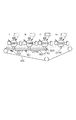
図7、及び図8は複数の感光ドラムを有するタンデム型の画像形成装置の概略図である。図7は、全ての感光ドラム209を中間転写ベルト230に当接させる画像形成時の状態(第一の状態)である。図8はブラック感光ドラム209Kのみを中間転写ベルト230に当接させるモノクロモード(ブラック単色の単色モード)の状態(第二の状態)である。なお、図1と同一部材については同じ符号を付してその詳細な説明は省略する。
<Details of primary transfer roller attachment / detachment operation>
7 and 8 are schematic views of a tandem image forming apparatus having a plurality of photosensitive drums. FIG. 7 shows a state (first state) at the time of image formation in which all the
一次転写ローラ離間動作(一転離間動作)について図7を用いて説明する。本実施例では、第一の状態と第二の状態とに切換えにより設定可能な当接離間機構を有する。当接離間機構は、一次転写ローラ保持フレーム502、偏心カム501、バネ500を有する構成である。図7から一次転写ローラ保持フレーム502が離間する方向に偏心カム501が回転されると、バネ500の付勢力によって一次転写ローラ保持フレーム502がカラー感光ドラム209Y、209M、209Cから離間する。そして、ブラック一次転写ローラ211Kのみがブラック感光ドラム209Kに当接した状態(図8)になる。その結果、中間転写ベルト230はブラック感光ドラムのみに当接した状態になる(カラードラム脱モノクロモード)。この一連の動作のことを一転離間動作と呼ぶ。
The primary transfer roller separation operation (one-turn separation operation) will be described with reference to FIG. 7. In this embodiment, the contact separation mechanism that can be set by switching between the first state and the second state is provided. The contact separation mechanism includes a primary transfer
一次転写ローラ当接動作(一転当接動作)について図8を用いて説明する。図8から一次転写ローラ保持フレーム502が離間する方向に偏心カム501が回転されると、バネ500の付勢力によって一次転写ローラ保持フレーム502がカラー感光ドラム209Y、209M、209Cから離間し、全ての一次転写ローラ211が感光ドラム209に当接した状態(図7)になる。その結果、中間転写ベルト230は全ての感光ドラム209に当接した状態になる。この一連の動作のことを一転当接動作と呼ぶ。
The primary transfer roller contact operation (one-turn contact operation) will be described with reference to FIG. When the
しかし、上述したように図8のようにモノクロモードにおいてはブラック感光ドラム209Kのみを中間転写ベルト230に当接させている状態である。そのため、中間転写ベルトにあまり負荷がかかっていない状態で回転しており、外部からの負荷に対して非常に弱い状態になっている。そのため、二次転写部231、232(図1)に厚紙等の所定厚さ以上の用紙が進入した場合や、用紙が所定速度以上の搬送速度で進入した場合には、中間転写ベルト230に速度変動が発生し易くなるためショックが生じやすくなる。ショック軽減のために、本実施例の画像形成装置は紙種によってカラー用の一次転写ローラを当接させてモノクロ画像を形成するモード(カラードラム着モノクロモード)がある。
However, as described above, in the monochrome mode as shown in FIG. 8, only the black
2.制御態様
図3は本実施例の画像形成装置10の主要部の制御態様を示すブロック図である。
2. Control mode FIG. 3 is a block diagram showing a control mode of a main part of the
画像形成装置10は画像形成装置10の各部の動作を統括制御するCPU回路部305を有する。CPU回路部305は画像形成装置10の制御処理を行う制御手段(実行部)としてのCPU306を有する。またCPU回路部305は、CPU306が動作するためのプログラムを格納しているROM307を有する。CPU306はROM307に格納されているプログラムにより各制御部302、303、304を総括的に制御する。またCPU回路部305は、CPU306が一時的にデータを記憶しておくために使用される記憶手段であるRAM308を有する。これらのCPU306とROM307とRAM308を包含したものがCPU回路部305となっている。
The
外部I/F301はコンピュータ300や操作表示部309から入力された画像形成ジョブを画像処理部303に送る。イメージリーダ制御部304は上述スキャナユニット202などに対する駆動制御を行う。
The external I /
画像処理部303は、CPU306からの制御信号に従って外部I/F301やイメージリーダ制御部304から送られてきた印刷ジョブを1部単位の画像データや1ページ単位の画像データに変換し、印刷制御部(画像形成を実行する実行部)に画像データを送る。また、受け付けた印刷ジョブをジョブ終了まで受け付け順番とともにRAM308に記憶する。
The
印刷制御部302はCPU306からの制御信号に従って印刷を行う各種負荷を制御する。図4は印刷制御部302の詳細を表す。搬送制御部401は用紙を供給、搬送するためのモータ、ローラ、クラッチ、ソレノイド、フラッパなどを駆動する。定着制御部402は定着部226を制御して用紙上にトナーを定着させる。センサ検知部403は画像形成装置に備え付けられているセンサの値を読み取る。画像形成制御部409はトナー補給装置制御部404、制御部405、現像制御部405、感光ドラム制御部406、露光制御部407、帯電制御部408、一次転写制御部410によってトナー像を現像、補給し中間転写ベルト230に転写する。二次転写制御部411によって中間転写ベルト230上のトナー像を用紙に転写する。一転着脱制御部412によって前述の一転離間動作、一転当接動作が各色の感光ドラム209ごとに行われる。
The
操作部309は操作表示装置40を制御する。操作表示部309は操作表示装置40によってなされた、ユーザからの各種入力を外部I/F301へ渡す制御を行う。また、操作表示部309はCPU回路部305の処理結果として操作表示装置40に表示してユーザへ通知する必要があるデータを外部I/F301から受け取って操作表示装置40に出力するように制御を行う。
The
図5は本実施例における実行フローチャートを示している。本実施例では、カラー用現像器212Y,M,C内のトナー濃度の検出値が予め定められた閾値以下の場合は、以下を選択する。カラー用トナーカートリッジが無く交換必要と判断したときは、カラードラム着モノクロモードでプリントする必要のある紙種であっても、カラードラム脱モノクロモードとしてプリントを行う。
FIG. 5 shows an execution flowchart in this embodiment. In this embodiment, when the detected value of the toner concentration in the
S001において、CPU306はトナー補給装置250に付属しているトナーセンサ17の検出値をセンサ検知部403から得る。その後ROM307に格納されているプログラムに基づいて、CPU306はブラックトナーで印刷が可能か否かを判断する。ブラックトナーが不足している場合、すなわちブラックトナー残量が印刷可能量に達していない場合はそのままプリントを終了する。ブラックトナーが印刷可能量に達していると判断された場合は、S002にてCPU306は印刷可能量にトナー残量が達していないカラーがあるか否かを判断する。カラートナー全ての残量が印刷可能量に達していると判断された場合は、S003においてCPU306はジョブの印刷データがモノクロかカラーかを判断する。印刷データがカラーであると判断された場合、CPU306はS009において一転当接制御を行う。カラーモードで印刷を行う場合は、感光ドラム209全てを中間転写ベルト230に当接させる必要があるためである。その後S010にてCPU306はフルカラーモードで印刷を行う。
In S001, the
S003においてジョブが連続したモノクロの画像形成ジョブであると判断された場合、S004においてCPU306は紙種判定を行う。上カセット215或いは下カセット216にセットされている紙種を操作表示装置40によってユーザが入力する。入力された紙種をCPU306が一転離間時にショックを引き起こす紙種かどうかを判断する。本実施例では、紙種判定を入力により行われたが、記録材の種類を検知するセンサの出力に基づく構成であっていい。本実施例では判断基準として紙の坪量が106gsm以上とした(以降106gsm以上の坪量の紙種を厚紙と表現し、それ以下の紙を普通紙と表現する)。本実施例では、坪量が所定値以上のときにはカラードラム着モノクロモードで単色の画像形成を行う。ショックが起きないと判断された場合はS005においてCPU306は前述の一転離間制御を行う。その後S006にてカラードラム脱モノクロモードでプリントする。カラードラム脱モノクロモード時はカラー現像装置212Y,M,Cの動作は停止している。S004でショックが起きると判断された場合は、S007においてCPU306は前述の一転当接制御を行いS008にてCPU306はカラードラム着モノクロモードで連続してプリントする。この場合もカラー現像装置212Y,M,Cは基本的には動作を停止するが、先に説明した通り予め定められたタイミングで作像動作を開始し、クリーニングブレードにトナーを供給するためのトナー帯を行う。トナー帯打ちの際の各種高圧や駆動の立ち上げ下やカラー現像装置212Y,M,C内の現像剤のトナー濃度の検出と補給に関してはフルカラープリント時と同様に行う。本実施例においては、カラー各色ともA4換算100枚プリントに1回という所定の間隔で主走査幅323mm、副走査幅65mmのベタ濃度の帯を形成した。
When it is determined in S003 that the job is a continuous monochrome image forming job, the
S002においてトナー残量が印刷可能量に達していないカラーが一つでもあると判断された場合、S011でCPU306はジョブがモノクロまたはカラーであるかを判断する。ジョブがカラーであったと判断された場合はプリントを終了する。ジョブがモノクロだった場合は、CPU306はS012においてS004と同じ判断を行う。普通紙と判断された場合は、CPU306はS013においてS005と同じ一転離間制御を行う。CPU306はS014においてS006と同じカラードラム脱モノクロプリントを実行する。S012において厚紙であると判断された場合、CPU306はS015においてカラー現像装置212Y,M,Cに設置しているトナー濃度検知部であるインダクタンスセンサ252Y,M,Cからの反応をセンサ検知部403から得る。その後ROM307に格納されているプログラムに基づいて、CPU306は予め定められた一転離間トナー濃度閾値と、センサ検知部403から得たインダクタンスセンサ252の検出トナー濃度値(つまり現像装置内のトナー濃度値)を比較する。トナー濃度に換算して「一転離間トナー濃度閾値<現像装置内のトナー濃度値」であれば、S017,S018においてS007,S008と同様のカラードラム着モノクロプリントを行う。本実施例においては、一転離間トナー濃度閾値を4.0%とした。一方、S015でジョブの実行中に「一転離間トナー濃度閾値≧現像装置内のトナー濃度値」となった場合は、CPU306はS016においてプリントを続行するか否かをユーザに判断を仰ぐために警告を出す。図9のようにしてROM307に格納されている「カラートナーが不足しています。印刷を続行しますか。」という文字列をポップウィンドウとして操作表示装置40に出力する。ユーザがNOボタン622をタッチした場合、すなわちプリントを中断し、トナーが補給されることを待機状態する。このように、本実施例では、トナーが補給されることを待機状態を選択可能となっている。
If it is determined in S002 that there is at least one color in which the remaining amount of toner does not reach the printable amount, the
ユーザがYESボタン623をタッチした場合、すなわち印刷を続行する場合は、S013,S014においてカラードラム脱モノクロプリントを実行可能となっている。
When the user touches the
最後にS019において、当該プリントジョブ中に次にプリントすべきページがあるか判断し、ある場合は次ページのプリントにおいてS001からのフローを再度実行し、無い場合はそのままプリントを終了する。本実施例ではプリントジョブ中にボトルを補充しても当該プリントジョブ中にカラードラム着モノクロプリントには戻さないとしているが、これに限定する必要はなく、カラー現像装置のトナー濃度で一転の当接離間を判断してモノクロプリントを行えばよい。 Finally, in S019, it is determined whether there is a page to be printed next in the print job, and if there is, the flow from S001 is executed again in the print of the next page, and if not, the print is terminated as it is. In this embodiment, even if the bottle is replenished during the print job, it is not returned to the color drum wearing monochrome print during the print job, but it is not necessary to limit this, and the toner concentration of the color developing apparatus changes. Monochrome printing may be performed by judging the contact and separation.
本実施例では、S016においてプリントジョブの続行か停止かの判断を仰ぐための警告を表示した。しかし、図11に示したフローチャートのようにショックの出ない画像品位が保証されるカラードラム着モノクロモードプリントを継続するか否かの判断を仰ぐ警告を表示してもよい。また、S016の判断を省略しS015でYESとなり次第直ちにカラードラム脱モノクロモードでプリントを行ってもよい。 In this embodiment, a warning is displayed in S016 to ask for a judgment as to whether to continue or stop the print job. However, as shown in the flowchart shown in FIG. 11, a warning may be displayed asking for a judgment as to whether or not to continue the color drum wearing monochrome mode printing that guarantees the image quality without shock. Further, the determination of S016 may be omitted and printing may be performed in the color drum demonochrome mode as soon as YES is obtained in S015.
また本実施例ではS002とS015の判断をカラー用トナーカートリッジの内どれか一つでも不足と判断し、S015の判断でカラー現像装置212Y,M,Cの内どれか一つでもYESとなった場合とした。しかし、これに限定される必要はなく色毎に上記判断を行ってもよい。
Further, in this embodiment, it was determined that any one of the color toner cartridges was insufficient in the judgments of S002 and S015, and the judgment of S015 was YES in any one of the
本発明の別の実施例を示す。実質的に同一若しくは相当する機能、構成を有する要素には同一符号を付して詳細な説明は省略し、本実施例特有の構成部分のみ詳細に説明する。実施例1では、カラー用トナーカートリッジが無い場合、カラードラム着モノクロモードでプリントする必要のある紙種であっても、カラー用現像器内のトナー濃度の検出値によってカラードラム脱モノクロモードでプリントするものであった。本実施例では、カラー用トナーカートリッジが無い場合におけるカラードラム着モノクロモード時であっても、カラー用現像器内のトナー濃度の検出値が予め定められた閾値以下でかつ、残された画像形成数がある閾値(所定値)以上の場合にのみカラードラム脱モノクロモードをプリントすることが特徴的である。 Another embodiment of the present invention is shown. Elements having substantially the same or equivalent functions and configurations are designated by the same reference numerals, detailed description thereof will be omitted, and only the components specific to this embodiment will be described in detail. In the first embodiment, when there is no color toner cartridge, even if the paper type needs to be printed in the color drum wearing monochrome mode, it is printed in the color drum demonochrome mode according to the detected value of the toner density in the color developer. It was something to do. In this embodiment, even in the color drum wearing monochrome mode when there is no color toner cartridge, the detected value of the toner concentration in the color developer is equal to or less than a predetermined threshold value, and the remaining image is formed. It is characteristic that the color drum demonochrome mode is printed only when the number is equal to or more than a certain threshold (predetermined value).
カラー用トナーカートリッジが無い場合におけるカラードラム着モノクロモードで連続して画像形成するジョブの実行中に、「一転離間トナー濃度閾値≧現像装置内のトナー濃度値」となった場合でも(即ち図5のS015でYESの場合)、数枚のプリントであれば画像形成ユニットへの影響は小さい。
上記場合でも直ちにユーザへの警告を出す(あるいはカラードラム脱モノクロモードへと移行させる)のではなく、残されたプリントジョブが予め定められた閾値(所定値)を上回った時はカラードラム脱モノクロモードにする。所定値より小さければ残されたプリントを実行することでユーザストレスを更に軽減することが可能となる。
Even when "one-turn separation toner density threshold ≥ toner density value in the developing device" is satisfied during execution of a job for continuously forming an image in the color drum wearing monochrome mode when there is no color toner cartridge (that is, FIG. 5). (If YES in S015), the effect on the image forming unit is small if there are several prints.
Even in the above case, instead of immediately issuing a warning to the user (or shifting to the color drum demonochrome mode), when the remaining print job exceeds a predetermined threshold value (predetermined value), the color drum demonochrome is removed. Set to mode. If it is smaller than the predetermined value, the user stress can be further reduced by executing the remaining print.
図10は本実施例の実行フローチャートである。実施例1のフローチャートのS016の代わりにS020、S021、S022、S023、S024が追加されている。S015で「一転離間トナー濃度閾値≧現像装置内のトナー濃度値」となった場合、実施例1の場合ユーザへの警告を出すかあるいは直ちにカラードラム脱モノクロモードへと移行させた。本実例ではS020でRAM308に記憶されている印刷データから当該ジョブの残りプリント枚数をCPU306が算出し、予め定められたプリント閾値と比較する。「残りプリント枚数≧プリント閾値」であれば、S013、S014において実施例1の場合と同様カラードラム脱モノクロプリントを行う。「残りプリント枚数<プリント閾値」であれば、残りプリント枚数(画像形成数)が少ないためユーザビリティを優先させS023にて停止フラグをONにした後、S017、S018にてこのままカラードラム着モノクロプリントを行う。本実施例においては、プリント閾値を10枚に設定した。以降当該ジョブが終了するまでS001からS019までの一連のフローを実行する。停止フラグはカラートナーカートリッジを新しく交換したタイミングでOFFとした。
FIG. 10 is an execution flowchart of this embodiment. S020, S021, S022, S023, and S024 are added in place of S016 in the flowchart of the first embodiment. When "one-turn separation toner concentration threshold value ≥ toner concentration value in the developing device" is satisfied in S015, in the case of Example 1, a warning to the user is issued or the mode is immediately shifted to the color drum demonochrome mode. In this example, the
S020で「NO」となってからは当該ジョブ中であれば残りプリント枚数は単調に減少するだけなので常にS020は「NO」となり続ける。一方、当該ジョブが終了して新しいジョブをプリント開始する場合は、S022にて停止フラグを確認する。S023、S024で当該ジョブのフルカラー/モノクロと紙種を確認する。停止フラグがONかつモノクロかつ厚紙プリントの時のみプリントは無条件にS013、S014にてカラードラム脱モノクロプリントを行う。それ以外の場合はS001から同様のフローとなる。このようにすることで、一旦停止フラグをONにした状態の装置において、カラートナーカートリッジが交換されずに、プリント閾値以下の短いプリント枚数の厚紙モノクロジョブが継続して実行されることによる、画像形成ユニットへの影響を小さくしている。 After becoming "NO" in S020, the number of remaining prints only monotonously decreases during the job, so S020 always keeps becoming "NO". On the other hand, when the job ends and a new job starts printing, the stop flag is confirmed in S022. Check the full color / monochrome and paper type of the job in S023 and S024. Only when the stop flag is ON, monochrome, and thick paper printing, color drum demonochrome printing is performed unconditionally in S013 and S014. In other cases, the flow is the same from S001. By doing so, in the device in which the stop flag is temporarily turned on, the thick paper monochrome job with a short number of prints below the print threshold is continuously executed without replacing the color toner cartridge. The effect on the forming unit is reduced.
なお、上記実施例では、現像装置内のトナー濃度でトナーの残量を判別する構成であった。その他の構成として、例えば、トナー供給装置のトナー貯蔵部内のトナー量を検知するトナー量検知センサが所定量よりも小さくなった場合に、上記制御を行ってもよい。この場合であっても、現像装置内のトナー量が所定量を下回る場合がなるからである。 In the above embodiment, the remaining amount of toner is determined based on the toner concentration in the developing device. As another configuration, for example, the above control may be performed when the toner amount detection sensor that detects the toner amount in the toner storage portion of the toner supply device becomes smaller than a predetermined amount. Even in this case, the amount of toner in the developing device may be less than the predetermined amount.
なお、上記実施例では、2成分の現像剤について説明したが、一成分の現像剤であっても同様の効果を得られる。 In the above embodiment, the two-component developer has been described, but the same effect can be obtained even with a one-component developer.
Claims (5)
中間転写部材と、
第1の像担持体と、前記第1の像担持体に形成された静電潜像を色トナーを用いて現像する第1の現像装置と、前記中間転写部材にトナー画像を転写後に前記第1の像担持体に残留した色トナーを除去する第1のクリーニングブレードと、を含む第1の画像形成部と、
第2の像担持体と、前記第2の像担持体に形成された静電潜像を黒トナーを用いて現像する第2の現像装置と、前記中間転写部材にトナー画像を転写後に前記第2の像担持体に残留した黒トナーを除去する第2のクリーニングブレードと、を含む第2の画像形成部と、
前記第1の像担持体が前記中間転写部材に接触し且つ前記第2の像担持体が前記中間転写部材に接触している第1の状態と、前記第1の像担持体が前記中間転写部材から離間し且つ前記第2の像担持体が前記中間転写部材に接触している第2の状態との間で切り替え可能な当接離間機構と、
黒単色で記録材に画像を形成する際、前記第1の状態において前記第1の現像装置が前記第1のクリーニングブレードに供給するためのトナー画像を形成し且つ前記第2の画像形成部が当該記録材に転写されるトナー画像を形成する第1の黒単色モードと、前記第2の状態において前記第2の画像形成部が当該記録材に転写されるトナー画像を形成する第2の黒単色モードと、を含む複数のモードの中から1つのモードを選択して画像形成を実行可能な実行部と、
前記第1の現像装置内のトナー量に関する情報を検知する検知部と、
操作部と、
を備え、
前記実行部は、
前記第1の黒単色モードで画像形成を実行している間に、前記検知部により検知された前記情報が前記第1の現像装置内のトナー量が所定量よりも少ないことを示す場合には、画像形成を中断し、且つ前記第1の黒単色モードから前記第2の黒単色モードに切り替えて画像形成を再開させる指示を受け付けるための画面を前記操作部に表示させ、
前記操作部を介して前記指示を受け付けた場合には、前記第1の黒単色モードから前記第2の黒単色モードに切り替えて画像形成を再開し、
前記操作部を介して前記指示を受け付けなかった場合には、前記第1の現像装置内のトナー量が前記所定量に達するまで画像形成の中断を継続し、前記第1の現像装置にトナーが供給されて前記第1の現像装置内のトナー量が前記所定量に達したら前記第1の黒単色モードで画像形成を再開する
ことを特徴とする画像形成装置。 An image forming device that forms an image on a recording material.
With the intermediate transfer member,
The first image carrier, the first developing device that develops the electrostatic latent image formed on the first image carrier using color toner, and the first after transferring the toner image to the intermediate transfer member. A first image forming portion including a first cleaning blade for removing color toner remaining on the image carrier of No. 1 and a first image forming portion.
A second image carrier, a second developing device that develops an electrostatic latent image formed on the second image carrier using black toner, and the first after transferring the toner image to the intermediate transfer member. A second image forming portion including a second cleaning blade for removing black toner remaining on the image carrier of No. 2 and a second image forming portion.
The first state in which the first image carrier is in contact with the intermediate transfer member and the second image carrier is in contact with the intermediate transfer member, and the first image carrier is in contact with the intermediate transfer member. A contact separation mechanism that is separated from the member and can be switched between a second state in which the second image carrier is in contact with the intermediate transfer member.
When forming an image on the recording material in a single black color, the first developing apparatus forms a toner image to be supplied to the first cleaning blade in the first state, and the second image forming unit forms a toner image. A first black monochromatic mode that forms a toner image transferred to the recording material, and a second black that the second image forming unit forms a toner image that is transferred to the recording material in the second state. An execution unit that can execute image formation by selecting one mode from a plurality of modes including a single color mode and
A detector that detects information about the amount of toner in the first developing device, and
Operation unit and
With
The execution unit
When the information detected by the detection unit indicates that the amount of toner in the first developing apparatus is less than a predetermined amount while the image formation is being executed in the first black monochromatic mode. , interrupting the image forming, and prior Symbol to display a screen for receiving an instruction to resume the images formed by switching to the second black monochrome mode from the first black monochrome mode to the operating unit,
When the instruction is received via the operation unit, the image formation is restarted by switching from the first black monochromatic mode to the second black monochromatic mode.
When the instruction is not received via the operation unit, the image formation is continuously interrupted until the amount of toner in the first developing device reaches the predetermined amount, and the toner is transferred to the first developing device. When the amount of toner supplied and the amount of toner in the first developing apparatus reaches the predetermined amount, image formation is restarted in the first black monochromatic mode.
An image forming apparatus comprising and this.
ことを特徴とする請求項1に記載の画像形成装置。 The first developing device, the while running the images form formed at the first black monochrome mode, the first predetermined interval of toner images of a predetermined length with respect to the rotational direction of the image bearing member The image forming apparatus according to claim 1 , wherein the image forming apparatus is formed for each.
ことを特徴とする請求項1又は2に記載の画像形成装置。 When an image is formed on a recording material in a single black color, the execution unit indicates that the information detected by the detection unit indicates that the amount of toner in the first developing apparatus is larger than the predetermined amount, and the information is said. If the basis weight of the recording material is larger than a predetermined value, the running image type forming a first black monochrome mode, if the basis weight of the recording material is smaller than the predetermined value, the second the image forming apparatus according to claim 1 or 2, characterized in that performing the image type forming a black monochromatic mode.
第4の像担持体と、前記第4の像担持体に形成された静電潜像を色トナーを用いて現像する第4の現像装置と、前記中間転写部材にトナー画像を転写後に前記第4の像担持体に残留した色トナーを除去する第4のクリーニングブレードと、を含み、前記中間転写部材にトナー画像を形成する第4の画像形成部と、
を更に備え、
前記第1の状態は、前記第1の像担持体が前記中間転写部材に接触し、前記第2の像担持体が前記中間転写部材に接触し、前記第3の像担持体が前記中間転写部材に接触し、且つ前記第4の像担持体が前記中間転写部材に接触している状態であり、
前記第2の状態は、前記第1の像担持体が前記中間転写部材から離間し、前記第2の像担持体が前記中間転写部材から接触し、前記第3の像担持体が前記中間転写部材から離間し、且つ前記第4の像担持体が前記中間転写部材から離間している状態であり、
前記実行部は、
前記第1の黒単色モードで画像形成を実行している間に、前記第1の現像装置内のトナー量、前記第3の現像装置内のトナー量、前記第4の現像装置内のトナー量のいずれかのトナー量が前記所定量よりも少ない場合には、画像形成を中断し、且つ前記指示を受け付けるための画面を前記操作部に表示させ、
前記操作部を介して前記指示を受け付けた場合には、前記第1の黒単色モードから前記第2の黒単色モードに切り替えて画像形成を再開し、
前記操作部を介して前記指示を受け付けなかった場合には、前記第1の現像装置内のトナー量、前記第3の現像装置内のトナー量、前記第4の現像装置内のトナー量のうち前記所定量よりも少なくなった現像装置内のトナー量が前記所定量に達するまで画像形成の中断を継続し、前記第1の現像装置内のトナー量、前記第3の現像装置内のトナー量、前記第4の現像装置内のトナー量のうち前記所定量よりも少なくなった現像装置にトナーが供給されて当該現像装置内のトナー量が前記所定量に達したら前記第1の黒単色モードで画像形成を再開する
ことを特徴とする請求項1乃至3のいずれか1項に記載の画像形成装置。 A third image-bearing body, a third developing device that develops an electrostatic latent image formed on the third image-bearing body with colored toner, and the third developing device after transferring the toner image to the intermediate transfer member. A third image forming portion that includes a third cleaning blade that removes color toner remaining on the image carrier of No. 3 and forms a toner image on the intermediate transfer member.
A fourth image-bearing body, a fourth developing device that develops an electrostatic latent image formed on the fourth image-bearing body with colored toner, and the first after transferring the toner image to the intermediate transfer member. A fourth image forming portion that includes a fourth cleaning blade that removes color toner remaining on the image carrier of No. 4 and forms a toner image on the intermediate transfer member.
Further prepare
In the first state, the first image carrier is in contact with the intermediate transfer member, the second image carrier is in contact with the intermediate transfer member, and the third image carrier is in contact with the intermediate transfer member. A state in which the fourth image carrier is in contact with the member and the intermediate transfer member is in contact with the intermediate transfer member.
In the second state, the first image carrier is separated from the intermediate transfer member, the second image carrier is in contact with the intermediate transfer member, and the third image carrier is the intermediate transfer member. A state in which the fourth image carrier is separated from the member and is separated from the intermediate transfer member.
The execution unit,
While performing the image type forming before Symbol first black monochrome mode, the toner amount of the first in the developing device, the toner amount of the third in the developing device, the fourth in the developing device wherein the one Kano toner amount of the toner amount in the small yet if than the predetermined amount, to interrupt the image formation, causes and display the screen for receiving said instruction to the operation unit,
When the instruction is received via the operation unit, the image formation is restarted by switching from the first black monochromatic mode to the second black monochromatic mode.
When the instruction is not received via the operation unit, of the toner amount in the first developing device, the toner amount in the third developing device, and the toner amount in the fourth developing device. The image formation is interrupted until the amount of toner in the developing apparatus becomes smaller than the predetermined amount reaches the predetermined amount, and the amount of toner in the first developing apparatus and the amount of toner in the third developing apparatus are continued. When the toner is supplied to the developing device in which the amount of toner in the fourth developing device is less than the predetermined amount and the amount of toner in the developing device reaches the predetermined amount, the first black monochromatic mode is used. The image forming apparatus according to any one of claims 1 to 3 , wherein the image forming is restarted at the same time.
ことを特徴とする請求項1乃至4のいずれか1項に記載の画像形成装置。 The execution unit, when the toner amount in said the information detected by the detection unit of the first developing device indicates that less than said predetermined amount, said screen for notifying the information on the feeding toner supply The image forming apparatus according to any one of claims 1 to 4 , wherein the image forming apparatus is displayed on an operation unit.
Priority Applications (5)
| Application Number | Priority Date | Filing Date | Title |
|---|---|---|---|
| JP2017037733A JP6921558B2 (en) | 2017-02-28 | 2017-02-28 | Image forming device |
| GB1802471.1A GB2561442B (en) | 2017-02-28 | 2018-02-15 | Image forming apparatus |
| US15/899,762 US10401752B2 (en) | 2017-02-28 | 2018-02-20 | Image forming apparatus |
| DE102018104432.1A DE102018104432A1 (en) | 2017-02-28 | 2018-02-27 | Image forming apparatus |
| CN201810164249.4A CN108508722A (en) | 2017-02-28 | 2018-02-28 | Image forming apparatus |
Applications Claiming Priority (1)
| Application Number | Priority Date | Filing Date | Title |
|---|---|---|---|
| JP2017037733A JP6921558B2 (en) | 2017-02-28 | 2017-02-28 | Image forming device |
Publications (3)
| Publication Number | Publication Date |
|---|---|
| JP2018141940A JP2018141940A (en) | 2018-09-13 |
| JP2018141940A5 JP2018141940A5 (en) | 2020-04-09 |
| JP6921558B2 true JP6921558B2 (en) | 2021-08-18 |
Family
ID=61783649
Family Applications (1)
| Application Number | Title | Priority Date | Filing Date |
|---|---|---|---|
| JP2017037733A Active JP6921558B2 (en) | 2017-02-28 | 2017-02-28 | Image forming device |
Country Status (5)
| Country | Link |
|---|---|
| US (1) | US10401752B2 (en) |
| JP (1) | JP6921558B2 (en) |
| CN (1) | CN108508722A (en) |
| DE (1) | DE102018104432A1 (en) |
| GB (1) | GB2561442B (en) |
Families Citing this family (3)
| Publication number | Priority date | Publication date | Assignee | Title |
|---|---|---|---|---|
| CN111546795B (en) * | 2019-02-12 | 2022-05-13 | 珠海艾派克微电子有限公司 | Printing control method, consumable chip and image forming system |
| DE102021000558A1 (en) | 2021-01-23 | 2022-07-28 | Heinrich Hora | Non-thermal laser nuclear fusion ignition of hydrogen and boron11 |
| JP2023172295A (en) * | 2022-05-23 | 2023-12-06 | キヤノン株式会社 | Image forming apparatus |
Family Cites Families (26)
| Publication number | Priority date | Publication date | Assignee | Title |
|---|---|---|---|---|
| US6771924B2 (en) * | 2001-09-04 | 2004-08-03 | Canon Kabushiki Kaisha | Image forming apparatus having different modes for preventing defective cleaning |
| JP3953360B2 (en) * | 2002-04-24 | 2007-08-08 | シャープ株式会社 | Color image forming apparatus |
| JP4455197B2 (en) * | 2003-07-31 | 2010-04-21 | キヤノン株式会社 | Image forming apparatus |
| JP2005222035A (en) * | 2004-01-09 | 2005-08-18 | Canon Inc | Electrophotographic image forming apparatus |
| KR100565090B1 (en) * | 2004-10-28 | 2006-03-30 | 삼성전자주식회사 | Monochromatic image printing method of single pass color printer |
| JP4701900B2 (en) * | 2005-07-27 | 2011-06-15 | 富士ゼロックス株式会社 | Image forming apparatus |
| JP2007212936A (en) * | 2006-02-13 | 2007-08-23 | Fuji Xerox Co Ltd | Image forming apparatus |
| JP4215091B2 (en) * | 2006-10-23 | 2009-01-28 | セイコーエプソン株式会社 | Image forming apparatus and image forming method |
| JP2008191514A (en) * | 2007-02-06 | 2008-08-21 | Canon Inc | Image forming apparatus |
| JP4962196B2 (en) * | 2007-08-06 | 2012-06-27 | 富士ゼロックス株式会社 | Image forming apparatus |
| JP5223468B2 (en) * | 2008-06-03 | 2013-06-26 | 株式会社リコー | Image forming apparatus |
| JP2010066416A (en) | 2008-09-09 | 2010-03-25 | Canon Inc | Image forming apparatus |
| JP5402438B2 (en) * | 2009-09-14 | 2014-01-29 | 株式会社リコー | Image forming apparatus and control method thereof |
| JP5822460B2 (en) | 2009-12-21 | 2015-11-24 | キヤノン株式会社 | Image forming apparatus |
| JP2012237977A (en) * | 2011-04-27 | 2012-12-06 | Canon Inc | Image forming apparatus |
| JP5839878B2 (en) * | 2011-07-29 | 2016-01-06 | キヤノン株式会社 | Image forming apparatus |
| JP5862425B2 (en) * | 2012-04-01 | 2016-02-16 | コニカミノルタ株式会社 | Image forming apparatus |
| JP6210693B2 (en) * | 2013-02-21 | 2017-10-11 | キヤノン株式会社 | Image forming apparatus |
| JP2014170099A (en) * | 2013-03-04 | 2014-09-18 | Toshiba Corp | Image forming apparatus and image forming method |
| JP2014174193A (en) * | 2013-03-06 | 2014-09-22 | Toshiba Corp | Image forming apparatus and image forming method |
| JP2015022189A (en) * | 2013-07-19 | 2015-02-02 | キヤノン株式会社 | Image forming apparatus |
| JP6296895B2 (en) | 2014-05-20 | 2018-03-20 | キヤノン株式会社 | Image forming apparatus |
| JP2016114859A (en) | 2014-12-17 | 2016-06-23 | キヤノン株式会社 | Image forming apparatus |
| JP6669378B2 (en) * | 2015-03-12 | 2020-03-18 | キヤノン株式会社 | Image forming device |
| JP2017142305A (en) | 2016-02-08 | 2017-08-17 | キヤノン株式会社 | Image forming apparatus |
| JP2018054653A (en) * | 2016-09-26 | 2018-04-05 | キヤノン株式会社 | Image formation device |
-
2017
- 2017-02-28 JP JP2017037733A patent/JP6921558B2/en active Active
-
2018
- 2018-02-15 GB GB1802471.1A patent/GB2561442B/en not_active Expired - Fee Related
- 2018-02-20 US US15/899,762 patent/US10401752B2/en active Active
- 2018-02-27 DE DE102018104432.1A patent/DE102018104432A1/en not_active Withdrawn
- 2018-02-28 CN CN201810164249.4A patent/CN108508722A/en active Pending
Also Published As
| Publication number | Publication date |
|---|---|
| US20180246437A1 (en) | 2018-08-30 |
| DE102018104432A1 (en) | 2018-08-30 |
| GB2561442B (en) | 2020-02-12 |
| JP2018141940A (en) | 2018-09-13 |
| GB2561442A (en) | 2018-10-17 |
| US10401752B2 (en) | 2019-09-03 |
| GB201802471D0 (en) | 2018-04-04 |
| CN108508722A (en) | 2018-09-07 |
Similar Documents
| Publication | Publication Date | Title |
|---|---|---|
| KR101607469B1 (en) | Printing apparatus capable of preventing sheet feed error in cleaning, method of controlling the printing apparatus, and storage medium | |
| JP4548477B2 (en) | Image forming apparatus | |
| JP2006293240A (en) | Image forming apparatus | |
| US9921542B2 (en) | Image forming apparatus for forming image using developer, method for regulating attachment/detachment of developer storage portion | |
| JP6921558B2 (en) | Image forming device | |
| US10845748B2 (en) | Image forming apparatus and control method to check consumable part consumption | |
| JP4424357B2 (en) | Image forming apparatus, image forming method, and image forming program | |
| JP2010145864A (en) | Image forming apparatus | |
| JP2006235009A (en) | Color image forming apparatus | |
| JP4563783B2 (en) | Image forming apparatus and waste toner bottle | |
| JP2005255386A (en) | Image forming device | |
| JP2018054653A (en) | Image formation device | |
| JP6514652B2 (en) | Image forming device | |
| JP2006142713A (en) | Image formation device, refilling paper display method, and program for allowing computer to execute the method | |
| JP2019207365A (en) | Image forming apparatus | |
| JP7379077B2 (en) | Image forming device, method of controlling the image forming device, and computer program | |
| US20230341802A1 (en) | Image forming apparatus | |
| JP2008107650A (en) | Image forming apparatus, control method for image forming apparatus and control program for image forming apparatus | |
| JP7196441B2 (en) | image forming device | |
| KR101279070B1 (en) | Method of printing images continuously even when toner is completely consumed | |
| JP2010243710A (en) | Image processor and image processing method | |
| JP2010091802A (en) | Image forming apparatus | |
| JP2008134461A (en) | Image forming apparatus, image forming method, image forming program, and recording medium | |
| JP2008216804A (en) | Image forming apparatus | |
| JP2008197189A (en) | Image forming apparatus |
Legal Events
| Date | Code | Title | Description |
|---|---|---|---|
| A521 | Request for written amendment filed |
Free format text: JAPANESE INTERMEDIATE CODE: A523 Effective date: 20200221 |
|
| A621 | Written request for application examination |
Free format text: JAPANESE INTERMEDIATE CODE: A621 Effective date: 20200221 |
|
| A977 | Report on retrieval |
Free format text: JAPANESE INTERMEDIATE CODE: A971007 Effective date: 20201223 |
|
| A131 | Notification of reasons for refusal |
Free format text: JAPANESE INTERMEDIATE CODE: A131 Effective date: 20210119 |
|
| A521 | Request for written amendment filed |
Free format text: JAPANESE INTERMEDIATE CODE: A523 Effective date: 20210226 |
|
| TRDD | Decision of grant or rejection written | ||
| A01 | Written decision to grant a patent or to grant a registration (utility model) |
Free format text: JAPANESE INTERMEDIATE CODE: A01 Effective date: 20210629 |
|
| A61 | First payment of annual fees (during grant procedure) |
Free format text: JAPANESE INTERMEDIATE CODE: A61 Effective date: 20210728 |
|
| R151 | Written notification of patent or utility model registration |
Ref document number: 6921558 Country of ref document: JP Free format text: JAPANESE INTERMEDIATE CODE: R151 |