JP5854705B2 - Beverage cartridge - Google Patents
Beverage cartridge Download PDFInfo
- Publication number
- JP5854705B2 JP5854705B2 JP2011184445A JP2011184445A JP5854705B2 JP 5854705 B2 JP5854705 B2 JP 5854705B2 JP 2011184445 A JP2011184445 A JP 2011184445A JP 2011184445 A JP2011184445 A JP 2011184445A JP 5854705 B2 JP5854705 B2 JP 5854705B2
- Authority
- JP
- Japan
- Prior art keywords
- lid
- cartridge
- beverage
- container
- filter
- Prior art date
- Legal status (The legal status is an assumption and is not a legal conclusion. Google has not performed a legal analysis and makes no representation as to the accuracy of the status listed.)
- Active
Links
- 235000013361 beverage Nutrition 0.000 title claims description 321
- 239000007788 liquid Substances 0.000 claims description 118
- 239000000463 material Substances 0.000 claims description 50
- 238000004519 manufacturing process Methods 0.000 claims description 41
- 230000002093 peripheral effect Effects 0.000 claims description 37
- 238000000034 method Methods 0.000 description 35
- 235000013353 coffee beverage Nutrition 0.000 description 26
- 235000016213 coffee Nutrition 0.000 description 23
- XLYOFNOQVPJJNP-UHFFFAOYSA-N water Substances O XLYOFNOQVPJJNP-UHFFFAOYSA-N 0.000 description 22
- 239000012530 fluid Substances 0.000 description 18
- 238000000605 extraction Methods 0.000 description 15
- 241001122767 Theaceae Species 0.000 description 13
- 239000011888 foil Substances 0.000 description 13
- 235000013616 tea Nutrition 0.000 description 13
- 229920000642 polymer Polymers 0.000 description 10
- 230000006870 function Effects 0.000 description 9
- 239000004033 plastic Substances 0.000 description 8
- 229920003023 plastic Polymers 0.000 description 8
- 229910052751 metal Inorganic materials 0.000 description 6
- -1 polypropylene Polymers 0.000 description 6
- 235000003599 food sweetener Nutrition 0.000 description 5
- 230000003993 interaction Effects 0.000 description 5
- 230000007246 mechanism Effects 0.000 description 5
- 239000002184 metal Substances 0.000 description 5
- 239000000126 substance Substances 0.000 description 5
- 239000003765 sweetening agent Substances 0.000 description 5
- 238000010586 diagram Methods 0.000 description 4
- 235000011869 dried fruits Nutrition 0.000 description 4
- 239000002245 particle Substances 0.000 description 4
- 238000000926 separation method Methods 0.000 description 4
- 238000003466 welding Methods 0.000 description 4
- 239000004743 Polypropylene Substances 0.000 description 3
- QVGXLLKOCUKJST-UHFFFAOYSA-N atomic oxygen Chemical compound [O] QVGXLLKOCUKJST-UHFFFAOYSA-N 0.000 description 3
- 230000008901 benefit Effects 0.000 description 3
- 238000009264 composting Methods 0.000 description 3
- 235000008504 concentrate Nutrition 0.000 description 3
- 239000007789 gas Substances 0.000 description 3
- 239000004615 ingredient Substances 0.000 description 3
- 230000001788 irregular Effects 0.000 description 3
- 239000000203 mixture Substances 0.000 description 3
- 238000012986 modification Methods 0.000 description 3
- 230000004048 modification Effects 0.000 description 3
- 239000001301 oxygen Substances 0.000 description 3
- 229910052760 oxygen Inorganic materials 0.000 description 3
- 230000035699 permeability Effects 0.000 description 3
- 229920001155 polypropylene Polymers 0.000 description 3
- 230000008569 process Effects 0.000 description 3
- 238000004064 recycling Methods 0.000 description 3
- 238000003860 storage Methods 0.000 description 3
- 238000009736 wetting Methods 0.000 description 3
- 229920000219 Ethylene vinyl alcohol Polymers 0.000 description 2
- 239000004793 Polystyrene Substances 0.000 description 2
- 239000000853 adhesive Substances 0.000 description 2
- 230000001070 adhesive effect Effects 0.000 description 2
- 230000004888 barrier function Effects 0.000 description 2
- 230000008859 change Effects 0.000 description 2
- 239000012141 concentrate Substances 0.000 description 2
- 239000012611 container material Substances 0.000 description 2
- 238000005553 drilling Methods 0.000 description 2
- UFRKOOWSQGXVKV-UHFFFAOYSA-N ethene;ethenol Chemical compound C=C.OC=C UFRKOOWSQGXVKV-UHFFFAOYSA-N 0.000 description 2
- 239000004715 ethylene vinyl alcohol Substances 0.000 description 2
- 235000020278 hot chocolate Nutrition 0.000 description 2
- 230000006872 improvement Effects 0.000 description 2
- 229920002223 polystyrene Polymers 0.000 description 2
- 238000002360 preparation method Methods 0.000 description 2
- 238000010926 purge Methods 0.000 description 2
- 239000002562 thickening agent Substances 0.000 description 2
- 241000272525 Anas platyrhynchos Species 0.000 description 1
- 241000196324 Embryophyta Species 0.000 description 1
- AFCARXCZXQIEQB-UHFFFAOYSA-N N-[3-oxo-3-(2,4,6,7-tetrahydrotriazolo[4,5-c]pyridin-5-yl)propyl]-2-[[3-(trifluoromethoxy)phenyl]methylamino]pyrimidine-5-carboxamide Chemical compound O=C(CCNC(=O)C=1C=NC(=NC=1)NCC1=CC(=CC=C1)OC(F)(F)F)N1CC2=C(CC1)NN=N2 AFCARXCZXQIEQB-UHFFFAOYSA-N 0.000 description 1
- 239000004698 Polyethylene Substances 0.000 description 1
- 241000533293 Sesbania emerus Species 0.000 description 1
- 230000004075 alteration Effects 0.000 description 1
- 229920001222 biopolymer Polymers 0.000 description 1
- 235000015115 caffè latte Nutrition 0.000 description 1
- 235000015116 cappuccino Nutrition 0.000 description 1
- 229920002678 cellulose Polymers 0.000 description 1
- 239000001913 cellulose Substances 0.000 description 1
- 235000020965 cold beverage Nutrition 0.000 description 1
- 238000004891 communication Methods 0.000 description 1
- 239000002361 compost Substances 0.000 description 1
- 238000011109 contamination Methods 0.000 description 1
- 238000007796 conventional method Methods 0.000 description 1
- 230000008878 coupling Effects 0.000 description 1
- 238000010168 coupling process Methods 0.000 description 1
- 238000005859 coupling reaction Methods 0.000 description 1
- 238000002788 crimping Methods 0.000 description 1
- YSXLJTGZMRNQSG-UHFFFAOYSA-L disodium;6-amino-5-[[2-[4-[2-[4-[2-[(2-amino-5-sulfonatonaphthalen-1-yl)diazenyl]phenyl]sulfonyloxyphenyl]propan-2-yl]phenoxy]sulfonylphenyl]diazenyl]naphthalene-1-sulfonate Chemical compound [Na+].[Na+].C1=CC=C2C(N=NC3=CC=CC=C3S(=O)(=O)OC3=CC=C(C=C3)C(C)(C=3C=CC(OS(=O)(=O)C=4C(=CC=CC=4)N=NC=4C5=CC=CC(=C5C=CC=4N)S([O-])(=O)=O)=CC=3)C)=C(N)C=CC2=C1S([O-])(=O)=O YSXLJTGZMRNQSG-UHFFFAOYSA-L 0.000 description 1
- 238000004090 dissolution Methods 0.000 description 1
- 230000035622 drinking Effects 0.000 description 1
- 239000003814 drug Substances 0.000 description 1
- 229940079593 drug Drugs 0.000 description 1
- 230000000694 effects Effects 0.000 description 1
- 239000013013 elastic material Substances 0.000 description 1
- 230000007613 environmental effect Effects 0.000 description 1
- 238000011049 filling Methods 0.000 description 1
- 238000001914 filtration Methods 0.000 description 1
- 210000003811 finger Anatomy 0.000 description 1
- 238000010438 heat treatment Methods 0.000 description 1
- 235000015092 herbal tea Nutrition 0.000 description 1
- 235000012171 hot beverage Nutrition 0.000 description 1
- 238000009434 installation Methods 0.000 description 1
- 235000021539 instant coffee Nutrition 0.000 description 1
- 235000020344 instant tea Nutrition 0.000 description 1
- 239000002648 laminated material Substances 0.000 description 1
- 239000011344 liquid material Substances 0.000 description 1
- 239000012567 medical material Substances 0.000 description 1
- 230000015654 memory Effects 0.000 description 1
- 239000002991 molded plastic Substances 0.000 description 1
- 230000003647 oxidation Effects 0.000 description 1
- 238000007254 oxidation reaction Methods 0.000 description 1
- 239000000123 paper Substances 0.000 description 1
- 239000013618 particulate matter Substances 0.000 description 1
- 238000005192 partition Methods 0.000 description 1
- 229920000573 polyethylene Polymers 0.000 description 1
- 239000000843 powder Substances 0.000 description 1
- 235000008476 powdered milk Nutrition 0.000 description 1
- 238000003825 pressing Methods 0.000 description 1
- 238000012545 processing Methods 0.000 description 1
- 239000000523 sample Substances 0.000 description 1
- 238000007789 sealing Methods 0.000 description 1
- 238000002791 soaking Methods 0.000 description 1
- 235000014347 soups Nutrition 0.000 description 1
- 210000003813 thumb Anatomy 0.000 description 1
- 238000012546 transfer Methods 0.000 description 1
- 238000011282 treatment Methods 0.000 description 1
- 230000005641 tunneling Effects 0.000 description 1
- 239000011782 vitamin Substances 0.000 description 1
- 229940088594 vitamin Drugs 0.000 description 1
- 229930003231 vitamin Natural products 0.000 description 1
- 235000013343 vitamin Nutrition 0.000 description 1
Images


Classifications
-
- B—PERFORMING OPERATIONS; TRANSPORTING
- B65—CONVEYING; PACKING; STORING; HANDLING THIN OR FILAMENTARY MATERIAL
- B65D—CONTAINERS FOR STORAGE OR TRANSPORT OF ARTICLES OR MATERIALS, e.g. BAGS, BARRELS, BOTTLES, BOXES, CANS, CARTONS, CRATES, DRUMS, JARS, TANKS, HOPPERS, FORWARDING CONTAINERS; ACCESSORIES, CLOSURES, OR FITTINGS THEREFOR; PACKAGING ELEMENTS; PACKAGES
- B65D85/00—Containers, packaging elements or packages, specially adapted for particular articles or materials
- B65D85/70—Containers, packaging elements or packages, specially adapted for particular articles or materials for materials not otherwise provided for
- B65D85/804—Disposable containers or packages with contents which are mixed, infused or dissolved in situ, i.e. without having been previously removed from the package
-
- A—HUMAN NECESSITIES
- A47—FURNITURE; DOMESTIC ARTICLES OR APPLIANCES; COFFEE MILLS; SPICE MILLS; SUCTION CLEANERS IN GENERAL
- A47J—KITCHEN EQUIPMENT; COFFEE MILLS; SPICE MILLS; APPARATUS FOR MAKING BEVERAGES
- A47J31/00—Apparatus for making beverages
- A47J31/24—Coffee-making apparatus in which hot water is passed through the filter under pressure, i.e. in which the coffee grounds are extracted under pressure
- A47J31/34—Coffee-making apparatus in which hot water is passed through the filter under pressure, i.e. in which the coffee grounds are extracted under pressure with hot water under liquid pressure
- A47J31/36—Coffee-making apparatus in which hot water is passed through the filter under pressure, i.e. in which the coffee grounds are extracted under pressure with hot water under liquid pressure with mechanical pressure-producing means
- A47J31/3666—Coffee-making apparatus in which hot water is passed through the filter under pressure, i.e. in which the coffee grounds are extracted under pressure with hot water under liquid pressure with mechanical pressure-producing means whereby the loading of the brewing chamber with the brewing material is performed by the user
- A47J31/3676—Cartridges being employed
- A47J31/369—Impermeable cartridges being employed
- A47J31/3695—Cartridge perforating means for creating the hot water inlet
-
- B—PERFORMING OPERATIONS; TRANSPORTING
- B65—CONVEYING; PACKING; STORING; HANDLING THIN OR FILAMENTARY MATERIAL
- B65D—CONTAINERS FOR STORAGE OR TRANSPORT OF ARTICLES OR MATERIALS, e.g. BAGS, BARRELS, BOTTLES, BOXES, CANS, CARTONS, CRATES, DRUMS, JARS, TANKS, HOPPERS, FORWARDING CONTAINERS; ACCESSORIES, CLOSURES, OR FITTINGS THEREFOR; PACKAGING ELEMENTS; PACKAGES
- B65D85/00—Containers, packaging elements or packages, specially adapted for particular articles or materials
- B65D85/70—Containers, packaging elements or packages, specially adapted for particular articles or materials for materials not otherwise provided for
- B65D85/804—Disposable containers or packages with contents which are mixed, infused or dissolved in situ, i.e. without having been previously removed from the package
- B65D85/8043—Packages adapted to allow liquid to pass through the contents
- B65D85/8061—Filters
-
- A—HUMAN NECESSITIES
- A47—FURNITURE; DOMESTIC ARTICLES OR APPLIANCES; COFFEE MILLS; SPICE MILLS; SUCTION CLEANERS IN GENERAL
- A47J—KITCHEN EQUIPMENT; COFFEE MILLS; SPICE MILLS; APPARATUS FOR MAKING BEVERAGES
- A47J31/00—Apparatus for making beverages
- A47J31/02—Coffee-making machines with removable extraction cups, to be placed on top of drinking-vessels i.e. coffee-makers with removable brewing vessels, to be placed on top of beverage containers, into which hot water is poured, e.g. cafe filter
-
- B—PERFORMING OPERATIONS; TRANSPORTING
- B65—CONVEYING; PACKING; STORING; HANDLING THIN OR FILAMENTARY MATERIAL
- B65D—CONTAINERS FOR STORAGE OR TRANSPORT OF ARTICLES OR MATERIALS, e.g. BAGS, BARRELS, BOTTLES, BOXES, CANS, CARTONS, CRATES, DRUMS, JARS, TANKS, HOPPERS, FORWARDING CONTAINERS; ACCESSORIES, CLOSURES, OR FITTINGS THEREFOR; PACKAGING ELEMENTS; PACKAGES
- B65D2565/00—Wrappers or flexible covers; Packaging materials of special type or form
- B65D2565/38—Packaging materials of special type or form
- B65D2565/381—Details of packaging materials of special type or form
- B65D2565/385—Details of packaging materials of special type or form especially suited for or with means facilitating recycling
-
- Y—GENERAL TAGGING OF NEW TECHNOLOGICAL DEVELOPMENTS; GENERAL TAGGING OF CROSS-SECTIONAL TECHNOLOGIES SPANNING OVER SEVERAL SECTIONS OF THE IPC; TECHNICAL SUBJECTS COVERED BY FORMER USPC CROSS-REFERENCE ART COLLECTIONS [XRACs] AND DIGESTS
- Y10—TECHNICAL SUBJECTS COVERED BY FORMER USPC
- Y10T—TECHNICAL SUBJECTS COVERED BY FORMER US CLASSIFICATION
- Y10T29/00—Metal working
- Y10T29/49—Method of mechanical manufacture
- Y10T29/49826—Assembling or joining
Description
本発明は、一回分を提供するコーヒーメーカーのような飲料生成システムとともに使用される飲料カートリッジに関する。 The present invention relates to a beverage cartridge for use with a beverage production system such as a coffee maker that provides a single serving.
飲料生成マシンで使用されるカートリッジは良く知られており、一つ又はそれ以上のフィルタ、加えて挽いたコーヒー豆、茶葉などのような飲料媒質を収容し得る。あるカートリッジでは、フィルタは、カートリッジの内部空間の2つ又はそれ以上の部分の間に位置し、例えば、一つの部分は飲料媒質が配置される場所で、第2の部分はフィルタを通過する液体が流れ込み得る場所である。一つのそのようなカートリッジの例は、米国特許第5,840,189号及び/又は米国特許第6,607,762号に開示されており、それは、米国特許第7,398,726号に技術されたような飲料生成マシンとともに使用され得る(米国特許第5,840,189号、第6,607,762号、及び第7,398,726号は参照によってそれらの全体がここに援用される)。使用時には、飲料生成マシンは流体をカートリッジに導入し、飲料媒質と相互作用させる。いくつかのマシンでは、マシンの穿孔流出口針がカートリッジの表面(例えばカートリッジ容器の底壁又はカートリッジ蓋)に穿孔するために使用され、飲料媒質と相互作用した液体がフィルタを通過して流れてカートリッジを出ることを許容する。 Cartridges used in beverage production machines are well known and may contain one or more filters, plus beverage media such as ground coffee beans, tea leaves and the like. In some cartridges, the filter is located between two or more parts of the interior space of the cartridge, for example, one part is where the beverage medium is located and the second part is a liquid that passes through the filter. It is a place where can flow. One example of such a cartridge is disclosed in US Pat. No. 5,840,189 and / or US Pat. No. 6,607,762, which can be used with a beverage production machine such as that described in US Pat. No. 7,398,726 ( US Pat. Nos. 5,840,189, 6,607,762, and 7,398,726 are hereby incorporated by reference in their entirety). In use, the beverage production machine introduces fluid into the cartridge and interacts with the beverage medium. In some machines, the machine's perforation outlet needle is used to perforate the surface of the cartridge (eg, the bottom wall of the cartridge container or the cartridge lid) and the liquid that interacts with the beverage medium flows through the filter. Allow the cartridge to exit.
本発明者は、多くの飲料カートリッジが、使用後に、例えばリサイクル及び/又は堆肥化のために、飲料カートリッジの構成要素が容易に分離できないことを認識している。例えば、普通に利用可能な飲料カートリッジは、(ホイルのような)金属要素、(ポリスチレン、ポリプロピレン、EVOH、ポリエチレン、及びその他)のようなポリマー要素、(多孔性紙フィルタのような)紙要素、及び/又は(挽いたコーヒー又は茶葉のような)有機植物材料を含む。金属及び/又はポリマー要素は、典型的には、カートリッジ内に入れられた飲料媒質の品質を保持して、例えば湿気、酸化、又は飲料媒質が品質のよい飲み物を作る能力を劣化させ得るその他の環境条件から挽いたコーヒー又は茶葉を守るためにカートリッジの構成要素となっている。結果として、多くの密封された飲料カートリッジは、挽いたコーヒー、茶葉、又はその他の成分を何週間又は何ヶ月もの間、新鮮に保つことができる。対照的に、従来のティーバッグタイプの収容手段又はコーヒーポッドのような多孔性又は浸透性の容器は、典型的なキッチンキャビネットにおける比較的良好な条件下でさえ、数日又は一週間を超えてローストした又は挽いたコーヒーを新鮮に維持することができない。飲料媒質の新鮮さを維持する際には効果的であるが、非浸透性飲料カートリッジの様々な構成要素が製造される方法は、しばしば構成要素の分離を困難及び/又は厄介なものにすることがある。例えば、あるコーヒーカートリッジでは、カートリッジの使用後に堆肥化のために挽いたコーヒーを取り出そうとする試みは、挽いたものが散乱されるか、又はそうでなければ非制御的な方法で放出される結果となることがある。これは、構成要素が高分解性を有するか又はリサイクル可能であるときでさえ、多くのユーザがカートリッジ構成要素のリサイクル又は堆肥化に対して消極的になる結果をもたらす。 The inventor has recognized that many beverage cartridges cannot be easily separated after use, for example due to recycling and / or composting. For example, commonly available beverage cartridges include metal elements (such as foil), polymer elements (such as polystyrene, polypropylene, EVOH, polyethylene, and others), paper elements (such as porous paper filters), And / or organic plant material (such as ground coffee or tea leaves). The metal and / or polymer element typically retains the quality of the beverage medium contained within the cartridge, e.g. moisture, oxidation, or other that can degrade the ability of the beverage medium to make a quality drink. It is a component of the cartridge to protect ground coffee or tea leaves from environmental conditions. As a result, many sealed beverage cartridges can keep ground coffee, tea leaves, or other ingredients fresh for weeks or months. In contrast, conventional tea bag-type storage means or porous or permeable containers such as coffee pods can exceed several days or even a week, even under relatively good conditions in a typical kitchen cabinet. Roasted or ground coffee cannot be kept fresh. While effective in maintaining the freshness of the beverage medium, the process by which the various components of the non-permeable beverage cartridge are manufactured often makes separation of components difficult and / or cumbersome There is. For example, in some coffee cartridges, attempts to remove ground coffee for composting after use of the cartridge result in the ground being scattered or otherwise released in an uncontrolled manner. It may become. This results in many users becoming reluctant to recycle or compost cartridge components even when the components are highly degradable or recyclable.
本発明者は、少なくともある実施形態では、カートリッジの少なくともいくつかの構成要素のより容易で且つより厄介さの少ない分離を可能にする飲料カートリッジの製造及び使用のための方法及び装置を開発した。例えば、本発明の一つの局面によれば、容器と容器の開口をカバーするホイル(金属箔)蓋とを含むカートリッジが、蓋に結合されたフィルタを有し得て、蓋の容器からの除去がまた、フィルタ及び消費された挽いたコーヒー又はその他の飲料媒質を蓋と一緒に除去する。これにより、カートリッジを使用して飲料を生成した後に、ユーザは蓋を容器から引きちぎって、蓋だけではなくフィルタ及び挽いたコーヒーもまた除去し得る。挽いたコーヒーはフィルタ内に収容され得るので、挽いたものはよりよく収容され、分離プロセスの間に生じ得る厄介ごとが生じる可能性を低減する。蓋が分離されると、容器はリサイクル又は堆肥化され得る。例えば、容器はリサイクル可能及び/又は堆肥化可能なポリマーで形成され得て、適切なリサイクルのためには、これはホイル蓋及びその他の構成要素から分離されなければならない。同様に、分離された挽いたコーヒー又はその他の飲料媒質は、他の方法で堆肥化又はリサイクルされ得る。 The inventor has developed, in at least some embodiments, methods and apparatus for the manufacture and use of beverage cartridges that allow easier and less cumbersome separation of at least some components of the cartridge. For example, according to one aspect of the present invention, a cartridge including a container and a foil (metal foil) lid that covers the opening of the container may have a filter coupled to the lid, and the lid is removed from the container. Also removes the filter and consumed ground coffee or other beverage media along with the lid. This allows the user to tear the lid off the container after using the cartridge to produce the beverage, removing not only the lid but also the filter and ground coffee. Since the ground coffee can be stored in the filter, the ground is better stored, reducing the possibility of complications that may occur during the separation process. Once the lid is separated, the container can be recycled or composted. For example, the container may be formed of a recyclable and / or compostable polymer that must be separated from the foil lid and other components for proper recycling. Similarly, separated ground coffee or other beverage media can be composted or recycled in other ways.
本発明のいくつかの局面はまた、単純化された内部構造を有しながら、カートリッジの蓋における流入口及び流出口開口の両方の穿孔を可能にする飲料カートリッジを提供する。米国特許第6,607,762号又は米国特許第7,607,385号に開示されているもののような蓋における流入口及び流出口開口の両方の穿孔を許容するいくつかの従来技術のカートリッジ構成は、比較的複雑な内部構造及び/又は容器構成を有している。例えば、一つの描写された実施形態では、本発明の局面に従ったカートリッジは、蓋における流入口及び流出口開口の両方の穿孔を可能にしながら、単純なカップ形状の容器、カップ形状のフィルタ、及び平坦な蓋を含み得る。この実施形態では、容器、フィルタ、又は蓋のいずれに対しても、複雑な構造は必要ない。その代わりに、単純なフィルタは、蓋のみに取り付けられ得て、蓋は容器のみに取り付けられて、使用後に、これらの構成要素の比較的単純な分離を可能にする。 Some aspects of the present invention also provide a beverage cartridge that allows perforation of both the inlet and outlet openings in the lid of the cartridge while having a simplified internal structure. Some prior art cartridge configurations that permit perforation of both the inlet and outlet openings in the lid, such as those disclosed in US Pat. No. 6,607,762 or US Pat. No. 7,607,385, are relatively complex internal structures. And / or having a container configuration. For example, in one depicted embodiment, a cartridge according to an aspect of the present invention allows a simple cup-shaped container, cup-shaped filter, while allowing perforation of both the inlet and outlet openings in the lid, And may include a flat lid. In this embodiment, no complex structure is required for either the container, the filter, or the lid. Instead, a simple filter can be attached only to the lid, and the lid is attached only to the container, allowing a relatively simple separation of these components after use.
一つの描写的な実施形態では、飲料の生成において使用されるカートリッジが、内部空間を有する容器と、容器に設けられて内部空間の開口を規定する縁と、縁に取り付けられて容器の開口を閉じる蓋と、を含む。フィルタは、縁から離れて位置する周縁で蓋に取り付けられ得て、周縁から内部空間内に延在して内部空間の第1のチャンバを第2のチャンバから分離する。フィルタは、例えば縁から離れた領域で、容器には取り付けられていなくてもよい。飲料媒質は内部空間に配置され得て、容器に導入された液体と相互作用して飲料を生成する。例えば、飲料媒質が第1のチャンバ内にあってもよく、媒質と相互作用して飲料を生成する液体はフィルタを通過して第2のチャンバに流れ込み得る。蓋は、飲料マシンによって穿孔可能な第1の部分を有し得て、飲料を生成するために、加圧された液体の内部空間への流入に適応している。いくつかの構成例では、蓋は、飲料マシンによって穿孔可能で第2のチャンバからの飲料の流出に適応している第2の部分を有し得る。例えば、第1の部分は、蓋の中心で且つ周縁の内側に位置され得て、第2の部分は、第1の部分の周囲に環状の形状を有し得る。その他の構成では、容器は、例えば容器の底に、飲料マシンによって穿孔されて飲料が容器の底から内部空間を出ることを許容するように構成された表面を有し得る。 In one illustrative embodiment, a cartridge used in the production of a beverage includes a container having an interior space, an edge provided on the container to define an opening in the interior space, and attached to the edge to define the opening of the container. And a closing lid. The filter may be attached to the lid at a peripheral edge located away from the edge and extends from the peripheral edge into the internal space to separate the first chamber of the internal space from the second chamber. The filter may not be attached to the container, for example in a region away from the edge. The beverage medium can be placed in the interior space and interacts with the liquid introduced into the container to produce a beverage. For example, the beverage medium may be in a first chamber, and the liquid that interacts with the medium to produce a beverage can flow through the filter into the second chamber. The lid may have a first portion that can be pierced by the beverage machine and is adapted to flow of pressurized liquid into the interior space to produce a beverage. In some example configurations, the lid may have a second portion that can be pierced by the beverage machine and adapted to flow of the beverage out of the second chamber. For example, the first portion can be located in the center of the lid and inside the periphery, and the second portion can have an annular shape around the first portion. In other configurations, the container may have a surface configured to be perforated by a beverage machine, for example, at the bottom of the container, to allow the beverage to leave the interior space from the bottom of the container.
カートリッジは、第1のチャンバ及び/又は第2のチャンバ内に飲料媒質を含み得る。例えば、カートリッジは、ローストされた挽いたコーヒーを第1のチャンバ内に、及びクリーマーを第2のチャンバに含み得て、カートリッジがクリーム入りコーヒー飲料を生成することを可能にする。流れ分配器が、蓋の第1の部分と飲料媒質との間に配置され得て、例えば、流体流入口と第1のチャンバ内に位置する飲料媒質との接触を防ぐ手助けをする。これは、飲料媒質が流入口と接触することが許容されているときに生じ得る液体流入口の汚れを防ぐ手助けとなり得る。 The cartridge may include a beverage medium in the first chamber and / or the second chamber. For example, the cartridge can include roast and ground coffee in a first chamber and creamer in a second chamber, allowing the cartridge to produce a creamed coffee beverage. A flow distributor may be disposed between the first portion of the lid and the beverage medium, for example, to help prevent contact between the fluid inlet and the beverage medium located within the first chamber. This can help prevent contamination of the liquid inlet that can occur when the beverage medium is allowed to contact the inlet.
カートリッジは、様々な異なる構成を有し得て、例えば、容器は、側壁と底とを有する円錐台形状を有し得て、フィルタは縦溝付き又は円錐形状を有し得て、フィルタは蓋のみに取り付けられ得る。蓋は、縁からの蓋の除去時にフィルタ及び(フィルタの中にあれば)飲料媒質が蓋と共に容器から除去可能であるように、縁から手によって剥がされるように除去可能であり得る。他の実施形態では、容器は、例えばカートリッジ内の飲料を流出口に向ける手助けとなり、及び/又はユーザが蓋を縁から剥がす手助けとなる注ぎ口形状を有する側壁を有し得る。 The cartridge can have a variety of different configurations, for example, the container can have a frustoconical shape with side walls and a bottom, the filter can have a fluted or conical shape, and the filter can be a lid. Can only be attached. The lid can be removable such that the filter and beverage medium (if in the filter) can be removed from the rim by hand so that upon removal of the lid from the rim, the beverage medium can be removed from the container. In other embodiments, the container may have a side wall with a spout shape that helps, for example, direct the beverage in the cartridge to the outlet and / or helps the user remove the lid from the rim.
他の描写的な実施形態では、飲料を生成する方法が、第1及び第2のチャンバを有する内部空間を有する容器と、内部空間の開口を規定する縁と、縁に取り付けられて容器の開口を閉じる蓋と、縁から内側に間隔を空けて離れて位置する周縁で蓋に取り付けられたフィルタと、を有するカートリッジを準備するステップを含む。フィルタは、周縁から内部空間内へと延在して第1及び第2のチャンバを分離し得て、例えば、第1のチャンバ内の液体がフィルタの浸透性部分を通って流れて第2のチャンバに入らなければならないようにする。飲料媒質は、内部空間に配置され得て、容器に導入された液体と相互作用して飲料を生成し得る。蓋は、蓋の中心近くで縁からは離れて穿孔され得て、この穿孔により第1のチャンバにアクセスするための第1の開口が形成され得て、液体は、第1のチャンバ内に第1の開口を介して導入され得る。飲料は、液体の飲料媒質との相互作用によって生成され得て、蓋は、第2のチャンバにアクセスする第2の開口を形成するために、また第2の開口を介して飲料をカートリッジから除去するために穿孔され得る。 In another illustrative embodiment, a method for producing a beverage includes a container having an interior space having first and second chambers, an edge defining an opening in the interior space, and an opening in the container attached to the edge. Providing a cartridge having a lid that closes and a filter attached to the lid with a peripheral edge spaced inwardly from the rim. The filter can extend from the periphery into the interior space to separate the first and second chambers, for example, the liquid in the first chamber can flow through the permeable portion of the filter and the second So that it must enter the chamber. The beverage medium can be placed in the interior space and can interact with the liquid introduced into the container to produce a beverage. The lid can be perforated away from the edge near the center of the lid, the perforation can form a first opening for accessing the first chamber, and the liquid can be perforated in the first chamber. It can be introduced through one opening. The beverage can be generated by interaction with a liquid beverage medium, and the lid removes the beverage from the cartridge to form a second opening that accesses the second chamber and through the second opening. Can be perforated to do.
この方法は、液体の第1のチャンバへの導入に先立ってクランプ機構で縁に係合するステップのような、他のステップを含み得る。これは、飲料マシンがカートリッジをしっかりと保持し、カートリッジを封止するようにして飲料の漏れに抵抗することを許容し得る。ある実施形態では、蓋は穿孔されて内部空間を排気する第3の開口が形成され、例えばカートリッジが液体で満たされ、及び/又は飲料をカートリッジから排出することを可能にする。蓋はおよそ平坦であって、例えば蓋の上方に容器があり且つ蓋が水平面横切る平面内にあるように、下向き方向の姿勢にされ得る。ある実施形態では、この平面が水平面に対して約20度〜70度の角度である。カートリッジのこの逆転の姿勢は、飲料媒質がよりよく湿ることの手助けとなり、及び/又は飲料をカートリッジから排出する手助けとなり得る。例えば、液体がカートリッジに導入される第1の開口は、飲料がカートリッジを出る第2の開口の上方に位置し得る。 The method may include other steps, such as engaging the edge with a clamping mechanism prior to introduction of liquid into the first chamber. This may allow the beverage machine to hold the cartridge firmly and seal the cartridge to resist beverage leakage. In certain embodiments, the lid is pierced to form a third opening that evacuates the interior space, e.g., allowing the cartridge to be filled with liquid and / or allowing the beverage to drain from the cartridge. The lid can be approximately flat, for example, in a downward orientation such that there is a container above the lid and the lid is in a plane transverse to the horizontal plane. In some embodiments, this plane is at an angle of about 20 degrees to 70 degrees with respect to the horizontal plane. This reversal position of the cartridge can help the beverage medium wet better and / or help to drain the beverage from the cartridge. For example, the first opening through which liquid is introduced into the cartridge may be located above the second opening through which the beverage exits the cartridge.
さらに他の実施形態では、飲料抽出マシンでの使用のためのカートリッジの製造方法が、内部空間と内部空間への開口を規定する縁とを有する容器を準備するステップと、フィルタを蓋に周縁にて取り付けるステップと、フィルタを蓋に取り付けた後に蓋を縁に取り付けて開口を閉じるステップと、を包含する。フィルタは、周縁が縁から間隔を空けて離れて且つフィルタが周縁から内部空間内に延在して内部空間内で第1のチャンバを第2のチャンバから分離するように、蓋に取り付けられ得る。飲料媒質は、内部空間に、例えば第1のチャンバ内に提供され得て、容器内に導入された液体と相互作用して飲料を生成するように配置され得る。蓋は、飲料マシンによって穿孔可能な第1及び第2の部分を有し得て、第1の部分が飲料を生成するために液体の第1のチャンバ内への流入に適応し、第2の部分が液体の第2のチャンバからの流出に適応する。 In yet another embodiment, a method of manufacturing a cartridge for use in a beverage extraction machine includes providing a container having an interior space and an edge that defines an opening to the interior space; And attaching the filter to the lid, and then attaching the lid to the edge and closing the opening. The filter may be attached to the lid such that the periphery is spaced from the edge and the filter extends from the periphery into the interior space to separate the first chamber from the second chamber in the interior space. . The beverage medium can be provided in the interior space, for example in the first chamber, and can be arranged to interact with the liquid introduced into the container to produce a beverage. The lid can have first and second portions that are piercable by the beverage machine, the first portion adapted to flow liquid into the first chamber to produce a beverage, and the second portion A portion accommodates the outflow of liquid from the second chamber.
他の実施形態では、飲料システムが飲料マシンを含み得て、これが、カートリッジを受容するように構成されたカートリッジ受容器と、カートリッジにおける第1の開口を介してカートリッジに液体を導入するように構成された流体流入口と、カートリッジにおける第2の開口を介してカートリッジから飲料を受容するように構成された流体流出口と、を備える。カートリッジは、飲料マシンのカートリッジ受容器によって受容されるように構成され得て、内部空間と内部空間への開口を規定する縁とを有する容器と、縁に取り付けられて容器の開口を閉じる蓋と、縁から離れて位置する周縁で蓋に取り付けられるフィルタと、を含む。フィルタは、周縁から内部空間に延在して内部空間内で第1のチャンバを第2のチャンバから分離し得る。飲料媒質は、内部空間に配置され得て、容器内に導入された液体と相互作用して飲料を生成するように構成され得る。蓋は、飲料マシンによって穿孔可能であり、飲料を生成するために、流体流入口を介した第1のチャンバ内への液体の流入に適応する第1の部分と、飲料マシンによって穿孔可能であり、カートリッジから流体流出口への飲料の流出に適応する第2の部分とを有し得る。飲料マシンは、カートリッジの縁を係合するクランプ機構、及び/又は、蓋の第3の開口を介してカートリッジの内部空間を排気する排気口を含み得る。蓋はおよそ平坦であってもよく、カートリッジ受容器は、蓋の上方に容器があり且つ蓋が水平面を横切る平面内にある下向きの姿勢となるように、例えば流体流入口が流体流出口の上方に位置されるように、蓋を位置させるように構成され得る。 In other embodiments, the beverage system may include a beverage machine, which is configured to introduce liquid into the cartridge through a cartridge receiver configured to receive the cartridge and a first opening in the cartridge. And a fluid outlet configured to receive a beverage from the cartridge through a second opening in the cartridge. The cartridge may be configured to be received by a cartridge receiver of a beverage machine, having a container having an interior space and an edge defining an opening to the interior space, and a lid attached to the edge to close the container opening And a filter attached to the lid at a peripheral edge located away from the edge. The filter may extend from the periphery to the interior space and separate the first chamber from the second chamber in the interior space. The beverage medium can be disposed in the interior space and can be configured to interact with a liquid introduced into the container to produce a beverage. The lid can be pierced by the beverage machine and can be pierced by the beverage machine with a first portion adapted to inflow of liquid into the first chamber via the fluid inlet to produce a beverage. A second portion adapted to flow of the beverage from the cartridge to the fluid outlet. The beverage machine may include a clamping mechanism that engages the edge of the cartridge and / or an exhaust vent that exhausts the interior space of the cartridge through a third opening in the lid. The lid may be approximately flat and the cartridge receptacle may be in a downward position with the container above the lid and the lid in a plane transverse to the horizontal plane, for example, the fluid inlet is above the fluid outlet. The lid may be configured to be positioned such that
他の実施形態では、飲料の生成における使用のためのカートリッジが、内部空間を有する容器と、容器に設けられて内部空間の開口を規定する縁と、縁に取り付けられて容器の開口を閉じる蓋と、縁から離れて位置する周縁で蓋に取り付けられた流れ分配器と、を含み得る。流れ分配器は、周縁から内部空間内に延在して流れ分配器内の第1の領域を内部空間内の第2の領域から分離し得る。流れ分配器は、容器には取り付けられていなくてもよく、第1の領域に導入された液体の流れを変えるように構成され得る。飲料媒質は、内部空間に(例えば第2の領域に)配置され得て、容器に導入された液体と相互作用して飲料を生成するように構成され得る。蓋は、飲料マシンによって穿孔可能で第1の領域への液体の流入に適応する第1の部分と、飲料マシンによって穿孔可能で内部空間からの飲料の流出に適応する第2の部分とを有し得る。ある実施形態では、フィルタは、縁から離れて位置するフィルタ周縁で蓋に取り付けられ得て、フィルタは、フィルタ周縁から内部空間内に延在して内部空間の第1のチャンバを第2のチャンバから分離する。流れ分配器が第1のチャンバ内に配置され得て、例えば、飲料媒質に対して液体の流れを分配する手助けとなる。 In another embodiment, a cartridge for use in producing a beverage includes a container having an interior space, an edge provided on the container to define an opening in the interior space, and a lid attached to the edge to close the opening of the container And a flow distributor attached to the lid at a peripheral edge located away from the edge. The flow distributor may extend from the periphery into the interior space and separate a first region in the flow distributor from a second region in the interior space. The flow distributor may not be attached to the container and may be configured to change the flow of liquid introduced into the first region. The beverage medium can be disposed in the interior space (eg, in the second region) and can be configured to interact with the liquid introduced into the container to produce a beverage. The lid has a first portion that can be pierced by the beverage machine and adapted to flow liquid into the first region, and a second portion that can be pierced by the beverage machine and adapted to flow beverage from the interior space. Can do. In some embodiments, the filter can be attached to the lid at a filter periphery that is located away from the edge, and the filter extends from the filter periphery into the interior space and the first chamber of the interior space is the second chamber. Separate from. A flow distributor can be disposed in the first chamber, for example, to help distribute the liquid flow to the beverage medium.
ある実施形態では、カートリッジはさらに、縁から離れて位置するフィルタ周縁で蓋に取り付けられたフィルタを含み得る。フィルタは、フィルタ周縁から内部空間内に延在して内部空間内で第1のチャンバを第2のチャンバから分離し得る。飲料媒質は第1のチャンバ内(及び/又は第2のチャンバ内)に存在し得て、流れ分配器は、蓋の第1の部分と飲料媒質との間に位置され得て、例えば飲料媒質に対して到来液体を分配する手助けとなる。蓋は、縁から手によって剥がされるように除去可能であり得て、フィルタ及び流れ分配器は、縁からの蓋の除去時にフィルタ、流れ分配器及び飲料媒質が蓋と共に容器から除去可能なように蓋に取り付けられている。 In certain embodiments, the cartridge may further include a filter attached to the lid at the filter perimeter located away from the rim. The filter may extend from the filter periphery into the interior space and separate the first chamber from the second chamber in the interior space. The beverage medium can be in the first chamber (and / or in the second chamber) and the flow distributor can be positioned between the first portion of the lid and the beverage medium, for example, the beverage medium Will help dispense the incoming liquid. The lid may be removable so that it can be manually peeled off the rim, so that the filter and flow distributor can be removed from the container along with the lid upon removal of the lid from the rim. It is attached to the lid.
本発明のこれら及びその他の局面は、以下の記述及び図面から明らかになるであろう。 These and other aspects of the invention will be apparent from the following description and drawings.
本発明の局面は添付の図面を参照して以下に記述されており、同様の参照番号が同様の要素を示している。 Aspects of the invention are described below with reference to the accompanying drawings, wherein like reference numerals indicate like elements.
本発明の局面が、描写的な実施形態を示す図面を参照してここに記述されることを理解されたい。ここに記述される描写的な実施形態は、必ずしも本発明に従った全ての実施形態を示すことを意図しておらず、代わりに、いくつかの描写的な実施形態を記述するために使用される。これより、本発明の局面は、描写的な実施形態の範囲に狭く限定されることは、意図されていない。加えて、本発明の局面が単独で、又は本発明の他の局面との任意の適切な組み合わせで、使用され得ることが理解されるべきである。 It should be understood that aspects of the present invention will now be described with reference to the drawings, which illustrate illustrative embodiments. The illustrative embodiments described herein are not necessarily intended to represent all embodiments in accordance with the invention, but are instead used to describe several illustrative embodiments. The Thus, aspects of the invention are not intended to be limited in scope to the illustrative embodiments. In addition, it should be understood that aspects of the invention may be used alone or in any suitable combination with other aspects of the invention.
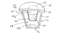
図1及び図2はそれぞれ、本発明の一つ又はそれ以上の局面を組み込んでいる描写的なカートリッジ10の側方断面図及び分解斜視図である。カートリッジ10は飲料マシンで使用され得て、茶、コーヒー、その他の浸出タイプの飲料、液体又は粉末状濃縮物から生成される飲料などの任意の適切な飲料を生成する。これより、カートリッジ10は、任意の適切な飲料媒質20、例えば挽いたコーヒー、茶葉、乾燥したハーブ茶、粉末状飲料濃縮物、乾燥果実抽出物又は粉末、粉末状又は液体濃縮ブイヨン又はその他のスープ、(粉末状ビタミン、薬、又はその他の調合薬などのような)粉末状又は液体医療材料、及び/又は(粉末状ミルク又はその他のクリーマー、甘味料、とろみ材、香料などのような)その他の飲料生成材料を含み得る。ある描写的な実施形態では、カートリッジ10は飲料媒質20を含み、これはコーヒー及び/又は茶飲料を生成するマシンでの使用のために構成されているが、しかし、本発明の局面はこれに限定されるものではない。
1 and 2 are a side cross-sectional view and an exploded perspective view, respectively, of an
この描写的な実施形態では、カートリッジ10は容器12を含み、これはフィルタ30によって分離された第1のチャンバ14a及び第2のチャンバ14bを有する内部空間14を含む。しかし、他の実施形態では、内部空間及び/又は第1及び第2のチャンバの領域のサブ部分又は領域における他の付加的なチャンバが設けられ得ることを理解されたい。例えば、カートリッジが3つの空間を有し、これらが2つのフィルタによって分離される(例えば、第1のフィルタは第1のチャンバの2つの空間を分離し、第2のフィルタは第1及び第2のチャンバを分離する)ことなどが可能である。他の実施形態では、第1又は第2のチャンバは、空気を飲料内に導入するベンチュリ又は他の形状によって、2つの部分に分離され得る。これより、第1及び/又は第2のチャンバは、フィルタ、壁、区画材、通路、及びその他の形状によって、2つ又はそれ以上の部分に区分され得るか、又はそうでなければ分離され得る。
In this illustrative embodiment, the
この実施形態では、容器12は、側壁17及び開口13を有する円錐台形状を有し得る。しかし、他の実施形態では、容器12は、縦溝付き、円錐状、又は円筒状の形状を有し得て、正方形又は長方形のカップの形状、ドーム状のカップ、球形又は球形の一部、又はその他の適切な形態であり得て、縦溝付き、波形、又はその他の形状の側壁などを有し得る。また、容器12は、いくつかの飲料サシェ(小袋)又はポッドにおける場合のように、必ずしも規定された形状を有している必要はない。例えば、この実施形態の容器12は比較的堅く及び/又は弾力のある構造を有し、容器12がその形状を維持する傾向にあるが、容器12は、例えば変形可能な材料のシートから形成されたサシェ容器のように、より追従性があり及び/又は変形し易い構成を有するように形成されることができる。これより、容器12によって規定される内部空間は、2つのフィルタ紙層(容器材料)が挽いたコーヒーの供給物の周囲で一緒に結合されてポッド又はその他の形状のカートリッジを作製するときと同様に、容器材料が飲料媒質、フィルタ、及び/又はその他のカートリッジ要素の周囲に形成された後にのみ、形成され得る。
In this embodiment, the
容器12が開口13を含むと、開口13は蓋38、例えば容器12の縁19に取り付けられたホイル及びポリマーラミネート材料によって、閉じられ得る。(この実施形態では、縁19は環状のフランジ状の要素として構成されているが、縁19は他の様式に構成され得る。例えば、縁19は、フランジ要素がない側壁17の上端であり得る。)容器12及び/又は蓋38は、湿気、及び/又は酸素のような気体に対するバリアを提供し得る。例えば、容器12はポリマーラミネート、例えば、ポリスチレン又はポリプロピレンの層、及びEVOH及び/又は金属ホイルのような他のバリア材料の層を含むシートから形成され得る。そのような構成は、飲料媒質20に対して、例えば湿気、酸素、及び/又は他の材料に対する望まれない曝露からの適切な保護を提供し得る。しかし、容器12及び/又は蓋38が、バイオポリマー、堆肥化可能なポリマー、紙、ホイルなどのような他の材料又は材料の組み合わせから作製され得ることを理解されたい。
Once the
本発明のある局面によれば、フィルタ30は、縁19から内向きに間隔を空けて離れた周縁32にて、蓋38に取り付けられ得る。加えて、フィルタ30は、周縁32から、少なくとも部分的に内部空間14へと延在し得る。上述のように、フィルタ30は内部空間14の第1及び第2のチャンバ14a及び14bの間に配置され得て、内部空間の第1のチャンバ14aの液体(例えば飲料媒質20と相互作用する)は、容器12を出る前に、フィルタ30を通過して内部空間14の第2のチャンバ14bに向かって流れる。フィルタ30は、液体からあるサイズを超える物質を除去するように機能し得て、例えば、挽いたコーヒーを第1のチャンバ14aの液体から除去し得て、コーヒー飲料がフィルタ30を通過して第2のチャンバ14bに向かうことを可能にする。例えば、フィルタは1枚の紙フィルタを含み得て、これは、液体とあるサイズの溶解した及び/又は懸濁した物質が通過することは可能にし、比較的大きな粒子がフィルタを通過することは妨げる。もちろん、フィルタ30は複数の段階を有してもよく、例えば、比較的大きな粒子をろ過する粗いフィルタ部と、それに続く比較的小さな粒子をろ過する微細フィルタ部などである。加えて、フィルタ30は、フィルタ30を通過する液体をろ過するように機能する一つ又はそれ以上の部分、および非浸透性か、又は他の方法で流れに抵抗する部分を含み得る。これより、フィルタ30は、望まれるならば、一つ又はそれ以上の別個の構成要素を含み得る。例えば、フィルタ30は、周縁32で蓋30に取り付けられた堅い非浸透性のプラスチックスリーブを含み得る。蓋38から離れた位置で、多孔性フィルタ紙がスリーブに取り付けられ得る。これより、フィルタの全ての部分が液体に対して浸透性である必要はない。フィルタ30はまた、異なる浸透度を有する領域を有していてもよく、例えば、フィルタ30の一つ又はそれ以上の領域に向かって流れを向けさせる手助けとなる。例えば、図1における蓋38に近いフィルタ30の領域は、蓋38からより離れた領域に比較して、比較的低い浸透度を有し得る。これは、フィルタ30の下方の領域に向かう飲料媒質20の流れを促進する手助けとなり、媒質20の材料の液体への溶解を改善することができる。
According to one aspect of the present invention, the
フィルタ30はまた、あるいは代替的に、第2のチャンバ14bから第1のチャンバ14aへの材料の動きを妨げる手助けをするように機能し得る。例えば、カートリッジ10は、第2のチャンバ14b内には飲料媒質20を収容し得るが、第1のチャンバ14a内には飲料媒質を収容しないかもしれない。この場合、フィルタ30は、飲料媒質20と、蓋38を穿孔して水又はその他の液体をカートリッジ10へ導入する針又はその他の液体流入口との接触を妨げる手助けをし得る。例えば、飲み物の粉末状混合材料のようないくつかの飲料媒質20は、針と接触が可能であると、流入口針を詰まらせるか又は詰まらせないまでも汚すことがある。フィルタ30は、そのような接触を妨げる手助けをし得て、カートリッジの適切な操作及び飲料の準備を維持する手助けとなる。
いくつかの実施形態では、フィルタ30は、(図1〜図3の実施形態のように)第1及び第2のチャンバ14a及び14bを分離する内部空間14内の唯一の要素であり得る。他の実施形態では、フィルタ30に加えて、壁、リブ、又はその他の構造物のような他の構成要素が、内部空間14の2つ又はそれ以上の部分をお互いに物理的に分離し得る。しかし、フィルタが構成される方法にかかわらず、フィルタ30の浸透性のある部分は、内部空間14の2つ又はそれ以上の部分を流れ幅に渡って分離又は区分する唯一の構成要素であり得る。例えば、液体は、フィルタ30の浸透性部分を流れて、第1のチャンバ14aから第2のチャンバ14bに通過する必要がある。
In some embodiments, the
この描写的な実施形態では、フィルタ30は、図示されているように、縦溝付き又はひだ付きの側壁と全体的に平らな底31とを有する実質的に円錐台形状を有し得る。しかし、フィルタ30は、円筒形状、正方形カップの形状、ドーム形状、平らなシート、又はその他のような任意の適切な形状を有し得る。フィルタ30は、接着剤、熱溶着、超音波溶着、化学結合、クリンプ又はその他の機械的な結合などのような任意の適切な方法で、蓋38に取り付けられ得る。理解されるように、周縁32の形状は、少なくともフィルタ30の上端におけるフィルタの形状に依存する。この実施形態では、周縁32は円形形状を有するが、楕円、長方形、三角形、不規則な又はその他の形状が可能である。この描写的な実施形態では、フィルタ30は、ポリプロピレンとセルロース材料との組み合わせからできた浸透性フィルタ紙を含み得て、熱溶着によってフィルタ30の上部にて蓋38に取り付けられ得る。図1〜図3にて見られるように、蓋38に取り付けられるフィルタ30の上部は、示されているように、周縁32から外向きに(又は他の実施形態では内向きに)半径方向に延在する環状又はワッシャ状の形状を有し得るが、そのような半径方向の延在は必要とはされない。いくつかの実施形態では、蓋38に取り付けられたフィルタの部分は、周縁から半径方向に外向きに、且つフィルタ30の一部が蓋38と縁19との間に挟まれるように縁19を越えて、延在し得る。
In this illustrative embodiment, the
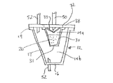
カートリッジ10を使用して飲料を生成するとき、蓋38及び/又は容器12は、カートリッジ内に液体を導入し且つ飲料をカートリッジから受容するために穿孔され得る。蓋38は、容器12を穿孔する場合の力より低い力で穿孔されるように構成され得る。(ここで使用されているように、「飲料」とは、液体が飲料媒質と相互作用するときに生成される飲用目的の液体材料を指す。これより、飲料は、消費の準備ができている、例えばカップに注入されて飲む準備ができている液体、および、消費される前に、ろ過、又は香料、クリーマー、甘味料、その他の飲料などの付加のような他のプロセス又は処理を受ける液体を指す。)液体をカートリッジ内に導入するために、例えば、図3に示されているように、概して周縁32によって縁取られた蓋38の一部が、流入口穿孔要素50(例えば針)によって穿孔され得て、水又はその他の液体がカートリッジ10に注入され得る。複数の針、シャワーヘッド、非中空針、円錐、角錐、ナイフ、刃などのようなその他の穿孔構成を採り得る。このカートリッジを使用する飲料マシンは、同じタイプ又は異なるタイプの複数の穿孔要素を含み得て、本発明はこの点に関しては限定されない。他の構成では、飲料マシンは、開口を形成する(大きな釘のような)穿孔要素を含み、形成された孔を(管のような)第2の流入口要素が、液体を容器内に導入する(又は液体をそこから導出する)ために通過し得る。他の実施形態では、蓋38は、蓋38の外部に圧力を導入することによって、穿孔されるか、又はその他の方法で効果的に流れのために開口され得る。例えば、水流入口が押し付けられて蓋38外部をシールし、その部分に水圧が導入される。水圧は、蓋38を穿孔させるか又はその他の方法で開口させて、カートリッジ10内への流れを可能にする。他の実施形態では、蓋38はバルブ、導管、又は適切な圧力にさらされたとき及び/又は水流入口チューブ又はその他の構造に対向したときに開口するその他の構造を含み得る。
When using the
カートリッジ10はまた、容器12の底16に、又は周縁32の外側であって流入口開口から離れた蓋38の第2の部分で、流出口穿孔要素52(例えば針)によって穿孔され得る。流入口穿孔構成においてのように、流出口穿孔構成は、任意の適切な様式に変更され得る。これより、流出口穿孔要素52は、一つ又はそれ以上の中空の又は中空ではない針、ナイフ、刃、管などを含み得る。あるいは、カートリッジ10は、液体をカートリッジ内に導入するときに開いて飲料が出ることを許容するが、そうでなければ閉まったままである(例えば、酸素、湿気、又はその他のもののような外部条件から飲料媒質を保護する)バルブ、隔膜、又はその他の要素を含み得る。そのような場合、流出口開口を形成するための穿孔要素は必ずしも必要とされないが、例えばバルブ又はその他の要素が開くことを可能にするために、使用され得る。また、この描写的な実施形態では、穿孔要素52は、容器12又は蓋38に形成された開口を出るときに飲料を受容するように、所定の位置のままである。しかし、他の実施形態では、穿孔要素52は、開口を形成した後に引き抜かれ、飲料がその開口から出て、カートリッジ10に延長されている穿孔要素52なしに受容されることを可能にする。
The
本発明のその他の局面では、カートリッジは、カートリッジに挿入された液体を飲料媒質に分配する手助けとなる、及び/又は流体流入口と飲料媒質との接触を防ぐ手助けとなる要素を含み得る。図1〜図3に示されている描写的な実施形態では、カートリッジは流れ分配器33を含み、これは流入口50と飲料媒質20との間に配置されている。この実施形態では、流れ分配器33は、到来する水又はその他の液体が、飲料媒質20をより均等に湿らせる手助けをし、加えて流入口50の飲料媒質との接触を阻止する手助けをするように機能する。もちろん、両機能の実行は必要とされず、例えば、流れ分配器33は液体のカートリッジ内への流れには影響するが、飲料媒質と流入口との接触を阻止しなくてもよい。飲料媒質20のより均一な濡れ、又はその他の流れ制御は、例えば、飲料媒質20内の物質をより完全に溶解することによって、また可溶性及び非可溶性物質の飲料媒質20からの抽出を改善することによって、さらにフィルタを通る飲料の流れを改善することによってなどで、カートリッジが所望の飲料を作り出す手助けとなることができる。飲料媒質20の流入口50との接触を低減することは、流入口の詰まり、及び/又は、流入口50に飲料媒質の一部が残されること(これは、流入口50が、異なるタイプの飲料媒質を有する異なるカートリッジを穿孔する場合に、生成される次の飲料の味に影響を与え得る)の可能性を低減する手助けをすることができる。
In other aspects of the invention, the cartridge may include elements that assist in dispensing the liquid inserted into the cartridge into the beverage medium and / or preventing contact between the fluid inlet and the beverage medium. In the illustrative embodiment shown in FIGS. 1-3, the cartridge includes a
この描写的な実施形態では、流れ分配器33は、フィルタ紙のような浸透性材料で構成され、これは、周縁32の内側の位置で蓋38に取り付けられている。これより、流れ分配器33は、液体が飲料媒質20を「トンネルする」原因となり得る到来液体の単一方向(あるいは2つ又はそれ以上の特定の方向)での流れを妨げる手助けをすることができる。そのような「トンネリング」は短絡を引き起こすことがあり、その場合には液体が飲料媒質20と十分に相互作用せずに、結果として許容できない劣等の製品がもたらされる。しかし、流れ分配器33は、飲料媒質20上に置かれた貫通孔が設けられたディスク、飲料媒質20の上に置かれた1枚のフィルタ紙、及びその他のもののような、他の形態を取り得る。これより、流れ分配器33は、蓋38又はフィルタ30に取り付けられる必要はなく、代わりに、単純に飲料媒質20とともに第1のチャンバ内に配置され得る。加えて、又はその代わりに、流入口針50又はその他の流体流入口は、例えば複数の流れを飲料媒質を横切るいくつかの異なる向きに向けることなどによって、水又はその他の液体を分配する手助けをするように構成され得る。流れ分配器33は、流入口針50によって接触されるように、又は、針50との接触を避けるように、配置され得る。流れ分配器33が針50と接触するならば、それは、流入口針50による流れ分配器33へのダメージを低減するほど十分に強靱な及び/又は十分に堅い材料を含み得る。そのような材料の非限定的な例は、フレキシブルであるが強靱な材料、堅いがもろい材料、延伸可能又は弾性があるが引き裂きに抵抗性を有する材料、強靱で且つ堅い材料などを含む。
In this illustrative embodiment, the
本発明のその他の局面は、上述のような及び/又は同様の特徴を有するカートリッジを使用した飲料の生成に関する。上述のように、カートリッジは様々な異なる構成を取り得るが、この描写的な実施形態では、図1〜図3に示されたものと同じ概略形態を有する。カートリッジは、冷水、炭酸水及び/又は加熱水をカートリッジに導入し、生成された飲料をカートリッジから受容することができる任意のもののような適切な飲料マシンと共に使用され得る。本発明の一つの局面では、カートリッジは、図4に概略的に示されているようにカートリッジが容器12の下方に蓋38があるように置かれながら、飲料を生成するために使用され得る。カートリッジ10は蓋38(又は蓋の一部)を水平面内又は鉛直面内に置いて使用されることができるが、本発明の一つの局面は、蓋38を、水平面を横切る平面内に、例えば水平面から約20〜70度の角度θにある平面内に置く。この方向はいくつかの効果を提供し得て、それは、飲料媒質のより完全な濡れ及び/又はカートリッジからの飲料のより完全な排出を含む。図4に示される姿勢は、カートリッジに導入された液体と飲料媒質20とのより良い濡れ又はその他の相互作用を可能にし得る。これは、液体がカートリッジ10の内部空間に「湛えられ」得て、例えば、第1のチャンバ14aと第2のチャンバ14bの少なくとも一部とを液体で満たすことで、飲料媒質20の全て又は大半が、液体が十分に染み込んだ状態となるからである。本発明のその他の局面によれば、カートリッジ10には排気口が設けられ得て、これは、飲料流出口から離れていて、液体で満たされるときにカートリッジからの気体の放出を許容する。排気口は、一方向バルブ(例えば、隔壁、アヒルのくちばし状のバルブ、又はその他のもの)によって設けられ得て、これは蓋38又は容器12に取り付けられてカートリッジ10内の圧力の上昇に反応して開き、蓋38(図4に示されるように)又は容器12を穿孔して気体及び/又は液体を逃す穿孔要素54、及びその他の構成によって設けられ得る。(要素54がカートリッジ10に対する排気口を提供するように記述されているが、要素54は、カートリッジの排気に加えて又はそれに代えて、他の機能も提供し得る。例えば、要素54は代替的な液体流入及び/又は流出路を提供し得て、及び/又は、カートリッジ10に空気圧を導入して、例えば飲料生成サイクルの最後で任意の残存する飲料をカートリッジ10からパージする手助けとなるために使用され得る。また、要素54が単一の穿孔針として示されているが、要素54は流入口及び流出口要素50及び52のように他の方法で構成され得る。例えば、要素54は一つ又はそれ以上の刃、管、ナイフ、中空ではない又は中空の針、などを含み得て、排気、液体流入口又は流出口、及び/又はパージ機能を提供する。)
Another aspect of the present invention relates to the production of beverages using cartridges having the above and / or similar characteristics. As described above, the cartridge may take a variety of different configurations, but in this illustrative embodiment, it has the same schematic form as shown in FIGS. The cartridge can be used with any suitable beverage machine such as any that can introduce cold, carbonated and / or heated water into the cartridge and receive the resulting beverage from the cartridge. In one aspect of the invention, the cartridge can be used to produce a beverage while the cartridge is placed with a
蓋38を、水平面を横切る平面内に置くことはまた、カートリッジ10からの飲料のよりよい排出を可能にする。すなわち、カートリッジ10が傾いていてカートリッジの片側が他方より低いので、飲料はカートリッジの低い側に排出される傾向にあり得る。また、飲料流出口の開口は低い側に又はその近くに形成され得て、カートリッジ10内の全ての又は大半の飲料が除去されることができる。この特徴は少なくとも2つの恩恵を提供し得て、それは、ユーザがカートリッジを飲料マシンから除去するときのたれ又は望まれない漏れの低減、及び/又はカートリッジ内にほとんど又は全く飲料が残されないことによるより完全且つ効率的な飲料媒質の使用を含む。
Placing the
上述の実施形態は飲料媒質20を第1のチャンバ14aのみに収容しているが、これらの実施形態は(第1のチャンバ14a内にあるものと同じ又は異なる)飲料媒質を第2のチャンバ14b内に、又はカートリッジの他の部分に収容し得る。例えば、カートリッジはローストされ且つ挽いたコーヒーを第1のチャンバ14aに、およびクリーマー及び甘味料を第2のチャンバ14bに収容し得て、カートリッジがカプチーノ又はラテのような飲料を生成することを可能にする。他の実施形態では、第1のチャンバ14aは挽いたコーヒーを収容し得て、第2のチャンバ14bはホットチョコレート材料を収容し得て、カートリッジがモカタイプの飲料を生成することを可能にする。第1のチャンバに葉茶で第2のチャンバに乾燥果実材料、第1のチャンバに乾燥果実材料で第2のチャンバにクリーマー/甘味料などのような他の組み合わせが、当業者には生じるであろう。いくつかの実施形態では、他のフィルタが提供され得て、例えば第2のチャンバ内の飲料媒質を流体流出口から分離する。例えば、フィルタは、流出口針が蓋38を穿孔する領域で蓋38に取り付けられ得て、飲料が、付加的なフィルタを通過した後のみにカートリッジを出ることを可能にする。
Although the embodiments described above contain the
上述のように、本発明の局面は、異なる形状、サイズ、及び/又は構成を有するカートリッジで具現化され得る。例えば、図5はカートリッジ10の描写的な実施形態を示しており、これは、比較的可撓性のある材料(例えば薄いポリマーシート材料)でできた容器12に設けられた(例えばプラスチック材料でできた環状形状の要素を含む)比較的堅い又は曲がらない縁19を含む。縁19の上面には蓋38及びフィルタ30が取り付けられていて、これらは図1〜図3の実施形態におけるものと同様に配置され得る。すなわち、蓋38は、比較的可撓性のある材料(例えばホイルシート)で形成され得て、縁19から内側に間隔を空けた周縁32で蓋38に取り付けられたフィルタ紙でできたフィルタ30を有する。飲料媒質20(図示せず)はフィルタ30の内側に(及び/又は容器12内のフィルタの外側に)収容され得て、オプションの流れ分配器33(図示せず)が、所望であれば設けられ得る。この実施形態は、例えば容器12に対して使用される材料の量がより少ないために、重量及び材料使用量の低減のような効果を提供し得る。また、カートリッジ10が構造的な支持を必要とする(例えば流入口及び流出口開口のため蓋38に適切な穿孔を可能にするために)限りにおいて、縁19は、容器12からの手助けなしに必要とされる支持を提供し得る。これより、図5のカートリッジは、図4に示されるような方向で使用されることができ得て、蓋38及びフィルタ30は、所望であれば縁19及び容器12から(例えば剥離によって)除去され得る。
As described above, aspects of the present invention may be embodied in cartridges having different shapes, sizes, and / or configurations. For example, FIG. 5 shows an illustrative embodiment of the
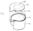
図6は、本発明の局面を組み込んだカートリッジ10のその他の描写的な実施形態を示す。この実施形態では、カートリッジ10は蓋38(例えばホイル/ポリマーラミネートシートを含む上述のようなもの)を含み、これは周縁32でフィルタ30に取り付けられている。しかし、この実施形態では、フィルタ30は非浸透性の円筒状部材34を含み、これが蓋38及び円筒状部材34の底に取り付けられた浸透性フィルタ紙35から延在している。蓋38及びフィルタ30は縁19及び容器12に、例えば蓋38を縁19に結合してフィルタ30が容器12の内部空間に位置するようにすることによって、縁19及び容器12に関連されている。容器12は任意の適切な形状、例えば、モールド(型成形)されたプラスチック材料で形成されたカップ状の部材を含み得る。飲料媒質20は円筒状部材34内に配置され得て、液体が円筒状部材34内に導入されると、飲料はフィルタ紙35を通過し得る。あるいは、飲料媒質20は容器12に且つフィルタ30の外側に提供され得る。この場合、フィルタ30は、飲料媒質20が液体流入口に接触することを妨げる手助けとなり得て、及び/又は、飲料媒質20をカートリッジ内の特定の構成内に維持する手助けとなり、例えば、飲料媒質20が容器12の側壁及び底に対して詰められた状態にされ続ける手助けとなり得る。飲料媒質20がフィルタ30の外側にあると、水又はその他の液体は、フィルタ30の外側の領域からカートリッジ内に(例えば周縁32の外側で蓋38の一部から第2のチャンバ14bに)導入され得て、飲料は、フィルタ30の外側の領域から(例えば)周縁32の内側の蓋38の開口を介して第1のチャンバ14aから)カートリッジを出てもよい。
FIG. 6 illustrates another illustrative embodiment of a
この実施形態は、フィルタ30が2つ又はそれ以上の構成要素からできており、非浸透性の部分および浸透性の部分を含み得ることを説明する手助けとなる。非浸透性の部分は、液体が所望の方法で流れるようにし向ける手助けをし得る。例えば、図6の場合には、蓋38の開口を介して導入された液体は、フィルタ紙35を出る前に、円筒形部材34の長さに沿って移動しなければならない。他の実施形態では、円筒形部材34は浸透性、フィルタ紙35は非浸透性とされ得て、液体は円筒形部材34のみを通過して流れる。他の実施形態では、円筒形部材34の一つ又はそれ以上の部分が非浸透性であり得て(例えば、蓋38に近い円筒形状の帯は非浸透性であり得る)、一つ又はその以上のその他の部分が浸透性であり得る(例えば、フィルタ紙35に近い円筒形状の帯は浸透性であり得る)。もちろん、これらはいくつかの描写的な実施形態に過ぎず、他の配置も可能である。例えば、円筒形部材34の形状、サイズ、又は構成は、例えば四角形、三角形、円錐台形状、球形、又はその他の形状に、変更され得る。また、フィルタ紙35は任意の形状、サイズ、又は配置を有し得て、例えば、平坦及び円形である必要はなく、貫通孔付きプラスチックディスクのようなその他の浸透性要素で置き換えられ得る。要するに、フィルタ30は、任意の適切な方法で配置され得る。
This embodiment helps to explain that the
図7は、四角形形状を有するカートリッジ10の他の描写的な実施形態を示す。この実施形態では、容器12は方形の箱のような形状であり、四角形形状の縁19を有する。蓋38及びフィルタ30(これらもまた方形の箱のような形状を有する)は、上述されたものと同様の方法で、縁19に取り付けられている。この実施形態は、本発明の局面が、縁19及び/又はその他のカートリッジ構成要素に対して曲線状又は円形に限定されないことを示している。逆に、カートリッジ構成要素に対する任意の不規則な又はその他の適切な形状が可能である。例えば、図8は、注ぎ口のような形状を有するカップ形状を形成する縁19及び容器12を有するカートリッジ10の実施形態を示す。蓋38は、対応する形状を有し得て、流出口開口が縁19及び容器12の注ぎ口領域にて蓋38に形成されることができるように配置され得る。これは、例えばカートリッジの適切な方向付けで、飲料が注ぎ口領域に排出される傾向があり得るので、容器12からの飲料の排出の手助けとなり得る。注ぎ口形状又はその他の不規則な形状はまた、カートリッジ10が特定の方法で飲料マシンに関連付けられることを確実にする手助けとなる目印又は位置決め形状も提供し得る。例えば、図8に示されるカートリッジは、図4に示されるような方向で使用され得て、その場合には、注ぎ口形状は流出口52に又はその近くに位置される。注ぎ口は、カートリッジが流出口52に又はその近くに注ぎ口を有するように位置されることを確実にするために使用されることができるので、注ぎ口は、飲料のカートリッジから流出口52への排出を手助けすることができる。注ぎ口又はその他の目印となる形状を使用してカートリッジの方向付けを確実にすることはまた、カートリッジ10がバーコード、RFIDタグ、又はその他の機械読み取り可能コードのような読み取り可能な特徴物を含むときにも、手助けとなり得る。すなわち、注ぎ口は、読み取り可能な特徴物(単数又は複数)が機械によって適切に読み取られることができるようにカートリッジが回転的に特定の位置に配置されることを確実にする手助けとなり得る。注ぎ口形状(又はその他の適切な構成)はまた、蓋38及びフィルタ30が縁19から、例えば蓋38を縁19から剥離することによって除去され得るように、プルタブが蓋38に対して配置されるための便利な場所も提供する。
FIG. 7 shows another illustrative embodiment of a
図9は、カートリッジ10のさらにその他の描写的な実施形態を示しており、ここでは、蓋38が2つの構成要素を含んでいる。具体的には、蓋38は、縁19に取り付けられた外側部分38aと、(例えば飲料媒質がフィルタ30によって規定される空間に提供された後に)その外側部分38aに取り付けられる内側部分38bとを含む。この実施形態は、蓋の少なくとも一部が、飲料媒質20のカートリッジ10内への配置に先立って縁19及び容器12に取り付けられることを可能にするという利点を提供し得る。すなわち、蓋38の外側部分38aは、外側部分38aに取り付けられたフィルタ30と一緒に縁19に取り付けられ得るが、そのとき蓋38の内側部分38bは所定の位置にはない。その後に、飲料媒質20が外側部分38aの開口を通して提供され得て、内側部分38bが開口を閉じるように外側部分38aに取り付けられる。外側部分38a及び内側部分38bは異なる材料で形成され得て、例えば、外側部分38aは比較的厚く曲げ難いプラスチック材料で形成され得て、内側部分38bは比較的薄く可撓性のあるホイル材料で形成され得る。この場合、外側部分38aはカートリッジ10に対して構造材を提供し得て、縁19が比較的可撓性がありで且つ/又は薄い材料で形成されることを可能にし、例えば、縁19は、容器12の外側部分38aに結合された部分であってもよく、容器12は薄いポリマーシート材料で形成されている。
FIG. 9 shows yet another illustrative embodiment of the
本発明の局面に従ったカートリッジは、任意の適切な飲料マシンとともに使用され得る。例えば、図10は、茶、コーヒー、他の浸漬タイプの飲料、液体又は粉末状の濃縮物から生成される飲料、ホット又は冷たい飲み物などのような任意の適切な飲料を生成するために使用され得る飲料生成装置100の斜視図を示す。この描写的な実施形態では、装置100は、ユーザが装置100の様々な特徴を制御するように操作し得るユーザーインターフェース8を有する外側フレーム又はハウジング6を含む。飲料カートリッジ10は装置100に設けられ得て、もしあればドリップトレイ9又はその他の支持体に置かれたカップ又は他の適切な受容体に注がれる飲料を生成するために使用され得る。カートリッジ10は、飲料生成装置100の第1及び第2の部分3及び4によって規定されるカートリッジ受容部分に手作業で又は自動的に置かれ得る。例えば、ハンドル5を持ち上げることによって、ユーザは第1及び第2の部分3及び4を開位置に動かして、カートリッジ10がそこに置かれ得る適切な形状をした領域を露出させ得る。カートリッジ10の設置後に、ハンドル5又はその他のアクチュエータが手作業又は自動様式で動かされ得て、第1及び第2の部分3及び4を閉位置に動かし(図10に示されている)、それによって少なくとも部分的に抽出チャンバ内にカートリッジ10を閉じる。しかし、カートリッジ10が、装置100がカートリッジ10を受容するか又はその他の方法で使用する仕方は本発明の局面にとって重要ではないので、カートリッジ10が装置100によって任意の適切な方法で受け取られ得ることを理解されたい。
A cartridge according to aspects of the present invention may be used with any suitable beverage machine. For example, FIG. 10 is used to produce any suitable beverage such as tea, coffee, other soaking type beverages, beverages produced from liquid or powdered concentrates, hot or cold beverages, etc. The perspective view of the drink production |
カートリッジ10がひとたび受容されると、飲料生成装置100は、カートリッジ10を使用して飲料を生成し得る。例えば、第1又は第2の部分3、4に関連した一つ又はそれ以上の流入口針50(図3又は図4を参照)が、加熱された水又はその他の液体をカートリッジ10に注入するようにカートリッジ10を穿孔し得る。第1又は第2の部分3、4はまた、一つ又はそれ以上の流出口針又はその他の要素52を含み得て、(必要なときには)流出口側でカートリッジ10に孔を開けるか又は穿孔して、生成された飲料がカートリッジ10を出ることを可能にする。
Once the
図11は、飲料生成装置100にて使用され得る抽出チャンバの構成の模式図を示す。この描写的な実施形態では、第1の部分3はクランプ21を含み、これがカートリッジ受容器22に対して可動である。第2の部分4はベース51を含み、これもまたカートリッジ受容器22に対して可動で、流入口針及び流出口針50及び52を有する。カートリッジ10を抽出チャンバ内に囲み込むために、カートリッジ10はまずカートリッジ受容器22内に置かれて、カートリッジは受容器22によって静止して保持される。この実施形態では、受容器22は溝を含み、これがカートリッジ10の縁19と係合するが、受容器22が、容器12を係合することによってのように他の方法でカートリッジを保持してもよい。その後に、クランプ21及びベース51がカートリッジ受容器22に向かって移動されて、クランプ21がカートリッジ10の縁19に係合して、縁19をベース51に押し付けて接触させる。この係合は、ベース51と縁19と蓋38との間のシールを形成する手助けとなり得て、例えば、液体の流入口又は流出口針50及び52からの漏れを防ぐ手助けとなる。縁19/蓋38をベース51に接触するように押し付けることはまた、針50及び52に蓋38を穿孔させて、流入口及び流出口開口を形成する。カートリッジが適切に保持されると、水又はその他の液体がカートリッジ10内に流入口針50によって導入され、飲料が流出口針52によってカートリッジから受容される。
FIG. 11 shows a schematic diagram of a configuration of an extraction chamber that can be used in the
当業者は、この描写的な抽出チャンバの構成に対する様々な改変がなされ得ることを理解すべきである。例えば、ベース51は2つ又はそれ以上の流入口又は流出口針50及び52を有し得て、針50及び52は、流入口/流出口流れ及び/又は任意の他の適切な流入口及び流出口配置のためにナイフ、刃、円錐構造、一つ又はそれ以上の管、ベース51の開口によって置き換えられ得て、穿孔要素(設けられるならば)は、ベースに関して引き込み可能にされ得て、ベース51は静止したままにされ得て且つカートリッジがベース51に対して動かされ得る、などである。同様に、クランプ21は、示されているリング状の形状の他に任意の適切な形状を有し得て、例えば、クランプ21はカップ状の形状を有し得て、クランプ21は静止したままにされ得て且つカートリッジ10及び/又はベース51がクランプ21に対して動かされ得て、クランプ21及び容器保持器22は一緒に一体化される、及びその他のものである。また、この実施形態では、カートリッジ保持器22は、(図4のものと同様に)カートリッジ10を蓋38が容器12の下方にある逆さの姿勢に保持しているが、カートリッジは飲料を任意の適切な方向で生成するために使用され得る。
One of ordinary skill in the art should understand that various modifications to the configuration of this descriptive extraction chamber can be made. For example, the
図12は、図10のもののような一つの描写的な実施形態における飲料生成装置100に含まれる様々な構成要素の模式的なブロック図である。当業者は、飲料生成装置100が様々な異なる方式で構成され得て、これより本発明の局面が一つのタイプの飲料生成装置のみに関して狭く解釈されるべきではないことを理解するであろう。貯蔵タンク110からの水又はその他の液体は、供給導管111を介して、液体をポンプ導管115を介して計量タンク又はチャンバ118にポンプする(遠心ポンプ、ピストンポンプ、ソレノイドポンプなどのような)ポンプ112に提供され得る。装置100の水ポンプ112及びその他の構成要素の操作は、コントローラ130によって制御され得て、これは例えば、適切なソフトウエア又はその他の動作指令とともにプログラムされたプロセッサ及び/又は他のデータ処理装置、一つ又はそれ以上のメモリ(ソフトウエア及び/又はその他の操作指令を記憶し得る非一過性記憶媒体を含む)、温度及び液体レベルセンサ、圧力センサ、入力/出力インターフェース、通信バス又はその他のリンク、ディスプレー、スイッチ、リレー、トライアック、又はその他の所望の入力/出力又はその他の機能を実行するために必要な構成要素を含む。計量タンク118は、所定の時間だけポンプ112を稼動させる、計量タンク118内の水レベルを導電プローブセンサ又は容量性センサを使用してセンシングする、液体がタンクを満たしているときに計量タンク118内の圧力上昇を検出する、又は任意の他の現実的な技法を使用するような任意の適切な技法によって、所望の量の液体で満たされ得る。例えば、コントローラ130は、水が計量タンク118の頂部に到達したことを示す圧力の上昇を圧力センサが検出したときに、計量タンク118が完全に満たされたことを検出し得る。タンク内の水は、所望であれば、加熱要素123によって加熱され、その操作は、温度センサからの入力又はその他の適切な入力を使用してコントローラ130によって制御される。計量タンク118内の水は、計量タンク導管119を介して抽出チャンバ120又はその他の飲料生成ステーションに排水され得る。抽出チャンバ120は、例えばカートリッジ10に含まれた挽いたコーヒー、茶、香料付きの飲み物のミックス、又はその他の物質のような任意の飲料生成成分を含み得る。液体は、計量タンクを空気ポンプ121によって提供される空気で加圧して液体をチューブ117から計量タンク導管119内に放出させることによって、計量タンク118から放出され得る。計量タンク118からの注出の完了は、計量タンク118内の圧力低下を検出することによって、計量タンク118内の水レベルの変化を検出することによって、流量計の使用、又は任意の他の現実的な技法の使用によって、任意の適切な方法で検出され得る。あるいは、液体は、追加の液体をタンク118内に入れさせて、それによってタンク118から水を抽出チャンバに移させるように動作するポンプ112によって、計量タンク118から排水され得る。流量センサ又はその他の適切な装置が、タンク118に送達された液体の量、及びこれより抽出チャンバに送達された液体の量を決定するために使用され得る。あるいは、ポンプ12がピストンタイプ又は計量ポンプであり得て、既知の容積の液体がポンプ112からタンク118に送達され得て、これによって同じ既知の容積を抽出チャンバ120に送達させる。液体は、任意の適切な圧力で、例えば1〜2psi又はそれ以上で、カートリッジ10内に導入され得る。
FIG. 12 is a schematic block diagram of various components included in a
本発明の他の局面は、カートリッジを製造する方法を含む。一つのそのような描写的な方法のステップが、図13に示されている。(図13及び図14のステップは、以下により詳細に記述されるように、本方法のステップが図示されているものとは異なる順で実行され得ることを示すように、破線で接続されて示されている。)ステップS10で、内部空間と内部空間への開口を規定する縁とを有する容器が準備される。容器は、プラスチック、紙、金属、及び材料の組み合わせのような任意の適切な材料から形成され得る。一般的に、容器は液体に対して非浸透性で、カートリッジ内に作られた飲料は制御された方法で取り除かれることができるが、浸透性の部分を有してもよい。また、容器は、円錐台形状、球形、円筒状、四角形の箱、などのような任意の適切な形状を有し得る。さらに、容器は規定された形状を有している必要はなく、その代わりに、可撓性材料で形成され得る。 Another aspect of the invention includes a method of manufacturing a cartridge. One such descriptive method step is shown in FIG. (The steps of FIGS. 13 and 14 are shown connected in dashed lines to indicate that the steps of the method may be performed in a different order than that shown, as described in more detail below. In step S10, a container having an internal space and an edge defining an opening to the internal space is prepared. The container may be formed from any suitable material such as plastic, paper, metal, and combinations of materials. Generally, the container is impermeable to liquids and the beverage made in the cartridge can be removed in a controlled manner, but may have a permeable portion. The container may also have any suitable shape such as a frustoconical shape, a spherical shape, a cylindrical shape, a rectangular box, and the like. Further, the container need not have a defined shape, but can instead be formed of a flexible material.
ステップS20で、フィルタが蓋に周縁にて取り付けられる。周縁は閉じた境界線であって、そこで、フィルタが蓋に取り付けられて、且つ蓋から離れる向きに延在する(例えば容器の内部空間に)。フィルタは、フィルタ紙、浸透性又は非浸透性のプラスチック材料、スポンジ状の材料、などのような任意の適切な材料を含み得る。また、フィルタは、非浸透性および浸透性要素を含み得る。例えば、非浸透性プラスチック要素は蓋に取り付けられ得て、フィルタ紙又はプラスチック要素に取り付けられたその他の材料に対する構造的な支持体を提供する。フィルタは、任意の適切な形状、サイズ及び/又は浸透性を有することができる。例えば、フィルタは、フィルタのある領域を通る流れを妨げるか又は制限し、その他のより浸透性のある領域を通る流れを促進するように、異なる浸透度の領域を有し得る。一般的に、フィルタは容器には取り付けられておらず、例えば、フィルタ及び蓋は、リサイクル及び/又は堆肥化プロセスのために容器から取り外されることができる。しかし、いくつかの実施形態では、フィルタは縁に取り付けられ得て、例えば、フィルタの一部が蓋と縁との間に挟まれ得る。 In step S20, the filter is attached to the lid at the periphery. The perimeter is a closed boundary where the filter is attached to the lid and extends away from the lid (eg, into the interior space of the container). The filter may comprise any suitable material such as filter paper, permeable or non-permeable plastic material, sponge-like material, and the like. The filter may also include non-permeable and permeable elements. For example, a non-permeable plastic element can be attached to the lid to provide a structural support for filter paper or other materials attached to the plastic element. The filter can have any suitable shape, size and / or permeability. For example, the filter may have regions of different permeability so as to prevent or limit flow through certain areas of the filter and facilitate flow through other more permeable areas. Generally, the filter is not attached to the container, for example, the filter and lid can be removed from the container for recycling and / or composting processes. However, in some embodiments, the filter can be attached to the edge, for example, a portion of the filter can be sandwiched between the lid and the edge.
ステップS30で、蓋が縁に取り付けられて(例えば少なくとも部分的に開口を閉じて)、周縁が縁から間隔を空けて離れて且つフィルタが周縁から内部空間内へと延在する。フィルタは、内部空間内で第1のチャンバを第2のチャンバから分離するように配置され得る。蓋は、熱的又は音響的溶着、接着剤、化学結合、機械的結合、などのような任意の適切な方法で、縁に取り付けられ得る。いくつかの実施形態では、縁は溝又はその他の形状を含み得て、これが蓋の縁からの取り外しを手助けする。蓋は、ホイル、ホイル及びポリマーのラミネート、ポリマー材料、などのような任意の適切な材料から形成され得て、浸透性又は非浸透性であり得る。しかし、蓋は一般的に、非浸透性の材料から形成され得て、カートリッジへの液体の流れの制御を手助けする。 In step S30, a lid is attached to the edge (eg, at least partially closing the opening), the periphery is spaced from the edge, and the filter extends from the periphery into the interior space. The filter may be arranged to separate the first chamber from the second chamber within the interior space. The lid can be attached to the edge in any suitable manner such as thermal or acoustic welding, adhesives, chemical bonds, mechanical bonds, and the like. In some embodiments, the edge may include a groove or other shape that assists in removal from the lid edge. The lid can be formed from any suitable material, such as foil, foil and polymer laminates, polymeric materials, etc., and can be permeable or non-permeable. However, the lid can generally be formed from a non-permeable material to help control the flow of liquid to the cartridge.
ステップS40で、飲料媒質がカートリッジの内部空間に、例えばフィルタによって第2のチャンバから分離された第1のチャンバ内に、提供される。飲料媒質は、容器内に導入された液体と相互作用して飲料を生成するように配置され得て、且つ、ローストされた挽いたコーヒー、葉茶、インスタントコーヒー又は茶、ホットチョコレート粉末状混合物、飲み物の粉末状混合物、乾燥果実材料、甘味料、クリーマー、とろみ材、及び/又は飲料を生成するための任意の他の適切なる材料を含み得る。 In step S40, a beverage medium is provided in the interior space of the cartridge, for example in a first chamber separated from the second chamber by a filter. The beverage medium can be arranged to interact with the liquid introduced into the container to produce a beverage and roasted ground coffee, leaf tea, instant coffee or tea, hot chocolate powder mixture, It may include a powdered mixture of drinks, dried fruit material, sweeteners, creamers, thickeners, and / or any other suitable material for producing a beverage.
図13で概説された方法のステップが任意の適切な順序で実行され得ることを理解されたい。例えば、ある実施形態では、飲料媒質は、フィルタが蓋に取り付けられる前に、フィルタによって規定される空間内に提供され得る。他の実施形態では、飲料媒質は、フィルタが蓋に取り付けられた後に、フィルタによって規定される空間内に提供され得る。例えば、蓋は蓋に取り付けられ得て、飲料媒質は、フィルタの開口を通して、フィルタによって規定された空間に提供される。その後に、フィルタの開口は、例えば開口の周囲でフィルタの端をお互いにシールすることによって、閉じられ得る。他の実施形態では、フィルタは蓋に、例えば図9に示されるもののように取り付けられ得て、飲料媒質は、蓋が容器の縁に取り付けられる前又は後のいずれかに、フィルタによって規定された空間に提供される。 It should be understood that the method steps outlined in FIG. 13 may be performed in any suitable order. For example, in certain embodiments, the beverage medium can be provided in the space defined by the filter before the filter is attached to the lid. In other embodiments, the beverage medium may be provided in the space defined by the filter after the filter is attached to the lid. For example, the lid can be attached to the lid, and the beverage medium is provided through the opening of the filter to the space defined by the filter. Thereafter, the openings of the filter can be closed, for example by sealing the ends of the filter together around the opening. In other embodiments, the filter can be attached to a lid, such as that shown in FIG. 9, and the beverage medium is defined by the filter either before or after the lid is attached to the edge of the container. Provided in space.
本発明の他の局面は、例えば図14に概説されているように、飲料を生成する方法に関する。ステップS50で、容器を有するカートリッジが提供され、これは、内部空間と内部空間への開口を規定する縁と縁に取り付けられて容器の開口を閉じる蓋と縁から内側に間隔を空けて離れている周縁で蓋に取り付けられるフィルタと、を含む。フィルタは、周縁から内部空間へと延在して、内部空間内で第1のチャンバと第2のチャンバとを分離する。飲料媒質は内部空間に、例えば第1及び/又は第2のチャンバに配置されて、容器内に導入された液体と相互作用して飲料を生成するように構成される。上述のように、容器、縁、蓋及びフィルタは、任意の適切な材料から任意の適切な方法で形成され得る。同様に、飲料媒質は、飲料を生成するための任意の適切な材料を含み得る。 Another aspect of the invention relates to a method of producing a beverage, for example as outlined in FIG. In step S50, a cartridge having a container is provided, which is attached to the edge defining the interior space and the opening to the interior space and a lid that closes the container opening and spaced inwardly from the edge. And a filter attached to the lid at a peripheral edge. The filter extends from the peripheral edge to the internal space and separates the first chamber and the second chamber within the internal space. The beverage medium is disposed in the interior space, for example in the first and / or second chamber, and is configured to interact with the liquid introduced into the container to produce a beverage. As described above, the container, rim, lid and filter may be formed from any suitable material in any suitable manner. Similarly, the beverage medium may include any suitable material for producing a beverage.
ステップS60で、蓋が、例えば蓋の中心の近くで且つ縁からは離れて穿孔されて、第1のチャンバにアクセスするための第1の開口が形成される。蓋の穿孔は、針、刃、ナイフ、又はその他の適切な物体を蓋に挿入することによって、水又はその他の圧力を蓋に導入して蓋を破裂させることによって、あるいは流れを開くバルブ又はその他の構造などによって、なされ得る。ステップS70で、液体が第1の開口を介して、例えば、加熱された、加圧された水を第1の開口を形成するために蓋に穿孔した針を通して注入することによって、第1のチャンバに導入される。第1の開口を通して管を挿入する、プレート又はその他の部材における開口を第1の開口の近くの蓋に対向させる、などの他の技法が、液体を導入するために使用され得る。 In step S60, the lid is pierced, for example near the center of the lid and away from the edge, to form a first opening for accessing the first chamber. Lid drilling can be done by inserting a needle, blade, knife, or other suitable object into the lid, introducing water or other pressure into the lid to rupture the lid, or opening a flow valve or other This can be done depending on the structure. In step S70, the liquid is injected into the first chamber through the first opening, for example by injecting heated, pressurized water through a needle drilled in the lid to form the first opening. To be introduced. Other techniques can be used to introduce liquid, such as inserting a tube through the first opening, or making the opening in the plate or other member opposite the lid near the first opening.
ステップS80で、液体の飲料媒質との相互作用によって生成された飲料が、フィルタを通って第2のチャンバに流れる。フィルタを通る飲料の流れは、比較的大きな粒子の、挽いたコーヒー、茶の葉、又はその他のもののような粒子状の物体を飲料から除去し得る。ステップS90で、蓋が穿孔されて第2のチャンバにアクセスするための第2の開口が形成され、この第2の開口は第1の開口よりも縁に近く且つ周縁と縁との間に位置されている。上述のように、穿孔要素は穿孔後にカートリッジと係合したままでもよく、あるいは、飲料が形成された開口から出ることができるように引き抜かれてもよい。最後に、ステップS100で、飲料がカートリッジから第2の開口を介して取り除かれる。 In step S80, the beverage produced by the interaction with the liquid beverage medium flows through the filter to the second chamber. The beverage flow through the filter may remove relatively large particles of particulate matter such as ground coffee, tea leaves, or the like from the beverage. In step S90, the lid is pierced to form a second opening for accessing the second chamber, the second opening being closer to the edge than the first opening and between the periphery. Has been. As described above, the piercing element may remain engaged with the cartridge after piercing or may be withdrawn so that the beverage can exit the opening in which it was formed. Finally, in step S100, the beverage is removed from the cartridge through the second opening.
図14に概説された方法は、液体の第1のチャンバへの導入に先立って縁をクランプ機構で係合するステップのような、追加のステップを含み得る。例えば、カートリッジは、抽出の間に蓋が縁から分離する可能性を低減するような及び/又は漏れの可能性を低減するような位置にカートリッジの縁がクランプされるように、図11におけるもののような抽出チャンバ構成によって係合され得る。蓋及び/又は容器はまた、内部空間を排気するための第3の開口を形成するためにも穿孔され得る。これは、カートリッジの内部空間を液体で溢れさせる手助けをするために、有用であり得る。カートリッジは、例えば図11に示されているように、蓋の上方に容器があって且つ蓋が水平面を横切る平面内にあるように、蓋が下方を向く姿勢となるように置かれ得る。蓋が向けられる平面は、水平面に対して約20度から70度の角度であり得て、これは上述の飲料生成を手助けし得る。カートリッジは、例えば蓋と飲料媒質との間で蓋に取り付けられた流れ分配器を含み得て、カートリッジに導入された液体を所望の方法で分配する手助けとなる。飲料の生成に引き続いて、蓋が手によって縁から剥がされ、蓋、フィルタ及び飲料媒質を単一のユニットとして容器から取り除く。例えば、蓋はタブ又はその他の構造を有し得て、これが親指と人差し指との間でつままれて、蓋をカートリッジの縁から剥がすために使用され得る。フィルタ及び飲料媒質は蓋に取り付けられているので、飲料生成後のフィルタ及び飲料媒質の残りは、容器から容易に取り除かれて、例えば容器がリサイクルされて、飲料媒質及びフィルタは堆肥化される。 The method outlined in FIG. 14 may include additional steps, such as engaging the edges with a clamping mechanism prior to introduction of liquid into the first chamber. For example, the cartridge may be that of FIG. 11 such that the cartridge edge is clamped in a position that reduces the likelihood of the lid separating from the edge during extraction and / or reduces the likelihood of leakage. It can be engaged by such an extraction chamber configuration. The lid and / or container can also be pierced to form a third opening for evacuating the interior space. This can be useful to help flood the interior space of the cartridge with liquid. The cartridge can be placed so that the lid is in a downward orientation, for example, as shown in FIG. 11, with the container above the lid and the lid in a plane transverse to the horizontal plane. The plane to which the lid is directed can be at an angle of about 20 to 70 degrees with respect to the horizontal plane, which can aid in the beverage production described above. The cartridge can include, for example, a flow distributor attached to the lid between the lid and the beverage medium to help dispense the liquid introduced into the cartridge in the desired manner. Following the production of the beverage, the lid is peeled off the edge by hand and the lid, filter and beverage medium are removed from the container as a single unit. For example, the lid can have a tab or other structure that can be pinched between the thumb and index finger and used to peel the lid off the edge of the cartridge. Since the filter and beverage medium are attached to the lid, the remainder of the filter and beverage medium after the beverage has been produced is easily removed from the container, for example, the container is recycled and the beverage medium and filter are composted.
また、図14で概説された方法のステップは、図14に示されているものとは異なる順序で実行され得る。例えば、ステップS60及びS90は同時に実行されてもよく、あるいは、ステップS90はステップS60の前に実行されてもよい。 Also, the method steps outlined in FIG. 14 may be performed in a different order than that shown in FIG. For example, steps S60 and S90 may be executed at the same time, or step S90 may be executed before step S60.
このように本発明の少なくとも一つの実施形態のいくつかの局面が述べられてきたが、様々な変更、改変、及び改良が当業者に容易に生じることに留意されたい。そのような変更、改変、及び改良は本開示の一部であることが意図されており、本発明の思想及び範囲内にあることが意図されている。したがって、前述の記述及び図面は例示のみのものである。
[1]
飲料の生成において使用されるカートリッジであって、
内部空間を有する容器と、
前記容器に設けられて前記内部空間の開口を規定する縁と、
前記縁に取り付けられて前記容器の前記開口を閉じる蓋と、
前記縁から離れて位置する周縁で前記蓋に取り付けられたフィルタであって、前記周縁から前記内部空間内へと延在して前記内部空間内で第1のチャンバを第2のチャンバから分離し、前記容器には取り付けられていない、フィルタと、
前記容器に導入された液体と相互作用して飲料を生成するように前記内部空間内に配置された飲料媒質と、
を備えており、
前記蓋が、飲料マシンによって穿孔可能で、飲料を生成するために、加圧された液体の前記内部空間への流入に適応する第1の部分を有する、
カートリッジ。
[2]
前記蓋がさらに、飲料マシンによって穿孔可能で前記第2のチャンバからの飲料の流出に適応する第2の部分を有し、前記蓋及び容器が非浸透性である、[1]に記載のカートリッジ。
[3]
前記容器が、飲料マシンによって穿孔されて前記飲料が前記内部空間を出ることを許容するように構成された表面を有し、前記蓋及び容器が非浸透性である、[1]に記載のカートリッジ。
[4]
前記フィルタが、前記周縁と前記縁との間に間隔を形成するように前記蓋に取り付けられている、[1]に記載のカートリッジ。
[5]
前記蓋がさらに、飲料マシンによって穿孔可能で前記第2のチャンバからの飲料の流出に適応する第2の部分を有し、前記第2の部分が環状の形状を有する、[1]に記載のカートリッジ。
[6]
前記第1の部分が前記蓋の中心に位置し且つ前記周縁の内側にある、[1]に記載のカートリッジ。
[7]
前記蓋がさらに、飲料マシンによって穿孔可能で前記第2のチャンバからの飲料の流出に適応する第2の部分を有し、前記第2の部分が前記第1の部分よりも前記縁に近い、[1]に記載のカートリッジ。
[8]
前記蓋が、前記容器を穿孔するよりも低い力で穿孔されるように構成されている、[1]に記載のカートリッジ。
[9]
前記飲料媒質が前記第1のチャンバ内にある、[1]に記載のカートリッジ。
[10]
前記容器が側壁と底とを有する円錐台形状を有し、前記フィルタが溝付き又は円錐状の形状を有し、前記フィルタが前記蓋のみに取り付けられている、[1]に記載のカートリッジ。
[11]
前記飲料媒質が前記第1のチャンバ内にあり、前記カートリッジがさらに、前記蓋の前記第1の部分と前記飲料媒質との間に流れ分配器を備える、[1]に記載のカートリッジ。
[12]
前記流れ分配器が前記蓋に取り付けられている、[11]に記載のカートリッジ。
[13]
前記フィルタが浸透性フィルタ紙を含み、前記蓋が可撓性シート材料からできている、[1]に記載のカートリッジ。
[14]
前記蓋が、前記縁から手によって剥がされるように除去可能であり、前記飲料媒質が前記第1のチャンバ内にあり、前記フィルタが、前記縁からの前記蓋の除去時に前記フィルタ及び前記飲料媒質が前記蓋と共に前記容器から除去可能なように前記蓋に取り付けられている、[1]に記載のカートリッジ。
[15]
前記第1のチャンバ内であって前記蓋の中心に近く且つ前記蓋の前記第1の部分に対応する位置で前記蓋に取り付けられた流れ分配器をさらに備えており、前記流れ分配器が前記蓋の前記第1の部分と前記飲料媒質との間に位置されており、
前記容器が、側壁と前記側壁の上端における環状縁と前記側壁の下端における底とを有する円錐台形状を有しており、前記フィルタが溝付きのカップ状又は円錐形状を有しており、前記フィルタの上端が周縁で前記蓋のみに取り付けられており、前記蓋が、飲料マシンによって穿孔可能で前記第2のチャンバからの飲料の流出に適応する第2の部分を有し、前記第2の部分が前記第1の部分よりも前記縁に近い、[1]に記載のカートリッジ。
[16]
前記容器が注ぎ口形状を有する側壁を含む、[1]に記載のカートリッジ。
[17]
前記フィルタが流れ分配器として機能し、前記飲料媒質が前記第2のチャンバ内に配置されている、[1]に記載のカートリッジ。
[18]
前記蓋が可撓性である、[1]に記載のカートリッジ。
[19]
飲料を生成する方法であって、
第1及び第2のチャンバを有する内部空間を有する容器と、前記内部空間の開口を規定する縁と、前記縁に取り付けられて前記容器の前記開口を閉じる蓋と、前記縁から内向きに離れて位置する周縁で前記蓋に取り付けられたフィルタであって、前記周縁から前記内部空間内へと延在して前記第1及び第2のチャンバを分離するフィルタと、前記容器に導入された液体と相互作用して飲料を生成するように前記内部空間内に配置された飲料媒質と、を有するカートリッジを準備するステップと、
前記第1のチャンバにアクセスするための第1の開口を形成するために、前記蓋の中心近くで前記縁からは離れて前記蓋に穿孔するステップと、
前記第1のチャンバ内に前記第1の開口を介して液体を導入するステップと、
前記液体の前記飲料媒質との相互作用によって飲料を生成するステップと、
前記第2のチャンバにアクセスするための第2の開口を形成するために、前記蓋に穿孔するステップであって、前記第2の開口が前記第1の開口よりも前記縁に近く且つ前記周縁と前記縁との間に位置する、ステップと、
前記飲料を前記カートリッジから前記第2の開口を介して取り除くステップと、
を包含する、方法。
[20]
液体の前記第1のチャンバへの導入に先立って、クランプ機構で前記縁に係合するステップをさらに包含する、[19]に記載の方法。
[21]
前記内部空間を排気する第3の開口を形成するために、前記蓋に穿孔するステップをさらに包含する、[19]に記載の方法。
[22]
前記蓋が金属箔を含み且つ前記容器よりもより容易に穿孔される、[19]に記載の方法。
[23]
前記蓋がおよそ平坦であって、
前記蓋を、前記蓋の上方に前記容器がある下向き姿勢に、且つ前記蓋が水平面を横切る平面内にあるように位置させるステップをさらに包含する、[19]に記載の方法。
[24]
前記平面が前記水平面に対して約20度〜70度の角度である、[23]に記載の方法。
[25]
前記第1の開口が前記第2の開口の上方に位置する、[23]に記載の方法。
[26]
前記第2の開口が前記周縁と前記縁との間の前記蓋の環状部分に形成される、[19]に記載の方法。
[27]
前記飲料媒質が前記第1のチャンバ内に配置され、
液体を導入する前記ステップが、前記飲料媒質が配置されている前記第1のチャンバの一部分に、流れ分配器を通して液体を通すステップを包含する、[19]に記載の方法。
[28]
前記流れ分配器が前記内部空間内において前記蓋に取り付けられている、[27]に記載の方法。
[29]
前記飲料媒質が前記第2のチャンバ内に配置され、
前記第1のチャンバから前記第2のチャンバへ流れる液体と相互作用して、前記第2のチャンバ内で飲料を生成するステップをさらに包含する、[19]に記載の方法。
[30]
前記飲料媒質が前記第1のチャンバ内に配置され、
前記蓋、前記フィルタ、及び前記飲料媒質を単一のユニットとして前記容器から除去するように、前記蓋を手によって前記縁から剥がすステップをさらに包含する、[19]に記載の方法。
[31]
前記フィルタが前記容器に取り付けられていない、[19]に記載の方法。
[32]
前記飲料媒質が前記第1のチャンバ内に配置され、
前記液体の前記飲料媒質との相互作用によって生成された飲料を、前記フィルタを通して前記第2のチャンバへ流すステップをさらに包含する、[19]に記載の方法。
[33]
飲料抽出マシンで使用されるカートリッジの製造方法であって、
内部空間と前記内部空間への開口を規定する縁とを有する容器を準備するステップと、
フィルタを蓋に周縁にて取り付けるステップと、
前記フィルタを前記蓋に取り付けた後に、前記周縁が前記縁から間隔を空けて離れて且つ前記フィルタが前記周縁から前記内部空間内へと延在して前記内部空間内で第1のチャンバを第2のチャンバから分離するように、前記開口を閉じて前記蓋を前記縁に取り付けるステップと、
前記容器内に導入された液体と相互作用して飲料を生成するように配置された飲料媒質を前記内部空間内に準備するステップと、
を包含する、カートリッジの製造方法。
[34]
前記蓋が、飲料マシンによって穿孔可能で、飲料を生成するために、液体の前記第1のチャンバ内への流入に適応する第1の部分を有する、[33]に記載のカートリッジの製造方法。
[35]
前記第1の部分が前記周縁内部で且つ前記蓋の中心に位置する、[34]に記載のカートリッジの製造方法。
[36]
前記蓋が、飲料マシンによって穿孔可能で液体の前記第2のチャンバからの流出に適応する第2の部分を有する、[33]に記載のカートリッジの製造方法。
[37]
前記第2の部分が前記周縁と前記縁との間に位置し、環状形状を有する、[36]に記載のカートリッジの製造方法。
[38]
前記容器が、飲料マシンによって穿孔されて前記飲料が前記内部空間を出ることを許容するように構成された表面を有する、[33]に記載のカートリッジの製造方法。
[39]
前記飲料媒質が前記第2のチャンバ内に位置する、[33]に記載のカートリッジの製造方法。
[40]
前記容器が側壁と底とを有する円錐台形状を有し、前記フィルタが溝付き又は円錐状の形状を有し、前記フィルタが前記蓋のみに取り付けられている、[33]に記載のカートリッジの製造方法。
[41]
前記蓋と前記飲料媒質との間に流れ分配器を準備するステップをさらに包含する、[33]に記載のカートリッジの製造方法。
[42]
前記流れ分配器が前記蓋に取り付けられている、[41]に記載のカートリッジの製造方法。
[43]
前記蓋が、前記縁から手によって剥がされるように除去可能であり、前記飲料媒質が前記第1のチャンバ内にあり、前記フィルタが、前記縁からの前記蓋の除去時に前記フィルタ及び前記飲料媒質が前記蓋と共に前記容器から除去可能なように前記蓋に取り付けられている、[33]に記載のカートリッジの製造方法。
[44]
前記飲料媒質が前記第1のチャンバ内に位置する、[33]に記載のカートリッジの製造方法。
[45]
前記蓋が可撓性を有する、[33]に記載のカートリッジの製造方法。
[46]
飲料マシンであって、
カートリッジを受容するように構成されたカートリッジ受容器と、
前記カートリッジにおける第1の開口を介して前記カートリッジに液体を導入するように構成された流体流入口と、
前記カートリッジにおける第2の開口を介して前記カートリッジから飲料を受容するように構成された流体流出口と、
を備える飲料マシンと、
前記飲料マシンの前記カートリッジ受容器によって受容されるように構成されたカートリッジであって、
内部空間と前記内部空間への開口を規定する縁とを有する容器と、
前記縁に取り付けられて前記容器の前記開口を閉じる蓋と、
前記縁から離れて位置する周縁で前記蓋に取り付けられるフィルタであって、前記周縁から前記内部空間へと延在して前記内部空間内で第1のチャンバを第2のチャンバから分離する、フィルタと、
前記容器内に導入された液体と相互作用して飲料を生成するように構成された前記内部空間内の飲料媒質と、
を備えたカートリッジと、
を備えた飲料システムであって、
前記蓋が、飲料マシンによって穿孔可能で、飲料を生成するために、前記流体流入口を介して前記第1のチャンバ内への液体の流入に適応する第1の部分を有し、前記蓋は、前記飲料マシンによって穿孔可能で前記カートリッジから前記流体流出口への飲料の流出に適応する第2の部分を有する、飲料システム。
[47]
前記飲料マシンが前記カートリッジの前記縁に係合するクランプ機構を含む、[46]に記載のシステム。
[48]
前記カートリッジの前記内部空間を前記蓋の第3の開口を介して排気する排気口をさらに備える、[46]に記載のシステム。
[49]
前記蓋が、前記容器よりもより容易に穿孔される可撓性シートを含む、[46]に記載のシステム。
[50]
前記蓋がおよそ平坦であって、前記カートリッジ受容器が、前記蓋を、前記蓋の上方に前記容器がある下向き姿勢に且つ前記蓋が水平面を横切る平面内にあるように位置させるように構成されている、[46]に記載のシステム。
[51]
前記平面が前記水平面に対して約20度〜70度の角度である、[50]に記載のシステム。
[52]
前記流体流入口が前記流体流出口の上方に位置する、[46]に記載のシステム。
[53]
前記流体流入口及び前記流体流出口各々が、前記蓋を穿孔して前記第1及び第2の開口を形成するように配置されている、[46]に記載のシステム。
[54]
飲料の生成において使用されるカートリッジであって、
内部空間を有する容器と、
前記容器に設けられて前記内部空間の開口を規定する縁と、
前記縁に取り付けられて前記容器の前記開口を閉じる蓋と、
前記縁から離れて位置する周縁で前記蓋に取り付けられた流れ分配器であって、前記周縁から前記内部空間内へと延在して前記内部空間内で第1の領域を第2の領域から分離し、前記容器には取り付けられておらず、前記第1の領域に導入された液体の流れを変える、流れ分配器と、
前記容器に導入された液体と相互作用して飲料を生成するように前記内部空間内に配置された飲料媒質と、
を備えており、
前記蓋が、飲料マシンによって穿孔可能で前記第1の領域への液体の流入に適応する第1の部分を有する、カートリッジ。
[55]
前記縁から離れて位置するフィルタ周縁で前記蓋に取り付けられたフィルタであって、前記フィルタ周縁から前記内部空間内に延在して前記内部空間内で第1のチャンバを第2のチャンバから分離し、前記容器には取り付けられていない、フィルタをさらに備えており、
前記流れ分配器が前記第1のチャンバ内に位置している、[54]に記載のカートリッジ。
[56]
前記蓋がさらに、飲料マシンによって穿孔可能で前記内部空間からの飲料の流出に適応する第2の部分をさらに有し、前記蓋及び容器が非浸透性である、[54]に記載のカートリッジ。
[57]
前記容器が、飲料マシンによって穿孔されて前記飲料が前記内部空間を出ることを許容するように構成された表面を有し、前記蓋及び容器が非浸透性である、[54]に記載のカートリッジ。
[58]
前記流れ分配器が、前記周縁と前記縁との間に間隔を形成するように前記蓋に取り付けられている、[54]に記載のカートリッジ。
[59]
前記蓋がさらに、飲料マシンによって穿孔可能で前記内部空間からの飲料の流出に適応する第2の部分を有し、前記第2の部分が環状の形状を有する、[54]に記載のカートリッジ。
[60]
前記第1の部分が前記蓋の中心に位置し且つ前記周縁の内側にある、[54]に記載のカートリッジ。
[61]
前記蓋がさらに、飲料マシンによって穿孔可能で前記第2のチャンバからの飲料の流出に適応する第2の部分を有し、前記第2の部分が前記第1の部分よりも前記縁に近い、[54]に記載のカートリッジ。
[62]
前記蓋が可撓性を有し、且つ前記容器を穿孔するよりも低い力で穿孔されるように構成されている、[54]に記載のカートリッジ。
[63]
前記飲料媒質が前記第2の領域内に位置する、[54]に記載のカートリッジ。
[64]
前記容器が側壁と底とを有する円錐台形状を有し、前記流れ分配器が前記蓋のみに取り付けられている、[54]に記載のカートリッジ。
[65]
前記縁から離れて位置するフィルタ周縁で前記蓋に取り付けられたフィルタであって、前記フィルタ周縁から前記内部空間内へと延在して前記内部空間内で第1のチャンバを第2のチャンバから分離し、前記容器には取り付けられていない、フィルタをさらに備えており、
前記飲料媒質が前記第1のチャンバ内に位置しており、前記流れ分配器が前記蓋の前記第1の部分と前記飲料媒質との間にある、[54]に記載のカートリッジ。
[66]
前記蓋が、前記縁から手によって剥がされるように除去可能であり、前記フィルタ及び前記流れ分配器が、前記縁からの前記蓋の除去時に前記フィルタ、前記流れ分配器及び前記飲料媒質が前記蓋と共に前記容器から除去可能なように前記蓋に取り付けられている、[65]に記載のカートリッジ。
[67]
前記流れ分配器が前記第1のチャンバ内であって前記蓋の中心に近く且つ前記蓋の前記第1の部分に対応する位置で前記蓋に取り付けられており、
前記容器が、側壁と前記側壁の上端における環状縁と前記側壁の下端における底とを有する円錐台形状を有しており、前記フィルタが溝付きのカップ状又は円錐形状を有しており、前記フィルタの上端が前記フィルタ周縁で前記蓋のみに取り付けられており、前記蓋が、飲料マシンによって穿孔可能で前記第2のチャンバからの飲料の流出に適応する第2の部分を有し、前記第2の部分が前記第1の部分よりも前記縁に近い、[63]に記載のカートリッジ。
[68]
前記容器が注ぎ口形状を有する側壁を含む、[67]に記載のカートリッジ。
[69]
飲料の生成において使用されるカートリッジであって、
内部空間を規定する側壁および底を有し、前記側壁が前記側壁上に延在している注ぎ口形状を含む、容器と、
前記容器に設けられて前記内部空間への開口を規定する縁であって、前記注ぎ口形状が前記容器の前記底の近くから前記縁に延在している、縁と、
前記縁に取り付けられて前記容器の前記開口を閉じる蓋と、
前記縁から離れて位置する周縁で前記蓋に取り付けられたフィルタであって、前記周縁から前記内部空間内へと延在して前記内部空間内で第1のチャンバを第2のチャンバから分離し、前記容器には取り付けられていない、フィルタと、
前記容器に導入された液体と相互作用して飲料を生成するように前記内部空間内に配置された飲料媒質と、
を備えており、
前記蓋が、飲料マシンによって穿孔可能で前記第1の領域への液体の流入に適応する第1の部分を有する、
カートリッジ。
Thus, although several aspects of at least one embodiment of the present invention have been described, it should be noted that various changes, modifications, and improvements will readily occur to those skilled in the art. Such alterations, modifications, and improvements are intended to be part of this disclosure, and are intended to be within the spirit and scope of the invention. Accordingly, the foregoing description and drawings are illustrative only.
[1]
A cartridge used in the production of a beverage,
A container having an internal space;
An edge provided in the container and defining an opening of the internal space;
A lid attached to the rim to close the opening of the container;
A filter attached to the lid at a peripheral edge located away from the edge, wherein the filter extends from the peripheral edge into the internal space and separates the first chamber from the second chamber in the internal space. A filter not attached to the container;
A beverage medium disposed in the interior space to interact with the liquid introduced into the container to produce a beverage;
With
The lid has a first portion that can be pierced by a beverage machine and adapted to flow of pressurized liquid into the interior space to produce a beverage;
cartridge.
[2]
The cartridge of [1], wherein the lid further has a second portion that can be pierced by a beverage machine and adapted to flow of beverage from the second chamber, and wherein the lid and container are impermeable. .
[3]
The cartridge of [1], wherein the container has a surface configured to be pierced by a beverage machine to allow the beverage to exit the interior space, and the lid and container are impermeable. .
[4]
The cartridge according to [1], wherein the filter is attached to the lid so as to form an interval between the peripheral edge and the edge.
[5]
The lid according to [1], wherein the lid further has a second part that can be pierced by a beverage machine and adapted to flow out of the beverage from the second chamber, the second part having an annular shape. cartridge.
[6]
The cartridge according to [1], wherein the first portion is located at a center of the lid and inside the peripheral edge.
[7]
The lid further has a second portion that can be pierced by a beverage machine and adapted to flow out of the beverage from the second chamber, the second portion being closer to the edge than the first portion; The cartridge according to [1].
[8]
The cartridge according to [1], wherein the lid is configured to be pierced with a lower force than to pierce the container.
[9]
The cartridge according to [1], wherein the beverage medium is in the first chamber.
[10]
The cartridge according to [1], wherein the container has a truncated cone shape having a side wall and a bottom, the filter has a grooved or conical shape, and the filter is attached only to the lid.
[11]
The cartridge of [1], wherein the beverage medium is in the first chamber and the cartridge further comprises a flow distributor between the first portion of the lid and the beverage medium.
[12]
The cartridge according to [11], wherein the flow distributor is attached to the lid.
[13]
The cartridge according to [1], wherein the filter includes permeable filter paper and the lid is made of a flexible sheet material.
[14]
The lid is removable so that it can be peeled off the edge by hand, the beverage medium is in the first chamber, and the filter and the beverage medium upon removal of the lid from the edge The cartridge according to [1], wherein the cartridge is attached to the lid so as to be removable from the container together with the lid.
[15]
A flow distributor attached to the lid at a location within the first chamber and near the center of the lid and corresponding to the first portion of the lid, the flow distributor comprising: Located between the first part of the lid and the beverage medium;
The container has a frustoconical shape having a side wall, an annular edge at the upper end of the side wall and a bottom at the lower end of the side wall, and the filter has a grooved cup shape or conical shape, The upper end of the filter is attached to the lid only at the periphery, the lid having a second portion that can be pierced by a beverage machine and adapted to flow of beverage out of the second chamber, The cartridge according to [1], wherein the portion is closer to the edge than the first portion.
[16]
The cartridge according to [1], wherein the container includes a side wall having a spout shape.
[17]
The cartridge according to [1], wherein the filter functions as a flow distributor, and the beverage medium is disposed in the second chamber.
[18]
The cartridge according to [1], wherein the lid is flexible.
[19]
A method for producing a beverage, comprising:
A container having an interior space having first and second chambers; an edge defining an opening in the interior space; a lid attached to the edge to close the opening of the container; and spaced inwardly from the edge. A filter that is attached to the lid at a peripheral edge located at a position that extends from the peripheral edge into the internal space and separates the first and second chambers; and a liquid introduced into the container Providing a cartridge having a beverage medium disposed within said interior space to interact with said to produce a beverage;
Piercing the lid near the center of the lid and away from the edge to form a first opening for accessing the first chamber;
Introducing a liquid into the first chamber through the first opening;
Producing a beverage by interaction of the liquid with the beverage medium;
Piercing the lid to form a second opening for accessing the second chamber, the second opening being closer to the edge than the first opening and the peripheral edge And a step located between the edge and
Removing the beverage from the cartridge through the second opening;
Including the method.
[20]
The method of [19], further comprising engaging the edge with a clamping mechanism prior to introduction of liquid into the first chamber.
[21]
The method of [19], further comprising the step of drilling the lid to form a third opening that evacuates the interior space.
[22]
The method of [19], wherein the lid comprises a metal foil and is more easily perforated than the container.
[23]
The lid is approximately flat;
[19] The method of [19], further comprising the step of positioning the lid so that the container is in a downward position with the container above the lid and the lid is in a plane across a horizontal plane.
[24]
The method of [23], wherein the plane is at an angle of about 20 degrees to 70 degrees with respect to the horizontal plane.
[25]
The method of [23], wherein the first opening is located above the second opening.
[26]
The method of [19], wherein the second opening is formed in an annular portion of the lid between the peripheral edge and the edge.
[27]
The beverage medium is disposed in the first chamber;
The method of [19], wherein introducing the liquid comprises passing the liquid through a flow distributor through a portion of the first chamber in which the beverage medium is located.
[28]
The method of [27], wherein the flow distributor is attached to the lid in the interior space.
[29]
The beverage medium is disposed in the second chamber;
The method of [19], further comprising the step of interacting with a liquid flowing from the first chamber to the second chamber to produce a beverage in the second chamber.
[30]
The beverage medium is disposed in the first chamber;
The method of [19], further comprising the step of manually peeling the lid from the rim so as to remove the lid, the filter, and the beverage medium from the container as a single unit.
[31]
The method of [19], wherein the filter is not attached to the container.
[32]
The beverage medium is disposed in the first chamber;
The method of [19], further comprising flowing a beverage produced by the interaction of the liquid with the beverage medium through the filter to the second chamber.
[33]
A method of manufacturing a cartridge used in a beverage extraction machine,
Providing a container having an interior space and an edge defining an opening to the interior space;
Attaching the filter to the lid at the periphery;
After the filter is attached to the lid, the peripheral edge is spaced apart from the edge and the filter extends from the peripheral edge into the internal space to establish a first chamber in the internal space. Closing the opening and attaching the lid to the edge so as to separate from the two chambers;
Providing in the interior space a beverage medium arranged to interact with a liquid introduced into the container to produce a beverage;
A method for manufacturing a cartridge, comprising:
[34]
The method of manufacturing a cartridge according to [33], wherein the lid is piercable by a beverage machine and has a first portion adapted to flow liquid into the first chamber to produce a beverage.
[35]
The method for manufacturing a cartridge according to [ 34 ], wherein the first portion is located inside the periphery and at the center of the lid.
[36]
The method of manufacturing a cartridge according to [33], wherein the lid has a second portion that can be pierced by a beverage machine and adapted to allow liquid to flow out of the second chamber.
[37]
The method for manufacturing a cartridge according to [ 36 ], wherein the second portion is located between the peripheral edge and the edge and has an annular shape.
[38]
The method of manufacturing a cartridge according to [33], wherein the container has a surface configured to be perforated by a beverage machine to allow the beverage to exit the interior space.
[39]
The method of manufacturing a cartridge according to [33], wherein the beverage medium is located in the second chamber.
[40]
The cartridge according to [33], wherein the container has a truncated cone shape having a side wall and a bottom, the filter has a grooved or conical shape, and the filter is attached only to the lid. Production method.
[41]
The method of manufacturing a cartridge according to [33], further comprising the step of providing a flow distributor between the lid and the beverage medium.
[42]
The method for producing a cartridge according to [41], wherein the flow distributor is attached to the lid.
[43]
The lid is removable so that it can be peeled off the edge by hand, the beverage medium is in the first chamber, and the filter and the beverage medium upon removal of the lid from the edge The method for manufacturing a cartridge according to [33], wherein the cartridge is attached to the lid so as to be removable together with the lid from the container.
[44]
The method of manufacturing a cartridge according to [33], wherein the beverage medium is located in the first chamber.
[45]
The method for producing a cartridge according to [33], wherein the lid has flexibility.
[46]
A beverage machine,
A cartridge receiver configured to receive a cartridge;
A fluid inlet configured to introduce liquid into the cartridge through a first opening in the cartridge;
A fluid outlet configured to receive a beverage from the cartridge through a second opening in the cartridge;
A beverage machine comprising:
A cartridge configured to be received by the cartridge receiver of the beverage machine,
A container having an interior space and an edge defining an opening to the interior space;
A lid attached to the rim to close the opening of the container;
A filter attached to the lid at a peripheral edge located away from the edge, the filter extending from the peripheral edge to the internal space and separating the first chamber from the second chamber in the internal space When,
A beverage medium in the interior space configured to interact with a liquid introduced into the container to produce a beverage;
A cartridge with
A beverage system comprising:
The lid can be pierced by a beverage machine and has a first portion adapted to inflow of liquid into the first chamber via the fluid inlet to produce a beverage, the lid A beverage system having a second portion that is piercable by the beverage machine and adapted to flow of beverage from the cartridge to the fluid outlet.
[47]
The system of [46], wherein the beverage machine includes a clamping mechanism that engages the edge of the cartridge.
[48]
The system according to [46], further comprising an exhaust port that exhausts the internal space of the cartridge through a third opening of the lid.
[49]
The system of [46], wherein the lid comprises a flexible sheet that is more easily perforated than the container.
[50]
The lid is approximately flat, and the cartridge receiver is configured to position the lid such that the container is in a downward position with the container above the lid and the lid is in a plane transverse to a horizontal plane. The system according to [46].
[51]
The system of [50], wherein the plane is at an angle of about 20 degrees to 70 degrees with respect to the horizontal plane.
[52]
The system of [46], wherein the fluid inlet is located above the fluid outlet.
[53]
The system of [46], wherein each of the fluid inlet and the fluid outlet is arranged to pierce the lid to form the first and second openings.
[54]
A cartridge used in the production of a beverage,
A container having an internal space;
An edge provided in the container and defining an opening of the internal space;
A lid attached to the rim to close the opening of the container;
A flow distributor attached to the lid at a peripheral edge located away from the edge, wherein the flow distributor extends from the peripheral edge into the internal space, and a first region is removed from the second region in the internal space; A flow distributor that separates and is not attached to the container and changes the flow of liquid introduced into the first region;
A beverage medium disposed in the interior space to interact with the liquid introduced into the container to produce a beverage;
With
The cartridge, wherein the lid has a first portion that can be pierced by a beverage machine and adapted to flow liquid into the first region.
[55]
A filter attached to the lid at a filter periphery located away from the edge and extending from the filter periphery into the internal space and separating the first chamber from the second chamber in the internal space And a filter not attached to the container,
The cartridge of [54], wherein the flow distributor is located in the first chamber.
[56]
The cartridge of [54], wherein the lid further comprises a second portion that can be pierced by a beverage machine and adapted to flow of beverage from the interior space, the lid and container being impermeable.
[57]
The cartridge of [54], wherein the container has a surface configured to be perforated by a beverage machine to allow the beverage to exit the interior space, and the lid and container are impermeable. .
[58]
The cartridge according to [54], wherein the flow distributor is attached to the lid so as to form a gap between the peripheral edge and the edge.
[59]
[54] The cartridge of [54], wherein the lid further has a second portion that can be pierced by a beverage machine and adapted to flow of beverage from the interior space, the second portion having an annular shape.
[60]
The cartridge according to [54], wherein the first portion is located at a center of the lid and inside the peripheral edge.
[61]
The lid further has a second portion that can be pierced by a beverage machine and adapted to flow out of the beverage from the second chamber, the second portion being closer to the edge than the first portion; [54] The cartridge according to [54].
[62]
The cartridge of [54], wherein the lid is flexible and is configured to be pierced with a lower force than to pierce the container.
[63]
The cartridge of [54], wherein the beverage medium is located in the second region.
[64]
The cartridge according to [54], wherein the container has a truncated cone shape having a side wall and a bottom, and the flow distributor is attached only to the lid.
[65]
A filter attached to the lid at a filter periphery located away from the edge, extending from the filter periphery into the interior space and moving the first chamber from the second chamber within the interior space Further comprising a filter that is separated and not attached to the container;
The cartridge of [54], wherein the beverage medium is located in the first chamber and the flow distributor is between the first portion of the lid and the beverage medium.
[66]
The lid is removable so that it can be manually peeled from the rim, and the filter, the flow distributor, and the filter, the flow distributor, and the beverage medium when the lid is removed from the rim The cartridge according to [65], wherein the cartridge is attached to the lid so as to be removable from the container.
[67]
The flow distributor is attached to the lid within the first chamber at a location near the center of the lid and corresponding to the first portion of the lid;
The container has a frustoconical shape having a side wall, an annular edge at the upper end of the side wall and a bottom at the lower end of the side wall, and the filter has a grooved cup shape or conical shape, The upper end of the filter is attached only to the lid at the periphery of the filter, the lid having a second portion that can be pierced by a beverage machine and adapted to flow of beverage from the second chamber; The cartridge according to [63], wherein the second portion is closer to the edge than the first portion.
[68]
The cartridge according to [67], wherein the container includes a side wall having a spout shape.
[69]
A cartridge used in the production of a beverage,
A container comprising a spout shape having a side wall and a bottom defining an interior space, the side wall extending over the side wall;
An edge provided on the container to define an opening to the internal space, the edge of the spout extending from near the bottom of the container to the edge;
A lid attached to the rim to close the opening of the container;
A filter attached to the lid at a peripheral edge located away from the edge, wherein the filter extends from the peripheral edge into the internal space and separates the first chamber from the second chamber in the internal space. A filter not attached to the container;
A beverage medium disposed in the interior space to interact with the liquid introduced into the container to produce a beverage;
With
The lid has a first portion that can be pierced by a beverage machine and adapted to flow liquid into the first region;
cartridge.
Claims (15)
内部空間を有する容器と、
前記容器に設けられて前記内部空間の開口を規定する縁と、
前記縁に取り付けられて前記容器の前記開口を閉じ、可撓性材料のシートから構成される蓋と、
前記縁から離れ内側に位置する周縁で当該周縁と当該縁との間に間隔が形成されるように前記蓋に取り付けられたフィルタであって、前記周縁から前記内部空間内へと延在して前記内部空間内で第1のチャンバを第2のチャンバから分離し、前記容器および当該カートリッジの前記蓋以外の部分には取り付けられていない、フィルタと、
前記容器に導入された液体と相互作用して飲料を生成するように前記内部空間の前記第1のチャンバ内に配置された飲料媒質と、
を備えており、
前記蓋が、飲料マシンによって穿孔可能で、飲料を生成するために、加圧された液体の前記内部空間の前記第1のチャンバへの流入に適応する第1の部分を有する、
カートリッジ。 A cartridge used in the production of a beverage,
A container having an internal space;
An edge provided in the container and defining an opening of the internal space;
A lid attached to the rim to close the opening of the container and composed of a sheet of flexible material ;
A filter attached to the lid so that a gap is formed between the peripheral edge and the peripheral edge at the inner edge away from the edge, the filter extending from the peripheral edge into the inner space A filter that separates the first chamber from the second chamber in the internal space and is not attached to any part of the container and the cartridge other than the lid ;
A beverage medium disposed in the first chamber of the interior space to interact with a liquid introduced into the container to produce a beverage;
With
The lid is pierceable by a beverage machine and has a first portion adapted to flow of pressurized liquid into the first chamber of the interior space to produce a beverage;
cartridge.
前記容器が、側壁と前記側壁の上端における環状縁と前記側壁の下端における底とを有する円錐台形状を有しており、前記フィルタが溝付きのカップ状又は円錐形状を有しており、前記フィルタの上端が周縁で前記蓋のみに取り付けられており、前記蓋が、飲料マシンによって穿孔可能で前記第2のチャンバからの飲料の流出に適応する第2の部分を有し、前記第2の部分が前記第1の部分よりも前記縁に近い、請求項1に記載のカートリッジ。 A flow distributor attached to the lid at a location within the first chamber and near the center of the lid and corresponding to the first portion of the lid, the flow distributor comprising: Located between the first part of the lid and the beverage medium;
The container has a frustoconical shape having a side wall, an annular edge at the upper end of the side wall and a bottom at the lower end of the side wall, and the filter has a grooved cup shape or conical shape, The upper end of the filter is attached to the lid only at the periphery, the lid having a second portion that can be pierced by a beverage machine and adapted to flow of beverage out of the second chamber, The cartridge of claim 1, wherein a portion is closer to the edge than the first portion.
Applications Claiming Priority (2)
| Application Number | Priority Date | Filing Date | Title |
|---|---|---|---|
| US12/874,459 | 2010-09-02 | ||
| US12/874,459 US8361527B2 (en) | 2010-09-02 | 2010-09-02 | Beverage cartridge |
Publications (3)
| Publication Number | Publication Date |
|---|---|
| JP2012050822A JP2012050822A (en) | 2012-03-15 |
| JP2012050822A5 JP2012050822A5 (en) | 2014-10-02 |
| JP5854705B2 true JP5854705B2 (en) | 2016-02-09 |
Family
ID=44645842
Family Applications (1)
| Application Number | Title | Priority Date | Filing Date |
|---|---|---|---|
| JP2011184445A Active JP5854705B2 (en) | 2010-09-02 | 2011-08-26 | Beverage cartridge |
Country Status (15)
| Country | Link |
|---|---|
| US (2) | US8361527B2 (en) |
| EP (2) | EP2611713B1 (en) |
| JP (1) | JP5854705B2 (en) |
| KR (1) | KR101829946B1 (en) |
| CN (1) | CN102379630B (en) |
| AU (1) | AU2011295819B2 (en) |
| BR (1) | BR112013005118A2 (en) |
| CA (1) | CA2810237C (en) |
| DK (2) | DK3085642T3 (en) |
| ES (2) | ES2675775T3 (en) |
| HK (1) | HK1165969A1 (en) |
| MX (1) | MX2013002491A (en) |
| MY (1) | MY185067A (en) |
| TW (1) | TWI481536B (en) |
| WO (1) | WO2012031106A1 (en) |
Families Citing this family (212)
| Publication number | Priority date | Publication date | Assignee | Title |
|---|---|---|---|---|
| US7640843B2 (en) | 2003-01-24 | 2010-01-05 | Kraft Foods R & D, Inc. | Cartridge and method for the preparation of beverages |
| GB2449421B (en) | 2007-05-18 | 2009-09-09 | Kraft Foods R & D Inc | Improvements in or relating to beverage preparation machines |
| JP5400039B2 (en) * | 2007-06-05 | 2014-01-29 | ネステク ソシエテ アノニム | Capsule and method for producing food liquid by centrifugation |
| DK2316310T3 (en) * | 2007-06-05 | 2012-07-02 | Nestec Sa | System and method for preparing a food liquid from a food substance contained in a container by centrifugation |
| US8409646B2 (en) * | 2007-06-05 | 2013-04-02 | Nestec S.A. | Single-use capsule for preparing a food liquid by centrifugation |
| CN101677706B (en) * | 2007-06-05 | 2013-07-17 | 雀巢产品技术援助有限公司 | Method for preparing a beverage or liquid food and system using brewing centrifugal force |
| US8431175B2 (en) | 2007-06-05 | 2013-04-30 | Nestec S.A. | Method for preparing a beverage or food liquid and system using brewing centrifugal force |
| US10722066B2 (en) * | 2010-12-04 | 2020-07-28 | Adrian Rivera | Windowed single serving brewing material holder |
| US9907425B2 (en) * | 2007-07-13 | 2018-03-06 | Adrian Rivera | Reusable brewing cartridge |
| US10258186B2 (en) * | 2013-02-01 | 2019-04-16 | Adrian Rivera | Brewing cartridge |
| US11832755B2 (en) * | 2007-07-13 | 2023-12-05 | Adrian Rivera | Brewing material container for a beverage brewer |
| US11337543B2 (en) | 2007-07-13 | 2022-05-24 | Adrian Rivera | Brewing material holder |
| PT2330953E (en) * | 2008-09-02 | 2015-09-09 | Nestec Sa | Method for preparing a food liquid contained in a capsule by centrifugation and system adapted for such method |
| EP2317897B1 (en) * | 2008-09-02 | 2015-09-16 | Nestec S.A. | Controlled beverage production device using centrifugal forces |
| US9095236B2 (en) | 2008-12-09 | 2015-08-04 | Nestec S.A. | Liquid food preparation system for preparing a liquid food by centrifugation |
| WO2010137965A1 (en) * | 2009-06-17 | 2010-12-02 | Sara Lee/De N.V. | Capsule, system and method for the preparation of a beverage and a method for manufacturing such a capsule |
| EP2287090B1 (en) * | 2009-08-19 | 2013-05-29 | Nestec S.A. | Capsule for the preparation of a coffee extract having a structure facilitating perforation for injection of water |
| US8658232B2 (en) * | 2009-08-28 | 2014-02-25 | Nestec S.A. | Capsule system for the preparation of beverages by centrifugation |
| US9108794B2 (en) | 2009-09-29 | 2015-08-18 | Lbp Manufacturing, Inc. | Disposable single use beverage package |
| US9527661B2 (en) * | 2009-09-29 | 2016-12-27 | Lbp Manufacturing Llc | Disposable single use beverage package |
| EP2575568A1 (en) * | 2010-05-28 | 2013-04-10 | K-fee System GmbH | Portion capsule for producing a beverage |
| DE102010044945A1 (en) | 2010-05-28 | 2011-12-01 | Eugster/Frismag Ag | Brewing device for extracting a portion capsule, method for operating a brewing device, method for producing a brewing device and use of a brewing device |
| US9290342B1 (en) * | 2010-06-24 | 2016-03-22 | Coffco, Llc | System for singly dispensing fibrous filters from bulk |
| US9290343B1 (en) * | 2010-06-24 | 2016-03-22 | Coffco, Llc | System for singly dispensing fibrous filters from bulk |
| PL3023362T3 (en) | 2010-07-22 | 2018-06-29 | K Fee System Gmbh | Portion capsule having an identifier |
| US8361527B2 (en) * | 2010-09-02 | 2013-01-29 | Keurig, Incorporated | Beverage cartridge |
| AU2011328110B2 (en) * | 2010-11-11 | 2016-07-21 | Société des Produits Nestlé S.A. | Capsule, beverage production machine and system for the preparation of a nutritional product |
| US8573115B2 (en) * | 2010-11-15 | 2013-11-05 | Conair Corporation | Brewed beverage appliance and method |
| IT1403162B1 (en) * | 2010-12-14 | 2013-10-04 | Lavazza Luigi Spa | "CARTRIDGE FOR THE PREPARATION OF A LIQUID PRODUCT" |
| US8927037B2 (en) | 2011-02-08 | 2015-01-06 | Kevin B. Kihnke | Disposable cartridge for brewed beverages |
| US20150000532A1 (en) * | 2011-03-03 | 2015-01-01 | PicoBrew, LLC | Cascading Hops Reservoirs for Recirculating Brewing System |
| GB2488799A (en) | 2011-03-08 | 2012-09-12 | Kraft Foods R & D Inc | Drinks Pod without Piercing of Outer Shell |
| USD694620S1 (en) | 2011-03-08 | 2013-12-03 | Kraft Foods R&D, Inc. | Beverage cartridge |
| GB2489409B (en) | 2011-03-23 | 2013-05-15 | Kraft Foods R & D Inc | A capsule and a system for, and a method of, preparing a beverage |
| JP2014509541A (en) | 2011-04-01 | 2014-04-21 | ネステク ソシエテ アノニム | Kit for preparing beverages in a centrifuge |
| TW201311198A (en) | 2011-06-16 | 2013-03-16 | Green Mountain Coffee Roasters Inc | Compositions, systems and methods for portion-packaged soups and meals |
| US9452879B2 (en) | 2011-07-26 | 2016-09-27 | Lbp Manufacturing Llc | Sealed beverage basket and method of making |
| US20130045308A1 (en) * | 2011-08-17 | 2013-02-21 | Data Machine International | Disposable biodegradable beverage package |
| CA2788283C (en) | 2011-09-01 | 2019-11-26 | 2266170 Ontario Inc. | Beverage capsule |
| EP3144135B1 (en) * | 2011-09-01 | 2019-04-17 | 2266170 Ontario, Inc. | Multilayered material and containers and method of making same |
| US20130068109A1 (en) * | 2011-09-21 | 2013-03-21 | Christopher C. Pribus | Single serve beverage capsule including a mixing chamber with beverage media |
| US9345360B2 (en) * | 2012-05-04 | 2016-05-24 | Brian Sims | Method of making infant formula and related devices |
| ITVR20120093A1 (en) * | 2012-05-15 | 2013-11-16 | Coffee Star S A | BEVANADE PRODUCTION SYSTEM |
| AU2013274611A1 (en) * | 2012-06-10 | 2015-01-29 | Urnex Brands, Inc. | System and method for cleaning a brewing machine |
| DE102012105282A1 (en) * | 2012-06-18 | 2013-12-19 | K-Fee System Gmbh | Portion capsule and method of making a beverage with a portion capsule |
| US20130344205A1 (en) | 2012-06-22 | 2013-12-26 | Touch Coffee and Beverages, LLC. | Beverage brewing system |
| BR112014029871A2 (en) * | 2012-07-06 | 2017-06-27 | Unilever Nv | capsule holder, colander, strainer combination, brewing device and method for preparing a beverage |
| ITTV20120146A1 (en) * | 2012-07-30 | 2014-01-31 | Hausbrandt Trieste 1892 Spa | CAPSULE FOR THE PREPARATION OF DRINKS |
| USD708057S1 (en) | 2012-09-10 | 2014-07-01 | Kraft Foods R & D, Inc. | Beverage cartridge |
| US20140072684A1 (en) * | 2012-09-11 | 2014-03-13 | Jeffery D. Madden | French press beverage maker |
| US10450130B2 (en) * | 2012-09-12 | 2019-10-22 | Kraft Foods R & D, Inc. | Cartridges, systems and methods for preparation of beverages |
| USD697797S1 (en) | 2012-09-12 | 2014-01-21 | Kraft Foods R&D, Inc. | Beverage cartridge |
| US9215946B2 (en) * | 2012-09-13 | 2015-12-22 | Sean Jenkins | Method and apparatus for making beer and other alcoholic beverages |
| USD686916S1 (en) | 2012-10-26 | 2013-07-30 | Printpack Illinois, Inc. | Container with castle-shaped base |
| USD687297S1 (en) | 2012-10-26 | 2013-08-06 | Printpack Illinois, Inc. | Container with castle-shaped base |
| CA2832794C (en) * | 2012-11-07 | 2016-03-22 | 2266170 Ontario Inc. | Beverage capsule with moldable filter |
| CA2833096C (en) * | 2012-11-12 | 2016-05-31 | 2266170 Ontario Inc. | Beverage capsule and process and system for making same |
| CN105073606B (en) * | 2012-12-07 | 2018-02-02 | 2266170安大略公司 | Container with removable portion |
| US9227778B2 (en) * | 2012-12-11 | 2016-01-05 | Victor M. Aviles | Beverage cartridge |
| DE102012223291A1 (en) | 2012-12-14 | 2014-06-18 | K-Fee System Gmbh | Portion capsule and method of making a beverage with a portion capsule |
| US9179798B2 (en) * | 2013-01-24 | 2015-11-10 | Alexander Elijah Albanese | Method and apparatus for brewing coffee and the like |
| US9326635B2 (en) * | 2013-01-25 | 2016-05-03 | Berry Plastics Corporation | Beverage brewing package |
| US11013364B2 (en) | 2013-02-01 | 2021-05-25 | Adrian Rivera | Brewing cartridge adapter |
| DK2956386T3 (en) * | 2013-02-18 | 2017-10-02 | Nestec Sa | PACKAGE FOR THE PREPARATION OF A DRINK, PACKAGE, PROCEDURE AND MACHINE |
| ITMO20130046A1 (en) * | 2013-02-22 | 2014-08-23 | Sarong Spa | METHOD TO REALIZE A BEVERAGE AND CAPSULE CAPSULE |
| US9717366B2 (en) | 2013-03-12 | 2017-08-01 | Keurig Green Mountain, Inc. | Beverage forming station door for beverage machine |
| US8863987B2 (en) | 2013-03-12 | 2014-10-21 | Keurig Green Mountain, Inc. | Beverage apparatus waste bin level detection |
| US9516969B2 (en) | 2013-03-12 | 2016-12-13 | Keurig Green Mountain, Inc. | Beverage machine cartridge holder |
| US9527717B2 (en) | 2013-03-12 | 2016-12-27 | Keurig Green Mountain, Inc. | Beverage machine outlet |
| US9272893B2 (en) | 2013-03-12 | 2016-03-01 | Keurig Green Mountain, Inc. | Multi-valve liquid flow control for liquid supply |
| US10470604B2 (en) | 2013-03-12 | 2019-11-12 | Keurig Green Mountain, Inc. | Delayed fill of beverage machine heater tank |
| US9554668B2 (en) * | 2013-03-12 | 2017-01-31 | Keurig Green Mountain, Inc. | Beverage carafe lid open/closed detection and system control |
| US8960078B2 (en) * | 2013-03-14 | 2015-02-24 | Keurig Green Mountain, Inc. | Reusable beverage cartridge |
| US8906436B2 (en) | 2013-03-15 | 2014-12-09 | Ptc-Innovations, Llc | Single serve beverage additive cartridge |
| KR20150136533A (en) | 2013-04-03 | 2015-12-07 | 2266170 온타리오 인크. | Capsule machine and components |
| US9657155B2 (en) | 2013-04-12 | 2017-05-23 | Printpack Illinois, Inc. | Containers and materials with improved punctureability |
| US20140342058A1 (en) * | 2013-05-14 | 2014-11-20 | Adel Wahhas | Paper based single cup brewing |
| WO2014186897A1 (en) | 2013-05-23 | 2014-11-27 | 2266170 Ontario Inc. | Capsule housing |
| PT3013710T (en) * | 2013-06-24 | 2017-01-24 | Nestec Sa | A capsule for preparing edible compositions |
| WO2015000775A1 (en) * | 2013-07-01 | 2015-01-08 | Nestec S.A. | Capsule for preparing a beverage such as coffee and the like |
| USD715649S1 (en) | 2013-07-09 | 2014-10-21 | Printpack Illinois, Inc. | Container |
| WO2015006448A1 (en) | 2013-07-10 | 2015-01-15 | Keurig Green Mountain, Inc. | Beverage machine with carafe compatible drip tray |
| US9320382B2 (en) * | 2013-07-15 | 2016-04-26 | La Vit Technology Llc | Capsule based system for preparing and dispensing a beverage |
| CN105407769A (en) * | 2013-07-17 | 2016-03-16 | 雀巢产品技术援助有限公司 | A food or beverage preparation machine with antiscaling pipe system |
| US9428329B2 (en) | 2013-08-20 | 2016-08-30 | 2266170 Ontario Inc. | System for making capsule containing a dosing agent |
| US20150099042A1 (en) * | 2013-10-04 | 2015-04-09 | Yisroel Koenig | Coffee Capsule with Diffuser for Single Serve Brewer |
| GB201319227D0 (en) * | 2013-10-31 | 2013-12-18 | Gort Barten Leslie A | Tea capsule |
| US20150129039A1 (en) * | 2013-11-12 | 2015-05-14 | Hamilton Beach Brands, Inc. | Beverage Maker with Capacitance Fluid Level Sensor |
| US10314319B2 (en) * | 2013-11-20 | 2019-06-11 | 2266170 Ontario Inc. | Method and apparatus for accelerated or controlled degassing of roasted coffee |
| US20150135967A1 (en) * | 2013-11-21 | 2015-05-21 | Plitek, L.L.C. | Single-Serve Cartridge with Pressure Relief Valve |
| US9533783B2 (en) | 2013-12-06 | 2017-01-03 | David J. Talarico | Custom-content beverage cartridge manufacturing and vending machine |
| KR101399132B1 (en) * | 2013-12-13 | 2014-05-27 | 김호태 | Capsule for extracting beverage |
| JP2017505737A (en) * | 2013-12-16 | 2017-02-23 | 2266170オンタリオ・インコーポレイテッド2266170 Ontario Inc. | Capsules with perceptual attributes |
| US9521924B2 (en) | 2013-12-24 | 2016-12-20 | Pangaea Labs Ltd. | Brewable beverage making machine |
| US9521923B2 (en) | 2013-12-24 | 2016-12-20 | Pangaea Labs Ltd. | Brewable beverage making cup adaptor for cartridge type coffee making machines and cartridge type coffee making machine |
| US9173519B2 (en) | 2014-01-17 | 2015-11-03 | Keurig Green Mountain, Inc. | Method and apparatus for beverage carafe detection |
| US9474406B2 (en) * | 2014-01-17 | 2016-10-25 | Keurig Green Mountain, Inc. | Apparatus with beverage cartridge holder having movable outlet |
| US10136754B2 (en) * | 2014-01-17 | 2018-11-27 | Keurig Green Mountain, Inc. | Beverage machine cartridge holder |
| US9295357B2 (en) | 2014-01-17 | 2016-03-29 | Keurig Green Mountain, Inc. | Apparatus for cup and carafe beverage production |
| US20150257586A1 (en) * | 2014-03-11 | 2015-09-17 | Starbucks Corporation Dba Starbucks Coffee Company | Single-serve beverage production machine |
| CN106103311B (en) * | 2014-03-11 | 2017-12-05 | 马斯公司 | Method prepared by beverage preparation capsule and beverage |
| US10442610B2 (en) | 2014-03-11 | 2019-10-15 | Starbucks Corporation | Pod-based restrictors and methods |
| CN104188534B (en) * | 2014-03-13 | 2017-11-10 | 泛世开发所有限公司 | Can Instant Drinks beverage making machine |
| CA2943295C (en) | 2014-03-21 | 2022-06-28 | 2266170 Ontario Inc. | Capsule with steeping chamber |
| US20170042368A1 (en) * | 2014-05-09 | 2017-02-16 | Gino Rapparini | Machine for the production of beverages |
| USD798718S1 (en) | 2014-06-10 | 2017-10-03 | Printpack Illinois, Inc. | Container with cone-shaped base |
| JP2017522918A (en) | 2014-06-10 | 2017-08-17 | プリントパック イリノイ インコーポレイテッド | Container with improved punchability (PUNCTUREABILITY) |
| US10028615B2 (en) | 2014-06-17 | 2018-07-24 | Sharkninja Operating Llc | Method of brewing coffee |
| US11051649B2 (en) | 2014-06-17 | 2021-07-06 | Sharkninja Operating Llc | Automatic coffee maker and method of preparing a brewed beverage |
| US10913595B2 (en) * | 2014-06-18 | 2021-02-09 | Luigi Lavazza S.P.A. | Cartridge for preparing a liquid product and method for producing it |
| US9932218B2 (en) | 2016-03-04 | 2018-04-03 | BIBO Barmaid LLC | Cold beverage dispenser and cutter assembly for cold beverage dispenser |
| US9695030B2 (en) | 2014-07-22 | 2017-07-04 | BIBO Barmaid LLC | Cold beverage dispenser |
| US10414642B2 (en) | 2014-07-22 | 2019-09-17 | BIBO Barmaid LLC | Cold beverage dispenser and flexible pouch |
| BR112017001728A2 (en) * | 2014-08-14 | 2017-11-21 | Nestec Sa | infusion beverage preparation packaging |
| WO2016033202A1 (en) | 2014-08-26 | 2016-03-03 | Freshceuticals, Inc. | Consumer products applicator and related methods |
| CN106998955B (en) * | 2014-09-29 | 2020-04-14 | 路易吉·拉瓦扎股份公司 | Dispensing assembly for a machine for preparing liquid food products |
| USD757536S1 (en) | 2014-10-01 | 2016-05-31 | Kraft Foods Group Brands Llc | Container |
| RU2690559C2 (en) | 2014-10-01 | 2019-06-04 | Крафт Фудс Груп Брэндс Ллк | Coffee capsule |
| USD747187S1 (en) | 2014-10-09 | 2016-01-12 | Keurig Green Mountain, Inc. | Beverage cartridge |
| DK3209171T3 (en) | 2014-10-20 | 2021-06-14 | Bedford Systems Llc | CARTRIDGE HOLDER FOR BEVERAGE MACHINE |
| US9938075B2 (en) | 2014-11-26 | 2018-04-10 | The Procter & Gamble Company | Beverage cartridge containing pharmaceutical actives |
| JP6243090B1 (en) * | 2014-12-04 | 2017-12-06 | 九▲陽▼股▲フン▼有限公司 | Horizontal rotary beverage preparation machine and beverage preparation method thereof |
| US10674857B2 (en) | 2014-12-05 | 2020-06-09 | LifeFuels, Inc. | Portable system for dispensing controlled quantities of additives into a beverage |
| WO2016090235A1 (en) | 2014-12-05 | 2016-06-09 | LifeFuels, Inc. | A system and apparatus for optimizing hydration and for the contextual dispensing of additives |
| US20170334624A1 (en) * | 2014-12-22 | 2017-11-23 | Luigi Lavazza S.P.A | Cartridge for the preparation of liquid products |
| CN107580458A (en) | 2015-01-30 | 2018-01-12 | 安海斯-布希英博股份有限公司 | Pressurized beverage concentrate and the apparatus and method for being generated by it beverage |
| KR102092296B1 (en) | 2015-02-27 | 2020-03-24 | 카-페 시스템 게엠베하 | Single capsule containing filter elements connected by sealing |
| EP3267853A4 (en) * | 2015-03-11 | 2018-11-21 | Starbucks Corporation | Beverage cartridges and methods |
| US10064513B2 (en) * | 2015-03-12 | 2018-09-04 | BSH Hausgeräte GmbH | Mixed beverage unit |
| US9487348B2 (en) | 2015-03-20 | 2016-11-08 | Meltz, LLC | Systems for and methods of providing support for displaceable frozen contents in beverage and food receptacles |
| US9346611B1 (en) | 2015-03-20 | 2016-05-24 | Meltz, LLC | Apparatus and processes for creating a consumable liquid food or beverage product from frozen contents |
| US10314320B2 (en) | 2015-03-20 | 2019-06-11 | Meltz, LLC | Systems for controlled liquid food or beverage product creation |
| US10111554B2 (en) | 2015-03-20 | 2018-10-30 | Meltz, LLC | Systems for and methods of controlled liquid food or beverage product creation |
| US10336597B2 (en) | 2015-03-23 | 2019-07-02 | Altria Client Services Llc | Capsule-based alcoholic beverage forming apparatus and components thereof |
| MX2017015767A (en) | 2015-06-10 | 2018-04-30 | K Fee System Gmbh | Portion capsule with a three-ply nonwoven fabric. |
| US10913647B2 (en) | 2015-06-11 | 2021-02-09 | LifeFuels, Inc. | Portable system for dispensing controlled quantities of additives into a beverage |
| WO2016201305A1 (en) * | 2015-06-11 | 2016-12-15 | LifeFuels, Inc. | Method and apparatus for dispensing controlled quantities of additives into a beverage |
| ITUB20151957A1 (en) * | 2015-07-03 | 2017-01-03 | Libero Facchini | CAPSULE FOR THE PREPARATION OF A BEVERAGE |
| EP3322651B1 (en) | 2015-07-13 | 2019-07-03 | K-fee System GmbH | Filter element having a cut-out |
| CA2938556A1 (en) * | 2015-08-11 | 2017-02-11 | Pneutools, Inc. | Container for preparation of a beverage and machine for automated filling of the container |
| ITUB20153161A1 (en) * | 2015-08-19 | 2017-02-19 | Lavazza Luigi Spa | CARTRIDGE FOR THE PREPARATION OF A LIQUID PRODUCT AND PROCEDURE FOR REALIZING IT |
| DE102015115250A1 (en) * | 2015-09-10 | 2017-03-16 | Pester Pac Automation Gmbh | Use of a packaging |
| SG11201801893RA (en) | 2015-09-18 | 2018-04-27 | K Fee System Gmbh | Adapter for a single serve capsule |
| EP3828326A1 (en) | 2015-12-14 | 2021-06-02 | Ahlstrom-Munksjö Oyj | Polylactic acid-fibers based non-woven, method for manufacturing thereof |
| US10595668B2 (en) | 2016-01-28 | 2020-03-24 | Keurig Green Mountain, Inc. | Beverage preparation machine arranged to share capsule image and machine operation data |
| DE102016202674A1 (en) | 2016-02-22 | 2017-08-24 | BSH Hausgeräte GmbH | Multi-chamber capsule and multi-chamber capsule system for making a drink |
| US20170253404A1 (en) * | 2016-03-03 | 2017-09-07 | Juicero, Inc. | Juicer cartridge with stress relief features |
| US20170252995A1 (en) * | 2016-03-03 | 2017-09-07 | Juicero, Inc. | Juicer cartridge with outlet separator |
| PT109303B (en) * | 2016-04-07 | 2021-02-15 | Novadelta Comercio Ind Cafes Sa | EXTRACTION DEVICE WITH MOBILE CAPSULE SUPPORT |
| FR3050725B1 (en) | 2016-04-29 | 2019-07-12 | Ahlstrom Corporation | COMPOSTABLE OPERATOR FOR CAPTURING CAPSULE AND CAPSULE OBSTRUCTED BY THE OPERCULE |
| ITUA20163400A1 (en) * | 2016-05-12 | 2017-11-12 | Alberto Rolla | Optical recognition system of capsules for the production of hot drinks |
| US11001436B2 (en) * | 2016-06-09 | 2021-05-11 | Keurig Green Mountain, Inc. | Beverage cartridge |
| US20230180963A1 (en) * | 2016-06-23 | 2023-06-15 | Adrian Rivera | Brewing Machine Cleaner |
| US11000148B2 (en) | 2016-06-28 | 2021-05-11 | Berry Plastics Corporation | Beverage-brewing package |
| US20180044084A1 (en) * | 2016-08-14 | 2018-02-15 | Anthony J. Orler | Cellulose-based beverage cartridge |
| US20190382190A1 (en) * | 2018-06-19 | 2019-12-19 | Anthony J. Orler | Biologically-mediated decomposition |
| US20190382191A1 (en) * | 2018-06-19 | 2019-12-19 | Anthony J. Orler | Reconstituted pulp packaging |
| US9764891B1 (en) * | 2016-09-06 | 2017-09-19 | FusionLink, LLC | Multi-chamber beverage cartridge |
| US11330931B2 (en) | 2016-09-29 | 2022-05-17 | Levo Oil Infusion | Apparatus and method for infusing and dispensing oils, and drying and heating infusing materials |
| DE102016219199B4 (en) | 2016-10-04 | 2022-03-03 | BSH Hausgeräte GmbH | Refillable capsule for preparation devices |
| RU2754461C1 (en) | 2016-11-09 | 2021-09-02 | Пепсико, Инк. | Devices, methods and systems for preparation of carbonated beverages |
| CN107184096A (en) * | 2016-12-02 | 2017-09-22 | 康美供应有限公司 | Can Instant Drinks beverage making machine |
| US20180178973A1 (en) * | 2016-12-23 | 2018-06-28 | Ideators, LLC | Printable pattern filters |
| IT201700008719A1 (en) * | 2017-01-26 | 2018-07-26 | I M P Di Zanarini Gianfranco & C S A S | METHOD FOR THE REALIZATION OF A DISPOSABLE GLASS-CAPSULE COMPLEX FOR THE PREPARATION OF A BEVERAGE OBTAINED BY INFUSION |
| US10716427B2 (en) | 2017-02-14 | 2020-07-21 | Portage Plastics Corporation | Single-serving beverage cartridge container |
| CN106927152B (en) * | 2017-04-27 | 2019-01-01 | 北京天材科技有限公司 | A kind of coffee capsule and full-automatic coffee machine |
| MX2019012834A (en) | 2017-04-27 | 2019-12-16 | Meltz Llc | Method for centrifugal extraction and apparatus suitable for carrying out this method. |
| FR3065714B1 (en) | 2017-04-28 | 2019-06-14 | Ahlstrom-Munksjo Oyj | COMPOSTABLE OPERATOR COMPRISING AN OXYGEN BARRIER LAYER FOR SEPARATING A CAPSULE AND CAPSULE OBSTRUCTED BY THE OPERATOR |
| US11641974B2 (en) | 2017-06-05 | 2023-05-09 | Keurig Green Mountain, Inc. | Pressure relief valve configuration for beverage machine |
| US11771258B2 (en) | 2017-06-05 | 2023-10-03 | Keurig Green Mountain, Inc. | Vent orifice and filter for beverage machine |
| WO2018226634A1 (en) | 2017-06-05 | 2018-12-13 | Keurig Green Mountain, Inc. | Venting arrangement for beverage forming apparatus |
| TWI629962B (en) * | 2017-09-22 | 2018-07-21 | 台灣玻璃工業股份有限公司 | Brewing filter capable of effectively filtering out water-insoluble particles in the brewing |
| USD845715S1 (en) * | 2017-10-13 | 2019-04-16 | General Mills, Inc. | Food container |
| USD845076S1 (en) * | 2017-10-13 | 2019-04-09 | General Mills, Inc. | Food container |
| WO2019099373A1 (en) | 2017-11-16 | 2019-05-23 | LEVO Oil Infusion, Inc. | Apparatus and method for infusing oils |
| FR3076187B1 (en) * | 2018-01-03 | 2021-09-10 | Oreal | COSMETIC PRODUCT PACKAGING SERVICE CAPSULE, AND ASSOCIATED PACKAGING DEVICE |
| USD856083S1 (en) | 2018-01-05 | 2019-08-13 | LifeFuels, Inc. | Bottle including additive vessels |
| USD887769S1 (en) | 2018-01-05 | 2020-06-23 | LifeFuels, Inc. | Additive vessel |
| EP3511266A1 (en) * | 2018-01-15 | 2019-07-17 | Axel Nickel | Capsule containing beverage powder and filler, particularly for preparing brewed coffee |
| US10919691B2 (en) * | 2018-04-05 | 2021-02-16 | Ideators, LLC | Beverage cartridge with needle puncture prevention |
| EP3784597A4 (en) | 2018-04-23 | 2022-02-16 | 2266170 Ontario, Inc. | Capsules and other containers with optimized recycling attributes and methods for making same |
| US10696472B2 (en) | 2018-04-30 | 2020-06-30 | Joseph Borse | Single serve beverage container |
| US11337533B1 (en) | 2018-06-08 | 2022-05-24 | Infuze, L.L.C. | Portable system for dispensing controlled quantities of additives into a beverage |
| US10881582B2 (en) | 2018-06-11 | 2021-01-05 | Glaxosmithkline Consumer Healthcare Holdings (Us) Llc | Individual dose pack |
| AU2018204387B1 (en) * | 2018-06-19 | 2018-12-13 | Anthony J. Orler | Cellulose-based beverage cartridge |
| US10512358B1 (en) | 2018-10-10 | 2019-12-24 | LifeFuels, Inc. | Portable systems and methods for adjusting the composition of a beverage |
| JP2022013954A (en) * | 2018-10-26 | 2022-01-19 | 株式会社アペックス | Thickness automatic cooking vending machine |
| KR20210113976A (en) * | 2018-10-30 | 2021-09-17 | 큐리그 그린 마운틴, 인크. | Beverage preparation machine with inlet arrangement |
| KR102114730B1 (en) * | 2018-12-12 | 2020-05-26 | 정우연 | Paper cartridge for beverage and manufacturing method of the same |
| EP3976501A4 (en) * | 2019-05-31 | 2023-10-18 | Sung Oh | Controlling brewing parameters of single-serving beverage system |
| US11724849B2 (en) | 2019-06-07 | 2023-08-15 | Cometeer, Inc. | Packaging and method for single serve beverage product |
| US11072489B2 (en) * | 2019-08-14 | 2021-07-27 | Pepsico, Inc. | Beverage-ingredient cartridge and cap for beverage-ingredient cartridge |
| US10889424B1 (en) | 2019-09-14 | 2021-01-12 | LifeFuels, Inc. | Portable beverage container systems and methods for adjusting the composition of a beverage |
| US10981772B1 (en) | 2019-09-14 | 2021-04-20 | LifeFuels, Inc. | Portable beverage container systems and methods for adjusting the composition of a beverage |
| US20220338665A1 (en) | 2019-09-20 | 2022-10-27 | Keurig Green Mountain, Inc. | Beverage machine |
| MX2022003536A (en) | 2019-09-24 | 2022-04-11 | Keurig Green Mountain Inc | Beverage machine with capsule imaging. |
| WO2021061558A1 (en) | 2019-09-24 | 2021-04-01 | Keurig Green Mountain, Inc. | Beverage machine user interface |
| CN114449928A (en) | 2019-09-24 | 2022-05-06 | 库里格绿山股份有限公司 | Beverage forming system with remote user interface |
| US20220338669A1 (en) | 2019-09-25 | 2022-10-27 | Keurig Green Mountain, Inc. | Beverage machine with automated brew parameter adjustment |
| US11730307B2 (en) * | 2019-11-01 | 2023-08-22 | Keurig Green Mountain, Inc. | Reusable beverage cartridge |
| CN115003610B (en) * | 2020-01-27 | 2023-10-31 | 韦德公司 | Package for preparing nutritional products by mixing a process stream with an edible substance |
| WO2021177829A1 (en) | 2020-03-04 | 2021-09-10 | Liposoma Health B.V. | Cartridges containing lipid formulations for health ingredient-containing hot drinks |
| US11352183B2 (en) | 2020-03-05 | 2022-06-07 | Plitek, L.L.C. | Pressure relief valve with wetting fluid reservoirs |
| US11903516B1 (en) | 2020-04-25 | 2024-02-20 | Cirkul, Inc. | Systems and methods for bottle apparatuses, container assemblies, and dispensing apparatuses |
| JP7018666B2 (en) | 2020-06-23 | 2022-02-14 | 大統營實業股▲ふん▼有限公司 | Ice coffee extractor |
| US11805934B1 (en) * | 2020-10-21 | 2023-11-07 | Adrian Rivera | Brewing material lid and container for a beverage brewer |
| WO2022132806A1 (en) | 2020-12-16 | 2022-06-23 | Fresh Blends Ltd | Smart inventory management system for a dispensing and blend-in-cup beverage platform |
| RU2755462C1 (en) * | 2021-01-26 | 2021-09-16 | Виталий Павлович Панкратов | Portable device for making drinks |
| RU2761896C1 (en) * | 2021-04-13 | 2021-12-13 | Виталий Павлович Панкратов | Portable taxi coffee machine |
| NL2029172B1 (en) | 2021-09-10 | 2023-03-21 | Liposoma Health B V | Lipid formulations for the preparation of health ingredient-containing hot drinks |
| CN114194550B (en) * | 2021-12-17 | 2023-09-29 | 赵海波 | Container with self-heating function |
| KR102459347B1 (en) * | 2022-05-03 | 2022-10-28 | 주식회사 오딧세이글로벌 | coffee capsules for coffee machine |
Family Cites Families (151)
| Publication number | Priority date | Publication date | Assignee | Title |
|---|---|---|---|---|
| US240402A (en) | 1881-04-19 | William gee | ||
| US370141A (en) | 1887-09-20 | James hobbs | ||
| US845968A (en) | 1906-11-03 | 1907-03-05 | Horace M Murray | Coffee-pot. |
| US938617A (en) | 1909-06-29 | 1909-11-02 | Farbenfab Vorm Bayer F & Co | Anthracene compound. |
| US1168544A (en) | 1913-12-17 | 1916-01-18 | Harvey N Newlin | Coffee and tea strainer. |
| US1302483A (en) | 1916-02-08 | 1919-04-29 | George E Vierling | Coffee-percolator. |
| US2783704A (en) | 1951-12-15 | 1957-03-05 | Howard E Liebelt | Beverage maker and dispenser |
| US2926594A (en) | 1957-05-15 | 1960-03-01 | Automatic Canteen Co | Infusion devices |
| US2997940A (en) | 1958-05-21 | 1961-08-29 | Ref Mfg Corp | Method and canister means for making beverages |
| US2968560A (en) | 1959-02-06 | 1961-01-17 | Sealpak Corp | Infusion package for producing a coffee beverage |
| US3199682A (en) | 1960-12-27 | 1965-08-10 | Nat Can Corp | Coffee maker can |
| FR1364608A (en) | 1963-03-04 | 1964-06-26 | New ways to obtain drinks with pre-packaged cartridges | |
| US3260190A (en) | 1963-09-23 | 1966-07-12 | David J Levinson | Equipment adaptable to brewing coffee in the original sealed container |
| NL6613627A (en) | 1965-09-27 | 1967-03-28 | ||
| US3347151A (en) | 1965-11-22 | 1967-10-17 | Hugh C Ronalds | Infuser and container for infusion products |
| FR1537031A (en) | 1967-06-26 | 1968-08-23 | Method and device for obtaining a drink from a powder or liquid base product | |
| FR1534274A (en) | 1967-08-11 | 1968-07-26 | Individual filter for storing and preparing drinks | |
| US3403617A (en) | 1967-11-20 | 1968-10-01 | Universal Oil Prod Co | Apparatus for piercing containers for use in beverage producing machines |
| US3579351A (en) | 1968-08-05 | 1971-05-18 | Firm Wilhelm Kuhn | Coffee powder package |
| SE378409B (en) | 1968-12-18 | 1975-09-01 | Kantor Int Sa | |
| NL7018834A (en) | 1970-12-28 | 1972-06-30 | ||
| CH561644A5 (en) | 1972-08-15 | 1975-05-15 | Battelle Memorial Institute | |
| DE2327264A1 (en) | 1973-05-29 | 1975-01-02 | Hugo Bednartz | Sealed filter packing for single cup of coffee - has gas-tight powder chamber torn open immediately before use |
| US3971305A (en) | 1975-03-27 | 1976-07-27 | Daswick Alexander C | Disposable beverage brewer |
| CH605293A5 (en) | 1976-12-17 | 1978-09-29 | Nestle Sa | |
| US4133769A (en) | 1977-11-25 | 1979-01-09 | Filter Specialists, Inc. | Liquid filter having self-retaining filter bag |
| IT7821703V0 (en) | 1978-05-03 | 1978-05-03 | Illy Caffe S P A | MACHINE FOR MAKING A CUP OF COFFEE. |
| US4254694A (en) | 1978-06-08 | 1981-03-10 | Ernesto Illy | Coffee machine |
| US4321139A (en) | 1980-05-07 | 1982-03-23 | American Home Products Corporation | Filtering unit for biological fluids |
| IT1131540B (en) | 1980-06-10 | 1986-06-25 | Illycaffe Spa | ESPRESSO COFFEE MACHINE THAT EXTRACTS COFFEE PODS |
| AU553684B2 (en) | 1980-12-27 | 1986-07-24 | Kataoka Bussan K.K. | Coffee package |
| US4382402A (en) | 1981-04-01 | 1983-05-10 | Alvarez Donald E | Portable coffee maker |
| US4417504A (en) | 1981-04-02 | 1983-11-29 | Mitsumoto Coffee Co., Ltd. | Regular coffee set |
| IT8122376V0 (en) | 1981-07-16 | 1981-07-16 | Illycaffe Spa | ESPRESSO COFFEE MACHINE EQUIPPED WITH REMOVABLE BODIES TO ALLOW THE EXTRACT OF ESPRESSO COFFEE FROM COFFEE PODS. |
| SE457530B (en) | 1982-05-13 | 1989-01-09 | Mars Ltd | APPARATUS FOR DELIVERING DRINK |
| DK162369C (en) | 1982-07-19 | 1992-03-23 | Mars G B Ltd | METHOD AND DISPENSES FOR THE PREPARATION OF AN INFUSIONAL BEVERAGE |
| IT1169585B (en) | 1983-10-18 | 1987-06-03 | Illycaffe Spa | MACHINE TO PRODUCE A CONTINUOUS TAPE BEARING COFFEE PODS FOR AN AUTOMATIC ESPRESSO COFFEE MACHINE |
| CH664886A5 (en) | 1985-04-30 | 1988-04-15 | Nestle Sa | APPARATUS FOR AUTOMATICALLY MAKING A BEVERAGE. |
| CH668544A5 (en) | 1986-04-24 | 1989-01-13 | Nestle Sa | CARTRIDGE COFFEE EXTRACTION DEVICE. |
| GB8612868D0 (en) | 1986-05-27 | 1986-07-02 | Mars G B Ltd | Beverage packages |
| CH668545A5 (en) | 1986-06-27 | 1989-01-13 | Nestle Sa | METHOD FOR EXTRACTION OF CLOSED CARTRIDGES FOR THE PREPARATION OF BEVERAGES. |
| DE3623952A1 (en) | 1986-07-16 | 1988-01-28 | Erich H Dipl Ing Woltermann | FILTER FOR PORTIONED BREWING COFFEE OR TEA |
| DE3715519A1 (en) | 1987-05-09 | 1988-11-17 | Jacobs Suchard Gmbh | TOP FILTER FOR THE PRODUCTION OF COFFEE BEVERAGES |
| FR2619472B1 (en) | 1987-08-14 | 1992-01-24 | Drogo Pierre | SOCKET FOR RECEIVING A PIN FOR MAKING AN ELECTRICAL CONNECTION AND ELECTRICAL CONNECTOR COMPRISING AT LEAST ONE SUCH SOCKET |
| DE8712049U1 (en) | 1987-09-05 | 1988-12-29 | Krups Stiftung | |
| CH673082A5 (en) | 1987-10-01 | 1990-02-15 | Nestle Sa | |
| GB8806667D0 (en) | 1988-03-21 | 1988-04-20 | Gen Foods Ltd | Improvements in/relating to nozzles |
| GB8806666D0 (en) | 1988-03-21 | 1988-04-20 | Gen Foods Ltd | Method for preparing beverages & beverage preparing machines |
| GB8806670D0 (en) | 1988-03-21 | 1988-04-20 | Gen Foods Ltd | Beverage preparing machines |
| EP0344541A1 (en) | 1988-06-02 | 1989-12-06 | Brevetti Sanvitale S.R.L. | Single-dose espresso maker for infusions in general, to be disposed of after use |
| US4875408A (en) | 1989-02-27 | 1989-10-24 | Mcgee Frank C | Beverage maker for use in automotive vehicles |
| GB8924764D0 (en) | 1989-11-02 | 1989-12-20 | Mars G B Ltd | Dispensing machine |
| CA2010954A1 (en) | 1990-02-26 | 1991-08-26 | Peter Klein | Filter unit from which to prepare hot beverages |
| ATE116123T1 (en) | 1990-07-27 | 1995-01-15 | Nestle Sa | METHOD FOR EXTRACTING OPEN COFFEE CAPSULES, COFFEE CAPSULES AND EXTRACTION DEVICE FOR CARRYING OUT THIS METHOD. |
| ATE93373T1 (en) | 1990-07-27 | 1993-09-15 | Nestle Sa | METHOD FOR BREWING CLOSED PORTION PACKS AND APPARATUS FOR CARRYING OUT THESE METHOD. |
| DK0471094T3 (en) | 1990-07-27 | 1994-03-21 | Nestle Sa | Insert that can fit into a cartridge holder |
| DE69022847T2 (en) | 1990-07-27 | 1996-03-14 | Nestle Sa | Brewing device for closed portion packs. |
| PT99373B (en) | 1990-10-31 | 1999-07-30 | Coffea Sa | A tank cartridge comprising a plurality of substances for the preparation of a liquid product, as well as a collection liquid for the liquid product, and a puncturing liquid and liquid injector for said cartridge |
| US5243164A (en) | 1990-12-14 | 1993-09-07 | Gee Associates | Beverage maker |
| US5897899A (en) | 1991-05-08 | 1999-04-27 | Nestec S.A. | Cartridges containing substances for beverage preparation |
| TW199884B (en) | 1991-05-08 | 1993-02-11 | Sociere Des Produits Nestle S A | |
| JP2557754B2 (en) | 1991-05-31 | 1996-11-27 | 三洋電機株式会社 | Raw material supply device |
| EP0521188B1 (en) | 1991-07-05 | 1995-11-02 | Societe Des Produits Nestle S.A. | Device for extracting cartridges |
| DK0521187T3 (en) | 1991-07-05 | 1996-03-18 | Nestle Sa | Device for extraction of cartridges that can be adapted to all espresso machines |
| US5327815A (en) | 1991-07-05 | 1994-07-12 | Nestec S.A. | Device for use in beverage extraction machines |
| ATE260066T1 (en) | 1992-07-20 | 2004-03-15 | Nestle Sa | DEVICE FOR EXTRACTING OPERASURE, DEFORMABLE PORTION PACKS |
| US5840189A (en) | 1992-09-16 | 1998-11-24 | Keurig, Inc. | Beverage filter cartridge |
| US5325765A (en) | 1992-09-16 | 1994-07-05 | Keurig, Inc. | Beverage filter cartridge |
| US5603254A (en) | 1993-06-02 | 1997-02-18 | Nestec S.A. | Apparatus for extracting substances contained in sealed pliant bags |
| US5431276A (en) | 1993-09-02 | 1995-07-11 | Quik-Lid, Inc. | Multifunctional lid |
| US5363745A (en) * | 1993-11-30 | 1994-11-15 | Lin Hsiang Cheng | Beverage vessel with magnetic lid |
| US5794519A (en) | 1994-09-22 | 1998-08-18 | Eugster/Frismag Ag | Brewing head for coffee portion capsules of an espresso machine |
| US5424083A (en) | 1994-10-24 | 1995-06-13 | Lozito; Michael C. | Self contained disposable coffee brewing device |
| DE69409528T2 (en) | 1994-11-04 | 1998-10-29 | Illycaffe Spa | Chamber for brewing a coffee beverage from a bag of coffee |
| US5937737A (en) | 1996-04-19 | 1999-08-17 | Karell; Manuel Leon | Personal brewing filter device for coffee, tea and other brewable beverages |
| US5806408A (en) | 1996-11-01 | 1998-09-15 | Debacker; Johanna N. | Beverage brewing device |
| US5775205A (en) | 1996-12-16 | 1998-07-07 | Melton; Bruce W. | Infuser unit for beverages |
| US5952028A (en) | 1997-03-07 | 1999-09-14 | Lesser; Brian J. | Disposable beverage insufer and method of making a beverage using the infuser |
| US6007853A (en) | 1997-03-07 | 1999-12-28 | Dbf, Inc. | Disposable beverage infuser |
| US5901635A (en) | 1997-07-08 | 1999-05-11 | Signature Brands, Inc. | Flow control and flow rate control mechanisms for use in brewing machines with fluidly connected chambers |
| DK0891734T3 (en) | 1997-07-14 | 2001-01-29 | Nestle Sa | Apparatus for the manufacture of a beverage |
| US6076450A (en) | 1998-04-02 | 2000-06-20 | Digiorgio, Jr.; Joseph H. | Fresh beverage brew cup lid |
| WO2000032512A1 (en) | 1998-12-02 | 2000-06-08 | Massachusetts Institute Of Technology | Integrated palladium-based micromembranes for hydrogen separation and hydrogenation/dehydrogenation reactions |
| NL1012847C2 (en) | 1999-08-17 | 2001-02-20 | Sara Lee De Nv | Coffee preparation device. |
| CA2325978A1 (en) | 1999-11-16 | 2001-05-16 | Robert Hale | Beverage filter cartridge system |
| US6645537B2 (en) | 2000-02-18 | 2003-11-11 | Keurig, Incorporated | Beverage filter cartridge |
| US6607762B2 (en) * | 2000-02-18 | 2003-08-19 | Keurig, Incorporated | Disposable single serve beverage filter cartridge |
| US6589577B2 (en) | 2000-02-18 | 2003-07-08 | Keurig, Inc. | Disposable single serve beverage filter cartridge |
| EP1153561B1 (en) | 2000-05-09 | 2005-07-27 | Societe Des Produits Nestle S.A. | Device for extracting a substance |
| US6499388B2 (en) | 2000-06-14 | 2002-12-31 | Fianara Interational B. V. | Coffee machine for brewing coffee power pre-packed in a cartridge |
| US6440256B1 (en) | 2000-06-20 | 2002-08-27 | Keurig, Incorporated | Method of forming and inserting filter elements in cup-shaped containers |
| TWI236360B (en) | 2000-06-30 | 2005-07-21 | Nestle Sa | Capsule cage |
| US6520070B1 (en) | 2000-08-16 | 2003-02-18 | James Heczko | Food packaging and preparation system utilized therewith |
| CZ20012835A3 (en) | 2000-08-30 | 2002-04-17 | Fianara International B. V. | Coffee machine for brewing coffee powder pre-packed in a cartridge |
| DE60103767T2 (en) | 2000-09-06 | 2005-07-14 | Mars, Incorporated (A Corporation Of Delaware, Usa) | METHOD AND DEVICE FOR BREWING COFFEE |
| EP1203554A1 (en) | 2000-11-03 | 2002-05-08 | Societe Des Produits Nestle S.A. | Device for extracting food material stored in a reloading cartridge |
| US6740345B2 (en) | 2000-12-22 | 2004-05-25 | Edward Zhihua Cai | Beverage making cartridge |
| CH694265A5 (en) | 2001-01-24 | 2004-10-29 | Monodor Sa | Water injection device for an apparatus for the preparation of a beverage from a capsule containing the product to be extracted. |
| ATE366072T1 (en) | 2001-03-16 | 2007-07-15 | Procter & Gamble | BREWING DEVICES FOR PRODUCING CREAMY DRINKS |
| US6832542B2 (en) | 2001-03-23 | 2004-12-21 | Nestec S.A. | Method and device for preparing a hot beverage |
| DE20105161U1 (en) | 2001-03-23 | 2001-06-28 | Melitta Haushaltsprodukte | Portion pack for the preparation of an aroma extract from coffee, tea or the like. |
| DE60111920T2 (en) | 2001-04-05 | 2006-01-12 | Mövenpick - Holding | Kaffeeextrahierungssystem |
| US6708600B2 (en) | 2001-04-06 | 2004-03-23 | Keurig, Incorporated | Puncturing and venting of single serve beverage filter cartridge |
| US6658989B2 (en) | 2001-04-11 | 2003-12-09 | Keurig, Incorporated | Re-usable beverage filter cartridge |
| US6644173B2 (en) | 2001-04-11 | 2003-11-11 | Keuring, Incorporated | Beverage filter cartridge holder |
| DK1273528T3 (en) | 2001-06-28 | 2006-03-27 | Nestle Sa | Closed, flexible capsule |
| ITTO20010902A1 (en) | 2001-09-21 | 2003-03-21 | Sgl Italia Srl | COFFEE MACHINE'. |
| US6786134B2 (en) | 2002-02-07 | 2004-09-07 | The Coca-Cola Company | Coffee and tea dispenser |
| US6619188B1 (en) | 2002-02-28 | 2003-09-16 | Keith Joseph Meador | Brewing apparatus and method |
| DE20221780U1 (en) * | 2002-03-14 | 2007-10-18 | Caffita System S.P.A., Gaggio Montano | Portion capsule with a particulate extractable by water substance for the preparation of a beverage |
| CA2421128C (en) | 2002-03-14 | 2008-05-20 | Robert Hale | Beverage cartridge and filter assembly |
| ITTO20020481A1 (en) | 2002-06-07 | 2003-12-09 | Sgl Italia Srl | METHOD AND DRILLING DEVICE OF A SEALED CAPSULE IN A COFFEE MACHINE. |
| US20040045443A1 (en) | 2002-06-19 | 2004-03-11 | Lazaris Nicholas G. | Disposable beverage filter package |
| US7322277B2 (en) | 2003-01-24 | 2008-01-29 | Kraft Foods R & D, Inc. | Cartridge and method for the preparation of beverages |
| US7316178B2 (en) | 2003-01-24 | 2008-01-08 | Kraft Foods R & D, Inc. | Machine for the preparation of beverages |
| US7328651B2 (en) | 2003-01-24 | 2008-02-12 | Kraft Foods R & D, Inc. | Cartridge for the preparation of beverages |
| US7097074B2 (en) | 2003-01-24 | 2006-08-29 | Kraft Foods R&D, Inc. | Machine for the preparation of beverages |
| US7607385B2 (en) | 2003-01-24 | 2009-10-27 | Kraft Foods R & D, Inc. | Machine for the preparation of beverages |
| US7243598B2 (en) | 2003-01-24 | 2007-07-17 | Kraft Foods R & D, Inc. | Cartridge for the preparation of beverages |
| ITBO20030062A1 (en) | 2003-02-13 | 2004-08-14 | Ima Spa | CAPSULE USED FOR THE PREPARATION OF AN INFUSED BEVERAGE. |
| US20050166763A1 (en) | 2003-03-03 | 2005-08-04 | The Procter & Gamble Company | Liquid infusion pods containing insoluble materials |
| ES2257621T3 (en) | 2003-07-23 | 2006-08-01 | Monodor S.A. | PROCEDURE FOR THE PREPARATION OF A DRINK FROM A CAPSULE AND DEVICE FOR THE PERFORMANCE OF THIS PROCEDURE. |
| US20050051478A1 (en) * | 2003-09-10 | 2005-03-10 | Basil Karanikos | Beverage filter cartridge |
| EP1529739A1 (en) | 2003-11-06 | 2005-05-11 | Keurig, Incorporated | Disposable beverage filter package |
| US7523695B2 (en) | 2003-12-12 | 2009-04-28 | Keurig, Incorporated | System for dispensing metered volumes of heated water to the brew chamber of a single serve beverage brewer |
| US7461587B2 (en) | 2004-01-21 | 2008-12-09 | Victor Guerrero | Beverage container with wire cloth filter |
| GB2413480B (en) | 2004-02-17 | 2006-08-30 | Kraft Foods R & D Inc | An insert and a system for the preparation of beverages |
| MY138658A (en) | 2004-02-20 | 2009-07-31 | Nestec Sa | System for dispensing short and long coffee beverages |
| ATE500164T1 (en) | 2004-08-23 | 2011-03-15 | Nestec Sa | CAPSULE FOR PRODUCING AND DISPENSING A BEVERAGE BY INJUSTING A PRESSURIZED LIQUID INTO THE CAPSULE |
| USD520185S1 (en) * | 2004-08-23 | 2006-05-02 | The Procter & Gamble Company | Capsule |
| US20060065127A1 (en) | 2004-09-24 | 2006-03-30 | Dalton David A | Liquid infusion pods containing insoluble materials |
| GB0423545D0 (en) * | 2004-10-22 | 2004-11-24 | Kraft Foods R & D Inc | Pod for preparing a beverage |
| DE102004056317A1 (en) | 2004-11-22 | 2006-05-24 | Schifferle, René | Beverage machine for producing a hot beverage by brewing and extracting substances packaged in a capsule |
| DE102005016297A1 (en) | 2005-04-08 | 2006-10-12 | Tchibo Gmbh | portion capsule |
| EP1774878B1 (en) | 2005-10-14 | 2008-01-23 | Nestec S.A. | Method for preparing a beverage from a capsule |
| EP1785369A1 (en) | 2005-11-10 | 2007-05-16 | Nestec S.A. | Beverage ingredient containing capsule having several compartments |
| US20070240580A1 (en) | 2006-04-12 | 2007-10-18 | Lusareta Donald W | Disposable lid with filter for drink container |
| PL1859712T5 (en) | 2006-05-24 | 2015-01-30 | Nestec Sa | Capsule piercing module |
| ITFI20060194A1 (en) * | 2006-08-04 | 2008-02-05 | Saeco Ipr Ltd | INFUSION DEVICE FOR THE PREPARATION OF DRINKS FROM SINGLE-DOSE CAPSULES |
| EP1975087B2 (en) | 2007-03-19 | 2018-05-16 | Nestec S.A. | Capsule with flow regulating technology |
| DK1982933T3 (en) | 2007-04-18 | 2010-10-18 | Illycaffe Spa | Stiff filter for capsules suitable for beverage extraction, especially espresso coffee |
| ES2540205T3 (en) * | 2007-05-07 | 2015-07-09 | Bialetti Industrie S.P.A. | Capsule for coffee powder or the like and method for making said capsule |
| CN101677706B (en) * | 2007-06-05 | 2013-07-17 | 雀巢产品技术援助有限公司 | Method for preparing a beverage or liquid food and system using brewing centrifugal force |
| US8322271B2 (en) | 2007-07-02 | 2012-12-04 | Brewl Technologies, Inc. | Infusible material capsule for brewing a beverage |
| SI2071986T1 (en) | 2007-12-18 | 2012-04-30 | Nestec Sa | System for preparing a beverage from ingredients supported by an encoded insert |
| PL2265156T3 (en) | 2008-03-14 | 2013-10-31 | Mocoffee Ag | Apparatus and capsule for making a drink |
| WO2010001314A1 (en) | 2008-07-04 | 2010-01-07 | Koninklijke Philips Electronics N.V. | Note sheet reminder |
| IT1390883B1 (en) * | 2008-07-31 | 2011-10-19 | Cometto | GROUP OF DRINKS FOR DRINKS |
| US8474368B2 (en) * | 2009-05-13 | 2013-07-02 | Curwood, Inc. | Mineral composite beverage brewing cup and cartridge |
| US8361527B2 (en) * | 2010-09-02 | 2013-01-29 | Keurig, Incorporated | Beverage cartridge |
| ITMO20130046A1 (en) * | 2013-02-22 | 2014-08-23 | Sarong Spa | METHOD TO REALIZE A BEVERAGE AND CAPSULE CAPSULE |
-
2010
- 2010-09-02 US US12/874,459 patent/US8361527B2/en active Active
-
2011
- 2011-08-17 TW TW100129390A patent/TWI481536B/en not_active IP Right Cessation
- 2011-08-26 JP JP2011184445A patent/JP5854705B2/en active Active
- 2011-08-31 CN CN201110266584.3A patent/CN102379630B/en active Active
- 2011-09-01 DK DK16169045.8T patent/DK3085642T3/en active
- 2011-09-01 EP EP11755526.8A patent/EP2611713B1/en active Active
- 2011-09-01 BR BR112013005118A patent/BR112013005118A2/en not_active Application Discontinuation
- 2011-09-01 DK DK11755526.8T patent/DK2611713T3/en active
- 2011-09-01 AU AU2011295819A patent/AU2011295819B2/en not_active Ceased
- 2011-09-01 CA CA2810237A patent/CA2810237C/en active Active
- 2011-09-01 KR KR1020137008290A patent/KR101829946B1/en active IP Right Grant
- 2011-09-01 WO PCT/US2011/050186 patent/WO2012031106A1/en active Application Filing
- 2011-09-01 MY MYPI2013700328A patent/MY185067A/en unknown
- 2011-09-01 EP EP16169045.8A patent/EP3085642B1/en active Active
- 2011-09-01 ES ES16169045.8T patent/ES2675775T3/en active Active
- 2011-09-01 ES ES11755526.8T patent/ES2591179T3/en active Active
- 2011-09-01 MX MX2013002491A patent/MX2013002491A/en active IP Right Grant
-
2012
- 2012-07-11 HK HK12106819.2A patent/HK1165969A1/en not_active IP Right Cessation
- 2012-12-13 US US13/713,361 patent/US9555957B2/en active Active
Also Published As
| Publication number | Publication date |
|---|---|
| AU2011295819B2 (en) | 2014-06-12 |
| EP2611713B1 (en) | 2016-06-22 |
| CA2810237C (en) | 2019-01-08 |
| US20120058226A1 (en) | 2012-03-08 |
| HK1165969A1 (en) | 2012-10-19 |
| AU2011295819A1 (en) | 2013-04-11 |
| MY185067A (en) | 2021-04-30 |
| US9555957B2 (en) | 2017-01-31 |
| MX2013002491A (en) | 2013-06-24 |
| CA2810237A1 (en) | 2012-03-08 |
| WO2012031106A4 (en) | 2012-06-07 |
| WO2012031106A1 (en) | 2012-03-08 |
| EP3085642B1 (en) | 2018-03-28 |
| BR112013005118A2 (en) | 2016-05-03 |
| EP2611713A1 (en) | 2013-07-10 |
| CN102379630B (en) | 2014-12-10 |
| DK3085642T3 (en) | 2018-06-25 |
| CN102379630A (en) | 2012-03-21 |
| JP2012050822A (en) | 2012-03-15 |
| US20130122167A1 (en) | 2013-05-16 |
| DK2611713T3 (en) | 2016-09-26 |
| TWI481536B (en) | 2015-04-21 |
| TW201221443A (en) | 2012-06-01 |
| KR20130101523A (en) | 2013-09-13 |
| ES2591179T3 (en) | 2016-11-25 |
| KR101829946B1 (en) | 2018-02-19 |
| EP3085642A3 (en) | 2016-12-14 |
| ES2675775T3 (en) | 2018-07-12 |
| EP3085642A2 (en) | 2016-10-26 |
| US8361527B2 (en) | 2013-01-29 |
Similar Documents
| Publication | Publication Date | Title |
|---|---|---|
| JP5854705B2 (en) | Beverage cartridge | |
| EP2720587B1 (en) | Compositions, systems and methods for portion-packaged soups and meals | |
| AU2013359517B2 (en) | Beverage cartridge | |
| EP3468896A1 (en) | Beverage cartridge |
Legal Events
| Date | Code | Title | Description |
|---|---|---|---|
| A521 | Request for written amendment filed |
Free format text: JAPANESE INTERMEDIATE CODE: A523 Effective date: 20140819 |
|
| A621 | Written request for application examination |
Free format text: JAPANESE INTERMEDIATE CODE: A621 Effective date: 20140819 |
|
| A711 | Notification of change in applicant |
Free format text: JAPANESE INTERMEDIATE CODE: A712 Effective date: 20140917 |
|
| A521 | Request for written amendment filed |
Free format text: JAPANESE INTERMEDIATE CODE: A821 Effective date: 20140917 |
|
| A977 | Report on retrieval |
Free format text: JAPANESE INTERMEDIATE CODE: A971007 Effective date: 20150710 |
|
| A131 | Notification of reasons for refusal |
Free format text: JAPANESE INTERMEDIATE CODE: A131 Effective date: 20150714 |
|
| A521 | Request for written amendment filed |
Free format text: JAPANESE INTERMEDIATE CODE: A523 Effective date: 20151009 |
|
| TRDD | Decision of grant or rejection written | ||
| A01 | Written decision to grant a patent or to grant a registration (utility model) |
Free format text: JAPANESE INTERMEDIATE CODE: A01 Effective date: 20151110 |
|
| A61 | First payment of annual fees (during grant procedure) |
Free format text: JAPANESE INTERMEDIATE CODE: A61 Effective date: 20151208 |
|
| R150 | Certificate of patent or registration of utility model |
Ref document number: 5854705 Country of ref document: JP Free format text: JAPANESE INTERMEDIATE CODE: R150 |
|
| R250 | Receipt of annual fees |
Free format text: JAPANESE INTERMEDIATE CODE: R250 |
|
| R250 | Receipt of annual fees |
Free format text: JAPANESE INTERMEDIATE CODE: R250 |
|
| R250 | Receipt of annual fees |
Free format text: JAPANESE INTERMEDIATE CODE: R250 |
|
| R250 | Receipt of annual fees |
Free format text: JAPANESE INTERMEDIATE CODE: R250 |
|
| R250 | Receipt of annual fees |
Free format text: JAPANESE INTERMEDIATE CODE: R250 |
|
| R250 | Receipt of annual fees |
Free format text: JAPANESE INTERMEDIATE CODE: R250 |