JP5848357B2 - Disc rotor electric motor and electric bicycle or pedelec with disc rotor motor - Google Patents
Disc rotor electric motor and electric bicycle or pedelec with disc rotor motor Download PDFInfo
- Publication number
- JP5848357B2 JP5848357B2 JP2013538149A JP2013538149A JP5848357B2 JP 5848357 B2 JP5848357 B2 JP 5848357B2 JP 2013538149 A JP2013538149 A JP 2013538149A JP 2013538149 A JP2013538149 A JP 2013538149A JP 5848357 B2 JP5848357 B2 JP 5848357B2
- Authority
- JP
- Japan
- Prior art keywords
- rotor
- coil
- stator
- disk
- magnetic pole
- Prior art date
- Legal status (The legal status is an assumption and is not a legal conclusion. Google has not performed a legal analysis and makes no representation as to the accuracy of the status listed.)
- Expired - Fee Related
Links
Images


Classifications
-
- B—PERFORMING OPERATIONS; TRANSPORTING
- B60—VEHICLES IN GENERAL
- B60L—PROPULSION OF ELECTRICALLY-PROPELLED VEHICLES; SUPPLYING ELECTRIC POWER FOR AUXILIARY EQUIPMENT OF ELECTRICALLY-PROPELLED VEHICLES; ELECTRODYNAMIC BRAKE SYSTEMS FOR VEHICLES IN GENERAL; MAGNETIC SUSPENSION OR LEVITATION FOR VEHICLES; MONITORING OPERATING VARIABLES OF ELECTRICALLY-PROPELLED VEHICLES; ELECTRIC SAFETY DEVICES FOR ELECTRICALLY-PROPELLED VEHICLES
- B60L15/00—Methods, circuits, or devices for controlling the traction-motor speed of electrically-propelled vehicles
- B60L15/20—Methods, circuits, or devices for controlling the traction-motor speed of electrically-propelled vehicles for control of the vehicle or its driving motor to achieve a desired performance, e.g. speed, torque, programmed variation of speed
-
- H—ELECTRICITY
- H02—GENERATION; CONVERSION OR DISTRIBUTION OF ELECTRIC POWER
- H02K—DYNAMO-ELECTRIC MACHINES
- H02K21/00—Synchronous motors having permanent magnets; Synchronous generators having permanent magnets
- H02K21/12—Synchronous motors having permanent magnets; Synchronous generators having permanent magnets with stationary armatures and rotating magnets
- H02K21/24—Synchronous motors having permanent magnets; Synchronous generators having permanent magnets with stationary armatures and rotating magnets with magnets axially facing the armatures, e.g. hub-type cycle dynamos
-
- H—ELECTRICITY
- H02—GENERATION; CONVERSION OR DISTRIBUTION OF ELECTRIC POWER
- H02K—DYNAMO-ELECTRIC MACHINES
- H02K16/00—Machines with more than one rotor or stator
- H02K16/02—Machines with one stator and two or more rotors
-
- B—PERFORMING OPERATIONS; TRANSPORTING
- B60—VEHICLES IN GENERAL
- B60L—PROPULSION OF ELECTRICALLY-PROPELLED VEHICLES; SUPPLYING ELECTRIC POWER FOR AUXILIARY EQUIPMENT OF ELECTRICALLY-PROPELLED VEHICLES; ELECTRODYNAMIC BRAKE SYSTEMS FOR VEHICLES IN GENERAL; MAGNETIC SUSPENSION OR LEVITATION FOR VEHICLES; MONITORING OPERATING VARIABLES OF ELECTRICALLY-PROPELLED VEHICLES; ELECTRIC SAFETY DEVICES FOR ELECTRICALLY-PROPELLED VEHICLES
- B60L50/00—Electric propulsion with power supplied within the vehicle
- B60L50/20—Electric propulsion with power supplied within the vehicle using propulsion power generated by humans or animals
-
- B—PERFORMING OPERATIONS; TRANSPORTING
- B60—VEHICLES IN GENERAL
- B60L—PROPULSION OF ELECTRICALLY-PROPELLED VEHICLES; SUPPLYING ELECTRIC POWER FOR AUXILIARY EQUIPMENT OF ELECTRICALLY-PROPELLED VEHICLES; ELECTRODYNAMIC BRAKE SYSTEMS FOR VEHICLES IN GENERAL; MAGNETIC SUSPENSION OR LEVITATION FOR VEHICLES; MONITORING OPERATING VARIABLES OF ELECTRICALLY-PROPELLED VEHICLES; ELECTRIC SAFETY DEVICES FOR ELECTRICALLY-PROPELLED VEHICLES
- B60L50/00—Electric propulsion with power supplied within the vehicle
- B60L50/50—Electric propulsion with power supplied within the vehicle using propulsion power supplied by batteries or fuel cells
- B60L50/52—Electric propulsion with power supplied within the vehicle using propulsion power supplied by batteries or fuel cells characterised by DC-motors
-
- B—PERFORMING OPERATIONS; TRANSPORTING
- B62—LAND VEHICLES FOR TRAVELLING OTHERWISE THAN ON RAILS
- B62M—RIDER PROPULSION OF WHEELED VEHICLES OR SLEDGES; POWERED PROPULSION OF SLEDGES OR SINGLE-TRACK CYCLES; TRANSMISSIONS SPECIALLY ADAPTED FOR SUCH VEHICLES
- B62M6/00—Rider propulsion of wheeled vehicles with additional source of power, e.g. combustion engine or electric motor
- B62M6/40—Rider propelled cycles with auxiliary electric motor
- B62M6/55—Rider propelled cycles with auxiliary electric motor power-driven at crank shafts parts
-
- H—ELECTRICITY
- H02—GENERATION; CONVERSION OR DISTRIBUTION OF ELECTRIC POWER
- H02K—DYNAMO-ELECTRIC MACHINES
- H02K1/00—Details of the magnetic circuit
- H02K1/06—Details of the magnetic circuit characterised by the shape, form or construction
- H02K1/12—Stationary parts of the magnetic circuit
- H02K1/14—Stator cores with salient poles
- H02K1/146—Stator cores with salient poles consisting of a generally annular yoke with salient poles
- H02K1/148—Sectional cores
-
- H—ELECTRICITY
- H02—GENERATION; CONVERSION OR DISTRIBUTION OF ELECTRIC POWER
- H02K—DYNAMO-ELECTRIC MACHINES
- H02K3/00—Details of windings
- H02K3/30—Windings characterised by the insulating material
-
- B—PERFORMING OPERATIONS; TRANSPORTING
- B60—VEHICLES IN GENERAL
- B60L—PROPULSION OF ELECTRICALLY-PROPELLED VEHICLES; SUPPLYING ELECTRIC POWER FOR AUXILIARY EQUIPMENT OF ELECTRICALLY-PROPELLED VEHICLES; ELECTRODYNAMIC BRAKE SYSTEMS FOR VEHICLES IN GENERAL; MAGNETIC SUSPENSION OR LEVITATION FOR VEHICLES; MONITORING OPERATING VARIABLES OF ELECTRICALLY-PROPELLED VEHICLES; ELECTRIC SAFETY DEVICES FOR ELECTRICALLY-PROPELLED VEHICLES
- B60L2200/00—Type of vehicles
- B60L2200/12—Bikes
-
- B—PERFORMING OPERATIONS; TRANSPORTING
- B60—VEHICLES IN GENERAL
- B60L—PROPULSION OF ELECTRICALLY-PROPELLED VEHICLES; SUPPLYING ELECTRIC POWER FOR AUXILIARY EQUIPMENT OF ELECTRICALLY-PROPELLED VEHICLES; ELECTRODYNAMIC BRAKE SYSTEMS FOR VEHICLES IN GENERAL; MAGNETIC SUSPENSION OR LEVITATION FOR VEHICLES; MONITORING OPERATING VARIABLES OF ELECTRICALLY-PROPELLED VEHICLES; ELECTRIC SAFETY DEVICES FOR ELECTRICALLY-PROPELLED VEHICLES
- B60L2240/00—Control parameters of input or output; Target parameters
- B60L2240/40—Drive Train control parameters
- B60L2240/42—Drive Train control parameters related to electric machines
- B60L2240/423—Torque
-
- Y—GENERAL TAGGING OF NEW TECHNOLOGICAL DEVELOPMENTS; GENERAL TAGGING OF CROSS-SECTIONAL TECHNOLOGIES SPANNING OVER SEVERAL SECTIONS OF THE IPC; TECHNICAL SUBJECTS COVERED BY FORMER USPC CROSS-REFERENCE ART COLLECTIONS [XRACs] AND DIGESTS
- Y02—TECHNOLOGIES OR APPLICATIONS FOR MITIGATION OR ADAPTATION AGAINST CLIMATE CHANGE
- Y02T—CLIMATE CHANGE MITIGATION TECHNOLOGIES RELATED TO TRANSPORTATION
- Y02T10/00—Road transport of goods or passengers
- Y02T10/60—Other road transportation technologies with climate change mitigation effect
- Y02T10/64—Electric machine technologies in electromobility
-
- Y—GENERAL TAGGING OF NEW TECHNOLOGICAL DEVELOPMENTS; GENERAL TAGGING OF CROSS-SECTIONAL TECHNOLOGIES SPANNING OVER SEVERAL SECTIONS OF THE IPC; TECHNICAL SUBJECTS COVERED BY FORMER USPC CROSS-REFERENCE ART COLLECTIONS [XRACs] AND DIGESTS
- Y02—TECHNOLOGIES OR APPLICATIONS FOR MITIGATION OR ADAPTATION AGAINST CLIMATE CHANGE
- Y02T—CLIMATE CHANGE MITIGATION TECHNOLOGIES RELATED TO TRANSPORTATION
- Y02T10/00—Road transport of goods or passengers
- Y02T10/60—Other road transportation technologies with climate change mitigation effect
- Y02T10/70—Energy storage systems for electromobility, e.g. batteries
-
- Y—GENERAL TAGGING OF NEW TECHNOLOGICAL DEVELOPMENTS; GENERAL TAGGING OF CROSS-SECTIONAL TECHNOLOGIES SPANNING OVER SEVERAL SECTIONS OF THE IPC; TECHNICAL SUBJECTS COVERED BY FORMER USPC CROSS-REFERENCE ART COLLECTIONS [XRACs] AND DIGESTS
- Y02—TECHNOLOGIES OR APPLICATIONS FOR MITIGATION OR ADAPTATION AGAINST CLIMATE CHANGE
- Y02T—CLIMATE CHANGE MITIGATION TECHNOLOGIES RELATED TO TRANSPORTATION
- Y02T10/00—Road transport of goods or passengers
- Y02T10/60—Other road transportation technologies with climate change mitigation effect
- Y02T10/72—Electric energy management in electromobility
Description
本発明は、請求項1のプリアンブルに係る円盤電機子モータに関し、また本発明に係る円盤電機子モータを備える電動自転車またはペデレックに関する。 The present invention relates to a disk armature motor according to the preamble of claim 1 and also relates to an electric bicycle or pedelec equipped with the disk armature motor according to the present invention.
円盤電機子モータでは、回転子と固定子は円盤形である。円盤は、平面の大きさに比べると薄い。円盤電機子モータの回転子円盤と固定子円盤は互いに平行に配置され、モータの回転軸に沿って回転軸と直交している。これは、円盤電機子モータの設計が他の電気モータの設計とは著しく異なることを意味する。回転軸と直交する円盤の直径はその軸方向長さよりも大きく、通常は倍以上大きい。 In a disk armature motor, the rotor and stator are disk-shaped. The disk is thin compared to the size of the plane. The rotor disk and the stator disk of the disk armature motor are arranged in parallel to each other, and are orthogonal to the rotation axis along the rotation axis of the motor. This means that the design of the disk armature motor is significantly different from the design of other electric motors. The diameter of the disk perpendicular to the axis of rotation is larger than its axial length, usually more than double.
本発明が基礎とする円盤電機子モータは、少なくとも一つの円盤形の固定子と、固定子および/またはモータハウジングに対して回転軸の周りに回転可能に取り付けられる、電機子円盤形の少なくとも一つの回転子と、を備える。回転子(回転子円盤)および固定子(固定子円盤)は、互いに対して平行にギャップを空けて配置される。固定子(固定子円盤)に面する側の回転子の端面は、軸方向に極性を有する複数の永久磁石を有する。永久磁石は回転軸の周りにリング状に配置される。N極およびS極は、接線方向で交互に固定子の方を向く。固定子は、回転子の回転軸の周りにリング状に配置された複数のコイル要素を有する。 The disk armature motor on which the present invention is based comprises at least one disk-shaped stator and at least one armature disk-shaped mounted to the stator and / or motor housing for rotation about a rotation axis. And two rotors. The rotor (rotor disk) and the stator (stator disk) are arranged parallel to each other with a gap therebetween. The end surface of the rotor facing the stator (stator disk) has a plurality of permanent magnets having polarity in the axial direction. The permanent magnet is arranged in a ring around the rotation axis. The north and south poles are alternately directed toward the stator in the tangential direction. The stator has a plurality of coil elements arranged in a ring around the rotation axis of the rotor.
既知の設計では、コイル要素のコイル軸は、回転子の回転軸に対して軸方向に並べられる。したがって、コイル要素は軸方向に極性を有しており、回転子の永久磁石も同様である。具体的な極性は、コイルワイヤを通る電流の方向によって決まる。これに応じて、コイル要素の磁極が回転子の永久磁石と相互作用する。 In known designs, the coil axis of the coil element is aligned axially with respect to the rotation axis of the rotor. Therefore, the coil element has an axial polarity, and the permanent magnet of the rotor is the same. The specific polarity depends on the direction of current through the coil wire. In response, the magnetic poles of the coil elements interact with the permanent magnets of the rotor.
これの欠点の一つは、各コイル要素が磁極すなわち磁極表面を介して回転子と相互作用するに過ぎない点である。コイル要素は通常、比較的大きな断面を有する平坦なコイルであり、これに対応して、磁極も比較的大きな磁極表面を形成する。これは、所望のトルクを提供するために、比較的大きな断面の円盤電機子モータが必要になることを意味する。 One disadvantage of this is that each coil element only interacts with the rotor via the pole or pole surface. The coil element is typically a flat coil having a relatively large cross section, and correspondingly, the pole also forms a relatively large pole surface. This means that a relatively large cross-section disk armature motor is required to provide the desired torque.
本発明は、改善された円盤電機子モータを規定するという目的に基づいている。具体的には、既知の円盤電機子モータよりも高い磁極密度を有し、所与の同一の直径に対して得られるトルクが大きくなる円盤電機子モータが規定される。好ましくは、従来技術よりも著しくコンパクトな寸法で、円盤電機子モータが所望のトルクを出すことができる。加えて、そのような円盤電機子モータを有する改善された電動自転車またはペデレックが規定される。 The present invention is based on the object of defining an improved disk armature motor. Specifically, a disk armature motor is defined that has a higher magnetic pole density than known disk armature motors and that provides greater torque for a given same diameter. Preferably, the disk armature motor can produce the desired torque with significantly smaller dimensions than the prior art. In addition, an improved electric bicycle or pedelec with such a disk armature motor is defined.
この目的は、円盤電機子モータに対しては請求項1の特徴によって達成され、電動自転車またはペデレックに対しては請求項8の特徴によって達成される。有利な構成および発展形態は従属項で規定されている。 This object is achieved by the features of claim 1 for disc armature motors and by the features of claim 8 for electric bicycles or pedelecs. Advantageous configurations and developments are defined in the dependent claims.
本発明に係る円盤電機子モータは、共通の回転軸の周りに回転可能に取り付けられた二つの回転子の間に少なくとも一つの固定子が配置される点で特徴付けられる。このため、円盤電機子モータは、固定子円盤の両側に配置された少なくとも二つの上述した回転子、すなわち二つの回転子円盤を有している。 The disc armature motor according to the present invention is characterized in that at least one stator is disposed between two rotors rotatably mounted around a common rotation axis. For this reason, the disk armature motor has at least two of the above-described rotors, that is, two rotor disks, arranged on both sides of the stator disk.
さらに、本発明に係る円盤電機子モータは、それぞれのコイル軸が回転子の共通回転軸の周りに接線方向に並ぶようにコイル要素が配置される点で特徴付けられる。好ましくは、二つの回転子が互いに相互作用し、合同してその出力軸にモータの出力トルクを提供する。 Furthermore, the disk armature motor according to the present invention is characterized in that the coil elements are arranged so that the respective coil shafts are arranged in a tangential direction around the common rotation shaft of the rotor. Preferably, the two rotors interact with each other and jointly provide the output torque of the motor on its output shaft.
さらに、本発明は、コイルワイヤが周りに巻かれたコイルコアを有する巻型(coil former)を各コイル要素が備えることも想定する。コイルコアは、コイル軸に沿って両側に互いに逆向きの二つの磁極体を有し、磁極体は、回転子の回転軸に関して軸方向および/または径方向にコイルコアの両側を越えて延びる。したがって、コイルコア上の磁極体によってコイルワイヤが固定される。磁極体が突き出ているため、コイルコアからコイルワイヤが滑り出ることはない。したがって、巻型は実質的にH字形の断面を有する。コイル要素は集中巻きされたコイル巻線を有する。コイル要素は巻型によってコンパクトな構造ユニットに構成されており、これにより固定子の製造が簡単になる。コイル要素の互いに逆向きの磁極体は、向かい合うコイル端と関連しているので、常に逆の極性を有する。 Furthermore, the present invention contemplates that each coil element includes a coil former having a coil core around which a coil wire is wound. The coil core has two magnetic pole bodies opposite to each other along both sides of the coil axis, and the magnetic pole bodies extend beyond both sides of the coil core in the axial direction and / or the radial direction with respect to the rotation axis of the rotor. Therefore, the coil wire is fixed by the magnetic pole body on the coil core. Since the magnetic pole body protrudes, the coil wire does not slide out from the coil core. Thus, the former has a substantially H-shaped cross section. The coil element has concentrated coil windings. The coil element is constructed in a compact structural unit by means of a winding form, which simplifies the manufacture of the stator. The opposite poles of the coil element are always associated with opposite coil ends and therefore always have opposite polarities.
最後に、本発明に係る円盤電機子モータは、各コイル要素の両方の磁極体がそれぞれ、回転子に面する固定子の互いに逆向きの両端面上で、それぞれの回転子の永久磁石と少なくとも部分的に向かい合う磁極表面を形成する点でも特徴付けられる。このため、各磁極体は、固定子を通り軸方向に延びる。磁極体は、両方の固定子面上に同一の極性を持つ磁極表面を形成する。したがって、コイル要素の各磁極は二回使用される。すなわち、固定子に隣接する二つの回転子のそれぞれと相互作用する。 Finally, in the disk armature motor according to the present invention, the magnetic pole bodies of the respective coil elements are respectively at least opposite to the permanent magnets of the respective rotors on the opposite end surfaces of the stator facing the rotor. It is also characterized in that it forms partly facing pole surfaces. For this reason, each magnetic pole body extends in the axial direction through the stator. The pole body forms a pole surface with the same polarity on both stator faces. Therefore, each magnetic pole of the coil element is used twice. That is, it interacts with each of the two rotors adjacent to the stator.
この場合、コイル要素は、独立コイル(例えばワイヤ巻線)と磁気的に分離された個別の要素を意味するものと理解される。すなわち、コイル要素の個々の磁界を生成するために、コイル要素のコイルが個別に電気的に駆動される。具体的には、隣接するコイル要素と独立してコイル要素を個別駆動することができる。さらに、隣接するコイル要素の巻型は、互いに間隔の離れた好都合な部品である。具体的には、ポリマー層によって互いから分離される部品、および/または、高分子化合物の中に鋳込まれる部品である。 In this case, a coil element is understood to mean an individual element that is magnetically separated from an independent coil (eg a wire winding). That is, the coils of the coil elements are individually electrically driven to generate individual magnetic fields of the coil elements. Specifically, the coil elements can be individually driven independently of the adjacent coil elements. Furthermore, the windings of adjacent coil elements are convenient parts that are spaced apart from one another. Specifically, parts separated from each other by polymer layers and / or parts cast into polymer compounds.
本発明の有利な点は、本発明に係る円盤電機子モータでは、軸方向にコイル軸を持つ既知のタイプの円盤電機子モータと比較して、回転子およびその永久磁石と相互作用する磁極の数が二倍であることである。コイル軸を接線方向に並べたために、磁力線もコイル内で接線方向に延びる。コイルの両側から出てくるときに、磁力線が側面すなわち固定子と関連する回転子の方に向けて延びる。したがって、各コイルすなわち各コイル要素のN極とS極の両方が、関連する回転子上の永久磁石と相互作用する磁極を形成する。いずれの場合も、各コイル要素が、隣接する両方の回転子に向かう方向にN極とS極の両方を形成する。しかしながら、コイル軸を軸方向に並べた場合は、コイル要素のN極またはS極のみが、関連する回転子上の永久磁石と相互作用するに過ぎない。 An advantage of the present invention is that the disk armature motor according to the present invention has a magnetic pole that interacts with the rotor and its permanent magnet as compared to a known type of disk armature motor having a coil axis in the axial direction. The number is doubled. Since the coil axes are arranged in the tangential direction, the magnetic field lines also extend in the tangential direction within the coil. As it emerges from both sides of the coil, the magnetic field lines extend towards the sides, i.e. the rotor associated with the stator. Thus, both the north and south poles of each coil or coil element form a magnetic pole that interacts with a permanent magnet on the associated rotor. In either case, each coil element forms both N and S poles in the direction toward both adjacent rotors. However, when the coil axes are aligned in the axial direction, only the north or south pole of the coil element only interacts with the permanent magnet on the associated rotor.
本発明によると、コイル軸と平行であるのはコイル要素のコイル側面であり、回転子に面するコイル軸に沿ったコイル端部ではないことも有利である。これらのコイル側面は、既知の円盤電機子モータのコイル端部よりも寸法が小さい。 According to the invention, it is also advantageous that it is the coil side of the coil element that is parallel to the coil axis and not the coil end along the coil axis facing the rotor. These coil sides are smaller in dimensions than the coil ends of known disk armature motors.
本発明に係る円盤電機子モータの固定子は、隣接する回転子につき、2:1の割合で「コイルに対する磁極数」を有している。したがって、隣接する各回転子に対して、コイルすなわちコイル要素につき二つの磁極がアクティブになる。 The stator of the disk armature motor according to the present invention has “the number of magnetic poles relative to the coil” at a ratio of 2: 1 for each adjacent rotor. Thus, for each adjacent rotor, two magnetic poles per coil or coil element are active.
軸方向にコイル要素が並べられた円盤電機子モータと比較してアクティブな磁極数が二倍であること、およびコイルが配置される面積の観点での利点の両方のために、既知の円盤電機子モータと比較して、本発明に係る円盤電機子モータの磁極密度をはるかに大きくすることができる。この結果、外形寸法が同等である既知の円盤電機子モータと比較して、本発明に係る円盤電機子モータで提供可能なトルクがはるかに大きくなる。 Due to both the fact that the number of active magnetic poles is twice that of a disk armature motor with coil elements arranged in the axial direction and the advantage in terms of the area in which the coil is arranged, Compared with the child motor, the magnetic pole density of the disk armature motor according to the present invention can be made much higher. As a result, the torque that can be provided by the disk armature motor according to the present invention is much higher than that of known disk armature motors having the same outer dimensions.
本発明に係る解決策で提供される各磁極体の二つの磁極表面は、固定子の端面に互いに逆向きに形成される。各磁極表面は必然的に一様な磁気分極を有する。すなわち、磁極体の両方の磁極表面がN極またはS極のいずれかを形成する。これに対応して、これらの磁極表面と向かい合う両方の回転子上の永久磁石も、同一の磁気分極を有している。すなわち、固定子を包囲する二つの回転子の、軸方向に向き合う永久磁石の極は、同一の磁気分極を有している。それらは、二つのS極または二つのN極のいずれかである。
言い換えると、他方の回転子に面している一方の回転子の永久磁石の極が、同一の磁気分極を有する他方の回転子の永久磁石の極の方を向くように、二つの回転子が互いに対して配置されている。すなわち、一方の回転子のN極が他方の回転子のN極に面しており、一方の回転子のS極が他方の回転子のS極に面している。これは、同一の磁気分極を有する二つの回転子の二つの永久磁石の極が、磁極体の二つの磁極表面を経由して、関連するコイル要素と相互作用することを意味する。二つの磁極表面は、コイル要素のN極側とS極側の両方の上にあり、逆の磁気分極を有する。この結果、軸方向にコイル軸が並べられた固定子/回転子構成と比較して、コイルコア内の磁束が二倍になる。
The two pole surfaces of each pole body provided in the solution according to the invention are formed in opposite directions on the end face of the stator. Each pole surface necessarily has a uniform magnetic polarization. That is, both magnetic pole surfaces of the magnetic pole body form either the N pole or the S pole. Correspondingly, the permanent magnets on both rotors facing these pole surfaces also have the same magnetic polarization. That is, the poles of the permanent magnets facing the axial direction of the two rotors surrounding the stator have the same magnetic polarization. They are either two S poles or two N poles.
In other words, the two rotors are oriented so that the pole of the permanent magnet of one rotor facing the other rotor faces the pole of the permanent magnet of the other rotor having the same magnetic polarization. Are arranged relative to each other. That is, the N pole of one rotor faces the N pole of the other rotor, and the S pole of one rotor faces the S pole of the other rotor. This means that the two permanent magnet poles of the two rotors having the same magnetic polarization interact with the associated coil elements via the two pole surfaces of the pole body. The two pole surfaces are on both the north and south pole sides of the coil element and have opposite magnetic polarization. As a result, the magnetic flux in the coil core is doubled compared to the stator / rotor configuration in which the coil axes are arranged in the axial direction.
好ましくは、本発明に係る円盤電機子モータは、DCモータおよび/またはブラシレス円盤電機子モータである。 Preferably, the disk armature motor according to the present invention is a DC motor and / or a brushless disk armature motor.
好ましくは、磁極体は、固定子円盤の両側で固定子の表面まで延在し、そこで固定子表面上に磁極表面を形成する。これらの磁極表面は、回転子の表面に配置された永久磁石とは逆の磁極であり、好ましくは同様に平坦であり上記磁極と相互作用する。 Preferably, the pole body extends on both sides of the stator disk to the surface of the stator where it forms a pole surface on the stator surface. These magnetic pole surfaces are opposite to the permanent magnets disposed on the rotor surface, and are preferably flat and interact with the magnetic poles.
本発明の変形形態の一つは、磁極体の拡大部上に磁極表面が形成されることも想定している。拡大部は、回転子の回転軸に関して接線方向に位置し、具体的には、同じコイル要素のそれぞれ他方の磁極体の方向の拡大部の上にある。したがって、回転子上の永久磁石と磁気的に相互作用する固定子の面積が増加する。コイルワイヤおよびコイルコアを覆う固定子の表面領域も、磁極表面として利用可能である。この結果、円盤電機子モータの性能が改善され、または、同一出力の場合、モータの寸法がよりコンパクトになる。 One variation of the present invention also assumes that the pole surface is formed on the enlarged portion of the pole body. The enlarged portion is located in a tangential direction with respect to the rotation axis of the rotor, and is specifically on the enlarged portion in the direction of the other magnetic pole body of the same coil element. Therefore, the area of the stator that interacts magnetically with the permanent magnet on the rotor increases. The surface area of the stator that covers the coil wire and the coil core can also be used as the magnetic pole surface. As a result, the performance of the disk armature motor is improved, or the size of the motor becomes more compact for the same output.
本発明の発展形態は、回転子の回転軸に関して径方向に磁極体が並べられることも想定している。これにより、回転子の回転軸からの径方向距離の増加とともに、コイル要素の二つの磁極体の間の距離および/またはコイル要素の接線方向長さが増加する。この結果、回転子上の永久磁石と磁極表面との一様な相互作用が保証される。これは、磁極表面の径方向長さが大きい場合には特に重要である。違う方法で考えると、磁極体のこの構成により、径方向長さが比較的大きい磁極表面を提供することができる。回転子の永久磁石の構成を対応させれば、コンパクトな寸法を維持したまま円盤電機子モータの出力が増加する。 The development of the present invention also assumes that the magnetic pole bodies are arranged in the radial direction with respect to the rotation axis of the rotor. As a result, the distance between the two magnetic pole bodies of the coil element and / or the tangential length of the coil element increases as the radial distance from the rotation axis of the rotor increases. As a result, a uniform interaction between the permanent magnet on the rotor and the pole surface is ensured. This is particularly important when the radial length of the magnetic pole surface is large. Considered in a different way, this configuration of the pole body can provide a pole surface with a relatively large radial length. If the configuration of the permanent magnets of the rotor is adapted, the output of the disk armature motor increases while maintaining a compact size.
コイルコアが平坦な本体であり、回転子の回転軸に関する径方向および/または接線方向の長さが軸方向の長さの二倍を超える発展形態は、コンパクトな寸法での高い出力に寄与する。これにより、軸方向にコンパクトな固定子が実現可能であり、これに対応してコンパクトな円盤電機子モータが可能になる。同時に、コイルコアすなわちコイル要素の径方向長さが比較的大きいと、磁極体すなわち磁極表面の径方向長さが対応して大きくなる。これも、強力かつコンパクトなモータの可能性を提供する。 A development in which the coil core is a flat body and the radial and / or tangential length of the rotor axis of rotation exceeds twice the axial length contributes to high output in compact dimensions. As a result, a compact stator can be realized in the axial direction, and a compact disk armature motor can be realized correspondingly. At the same time, if the radial length of the coil core, that is, the coil element, is relatively large, the radial length of the magnetic pole body, that is, the surface of the magnetic pole, is correspondingly increased. This also offers the possibility of a powerful and compact motor.
好ましくは、巻型が部分的にまたは全体的に磁性材料で構成される。その結果、所望の強さの磁界強度が形成され、コイルの磁界を所望の方向に向けることができる。金属も当然考慮の対象になるが、磁性ポリマー(磁性導体ポリマー、すなわち磁性導体金属粒子で強化されたポリマー)も可能である。磁性ポリマーを使用すると、コイル要素すなわち固定子を、例えば射出成形を用いて特に安価に製造することができる。 Preferably, the winding mold is partially or entirely made of a magnetic material. As a result, a magnetic field strength having a desired strength is formed, and the magnetic field of the coil can be directed in a desired direction. Metals are of course also considered, but magnetic polymers (magnetic conductor polymers, ie polymers reinforced with magnetic conductor metal particles) are also possible. Using magnetic polymers, the coil elements or stators can be manufactured particularly inexpensively, for example using injection molding.
このタイプの製造は特に安価であるので、インサートを有する射出成形法で回転子および/または固定子を製造すると好都合であることが分かっている。 Since this type of manufacturing is particularly inexpensive, it has proved advantageous to manufacture the rotor and / or stator in an injection molding process with an insert.
本発明に係る電動自転車またはペデレックは、上記説明に対応する本発明に係る円盤電機子モータを有している。ここで、その利点は、特にモータの寸法がコンパクトである一方、高出力を維持するということである。この結果、モータの収容が容易になり、かさばる追加物やフレームの拡大なしに、見た目が魅力的な解決策が可能になる。 The electric bicycle or pedelec according to the present invention has the disk armature motor according to the present invention corresponding to the above description. Here, the advantage is that the motor is particularly compact in size while maintaining a high output. As a result, the motor can be easily accommodated and a visually appealing solution is possible without the addition of bulky add-ons and the enlargement of the frame.
さらに、電動自転車またはペデレックのペダルスピンドル上の、ボトムブラケットとチェーンリングとの間に、円盤電機子モータが配置されることも想定される。伝達ねじを用いずに、具体的には固定接続または歯を用いた接続によって直接、回転子がペダルスピンドルにトルクを伝達できるように、回転子がペダルスピンドルに接続される。 It is further envisaged that a disc armature motor is arranged between the bottom bracket and the chain ring on the pedal spindle of the electric bicycle or pedelec. The rotor is connected to the pedal spindle so that the rotor can transmit torque to the pedal spindle directly without a transmission screw, in particular by a fixed connection or a connection using teeth.
円盤電機子モータのこの配置は、モータがチェーンリングの背後に隠れ見えないか少なくともほとんど見えないという利点を有している。外観に対して実質的な変更を加えることなく、少なくとも電気駆動装置の観点で実際の自転車フレームを形成することができる。具体的には、モータのこの配置のおかげで、既知の電動自転車のようにボトムブラケットの領域を著しく拡大する必要がなくなる。したがって、電動自転車は、電気駆動装置を持たない従来の自転車の外観を維持している。伝達ねじを用いない直接のトルク伝達も有利である。これにより、必要な空間の大きさが削減される。 This arrangement of the disk armature motor has the advantage that the motor is not hidden or at least hardly visible behind the chainring. An actual bicycle frame can be formed at least in terms of an electric drive without making substantial changes to the appearance. Specifically, thanks to this arrangement of motors, it is not necessary to significantly enlarge the area of the bottom bracket as in known electric bicycles. Therefore, the electric bicycle maintains the appearance of a conventional bicycle that does not have an electric drive device. Direct torque transmission without the use of a transmission screw is also advantageous. This reduces the size of the necessary space.
例示的な実施形態の説明を参照して、および添付の模式図を参照して、さらなる特徴および長所の観点から本発明をより詳細に説明する。 The invention will be described in more detail in terms of further features and advantages with reference to the description of exemplary embodiments and with reference to the accompanying schematic drawings.
相互に対応する部分および部品には、図面内で同一の参照符号が付されている。 Parts and parts corresponding to each other are denoted by the same reference numerals in the drawings.
図1ないし5に示す円盤電機子モータ10は、二つの回転子12の間に配置される固定子11を有する。固定子11は、固定子円盤11の形態をとる。回転子12は、回転子円盤12の形態をとる。回転子円盤12は、固定子11および場合によってはモータハウジング(図示せず)に対して、回転軸13の周りに回転可能に取り付けられる電機子円盤である。
A
図1は、回転子円盤12および固定子円盤11が回転軸13と直交するように並べられ、互いに平行に配置された様子を示す。これらは回転軸13に沿って配置される。固定子円盤11は、二枚の回転子円盤12からギャップ14だけ離して配置される。
FIG. 1 shows a state in which the
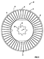
二枚の回転子12は、内側切り抜き部30(図3参照)にある歯を介して、駆動スピンドル28(例えばペダルスピンドル28)に回転可能に固定される。すなわち、回転子は駆動スピンドル28にトルクを伝達することができる。回転子12は両方とも、自身のトルクを共通の駆動スピンドル28に伝達する。両方の回転子12は、共通の回転軸13の周りに同様に回転する駆動スピンドル28とともに回転する。
The two
固定子円盤11も、同様に内側切り抜き部31を有する。内側切り抜き部31には歯が付けられておらず、回転子円盤12の内側切り抜き部30よりもわずかに大きな直径を有する。このため、固定子円盤11は、内側切り抜き部31を通過する駆動スピンドル28に動作可能に接続されるのではなく、駆動スピンドル28の周りにある。すなわち、駆動スピンドル28は固定子円盤11に対して回転する。駆動スピンドル28を固定子円盤11に対して回転可能とする任意の他の望ましい構成、例えばボールベアリングを設けてもよい。
The stator disk 11 similarly has an
固定子円盤11に面している二枚の回転子12の端面15は、軸方向に極性を持つ複数の永久磁石16を有している。この永久磁石は、回転軸13の周りにリング状に配置される(図3参照)。N極およびS極が接線方向に交互に固定子11に面している。
The end faces 15 of the two
図2は、回転子円盤12の基本構造35の切り欠き部32内に永久磁石16が挿入された様子を示す。この結果、固定子11に面している永久磁石16の表面が、回転子円盤12の残りの部分とともに平坦な端面15を形成する。固定子11とは逆の永久磁石16の後側には、切り欠き部32内に磁気帰還路積層部(magnetic return path lamination)33が配置されている。磁気帰還路積層部33は、全ての永久磁石16の後側で連続的に、回転軸13の周りを周方向にリング状に延在している。永久磁石16および場合によって磁気帰還路積層部33がその中に挿入される回転子円盤12の基本構造35は、ポリマー体であってもよい。
FIG. 2 shows a state in which the
固定子11は多数のコイル要素17を有する。コイル要素17は、回転子12の回転軸13の周りにリング状に互いに間隔を空けて配置されている(図5参照)。コイル要素17は、それぞれのコイル軸、すなわちコイル巻線を通る中心線が、回転子12の回転軸13の周りに接線方向に並ぶように配置される。したがって、リング状に配置されたコイル要素17の全てのコイル軸が、回転子12の回転軸13の周りで円の接線となっている。コイル要素17は、例えばポリマー体であってもよい固定子円盤11の基本構造36内に配置される。コイル要素17のうちコイルワイヤ20で構成される巻線は、ポリマー37を用いたポッティングによって封止される。この結果、固定子円盤の内部に巻線が埋め込まれる。コイル要素17間の隔たりがこのポリマーポッティング37内に埋め込まれてもよい。
The stator 11 has a large number of
個々のコイル要素17が図4に示されている。コイル要素は巻型18を有する。この巻型は、周囲にコイルワイヤ20が巻かれたコイルコア19を含む。コイルコア19は平坦な本体を持ち、回転子12の回転軸13(図4には示さず。コイル要素の配置は図5に示されている)に関する径方向および接線方向の長さは、軸方向長さの二倍を超える。言い換えると、コイルコア19は、平坦なストリップ状の材料からなる。コイルコア19は固定子円盤11の軸中心に配置され、軸と平行に並べられる。
図4はさらに、コイルコア19が、コイル軸に沿って両側に互いに逆向きの二つの磁極体21を有する様子を示す。コイル軸はコイルコア19を通って延び、コイルワイヤ20からなる巻線の中心に正確に位置する。磁極体21は、回転子12の回転軸13(図4には示さず。コイル要素の配置は図5に示されている)に関して軸方向および径方向に、コイルコア19の両側を越えて延びる。言い換えると、コイル要素17の磁極体21は両方とも、コイル軸と直交する平面内で全ての側面においてコイルコアを越えて突き出している。したがって、コイルワイヤ20がコイルコア19から滑り出ることはできない。
FIG. 4 further shows that the coil core 19 has two magnetic pole bodies 21 opposite to each other on both sides along the coil axis. The coil axis extends through the coil core 19 and is precisely located at the center of the winding consisting of the
さらに、図4および図5には、各コイル要素17の二つの磁極体21が磁極表面23を形成する様子が示されている。磁極表面23は、互いに逆向きであり回転子12に面している固定子11の両端面22において、それぞれの回転子12の永久磁石16の向かい側に位置している。磁極表面23は、固定子円盤11の残りの部分とともに、平坦な端面22を形成する。磁極体21は、固定子円盤11の全体を通り、向かい合う磁極表面23の間で回転子12の回転軸13に関して軸方向に延びる。
Further, FIGS. 4 and 5 show how two magnetic pole bodies 21 of each
図4からさらに分かるように、磁極表面23は、磁極体21の拡大部24の上に形成される。拡大部は、回転子12の回転軸13に関して接線方向に位置する。この拡大部24は、同じコイル要素17のそれぞれ他方の磁極体21の方向に形成される。すなわち、拡大部24は、コイルワイヤ20を含む巻線の少なくとも一部を越えて延びる。
As can be further understood from FIG. 4, the
図5は、回転子12の回転軸13に関して径方向に磁極体21が並べられた様子を示す。このため、コイル要素17の二つの磁極体21の間の距離、すなわちコイル要素17の接線方向の長さは、回転子12の回転軸13からの径方向距離の増加とともに増加する。これは図4からも明らかである。
FIG. 5 shows a state in which the magnetic pole bodies 21 are arranged in the radial direction with respect to the
回転子12が駆動されて固定子11に対して回転する程度まで、生成される磁界が磁極体21の磁極表面23を介して回転子12の永久磁石16と相互作用するように、固定子11の個々のコイル要素17が電気的に駆動される。
To the extent that the
巻型18は、完全にまたは部分的に磁性ポリマーまたは磁性金属で構成されていてもよい。 The former 18 may be composed entirely or partially of a magnetic polymer or magnetic metal.
インサートを有する射出成形プロセスで回転子と固定子が製造されるように、回転子12および固定子11の製造が行われてもよい。すなわち、コイル要素17または永久磁石16と、場合により別の部品(例えば磁気帰還路積層部33)とが、射出成形機のそれぞれの型穴の中に配置される。続いて、ポリマーが注入される。固化の後、固定子円盤11または回転子円盤12の中の所望の位置にそれぞれの部品が埋め込まれる。
Manufacture of the
図6は、電動自転車25またはペデレック25の駆動部の一例の模式図である。駆動部は、本発明に係る円盤電機子モータ10を有する。円盤電機子モータは、電動自転車25またはペデレック25のペダルスピンドル28上の、ボトムブラケット26とチェーンリング27との間に配置される。電動自転車25またはペデレック25のフレーム34がボトムブラケット26に隣接するか、またはボトムブラケットハウジングがフレーム34の一部である。図示の例示的な実施形態は、上述したチェーンリング27に加えて、二つの別のチェーンリングを有する。
FIG. 6 is a schematic diagram of an example of a drive unit of the
円盤電機子モータ10の径方向の寸法がチェーンリング27の径方向の寸法に一致すること、および、円盤電機子モータ10の軸方向の寸法が、三つのチェーンリングを有するチェーンリングユニットの軸方向長さとほぼ一致することが、はっきりと分かる。したがって、電動自転車25またはペデレック25の観察者からは円盤電機子モータ10をほとんど見ることができず、円盤電機子モータ10のために自転車の魅力が損なわれたり動作が不格好になったりすることはない。
The radial dimension of the
図6は、伝達ねじ(transmission thread)を用いずに、具体的には固定接続または歯を用いた接続によって直接、回転子(単数または複数)12がペダルスピンドル28にトルクを伝達できるように、円盤電機子モータ10の回転子(単数または複数)12がペダルスピンドル28に接続される様子を示す。円盤電機子モータ10は、ハウジングなしで図1ないし5に示した円盤電機子モータ10であってもよい。
FIG. 6 shows that the rotor (s) 12 can transmit torque to the
10 円盤電機子モータ
11 固定子、固定子円盤
12 回転子、回転子円盤
13 回転軸
14 ギャップ
15 回転子内側
16 永久磁石
17 コイル要素
18 巻型
19 コイルコア
20 コイルワイヤ
21 磁極体
22 固定子端面
23 磁極表面
24 拡大部
25 電動自転車、ペデレック
26 ボトムブランケット
27 チェーンリング
28 駆動スピンドル、ペダルスピンドル
29 歯
30 回転子円盤12の内側切り抜き部
31 固定子円盤11の内側切り抜き部
32 回転子円盤12の切り欠き部
33 磁気帰還路積層部
34 フレーム
35 回転子円盤12の基本構造
36 固定子円盤11の基本構造
37 ポリマーポッティング
DESCRIPTION OF
Claims (8)
円盤形の少なくとも一つの固定子(11)と、
前記固定子(11)および/またはモータハウジングに対して回転軸(13)の周りに回転可能に取り付けられる、電機子円盤形の少なくとも一つの回転子(12)と、を備え、
前記回転子(12)および前記固定子(11)は、互いに対して平行にギャップ(14)を空けて配置され、
前記固定子(11)に面する側の前記回転子(12)の端面(15)は、軸方向に極性を有する複数の永久磁石(16)を有し、前記回転軸(13)の周りにリング状に永久磁石が配置され、N極およびS極が接線方向で交互に前記固定子(11)の方を向き、前記固定子(11)は、前記回転子(12)の回転軸(13)の周りにリング状に配置された複数のコイル要素(17)を有し、
共通の回転軸(13)の周りに回転可能に取り付けられた二つの回転子(12)の間に少なくとも一つの固定子(11)が配置され、
前記固定子(11)の前記コイル要素(17)は、それぞれのコイル軸が前記共通の回転軸(13)の周りに接線方向に並ぶように配置され、
前記コイル要素(17)はそれぞれ、周りにコイルワイヤ(20)が巻かれたコイルコア(19)を有する巻型(18)を有し、
前記コイルコア(19)は、前記コイル軸に沿った両側に二つの磁極体(21)を有し、該磁極体は、前記回転子(12)の回転軸(13)に関して軸方向および/または径方向に前記コイルコア(19)の両側を越えて延び、
各コイル要素(17)の両方の磁極体(21)がそれぞれ、前記回転子(12)に面する前記固定子(11)の両端面上で、それぞれの回転子(12)の永久磁石(16)と少なくとも部分的に向かい合う磁極表面(23)を形成し、
前記回転子(12)の回転軸(13)に関して径方向に前記磁極体(21)が並べられ、前記回転子(12)の回転軸(13)からの径方向距離の増加とともに、前記コイル要素(17)の二つの磁極体(21)の間の距離が増加し、
前記コイルコア(19)が平坦な本体であり、前記回転子(12)の回転軸(13)に関する径方向の長さが、自身の軸方向の長さの二倍を超える
ことを特徴とする円盤電機子モータ(10)。 A disc armature motor (10) for an electric bicycle (25) or a pedelec (25),
At least one stator (11) in the form of a disk;
At least one rotor (12) in the form of an armature disk, which is rotatably mounted around the rotation axis (13) with respect to the stator (11) and / or the motor housing,
The rotor (12) and the stator (11) are arranged parallel to each other with a gap (14),
The end surface (15) of the rotor (12) on the side facing the stator (11) has a plurality of permanent magnets (16) having polarity in the axial direction, and around the rotation shaft (13). A permanent magnet is arranged in a ring shape, and the N pole and the S pole are alternately directed in the tangential direction toward the stator (11), and the stator (11) is a rotating shaft (13) of the rotor (12). A plurality of coil elements (17) arranged in a ring around
At least one stator (11) is arranged between two rotors (12) rotatably mounted around a common axis of rotation (13);
The coil elements (17) of the stator (11) are arranged such that the respective coil axes are arranged tangentially around the common rotation axis (13),
The coil elements (17) each have a winding form (18) having a coil core (19) around which a coil wire (20) is wound,
The coil core (19), said has on both sides along the coil axis two of the magnetic pole bodies (21), said magnetic pole body, the axial and / or radial with respect to the rotation axis (13) of said rotor (12) Extending beyond both sides of the coil core (19) in the direction,
Both the magnetic pole bodies (21) of each coil element (17) are on both end faces of the stator (11) facing the rotor (12), and the permanent magnets (16) of the respective rotor (12). ) At least partially opposite the pole surface (23),
The magnetic pole bodies (21) are arranged in the radial direction with respect to the rotation axis (13) of the rotor (12), and the coil element is increased as the radial distance from the rotation axis (13) of the rotor (12) increases. The distance between the two pole bodies (21) of (17) increases,
The disk core, wherein the coil core (19) is a flat main body, and the radial length of the rotor (12) with respect to the rotation axis (13) exceeds twice the axial length of the disk (19). Armature motor (10).
前記円盤電機子モータ(10)は、前記電動自転車(25)またはペデレック(25)のペダルスピンドル(28)上の、ボトムブラケット(26)とチェーンリング(27)との間に配置され、前記回転子(12)が前記ペダルスピンドル(28)にトルクを伝達できるように、前記回転子(12)が前記ペダルスピンドル(28)に接続されることを特徴とする電動自転車(25)またはペデレック(25)。 An electric bicycle (25) or pedelec (25) comprising the disk armature motor (10) according to any one of claims 1 to 6 ,
The disc armature motor (10) is disposed between a bottom bracket (26) and a chain ring (27) on a pedal spindle (28) of the electric bicycle (25) or pedelec (25), and the rotor The electric bicycle (25) or pedelec (25), wherein the rotor (12) is connected to the pedal spindle (28) so that the torque can be transmitted to the pedal spindle (28). .
Applications Claiming Priority (3)
| Application Number | Priority Date | Filing Date | Title |
|---|---|---|---|
| DE102010060482.8 | 2010-11-10 | ||
| DE102010060482.8A DE102010060482B4 (en) | 2010-11-10 | 2010-11-10 | Electric pancake motor and electric bicycle or pedelec with a pancake motor |
| PCT/EP2011/069560 WO2012062710A2 (en) | 2010-11-10 | 2011-11-07 | Electric disk rotor motor and electric bicycle or pedelec comprising a disk rotor motor |
Publications (2)
| Publication Number | Publication Date |
|---|---|
| JP2013546294A JP2013546294A (en) | 2013-12-26 |
| JP5848357B2 true JP5848357B2 (en) | 2016-01-27 |
Family
ID=44971008
Family Applications (1)
| Application Number | Title | Priority Date | Filing Date |
|---|---|---|---|
| JP2013538149A Expired - Fee Related JP5848357B2 (en) | 2010-11-10 | 2011-11-07 | Disc rotor electric motor and electric bicycle or pedelec with disc rotor motor |
Country Status (8)
| Country | Link |
|---|---|
| US (1) | US9438092B2 (en) |
| EP (1) | EP2638618B1 (en) |
| JP (1) | JP5848357B2 (en) |
| KR (1) | KR20140005169A (en) |
| DE (1) | DE102010060482B4 (en) |
| DK (1) | DK2638618T3 (en) |
| ES (1) | ES2533178T3 (en) |
| WO (1) | WO2012062710A2 (en) |
Families Citing this family (20)
| Publication number | Priority date | Publication date | Assignee | Title |
|---|---|---|---|---|
| JP5387400B2 (en) * | 2009-12-28 | 2014-01-15 | 日立工機株式会社 | Electric mower |
| TWI424938B (en) * | 2011-08-23 | 2014-02-01 | Ind Tech Res Inst | Motor assisted rotating eel mechanism |
| DE102012105657A1 (en) * | 2012-06-28 | 2014-01-02 | Horst Walter | Electrical propelled bicycle, has electromotor for driving wheel that comprises disk shaped stator and disk shaped rotor with permanent magnets, where stator is rotated at frame part of bicycle |
| US9718514B2 (en) | 2012-07-11 | 2017-08-01 | Panasonic Intellectual Property Management Co., Ltd. | Electrically assisted bicycle |
| EP2711288A1 (en) | 2012-09-21 | 2014-03-26 | Nikolaus Michels | Wheel drive with electrical motor assist for light vehicles |
| US20140175934A1 (en) * | 2012-12-24 | 2014-06-26 | Korea Electronics Technology Institute | Brushless dc motor of axial gap type |
| DE102013206593A1 (en) * | 2013-04-12 | 2014-10-30 | Siemens Aktiengesellschaft | Flow-type machine in lightweight design |
| US9413198B2 (en) * | 2014-05-06 | 2016-08-09 | Fred W. Etcheverry | Synchronous machine having a flux exciter remote from the rotor |
| DE102014110427A1 (en) * | 2014-07-24 | 2016-01-28 | Pendix Gmbh | Electric bicycle auxiliary drive |
| WO2016034570A1 (en) | 2014-09-02 | 2016-03-10 | Höganäs Ab (Publ) | Stator assembly for an axial flux machine |
| DE102015208277A1 (en) | 2015-05-05 | 2016-11-10 | Robert Bosch Gmbh | Electric machine with rotor cooled over a forest of carbon nanotubes |
| WO2017222359A1 (en) * | 2016-06-24 | 2017-12-28 | Maldonado Bernal Sandro Israel | Electric generator |
| DE102016011591A1 (en) | 2016-09-26 | 2018-03-29 | Wolfgang Meinhard | Device for current-independent driving performance increase during operation of a bicycle. |
| CN108288926A (en) * | 2018-03-30 | 2018-07-17 | 张冰青 | Magnetic suspension motor |
| DE102019000724A1 (en) | 2019-01-30 | 2020-07-30 | Edna Evangelista Marques da Silva | Design, construction, applications and control processes of electrical machines, use of electrically excited secondary parts in linear motors, levitation, magnetic bearings and construction of direct electrical machines |
| CN110611381B (en) * | 2019-09-27 | 2020-10-30 | 南京理工大学 | Drum-type distributed winding axial hybrid excitation motor |
| US20220329138A1 (en) * | 2021-04-07 | 2022-10-13 | Nathaniel Brandon Haines | Induction generator |
| DE102021002106A1 (en) | 2021-04-21 | 2022-10-27 | Edna Evangelista Marques da Silva | Design and construction of rotary electric direct machines with disk rotor and electric direct machines in the form of circular segments to increase the power density |
| CN113300515B (en) * | 2021-06-11 | 2022-11-15 | 山东大学 | Disc type axial magnetic field permanent magnet brushless motor structure containing tangential magnet structure and method thereof |
| CN113991957B (en) * | 2021-11-17 | 2022-12-06 | 长沙理工大学 | Single-phase double-magnetic-circuit permanent magnet motor and driving method |
Family Cites Families (40)
| Publication number | Priority date | Publication date | Assignee | Title |
|---|---|---|---|---|
| US3002399A (en) | 1957-07-23 | 1961-10-03 | Ruess Leopold | Motor with drive for vehicles with pedals, especially two-wheeled vehicles |
| DE3142913A1 (en) * | 1981-10-29 | 1983-05-11 | Herbert Prof. Dr.-Ing. 3300 Braunschweig Weh | Electrical machine having an annular winding armature and permanently excited rotors |
| JPS5956835A (en) * | 1982-09-24 | 1984-04-02 | Matsushita Electric Ind Co Ltd | Motor |
| US4761590A (en) * | 1987-07-20 | 1988-08-02 | Polestar Magnetronics Inc. | Electric motor |
| US5216339A (en) * | 1991-09-30 | 1993-06-01 | Dmytro Skybyk | Lateral electric motor |
| JP2967391B2 (en) | 1994-05-18 | 1999-10-25 | 本田技研工業株式会社 | Treading force detection device for bicycle with assist motor |
| AUPM827094A0 (en) * | 1994-09-20 | 1994-10-13 | Queensland Railways | Open stator axial flux electric motor |
| DE19522419A1 (en) * | 1995-06-21 | 1997-01-02 | Dietrich Gerhard Ellsaeser | Bicycle with auxiliary electric drive |
| JPH0920280A (en) * | 1995-07-06 | 1997-01-21 | Matsushita Electric Ind Co Ltd | Motorized bicycle |
| GB2312403B (en) | 1996-04-26 | 1998-03-25 | Giant Mfg Co | Bicycle equipped with electrical driving device |
| US6531799B1 (en) * | 1999-12-20 | 2003-03-11 | Ford Global Technologies, Inc. | Hybrid electric machine with two rotors, permanent magnet poles and controllable field current |
| DE10028936A1 (en) | 2000-06-16 | 2001-12-20 | Trimerics Gmbh | Electronically commutated electric motor e.g. for axial fan, has two part stator composed of outer and inner ring segments with inner ring provided with slots to accommodate stator coils |
| US6940200B2 (en) | 2000-07-21 | 2005-09-06 | Rotys Inc. | Electric drive |
| JP2002315279A (en) * | 2001-04-18 | 2002-10-25 | Mitsubishi Electric Corp | Rotor of synchronous motor, and method of manufacturing the rotor of the synchronous motor, and synchronous motor and motor for blower and air conditioner |
| US6891306B1 (en) * | 2002-04-30 | 2005-05-10 | Wavecrest Laboratories, Llc. | Rotary electric motor having both radial and axial air gap flux paths between stator and rotor segments |
| WO2004017497A1 (en) * | 2002-07-26 | 2004-02-26 | W.B.T.-S.A. World Business Technology | Generator for use in wind turbines or water-powered wheels |
| EP2043228A3 (en) * | 2002-08-16 | 2014-03-19 | Yamaha Hatsudoki Kabushiki Kaisha | Axial gap type motor generator |
| WO2004073143A1 (en) * | 2003-02-11 | 2004-08-26 | Randall Family Trust | Electric machine having an axial air gap |
| JP2006067650A (en) * | 2004-08-25 | 2006-03-09 | Fujitsu General Ltd | Axial gap motor |
| US7514833B2 (en) * | 2004-09-03 | 2009-04-07 | Ut-Battelle Llc | Axial gap permanent-magnet machine with reluctance poles and PM element covers |
| US7273123B2 (en) | 2004-11-02 | 2007-09-25 | Te-Yu Perng | Electric bicycle power structure |
| JP2006254619A (en) * | 2005-03-11 | 2006-09-21 | Daikin Ind Ltd | Core, armature, motor, and compressor, and manufacturing method thereof |
| JP2006320187A (en) * | 2005-04-14 | 2006-11-24 | Mitsubishi Electric Corp | Toroidal wound motor |
| JP4692090B2 (en) | 2005-06-16 | 2011-06-01 | 株式会社富士通ゼネラル | Axial air gap type electric motor |
| JP4712465B2 (en) * | 2005-07-20 | 2011-06-29 | ヤマハ発動機株式会社 | Rotating electric machine and electric wheelchair |
| CN100483899C (en) * | 2006-01-16 | 2009-04-29 | 联塑(杭州)机械有限公司 | Magnetic rotary device |
| JP4834433B2 (en) * | 2006-03-15 | 2011-12-14 | 株式会社富士通ゼネラル | Manufacturing method of stator core for axial air gap type motor |
| US7554241B2 (en) * | 2006-03-31 | 2009-06-30 | Rao Dantam K | Three-gapped motor with outer rotor and stationary shaft |
| CN2905648Y (en) | 2006-05-09 | 2007-05-30 | 丁富娣 | Driving mechanism for electric bicycle |
| DE102007004359A1 (en) | 2007-01-29 | 2008-07-31 | Ortloff, Helene | Device for controlling direct current motor, has coil elements, which are arranged partially in star-connection with different windings and has neutral point, where windings and neutral point are connected to a computer unit |
| JP2008259399A (en) * | 2007-03-15 | 2008-10-23 | Honda Motor Co Ltd | Stator for rotary electric machine equipped with toroidal winding structure |
| US7755244B2 (en) * | 2007-05-11 | 2010-07-13 | Uqm Technologies, Inc. | Stator for permanent magnet electric motor using soft magnetic composites |
| US20100263959A1 (en) | 2007-07-18 | 2010-10-21 | Rudolf Hoebel | External-rotor electric motor with or without a planetary gear mechanism, motor vehicle with an external-rotor electric motor and a method for operating such a vehicle |
| FR2926935B1 (en) * | 2008-01-30 | 2012-06-08 | Tecddis | AXIAL FLUX AND PERMANENT MAGNET ELECTRIC MACHINE |
| JP2009254109A (en) * | 2008-04-04 | 2009-10-29 | Kobe Steel Ltd | Stator and method of manufacturing the sator |
| DE102009032389A1 (en) | 2008-07-08 | 2010-01-14 | Ortloff, Helene | Plastic motor e.g. micro-motor, has plastic stator and rotor, which together form construction unit without iron, where unit is alternatively operated without sensors with commutation or with sensors and for precision positioning |
| JP2010041885A (en) * | 2008-08-07 | 2010-02-18 | Fujitsu General Ltd | Electromotive driving device and axial air gap type motor |
| US7766114B2 (en) * | 2008-09-04 | 2010-08-03 | Sen-Yung Lee | Driving mechanism for the motorized bicycle |
| IT1392358B1 (en) * | 2008-12-19 | 2012-02-28 | Lucchi | STATIC PART OF AXIAL FLOW ELECTRIC MACHINE EQUIPPED WITH QUARRIES AND PROCEDURE FOR THE REALIZATION OF A SECONDARY STATE OF ELECTRICAL FLOW MACHINE EQUIPPED WITH CAVES. |
| JP2012050271A (en) * | 2010-08-27 | 2012-03-08 | Jtekt Corp | Axial gap type motor |
-
2010
- 2010-11-10 DE DE102010060482.8A patent/DE102010060482B4/en not_active Expired - Fee Related
-
2011
- 2011-11-07 ES ES11782408.6T patent/ES2533178T3/en active Active
- 2011-11-07 JP JP2013538149A patent/JP5848357B2/en not_active Expired - Fee Related
- 2011-11-07 US US13/883,421 patent/US9438092B2/en active Active
- 2011-11-07 EP EP11782408.6A patent/EP2638618B1/en not_active Not-in-force
- 2011-11-07 WO PCT/EP2011/069560 patent/WO2012062710A2/en active Application Filing
- 2011-11-07 DK DK11782408.6T patent/DK2638618T3/en active
- 2011-11-07 KR KR1020137014617A patent/KR20140005169A/en active IP Right Grant
Also Published As
| Publication number | Publication date |
|---|---|
| EP2638618A2 (en) | 2013-09-18 |
| JP2013546294A (en) | 2013-12-26 |
| US20130277131A1 (en) | 2013-10-24 |
| DK2638618T3 (en) | 2015-03-30 |
| EP2638618B1 (en) | 2014-12-17 |
| US9438092B2 (en) | 2016-09-06 |
| DE102010060482B4 (en) | 2017-07-13 |
| KR20140005169A (en) | 2014-01-14 |
| DE102010060482A1 (en) | 2012-05-10 |
| WO2012062710A2 (en) | 2012-05-18 |
| WO2012062710A3 (en) | 2012-12-20 |
| ES2533178T3 (en) | 2015-04-08 |
Similar Documents
| Publication | Publication Date | Title |
|---|---|---|
| JP5848357B2 (en) | Disc rotor electric motor and electric bicycle or pedelec with disc rotor motor | |
| KR101654392B1 (en) | Electric machine - modular | |
| JP4882211B2 (en) | Axial gap motor structure | |
| US9071118B2 (en) | Axial motor | |
| JP2000253635A (en) | Axial gap motor | |
| US20090278415A1 (en) | Coreless motor having rotors arranged concentrically and driving apparatus having the motor | |
| JP2008271640A (en) | Axial gap motor | |
| JP6214990B2 (en) | Rotating electric machine | |
| JP6002020B2 (en) | Rotating electric machine | |
| JP2010183648A (en) | Permanent magnet rotary electric machine and electric vehicle using the same | |
| JP6740865B2 (en) | Brushless motor | |
| JP2004015998A (en) | Permanent magnet version rotating machine with three-phase stator winding divided in axial direction | |
| JP6408766B2 (en) | Axial three-dimensional gap type rotating electric machine | |
| KR101301381B1 (en) | Switched Reluctance Motor | |
| JP7193422B2 (en) | Rotating electric machine and manufacturing method of rotating electric machine | |
| JP2014073011A (en) | Stator for rotary electric machine and rotary electric machine | |
| JP2005130685A (en) | Permanent magnet electric motor with annular stator coil | |
| JP5940354B2 (en) | Electric power steering system motor rotor and electric power steering system motor | |
| JP7006103B2 (en) | Rotor and motor | |
| KR100468983B1 (en) | Axial flux permanent magnet machines | |
| TW201519572A (en) | Dual-rotor motor for bicycle | |
| JP5126585B2 (en) | Axial gap type motor | |
| TWI782545B (en) | Electric mechanical structure and stator shell thereof | |
| KR200230732Y1 (en) | Axial Flux Brushless DC Motor for Electric Vehicles | |
| JP6519676B2 (en) | Vehicle brushless motor |
Legal Events
| Date | Code | Title | Description |
|---|---|---|---|
| A621 | Written request for application examination |
Free format text: JAPANESE INTERMEDIATE CODE: A621 Effective date: 20140814 |
|
| A711 | Notification of change in applicant |
Free format text: JAPANESE INTERMEDIATE CODE: A711 Effective date: 20140918 |
|
| A521 | Written amendment |
Free format text: JAPANESE INTERMEDIATE CODE: A821 Effective date: 20140918 |
|
| A977 | Report on retrieval |
Free format text: JAPANESE INTERMEDIATE CODE: A971007 Effective date: 20150630 |
|
| A131 | Notification of reasons for refusal |
Free format text: JAPANESE INTERMEDIATE CODE: A131 Effective date: 20150804 |
|
| A521 | Written amendment |
Free format text: JAPANESE INTERMEDIATE CODE: A523 Effective date: 20151019 |
|
| TRDD | Decision of grant or rejection written | ||
| A01 | Written decision to grant a patent or to grant a registration (utility model) |
Free format text: JAPANESE INTERMEDIATE CODE: A01 Effective date: 20151110 |
|
| A61 | First payment of annual fees (during grant procedure) |
Free format text: JAPANESE INTERMEDIATE CODE: A61 Effective date: 20151126 |
|
| R150 | Certificate of patent or registration of utility model |
Ref document number: 5848357 Country of ref document: JP Free format text: JAPANESE INTERMEDIATE CODE: R150 |
|
| LAPS | Cancellation because of no payment of annual fees |