JP5831471B2 - 電子部品用収容部材 - Google Patents
電子部品用収容部材 Download PDFInfo
- Publication number
- JP5831471B2 JP5831471B2 JP2013029000A JP2013029000A JP5831471B2 JP 5831471 B2 JP5831471 B2 JP 5831471B2 JP 2013029000 A JP2013029000 A JP 2013029000A JP 2013029000 A JP2013029000 A JP 2013029000A JP 5831471 B2 JP5831471 B2 JP 5831471B2
- Authority
- JP
- Japan
- Prior art keywords
- groove
- ventilation
- electronic component
- hole
- communication hole
- Prior art date
- Legal status (The legal status is an assumption and is not a legal conclusion. Google has not performed a legal analysis and makes no representation as to the accuracy of the status listed.)
- Active
Links
- 238000009423 ventilation Methods 0.000 claims description 116
- 230000004308 accommodation Effects 0.000 claims description 32
- 238000004891 communication Methods 0.000 claims description 19
- 239000007788 liquid Substances 0.000 claims description 10
- 230000000903 blocking effect Effects 0.000 claims 1
- XLYOFNOQVPJJNP-UHFFFAOYSA-N water Substances O XLYOFNOQVPJJNP-UHFFFAOYSA-N 0.000 description 52
- 238000006243 chemical reaction Methods 0.000 description 11
- 238000007689 inspection Methods 0.000 description 10
- 230000002093 peripheral effect Effects 0.000 description 7
- 230000000694 effects Effects 0.000 description 4
- 239000003921 oil Substances 0.000 description 4
- 239000007769 metal material Substances 0.000 description 3
- 239000011347 resin Substances 0.000 description 3
- 229920005989 resin Polymers 0.000 description 3
- 239000000758 substrate Substances 0.000 description 3
- 229910052782 aluminium Inorganic materials 0.000 description 2
- XAGFODPZIPBFFR-UHFFFAOYSA-N aluminium Chemical compound [Al] XAGFODPZIPBFFR-UHFFFAOYSA-N 0.000 description 2
- 238000010586 diagram Methods 0.000 description 2
- 239000000446 fuel Substances 0.000 description 2
- 230000005484 gravity Effects 0.000 description 2
- 238000002347 injection Methods 0.000 description 2
- 239000007924 injection Substances 0.000 description 2
- 238000004519 manufacturing process Methods 0.000 description 2
- 238000000034 method Methods 0.000 description 2
- 239000000853 adhesive Substances 0.000 description 1
- 230000001070 adhesive effect Effects 0.000 description 1
- 239000002313 adhesive film Substances 0.000 description 1
- 239000003990 capacitor Substances 0.000 description 1
- 238000002485 combustion reaction Methods 0.000 description 1
- 238000001816 cooling Methods 0.000 description 1
- 239000000498 cooling water Substances 0.000 description 1
- 230000007423 decrease Effects 0.000 description 1
- 239000010687 lubricating oil Substances 0.000 description 1
- 239000000463 material Substances 0.000 description 1
- 229910052751 metal Inorganic materials 0.000 description 1
- 239000002184 metal Substances 0.000 description 1
- 239000005871 repellent Substances 0.000 description 1
- 238000013022 venting Methods 0.000 description 1
Images


Classifications
-
- F—MECHANICAL ENGINEERING; LIGHTING; HEATING; WEAPONS; BLASTING
- F01—MACHINES OR ENGINES IN GENERAL; ENGINE PLANTS IN GENERAL; STEAM ENGINES
- F01L—CYCLICALLY OPERATING VALVES FOR MACHINES OR ENGINES
- F01L1/00—Valve-gear or valve arrangements, e.g. lift-valve gear
- F01L1/34—Valve-gear or valve arrangements, e.g. lift-valve gear characterised by the provision of means for changing the timing of the valves without changing the duration of opening and without affecting the magnitude of the valve lift
- F01L1/344—Valve-gear or valve arrangements, e.g. lift-valve gear characterised by the provision of means for changing the timing of the valves without changing the duration of opening and without affecting the magnitude of the valve lift changing the angular relationship between crankshaft and camshaft, e.g. using helicoidal gear
- F01L1/352—Valve-gear or valve arrangements, e.g. lift-valve gear characterised by the provision of means for changing the timing of the valves without changing the duration of opening and without affecting the magnitude of the valve lift changing the angular relationship between crankshaft and camshaft, e.g. using helicoidal gear using bevel or epicyclic gear
-
- H—ELECTRICITY
- H05—ELECTRIC TECHNIQUES NOT OTHERWISE PROVIDED FOR
- H05K—PRINTED CIRCUITS; CASINGS OR CONSTRUCTIONAL DETAILS OF ELECTRIC APPARATUS; MANUFACTURE OF ASSEMBLAGES OF ELECTRICAL COMPONENTS
- H05K7/00—Constructional details common to different types of electric apparatus
- H05K7/20—Modifications to facilitate cooling, ventilating, or heating
- H05K7/20845—Modifications to facilitate cooling, ventilating, or heating for automotive electronic casings
-
- F—MECHANICAL ENGINEERING; LIGHTING; HEATING; WEAPONS; BLASTING
- F01—MACHINES OR ENGINES IN GENERAL; ENGINE PLANTS IN GENERAL; STEAM ENGINES
- F01L—CYCLICALLY OPERATING VALVES FOR MACHINES OR ENGINES
- F01L2820/00—Details on specific features characterising valve gear arrangements
- F01L2820/03—Auxiliary actuators
- F01L2820/032—Electric motors
Landscapes
- Engineering & Computer Science (AREA)
- Mechanical Engineering (AREA)
- General Engineering & Computer Science (AREA)
- Physics & Mathematics (AREA)
- Thermal Sciences (AREA)
- Microelectronics & Electronic Packaging (AREA)
- Valve Device For Special Equipments (AREA)
- Casings For Electric Apparatus (AREA)
Description
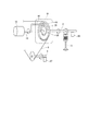
本発明の第1実施形態による「電子部品用収容部材」を用いるバルブタイミング調整装置を図1から図5に示す。
バルブタイミング調整装置1は、「内燃機関」としてのエンジン6に設けられ、「駆動軸」としてのクランク軸8に対する「従動軸」としての吸気側カム軸2の位相(以下、「カム軸位相」という)を所定のカム軸位相に変更する。エンジン6では、カム軸位相の変更によって吸気側カム軸2が開閉駆動する「弁」としての吸気バルブ55(図3参照)の開閉タイミングが変更される。
コネクタ145は、接続部143の径方向外側に設けられる。コネクタ145は、接続部143と一体に形成され、接続部143をベース140に組み込んだとき、ベース140の本体141に形成される切り欠き部に位置する。コネクタ145は、接続部143および回路部142に搭載されている各種電子部品と、外部のECU60や図示しないバッテリ等との電気的接続に用いられる。
モータ軸15の他方の端部152は、ベース140の変換部19側に軸受104と同軸に設けられる軸受105に回転可能に支持される。軸受104、105は、同軸に設けられており、これにより、モータ軸15は、軸受104、105によりケース101およびベース140に正逆回転可能に支持される。
ケース101とベース140との間はシール部材111によりシールされており、第2収容空間100への液体および気体の侵入を防止する。
歯車部材23の周壁部の径方向内側には、遊星回転体50の駆動側外歯車部52と噛み合う駆動側内歯車部24が形成される。
スプロケット25には、周壁部から径方向外側へ突出する歯26を回転方向に複数有している。この歯26とクランク軸8に形成されている複数の歯との間にタイミングベルト9が掛け渡される。これにより、クランク軸8の回転により出力されるトルクがタイミングベルト9を経由してスプロケット25に入力されると、駆動側回転体20は、クランク軸8と連動して回転する。
本体141のカバー部144側は凹状に形成されている。本体141の凹状の部位は、カバー部144のベース140側に形成されている凹状の部位とともに第1収容空間147を形成する。また、本体141の凹状の部位の底面には、貫通孔113が形成されている。貫通孔113は、ベース141の反カバー部144側に設けられるケース101内の第2収容空間100と第1収容空間147とを連通する。
本体141の外縁には、3箇所のねじ止め用貫通孔146が設けられている。
最初に、ベース140の通気部17の第1収容空間147側に通気フィルタ11を取り付ける。通気フィルタ11は、粘着膜を有しており、通気用貫通孔16の内側開口161の縁部に接着される。通気フィルタ11がベース140に接着されたのち、通気用貫通孔16の外側開口162の縁部に検査装置をセットし、1回目の通気検査を実施する。これにより、通気フィルタ11の通気特性を検査する。
このようにして、モータアセンブリ3は完成する。
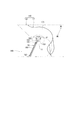
次に、本発明の第2実施形態による「電子部品用収容部材」を用いるバルブタイミング調整装置を図6に基づいて説明する。第2実施形態は、溝部が段差面に接続している点が第1実施形態と異なる。なお、第1実施形態と実質的に同一の部位には同一の符号を付し、説明を省略する。
次に、本発明の第3実施形態による「電子部品用収容部材」を用いるバルブタイミング調整装置を図7に基づいて説明する。第3実施形態は、溝部が凹部に接続している点が第1実施形態と異なる。なお、第1実施形態と実質的に同一の部位には同一の符号を付し、説明を省略する。
次に、本発明の第4実施形態による「電子部品用収容部材」を用いるバルブタイミング調整装置を図8に基づいて説明する。第4実施形態は、通気用貫通孔に連通する溝が複数形成されている点が第1実施形態と異なる。なお、第1実施形態と実質的に同一の部位には同一の符号を付し、説明を省略する。
このように、第4実施形態のバルブタイミング調整装置では、モータアセンブリ3の搭載方向に関係なく、通気フィルタ11上の水膜の水は、複数ある溝のうち地側により近い位置の溝に移動し、通気用貫通孔16から除去される。これにより、第4実施形態のバルブタイミング調整装置は、EDU14の搭載方向に関係なく第1実施形態と同じ効果を奏する。
次に、本発明の第5実施形態による「電子部品用収容部材」を用いるバルブタイミング調整装置を図9に基づいて説明する。第5実施形態は、通気用貫通孔の径外方向の近傍に環状の凹部が形成されている点が第4実施形態と異なる。なお、第4実施形態と実質的に同一の部位には同一の符号を付し、説明を省略する。
(ア)上述の実施形態では、「電子部品用収容部材」は、電動式バルブタイミング調整装置のEDUの回路部および樹脂ケースを収容する収容空間を形成するとした。しかしながら、「電子部品用収容部材」が用いられる装置はこれに限定されない。各種電子部品を収容する収容部材であってもよい。
3 ・・・モータアセンブリ、
10 ・・・モータ、
101 ・・・ケース(収容空間形成部材)、
11 ・・・通気フィルタ(通気部材)、
14 ・・・EDU(モータ通電手段)、
140 ・・・ベース(収容空間形成部材)、
144 ・・・カバー部(収容空間形成部材)、
16 ・・・通気用貫通孔(連通孔)、
161 ・・・内側開口(連通孔の収容空間側の開口)、
19 ・・・変換部、
68 ・・・凹部(第1凹部)、
69 ・・・凹部(第2凹部)。
Claims (8)
- 電子部品(10、142、143)を収容する収容空間(100、147)、および前記収容空間と外部とを連通する連通孔(16)を形成する収容空間形成部材(101、140、144)と、
前記連通孔または前記連通孔の前記収容空間側の開口(161)に設けられ、前記収容空間と外部との間の気体の流れを許容しつつ前記収容空間と外部との間の液体の流れを遮断する通気部材(11)と、
を備え、
前記収容空間形成部材の外壁(149、171)には、前記連通孔の外部側の開口(162)と連通しつつ前記通気部材の外部側表面まで延びるよう形成される第1溝(180)を形成する第1溝部(18)が設けられることを特徴とする電子部品用収容部材。 - 前記第1溝部は、前記通気部材の外部側の表面に接続するよう前記連通孔の外部側から前記収容空間側に傾斜する底面(163)を有することを特徴とする請求項1に記載の電子部品用収容部材。
- 前記第1溝部は、前記連通孔の地側に設けられることを特徴とする請求項1または2に記載の電子部品用収容部材。
- 前記第1溝の体積は、前記連通孔の体積より大きいことを特徴とする請求項1から3のいずれか一項に記載の電子部品用収容部材。
- 前記収容空間形成部材の外壁(149)には、前記第1溝部の前記連通孔に接続する側とは反対側の端部(182)に接続する段差面(172)、または、前記第1溝に連通する第2溝を形成する第2溝部が形成されることを特徴とする請求項1から4のいずれか一項に記載の電子部品用収容部材。
- 前記収容空間形成部材の外壁には、前記第1溝部の前記連通孔に接続する側とは反対側の端部(182)、または、前記第1溝部の前記連通孔に接続する側とは反対側の端部に接続する第2溝部に接続する第1凹部(68)が形成されることを特徴とする請求項1から5のいずれか一項に記載の電子部品用収容部材。
- 前記第1溝は、前記連通孔を中心として放射状に複数形成されることを特徴とする請求項1から6のいずれか一項に記載の電子部品用収容部材。
- 前記収容空間形成部材の外壁には前記連通孔の径外方向に第2凹部(69)が形成され、
前記第2凹部内は、前記第1溝に連通することを特徴とする請求項1から7のいずれか一項に記載の電子部品用収容部材。
Priority Applications (2)
| Application Number | Priority Date | Filing Date | Title |
|---|---|---|---|
| JP2013029000A JP5831471B2 (ja) | 2013-02-18 | 2013-02-18 | 電子部品用収容部材 |
| US13/958,712 US9068481B2 (en) | 2013-02-18 | 2013-08-05 | Electronic component accommodation member and valve timing control device equipped with the same |
Applications Claiming Priority (1)
| Application Number | Priority Date | Filing Date | Title |
|---|---|---|---|
| JP2013029000A JP5831471B2 (ja) | 2013-02-18 | 2013-02-18 | 電子部品用収容部材 |
Related Child Applications (1)
| Application Number | Title | Priority Date | Filing Date |
|---|---|---|---|
| JP2015062611A Division JP6112129B2 (ja) | 2015-03-25 | 2015-03-25 | バルブタイミング調整装置 |
Publications (2)
| Publication Number | Publication Date |
|---|---|
| JP2014157972A JP2014157972A (ja) | 2014-08-28 |
| JP5831471B2 true JP5831471B2 (ja) | 2015-12-09 |
Family
ID=51350231
Family Applications (1)
| Application Number | Title | Priority Date | Filing Date |
|---|---|---|---|
| JP2013029000A Active JP5831471B2 (ja) | 2013-02-18 | 2013-02-18 | 電子部品用収容部材 |
Country Status (2)
| Country | Link |
|---|---|
| US (1) | US9068481B2 (ja) |
| JP (1) | JP5831471B2 (ja) |
Families Citing this family (8)
| Publication number | Priority date | Publication date | Assignee | Title |
|---|---|---|---|---|
| JP6294199B2 (ja) * | 2014-09-25 | 2018-03-14 | アスモ株式会社 | モータ |
| US20180328239A1 (en) * | 2014-12-12 | 2018-11-15 | Hitachi Automotive Systems, Ltd. | Internal-combustion engine valve timing control device |
| US10244644B2 (en) * | 2015-12-04 | 2019-03-26 | Continental Automotive Systems, Inc. | Automotive electronic device having a cover with fins to reduce gel vibration |
| JP6536499B2 (ja) * | 2016-07-01 | 2019-07-03 | 株式会社デンソー | モータ装置 |
| JP6610451B2 (ja) * | 2016-07-01 | 2019-11-27 | 株式会社デンソー | モータ装置 |
| DE112017005600T5 (de) * | 2016-11-07 | 2019-09-12 | Denso Corporation | Anbringungsstruktur für einen Fahrzeugmotor, Ausstattung in einem Fahrzeug, und bürstenloser Motor |
| KR102413791B1 (ko) * | 2017-10-30 | 2022-06-28 | 삼성전자주식회사 | 기판 캐리어 |
| US10483729B1 (en) * | 2019-01-24 | 2019-11-19 | Littelfuse, Inc. | Vented power distribution housing |
Family Cites Families (8)
| Publication number | Priority date | Publication date | Assignee | Title |
|---|---|---|---|---|
| JPH0651013Y2 (ja) | 1988-10-31 | 1994-12-21 | 日本電気株式会社 | 屋外用電子装置の筐体 |
| JPH09172750A (ja) | 1995-10-20 | 1997-06-30 | Mitsubishi Electric Corp | 回転電機の防水構造 |
| JP3921431B2 (ja) | 2002-09-12 | 2007-05-30 | 株式会社日立製作所 | エンジン制御装置 |
| JP3962004B2 (ja) * | 2003-10-27 | 2007-08-22 | 東海興業株式会社 | 樹脂成形防水ケース部材 |
| JP3936327B2 (ja) * | 2003-11-25 | 2007-06-27 | 東海興業株式会社 | 樹脂成形防水ケース部材 |
| JP4560477B2 (ja) | 2005-11-15 | 2010-10-13 | 日立オートモティブシステムズ株式会社 | 電子制御装置および防水ケース |
| JP5147782B2 (ja) * | 2009-05-26 | 2013-02-20 | 古野電気株式会社 | 収容ケース、流動体の流速低下構造、及び、舶用電子機器 |
| JP5016072B2 (ja) * | 2010-02-05 | 2012-09-05 | 三菱電機株式会社 | 防水筐体 |
-
2013
- 2013-02-18 JP JP2013029000A patent/JP5831471B2/ja active Active
- 2013-08-05 US US13/958,712 patent/US9068481B2/en active Active
Also Published As
| Publication number | Publication date |
|---|---|
| JP2014157972A (ja) | 2014-08-28 |
| US9068481B2 (en) | 2015-06-30 |
| US20140230763A1 (en) | 2014-08-21 |
Similar Documents
| Publication | Publication Date | Title |
|---|---|---|
| JP5831471B2 (ja) | 電子部品用収容部材 | |
| US10690134B2 (en) | Drive device | |
| JP6112129B2 (ja) | バルブタイミング調整装置 | |
| JP4600379B2 (ja) | バルブタイミング調整装置 | |
| US8682564B2 (en) | Camshaft position sensing in engines with electric variable cam phasers | |
| JP5946781B2 (ja) | 内燃機関のバルブタイミング制御装置 | |
| US11085507B2 (en) | Control device and associated production method | |
| US9394810B2 (en) | Valve timing controller | |
| KR101209725B1 (ko) | 연속 가변 밸브 타이밍 장치 | |
| JP2010501779A (ja) | 位置センサ一体型可変力ソレノイド | |
| JP2008095552A (ja) | バルブタイミング調整装置 | |
| JP6172877B2 (ja) | 回転電機ユニット | |
| US6789526B2 (en) | Apparatus for controlling throttle valve and manufacturing method for the same and motor | |
| JP5924323B2 (ja) | バルブタイミング調整装置 | |
| US9540964B2 (en) | Variable valve timing camshaft | |
| US20160123197A1 (en) | Valve timing controller | |
| JP5850280B2 (ja) | バルブタイミング調整装置 | |
| JP5645084B2 (ja) | バルブタイミング調整装置 | |
| JP6398855B2 (ja) | バルブ装置の製造方法 | |
| JP6817455B2 (ja) | 内燃機関のバルブタイミング制御装置 | |
| CN109863306A (zh) | 叶片泵 | |
| JP5630489B2 (ja) | バルブタイミング調整装置 | |
| JP2001251814A (ja) | 電気自動車用駆動装置 | |
| JP6840290B2 (ja) | 可変動弁機構及びアクチュエータ | |
| CN108779868A (zh) | 阀装置 |
Legal Events
| Date | Code | Title | Description |
|---|---|---|---|
| A621 | Written request for application examination |
Free format text: JAPANESE INTERMEDIATE CODE: A621 Effective date: 20140612 |
|
| A977 | Report on retrieval |
Free format text: JAPANESE INTERMEDIATE CODE: A971007 Effective date: 20150126 |
|
| A131 | Notification of reasons for refusal |
Free format text: JAPANESE INTERMEDIATE CODE: A131 Effective date: 20150203 |
|
| A521 | Request for written amendment filed |
Free format text: JAPANESE INTERMEDIATE CODE: A523 Effective date: 20150325 |
|
| TRDD | Decision of grant or rejection written | ||
| A01 | Written decision to grant a patent or to grant a registration (utility model) |
Free format text: JAPANESE INTERMEDIATE CODE: A01 Effective date: 20150929 |
|
| A61 | First payment of annual fees (during grant procedure) |
Free format text: JAPANESE INTERMEDIATE CODE: A61 Effective date: 20151012 |
|
| R151 | Written notification of patent or utility model registration |
Ref document number: 5831471 Country of ref document: JP Free format text: JAPANESE INTERMEDIATE CODE: R151 |
|
| R250 | Receipt of annual fees |
Free format text: JAPANESE INTERMEDIATE CODE: R250 |
|
| R250 | Receipt of annual fees |
Free format text: JAPANESE INTERMEDIATE CODE: R250 |
|
| R250 | Receipt of annual fees |
Free format text: JAPANESE INTERMEDIATE CODE: R250 |
|
| R250 | Receipt of annual fees |
Free format text: JAPANESE INTERMEDIATE CODE: R250 |
|
| R250 | Receipt of annual fees |
Free format text: JAPANESE INTERMEDIATE CODE: R250 |
|
| R250 | Receipt of annual fees |
Free format text: JAPANESE INTERMEDIATE CODE: R250 |