JP5789833B2 - Game machine - Google Patents
Game machine Download PDFInfo
- Publication number
- JP5789833B2 JP5789833B2 JP2011145335A JP2011145335A JP5789833B2 JP 5789833 B2 JP5789833 B2 JP 5789833B2 JP 2011145335 A JP2011145335 A JP 2011145335A JP 2011145335 A JP2011145335 A JP 2011145335A JP 5789833 B2 JP5789833 B2 JP 5789833B2
- Authority
- JP
- Japan
- Prior art keywords
- special
- game
- state
- display
- information
- Prior art date
- Legal status (The legal status is an assumption and is not a legal conclusion. Google has not performed a legal analysis and makes no representation as to the accuracy of the status listed.)
- Active
Links
Images


Description
本発明は、表示装置を備え、遊技履歴の表示を行うパチンコやパチスロなどの遊技機に関する。 The present invention relates to a gaming machine such as a pachinko or pachislot machine that includes a display device and displays a game history .
従来、所定条件の成立に基づいて、複数の識別情報が変動する変動ゲームを行い、当該変動ゲームの結果に応じて遊技者に利益を付与する制御を実行可能であり、前記変動ゲームに関連する表示を表示可能な表示装置を備えたパチンコやパチスロなどの遊技機が知られている(例えば特許文献1参照)。
このような遊技機においては、例えば、過去に大当たりが発生した回数などの履歴情報を表示可能なものが知られている。
Conventionally, it is possible to execute a control game in which a plurality of pieces of identification information fluctuate based on the establishment of a predetermined condition, and to give a profit to the player according to the result of the control game, and related to the control game A gaming machine such as a pachinko or pachislot machine equipped with a display device capable of displaying a display is known (see, for example, Patent Document 1).
As such a gaming machine, for example, one that can display history information such as the number of times a big hit has occurred in the past is known.
従来の遊技機では、単に文字情報として現在の遊技機の履歴情報を報知するだけなので、当該遊技機に対する興味を引くものではなかった。 In the conventional gaming machine, since the history information of the current gaming machine is simply notified as character information, it has not attracted interest in the gaming machine.
本発明の目的は、パチンコやパチスロなどの遊技機において、単に文字情報として遊技情報を報知するのではなく、従来にない形態で履歴情報を報知することにより、当該遊技機に対する興味を引くことにある。 It is an object of the present invention to attract interest in a gaming machine such as a pachinko machine or a pachislot machine by notifying game information simply as character information but by reporting history information in an unprecedented form. is there.
以上の課題を解決するため、請求項1に記載の発明は、所定条件の成立に基づいて、複数の識別情報が変動する変動ゲームを行い、当該変動ゲームの結果が特別結果となった場合に遊技者に有利な特別遊技を発生可能であり、前記変動ゲームに関連する表示を表示可能な表示装置を備えた遊技機において、
当該遊技機の遊技に関する複数種類の履歴情報を記憶する履歴情報記憶手段と、
前記履歴情報記憶手段に記憶された履歴情報を報知するための履歴情報報知制御手段と、
前記履歴情報を報知するときの表示態様を複数記憶する履歴情報表示態様記憶手段と、
を備え、
前記履歴情報記憶手段に記憶される複数種類の履歴情報には、前記特別遊技の発生に係る情報が含まれるとともに、当該特別遊技の発生に係る情報には、少なくとも当該特別遊技が発生した順番を含み、
前記履歴情報報知制御手段は、
前記履歴情報記憶手段に記憶された複数種類の履歴情報の内、報知することとなる特定の履歴情報に応じて前記履歴情報表示態様記憶手段に記憶された複数の表示態様の中から特定の表示態様を選択し、選択された当該特定の表示態様で当該特定の履歴情報を前記表示装置に表示して報知するものであり、
前記特定の履歴情報として、前記特別遊技の発生に係る情報を報知し、
報知することとなる前記特別遊技の発生に係る情報の内、当該特別遊技が発生した順番に応じて、前記特定の表示態様を選択することを特徴とする。
In order to solve the above-described problems, the invention according to
History information storage means for storing a plurality of types of history information related to the game of the gaming machine;
History information notification control means for notifying history information stored in the history information storage means;
History information display mode storage means for storing a plurality of display modes when notifying the history information;
With
The plurality of types of history information stored in the history information storage means include information relating to the occurrence of the special game, and the information relating to the occurrence of the special game includes at least the order in which the special game has occurred. Including
The history information notification control means includes
Among a plurality of types of history information stored in the history information storage means, a specific display from among a plurality of display modes stored in the history information display mode storage means according to specific history information to be notified select embodiments, which notifies by displaying the specific history information on the display device at selected has been the particular display mode,
As the specific history information, information related to the occurrence of the special game,
Of the information related to the occurrence of the special game to be notified, the specific display mode is selected according to the order in which the special game is generated .
ここで、「表示態様」とは、例えば、履歴情報を報知する際、表示装置に表示される背景である。
請求項1に記載の発明によれば、報知することとなる特定の履歴情報に応じて前記履歴情報表示態様記憶手段に記憶された複数の表示態様の中から特定の表示態様を選択し、選択された当該特定の表示態様で当該特定の履歴情報を前記表示装置に表示して報知する。
従って、単に文字情報として現在の遊技機の履歴情報を報知するだけでなく、報知する履歴情報に応じて報知態様を変化させることにより、当該遊技機に対する興味を引くことができるようになる。
また、履歴情報として特別遊技の発生に係る情報を報知し、報知することとなる当該情報の内の特別遊技が発生した順番に応じて特定の表示態様を選択するので、特別遊技が発生した順番に応じて報知態様を変化させることにより、当該遊技機に対する興味を引くことができるようになる。
Here, the “display mode” is, for example, the background displayed on the display device when reporting the history information.
According to the first aspect of the present invention, a specific display mode is selected from a plurality of display modes stored in the history information display mode storage unit according to the specific history information to be notified, and is selected . The specific history information is displayed on the display device and notified in the selected specific display mode.
Accordingly, not only the history information of the current gaming machine is notified as text information but also the notification mode is changed in accordance with the history information to be notified, thereby attracting interest in the gaming machine.
In addition, information relating to the occurrence of a special game is reported as history information, and a specific display mode is selected according to the order of occurrence of the special game among the information to be notified, so the order of occurrence of the special game By changing the notification mode according to the situation, it is possible to attract interest in the gaming machine.
請求項2に記載の発明は、所定条件の成立に基づいて、複数の識別情報が変動する変動ゲームを行い、当該変動ゲームの結果が特別結果となった場合に遊技者に有利な特別遊技を発生可能であり、前記変動ゲームに関連する表示を表示可能な表示装置を備えた遊技機において、
当該遊技機の遊技に関する複数種類の履歴情報を記憶する履歴情報記憶手段と、
前記履歴情報記憶手段に記憶された履歴情報を報知するための履歴情報報知制御手段と、
前記履歴情報を報知するときの表示態様を複数記憶する履歴情報表示態様記憶手段と、
を備え、
前記特別遊技の終了後には、当該特別遊技の発生に関連して遊技者に付与される付加遊技価値が発生可能であり、
前記履歴情報報知制御手段は、前記付加遊技価値の発生に関連して前記表示態様を選択することで、同じ履歴情報を報知する際には、発生中の前記付加遊技価値にかかわらず同一の情報を表示するとともに、当該同一の情報を発生中の前記付加遊技価値に応じて異なる表示態様で表示することが可能であることを特徴とする。
The invention according to
History information storage means for storing a plurality of types of history information related to the game of the gaming machine;
History information notification control means for notifying history information stored in the history information storage means;
History information display mode storage means for storing a plurality of display modes when notifying the history information;
With
After the end of the special game, an additional game value given to the player in relation to the occurrence of the special game can be generated,
The history information notification control means selects the display mode in relation to the generation of the additional game value, so that when the same history information is notified , the same information regardless of the additional game value being generated. It displays an, characterized in that in response to the additional game value in generating the same information can be displayed in a manner different.
ここで、「付加遊技価値」とは、例えば、高確率状態や時短状態にすることである。Here, the “additional game value” is, for example, a high probability state or a short time state.
請求項2に記載の発明によれば、付加遊技価値の発生に関連して表示態様を変化させることにより、当該遊技機の興趣を高めることができる。 According to the invention described in
本発明によれば、パチンコやパチスロなどの遊技機において、従来にない形態で履歴情報を報知することができるので、当該遊技機に対する興味を引くことができるようになる。 According to the present invention, in gaming machines such as pachinko and pachislot machines, history information can be notified in an unprecedented form, so that interest in the gaming machine can be attracted.
〔第1実施形態〕
以下、本発明の好適な実施の形態を図面に基づいて説明する。
図1は、本発明の第1実施形態の遊技機の説明図である。
[First Embodiment]
DESCRIPTION OF EXEMPLARY EMBODIMENTS Hereinafter, preferred embodiments of the invention will be described with reference to the drawings.
FIG. 1 is an explanatory diagram of the gaming machine according to the first embodiment of the present invention.
本発明の実施の形態の遊技機10は前面枠12を備え、該前面枠12は本体枠(外枠)11にヒンジ13を介して開閉回動可能に組み付けられている。遊技盤30(図2参照)は前面枠12の表側に形成された収納部(図示省略)に収納されている。また、前面枠(内枠)12には、遊技盤30の前面を覆うカバーガラス(透明部材)14を備えたガラス枠15が取り付けられている。
A
また、ガラス枠15の上部には、ランプ及びモータを内蔵した照明装置(ムービングライト)16や払出異常報知用のランプ(LED)17が設けられている。また、ガラス枠15の左右にはランプ等を内蔵し装飾や演出のための発光をする枠装飾装置18や、音響(例えば、効果音)を発するスピーカ(上スピーカ)19aが設けられている。さらに、前面枠12の下部にもスピーカ(下スピーカ)19bが設けられている。
Further, an illuminating device (moving light) 16 incorporating a lamp and a motor and a lamp (LED) 17 for notifying a dispensing abnormality are provided on the upper part of the
また、前面枠12の下部には、図示しない打球発射装置に遊技球を供給する上皿21、遊技機10の裏面側に設けられている球払出装置から払い出された遊技球が流出する上皿球出口22、上皿21が一杯になった状態で払い出された遊技球を貯留する下皿23及び打球発射装置の操作部24が設けられている。さらに、上皿21の上縁部には、遊技者からの操作入力を受け付けるための操作スイッチを内蔵した演出ボタン25とセレクトボタン29が設けられている。さらに、前面枠12下部右側には、前面枠12を開放したり施錠したりするための鍵26が設けられている。
Further, on the lower part of the
この実施の形態の遊技機10においては、遊技者が上記操作部24を回動操作することによって、打球発射装置が、上皿21から供給される遊技球を遊技盤30前面の遊技領域32に向かって発射する。また、遊技者が演出ボタン25を操作することによって、表示装置41(図2参照)における変動表示ゲーム(飾り特図変動表示ゲーム)において、遊技者の操作を介入させた演出等を行わせることができる。さらに、上皿21上方のガラス枠15の前面には、遊技者が隣接する球貸機から球貸しを受ける場合に操作する球貸ボタン27、球貸機のカードユニットからプリペイドカードを排出させるために操作する排出ボタン28、プリペイドカードの残高を表示する残高表示部(図示省略)等が設けられている。
In the
次に、図2を用いて遊技盤30の一例について説明する。図2は、本発明の実施の形態の遊技盤30の正面図である。
Next, an example of the
遊技盤30の表面には、ガイドレール31で囲われた略円形状の遊技領域32が形成されている。遊技領域32は、遊技盤30の四隅に各々設けられた樹脂製のサイドケース33及びガイドレール31に囲繞されて構成される。遊技領域32には、ほぼ中央に表示装置41を備えたセンターケース40が配置されている。表示装置41は、センターケース40に設けられた凹部に、センターケース40の前面より奥まった位置に取り付けられている。即ち、センターケース40は表示装置41の表示領域の周囲を囲い、表示装置41の表示面よりも前方へ突出するように形成されている。
On the surface of the
表示装置41(変動表示装置)は、例えば、LCD(液晶表示器)、CRT(ブラウン管)等の表示画面を有する装置で構成されている。表示画面の画像を表示可能な領域(表示領域)には、複数の識別情報(特別図柄)や特図変動表示ゲームを演出するキャラクタや演出効果を高める背景画像等が表示される。表示装置41の表示画面においては、識別情報として割り当てられた複数の特別図柄が変動表示(可変表示)されて、特図変動表示ゲームに対応した飾り特図変動表示ゲームが行われる。また、表示画面には遊技の進行に基づく演出のための画像(例えば、大当たり表示画像、ファンファーレ表示画像、エンディング表示画像等)が表示される。
The display device 41 (variable display device) is configured by a device having a display screen such as an LCD (Liquid Crystal Display) or a CRT (CRT). A plurality of pieces of identification information (special symbols), a character that produces a special figure variation display game, a background image that enhances the effect, and the like are displayed in an area (display area) in which an image of the display screen can be displayed. On the display screen of the
遊技領域32のセンターケース40の右下側には、普通図柄始動ゲート(普図始動ゲート)34が設けられている。また、センターケース40の左下側には、三つの一般入賞口35が配置され、センターケース40の右下側には、一つの一般入賞口35が配置されている。
これら一般入賞口35、…には、各一般入賞口35に入った遊技球を検出するための一般入賞口スイッチ35a〜35n(図3参照)が配設されている。
On the lower right side of the
.. Are provided with general winning
また、センターケース40の下方には、特図変動表示ゲームの開始条件を与える第1始動入賞口(始動入賞領域)としての始動入賞口36が設けられ、その直下には上部に逆「ハ」の字状に開いて遊技球が流入し易い状態に変換する一対の可動部材37b、37bを備えるとともに内部に第2始動入賞口(始動入賞領域)を有する普通変動入賞装置(普電)37が配設されている。
Also, below the
普通変動入賞装置37の一対の開閉部材37b,37bは、常時は遊技球の直径程度の間隔をおいた閉じた閉状態(遊技者にとって不利な状態)を保持している。ただし、普通変動入賞装置37の上方には、始動入賞口36が設けられているので、閉じた状態では遊技球が入賞できないようになっている。
そして、普図変動表示ゲームの結果が所定の停止表示態様となった場合には、駆動装置としての普電ソレノイド37c(図3参照)によって、逆「ハ」の字状に開いて普通変動入賞装置37に遊技球が流入し易い開状態(遊技者にとって有利な状態)に変化させられるようになっている。
The pair of opening / closing
When the result of the normal variation display game becomes a predetermined stop display mode, it is opened in a reverse “C” shape by a general
さらに、普図始動ゲート34の下方には、特図変動表示ゲームの結果によって遊技球を受け入れない状態と受け入れ易い状態とに変換可能な特別変動入賞装置(大入賞口)38が配設されている。
Further, a special variable winning device (large winning opening) 38 that can be converted into a state in which a game ball is not accepted or a state in which it is easy to accept depending on the result of the special figure variation display game is disposed below the usual
特別変動入賞装置38は、上端側が手前側に倒れる方向に回動して開放可能になっているアタッカ形式の開閉扉38cを有しており、補助遊技としての特図変動表示ゲームの結果如何によって大入賞口を閉じた状態(遊技者にとって不利な閉塞状態)から開放状態(遊技者にとって有利な状態)に変換する。
即ち、特別変動入賞装置38は、例えば、駆動装置としての大入賞口ソレノイド38b(図3参照)により駆動される開閉扉38cによって開閉される大入賞口を備え、特別遊技状態中は、大入賞口を閉じた状態から開いた状態に変換することにより大入賞口内への遊技球の流入を容易にさせ、遊技者に所定の遊技価値(賞球)を付与するようになっている。
なお、大入賞口の内部(入賞領域)には、当該大入賞口に入った遊技球を検出する検出手段としてのカウントスイッチ38a(図3参照)が配設されている。
特別変動入賞装置38の下方には、入賞口などに入賞しなかった遊技球を回収するアウト口39が設けられている。
The special
That is, the special variable winning
In addition, a
Below the special variable winning
また、遊技領域32の外側(例えば、遊技盤30の右下部)には、特図変動表示ゲームをなす第1特図変動表示ゲームや第2特図変動表示ゲーム及び普図始動ゲート34への入賞をトリガとする普図変動表示ゲームを一箇所で実行する一括表示装置50が設けられている。
In addition, on the outside of the game area 32 (for example, in the lower right part of the game board 30), the first special figure fluctuation display game, the second special figure fluctuation display game, and the general figure start
一括表示装置50は、7セグメント型の表示器(LEDランプ)等で構成された第1特図変動表示ゲーム用の第1特図変動表示部(第1特図表示器)51及び第2特図変動表示ゲーム用の第2特図変動表示部(第2特図表示器)52と、を備える。また、一括表示装置50には、図示は省略するが、普図変動表示ゲーム用の変動表示部(普図表示器)、LEDランプ4つで構成された特図1変動表示ゲームの始動記憶数報知用の特図1保留表示器および特図2変動表示ゲームの始動記憶数報知用の特図2保留表示器、LEDランプ2つで構成された普図変動表示ゲームの始動記憶数報知用の普図保留表示器、大当りが発生すると点灯して大当り発生を報知する第1遊技状態表示器、時短状態が発生すると点灯して時短状態発生を報知する第2遊技状態表示器、遊技機10の電源投入時に大当りの確率状態が高確率状態となっていることを表示する高確率報知器、大当り時のラウンド数(特別変動入賞装置38の開閉回数)を表示するラウンド数表示器が設けられている。
The
第1特図表示器51と第2特図表示器52における特図変動表示ゲームは、例えば変動表示ゲームの実行中、即ち、表示装置41において飾り特図変動表示ゲームを行っている間は、中央のセグメントを点滅駆動させて変動中であることを表示する。そして、ゲームの結果が「はずれ」のときは、はずれの結果態様として例えば中央のセグメントを点灯状態にし、ゲームの結果が「大当り」のときは、当りの結果態様(特別結果態様)としてはずれの結果態様以外の結果態様(例えば「3」や「7」の数字等)を点灯状態にしてゲーム結果を表示する。
The special figure fluctuation display game in the first
本発明の実施の形態の遊技機10では、打球発射装置から遊技領域32に向けて遊技球(パチンコ球)が打ち出されることによって遊技が行われる。打ち出された遊技球は、遊技領域32内の各所に配置された障害釘や風車等の方向転換部材によって転動方向を変えながら遊技領域32を流下し、普図始動ゲート34、一般入賞口35、始動入賞口36、普通変動入賞装置37又は特別変動入賞装置38に入賞するか、遊技領域32の最下部に設けられたアウト口39へ流入し遊技領域から排出される。そして、一般入賞口35、始動入賞口36、普通変動入賞装置37又は特別変動入賞装置38に遊技球が入賞すると、入賞した入賞口の種類に応じた数の賞球が、払出制御装置200によって制御される払出ユニットから、前面枠12の上皿21又は下皿23に排出される。
In the
一方、普図始動ゲート34内には、該普図始動ゲート34を通過した遊技球を検出するための非接触型のスイッチなどからなるゲートスイッチ34a(図3参照)が設けられており、遊技領域32内に打ち込まれた遊技球が普図始動ゲート34内を通過すると、ゲートスイッチ34aにより検出されて普図変動表示ゲームが行われる。
また、普図変動表示ゲームを開始できない状態、例えば、既に普図変動表示ゲームが行われ、その普図変動表示ゲームが終了していない状態や、普図変動表示ゲームが当って普通変動入賞装置37が開状態に変換されている場合に、普図始動ゲート34を遊技球が通過すると、普図始動記憶数の上限数未満でならば、普図始動記憶数が加算(+1)されて普図始動記憶が1つ記憶されることとなる。この普図始動入賞の記憶数は、一括表示装置50の始動入賞数報知用の普図保留表示器(図示省略)に表示される。
また、普図始動記憶には、普図変動表示ゲームの当りはずれを決定するための当り判定用乱数値が記憶されるようになっていて、この当り判定用乱数値が判定値と一致した場合に、当該普図変動表示ゲームが当りとなって特定の結果態様(特定結果)が導出されることとなる。
On the other hand, a
In addition, the normal variation display game cannot be started, for example, the normal variation display game has already been played and the normal variation display game has not been completed, When 37 is converted to the open state and the game ball passes through the general figure start
In addition, in the normal chart start memory, a random number value for hit determination for determining a hit error of the normal figure fluctuation display game is stored, and when the random number value for hit determination coincides with the determination value In addition, a specific result mode (specific result) is derived by hitting the common map fluctuation display game.
普図変動表示ゲームは、一括表示装置50に設けられた変動表示部(普図表示器)(図示省略)で実行されるようになっている。普図表示器は、普通識別情報(普図、普通図柄)として点灯状態の場合に当りを示し、消灯状態の場合にはずれを示すLEDから構成され、このLEDを点滅表示することで普通識別情報の変動表示を行い、所定の変動表示時間の経過後、LEDを点灯又は消灯することで結果を表示するようになっている。
なお、普通識別情報として例えば数字、記号、キャラクタ図柄などを用い、これを所定時間変動表示させた後、停止表示させることにより行うように構成しても良い。この普図変動表示ゲームの停止表示が特定結果となれば、普図の当りとなって、普通変動入賞装置37の一対の可動部材37bが所定時間(例えば、0.3秒間)開放される開状態となる。これにより、普通変動入賞装置37の内部の第2始動入賞口へ遊技球が入賞し易くなり、第2特図変動表示ゲームが実行される回数が多くなる。
The usual map change display game is executed by a change display unit (usual display device) (not shown) provided in the
Note that, for example, numbers, symbols, character designs, and the like may be used as the normal identification information, which is displayed by variably displaying for a predetermined time and then stopped. If the stop display of the usual figure change display game is a specific result, the pair of
普図始動ゲート34への通過検出時に抽出した普図乱数値が当り値であるときには、普図表示器に表示される普通図柄が当り状態で停止し、当り状態となる。このとき、普通変動入賞装置37は、内蔵されている普電ソレノイド37c(図3参照)が駆動されることにより、可動部材37bが所定の時間(例えば、0.3秒間)だけ開放する状態に変換され、遊技球の入賞が許容される。
When the random number value extracted at the time of detection of the passage to the universal figure start
始動入賞口36への入賞球及び普通変動入賞装置37への入賞球は、それぞれは内部に設けられた始動口1スイッチ36aと始動口2スイッチ37aによって検出される。始動入賞口36へ入賞した遊技球は第1特図変動表示ゲームの始動入賞球として検出され、所定の上限数(例えば、4個)を限度に記憶されるとともに、普通変動入賞装置37へ入賞した遊技球は第2特図変動表示ゲームの始動入賞球として検出され、所定の上限数(例えば、4個)を限度に記憶される。
また、この始動入賞球の検出時にそれぞれ大当り乱数値や大当り図柄乱数値、並びに各変動パターン乱数値が抽出され、抽出された乱数値は、遊技制御装置100(図3参照)内の特図記憶領域(RAMの一部)に特図始動記憶として各々所定回数(例えば、最大で4回分)を限度に記憶される。そして、この特図始動記憶の記憶数は、一括表示装置50の始動入賞数報知用の特図1、特図2保留表示器(図示省略)に表示されるとともに、センターケース40の表示装置41においても表示される。
The winning ball to the
In addition, when the starting winning ball is detected, a big hit random number value, a big hit symbol random number value, and each variation pattern random number value are extracted. Each area (a part of the RAM) is stored as a special figure start memory for a predetermined number of times (for example, a maximum of four times). The number stored in the special figure start memory is displayed on the special figure 1 and special figure 2 on-hold display (not shown) for notifying the start winning number of the
遊技制御装置100は、始動入賞口36若しくは普通変動入賞装置37への入賞、又はそれらの始動記憶に基づいて、特図1表示器51又は特図2表示器52で第1又は第2特図変動表示ゲームを行う。
第1特図変動表示ゲーム及び第2特図変動表示ゲームは、複数の特別図柄(特図、識別情報)を変動表示したのち、所定の結果態様を停止表示することで行われる。また、表示装置41にて各特図変動表示ゲームに対応して複数種類の識別情報(例えば、数字、記号、キャラクタ図柄など)を変動表示させる飾り特図変動表示ゲームが実行されるようになっている。
そして、特図変動表示ゲームの結果として、特図1表示器51若しくは特図2表示器52の表示態様が特別結果態様となった場合には、大当りとなって特別遊技状態(いわゆる、大当り状態)となる。また、これに対応して表示装置41の表示態様も特別結果態様となる。
The
The first special figure fluctuation display game and the second special figure fluctuation display game are performed by variably displaying a plurality of special symbols (special figures, identification information) and then stopping and displaying a predetermined result form. In addition, a decorative special figure fluctuation display game for displaying a plurality of types of identification information (for example, numbers, symbols, character designs, etc.) corresponding to each special figure fluctuation display game on the
As a result of the special figure fluctuation display game, when the display mode of the special figure 1
表示装置41における飾り特図変動表示ゲームは、例えば前述した数字等で構成される飾り特別図柄(識別情報)が左(第一特別図柄)、右(第二特別図柄)、中(第三特別図柄)の順に変動表示を開始して、所定時間後に変動している図柄を順次停止させて、特図変動表示ゲームの結果を表示することで行われる。また、表示装置41では、特図始動記憶数に対応する飾り特別図柄による変動表示ゲームを行うとともに、興趣向上のためにキャラクタの出現など多様な演出表示が行われる。
In the decorative special symbol variation display game on the
なお、特図1表示器51、特図2表示器52は、別々の表示器でも良いし同一の表示器でも良いが、各々独立して、また、同時には実行しないように各特図変動表示ゲームが表示される。また、表示装置41も、第1特図変動表示ゲームと第2特図変動表示ゲームで別々の表示装置や別々の表示領域を使用するとしても良いし、同一の表示装置や表示領域を使用するとしても良いが、各々独立して、また、同時には実行しないように飾り特図変動表示ゲームが表示される。また、遊技機10に特図1表示器51、特図2表示器52を備えずに、表示装置41のみで特図変動表示ゲームを実行するようにしても良い。
また、第2特図変動表示ゲームは、第1特図変動表示ゲームよりも優先して実行されるようになっている。即ち、第1特図変動表示ゲームと第2特図変動表示ゲームの始動記憶がある場合であって、特図変動表示ゲームの実行が可能となった場合は、第2特図変動表示ゲームが実行されるようになっている。
The special figure 1
Further, the second special figure variation display game is executed with priority over the first special figure variation display game. That is, if there is a start memory of the first special figure fluctuation display game and the second special figure fluctuation display game, and the execution of the special figure fluctuation display game becomes possible, the second special figure fluctuation display game is It is supposed to be executed.
また、第1特図変動表示ゲーム(第2特図変動表示ゲーム)が開始可能な状態で、且つ、始動記憶数が0の状態で、始動入賞口36(若しくは、普通変動入賞装置37)に遊技球が入賞すると、始動権利の発生に伴って始動記憶が記憶されて、始動記憶数が1加算されるととともに、直ちに始動記憶に基づいて、第1特図変動表示ゲーム(第2特図変動表示ゲーム)が開始され、この際に始動記憶数が1減算される。
一方、第1特図変動表示ゲーム(第2特図変動表示ゲーム)が直ちに開始できない状態、例えば、既に第1若しくは第2特図変動表示ゲームが行われ、その特図変動表示ゲームが終了していない状態や、特別遊技状態となっている場合に、始動入賞口36(若しくは、普通変動入賞装置37)に遊技球が入賞すると、始動記憶数が上限数未満ならば、始動記憶数が1加算されて始動記憶が1つ記憶されることになる。そして、始動記憶数が1以上となった状態で、第1特図変動表示ゲーム(第2特図変動表示ゲーム)が開始可能な状態(前回の特図変動表示ゲームの終了若しくは特別遊技状態の終了)となると、始動記憶数が1減算されるとともに、記憶された始動記憶に基づいて第1特図変動表示ゲーム(第2特図変動表示ゲーム)が開始される。
なお、以下の説明において、第1特図変動表示ゲームと第2特図変動表示ゲームを区別しない場合は、単に特図変動表示ゲームと称する。
In addition, in the state where the first special figure fluctuation display game (second special figure fluctuation display game) can be started and the number of start memories is zero, the start winning opening 36 (or the normal fluctuation prize winning device 37) is entered. When the game ball wins, the start memory is stored as the start right is generated, the start memory number is incremented by 1, and the first special figure variation display game (second special figure) is immediately added based on the start memory. (Variable display game) is started, and at this time, the start memory number is decremented by one.
On the other hand, a state in which the first special figure fluctuation display game (second special figure fluctuation display game) cannot be started immediately, for example, the first or second special figure fluctuation display game has already been performed, and the special figure fluctuation display game has ended. If the game ball is won in the start winning opening 36 (or the normal variable prize winning device 37) in a state that is not in the special game state or in the special game state, the start memory number is 1 if the start memory number is less than the upper limit number. By adding, one start memory is stored. Then, in a state where the starting memory number becomes 1 or more, a state in which the first special figure fluctuation display game (second special figure fluctuation display game) can be started (the end of the previous special figure fluctuation display game or the special game state) (End), the start memory number is decremented by 1, and the first special figure fluctuation display game (second special figure fluctuation display game) is started based on the stored start memory.
In the following description, when the first special figure fluctuation display game and the second special figure fluctuation display game are not distinguished, they are simply referred to as a special figure fluctuation display game.
なお、特に限定されるわけではないが、上記始動入賞口36内の始動口1スイッチ36a、普通変動入賞装置37内の始動口2スイッチ37a、ゲートスイッチ34a、一般入賞口スイッチ35a〜35n、カウントスイッチ38aには、磁気検出用のコイルを備え該コイルに金属が近接すると磁界が変化する現象を利用して遊技球を検出する非接触型の磁気近接センサ(以下、近接スイッチと称する)が使用されている。遊技機10のガラス枠15等に設けられた前枠開放検出スイッチ63や前面枠(遊技枠)12等に設けられた遊技枠開放検出スイッチ64には、機械的な接点を有するマイクロスイッチを用いることができる。
Although not particularly limited, the starting
図3は、本実施形態の遊技機10の制御システムのブロック図である。
遊技機10は遊技制御装置100を備え、遊技制御装置100は、遊技を統括的に制御する主制御装置(主基板)であって、遊技用マイクロコンピュータ(以下、遊技用マイコンと称する)111を有するCPU部110と、入力ポートを有する入力部120と、出力ポートやドライバなどを有する出力部130、CPU部110と入力部120と出力部130との間を接続するデータバス140などからなる。
FIG. 3 is a block diagram of the control system of the
The
上記CPU部110は、アミューズメントチップ(IC)と呼ばれる遊技用マイコン(CPU)111と、入力部120内の近接スイッチ用のインタフェースチップ(近接I/F)121からの信号(始動入賞検出信号)を論理反転して遊技用マイコン111に入力させるインバータなどからなる反転回路112と、水晶振動子のような発振子を備え、CPUの動作クロックやタイマ割込み、乱数生成回路の基準となるクロックを生成する発振回路(水晶発振器)113などを有する。遊技制御装置100及び該遊技制御装置100によって駆動されるソレノイドやモータなどの電子部品には、電源装置400で生成されたDC32V,DC12V,DC5Vなど所定のレベルの直流電圧が供給されて動作可能にされる。
The
電源装置400は、24Vの交流電源から上記DC32Vの直流電圧を生成するAC−DCコンバータやDC32Vの電圧からDC12V,DC5Vなどのより低いレベルの直流電圧を生成するDC−DCコンバータなどを有する通常電源部410と、遊技用マイコン111の内部のRAMに対して停電時に電源電圧を供給するバックアップ電源部420と、停電監視回路や初期化スイッチを有し遊技制御装置100に停電の発生、回復を知らせる停電監視信号や初期化スイッチ信号、リセット信号などの制御信号を生成して出力する制御信号生成部430などを備える。
The
この実施の形態では、電源装置400は、遊技制御装置100と別個に構成されているが、バックアップ電源部420及び制御信号生成部430は、別個の基板上あるいは遊技制御装置100と一体、即ち、主基板上に設けるように構成してもよい。遊技盤30及び遊技制御装置100は機種変更の際に交換の対象となるので、実施例のように、電源装置400若しくは主基板とは別の基板にバックアップ電源部420及び制御信号生成部430を設けることにより、交換の対象から外しコストダウンを図ることができる。
In this embodiment, the
上記バックアップ電源部420は、電解コンデンサのような大容量のコンデンサ1つで構成することができる。バックアップ電源は、遊技制御装置100の遊技用マイコン111(特に内蔵RAM)に供給され、停電中あるいは電源遮断後もRAMに記憶されたデータが保持されるようになっている。制御信号生成部430は、例えば通常電源部410で生成された32Vの電圧を監視してそれが例えば17V以下に下がると停電発生を検出して停電監視信号を変化させるとともに、所定時間後にリセット信号を出力する。また、電源投入時や停電回復時にもその時点から所定時間経過後にリセット信号を出力する。
The backup
初期化スイッチ信号は初期化スイッチがオン状態にされたときに生成される信号で、遊技用マイコン111内のRAM111C及び払出制御装置200内のRAMに記憶されている情報を強制的に初期化する。特に限定されるわけではないが初期化スイッチ信号は電源投入時に読み込まれ、停電監視信号は遊技用マイコン111が実行するメインプログラムのメインループの中で繰り返し読み込まれる。リセット信号は強制割込み信号の一種であり、制御システム全体をリセットさせる。
The initialization switch signal is a signal generated when the initialization switch is turned on, and forcibly initializes information stored in the
遊技用マイコン111は、遊技を統括的に制御する制御手段を構成している。具体的には、遊技用マイコン111は、CPU(中央処理ユニット:マイクロプロセッサ)111A、読出し専用のROM(リードオンリメモリ)111B及び随時読出し書込み可能なRAM(ランダムアクセスメモリ)111Cを備える。
The
ROM111Bは、遊技制御のための不変の情報(プログラム、固定データ、各種乱数の判定値等)を不揮発的に記憶し、RAM111Cは、遊技制御時にCPU111Aの作業領域や各種信号や乱数値の記憶領域として利用される。ROM111B又はRAM111Cとして、EEPROMのような電気的に書換え可能な不揮発性メモリを用いてもよい。
The
また、ROM111Bは、例えば、特図変動表示ゲームの実行時間、演出内容、リーチ状態の発生の有無などを規定する変動パターンを決定するための変動パターンテーブルを記憶している。
変動パターンテーブルとは、始動記憶として記憶されている変動パターン乱数1〜3をCPU111Aが参照して変動パターンを決定するためのテーブルである。また、変動パターンテーブルには、結果がはずれとなる場合に選択されるはずれ変動パターンテーブル、結果が15R確変当りや2R確変当りとなる場合に選択される大当り変動パターンテーブル等が含まれる。
In addition, the
The variation pattern table is a table for the
また、リーチ(リーチ状態)とは、表示状態が変化可能な表示装置を有し、該表示装置が時期を異ならせて複数の表示結果を導出表示し、該複数の表示結果が予め定められた特別結果態様となった場合に、遊技状態が遊技者にとって有利な遊技状態(特別遊技状態)となる遊技機10において、複数の表示結果の一部がまだ導出表示されていない段階で、既に導出表示されている表示結果が特別結果態様となる条件を満たしている表示状態をいう。また、別の表現をすれば、リーチ状態とは、表示装置の変動表示制御が進行して表示結果が導出表示される前段階にまで達した時点でも、特別結果態様となる表示条件からはずれていない表示態様をいう。そして、例えば、特別結果態様が揃った状態を維持しながら複数の変動表示領域による変動表示を行う状態(いわゆる全回転リーチ)もリーチ状態に含まれる。また、リーチ状態とは、表示装置の表示制御が進行して表示結果が導出表示される前段階にまで達した時点での表示状態であって、表示結果が導出表示される以前に決定されている複数の変動表示領域の表示結果の少なくとも一部が特別結果態様となる条件を満たしている場合の表示状態をいう。
Reach (reach state) has a display device whose display state can change, and the display device derives and displays a plurality of display results at different times, and the plurality of display results are predetermined. In the
よって、例えば、特図変動表示ゲームに対応して表示装置に表示される飾り特図変動表示ゲームが、表示装置における左、中、右の変動表示領域の各々で所定時間複数の識別情報を変動表示した後、左、右、中の順で変動表示を停止して結果態様を表示するものである場合、左、右の変動表示領域で、特別結果態様となる条件を満たした状態(例えば、同一の識別情報)で変動表示が停止した状態がリーチ状態となる。またこの他に、すべての変動表示領域の変動表示を一旦停止した時点で、左、中、右のうち何れか二つの変動表示領域で特別結果態様となる条件を満たした状態(例えば、同一の識別情報となった状態、ただし特別結果態様は除く)をリーチ状態とし、このリーチ状態から残りの一つの変動表示領域を変動表示するようにしても良い。そして、このリーチ状態には複数のリーチ演出が含まれ、特別結果態様が導出される可能性が異なる(信頼度が異なる)リーチ演出として、ノーマルリーチ、スペシャル1リーチ、スペシャル2リーチ、スペシャル3リーチ等が設定されている。 Thus, for example, a decorative special figure fluctuation display game displayed on a display device corresponding to a special figure fluctuation display game fluctuates a plurality of identification information for a predetermined time in each of the left, middle, and right fluctuation display areas on the display device. After displaying, when the display of the result mode is stopped in the order of left, right, and middle, the condition that becomes the special result mode is satisfied in the left and right variable display areas (for example, The state in which the variable display is stopped with the same identification information) is the reach state. In addition to this, when the variable display of all the variable display areas is temporarily stopped, the condition that the special result mode is satisfied in any two of the left, middle, and right variable display areas (for example, the same The state in which the identification information is obtained (except for the special result mode) may be set as the reach state, and the remaining one variable display area may be variably displayed from the reach state. This reach state includes a plurality of reach effects, and the possibility of deriving a special result mode is different (having different reliability), such as normal reach, special 1 reach, special 2 reach, special 3 reach, etc. Is set.
なお、信頼度は、リーチなし<ノーマルリーチ<スペシャル1リーチ<スペシャル2リーチ<スペシャル3リーチの順に高くなるようになっている。また、このリーチ状態は、少なくとも特図変動表示ゲームで特別結果態様が導出される場合(大当りとなる場合)における変動表示態様に含まれるようになっている。即ち、特図変動表示ゲームで特別結果態様が導出されないと判定すると(はずれとなる場合)における変動表示態様に含まれることもある。よって、リーチ状態が発生した状態は、リーチ状態が発生しない場合に比べて大当りとなる可能性の高い状態である。 The reliability increases in the order of no reach <normal reach <special 1 reach <special 2 reach <special 3 reach. In addition, this reach state is included in a variable display mode at least in a case where a special result mode is derived in a special figure variable display game (when a big hit is achieved). That is, when it is determined that the special result mode is not derived in the special figure variable display game (when it is out of date), it may be included in the variable display mode. Therefore, the state in which the reach state has occurred is a state that is more likely to be a big hit than the case in which the reach state does not occur.
CPU111Aは、ROM111B内の遊技制御用プログラムを実行して、払出制御装置200や演出制御装置300に対する制御信号(コマンド)を生成したりソレノイドや表示装置の駆動信号を生成して出力して遊技機10全体の制御を行う。
また、図示しないが、遊技用マイコン111は、特図変動表示ゲームの大当り判定用乱数(大当り判定用乱数)や大当りの図柄を決定するための大当り図柄用乱数、特図変動表示ゲームでの変動パターン(各種リーチやリーチ無しの変動表示における変動表示ゲームの実行時間等を含む)を決定するための変動パターン乱数(変動態様決定用乱数)、普図変動表示ゲームの当たり判定用乱数等を生成するための乱数生成回路と、発振回路113からの発振信号(原クロック信号)に基づいてCPU111Aに対する所定周期(例えば、4ミリ秒)のタイマ割込み信号や乱数生成回路の更新タイミングを与えるクロックを生成するクロックジェネレータを備えている。
The
Although not shown, the
また、CPU111Aは、後述する特図ゲーム処理における始動口スイッチ監視処理(ステップA1)や特図普段処理(ステップA9)にて、ROM111Bに記憶されている複数の変動パターンテーブルの中から、何れか一の変動パターンテーブルを取得する。具体的には、CPU111Aは、特図変動表示ゲームの遊技結果(大当り或いははずれ)や、現在の遊技状態としての特図変動表示ゲームの確率状態(通常確率状態或いは高確率状態)、現在の遊技状態としての普通変動入賞装置37の動作状態(通常動作状態或いは時短動作状態)、始動記憶数、停電復旧直後等の所定のタイミングなどに基づいて、複数の変動パターンテーブルの中から、何れか一の変動パターンテーブルを選択して取得する。
In addition, the
払出制御装置200は、図示しないが、CPU、ROM、RAM、入力インタフェース、出力インタフェース等を備え、遊技制御装置100からの賞球払出し指令(コマンドやデータ)に従って、払出ユニットの払出モータを駆動させ、賞球を払い出させるための制御を行う。また、払出制御装置200は、カードユニットからの貸球要求信号に基づいて払出ユニットの払出モータを駆動させ、貸球を払い出させるための制御を行う。
Although not shown, the
遊技用マイコン111の入力部120には、始動入賞口36内の始動口1スイッチ36a、普通変動入賞装置37内の始動口2スイッチ37a、普図始動ゲート34内のゲートスイッチ34a、一般入賞口スイッチ35a〜35n、カウントスイッチ38aに接続され、これらのスイッチから供給されるハイレベルが11Vでロウレベルが7Vのような負論理の信号が入力され、0V−5Vの正論理の信号に変換するインタフェースチップ(近接I/F)121が設けられている。近接I/F121は、入力の範囲が7V−11Vとされることで、近接スイッチのリード線が不正にショートされたり、スイッチがコネクタから外されたり、リード線が切断されてフローティングになったような異常な状態を検出することができ、異常検知信号を出力するように構成されている。
The
近接I/F121の出力はすべて第2入力ポート122へ供給されデータバス140を介して遊技用マイコン111に読み込まれるとともに、主基板100から中継基板70を介して図示しない試射試験装置へ供給されるようになっている。また、近接I/F121の出力のうち始動口1スイッチ36aと始動口2スイッチ37aの検出信号は、第2入力ポート122の他、反転回路112を介して遊技用マイコン111へ入力されるように構成されている。反転回路112を設けているのは、遊技用マイコン111の信号入力端子が、マイクロスイッチなどからの信号が入力されることを想定し、かつ負論理、即ち、ロウレベル(0V)を有効レベルとして検知するように設計されているためである。
All the outputs of the proximity I /
従って、始動口1スイッチ36aと始動口2スイッチ37aとしてマイクロスイッチを使用する場合には、反転回路112を設けずに直接遊技用マイコン111へ検出信号を入力させるように構成することができる。つまり、始動口1スイッチ36aと始動口2スイッチ37aからの負論理の信号を直接遊技用マイコン111へ入力させたい場合には、近接スイッチを使用することはできない。上記のように近接I/F121は、信号のレベル変換機能を有する。このようなレベル変換機能を可能にするため、近接I/F121には、電源装置400から通常のICの動作に必要な例えば5Vのような電圧の他に、12Vの電圧が供給されるようになっている。
Therefore, when a micro switch is used as the
また、入力部120には、遊技機10の前面枠12等に設けられた不正検出用の磁気センサスイッチ61及び振動センサスイッチ62からの信号及び上記近接I/F121により変換された始動入賞口36内の始動口1スイッチ36a、普通変動入賞装置37内の始動口2スイッチ37a、ゲートスイッチ34a、一般入賞口スイッチ35a〜35n、カウントスイッチ38aからの信号を取り込んでデータバス140を介して遊技用マイコン111に供給する第2入力ポート122が設けられている。第2入力ポート122が保持しているデータは、遊技用マイコン111が第2入力ポート122に割り当てられているアドレスをデコードすることによってイネーブル信号CE1をアサート(有効レベルに変化)することよって、読み出すことができる。後述の他のポートも同様である。
Further, the
さらに、入力部120には、遊技機10のガラス枠15等に設けられた前枠開放検出スイッチ63及び前面枠(遊技枠)12等に設けられた遊技枠開放検出スイッチ64からの信号及び払出制御装置200からの払出異常を示すステータス信号や払出し前の遊技球の不足を示すシュート球切れスイッチ信号、オーバーフローを示すオーバーフロースイッチ信号を取り込んでデータバス140を介して遊技用マイコン111に供給する第1入力ポート123が設けられている。オーバーフロースイッチ信号は、下皿23に遊技球が所定量以上貯留されていること(満杯になったこと)を検出したときに出力される信号である。
Further, the
また、入力部120には、電源装置400からの停電監視信号や初期化スイッチ信号、リセット信号などの信号を遊技用マイコン111等に入力するためのシュミットトリガ回路124が設けられており、シュミットトリガ回路124はこれらの入力信号からノイズを除去する機能を有する。電源装置400からの信号のうち停電監視信号と初期化スイッチ信号は、一旦第1入力ポート123に入力され、データバス140を介して遊技用マイコン111に取り込まれる。つまり、前述の各種スイッチからの信号と同等の信号として扱われる。遊技用マイコン111に設けられている外部からの信号を受ける端子の数には制約があるためである。
Further, the
一方、シュミットトリガ回路124によりノイズ除去されたリセット信号RSTは、遊技用マイコン111に設けられているリセット端子に直接入力されるとともに、出力部130の各ポートに供給される。また、リセット信号RSTは出力部130を介さずに直接中継基板70に出力することで、試射試験装置へ出力するために中継基板70のポート(図示省略)に保持される試射試験信号をオフするように構成されている。また、リセット信号RSTを中継基板70を介して試射試験装置へ出力可能に構成するようにしてもよい。なお、リセット信号RSTは入力部120の各ポート122,123には供給されない。リセット信号RSTが入る直前に遊技用マイコン111によって出力部130の各ポートに設定されたデータはシステムの誤動作を防止するためリセットする必要があるが、リセット信号RSTが入る直前に入力部120の各ポートから遊技用マイコン111が読み込んだデータは、遊技用マイコン111のリセットによって廃棄されるためである。
On the other hand, the reset signal RST from which noise has been removed by the
出力部130は、データバス140に接続され払出制御装置200へ出力する4ビットのデータ信号とデータの有効/無効を示す制御信号(データストローブ信号)及び演出制御装置300へ出力するデータストローブ信号SSTBを生成する第1出力ポート131と、演出制御装置300へ出力する8ビットのデータ信号を生成する第2出力ポート132とを備える。遊技制御装置100から払出制御装置200及び演出制御装置300へは、パラレル通信でデータが送信される。また、出力部130には、演出制御装置300の側から遊技制御装置100へ信号を入力できないようにするため、即ち、片方向通信を担保するために第1出力ポート131からの上記データストローブ信号SSTB及び第2出力ポート132からの8ビットのデータ信号を出力する単方向のバッファ133が設けられている。なお、第1出力ポート131から払出制御装置200へ出力する信号に対してもバッファを設けるようにしてもよい。
The
さらに、出力部130には、データバス140に接続され図示しない認定機関の試射試験装置へ変動表示ゲームの特図図柄情報を知らせるデータや大当りの確率状態を示す信号などを中継基板70を介して出力するバッファ134が実装可能に構成されている。このバッファ134は遊技店に設置される実機(量産販売品)としてのパチンコ遊技機の遊技制御装置(主基板)には実装されない部品である。なお、前記近接I/F121から出力される始動口スイッチなど加工の必要のないスイッチの検出信号は、バッファ134を通さずに中継基板70を介して試射試験装置へ供給される。
In addition, the
一方、磁気センサスイッチ61や振動センサスイッチ62のようにそのままでは試射試験装置へ供給できない検出信号は、一旦遊技用マイコン111に取り込まれて他の信号若しくは情報に加工されて、例えば遊技機が遊技制御できない状態であることを示すエラー信号としてデータバス140からバッファ134、中継基板70を介して試射試験装置へ供給される。なお、中継基板70には、上記バッファ134から出力された信号を取り込んで試射試験装置へ供給するポートや、バッファを介さないスイッチの検出信号の信号線を中継して伝達するコネクタなどが設けられている。中継基板70上のポートには、遊技用マイコン111から出力されるチップイネーブル信号CEも供給され、該信号CEにより選択制御されたポートの信号が試射試験装置へ供給されるようになっている。
On the other hand, detection signals such as the
また、出力部130には、データバス140に接続され特別変動入賞装置38を開成させるソレノイド(大入賞口ソレノイド)38bや普通変動入賞装置37の可動部材37bを開成させるソレノイド(普電ソレノイド)37cの開閉データと、一括表示装置50のLEDのカソード端子が接続されているデジット線のオン/オフデータを出力するための第3出力ポート135、一括表示装置50に表示する内容に応じてLEDのアノード端子が接続されているセグメント線のオン/オフデータを出力するための第4出力ポート136、大当り情報など遊技機10に関する情報を外部情報端子71へ出力するための第5出力ポート137が設けられている。外部情報端子71から出力された遊技機10に関する情報は、例えば遊技店に設置された情報収集端末や遊技場内部管理装置(図示省略)に供給される。
In addition, the
さらに、出力部130には、第3出力ポート135から出力される大入賞口ソレノイド38bの開閉データ信号を受けてソレノイド駆動信号や普電ソレノイド37cの開閉データ信号を受けてソレノイド駆動信号を生成し出力する第1ドライバ(駆動回路)138a、第3出力ポート135から出力される一括表示装置50の電流引き込み側のデジット線のオン/オフ駆動信号を出力する第2ドライバ138b、第4出力ポート136から出力される一括表示装置50の電流供給側のセグメント線のオン/オフ駆動信号を出力する第3ドライバ138c、第5出力ポート137から管理装置等の外部装置へ供給する外部情報信号を外部情報端子71へ出力する第4ドライバ138dが設けられている。
Further, the
上記第1ドライバ138aには、32Vで動作するソレノイドを駆動できるようにするため、電源電圧としてDC32Vが電源装置400から供給される。また、一括表示装置50のセグメント線を駆動する第3ドライバ138cには、DC12Vが供給される。デジット線を駆動する第2ドライバ138bは、表示データに応じたデジット線を電流で引き抜くためのものであるため、電源電圧は12V又は5Vのいずれであってもよい。12Vを出力する第3ドライバ138cによりセグメント線を介してLEDのアノード端子に電流を流し込み、接地電位を出力する第2ドライバ138bによりカソード端子よりセグメント線を介して電流を引き抜くことで、ダイナミック駆動方式で順次選択されたLEDに電源電圧が流れて点灯される。外部情報信号を外部情報端子71へ出力する第4ドライバ138dは、外部情報信号に12Vのレベルを与えるため、DC12Vが供給される。なお、バッファ134や第3出力ポート135、第1ドライバ138a等は、遊技制御装置100の出力部130、即ち、主基板ではなく、中継基板70側に設けるようにしてもよい。
The first driver 138a is supplied with DC32V from the
さらに、出力部130には、外部の検査装置500へ各遊技機の識別コードやプログラムなどの情報を送信するためのフォトカプラ139が設けられている。フォトカプラ139は、遊技用マイコン111が検査装置500との間でシリアル通信によってデータの送受信を行なえるように双方通信可能に構成されている。なお、かかるデータの送受信は、通常の汎用マイクロプロセッサと同様に遊技用マイコン111が有するシリアル通信端子を利用して行なわれるため、入力ポート122,123のようなポートは設けられていない。
Further, the
次に、図4を用いて、演出制御装置300の構成について説明する。
演出制御装置300は、遊技用マイコン111と同様にアミューズメントチップ(IC)からなる主制御用マイコン(1stCPU)311と、該1stCPU311の制御下でもっぱら映像制御を行う映像制御用マイコン(2ndCPU)312と、該2ndCPU312からのコマンドやデータに従って表示装置41への映像表示のための画像処理を行うグラフィックプロセッサとしてのVDP(Video Display Processor)313と、各種のメロディや効果音などをスピーカ19a,19bから再生させるため音の出力を制御する音源LSI314を備えている。
Next, the configuration of the effect control device 300 will be described with reference to FIG.
The effect control device 300 includes a main control microcomputer (1st CPU) 311 formed of an amusement chip (IC), as with the
上記主制御用マイコン(1stCPU)311と映像制御用マイコン(2ndCPU)312には、各CPUが実行するプログラムを格納したPROM(プログラマブルリードオンリメモリ)からなるプログラムROM321、322がそれぞれ接続され、VDP313にはキャラクタ画像や映像データが記憶された画像ROM323が接続され、音源LSI314には音声データが記憶された音声ROM324が接続されている。主制御用マイコン(1stCPU)311は、遊技用マイコン111からのコマンドを解析し、演出内容を決定して映像制御用マイコン312へ出力映像の内容を指示したり、音源LSI314への再生音の指示、装飾ランプの点灯、モータの駆動制御、演出時間の管理などの処理を実行する。主制御用マイコン(1stCPU)311と映像制御用マイコン(2ndCPU)312の作業領域を提供するRAMは、それぞれのチップ内部に設けられている。なお、作業領域を提供するRAMはチップの外部に設けるようにしてもよい。
The main control microcomputer (1st CPU) 311 and the video control microcomputer (2nd CPU) 312 are connected to program
特に限定されるわけではないが、主制御用マイコン(1stCPU)311と映像制御用マイコン(2ndCPU)312との間、主制御用マイコン(1stCPU)311と音源LSI314との間は、それぞれシリアル方式でデータの送受信が行なわれ、映像制御用マイコン(2ndCPU)312との間、主制御用マイコン(1stCPU)311とVDP313との間は、パラレル方式でデータの送受信が行なわれるように構成されている。パラレル方式でデータを送受信することで、シリアルの場合よりも短時間にコマンドやデータを送信することができる。VDP313には、画像ROM323から読み出されたキャラクタなどの画像データを展開したり加工したりするのに使用される超高速なVRAM(ビデオRAM)313aや、画像を拡大、縮小処理するためのスケーラ313b、LVDS(小振幅信号伝送)方式で表示装置41へ送信する映像信号を生成する信号変換回路313cなどが設けられている。
Although not particularly limited, the main control microcomputer (1stCPU) 311 and the video control microcomputer (2ndCPU) 312 and the main control microcomputer (1stCPU) 311 and the
VDP313から主制御用マイコン311へは表示装置41の映像と前面枠12や遊技盤30に設けられている装飾ランプの点灯を同期させるために垂直同期信号VSYNCが入力される。さらに、VDP313から映像制御用マイコン312へは、VRAMへの描画の終了等処理状況を知らせるため割込み信号INT0〜n及び映像制御用マイコン312からのコマンドやデータの受信待ちの状態にあることを知らせるためのウェイト信号WAITが入力される。また、映像制御用マイコン312から主制御用マイコン311へは、映像制御用マイコン312が正常に動作していることを知らせるとともにコマンドの送信タイミングを与える同期信号SYNCが入力される。主制御用マイコン311と音源LSI314との間は、ハンドシェイク方式でコマンドやデータの送受信を行うために、呼び掛け(コール)信号CTSと応答(レスポンス)信号RTSが交換される。
A vertical synchronization signal VSYNC is input from the
なお、映像制御用マイコン(2ndCPU)312には、主制御用マイコン(1stCPU)311よりも高速なつまり高価なCPUが使用されている。主制御用マイコン(1stCPU)311とは別に映像制御用マイコン(2ndCPU)312を設けて処理を分担させることによって、主制御用マイコン(1stCPU)311のみでは実現困難な大画面で動きの速い映像を表示装置41に表示させることが可能となるとともに、映像制御用マイコン(2ndCPU)312と同等な処理能力を有するCPUを2個使用する場合に比べてコストの上昇を抑制することができる。また、CPUを2つ設けることによって、2つのCPUの制御プログラムを別々に並行して開発することが可能となり、これによって新機種の開発期間を短縮することができる。
Note that the video control microcomputer (2ndCPU) 312 uses a CPU that is faster or more expensive than the main control microcomputer (1stCPU) 311. By providing a video control microcomputer (2ndCPU) 312 separately from the main control microcomputer (1stCPU) 311 and sharing the processing, it is possible to display a fast moving image on a large screen that is difficult to achieve with the main control microcomputer (1stCPU) 311 alone. It is possible to display on the
また、演出制御装置300には、遊技制御装置100から送信されてくるコマンドを受信するインタフェースチップ(コマンドI/F)331が設けられている。このコマンドI/F331を介して、遊技制御装置100から演出制御装置300へ送信された変動開始コマンド、始動口入賞演出コマンド、始動口入賞演出図柄コマンド、客待ちデモコマンド、ファンファーレコマンド、確率情報コマンド、変動停止コマンド、大当り終了コマンド、電源投入コマンド等を、演出制御指令信号として受信する。遊技制御装置100の遊技用マイコン111はDC5Vで動作し、演出制御装置300の主制御用マイコン(1stCPU)311はDC3.3Vで動作するため、コマンドI/F331には信号のレベル変換の機能が設けられている。
In addition, the effect control device 300 is provided with an interface chip (command I / F) 331 that receives a command transmitted from the
また、演出制御装置300には、遊技盤30(センターケース40を含む)に設けられているLED(発光ダイオード)を有する盤装飾装置(例えばセンターケース40に設けられたランプ等)42を駆動制御する盤装飾LED制御回路332、前面枠12に設けられているLED(発光ダイオード)を有する枠装飾装置(例えば枠装飾装置18等)を駆動制御する枠装飾LED制御回路333、遊技盤30(センターケース40を含む)に設けられている盤演出装置(例えば表示装置41における演出表示と協働して演出効果を高める第1可動演出装置730、第2可動演出装置760、第3可動演出装置770等)44を駆動制御する盤演出モータ/SOL制御回路334、前面枠12に設けられているモータ(例えば前記ムービングライト16を動作させるモータ等)45を駆動制御する枠演出モータ制御回路335が設けられている。なお、ランプやモータ及びソレノイドなどを駆動制御するこれらの制御回路332〜335は、アドレス/データバス340を介して主制御用マイコン(1stCPU)311と接続されている。
Further, the effect control device 300 drives and controls a board decoration device (for example, a lamp provided in the center case 40) 42 having an LED (light emitting diode) provided in the game board 30 (including the center case 40). Board decoration
さらに、演出制御装置300には、前面枠12に設けられた演出ボタン25に内蔵されているスイッチ25a、セレクトボタン29に内蔵されているスイッチ29aや上記盤演出装置44内のモータの初期位置を検出する演出モータスイッチのオン/オフ状態を検出して主制御用マイコン(1stCPU)311へ検出信号を入力するスイッチ入力回路336、前面枠12に設けられた上スピーカ19aを駆動するオーディオパワーアンプなどからなるアンプ回路337a、前面枠12に設けられた下スピーカ19bを駆動するアンプ回路337bが設けられている。
Further, the effect control device 300 includes the
電源装置400の通常電源部410は、上記のような構成を有する演出制御装置300やそれによって制御される電子部品に対して所望のレベルの直流電圧を供給するため、モータやソレノイドを駆動するためのDC32V、液晶パネルからなる表示装置41を駆動するためのDC12V、コマンドI/F331の電源電圧となるDC5Vの他に、LEDやスピーカを駆動するためのDC18Vやこれらの直流電圧の基準としたり電源モニタランプを点灯させるのに使用するNDC24Vの電圧を生成するように構成されている。さらに、主制御用マイコン(1stCPU)311や映像制御用マイコン(2ndCPU)312として、3.3Vあるいは1.2Vのような低電圧で動作するLSIを使用する場合には、DC5Vに基づいてDC3.3VやDC1.2Vを生成するためのDC−DCコンバータが演出制御装置300に設けられる。なお、DC−DCコンバータは通常電源部410に設けるようにしてもよい。
The normal
電源装置400の制御信号生成部430により生成されたリセット信号RSTは、主制御用マイコン311、映像制御用マイコン312、VDP313、音源LSI314、ランプやモータなどを駆動制御する制御回路332〜335、スピーカを駆動するアンプ回路337a、337bに供給され、これらをリセット状態にする。また、この実施例においては、映像制御用マイコン312の有する汎用のポートを利用して、VDP313に対するリセット信号を生成して供給する機能を有するように構成されている。これにより、映像制御用マイコン312とVDP313の動作の連携性を向上させることができる。
The reset signal RST generated by the control
次に、これらの制御回路において行われる遊技制御について説明する。遊技制御装置100の遊技用マイコン111のCPU111Aでは、普図始動ゲート34に備えられたゲートスイッチ34aからの遊技球の検出信号の入力に基づき、普図の当り判定用乱数値を抽出してROM111Bに記憶されている判定値と比較し、普図変動表示ゲームの当り外れを判定する処理を行う。そして、普図表示器に、識別図柄を所定時間変動表示した後、停止表示する普図変動表示ゲームを表示する処理を行う。この普図変動表示ゲームの結果が当りの場合は、普図表示器に特別の結果態様を表示するとともに、普電ソレノイド37cを動作させ、普通変動入賞装置37の可動部材37b、37bを所定時間(例えば、0.3秒間)上述のように開放する制御を行う。なお、普図変動表示ゲームの結果がはずれの場合は、普図表示器にはずれの結果態様を表示する制御を行う。
Next, game control performed in these control circuits will be described. The
また、始動入賞口36に備えられた始動口1スイッチ36aからの遊技球の検出信号の入力に基づき始動入賞(始動記憶)を記憶し、この始動記憶に基づき、第1特図変動表示ゲームの大当り判定用乱数値を抽出してROM111Bに記憶されている判定値と比較し、第1特図変動表示ゲームの当り外れを判定する処理を行う。また、普通変動入賞装置37に備えられた始動口2スイッチ37aからの遊技球の検出信号の入力に基づき始動記憶を記憶し、この始動記憶に基づき、第2特図変動表示ゲームの大当り判定用乱数値を抽出してROM111Bに記憶されている判定値と比較し、第2特図変動表示ゲームの当り外れを判定する処理を行う。
Further, a start winning (starting memory) is stored based on an input of a detection signal of a game ball from a starting
そして、遊技制御装置100のCPU111Aは、上記の第1特図変動表示ゲームや第2特図変動表示ゲームの判定結果を含む制御信号(演出制御コマンド)を、演出制御装置300に出力する。そして、特図1表示器51や特図2表示器52に、識別図柄を所定時間変動表示した後、停止表示する特図変動表示ゲームを表示する処理を行う。また、演出制御装置300では、遊技制御装置100からの制御信号に基づき、表示装置41で特図変動表示ゲームに対応した飾り特図変動表示ゲームを表示する処理を行う。さらに、演出制御装置300では、遊技制御装置100からの制御信号に基づき、演出状態(演出モード)の設定や、スピーカ19a,19bからの音の出力、各種LEDの発光を制御する処理等を行う。すなわち、演出制御装置300が、変動表示ゲームの表示制御を行う表示制御手段をなす。
Then, the
そして、遊技制御装置100のCPU111Aは、特図変動表示ゲームの結果が当りの場合は、特図1表示器51や特図2表示器52に特別結果態様を表示するとともに、特別遊技状態を発生させる処理を行う。特別遊技状態を発生させる処理においては、CPU111Aは、例えば、大入賞口ソレノイド38bにより特別変動入賞装置38の開閉扉38cを開放させ、大入賞口内への遊技球の流入を可能とする制御を行う。そして、大入賞口に所定個数(例えば、10個)の遊技球が入賞するか、大入賞口の開放から所定の開放可能時間(例えば、25秒又は0.5秒)が経過するかの何れかの条件が達成されるまで大入賞口を開放することを1ラウンドとし、これを所定ラウンド回数(例えば、15回又は2回)継続する(繰り返す)制御(サイクル遊技)を行う。また、特図変動表示ゲームの結果がはずれの場合は、特図1表示器51や特図2表示器52にはずれの結果態様を表示する制御を行う。
Then, the
また、遊技制御装置100は、特図変動表示ゲームの結果態様に基づき、特別遊技状態の終了後に、遊技状態として高確率状態を発生可能となっている。この高確率状態は、特図変動表示ゲームにて当り結果となる確率が、通常確率状態に比べて高い状態である。また、第1特図変動表示ゲーム及び第2特図変動表示ゲームのどちらの特図変動表示ゲームの結果態様に基づき高確率状態となっても、第1特図変動表示ゲーム及び第2特図変動表示ゲームの両方が高確率状態となる。
In addition, the
また、遊技制御装置100は、特図変動表示ゲームの結果態様に基づき、特別遊技状態の終了後に、遊技状態として時短状態を発生可能となっている。この時短状態においては、普図変動表示ゲーム及び普通変動入賞装置37を時短動作状態とする制御を行い、普通変動入賞装置37が通常動作状態である場合よりも、単位時間当りの普通変動入賞装置37の開放時間が実質的に多くなるように制御するようになっている。
In addition, the
例えば、時短状態においては、上述の普図変動表示ゲームの実行時間(普図変動時間)を第1変動表示時間よりも短い第2変動表示時間となるように制御することが可能である(例えば、10000msが600ms)。また、時短状態においては、普図変動表示ゲームの結果を表示する普図停止時間を第1停止時間(例えば1604ms)よりも短い第2停止時間(例えば704ms)となるように制御することが可能である。また、時短状態においては、普図変動表示ゲームが当り結果となって普通変動入賞装置37が開放される場合に、開放時間(普電開放時間)が通常状態の第1開放時間(例えば300ms)よりも長い第2開放時間(例えば1400ms)となるように制御することが可能である。また、時短状態においては、普図変動表示ゲームの1回の当り結果に対して、普通変動入賞装置37の開放回数(普電開放回数)を1回の第1開放回数ではなく、2回以上の複数回(例えば、4回)の第2開放回数に設定することが可能である。また、時短状態においては、普図変動表示ゲームの当り結果となる確率(普図確率)を通常動作状態である場合の通常確率(低確率)よりも高い高確率とすることが可能である。
For example, in the short-time state, it is possible to control the execution time of the above-described normal map change display game (the normal map change time) to be the second change display time shorter than the first change display time (for example, 10,000 ms is 600 ms). Further, in the short-time state, it is possible to control so that the normal map stop time for displaying the result of the normal map change display game becomes a second stop time (for example, 704 ms) shorter than the first stop time (for example, 1604 ms). It is. Further, in the short time state, when the normal
時短状態においては、普図変動時間、普図停止時間、普電開放回数、普電開放時間、普図確率の何れか一つ又は複数を変化させることで普通変動入賞装置37を開状態に状態変換する時間を通常よりも延長するようにする。また、変化させるものが異なる複数種類の時短状態を設定することも可能である。また、高確率状態と時短状態は、それぞれ独立して発生可能であり、両方を同時に発生することも可能であるし一方のみを発生させることも可能である。
In the short-time state, the normal
図5に示すように、本実施形態の遊技機では、普通変動入賞装置37の動作状態として、時短状態でない通常動作状態(時短なし)と、時短状態である第1動作状態(高サポ)、時短状態である第2動作状態(中サポ)のいずれかが設定される。通常動作状態では、普図変動時間が第1変動表示時間であり、普図停止時間が第1停止時間である。また、普電開放時間が第1開放時間であり、普電開放回数が第1開放回数である。さらに、普図確率が低確率である。
As shown in FIG. 5, in the gaming machine of the present embodiment, as the operation state of the normal variation
第1動作状態は通常動作状態と比べて、普図確率が高い高確率であり、普図変動時間が短い第2変動時間、当り時の普図停止時間が短い第2停止時間、普電開放時間が長い第2開放時間、普電開放回数が多い第2開放回数となる。また、第2動作状態は通常動作状態と比べて、普図変動時間等は同じであるが、普図確率が高い高確率である点が異なる。よって、単位時間当りの普通変動入賞装置37の開放時間は、通常動作状態が最も短く、第2動作状態、第1動作状態の順に長くなる。すなわち、この順で遊技者にとって有利な状態となる。なお、以下の説明や図中では時短状態を普電サポート又はサポと称することがある。また、第1動作状態を高サポと称し、第2動作状態を中サポと称することがある。
The first operation state has a higher probability of normal figure than the normal operation state, the second fluctuation time with a short normal figure change time, the second stop time with a short normal figure stop time at the time of hitting, and open of the electric power The second opening time with a long time and the second opening number with a large number of times of normal power opening. In addition, the second operation state is the same as the normal operation state in terms of the normal map change time, but is different in that the normal map probability is high and the probability is high. Therefore, the opening time of the normal
図6に示すように、特別結果には、特別遊技状態の実行態様や特別遊技状態の終了後に遊技者に付与される付加遊技価値が異なる複数種類が設定されており、遊技制御装置100では大当り図柄乱数に基づき特別結果を選択する。すなわち、大当り図柄乱数に基づき特別遊技状態の実行態様や付加遊技価値の量が決定されるといえる。なお、本実施形態の遊技機における特別遊技状態の実行態様とは、実行可能なラウンド数や大入賞口の開放時間である。また、付加遊技価値とは特別遊技状態の終了後に次回の特別結果態様の導出まで遊技状態を高確率状態とすることや、特別遊技状態の終了後に所定回数の特図変動表示ゲームを実行するまで時短状態とすることである。 As shown in FIG. 6, the special results are set with a plurality of types in which the execution state of the special game state and the additional game value given to the player after the end of the special game state are different. Select special results based on design random numbers. That is, it can be said that the execution mode of the special gaming state and the amount of additional game value are determined based on the jackpot symbol random number. In addition, the execution mode of the special game state in the gaming machine of the present embodiment is the number of rounds that can be executed and the opening time of the special winning opening. Further, the additional game value means that the game state is set to a high probability state until the next special result mode is derived after the special game state ends, or the special figure variation display game is executed a predetermined number of times after the special game state ends. It is to be in a short time state.
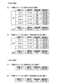
特別結果には、15R確変(図柄)、15R通常(図柄)、2R突確(図柄)、2R中サポ(図柄)、2R潜伏(図柄)の5種類が設定されている。15R確変(図柄)及び15R通常(図柄)は、何れも特別遊技状態でのラウンド数が15ラウンドで、各ラウンドにおける特別変動入賞装置38の開放可能時間は第1開放可能時間(25秒)である。そして、15R確変(図柄)は、特別遊技状態の終了後に確率状態が高確率状態となるとともに次回の大当りまで第1動作状態(高サポ)となる。また、15R通常(図柄)は、特別遊技状態の終了後に確率状態が通常確率状態(低確率)となるとともに70回の特図変動表示ゲームを実行するまで第1動作状態(高サポ)となる。
There are five special results: 15R probability change (symbol), 15R normal (symbol), 2R accuracy (symbol), 2R support (symbol), and 2R latency (symbol). 15R probability variation (symbol) and 15R normal (symbol) are both 15 rounds in the special game state, and the special variable
2R突確(図柄)、2R中サポ(図柄)及び2R潜伏(図柄)は、何れも特別遊技状態でのラウンド数が2ラウンドで、各ラウンドにおける特別変動入賞装置38の開放可能時間は第2開放可能時間(0.5秒)である。また、何れも特別遊技状態の終了後に確率状態が高確率状態となる。そして、2R突確(図柄)は、特別遊技状態の終了後、次回の大当りまで第1動作状態(高サポ)となる。また、2R中サポ(図柄)は、特別遊技状態の終了後、次回の大当りまで第2動作状態(中サポ)となる。また、2R潜伏(図柄)は、特別遊技状態の終了後、通常動作状態となり時短状態とならない。
The 2R accuracy (symbol), 2R support (symbol) and 2R latency (symbol) are both 2 rounds in the special game state, and the special variable
これらの特別結果の選択割合は、第1特図変動表示ゲームと第2特図変動表示ゲームとで異なっている。図6(a)に示すように、第1特図変動表示ゲームでは、15R確変(図柄)及び15R通常(図柄)がそれぞれ30%の確率で選択される。残りの40%は2R大当りとなるが、図6(c)に示すように、2R突確、2R中サポ及び2R潜伏の選択割合は特別結果が発生した際の遊技状態(確率状態や動作状態)によって異なる。例えば、特別結果が発生した際の遊技状態が、通常確率状態(低確)かつ通常動作状態(サポ無)の場合、2R突確及び2R中サポが選択される確率が0%であり、2R潜伏が選択される確率が40%となっている。なお、遊技状態は特別結果の種類に基づき設定されるので、直近の特別結果の種類によって設定される確率状態や普通変動入賞装置37の動作状態により次に発生する特別結果の種類の選択割合が設定されるともいえる。
The selection ratio of these special results is different between the first special figure fluctuation display game and the second special figure fluctuation display game. As shown in FIG. 6A, in the first special figure variation display game, 15R probability variation (symbol) and 15R normal (symbol) are each selected with a probability of 30%. The remaining 40% will be 2R big hit, but as shown in Fig. 6 (c), the selection ratio of 2R accuracy, 2R support and 2R latency is the gaming state when the special result occurs (probability state and operation state) It depends on. For example, if the gaming state when a special result occurs is a normal probability state (low probability) and a normal operation state (no support), the probability that 2R accuracy and support during 2R will be selected is 0%, and 2R latency The probability of being selected is 40%. Since the gaming state is set based on the type of special result, the selection ratio of the type of special result to be generated next depends on the probability state set by the type of the most recent special result or the operating state of the normal
また、第1特図変動表示ゲームでは所定の確率で小当りを発生可能に構成されている。小当りが発生した場合は特定結果が表示されて特定遊技状態となる。特定遊技状態では、2R大当りと同様にラウンド数が2ラウンドで大入賞口の開放時間が第2開放時間(0.5秒)とされる。なお、特定遊技状態の終了後の確率状態や普通変動入賞装置37の動作状態は小当り発生前の状態と同じ状態となる。すなわち、15R確変及び15R通常が第1特別遊技状態を発生させる第1特別結果をなし、2R突確、2R中サポ、2R潜伏が、第1特別遊技状態よりも遊技者に付与される遊技価値が低く、特定遊技状態と同等の遊技価値を付与する第2特別遊技状態を発生させる第2特別結果をなす。なお、2R潜伏及び2R中サポとなる飾り特図変動表示ゲームの実行態様や特別結果とその後の特別遊技状態と、小当りとなる飾り特図変動表示ゲームの実行態様や特定結果とその後の特定遊技状態では、同一の演出が行われるので、遊技者は何れの当りであったのかを判別することが困難である。ただし、特図1表示器51での特別結果と特定結果は異なる図柄である。
Further, the first special figure variation display game is configured to generate a small hit with a predetermined probability. When a small hit occurs, a specific result is displayed and a specific gaming state is entered. In the specific game state, the number of rounds is two rounds as in the case of 2R jackpot, and the opening time of the big prize opening is the second opening time (0.5 seconds). Note that the probability state after the end of the specific gaming state and the operation state of the normal
ここで、大当りとは条件装置の作動を伴う特別結果であり、小当りとは条件装置の作動を伴わない特別結果である。条件装置とは、特図変動表示ゲームで大当りが発生(大当り図柄の停止表示)した場合に作動するもので、条件装置が作動するとは、例えば大当り状態が発生して特別電動役物としての特別変動入賞装置38を連続して作動させるための特定のフラグがセットされることを意味する。条件装置が作動しないとは、例えば小当り抽選に当選したような場合のように上述のフラグはセットされないことを意味する。なお、「条件装置」は上記のようなソフトウェア的にオンオフされるフラグのようなソフトウェア手段であっても良いし、電気的にオンオフされるスイッチのようなハードウェア手段であっても良い。また、「条件装置」は、その作動が電動役物の連続作動に必要条件とされる装置として、パチンコ遊技機の分野においては一般的に使用されている用語であり、本明細書においても同様な意味を有する用語として使用している。
Here, the big hit is a special result with the operation of the condition device, and the small hit is a special result without the operation of the condition device. The condition device is activated when a big hit occurs in the special figure fluctuation display game (stop display of the big hit symbol). When the conditional device is activated, for example, a big hit state occurs and a special electric accessory is generated. This means that a specific flag for continuously operating the variable winning
図7には、演出状態の種類と遷移の条件を示した。演出状態の種類には、通常モード、潜伏モード、確変モード、時短モードがある。各演出状態は、表示される背景の種類やキャラクタの種類、変動表示ゲームの実行態様等が異なり、各演出状態は遊技者が何れの演出状態であるかを認識可能な程度に異なっている。なお、潜伏モードは内部的に潜伏モードAと潜伏モードBに分かれているが、同一の演出を行うものであり、演出のみから潜伏モードAとBのいずれであるかを判別するのは困難である。 FIG. 7 shows the types of effect states and the transition conditions. The types of performance states include a normal mode, a latent mode, a probability change mode, and a time reduction mode. Each effect state differs in the type of background to be displayed, the type of character, the execution mode of the variable display game, and the like, and each effect state is different to the extent that the player can recognize which effect state. Although the latent mode is internally divided into a latent mode A and a latent mode B, the same production is performed, and it is difficult to determine which of the latent modes A and B is based only on the production. is there.
通常モードは通常確率状態(低確率)かつ通常動作状態(サポなし)であることが明確に報知される状態である。この通常モードでは通常動作状態であるので主に第1特図変動表示ゲームが実行されるため、図中には通常確率状態かつ通常動作状態である場合の第1特図変動表示ゲームにおける特別結果の選択割合を示した。 The normal mode is a state in which the normal probability state (low probability) and the normal operation state (no support) are clearly notified. In this normal mode, the first special figure variation display game is mainly executed since it is in the normal operation state. Therefore, the special result in the first special figure variation display game in the normal probability state and the normal operation state is shown in the figure. The selection ratio was shown.
この通常モードにおいて選択可能な2R大当りは2R潜伏のみであり、この2R潜伏となった場合は潜伏モード(潜伏モードA)に移行する。この場合、確率状態は高確率状態となる。また、通常モードにおいて小当りが発生した場合も潜伏モード(潜伏モードA)に移行する。この場合、確率状態は通常確率状態となる。上述したように、遊技者は飾り特図変動表示ゲームや特別遊技状態又は特定遊技状態の演出から2R潜伏と小当りの何れであったのかを判別することが困難である。また、通常モードで2R潜伏又は小当りが発生した場合は、何れも普通変動入賞装置37の動作状態が通常動作状態のままとなるので、この点からも判別することが困難である。よって、2R潜伏と小当りとなった場合に同じ潜伏モードに移行することで、確率状態が判別困難となり、遊技の興趣を向上することができる。
The 2R big hit that can be selected in this normal mode is only the 2R latent, and when this becomes the 2R latent, the mode shifts to the latent mode (latent mode A). In this case, the probability state becomes a high probability state. Also, when a small hit occurs in the normal mode, the mode shifts to the latent mode (latent mode A). In this case, the probability state becomes a normal probability state. As described above, it is difficult for the player to determine whether the game is a 2R latency or a small hit based on the decoration special figure change display game, the special game state, or the specific game state. In addition, when 2R latencies or small hits occur in the normal mode, the operation state of the normal
潜伏モードのうち潜伏モードAは、高確率状態又は通常確率状態かつ通常動作状態となっている状態である。この潜伏モードAでは通常動作状態であるので主に第1特図変動表示ゲームが実行されるため、図中には高確率状態又は通常確率状態かつ通常動作状態である場合の第1特図変動表示ゲームにおける特別結果の選択割合を示した。 Of the latent modes, the latent mode A is a state in which a high probability state or a normal probability state and a normal operation state are established. Since the first special figure variation display game is mainly executed in the latent mode A, the first special figure variation display game in the case of the high probability state or the normal probability state and the normal operation state is shown in the figure. The selection ratio of special results in the display game is shown.
また、潜伏モードのうち潜伏モードBは、高確率状態かつ第2動作状態となっている状態である。この潜伏モードBでは第2動作状態であるが、第2動作状態は通常動作状態と普図確率のみが異なるものであり、主に第1特図変動表示ゲームが実行されるため、図中には高確率状態かつ第2動作状態である場合の第1特図変動表示ゲームにおける特別結果の選択割合を示した。この潜伏モードBでは潜伏モードAと同様の演出が行われ、第2動作状態は通常動作状態と普図確率のみが異なるので外観上は似た状態である。しかし、2R大当りの場合の特別結果の選択割合が異なっているため、同じ潜伏モードでありながら2R大当りとなった場合に選択される特別結果の種類が大きく異なるという斬新な遊技が実行可能となり遊技者の興趣を高めることができる。 In addition, the latent mode B among the latent modes is a state in which a high probability state and a second operation state are established. In this latent mode B, it is the second operation state, but the second operation state is different from the normal operation state only in the normal figure probability, and the first special figure variation display game is mainly executed. Indicates a selection ratio of special results in the first special figure variation display game in the high probability state and the second motion state. In the latent mode B, an effect similar to that of the latent mode A is performed, and the second operation state is similar to the normal operation state because only the normal probability is different. However, since the selection ratio of the special result in the case of 2R big hit is different, a novel game in which the type of special result selected in the case of 2R big hit is greatly different can be executed even in the same latent mode. Can enhance the interest of the person.
潜伏モードでは確率状態を明確に報知しない非報知状態となる。これにより、高確率状態であることへの期待感や特別結果となることへの期待感を高め、遊技の興趣を高めるようにしている。ただし、潜伏モードBであること(高確率状態であること)は普通変動入賞装置37の動作を注意して観察すれば認識可能である。また、通常確率状態で小当りが発生することにより潜伏モードに移行した場合は、移行してから規定回数(ここでは10回)の特図変動表示ゲーム(はずれ結果)を実行すると通常モードへ戻るようになっている。このため、2R大当り又は小当りとなって潜伏モードに移行(再度潜伏モードになった場合も含む)してから規定回数目(ここでは10回目)の特図変動表示ゲームにおいて、潜伏モードが継続するか否かの演出が行われるようになっている。すなわち、この演出が確率状態を示唆する演出となっており、いつまでも確率状態が不明なまま遊技が継続することがなく安心して遊技を行うことができる。ただし、通常確率状態であっても規定回数目の特図変動表示ゲームで小当りとなった場合は通常確率状態のまま再度潜伏モードとなるので、必ずしも確率状態が明確に報知されるものではない。
In the latent mode, it becomes a non-notification state in which the probability state is not clearly notified. As a result, the expectation for being in a high probability state and the expectation for being a special result are enhanced, and the interest of the game is enhanced. However, the latent mode B (high probability state) can be recognized by carefully observing the operation of the normal
各モードで15R確変又は2R確変となると確変モードに移行する。確変モードは高確率状態(高確率)かつ第1動作状態(高サポ)であることが明確に報知される状態である。この確変モードでは第1動作状態であるので主に第2特図変動表示ゲームが実行されるため、図中には第2特図変動表示ゲームにおける特別結果の選択割合を示した。第2特図変動表示ゲームでは2R大当りが発生しないため、確実に出球を獲得できる。 When the 15R or 2R probability change occurs in each mode, the mode changes to the probability change mode. The probability variation mode is a state in which it is clearly notified that the state is a high probability state (high probability) and the first operation state (high support). Since the second special figure variation display game is mainly executed in this probability variation mode since it is the first operation state, the selection ratio of the special result in the second special figure variation display game is shown in the figure. Since the 2R big hit does not occur in the second special figure fluctuation display game, it is possible to surely get a ball.
各モードで15R通常となると時短モードに移行する。時短モードは通常確率状態(低確率)かつ第1動作状態(高サポ)であることが明確に報知される状態である。この時短モードでは第1動作状態であるので主に第2特図変動表示ゲームが実行されるため、図中には第2特図変動表示ゲームにおける特別結果の選択割合を示した。この時短モードで70回の特図変動表示ゲームを実行すると、通常動作状態となり通常モードに移行する。 When it becomes 15R normal in each mode, it shifts to the time reduction mode. The time reduction mode is a state in which it is clearly notified that the normal probability state (low probability) and the first operation state (high support) are present. Since the second special figure variation display game is mainly executed in this short time mode since it is the first operation state, the selection ratio of the special result in the second special figure variation display game is shown in the figure. At this time, when the special figure variation display game is executed 70 times in the short mode, the normal operation state is entered and the normal mode is entered.
このような特別結果の種類の選択割合及び演出状態の遷移とすることで、斬新な遊技が実行可能となり、遊技の興趣を向上することができる。例えば、特別遊技状態の終了後に、高確率状態かつ第2動作状態となった場合と、高確率状態かつ通常動作状態となった場合とで同一の特定演出状態(潜伏モード)を設定するので、異なる遊技状態を同一の遊技状態のように見せることができる。同じ特定演出状態であっても、第2動作状態である場合と、通常動作状態である場合とで遊技球の消費量が異なるため、特定演出状態での遊技に変化が生まれ、遊技の興趣を向上することができる。また、高確率状態ではあるが、第1動作状態である場合よりも遊技球の消費量が多い状態において、他の状態では行われないような演出をすることも可能となるので斬新な遊技が実行可能となり、遊技を継続する意欲が削がれることを防止できる。 By making such a selection ratio of special result types and transition of the production state, a novel game can be executed and the interest of the game can be improved. For example, after the special gaming state ends, the same specific performance state (latent mode) is set when the high probability state and the second operation state are entered and when the high probability state and the normal operation state are established. Different gaming states can appear as the same gaming state. Even in the same specific performance state, the amount of game balls consumed is different between the second operation state and the normal operation state. Can be improved. In addition, although it is a high probability state, in a state where the amount of game balls consumed is larger than in the case of the first operation state, it is possible to produce an effect that is not performed in other states, so a novel game is It becomes feasible and can prevent the desire to continue playing from being lost.
また、同じ潜伏モードでも、高確率状態かつ第2動作状態(潜伏モードB)である場合と、高確率状態又は通常確率状態かつ通常動作状態(潜伏モードA)である場合とで特別結果の種類の選択割合(特別遊技状態の終了後における普通変動入賞装置37の動作状態の選択割合)が異なっているので、潜伏モードにおいて次に選択される特別結果の種類の傾向(普通変動入賞装置37の動作状態の傾向)を異ならせることができ、斬新な遊技が実行可能となり遊技者の興趣を高めることができる。
Also, even in the same latent mode, there are special results depending on whether the state is the high probability state and the second operation state (latency mode B) or the high probability state or the normal probability state and the normal operation state (latency mode A). Since the selection ratio (selection ratio of the operation state of the normal
また、高確率状態かつ第1動作状態となる特別結果(15R確変及び2R突確)の選択割合は、通常確率状態かつ通常動作状態である場合(通常モード)よりも高確率状態かつ通常動作状態である場合(潜伏モードA)の方が高く、さらに高確率状態かつ第2動作状態である場合(潜伏モードB)の方が高い。すなわち、通常モードである場合よりも潜伏モードである場合の方が遊技者にとって最も有利な状態への移行割合が高いので、潜伏モードを経由することにより確変モードへ移行しやすくなるような印象を与えることができ、第1動作状態である場合よりも遊技球の消費量が多い潜伏モードであっても遊技を継続する意欲が削がれることがないようにすることができる。また、同じ潜伏モードであっても、通常動作状態よりも遊技者にとって有利な第2動作状態である場合の方が、遊技者にとって最も有利な状態への移行割合が高いので、同じ潜伏モードにおける動作状態の違いに基づく差異を大きくすることができ、斬新な遊技が実行可能となり遊技の興趣を向上することができる。 In addition, the selection ratio of the special result (15R probability variation and 2R accuracy) that becomes the high probability state and the first operation state is higher in the probability state and the normal operation state than in the normal probability state and the normal operation state (normal mode). In some cases (latent mode A) is higher, and in the case of a high probability state and the second operating state (latent mode B), it is higher. In other words, since the rate of transition to the most advantageous state for the player is higher in the latent mode than in the normal mode, the impression that it is easier to shift to the probability change mode through the latent mode. It is possible to prevent the willingness to continue the game from being lost even in the latent mode in which the amount of game balls consumed is greater than in the first operation state. In addition, even in the same latent mode, the rate of transition to the most advantageous state for the player is higher in the second operational state advantageous to the player than in the normal operational state. The difference based on the difference in operation state can be increased, and a novel game can be executed, so that the interest of the game can be improved.
また、高確率状態かつ通常動作状態となる特別結果(2R潜伏、すなわち潜伏モードAに移行する特別結果)の選択割合は、高確率状態かつ第1動作状態(確変モード)又は第2動作状態(潜伏モードB)である場合よりも高確率状態かつ通常動作状態(潜伏モードA)である場合の方が高い。よって、高確率状態であっても遊技球の消費量が多い通常動作状態である場合には特別結果が導出されても再び通常動作状態となる可能性が高いが、遊技球の消費量が通常動作状態よりも少ない第1又は第2動作状態であれば、再び第1又は第2動作状態となる可能性が高い。すなわち、同じ高確率状態であっても、遊技者にとって不利な状態が連続する可能性が高い反面、有利な状態が連続する可能性も高く、有利な状態と不利な状態の差が大きい斬新な遊技が実行可能となり、遊技者の興趣を高めることができる。そして、遊技球の消費量が多い通常動作状態であっても高確率状態であれば遊技を継続することとなるので、遊技店と遊技者の利益のバランスを保つことができる。 In addition, the selection ratio of the special result (2R latency, that is, the special result that shifts to the latent mode A) that becomes the high probability state and the normal operation state is the high probability state and the first operation state (probability change mode) or the second operation state ( The case of the high probability state and the normal operation state (latency mode A) is higher than the case of the latent mode B). Therefore, even in a high probability state, in the normal operation state where the amount of game balls consumed is large, there is a high possibility that the normal operation state will be resumed even if a special result is derived. If the first or second operation state is smaller than the operation state, there is a high possibility that the first or second operation state is reached again. That is, even in the same high probability state, there is a high possibility that the disadvantageous state continues for the player, but the advantageous state is also likely to continue, and the difference between the advantageous state and the disadvantageous state is large and innovative. The game can be executed and the interest of the player can be enhanced. And even if it is a normal operation state with much consumption of game balls, if it is a high probability state, it will continue a game, Therefore The balance of the profit of a game store and a player can be maintained.
また、高確率状態かつ第2動作状態(潜伏モードB)である場合は、高確率状態かつ通常動作状態となる特別結果(2R潜伏)を選択しない。よって、潜伏モードBから2R突確の選択割合が低い潜伏モードAに移行することがなく、遊技者にとって有利な状態が連続する可能性が高まり、有利な状態と不利な状態の差が大きくなり遊技者の興趣を高めることができる。 In the case of the high probability state and the second operation state (latency mode B), the special result (2R latency) that becomes the high probability state and the normal operation state is not selected. Therefore, there is no transition from the latent mode B to the latent mode A where the selection ratio of 2R accuracy is low, and the possibility that the player is in an advantageous state increases, and the difference between the advantageous state and the disadvantageous state increases. Can enhance the interest of the person.
また、第2変動表示ゲームの場合は2R大当りが選択されない。すなわち、通常動作状態または第2動作状態となる特別結果(2R潜伏、2R中サポ)は選択されない。これにより、第2始動入賞口への入賞が通常動作状態よりも容易となる第1又は第2動作状態であれば確実に出球を獲得でき、さらに第1動作状態が連続するようになり、遊技者にとって有利な状態が連続する可能性が高まるので、有利な状態と不利な状態の差が大きくなり遊技の興趣を高めることができる。 In the case of the second variation display game, 2R jackpot is not selected. That is, the special result (2R latency, support during 2R) that becomes the normal operation state or the second operation state is not selected. As a result, if the first or second operation state in which the winning to the second start winning opening is easier than the normal operation state, it is possible to reliably obtain the ball, and the first operation state continues. Since a possibility that a state advantageous for a player continues will increase, the difference between an advantageous state and a disadvantageous state becomes large, and the interest of a game can be improved.
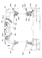
次に、本発明の実施形態の遊技機10におけるセンターケース40の詳細について説明する。
センターケース40は、図8に示すように表示部41aを有する表示装置41の前面側に前面構成部材600と、下方装飾演出部材753a、753b等を有する裏面構成部材700とを備えて構成されている。
Next, details of the
As shown in FIG. 8, the
前面構成部材600は、図9に示すように、環状のベースフレーム部材610と、前面構成部材600の上方から流下する遊技球の流入を阻止する左上側鎧部材620、左側鎧部材630及び右側鎧部材640と、前面構成部材600の左側部の外側から内側へ遊技球を移動させるワープ装置650と、ワープ装置650を経由して前面構成部材600の内側へ移動した遊技球を転動させるステージ部662を有するステージ構成部材660と、前面構成部材600の枠部を発光させる装飾発光部材670と、前面構成部材600の枠部を装飾する装飾部材680と、を備えている。
As shown in FIG. 9, the front
ワープ装置650は、当該装置650の入口を形成するワープ入口部材652と、当該装置650に流入した遊技球をステージ部662に流下させるワープ通路部材654と、を備えている。
The
ワープ入口部材652は、前面構成部材600の左側部の外側から流下した遊技球を流入可能に形成されており、当該部材に流入した遊技球を遊技盤30の後方へ誘導するように形成されている。
The
ワープ通路部材654は、前側通路部材654aと、後側通路部材654bと、を備えて構成されている。
前側通路部材654aは、その上端部がワープ入口部材652に接続されるようになっている。そして、前側通路部材654aは、ワープ入口部材652により遊技盤30の後方へ誘導された遊技球を右下方に流下させることができるようになっている。
また、前側通路部材654aの下端部は、当該通路部材を流下する遊技球を遊技盤30のさらに後方へ誘導するように形成されている。
後側通路部材654bは、前側通路部材654aの後壁をなす部材であるとともに、前側通路部材654aにより遊技盤30の後方へ誘導された遊技球をステージ部662へ排出する方向転換部材をなしている。
The
The
Further, the lower end portion of the
The
装飾発光部材670は、前面構成部材600の左側部を装飾発光させる左側装飾発光部材672と、当該前面構成部材600の上部を装飾発光させる上装飾発光部材674と、当該前面構成部材600の右側部を装飾発光させる右側装飾発光部材676と、当該前面構成部材600の下部を装飾発光させる下装飾発光部材678と、を備えて構成されている。
The decorative
左側装飾発光部材672は、主に左側鎧部材630に設けられたクリア部材やワープ装置650を後方から間接的に発光させる部材であり、複数のLEDを配設した左側LED基板672aと、当該左側LED基板672aを後方から覆う左側LED基板カバー部材672bと、を備えている。
The left decorative
上装飾発光部材674は、主に右側鎧部材640の上部に設けられたクリア部材を後方から間接的に発光させる部材であり、複数のLEDを配設した上LED基板674aと、当該上LED基板674aを後方から覆う上LED基板カバー部材674bと、を備えている。
The upper decoration light-emitting
右側装飾発光部材676は、例えば、特図変動表示ゲームにおける大当りへ期待度をレベルメータにより発光表示する部材であり、図示は省略するが当該メータに対応する位置に複数のLEDを配設した右側LED基板と、当該右側LED基板を後方から覆う右側LED基板カバー部材と、を備えている。
The right decoration
下装飾発光部材678は、主にステージ構成部材660後方から間接的に発光させる部材であり、複数のLEDを配設した下LED基板678aと、当該下LED基板678aを後方から覆う下LED基板カバー部材678bと、を備えている。
下LED基板カバー部材678bは、ステージ構成部材660のステージ部662より上方に延設された延設部678b1を有している。これにより、延設部678b1は、ステージ部662を転動する遊技球が当該ステージ部662の後側へ進入することを防止している。また、延設部678b1は、クリア部材で構成されており、当該延設部678b1の後側に配設された下方可動演出部材751や下方装飾演出部材753a、753bを遊技盤30の前面側から視認可能となっている。
The lower decorative
The lower LED
装飾部材680は、前面構成部材600の左側上部を装飾する左上装飾部材681と、左側鎧部材630を装飾する左側鎧部材装飾部材682と、ワープ装置650の前面を装飾するワープ装置装飾部材683と、前面構成部材600の下部を装飾する下装飾部材684、685と、前面構成部材600の右側下部を装飾する右下装飾部材686、687と、を備えて構成されている。
The
右下装飾部材686は、遊技盤30の前面側に突出するように配設されている(図35参照)。これにより、センターケース40の右下方を流下する遊技球が障害釘に衝突し跳ね上った場合でも、当該右下装飾部材686が遊技盤30の前面側に突出して設けられていることにより、当該右下装飾部材686が障害となり当該遊技球がステージ部662に進入することを防止することができるようになっている。
また、右下装飾部材686は、その上面に跳ね上がった遊技球を当該右下装飾部材686の左下方に配設された始動入賞口36へ誘導する球流下開口部686aを備えている。
The lower right
Further, the lower right
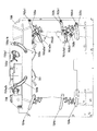
次に、裏面構成部材700の詳細について、図10〜図14を用いて説明する。
図10は裏面構成部材700の正面図、図11は裏面構成部材700の斜視図、図12は裏面構成部材700の分解斜視図、図13は裏面構成部材700を構成する上方装飾演出装置740及び下方可動演出装置750の分解斜視図、図14は裏面構成部材700を構成する第1可動演出装置730、第2可動演出装置760、及び第3可動演出装置770の分解斜視図である。
Next, details of the
10 is a front view of the back
裏面構成部材700は、図10〜図12に示すように、前面が開口した箱形形状の制御ベース部材710と、当該制御ベース部材710の底部に配設される駆動ベース部材720と、当該駆動ベース部材720の上部に配設される第1可動演出装置730及び上方装飾演出装置740と、当該駆動ベース部材720の下部に配設される下方可動演出装置750と、当該駆動ベース部材720の左側部に配設される第2可動演出装置760と、当該駆動ベース部材720の右側部に配設される第3可動演出装置770と、を備えている。
As shown in FIGS. 10 to 12, the
制御ベース部材710は、透明な材質(クリア部材)からなり当該制御部材710の中央には、表示装置41の表示部41aに対応するように矩形状の開口710aが形成されている。
また、制御ベース部材710は、当該制御ベース部材710の外周に前方へ延出する板状の周囲壁710bを備えている。そして、当該周囲壁710bの前端部が遊技盤30や前面構成部材600に接続するようになっている。
The
Further, the
駆動ベース部材720は、透明又は半透明な平板部材からなり、当該駆動ベース部材720の中央には、制御ベース部材710と同様に、表示装置41の表示部41aに対応するように矩形状の開口720aが形成されている。
また、駆動ベース部材720の上部には第1可動演出部材731(後述)を案内するための上ガイド溝726a、726bが設けられ、駆動ベース部材720の左側部には連動可動演出部材762(後述)を案内するための左側ガイド溝722a〜cが設けられ、駆動ベース部材720の右側部には連動可動演出部材772(後述)を案内するための右側ガイド溝724a〜cが設けられている。
The
In addition,
上方装飾演出装置740は、図13に示すように、円板状の円板装飾部材741と、当該円板装飾部材741の近傍を装飾する第1補助装飾部材742と、ロゴタイプ(例えば、遊技機10のタイトル等)を形成したロゴタイプ装飾部材743と、当該ロゴタイプ装飾部材743の近傍を装飾する第2補助装飾部材744と、これらの装飾部材に後方から光を照射する複数のLEDを有するLED基板745と、当該LED基板745の前面を保護する前面カバー部材746と、円板装飾部材741、ロゴタイプ装飾部材743、及びLED基板745を取り付けるための上方装飾演出ベース部材747と、を備えている。
As shown in FIG. 13, the upper
円板装飾部材741は、透明又は半透明なクリア部材で構成され、当該円板装飾部材741の左下部には第1補助装飾部材742を取り付けるための取付用ボス741aを備えている。
第1補助装飾部材742は、花を模した装飾部材であり、その裏面に取付用ボス741aに取り付け可能な突起部742aを備えている。
The
The first auxiliary
ロゴタイプ装飾部材743は、透明又は半透明なクリア部材で構成され、当該ロゴタイプ装飾部材743の右側部には第2補助装飾部材744を取り付けるための突起部743aを備えている。
第2補助装飾部材744は、花を模した装飾部材であり、当該第2補助装飾部材744の左上部には突起部743aに取り付け可能な取付用ボス744aを備えている。
The logo type
The second auxiliary
LED基板745は、当該基板の平面上に上方装飾演出ベース部材747に複数設けられた位置決め用ボス747a、747a、…に挿通可能な位置決め孔745a、745a、…を有している。また、LED基板745は、円板装飾部材741及びロゴタイプ装飾部材743を上方装飾演出ベース部材747に取り付けるときのビス止め孔を複数有している。
The
前面カバー部材746は、LED基板745に配設されたLEDに他の装置の部材等が接触することを防止するカバー部材である。また、前面カバー部材746は、LED基板745と同様に、上方装飾演出ベース部材747に複数設けられた位置決め用ボス747a、747a、…に挿通可能な位置決め孔746a、746a、…や、円板装飾部材741及びロゴタイプ装飾部材743を上方装飾演出ベース部材747に取り付けるときのビス止め孔を複数有している。
The
上方装飾演出ベース部材747は、上述したように、円板装飾部材741やロゴタイプ装飾部材743、LED基板745を取り付けるためのベース部材であるとともに、後述する第1可動演出装置730の第1駆動機構部732、第2可動演出装置760の第2駆動機構部763、及び第3可動演出装置770の第3駆動機構部773の前面側を覆うカバー部材としての機能を有する部材である。
As described above, the upper decoration
下方可動演出装置750は、図13に示すように、下方可動演出部材751と、下方可動演出部材751を駆動する下方可動演出部材駆動部752と、下方可動演出部材751の両側を装飾する下方装飾演出部材753a、753bと、を備えている。
As shown in FIG. 13, the lower
下方可動演出部材751は、下方可動演出部材駆動部752による駆動力によって上下方向に往復移動することが可能となっている。
具体的には、下方可動演出部材751は、初期状態にあるとき遊技盤30の前面側から見て表示装置41の表示部41aと重ならない位置にある。そして、下方可動演出部材駆動部752による出力があると、下方可動演出部材751は、上方に移動して表示部41aと前後方向において重なる位置で所定時間保持されるようになっている。
The downward
Specifically, the downward
第1可動演出装置730は、図14に示すように、第1可動演出部材731と、第1可動演出部材731を駆動する第1駆動機構部732と、第1駆動機構部732による駆動力を第1可動演出部材731に伝達する第1伝達機構部733と、第1可動演出部材731の初期位置を検出するための位置検出センサ734と、を備えている。
As shown in FIG. 14, the first
第1可動演出部材731は、仮面を模した部材で構成され、その裏面には連結ピン733c、733cの一端側を嵌め込み可能な挿通穴(図示省略)を2つ有している。なお、第1可動演出部材731は、左右対称となる位置に当該挿通穴を設けている。
The first
第1駆動機構部732は、第1駆動モータ732aと、第1駆動ギヤ部732bと、第1駆動モータ732aを固定するとともに第1駆動ギヤ部732bの前面側を覆う第1駆動機構部カバー部材732cと、を備えている。
The first
第1駆動ギヤ部732bは、第1駆動モータ732aのモータ軸732a1に軸支される駆動ギヤ732b1と、駆動ギヤ732b1とそれぞれ歯合する第1従動ギヤ732b2及び第2従動ギヤ732b3と、第2従動ギヤ732b3と歯合する第3従動ギヤ732b4と、を備えている(図19参照)。
The first
第1従動ギヤ732b2は、後述する第1左側アーム部材733a1の一端に設けられたギヤ部733a1aと歯合するようになっている。また、第3従動ギヤ732b4は、後述する第1右側アーム部材733a2の一端に設けられたギヤ部733a2aと歯合するようになっている。
なお、第1〜第3従動ギヤ732b2〜4はそれぞれ同一の歯数・ピッチ円を有する平歯車となっている。そして、第3従動ギヤ732b4は、上術のように駆動ギヤ732b1との間に第2従動ギヤ732b3を介しているので、駆動ギヤ732b1を回動させると、第3従動ギヤ732b4は、第1従動ギヤ732b2と同一の回転速度で回動するが逆回転方向に回動することとなる。従って、第1左側アーム部材733a1と第1右側アーム部材733a2とは左右対称で同時に動かすことが可能となっている。
The first driven gear 732b2 meshes with a gear portion 733a1a provided at one end of a first left arm member 733a1 described later. The third driven gear 732b4 meshes with a gear portion 733a2a provided at one end of a first right arm member 733a2 described later.
The first to third driven gears 732b2 to 4 are spur gears having the same number of teeth and a pitch circle. Since the third driven gear 732b4 is interposed between the second driven gear 732b3 and the drive gear 732b3 as described above, when the drive gear 732b1 is rotated, the third driven gear 732b4 is Although it rotates at the same rotational speed as the driven gear 732b2, it rotates in the reverse rotation direction. Therefore, the first left arm member 733a1 and the first right arm member 733a2 are symmetrical and can be moved simultaneously.
第1伝達機構部733は、第1アーム部材733aと、第1アーム部材733aの一端と回動可能に接続する第2アーム部材733bと、当該第2アーム部材733bと第1可動演出部材731とを連結する連結ピン733cと、トーションバネ733dと、を備えている。
The first
第1アーム部材733aは、第1左側アーム部材733a1と、第1右側アーム部材733a2と、を備えている。なお、第1左側アーム部材733a1と第1右側アーム部材733a2は左右対称の一対の部材で構成されており、以下第1左側アーム部材733a1の詳細についてのみ説明し、第1右側アーム部材733a2の説明については省略する。
The
第1左側アーム部材733a1は、その一端にギヤ部733a1aを備えている(図19参照)。第1左側アーム部材733a1は、ギヤ部733a1aと第1従動ギヤ732b2とを歯合させることで、当該ギヤ部733a1aが設けられた一端側を回動中心として回動させることが可能となっている。
また、第1左側アーム部材733a1は、その他端側の表面側において接続ピンを介して後述する第2左側アーム部材733b1と回動可能に接続するようになっている。また、第1左側アーム部材733a1は、その他端側の裏面に第1左側アーム部材733a1の回動範囲を規制するための規制ピン733a1bを備えている。規制ピン733a1bは、上ガイド溝726aに挿通され、当該上ガイド溝726aを摺動可能となっている。
The first left arm member 733a1 includes a gear portion 733a1a at one end thereof (see FIG. 19). The first left arm member 733a1 can be rotated around the one end side where the gear portion 733a1a is provided by engaging the gear portion 733a1a and the first driven gear 732b2. .
Further, the first left arm member 733a1 is rotatably connected to a second left arm member 733b1 described later via a connection pin on the surface side on the other end side. The first left arm member 733a1 includes a regulation pin 733a1b for regulating the rotation range of the first left arm member 733a1 on the back surface on the other end side. The regulation pin 733a1b is inserted into the
第2アーム部材733bは、第2左側アーム部材733b1と、第2右側アーム部材733b2と、を備えている。第2左側アーム部材733b1と第2右側アーム部材733b2は左右対称の一対の部材で構成されている。
以下、第2左側アーム部材733b1の詳細について説明し、第2右側アーム部材733b2については第2左側アーム部材733b1と異なる部分についてのみ説明する。
The
Hereinafter, the details of the second left arm member 733b1 will be described, and only the portions of the second right arm member 733b2 that are different from the second left arm member 733b1 will be described.
第2左側アーム部材733b1は、その一端が接続ピンを介して第1左側アーム部材733a1と回動可能に接続するようになっている。また、第2左側アーム部材733b1は、その他端にギヤ部733b1aを備えており、第2右側アーム部材733b2に設けられたギヤ部733b2aと歯合するようになっている。
第2右側アーム部材733b2は、第1右側アーム部材733a2と接続される側の端部に突片733b2bを備えており、位置検出センサ734によって当該突片733b2bを検出することで、第1可動演出部材731の初期位置を検出可能となっている。
One end of the second left arm member 733b1 is rotatably connected to the first left arm member 733a1 via a connection pin. The second left arm member 733b1 includes a gear portion 733b1a at the other end, and meshes with the gear portion 733b2a provided on the second right arm member 733b2.
The second right arm member 733b2 includes a projecting piece 733b2b at the end connected to the first right arm member 733a2, and the
連結ピン733c、733cは左右一対の部材であり、その一端はギヤ部733b1a、733b2aにそれぞれ挿通され、その他端はそれぞれ第1可動演出部材731の裏面に嵌め込まれるようになっている。
The connection pins 733c and 733c are a pair of left and right members, one end of which is inserted into the gear portion 733b1a and 733b2a, and the other end is fitted into the back surface of the first
トーションバネ733d、733dは左右一対の部材であり、第1左側アーム部材733a1と第1右側アーム部材733a2の回動中心部周りにそれぞれ設けられ、その復元力が第1可動演出部材731を初期位置に戻すときの動作補助に用いられる。
The torsion springs 733d and 733d are a pair of left and right members, which are provided around the rotation center portions of the first left arm member 733a1 and the first right arm member 733a2, respectively, and the restoring force causes the first
位置検出センサ734は、第1可動演出部材731が初期位置にあることを検出するためのセンサであり、上ガイド溝726の上端の近傍に配設される(図19参照)。
The
第2可動演出装置760は、図14に示すように、第2可動演出部材761と、第2可動演出部材761と連動して動く連動可動演出部材762と、第2可動演出部材761を駆動する第2駆動機構部763と、第2可動演出部材761の初期位置を検出するための位置検出センサ764と、を備えている。
As shown in FIG. 14, the second
第2可動演出部材761は、左上可動演出部材761aと、左下可動演出部材761bと、を備えている。
The second
左上可動演出部材761aは、前面側左上可動演出部材761a1と、裏面側左上可動演出部材761a2と、前面側左上可動演出部材761a1及び裏面側左上可動演出部材761a2により挟持されるLED基板761a3及び突片761a4と、トーションバネ761a5と、を備えている。
The upper left
前面側左上可動演出部材761a1は、ハート形状の前面側左上本体部761a1aと、前面側左上アーム部761a1bと、を備えている。
前面側左上アーム部761a1bは、その一端が前面側左上本体部761a1aに接続され、他端が後述する第2駆動機構部763の第4従動ギヤ763b5に接続され、当該他端側を回動中心として回動可能となっている。
The front side upper left movable effect member 761a1 includes a heart-shaped front side upper left main body part 761a1a and a front side upper left arm part 761a1b.
One end of the front-side upper left arm portion 761a1b is connected to the front-side upper left main body portion 761a1a, the other end is connected to a fourth driven gear 763b5 of the second
トーションバネ761a5は、左上可動演出部材761aの回動中心部周りに設けられ、その復元力が左上可動演出部材761aを初期位置に戻すときの動作補助に用いられる。
The torsion spring 761a5 is provided around the rotation center portion of the upper left
裏面側左上可動演出部材761a2は、ハート形状の裏面側左上本体部761a2aと、裏面側左上アーム部761a2bと、を備えている。
裏面側左上本体部761a2aは、その平面上に後述する左上連動可動演出部材762aの連結ピン762a2を挿通させるための長孔761a2a1を有している(図26参照)。
The back side upper left movable effect member 761a2 includes a heart-shaped back side upper left main body part 761a2a and a back side upper left arm part 761a2b.
The back side upper left main body portion 761a2a has a long hole 761a2a1 through which a connecting pin 762a2 of an upper left interlocking
左下可動演出部材761bは、前面側左下可動演出部材761b1と、裏面側左下可動演出部材761b2と、前面側左下可動演出部材761b1及び裏面側左下可動演出部材761b2により挟持されるLED基板(図示省略)と、を備えている。
The lower left
前面側左下可動演出部材761b1は、ハート形状の前面側左下本体部761b1aと、左下アーム部761b1bと、を備えている。
左下アーム部761b1bは、その一端が前面側左下本体部761b1aに接続され、他端が後述する第2駆動機構部763の第2従動ギヤ763b3に接続され、当該他端側を回動中心として回動可能となっている。
The front side lower left movable effect member 761b1 includes a heart-shaped front side lower left main body part 761b1a and a lower left arm part 761b1b.
One end of the lower left arm portion 761b1b is connected to the front lower left main body portion 761b1a, the other end is connected to a second driven gear 763b3 of the second
また、左下アーム部761b1bは、当該アームの途中に左下アーム部761b1bの動作範囲を規制するための規制部761b1b1を備えている。この規制部761b1b1は、規制ピン761b1b2を備えており、後述する駆動機構部ベース部材763cに設けられた長孔763c1に挿通されるようになっている。
The lower left arm portion 761b1b includes a restricting portion 761b1b1 for restricting the operating range of the lower left arm portion 761b1b in the middle of the arm. The restriction portion 761b1b1 includes a restriction pin 761b1b2, and is inserted into a long hole 763c1 provided in a drive
裏面側左下可動演出部材761b2は、ハート形状の裏面側左下本体部761b2aを備えている(図15参照)。
裏面側左下本体部761b2aは、その平面上に後述する左下連動可動演出部材762bの連結ピン762b2を挿通させるための長孔761b2a1を有している。
The back side lower left movable effect member 761b2 includes a heart-shaped back side lower left main body part 761b2a (see FIG. 15).
The back side lower left main body portion 761b2a has a long hole 761b2a1 through which a connecting pin 762b2 of a lower left interlocking
連動可動演出部材762は、左上可動演出部材761aに連動する左上連動可動演出部材762aと、左下可動演出部材761bに連動する左下連動可動演出部材762bと、を備えている。
The linked
左上連動可動演出部材762aは、左上連動可動演出部材762aの移動先を案内する案内ピン762a1と、左上可動演出部材761aと連結させる連結ピン762a2と、を備えている。
案内ピン762a1は、左上連動可動演出部材762aの後方に向かって突設され、左側ガイド溝722aに挿通されるようになっている。連結ピン762a2は、左上連動可動演出部材762aの前方に向かって突設され、裏面側左上本体部761a2aの長孔761a2a1に挿通されるようになっている。
The upper left interlocking
The guide pin 762a1 protrudes toward the rear of the upper left interlocking
左下連動可動演出部材762bは、左下連動可動演出部材762bの移動先を案内する第1案内ピン762b1及び第2案内ピン762b2と、左下可動演出部材761bと連結させる連結ピン762b3と、を備えている。
第1案内ピン762b1は、左下連動可動演出部材762bの後方に向かって突設され、左側ガイド溝722bに挿通されるようになっている。また、第2案内ピン762b2は、第1案内ピン762b1と同様に、左下連動可動演出部材762bの後方に向かって突設され、左側ガイド溝722cに挿通されるようになっている。連結ピン762b3は、左下連動可動演出部材762bの前方に向かって突設され、裏面側左下本体部761b2aの長孔761b2a1に挿通されるようになっている。
The lower left interlocking
The first guide pin 762b1 protrudes toward the rear of the lower left interlocking
第2駆動機構部763は、第2駆動モータ763aと、第2駆動ギヤ部763bと、第2駆動モータ763aを固定するとともに第2駆動ギヤ部763bを配設する駆動機構部ベース部材763cと、を備えている。
The second
第2駆動ギヤ部763bは、第2駆動モータ763aのモータ軸763a1に軸支される駆動ギヤ763b1と、駆動ギヤ763b1とそれぞれ歯合する第1従動ギヤ763b2と、第1従動ギヤ763b2と歯合する第2従動ギヤ763b3と、第2従動ギヤ763b3と歯合する第3従動ギヤ763b4と、第3従動ギヤ763b4と歯合する第4従動ギヤ763b5と、を備えている(図15、図37参照)。
The second
第2従動ギヤ763b3には、左下アーム部761b1bが接続され、第2従動ギヤ763b3の回動に連動して左下可動演出部材761bを回動させることが可能となっている。
第4従動ギヤ763b5には、前面側左上アーム部761a1bが接続され、第4従動ギヤ763b5の回動に連動して左上可動演出部材761aを回動させることが可能となっている。
The lower left arm 761b1b is connected to the second driven gear 763b3, and the lower left
The front left upper arm portion 761a1b is connected to the fourth driven gear 763b5, and the upper left
駆動機構部ベース部材763cは、その左側部に左下アーム部761b1bの規制ピン761b1b2を挿通させることが可能な長孔763c1を有している。
また、駆動機構部ベース部材763cは、第2駆動モータ763a及び第2駆動ギヤ部763bを配設するとともに、第3駆動機構部773の第3駆動モータ773a及び第3駆動ギヤ部773bを配設することができるようになっている。
The drive
The drive
位置検出センサ764は、左上可動演出部材761aが初期位置にあることを検出するためのセンサであり、具体的には、突片761a4を検出することによって、左上可動演出部材761aを検出することができるようになっている。
The
第3可動演出装置770は、図14に示すように、第3可動演出部材771と、第3可動演出部材771と連動して動く連動可動演出部材772と、第3可動演出部材771を駆動する第3駆動機構部773と、第3可動演出部材771の初期位置を検出するための位置検出センサ774と、を備えている。
なお、第2可動演出装置760と第3可動演出装置770は左右対称の部材で構成されており、第3可動演出装置770については第2可動演出装置760と異なる部分についてのみ説明する。
As shown in FIG. 14, third
Note that the second
右下アーム部771b1bは、当該アームの途中に右下アーム部771b1bの動作範囲を規制するための規制部771b1b1を備えている。この規制部771b1b1は、規制ピン771b1b2を備えており、駆動ベース部材720に設けられる長孔形成部材728の長孔728aに挿通されるようになっている。
The lower right arm portion 771b1b includes a restriction portion 771b1b1 for restricting the operation range of the lower right arm portion 771b1b in the middle of the arm. The restriction portion 771b1b1 includes a restriction pin 771b1b2, and is inserted into a
次に、第1可動演出装置730の動作態様について、図15〜図23を用いて説明する。
ここで、第1駆動機構部732は、第2駆動機構部763及び第3駆動機構部773の非作動時に作動するように、演出制御装置300によって制御されている。
Next, the operation | movement aspect of the 1st movable production |
Here, the first
図15及び図16は、第1可動演出部材731の動作前の態様を示す裏面構成部材700の正面図であり、具体的には、図15は、第1可動演出部材731を取り外した状態を示す図、図16は、第1可動演出部材731を取り付けた状態を示す図である。なお、図15〜図23は、説明の都合上、上方装飾演出装置740や下方可動演出装置750、第2可動演出装置760、第3可動演出装置770等を取り外した状態の図としている。
15 and 16 are front views of the back
図15に示すように、第1可動演出装置730の第1伝達機構部733は、第1左側アーム部材733a1、第1右側アーム部材733a2、第2左側アーム部材733b1、及び第2右側アーム部材733a2の4節のリンクによって菱形リンク機構を構成している。そして、第2左側アーム部材733b1及び第2右側アーム部材733a2の端部に接続される第1可動演出部材731を昇降可能としている。
As shown in FIG. 15, the
図16に示すように、第1可動演出部材731が初期位置にあるとき、遊技盤30の前方から見たときに、第1可動演出部材731が表示装置41の表示部41aの前面に重ならない位置にある。また、このとき、位置検出センサ734によって、第2右側アーム部材733b2の突片733b2bを検出することで、第1可動演出部材731が初期位置にあることを検出している(図15参照)。
As shown in FIG. 16, when the first
図17及び図18は、第1可動演出部材731の動作前の態様を示す裏面構成部材700の裏面図であり、具体的には、図17は、第1可動演出部材731を取り外した状態を示す図、図18は、第1可動演出部材731を取り付けた状態を示す図である。
FIGS. 17 and 18 are rear views of the back
図17及び図18に示すように、第1可動演出部材731が初期位置にあるとき、規制ピン733a1b、733a2bは、それぞれ対応する上ガイド溝726、726の上端部にある。
As shown in FIGS. 17 and 18, when the first
図19〜図21は、第1可動演出部材731が動作中(下降中)の態様を示す裏面構成部材700の図であり、具体的には、図19は、第1可動演出部材731を取り付けた状態の裏面構成部材700の正面図、図20は、図19の裏面図、図21は、第1可動演出部材731を取り外した状態の裏面構成部材700の正面図である。
FIGS. 19 to 21 are views of the back
図19及び図21に示すように、第1左側アーム部材733a1及び第1右側アーム部材733a2がそれぞれ回動すると、菱形リンク機構を構成する第2左側アーム部材733b1は第1右側アーム部材733a2と平行となるように移動し、また、第2右側アーム部材733b2は第1左側アーム部材733a1と平行となるように移動して、第2左側アーム部材733b1及び第2右側アーム部材733b2の端部に接続された第1可動演出部材731が下降することとなる。
また、このとき、図20に示すように、規制ピン733a1b、733a2bは、それぞれ対応する上ガイド溝726a、726bの内壁を摺動することとなる。
As shown in FIGS. 19 and 21, when the first left arm member 733a1 and the first right arm member 733a2 rotate, the second left arm member 733b1 constituting the rhombus link mechanism is parallel to the first right arm member 733a2. The second right arm member 733b2 moves so as to be parallel to the first left arm member 733a1 and is connected to the ends of the second left arm member 733b1 and the second right arm member 733b2. The 1st movable production |
At this time, as shown in FIG. 20, the regulation pins 733a1b and 733a2b slide on the inner walls of the corresponding
図22及び図23は、第1可動演出部材731が下降しきった状態を示す裏面構成部材700の図であり、具体的には、図22は、このときの裏面構成部材700の正面図、図23は、図22の裏面図である。
22 and 23 are views of the back
図22及び図23に示すように、第1左側アーム部材733a1及び第1右側アーム部材733a2がさらに回動すると、第2左側アーム部材733b1は第1右側アーム部材733a2と平行となるようにさらに移動し、また、第2右側アーム部材733b2は第1左側アーム部材733a1と平行となるように移動し、第2左側アーム部材733b1及び第2右側アーム部材733b2の端部に接続された第1可動演出部材731がさらに下降して、表示部41aの前面に重なる位置に配置されることとなる。このとき、規制ピン733a1b、733a2bは、それぞれ対応する上ガイド溝726a、726bの下端部に達する。
As shown in FIGS. 22 and 23, when the first left arm member 733a1 and the first right arm member 733a2 further rotate, the second left arm member 733b1 further moves so as to be parallel to the first right arm member 733a2. In addition, the second right arm member 733b2 moves so as to be parallel to the first left arm member 733a1, and the first movable effect connected to the ends of the second left arm member 733b1 and the second right arm member 733b2. The
次に、第2可動演出装置760の動作態様について、図24〜図31を用いて説明する。
ここで、第2駆動機構部763は、第1駆動機構部732及び第3駆動機構部773の非作動時に作動するように、演出制御装置300によって制御されている。
Next, the operation | movement aspect of the 2nd movable production |
Here, the second
図24及び図25は、第2可動演出部材761が動作中であるが連動可動演出部材762が動作前であることを示す裏面構成部材700の図である。
なお、図24〜図31は、説明の都合上、上方装飾演出装置740や下方可動演出装置750、第3可動演出装置770等を取り外した状態の図としている。
24 and 25 are views of the back
24 to 31 are diagrams in a state where the upper
図24及び図25に示すように、第2可動演出部材761が動作を開始すると、当該第2可動演出部材761を構成する左上可動演出部材761a及び左下可動演出部材761bは、それぞれ表示部41a前面の左側から中央へ向かって移動することとなる。
As shown in FIGS. 24 and 25, when the second
図26及び図27は、第2可動演出部材761が引き続き動作中であり、連動可動演出部材762が動作を開始する直前であることを示す裏面構成部材700の図である。
図26及び図27に示すように、左上可動演出部材761a及び左下可動演出部材761bがそれぞれ表示部41a前面の左側から中央へ向かってさらに移動することによって、連動可動演出部材762を構成する左上連動可動演出部材762aの連結ピン762a2が左上可動演出部材761aの長孔761a2a1の左端部に接触し、また、左下連動可動演出部材762bの連結ピン762b3が左下可動演出部材761bの長孔761b2a1の左端部に接触することとなる。
26 and 27 are views of the back
As shown in FIGS. 26 and 27, the upper left
図28及び図29は、第2可動演出部材761と連動して連動可動演出部材762が動作を開始した状態を示す裏面構成部材700の図である。
図28及び図29に示すように、左上可動演出部材761a及び左下可動演出部材761bがそれぞれ表示部41a前面の左側から中央へ向かってさらに移動することによって、連結ピン762a2によって接続された左上連動可動演出部材762aが表示部41a前面の左側から中央へ向かって引き出され、また、連結ピン762b3によって接続された左下連動可動演出部材762bが表示部41a前面の左側から中央へ向かって引き出されることとなる。そして、このとき、図29に示すように、左上連動可動演出部材762aの案内ピン762a1は、左側ガイド溝722aを摺動する。また、左下連動可動演出部材762bの第1案内ピン762b1が左側ガイド溝722bを、第2案内ピン762b2が左側ガイド溝722cを摺動する。
28 and 29 are views of the back
As shown in FIGS. 28 and 29, the upper left
図30及び図31は、第2可動演出部材761及び連動可動演出部材762が表示部41a前面の左側から中央へ移動し終わった状態を示す裏面構成部材700の図である。
図30及び図31に示すように、第2可動演出部材761及び連動可動演出部材762が表示部41a前面の左側から中央へ移動し終わったとき、左上連動可動演出部材762aの案内ピン762a1は、左側ガイド溝722aの右端部に達した状態となっている。また、左下連動可動演出部材762bの第1案内ピン762b1が左側ガイド溝722bの右端部に、第2案内ピン762b2が左側ガイド溝722cの右端部に達した状態となっている。
30 and 31 are views of the
As shown in FIGS. 30 and 31, when the second
次に、第1可動演出部材731の動作後の位置と第2可動演出部材761及び第3可動演出部材771の動作後の位置との関係について、図32を用いて説明する。
図32(a)は、第2可動演出部材761及び第3可動演出部材771の動作後の位置を示す図、図32(b)は、第1可動演出部材731の動作後の位置を示す図である。
Next, the relationship between the position after the operation of the first
FIG. 32A is a diagram showing the position after the operation of the second
図32(a)、(b)に示すように、第1可動演出部材731は、当該第1可動演出部材731の動作後の位置が、第2可動演出部材761の動作後の裏面側左上本体部761a2a及び裏面側左下本体部761b2aの略中心を結ぶ垂直線分A上、且つ、第3可動演出部材771の動作後の裏面側右上本体部771a2a及び裏面側右下本体部771b2aの略中心を結ぶ垂直線分B上となるように設けられている。
As shown in FIGS. 32A and 32B, the first
次に、下方可動演出装置750を配設するための装飾空間Sについて、図33〜図36を用いて説明する。
Next, the decoration space S for arranging the downward
装飾空間Sは、図33〜図35に示すように、ステージ部662の後方に配設された延設部678b1とその後方に配設される駆動ベース部材720との間に設けられた空間に設けられるようになっている。
また、図34に示すように、遊技盤30の側面から見たときに、装飾空間Sと略同じ幅の空間内に第1可動演出部材731、第2可動演出部材761、及び連動可動演出部材762が重なった状態で収納されるように構成されている。また、図示は省略するが、第3可動演出部材771及び連動可動演出部材772についても、第1可動演出部材731、第2可動演出部材761、及び連動可動演出部材762と重なった状態で収納されるように構成されている。
As shown in FIGS. 33 to 35, the decoration space S is a space provided between the extending portion 678b1 disposed behind the
Further, as shown in FIG. 34, when viewed from the side of the
また、図35及び図36に示すように、駆動ベース部材720の左下部に設けられた左側ガイド溝722cを第2案内ピン762b2が摺動することによって、左下連動可動演出部材762bが可動するので、下方装飾演出部材753aは、左下連動可動演出部材762bと衝突しないように、駆動ベース部材720の前面側に所定の間隔をあけて配設されるようになっている。
また、下方装飾演出部材753bについても、右下連動可動演出部材772bと衝突しないように、駆動ベース部材720の前面側に所定の間隔をあけて配設されるようになっている。
Further, as shown in FIGS. 35 and 36, the second lower guide pin 762b2 slides in the
Further, the lower
以上のように、本実施形態の遊技機10は、複数の識別情報を変動表示する特図変動表示ゲームを表示可能な表示部41aを有する表示装置41と、該表示装置41の前面側に移動する可動演出部材(第1可動演出部材731、第2可動演出部材761、第3可動演出部材771)を有する可動演出ユニット(第1可動演出装置730、第2可動演出装置760、第3可動演出装置770)が配設されたセンターユニット(センターケース40)を備える遊技機であって、複数の可動演出ユニット(第1可動演出装置730、第2可動演出装置760、第3可動演出装置770)は、当該可動演出ユニットに備えられる可動演出部材を駆動するための駆動源(第1駆動機構部732、第2駆動機構部763、第3駆動機構部773)をそれぞれ備え、駆動源は、当該駆動源を備える可動演出ユニット以外の可動演出ユニットの非作動時に作動するように制御され、複数の可動演出ユニットに備えられる各可動演出部材は、対応する駆動源が作動することにより表示装置41の前面側の所定の領域に移動し、かつ、当該所定の領域は、複数の可動演出部材によって共有されることとなる。
As described above, the
このように、本実施形態の遊技機10によれば、駆動源は、当該駆動源を備える可動演出ユニット以外の可動演出ユニットの駆動源が作動していないときに、作動するように制御されているので、複数の可動演出部材が同時に移動することがなくなり、複数の可動演出部材の動作の何れに注目すべきであるのか迷うことがなくなる。
また、各可動演出部材は、駆動源が作動することにより表示装置41の前面側の所定の領域に移動し、当該所定の領域は、複数の可動演出部材によって共有されるので、視線をあまりずらす必要がなく、認識しやすい上、興趣を高める複数の可動演出部材による動作演出を行うことができるようになる。
Thus, according to the
In addition, each movable effect member moves to a predetermined area on the front side of the
また、センターユニット(センターケース40)の垂直方向中心線の片側の領域に注目したときに、各可動演出部材(第1可動演出部材731、第2可動演出部材761、第3可動演出部材771)が前記所定の領域に移動した状態で、それぞれの下端が同一垂直線上に位置するように構成したこととなる。
Further, when attention is paid to a region on one side of the vertical center line of the center unit (center case 40), each movable effect member (first
従って、センターユニットの垂直方向中心線の片側の領域に注目したときに、各可動演出部材が所定の領域に移動した状態で、それぞれの下端が同一垂直線上に位置するので、視線をあまりずらす必要がなくより、認識しやすい上、興趣を高める複数の可動演出部材による動作演出を行うことができるようになる。 Therefore, when attention is paid to the area on one side of the vertical center line of the center unit, the respective lower ends are positioned on the same vertical line in a state where each movable effect member has moved to the predetermined area, so it is necessary to shift the line of sight much. Therefore, it is possible to perform an operation effect by a plurality of movable effect members that are easy to recognize and enhance the interest.
また、複数の可動演出ユニット(第1可動演出装置730、第2可動演出装置760、第3可動演出装置770)に備えられる各可動演出部材(第1可動演出部材731、第2可動演出部材761、第3可動演出部材771)は、初期位置にあるとき、当該遊技機10の側面から見て所定の幅の空間内に重なった状態で収納されるように構成したこととなる。
Also, each movable effect member (first
従って、各可動演出部材が初期位置にあるとき、当該遊技機10の側面から見て所定の幅の空間内に重なった状態で収納されるように当該各可動演出部材を配設するようにしたので、当該各可動演出部材の省スペース化を図ることができる。
Therefore, when each movable effect member is in the initial position, each movable effect member is arranged so as to be stored in a state of being overlapped in a space having a predetermined width when viewed from the side surface of the
また、センターユニット(センターケース40)は、遊技領域32を流下する遊技球を当該センターユニット内に流入させるためのワープ装置650と、表示装置41の前方に左右方向に延設され、ワープ装置650によって当該センターユニット内に流入した遊技球が転動するステージ部662と、ステージ部662と表示装置41との間に設けられ、ステージ部662を転動する遊技球が表示装置41に衝突することを防止する壁部(延設部678b1)と、を備え、表示装置41と当該壁部との間に前記所定の幅の空間を形成し、当該空間に装飾部材(下方可動演出装置750)を配設可能な装飾空間部(装飾空間S)を設けたこととなる。
The center unit (center case 40) extends in the left-right direction in front of the
従って、表示装置41と壁部との間に各可動演出部材を収納する所定の幅の空間を形成するだけでなく、当該空間に装飾部材を配設可能な装飾空間部を設けたので、当該空間を有効利用することができるようになる。
Therefore, not only a space having a predetermined width for storing each movable effect member is formed between the
また、複数の可動演出ユニット(第1可動演出装置730、第2可動演出装置760、第3可動演出装置770)のうちの一の可動演出ユニット(第1可動演出装置730)は、駆動源(第1駆動機構部732)の動力を可動演出部材(第1可動演出部材731)に伝える伝達機構部(第1伝達機構部733)を備え、伝達機構部は、回動動作を変換して当該可動演出部材を直線運動させる菱形リンク機構を有することとなる。
In addition, one movable effect unit (first movable effect device 730) of the plurality of movable effect units (first
従って、伝達機構部は、回動動作を変換して可動演出部材を直線運動させる菱形リンク機構を用いているので、簡易な機構によって当該可動演出部材を直線運動させることが可能となる。 Therefore, since the transmission mechanism unit uses a rhombus link mechanism that converts the rotational operation to linearly move the movable effect member, the movable effect member can be linearly moved by a simple mechanism.
次に、本実施形態の遊技機10の制御について説明する。まず、上記遊技制御装置100の遊技用マイクロコンピュータ(遊技用マイコン)111によって実行される制御について説明する。遊技用マイコン111による制御処理は、主に図38及び図39に示すメイン処理と、所定時間周期(例えば4msec)で行われる図40に示すタイマ割込み処理とからなる。
Next, control of the
〔メイン処理〕
先ず、メイン処理について説明する。メイン処理は、電源が投入されることで開始される。このメイン処理においては、図38に示すように、まず、割込み禁止する処理(ステップS1)を行ってから、割込みが発生したときに実行するジャンプ先のベクタアドレスを設定する割込みベクタ設定処理(ステップS2)、割込みが発生したときにレジスタ等の値を退避する領域の先頭アドレスであるスタックポインタを設定するスタックポインタ設定処理(ステップS3)、割込み処理のモードを設定する割込みモード設定処理(ステップS4)を行う。
[Main processing]
First, the main process will be described. The main process is started when the power is turned on. In this main process, as shown in FIG. 38, first, an interrupt prohibition process (step S1) is performed, and then an interrupt vector setting process (step S1) for setting a jump destination vector address to be executed when an interrupt occurs. S2), a stack pointer setting process (step S3) for setting a stack pointer that is the start address of an area in which a value of a register or the like is saved when an interrupt occurs, and an interrupt mode setting process (step S4) for setting an interrupt processing mode )I do.
次に、払出制御装置(払出基板)200のプログラムが正常に起動するのを待つため例えば4msecの時間待ちを行う(ステップS5)。これにより、電源投入の際に仮に遊技制御装置100が先に立ち上がって払出制御装置200が立ち上がる前にコマンドを払出制御装置200へ送ってしまい、払出制御装置200がコマンドを取りこぼすのを回避することができる。その後、RAMやEEPROM等の読出し書込み可能なRWM(リードライトメモリ)のアクセス許可をし、全出力ポートをオフ(出力が無い状態)に設定する(ステップS6,S7)。また、シリアルポート((遊技用マイコン111に予め搭載されているポート)この実施例では、払出制御装置200や演出制御装置300とパラレル通信を行っているため使用しない)を使用しない状態に設定する処理を行う(ステップS8)。
Next, in order to wait for the program of the payout control apparatus (payout board) 200 to start up normally, for example, a time of 4 msec is waited (step S5). As a result, when the power is turned on, the
続いて、電源装置400内の初期化スイッチがオンしているか否か判定する(ステップS9)。ここで、初期化スイッチがオフ(ステップS9;No)と判定すると、RWM内の停電検査領域1の値が正常な停電検査領域チェックデータであるかをチェックし(ステップS10)、正常であれば(ステップS11;Yes)、RWM内の停電検査領域2の値が正常な停電検査領域チェックデータであるかをチェックする(ステップS12)。次に、停電検査領域2の値が正常であれば(ステップS13;Yes)、RWM内の所定領域のチェックサムを算出し(ステップS14)、算出されたチェックサムと電源断時のチェックサムを比較して(ステップS15)、一致するかを判定する(ステップS16)。そして、一致する場合(ステップS16;Yes)は、図39のステップS17へ移行し、停電から正常に復旧した場合の処理を行う。
Subsequently, it is determined whether or not the initialization switch in the
また、初期化スイッチがオン(ステップS9;Yes)と判定された場合や、停電検査領域のチェックデータが正常なデータでないと判定された場合(ステップS11;NoもしくはステップS13;No)、チェックサムが正常でない(ステップS16;No)と判定された場合は、図39のステップS24へ移行して初期化の処理を行う。 When the initialization switch is determined to be on (step S9; Yes), or when it is determined that the check data in the power failure inspection area is not normal data (step S11; No or step S13; No), the checksum Is determined to be not normal (step S16; No), the process proceeds to step S24 in FIG. 39 to perform initialization processing.
図39のステップS17では全ての停電検査領域をクリアし、チェックサム領域をクリアして(ステップS18)、エラーや不正監視に係る領域をリセットする(ステップS19)。次に、RWM内の遊技状態を記憶する領域を調べて遊技状態が高確率状態であるか否かを判定する(ステップS20)。ここで、高確率でない(ステップS20;No)と判定した場合は、ステップS21,S22をスキップしてステップS23へ移行する。 In step S17 of FIG. 39, all the power failure inspection areas are cleared, the checksum area is cleared (step S18), and the areas related to errors and fraud monitoring are reset (step S19). Next, an area for storing the gaming state in the RWM is examined to determine whether or not the gaming state is a high probability state (step S20). If it is determined that the probability is not high (step S20; No), steps S21 and S22 are skipped and the process proceeds to step S23.
また、ステップS20で高確率である(ステップS20;Yes)と判定した場合は、高確率報知フラグ領域にON情報をセーブし(ステップS21)、例えば一括表示装置50に設けられる高確率報知LED(エラー表示器)のON(点灯)データをセグメント領域にセーブする(ステップS22)。そして、後述の特図ゲーム処理を合理的に実行するために用意されている処理番号に対応する電源復旧時のコマンドを演出制御装置300へ送信する処理(ステップS23)を行ってステップS29へ進む。 If it is determined in step S20 that the probability is high (step S20; Yes), the ON information is saved in the high probability notification flag area (step S21), and the high probability notification LED (for example, provided in the batch display device 50) The ON (lighted) data of the error indicator is saved in the segment area (step S22). And the process (step S23) which transmits the command at the time of the power recovery corresponding to the process number prepared in order to rationally perform the below-mentioned special figure game process is performed (step S23), and it progresses to step S29 .
一方、ステップS9、S11、S13、S16からステップS24へジャンプした場合には、アクセス禁止領域より前の全作業領域をクリアし(ステップS24)、アクセス禁止領域より後の全スタック領域をクリアして(ステップS25)、初期化すべき領域に電源投入時の初期値をセーブする(ステップS26)。そして、RWMクリアに関する外部情報を出力する期間の時間値を設定し(ステップS27)、電源投入時のコマンドを演出制御装置300へ送信して(ステップS28)、ステップS29へ進む。ステップS29では、遊技用マイコン111(クロックジェネレータ)内のタイマ割込み信号及び乱数更新トリガ信号(CTC)を発生するCTC(Counter/Timer Circuit)回路を起動する処理を行う。 On the other hand, when jumping from step S9, S11, S13, S16 to step S24, all work areas before the access prohibited area are cleared (step S24), and all stack areas after the access prohibited area are cleared. (Step S25), the initial value at power-on is saved in the area to be initialized (Step S26). And the time value of the period which outputs the external information regarding RWM clear is set (step S27), the command at the time of power-on is transmitted to the effect control apparatus 300 (step S28), and it progresses to step S29. In step S29, a process of starting a CTC (Counter / Timer Circuit) circuit that generates a timer interrupt signal and a random number update trigger signal (CTC) in the gaming microcomputer 111 (clock generator) is performed.
なお、CTC回路は、遊技用マイコン111内のクロックジェネレータに設けられている。クロックジェネレータは、水晶発振器113からの発振信号(原クロック信号)を分周する分周回路と、分周された信号に基づいてCPU111Aに対して所定周期(例えば、4ミリ秒)のタイマ割込み信号及び乱数生成回路へ供給する乱数更新のトリガを与える信号CTCを発生するCTC回路とを備えている。
The CTC circuit is provided in a clock generator in the
上記ステップS29のCTC起動処理の後は、乱数生成回路を起動設定する処理を行う(ステップS30)。具体的には、乱数生成回路内の所定のレジスタ(CTC更新許可レジスタ)へ乱数生成回路を起動させるためのコード(指定値)の設定などがCPU111Aによって行われる。それから、電源投入時の乱数生成回路内の所定のレジスタ(ソフト乱数レジスタ1〜n)の値を、対応する各種初期値乱数(大当り図柄を決定する乱数(大当り図柄乱数1、大当り図柄乱数2)、普図の当たりを決定する乱数(当り乱数))の初期値(スタート値)としてRWMの所定領域にセーブしてから(ステップS31)、割込みを許可する(ステップS32)。本実施例で使用するCPU111A内の乱数生成回路においては、電源投入毎にソフト乱数レジスタの初期値が変わるように構成されているため、この値を各種初期値乱数の初期値(スタート値)とすることで、ソフトウェアで生成される乱数の規則性を崩すことができ、遊技者による不正な乱数の取得を困難にすることができる。
After the CTC activation process in step S29, a process for activating and setting the random number generation circuit is performed (step S30). Specifically, the
続いて、各種初期値乱数の値を更新して乱数の規則性を崩すための初期値乱数更新処理(ステップS33)を行う。なお、本実施形態においては、特に限定されるわけではないが、大当り乱数は乱数生成回路において生成される乱数(大当り乱数)を使用して生成するように構成されている。つまり、大当り乱数はハードウェアで生成されるハード乱数であり、大当り図柄乱数、当り乱数はソフトウェアで生成されるソフト乱数である。 Subsequently, an initial value random number update process (step S33) is performed to update the values of various initial value random numbers to break the regularity of the random numbers. In the present embodiment, although not particularly limited, the big hit random number is configured to be generated using a random number (big hit random number) generated in a random number generation circuit. That is, the big hit random number is a hard random number generated by hardware, and the big hit symbol random number is a soft random number generated by software.
上記ステップS33の初期値乱数更新処理の後、電源装置400から入力されている停電監視信号をポート及びデータバスを介して読み込んでチェックする回数を設定し(ステップS34)、停電監視信号がONであるかの判定を行う(ステップS35)。停電監視信号がONでない場合(ステップS35;No)は、初期値乱数更新処理(ステップS33)に戻る。すなわち、停電が発生していない場合には、初期値乱数更新処理と停電監視信号のチェック(ループ処理)を繰り返し行う。初期値乱数更新処理(ステップS33)の前に割り込みを許可する(ステップS32)ことによって、初期値乱数更新処理中にタイマ割込みが発生すると割込み処理が優先して実行されるようになり、タイマ割込みが初期値乱数更新処理によって待たされることで割込み処理が圧迫されるのを回避することができる。
After the initial value random number update process in step S33, the number of times the power failure monitoring signal input from the
なお、上記ステップS33での初期値乱数更新処理は、メイン処理のほか、タイマ割込み処理の中においても初期値乱数更新処理を行う方法もあり、そのような方法を採用した場合には両方で初期値乱数更新処理が実行されるのを回避するため、メイン処理で初期値乱数更新処理を行う場合には割込みを禁止してから更新して割込みを解除する必要があるが、本実施例のようにタイマ割込み処理の中での初期値乱数更新処理はせず、メイン処理内のみにした場合には初期値乱数更新処理の前に割込みを解除しても何ら問題はなく、それによってメイン処理が簡素化されるという利点がある。 Note that the initial value random number update process in step S33 includes a method of performing an initial value random number update process in the timer interrupt process in addition to the main process. In order to avoid execution of value random number update processing, when performing initial value random number update processing in the main processing, it is necessary to disable interrupt and then update to cancel the interrupt. If the initial value random number update process in the timer interrupt process is not performed in the main process and only the main process is performed, there is no problem even if the interrupt is canceled before the initial value random number update process. There is an advantage that it is simplified.
また、停電監視信号がONである場合(ステップS35;Yes)は、ステップS34で設定したチェック回数分停電監視信号のON状態が継続しているかを判定する(ステップS36)。そして、チェック回数分停電監視信号のON状態が継続していない場合(ステップS36;No)は、停電監視信号がONであるかの判定(ステップS35;Yes)に戻る。また、チェック回数分停電監視信号のON状態が継続している場合(ステップS36;Yes)、すなわち、停電が発生していると判定した場合は、一旦割込みを禁止する処理(ステップS37)、全出力ポートにOFFデータを出力する処理(ステップS38)を行う。 If the power failure monitoring signal is ON (step S35; Yes), it is determined whether or not the power failure monitoring signal is in the ON state for the number of checks set in step S34 (step S36). And when the ON state of the power failure monitoring signal is not continued for the number of checks (step S36; No), the process returns to the determination of whether the power failure monitoring signal is ON (step S35; Yes). Further, when the power failure monitoring signal is ON for the number of checks (step S36; Yes), that is, when it is determined that a power failure has occurred, processing for temporarily prohibiting interruption (step S37), all A process of outputting OFF data to the output port (step S38) is performed.
その後、停電復旧検査領域1に停電復旧検査領域チェックデータ1をセーブし(ステップS39)、停電復旧検査領域2に停電復旧検査領域チェックデータ2をセーブする(ステップS40)。さらに、RWMの電源遮断時のチェックサムを算出する処理(ステップS41)、チェックサムをセーブする処理(ステップS42)を行った後、RWMへのアクセスを禁止する処理(ステップS43)を行ってから、遊技機の電源が遮断されるのを待つ。このように、停電復旧検査領域にチェックデータをセーブするとともに、電源遮断時のチェックサムを算出することで、電源の遮断の前にRWMに記憶されていた情報が正しくバックアップされているか否かを電源再投入時に判断することができる。
Thereafter, the power failure recovery inspection
〔タイマ割込み処理〕
次に、タイマ割込み処理について説明する。図40に示すように、タイマ割込み処理は、クロックジェネレータ内のCTC回路で生成される周期的なタイマ割込み信号がCPU111Aに入力されることで開始される。遊技用マイコン111Aにおいてタイマ割込みが発生すると、図40のタイマ割込み処理が開始される。
[Timer interrupt processing]
Next, timer interrupt processing will be described. As shown in FIG. 40, the timer interrupt process is started when a periodic timer interrupt signal generated by the CTC circuit in the clock generator is input to the
タイマ割込み処理が開始されると、まず所定のレジスタに保持されている値をRWMに移すレジスタ退避の処理(ステップS51)を行う。なお、本実施例において遊技用マイコンとして使用しているZ80系のマイコンでは、当該処理を表レジスタに保持されている値を裏レジスタに退避することで置き換えることができる。次に、各種センサ(始動口1スイッチ36a、始動口2スイッチ37a、普図のゲートスイッチ34a、カウントスイッチ38aなど)からの入力の取込み、即ち、各入力ポートの状態を読み込む入力処理(ステップS52)を行う。それから、各種処理でセットされた出力データに基づき、ソレノイド(大入賞口SOL38b、普電SOL37c)等のアクチュエータの駆動制御などを行うための出力処理(ステップS53)を行う。
When the timer interrupt process is started, a register saving process (step S51) is performed in which a value held in a predetermined register is first transferred to the RWM. In the Z80 microcomputer used as the gaming microcomputer in this embodiment, the processing can be replaced by saving the value held in the front register to the back register. Next, an input process (step S52) for taking in inputs from various sensors (start
次に、各種処理で送信バッファにセットされたコマンドを演出制御装置300や払出制御装置200等に出力するコマンド送信処理(ステップS54)、乱数更新処理1(ステップS55)、乱数更新処理2(ステップS56)を行う。その後、始動口1スイッチ36a、始動口2スイッチ37a、普図のゲートスイッチ34a、一般入賞口スイッチ35a…35n、カウントスイッチ38aから正常な信号の入力があるか否かの監視や、エラーの監視(前面枠やガラス枠が開放されていないかなど)を行う入賞口スイッチ/エラー監視処理(ステップS57)を行う。また、特図変動表示ゲームに関する処理を行う特図ゲーム処理(ステップS58)、普図変動表示ゲームに関する処理を行う普図ゲーム処理(ステップS59)を行う。
Next, a command transmission process (step S54), a random number update process 1 (step S55), and a random number update process 2 (steps) for outputting commands set in the transmission buffer in various processes to the effect control device 300, the
次に、遊技機10に設けられ、特図変動ゲームの表示や遊技に関する各種情報を表示するセグメントLEDを所望の内容を表示するように駆動するセグメントLED編集処理(ステップS60)、磁気センサスイッチ61や振動センサスイッチ62からの検出信号をチェックして異常がないか判定する磁石不正監視処理(ステップS61)を行う。それから、外部の各種装置に出力する信号を出力バッファにセットする外部情報編集処理(ステップS62)を行う。続いて、割込み要求をクリアして割込みの終了を宣言する処理(ステップS63)を行い、ステップS51で退避したレジスタのデータを復帰する処理(ステップS64)を行った後、割込みを許可する処理(ステップS65)を行って、タイマ割込み処理を終了する。
Next, a segment LED editing process (step S60), which is provided in the
〔特図ゲーム処理〕
次に、上述のタイマ割込み処理における特図ゲーム処理(ステップS58)の詳細について説明する。特図ゲーム処理では、始動口1スイッチ36a及び始動口2スイッチ37aの入力の監視と、特図変動表示ゲームに関する処理全体の制御、特図の表示の設定を行う。
[Special Figure Game Processing]
Next, details of the special game process (step S58) in the above-described timer interrupt process will be described. In the special figure game process, the input of the
図41に示すように、特図ゲーム処理では、先ず、始動口1スイッチ36a及び始動口2スイッチ37aの入賞を監視する始動スイッチ監視処理(ステップA1)を行う。始動口スイッチ監視処理では、始動入賞口36、第2始動入賞口をなす普通変動入賞装置37に遊技球の入賞があると、各種乱数(大当り乱数など)の抽出を行い、当該入賞に基づく特図変動表示ゲームの開始前の段階で入賞に基づく遊技結果を事前に判定する遊技結果事前判定を行う。なお、始動口スイッチ監視処理(ステップA1)の詳細については後述する。
As shown in FIG. 41, in the special figure game process, first, a start switch monitoring process (step A1) for monitoring winning of the
次に、カウントスイッチ監視処理(ステップA2)を行う。このカウントスイッチ監視処理では、特別変動入賞装置38内に設けられたカウントスイッチ38aのカウント数を監視する処理を行う。
Next, a count switch monitoring process (step A2) is performed. In this count switch monitoring process, a process of monitoring the count number of the
次に、特図ゲーム処理タイマを更新(−1)して、当該ゲーム処理タイマがすでにタイムアップしているか又は更新によりタイムアップしたか否かをチェックして(ステップA3)、特図ゲーム処理タイマがタイムアップした(ステップA4;Yes)と判定すると、特図ゲーム処理番号に対応する処理に分岐させるために参照する特図ゲームシーケンス分岐テーブルをレジスタに設定する処理(ステップA5)を行って、当該テーブルを用いて特図ゲーム処理番号に対応する処理の分岐先アドレスを取得する処理(ステップA6)を行う。そして、分岐処理終了後のリターンアドレスをスタック領域に退避させる処理(ステップA7)を行った後、ゲーム処理番号に応じてゲーム分岐処理(ステップA8)を行う。 Next, the special figure game process timer is updated (-1), and it is checked whether the game process timer has already expired or has been expired (step A3). If it is determined that the timer has timed up (step A4; Yes), a process (step A5) for setting a special figure game sequence branch table to be referred to for branching to the process corresponding to the special figure game process number is performed. Then, the process (step A6) of acquiring the branch destination address of the process corresponding to the special figure game process number is performed using the table. Then, after performing the process of saving the return address after the branch process to the stack area (step A7), the game branch process (step A8) is performed according to the game process number.
ステップA8にて、ゲーム処理番号が「0」の場合は、特図変動表示ゲームの変動開始を監視し、特図変動表示ゲームの変動開始の設定や演出の設定や、特図変動中処理を行うために必要な情報の設定等を行う特図普段処理(ステップA9)を行う。なお、特図普段処理(ステップA9)の詳細については後述する。 If the game process number is “0” in step A8, the fluctuation start of the special figure fluctuation display game is monitored, the fluctuation start setting of the special figure fluctuation display game, the setting of the effect, and the special figure fluctuation processing are performed. A special figure routine process (step A9) for setting information necessary for the execution is performed. The details of the special figure routine process (step A9) will be described later.
ステップA8にて、ゲーム処理番号が「1」の場合は、特図の停止表示時間の設定や、特図表示中処理を行うために必要な情報の設定等を行う特図変動中処理(ステップA10)を行う。ステップA8にて、ゲーム処理番号が「2」の場合は、特図変動表示ゲームの遊技結果が大当りであれば、大当りの種類に応じたファンファーレコマンドの設定や、各大当りの大入賞口開放パターンに応じたファンファーレ時間の設定や、ファンファーレ/インターバル中処理を行うために必要な情報の設定等を行う特図表示中処理(ステップA11)を行う。 In step A8, when the game process number is “1”, a special figure changing process (step for setting a special figure stop display time, setting information necessary for performing the special figure display process, etc.) A10) is performed. In step A8, if the game processing number is “2”, if the game result of the special figure variation display game is a big hit, fanfare command setting according to the type of the big hit or a big winning opening opening pattern for each big hit A special chart display process (step A11) is performed for setting the fanfare time according to the setting, information necessary for performing the fanfare / interval process, and the like.
ステップA8にて、ゲーム処理番号が「3」の場合は、大入賞口の開放時間の設定や開放回数の更新、大入賞口開放中処理を行うために必要な情報の設定等を行うファンファーレ/インターバル中処理(ステップA12)を行う。ステップA8にて、ゲーム処理番号が「4」の場合は、大当りラウンドが最終ラウンドでなければインターバルコマンドを設定する一方で最終ラウンドであればエンディングコマンドを設定する処理や、大入賞口残存球処理を行うために必要な情報の設定等を行う大入賞口開放中処理(ステップA13)を行う。 If the game process number is “3” in step A8, the fanfare / setting for setting the opening time of the big prize opening, updating the number of times of opening, setting the information necessary for performing the processing during the opening of the big prize opening, etc. Processing during the interval (step A12) is performed. If the game process number is “4” in step A8, if the big hit round is not the final round, an interval command is set, while if it is the final round, an ending command is set, or a big prize winning ball remaining ball process A special winning opening opening process (step A13) for setting information necessary for performing the process is performed.
ステップA8にて、ゲーム処理番号が「5」の場合は、大当りラウンドが最終ラウンドであれば大入賞口内にある残存球が排出されるための時間を設定する処理や、大当り終了処理を行うために必要な情報の設定等を行う大入賞口残存球処理(ステップA14)を行う。ステップA8にて、ゲーム処理番号が「6」の場合は、特図普段処理(ステップA9)を行うために必要な情報の設定等を行う大当り終了処理(ステップA15)を行う。 If the game process number is “5” in step A8, if the big hit round is the final round, the process for setting the time for discharging the remaining balls in the big prize opening and the big hit end process are performed. The prize winning opening remaining ball process (step A14) for setting information necessary for the game is performed. If the game process number is “6” in step A8, a big hit end process (step A15) for setting information necessary for performing the special figure routine process (step A9) is performed.
また、ステップA8にて、特図ゲーム処理番号が「7」の場合は、小当りが発生した際の大入賞口の開放時間・開放パターンの設定、ファンファーレコマンドの設定、小当り中処理を行うために必要な情報の設定等を行う小当りファンファーレ中処理(ステップA16)を行う。また、ステップA8にて、特図ゲーム処理番号が「8」の場合は、エンディングコマンドの設定や小当り残存球処理を行うために必要な情報の設定等を行う小当り中処理(ステップA17)を行う。 In step A8, if the special figure game process number is “7”, the opening time / opening pattern of the big winning opening when the small hit occurs, the setting of the fanfare command, and the mid-small process are performed. Therefore, a small hitting fanfare process (step A16) for setting information necessary for the purpose is performed. If the special figure game process number is “8” in step A8, a small hitting process (step A17) for setting an ending command, setting information necessary for performing the small hit remaining ball process, etc. I do.
また、ステップA8にて、特図ゲーム処理番号が「9」の場合は、小当り中処理の際に大入賞口内に入賞した残存球が排出されるための時間を設定する処理や、小当り終了処理を行うために必要な情報の設定等を行う小当り残存球処理(ステップA18)を行う。また、ステップA8にて、特図ゲーム処理番号が「10」の場合は、特図普段処理(ステップA9)を行うために必要な情報の設定等を行う小当り終了処理(ステップA19)を行う。 In step A8, when the special figure game process number is “9”, a process for setting a time for discharging the remaining balls won in the big prize opening during the small hitting process, A small hit remaining ball process (step A18) for setting information necessary for performing the end process is performed. If the special figure game process number is “10” in step A8, a small hit end process (step A19) for setting information necessary for performing the special figure routine process (step A9) is performed. .
その後、特図1表示器51の変動を制御するためのテーブルを準備した後(ステップA20)、特図1表示器51に係る図柄変動制御処理(ステップA21)を行う。そして、特図2表示器52の変動を制御するためのテーブルを準備した後(ステップA22)、特図2表示器52に係る図柄変動制御処理(ステップA23)を行う。一方、ステップA4にて、特図ゲーム処理タイマがタイムアップしていない(ステップA4;No)と判定すると、処理をステップA20に移行して、それ以降の処理を行う。
Then, after preparing the table for controlling the fluctuation | variation of the special figure 1 indicator 51 (step A20), the symbol fluctuation | variation control process (step A21) which concerns on the special figure 1
〔始動口スイッチ監視処理〕
次に、上述の特図ゲーム処理における始動口スイッチ監視処理の詳細について説明する。図42に示すように、始動口スイッチ監視処理では、先ず、第1始動口(始動入賞口36)による保留の情報を設定するテーブルを準備した後(ステップA111)、特図始動口スイッチ共通処理(ステップA112)を行う。なお、ステップA112における特図始動口スイッチ共通処理の詳細については、ステップA117における特図始動口スイッチ共通処理とともに後述する。
[Starter switch monitoring process]
Next, details of the start port switch monitoring process in the above-described special figure game process will be described. As shown in FIG. 42, in the start port switch monitoring process, first, after preparing a table for setting the hold information by the first start port (start winning prize port 36) (step A111), the special drawing start port switch common process (Step A112) is performed. The details of the special figure start port switch common process in step A112 will be described later together with the special figure start port switch common process in step A117.
次に、普通電動役物(普通変動入賞装置37)が作動中である、即ち、普通変動入賞装置37が作動して遊技球の入賞が可能な開状態となっているか否かをチェックして、普通電動役物が作動中である(ステップA113;Yes)と判定すると、処理をステップA116に移行して、それ以降の処理を行う。一方、ステップA113にて、普通電動役物が作動中でない(ステップA113;No)と判定すると、普通変動入賞装置37への不正入賞数が不正発生判定個数以上であるかをチェックして(ステップA114)、不正入賞数が不正発生判定個数以上であるか否かを判定する処理(ステップA115)を行う。普通変動入賞装置37は、閉状態では遊技球が入賞不可能であり、開状態でのみ遊技球が入賞可能である。よって、閉状態で遊技球が入賞した場合は何らかの異常や不正が発生した場合であり、このような閉状態で入賞した遊技球があった場合はその数を不正入賞数として計数する。そして、このように計数された不正入賞数が所定の不正発生判定個数(上限値)以上であるかが判定される。
Next, it is checked whether or not the ordinary electric accessory (ordinary variation winning device 37) is in operation, that is, whether or not the ordinary
ステップA115にて、不正入賞数が不正判定個数以上でない(ステップA115;No)と判定すると、第2始動口(普通変動入賞装置37)による保留の情報を設定するテーブルを準備した後(ステップA116)、特図始動口スイッチ共通処理(ステップA117)を行って、始動口スイッチ監視処理を終了する。また、ステップA115にて、不正入賞数が不正判定個数以上であると判定された場合は(ステップA115;Yes)、始動口スイッチ監視処理を終了する。即ち、第2始動記憶をそれ以上発生させないようにする。 If it is determined in step A115 that the number of fraudulent winnings is not equal to or greater than the number of fraud determinations (step A115; No), a table for setting information on hold by the second starting port (ordinary variable winning device 37) is prepared (step A116). ), Special chart start port common processing (step A117) is performed, and start port switch monitoring processing is terminated. If it is determined in step A115 that the number of fraudulent winnings is equal to or greater than the number of fraud determinations (step A115; Yes), the start port switch monitoring process is terminated. That is, the second start memory is not generated any more.
〔特図始動口スイッチ共通処理〕
次に、上述の始動口スイッチ監視処理における特図始動口スイッチ共通処理(ステップA112、A117)の詳細について説明する。特図始動口スイッチ共通処理は、始動口1スイッチ36aや始動口2スイッチ37aの入力があった場合に、各々の入力について共通して行われる処理である。
[Special figure start port switch common processing]
Next, details of the special start port switch common process (steps A112 and A117) in the start port switch monitoring process described above will be described. The special figure start port switch common process is a process performed in common for each input when there is an input from the
図43に示すように、特図始動口スイッチ共通処理では、先ず、始動口1スイッチ36a及び始動口2スイッチ37aのうち、監視対象の始動口スイッチ(例えば、始動口1スイッチ36a等)に入力があるか否かをチェックして(ステップA201)、監視対象の始動口スイッチに入力がない(ステップA202;No)と判定すると、特図始動口スイッチ共通処理を終了する。一方、ステップA202にて、監視対象の始動口スイッチに入力がある(ステップA202;Yes)と判定すると、当該監視対象の始動口スイッチの始動口入賞フラグをセーブした後(ステップA203)、当該監視対象のハード乱数ラッチレジスタに抽出された大当り乱数をロードし、準備する(ステップA204)。
As shown in FIG. 43, in the special-purpose start port switch common process, first, of the
続けて、始動口1スイッチ36a及び始動口2スイッチ37aのうち、監視対象の始動口スイッチ(例えば、始動口1スイッチ36a等)への入賞の回数に関する情報が遊技機10の外部の管理装置に対して出力された回数(始動口信号出力回数)を更新(+1)し、出力回数がオーバーフローするか否かをチェックして(ステップA205)、出力回数がオーバーフローしない(ステップA206;No)と判定すると、更新後の値をRWMの始動口信号出力回数領域にセーブして(ステップA207)、処理をステップA208に移行する。一方、ステップA206にて、出力回数がオーバーフローすると判定された場合は(ステップA206;Yes)、処理をステップA208に移行する。
Subsequently, of the
そして、ステップA208にて、始動口1スイッチ36a及び始動口2スイッチ37aのうち、監視対象の始動口スイッチ(例えば、始動口1スイッチ36a等)に対応する更新対象の特図保留(始動記憶)数が上限値未満か否かをチェックして(ステップA208)、特図保留数が上限値未満か否かを判定する処理(ステップA209)を行う。
Then, in step A208, among the
ステップA209にて、特図保留数が上限値未満である(ステップA209;Yes)と判定すると、更新対象の特図保留数(例えば、特図1保留数等)を更新(+1)する処理(ステップA214)を行う。そして、始動口1スイッチ36a及び始動口2スイッチ37aのうち、監視対象の始動口スイッチ(例えば、始動口1スイッチ36a等)の飾り特図保留数コマンド(MODE)を準備した後(ステップA215)、特図保留数に対応する飾り特図保留数コマンド(ACTION)を準備して(ステップA216)、コマンド設定処理(ステップA217)を行う。続けて、特図保留数に対応する乱数セーブ領域のアドレスを算出する処理(ステップA218)を行い、大当り乱数をRWMの大当り乱数セーブ領域にセーブする(ステップA219)。
If it is determined in step A209 that the number of special figure holds is less than the upper limit (step A209; Yes), a process of updating (+1) the number of special figure hold to be updated (for example, the number of special figure hold 1) Step A214) is performed. After preparing the decoration special figure reservation number command (MODE) of the start port switch to be monitored (for example, the
次に、当該監視対象の始動口スイッチの大当り図柄乱数を抽出して準備し(ステップA220)、RWMの大当り図柄乱数セーブ領域にセーブする(ステップA221)。さらに、対応する変動パターン乱数1から3を抽出してRWMの各乱数のセーブ領域にセーブする(ステップA222、A223、A224)。そして、特図保留情報判定処理(ステップA225)を行って、特図始動口スイッチ共通処理を終了する。すなわち、遊技制御装置100が、始動入賞口36や普通変動入賞装置37の始動入賞領域への遊技球の流入に基づき、変動表示ゲームを実行する権利を始動記憶として所定の上限数まで記憶可能であるとともに、該始動記憶毎に特別結果となるか否かを決定するための乱数を抽出して記憶する始動記憶手段をなす。また、始動記憶手段(遊技制御装置100)は、第1始動入賞口(始動入賞口36)への遊技球の入賞に基づき抽出した各種の乱数値を、所定数を上限に第1始動記憶として記憶し、第2始動入賞口(普通変動入賞装置37)への遊技球の入賞に基づき抽出した各種の乱数値を、所定数を上限に第2始動記憶として記憶する。
Next, the big hit symbol random number of the start port switch to be monitored is extracted and prepared (step A220), and saved in the big hit symbol random number saving area of the RWM (step A221). Further, the corresponding variation pattern
一方、ステップA209にて、特図保留数が上限値未満でない(ステップA209;No)と判定すると、ステップA202に係る始動口スイッチの入力が始動口1スイッチ36aの入力であるか否かをチェックして(ステップA210)、始動口1スイッチ36aの入力である(ステップA211;Yes)と判定すると、飾り特図保留数コマンド(オーバーフローコマンド)を準備し(ステップA212)、コマンド設定処理(ステップA213)を行って、特図始動口スイッチ共通処理を終了する。一方、ステップA211にて、始動口1スイッチ36aの入力でないと判定された場合(ステップA211;No)は、特図始動口スイッチ共通処理を終了する。
On the other hand, if it is determined in step A209 that the special figure hold number is not less than the upper limit (step A209; No), it is checked whether or not the input of the start port switch related to step A202 is the input of the
〔特図保留情報判定処理〕
次に、上述の始動口スイッチ共通処理における特図保留情報判定処理(ステップA225)の詳細について説明する。特図保留情報判定処理は、対応する始動記憶に基づく特図変動表示ゲームの開始タイミングより前に当該始動記憶に対応した結果関連情報の判定を行う先読み処理である。
[Special figure hold information judgment processing]
Next, details of the special figure hold information determination process (step A225) in the above-described start port switch common process will be described. The special figure hold information determination process is a look-ahead process for determining the result related information corresponding to the start memory before the start timing of the special figure variation display game based on the corresponding start memory.
図44に示すように、まず、先読み演出を実行してよい条件を満たしているかチェック(ステップA231)を行い、満たしていない場合(ステップA232;No)は、特図保留情報判定処理を終了する。また、満たしている場合(ステップA232;Yes)は、以下の先読み演出に関する処理を行う。 As shown in FIG. 44, first, it is checked whether or not the condition for executing the prefetching effect is satisfied (step A231). . Moreover, when satisfy | filling (step A232; Yes), the process regarding the following prefetch effect is performed.
ここで、先読み演出を実行してよい条件を満たしている場合とは、特図始動口スイッチ共通処理のステップA202に係る始動口スイッチの入力が始動口2スイッチ37aの入力である場合である。また、特図始動口スイッチ共通処理のステップA202に係る始動口スイッチの入力が始動口1スイッチ36aの入力である場合は、先読み禁止フラグがセットされておらず、普通変動入賞装置37の開放延長機能が作動中でない場合、即ち、時短状態中でない場合であり、大当り(特別遊技状態)中でもない場合である。
Here, the case where the condition for executing the pre-reading effect is satisfied is a case where the input of the start port switch according to step A202 of the special-purpose start port switch common process is the input of the
先読み演出を実行してよい条件を満たしている場合(ステップA232;Yes)に行われる先読み演出に関する処理では、まず、大当り乱数値が大当り判定値と一致するか否かにより大当りであるか否かを判定する大当り判定処理(ステップA233)を行う。そして、判定結果が大当りである場合(ステップA234;Yes)は、対象の始動口スイッチに対応する大当り図柄乱数チェックテーブルを設定し(ステップA235)、大当り図柄乱数をチェックして対応する入賞情報ポインタを取得する(ステップA236)。次に、大当り情報テーブルアドレステーブルを設定し(ステップA237)、入賞情報ポインタに対応する大当り情報テーブルを取得する(ステップA238)。その後、設定した情報テーブルから図柄情報を取得し、図柄情報(作業用)領域にセーブする処理(ステップA243)を行う。 In the process related to the prefetch effect performed when the conditions for executing the prefetch effect are satisfied (step A232; Yes), first, whether or not the big hit random number value matches the big hit determination value or not is a big hit. A big hit determination process (step A233) is performed to determine. If the determination result is a big hit (step A234; Yes), a big hit symbol random number check table corresponding to the target start switch is set (step A235), the big hit symbol random number is checked and the corresponding winning information pointer Is acquired (step A236). Next, the jackpot information table address table is set (step A237), and the jackpot information table corresponding to the winning information pointer is acquired (step A238). Thereafter, the symbol information is acquired from the set information table and saved in the symbol information (work) area (step A243).
一方、判定結果が大当りでない場合(ステップA234;No)は、大当り乱数値が小当り判定値と一致するか否かにより小当りであるか否かを判定する小当り判定処理(ステップA239)を行う。そして、判定結果が小当りである場合(ステップA240;Yes)は、対象の始動口スイッチに対応する小当り情報テーブルを設定し(ステップA241)、設定した情報テーブルから図柄情報を取得し、図柄情報(作業用)領域にセーブする処理(ステップA243)を行う。また、判定結果が小当りでない場合(ステップA240;No)は、はずれ情報テーブルを設定し(ステップA242)、設定した情報テーブルから図柄情報を取得し、図柄情報(作業用)領域にセーブする処理(ステップA243)を行う。 On the other hand, when the determination result is not a big hit (step A234; No), a small hit determination process (step A239) for determining whether the big hit random number value matches the small hit determination value or not is determined. Do. When the determination result is a small hit (step A240; Yes), a small hit information table corresponding to the target start-up switch is set (step A241), the symbol information is acquired from the set information table, and the symbol is set. A process of saving in the information (work) area (step A243) is performed. If the determination result is not a small hit (step A240; No), a loss information table is set (step A242), symbol information is acquired from the set information table, and is saved in the symbol information (work) area. (Step A243) is performed.
設定した情報テーブルから図柄情報を取得し、図柄情報(作業用)領域にセーブする処理(ステップA243)を行った後、設定した情報テーブルから始動口入賞演出図柄コマンドを取得し、当該始動口入賞演出図柄コマンドをRWMの入賞演出図柄コマンド領域にセーブする(ステップA244)。次に、始動口1スイッチ36a及び始動口2スイッチ37aのうち、監視対象の始動口スイッチの始動口入賞フラグを準備した後(ステップA245)、対象の始動口入賞演出コマンド設定テーブルを準備する(ステップA246)。そして、当該監視対象の始動口に関して設定された特図情報を設定する特図情報設定処理(ステップA247)を行う。
After obtaining the symbol information from the set information table and performing the process (step A243) of saving in the symbol information (work) area, the start opening prize design command is obtained from the set information table, and the start opening prize is received. The effect symbol command is saved in the winning effect symbol command area of the RWM (step A244). Next, of the
続けて、特図変動表示ゲームにおける変動態様のうち、後半変動パターンを設定する後半変動パターン設定処理(ステップA248)を行った後、特図変動表示ゲームの変動態様を設定する変動パターン設定処理(ステップA249)を行う。なお、ステップA247における特図情報設定処理、ステップA248における後半変動パターン設定処理、ステップA249における変動パターン設定処理の各々は、特図普段処理における特図情報設定処理、後半変動パターン設定処理、変動パターン設定処理と同様である。 Subsequently, after performing the latter half variation pattern setting process (step A248) for setting the second half variation pattern among the variation modes in the special figure variation display game, the variation pattern setting process (step A248) for setting the variation aspect of the special figure variation display game ( Step A249) is performed. Note that the special figure information setting process in step A247, the latter half fluctuation pattern setting process in step A248, and the fluctuation pattern setting process in step A249 are respectively the special figure information setting process, the latter half fluctuation pattern setting process, and the fluctuation pattern in the special figure ordinary process. This is the same as the setting process.
そして、設定された変動パターンの前半変動番号に対応する始動口入賞演出コマンド(MODE)を算出して準備する(ステップA250)とともに、後半変動番号の値を始動口入賞演出コマンド(ACTION)として準備し(ステップA251)、コマンド設定処理(ステップA252)を行う。続けて、入賞演出図柄コマンド領域から始動口入賞演出図柄コマンドをロードして準備し(ステップA253)、コマンド設定処理(ステップA254)を行って、特図保留情報判定処理を終了する。すなわち、ステップA250、A251にて始動口入賞演出コマンドが準備され、ステップA253にて始動口入賞演出図柄コマンドが準備されることで、始動記憶に対応した結果関連情報の判定結果(先読み結果)を、対応する始動記憶に基づく特図変動表示ゲームの開始タイミングより前に演出制御装置300に対して知らせることができ、特に表示装置41に表示される飾り特図始動記憶表示を変化させるなどして、その特図変動表示ゲームの開始タイミングより前に遊技者に結果関連情報を報知することが可能となる。以上のことから、遊技制御装置100が、始動記憶手段に始動記憶として記憶された乱数を、当該始動記憶に基づく変動表示ゲームが実行されるよりも前に判定する事前判定手段をなす。
Then, the start opening prize effect command (MODE) corresponding to the first half variation number of the set variation pattern is calculated and prepared (step A250), and the second half variation number value is prepared as the start opening prize effect command (ACTION). (Step A251), command setting processing (Step A252) is performed. Subsequently, a start opening winning effect command command is loaded and prepared from the winning effect symbol command area (step A253), a command setting process (step A254) is performed, and the special figure hold information determination process is terminated. That is, the start opening prize effect command is prepared in steps A250 and A251, and the start opening prize effect symbol command is prepared in step A253, so that the determination result (prefetch result) of the result related information corresponding to the start memory is obtained. , It is possible to notify the effect control device 300 before the start timing of the special figure variation display game based on the corresponding start memory, in particular by changing the decoration special figure start memory display displayed on the
なお、始動記憶に対応して記憶された乱数値を事前に判定する時期は、当該始動記憶が発生した始動入賞時だけではなく、当該始動記憶に基づく変動表示ゲームが行われる前であればいつでもよい。 Note that the time when the random number value stored in correspondence with the start memory is determined in advance is not only at the start winning time when the start memory is generated, but any time before the variable display game based on the start memory is performed. Good.
〔特図普段処理〕
次に、上述の特図ゲーム処理における特図普段処理(ステップA9)の詳細について説明する。図45に示すように、特図普段処理では、先ず、第2特図保留数(第2始動記憶数)が0であるか否かをチェックする(ステップA301)。そして、第2特図保留数が0である(ステップA302;Yes)と判定すると、第1始動記憶数(第1特図保留数)が0であるか否かをチェックする(ステップA303)。そして、第1特図保留数が0である(ステップA304;Yes)と判定すると、既に客待ちデモが開始されているか否かをチェックして(ステップA305)、客待ちデモを開始していない、即ち、開始済みでない(ステップA306;No)と判定すると、客待ちデモフラグを客待ちデモ中に設定する処理(ステップA307)を行う。
[Special figure routine processing]
Next, the details of the special figure routine process (step A9) in the special figure game process described above will be described. As shown in FIG. 45, in the special figure normal processing, first, it is checked whether or not the second special figure holding number (second starting memory number) is 0 (step A301). When it is determined that the second special figure hold number is 0 (step A302; Yes), it is checked whether or not the first start memory number (first special figure hold number) is 0 (step A303). If it is determined that the number of first special figure hold is 0 (step A304; Yes), it is checked whether the customer waiting demo has already started (step A305), and the customer waiting demo has not started. That is, if it is determined that the process has not been started (step A306; No), a process of setting the customer waiting demo flag during the customer waiting demo (step A307) is performed.
続けて、客待ちデモコマンドを準備して(ステップA308)、コマンド設定処理(ステップA309)を行う。一方、ステップA305にて、既に客待ちデモが開始されている(ステップA306;Yes)と判定すると、既に客待ちデモフラグは客待ちデモ中に設定(ステップA307)され、客待ちデモコマンドも準備(ステップA308)され、コマンド設定処理(ステップA309)も実行されているため、これらの処理を行わずに特図普段処理移行設定処理1(ステップA310)を行い、特図普段処理を終了する。特図普段処理移行設定処理1(ステップA310)では、特図普段処理に係る処理番号「0」、大入賞口不正監視期間を規定するフラグ(大入賞口不正監視情報)等を設定する処理を行う。 Subsequently, a customer waiting demonstration command is prepared (step A308), and command setting processing (step A309) is performed. On the other hand, if it is determined in step A305 that the customer waiting demo has already started (step A306; Yes), the customer waiting demo flag is already set during the customer waiting demo (step A307), and the customer waiting demo command is also prepared ( Since step A308) and command setting processing (step A309) are also executed, the special figure normal process transition setting process 1 (step A310) is performed without performing these processes, and the special figure normal process is terminated. In the special figure normal process transition setting process 1 (step A310), a process for setting a process number “0” related to the special figure normal process, a flag (big prize fraud monitoring information) defining a special prize mouth fraud monitoring period, etc. Do.
一方、ステップA302にて、第2特図保留数が0でない(ステップA302;No)と判定すると、特図2変動開始処理(ステップA311)を行い、特図変動中処理移行設定処理(特図2)(ステップA312)を行う。特図変動中処理移行設定処理(特図2)(ステップA312)では、特図変動中処理に係る処理番号「1」、客待ちデモの終了に係る情報、第2特図の変動中に係る試験信号、特図2表示器52における第2特図変動表示ゲームの制御用の情報(例えば、特図2表示器52の変動中に係るフラグ、特図2表示器52の点滅の周期のタイマの初期値など)等を設定する処理を行って、特図普段処理を終了する。
On the other hand, if it is determined in step A302 that the second special figure hold number is not 0 (step A302; No), a special figure 2 fluctuation start process (step A311) is performed, and a special figure fluctuation in-process transition setting process (special figure) is performed. 2) Perform (Step A312). In the special figure changing process transition setting process (special figure 2) (step A312), the process number “1” relating to the special figure changing process, the information relating to the end of the customer waiting demonstration, and the changing of the second special figure Test signal, information for controlling the second special figure fluctuation display game in the special figure 2 display 52 (for example, a flag relating to the fluctuation of the special figure 2
また、ステップA304にて、第1特図保留数が0でない(ステップA304;No)と判定すると、特図1変動開始処理(ステップA313)を行い、特図変動中処理移行設定処理(特図1)(ステップA314)を行う。特図変動中処理移行設定処理(特図1)(ステップA314)では、特図変動中処理に係る処理番号「1」、客待ちデモの終了に係る情報、第1特図の変動中に係る試験信号、特図1表示器51における第1特図変動表示ゲームの制御用の情報(例えば、特図1表示器51の変動中に係るフラグ、特図1表示器51の点滅の周期のタイマの初期値など)等を設定する処理を行って、特図普段処理を終了する。
If it is determined in step A304 that the number of first special figure hold is not 0 (step A304; No), a special figure 1 change start process (step A313) is performed, and a special figure change process transition setting process (special figure) is performed. 1) Perform (Step A314). In the special figure changing process transition setting process (special figure 1) (step A314), the process number “1” relating to the special figure changing process, the information relating to the end of the customer waiting demonstration, and the changing of the first special figure Test signal, information for controlling the first special figure fluctuation display game in the special figure 1 display 51 (for example, a flag relating to the fluctuation of the special figure 1
このように、ステップA301とステップA302における第2特図保留数のチェックを、ステップA303とステップA304における第1特図保留数のチェックよりも先に行うことで、第2特図保留数が0でない場合には、特図2変動開始処理(ステップA311)が実行されることとなる。すなわち、第2特図変動表示ゲームが第1特図変動表示ゲームに優先して実行されることとなる。 In this way, the second special figure hold number in step A301 and step A302 is checked before the first special figure hold number check in step A303 and step A304, so that the second special figure hold number is zero. If not, the special figure 2 fluctuation start process (step A311) is executed. That is, the second special figure variation display game is executed with priority over the first special figure variation display game.
〔特図1変動開始処理〕
次に、上述の特図普段処理における特図1変動開始処理(ステップA313)の詳細について説明する。特図1変動開始処理は、第1特図変動表示ゲームの開始時に行う処理であり、具体的には、図46に示すように、まず、第1特図変動表示ゲームが大当りであるか否かを判定するための大当りフラグ1にはずれ情報や大当り情報を設定する大当りフラグ1設定処理(ステップA320)を行う。その後、第1特図変動表示ゲームが小当りであるか否かを判定するための小当りフラグにはずれ情報や小当り情報を設定する小当りフラグ設定処理(ステップA321)を行う。
[Special Figure 1 Change Start Processing]
Next, details of the special figure 1 variation start process (step A313) in the above-described special figure ordinary process will be described. The special figure 1 fluctuation start process is a process performed at the start of the first special figure fluctuation display game. Specifically, as shown in FIG. 46, first, whether or not the first special figure fluctuation display game is a big hit. A
次に、特図1停止図柄(図柄情報)の設定に係る特図1停止図柄設定処理(ステップA322)を行った後、設定された特図1停止図柄の特図1停止図柄番号に対応する試験信号をセーブする(ステップA323)。続けて、図柄情報領域から特図1停止図柄設定処理にて設定された停止図柄パターン情報(図柄情報)をロードし(ステップA324)、RWMの作業用の図柄情報領域にセーブする(ステップA325)。
Next, after performing the special figure 1 stop symbol setting process (step A322) relating to the setting of the special figure 1 stop symbol (symbol information), it corresponds to the special figure 1 stop symbol number of the set special figure 1 stop symbol. The test signal is saved (step A323). Subsequently, the stop symbol pattern information (symbol information) set in the
次に、特図1変動フラグを設定して準備し(ステップA326)、特図1変動フラグをRWMの変動図柄判別フラグ領域にセーブする(ステップA327)。続けて、変動パターンに関する情報を設定する対象のテーブルを準備して(ステップA328)、特図情報を設定する特図情報設定処理(ステップA329)を行う。続けて、第1特図変動表示ゲームにおける変動態様のうち、後半変動パターンを設定する後半変動パターン設定処理(ステップA330)を行った後、第1特図変動表示ゲームの変動態様を設定する変動パターン設定処理(ステップA331)を行う。 Next, the special figure 1 fluctuation flag is set and prepared (step A326), and the special figure 1 fluctuation flag is saved in the fluctuation symbol discrimination flag area of the RWM (step A327). Subsequently, a target table for setting information regarding the variation pattern is prepared (step A328), and a special figure information setting process (step A329) for setting special figure information is performed. Subsequently, among the variation modes in the first special figure variation display game, after performing the latter half variation pattern setting process (step A330) for setting the latter half variation pattern, the variation for setting the variation aspect of the first special figure variation display game. Pattern setting processing (step A331) is performed.
その後、第1特図の変動開始の情報を設定する変動開始情報設定処理(ステップA332)を行って、特図1変動開始処理を終了する。変動開始情報設定処理(ステップA332)では、特図変動表示ゲームの変動パターンに関する情報を含む変動パターンコマンド、飾り特図変動表示ゲームに係る停止図柄パターン(停止結果態様)情報に対応する飾り特図コマンド、表示装置41に表示される飾り特図始動記憶表示に係る飾り特図1保留数コマンド(飾り特図保留数コマンド)を準備する。これらのコマンドは後に演出制御装置300に送信される。
Then, the fluctuation start information setting process (step A332) for setting the fluctuation start information of the first special figure is performed, and the special figure 1 fluctuation start process is ended. In the variation start information setting process (step A332), the variation special pattern corresponding to the variation pattern command including information related to the variation pattern of the special variation display game and the stop symbol pattern (stop result mode) information related to the special variation variation display game. A decoration special figure 1 hold number command (decoration special figure hold number command) related to the command and special figure start memory display displayed on the
〔特図2変動開始処理〕
次に、上述の特図普段処理における特図2変動開始処理(ステップA311)の詳細について説明する。特図2変動開始処理は、第2特図変動表示ゲームの開始時に行う処理であり、上述の特図1変動開始処理と同様の処理である。具体的には、図47に示すように、まず、第2特図変動表示ゲームが大当りであるか否かを判定するための大当りフラグ2にはずれ情報や大当り情報を設定する大当りフラグ2設定処理(ステップA370)を行う。
[Special Figure 2 Variation Start Processing]
Next, the details of the special figure 2 fluctuation start process (step A311) in the above-described special figure ordinary process will be described. The special figure 2 fluctuation start process is a process performed at the start of the second special figure fluctuation display game, and is similar to the above-described special figure 1 fluctuation start process. Specifically, as shown in FIG. 47, first, a
次に、特図2停止図柄(図柄情報)の設定に係る特図2停止図柄設定処理(ステップA371)を行った後、設定された特図2停止図柄の特図2停止図柄番号に対応する試験信号をセーブする(ステップA372)。続けて、特図2停止図柄設定処理にて設定された停止図柄パターン情報(図柄情報)をロードし(ステップA373)、RWMの作業用の図柄情報領域にセーブする(ステップA374)。
Next, after performing the special figure 2 stop symbol setting process (step A371) related to the setting of the special figure 2 stop symbol (symbol information), it corresponds to the special figure 2 stop symbol number of the set
次に、特図2変動フラグを設定して準備し(ステップA375)、特図2変動フラグをRWMの変動図柄判別フラグ領域にセーブする(ステップA376)。続けて、変動パターンに関する情報を設定する対象のテーブルを準備して(ステップA377)、特図情報を設定する特図情報設定処理(ステップA378)を行う。続けて、第2特図変動表示ゲームにおける変動態様のうち、後半変動パターンを設定する後半変動パターン設定処理(ステップA379)を行った後、第2特図変動表示ゲームの変動態様を設定する変動パターン設定処理(ステップA380)を行う。 Next, a special figure 2 fluctuation flag is set and prepared (step A375), and the special figure 2 fluctuation flag is saved in the fluctuation symbol discrimination flag area of the RWM (step A376). Subsequently, a target table for setting information on the variation pattern is prepared (step A377), and special figure information setting processing (step A378) for setting special figure information is performed. Subsequently, among the variation modes in the second special figure variation display game, after performing the latter half variation pattern setting process (step A379) for setting the latter half variation pattern, the variation for setting the variation aspect of the second special figure variation display game. Pattern setting processing (step A380) is performed.
その後、第2特図の変動開始の情報を設定する変動開始情報設定処理(ステップA381)を行って、特図2変動開始処理を終了する。変動開始情報設定処理(ステップA381)では、特図変動表示ゲームの変動パターンに関する情報を含む変動パターンコマンド、飾り特図変動表示ゲームに係る停止図柄パターン(停止結果態様)情報に対応する飾り特図コマンド、表示装置41に表示される飾り特図始動記憶表示に係る飾り特図2保留数コマンド(飾り特図保留数コマンド)を準備する。これらのコマンドは後に演出制御装置300に送信される。
Thereafter, the fluctuation start information setting process (step A381) for setting the fluctuation start information of the second special figure is performed, and the special figure 2 fluctuation start process is ended. In the variation start information setting process (step A381), the variation pattern command including information related to the variation pattern of the special figure variation display game, and the decoration special figure corresponding to the stop symbol pattern (stop result mode) information related to the decoration special diagram variation display game. A decoration special figure 2 hold number command (decoration special figure hold number command) related to the command and decoration special figure start memory display displayed on the
〔特図1停止図柄設定処理〕
次に、上述の特図1変動開始処理における特図1停止図柄設定処理(ステップA322)の詳細について説明する。図48に示すように、特図1停止図柄設定処理では、まず、第1特図変動表示ゲームが大当りであるか否かを判定するための大当りフラグ1が大当りであるかをチェックする(ステップA391)。そして、大当りである場合(ステップA392;Yes)は、遊技状態を取得し(ステップA392)、取得した遊技状態に基づく特図1大当り停止図柄情報テーブルを準備する(ステップA394)。ここで取得する遊技状態は、特図変動表示ゲームの確率状態(通常確率状態又は高確率状態)と、普通変動入賞装置37の動作状態(通常動作状態、第1動作状態又は第2動作状態)である。この遊技状態により選択される特図1大当り停止図柄情報テーブルには、図6に示したような、各遊技状態に応じた特別結果の選択割合が設定されており、これにより現在の遊技状態に応じた特別結果の選択割合(特別遊技状態の終了後における普通変動入賞装置37の動作状態の選択割合)が設定されることとなる。
[Special figure 1 stop symbol setting process]
Next, the details of the special figure 1 stop symbol setting process (step A322) in the special figure 1 fluctuation start process described above will be described. As shown in FIG. 48, in the special figure 1 stop symbol setting process, first, it is checked whether or not the
その後、大当り図柄乱数セーブ領域(特図1用)から大当り図柄乱数をロードし(ステップA395)、大当り図柄乱数に対応する停止図柄番号を取得して準備して(ステップA396)、取得した停止図柄番号を特図1停止図柄領域にセーブする(ステップA397)。この処理により特別結果の種類が選択される。そして、停止図柄を設定する停止図柄情報設定処理を行い(ステップA398)、飾り特図コマンドテーブルを設定して(ステップA399)、図柄情報に対応する飾り特図コマンド(ACTION)を取得する(ステップA402)。 Thereafter, the big hit symbol random number save area (for special figure 1) is loaded with the big hit symbol random number (step A395), the stop symbol number corresponding to the big hit symbol random number is acquired and prepared (step A396), and the acquired stop symbol is obtained. The number is saved in the special figure 1 stop symbol area (step A397). By this process, the type of special result is selected. Then, a stop symbol information setting process for setting a stop symbol is performed (step A398), a decorative special symbol command table is set (step A399), and a decorative special symbol command (ACTION) corresponding to the symbol information is acquired (step A399). A402).
図49に示すように停止図柄情報設定処理では、対象の停止図柄番号に対応する図柄情報を取得して図柄情報領域にセーブする(ステップA411)。これにより特別結果の図柄が設定される。そして、停止図柄番号に対応する状態判別フラグを取得して図柄情報領域にセーブする(ステップA412)。状態判別フラグは特別遊技状態の終了後の確率状態や動作状態を設定するためのものである。その後、停止図柄番号に対応するラウンド数上限値情報を取得してラウンド数上限値情報領域にセーブし(ステップA413)、停止図柄番号に対応する大入賞口開放情報を取得して大入賞口開放情報領域にセーブする(ステップA414)。 As shown in FIG. 49, in the stop symbol information setting process, symbol information corresponding to the target stop symbol number is acquired and saved in the symbol information area (step A411). As a result, the symbol of the special result is set. Then, the state determination flag corresponding to the stop symbol number is acquired and saved in the symbol information area (step A412). The state determination flag is for setting a probability state and an operation state after the special gaming state is finished. Thereafter, the round number upper limit information corresponding to the stop symbol number is acquired and saved in the round number upper limit information area (step A413), and the big winning opening release information corresponding to the stopped symbol number is acquired and the big winning opening is released. Save in the information area (step A414).
図48に戻り、大当りでない場合(ステップA392;No)は、はずれ時の停止図柄番号を特図1停止図柄領域にセーブし(ステップA400)、はずれ時の図柄情報を図柄情報領域にセーブして、(ステップA401)、図柄情報に対応する飾り特図コマンド(ACTION)を取得する(ステップA402)。
Returning to FIG. 48, if it is not a big hit (step A392; No), the stop symbol number at the time of loss is saved in the
図柄情報に対応する飾り特図コマンド(ACTION)を取得した後(ステップA402)、飾り特図コマンド(MODE)を設定し(ステップA403)、飾り特図コマンド領域にコマンドをセーブする(ステップA404)。そして、大当り図柄乱数セーブ領域(特図1用)を0クリアし(ステップA405)、特図1停止図柄設定処理を終了する。 After obtaining the decoration special figure command (ACTION) corresponding to the symbol information (step A402), the decoration special figure command (MODE) is set (step A403), and the command is saved in the decoration special figure command area (step A404). . Then, the jackpot symbol random number save area (for special figure 1) is cleared to 0 (step A405), and the special figure 1 stop symbol setting process is terminated.
なお、上述の特図2変動開始処理における特図2停止図柄設定処理(ステップA371)では、特図1停止図柄設定処理の対象を第2特図変動表示ゲームとして同様の処理を行う。ただし、遊技状態を取得する処理(ステップA392)と、取得した遊技状態に基づく特図1大当り停止図柄情報テーブルを準備する処理(ステップA394)に替えて、遊技状態にかかわらず常に同じ特図2大当り停止図柄情報テーブルを準備する処理を行う。 In the special figure 2 stop symbol setting process (step A371) in the special figure 2 variation start process described above, the same process is performed with the second special figure variation display game as the target of the special figure 1 stop symbol setting process. However, instead of the process of acquiring the gaming state (step A392) and the process of preparing the special figure 1 big hit stop symbol information table based on the acquired gaming state (step A394), the same special figure 2 regardless of the gaming state. A process of preparing a jackpot stop symbol information table is performed.
〔特図情報設定処理〕
次に、上述の特図1変動開始処理における特図情報設定処理(ステップA329)、特図2変動開始処理における特図情報設定処理(ステップA378)の詳細について説明する。図50に示すように特図情報設定処理では、まず、準備したフラグ(特図1変動フラグ又は特図2変動フラグ)を対象の特図を示すフラグとして図柄判別フラグ(作業用)領域にセーブする(ステップA421)。
[Special figure information setting process]
Next, the details of the special figure information setting process (step A329) in the special figure 1 fluctuation start process described above and the special figure information setting process (step A378) in the special figure 2 fluctuation start process will be described. As shown in FIG. 50, in the special figure information setting process, first, the prepared flag (special figure 1 fluctuation flag or special figure 2 fluctuation flag) is saved in the symbol discrimination flag (work) area as a flag indicating the target special figure. (Step A421).
次に、情報生成パラメータ1として、特図1保留数(第1始動記憶数)と特図2保留数(第2始動記憶数)を加算し(ステップA422)、情報生成パラメータ2として切替変動なしの値「0」を設定する(ステップA423)。切替変動とは、2R大当り又は小当りとなって潜伏モードに移行(再度潜伏モードになった場合も含む)してから規定回数目(ここでは10回目)の特図変動表示ゲームの変動パターンを特殊変動パターンとすることである。
Next, as the
そして、特殊変動切替フラグがあるかをチェックする(ステップA424)。特殊変動切替フラグは、特殊変動パターンが設定される特図変動表示ゲームに対して設定されるフラグである。この特殊変動フラグがない場合(ステップA425;No)、すなわち、特殊変動パターンが設定されない場合は、滞在モード情報設定処理(ステップA427)を行う。また、特殊変動フラグがある場合(ステップA425;Yes)、すなわち、特殊変動パターンが設定される場合は、情報生成パラメータ2として特殊変動切替実行フラグを設定し(ステップA426)、滞在モード情報設定処理(ステップA427)を行う。 Then, it is checked whether or not there is a special variation switching flag (step A424). The special variation switching flag is a flag set for a special figure variation display game in which a special variation pattern is set. When there is no special variation flag (step A425; No), that is, when the special variation pattern is not set, a stay mode information setting process (step A427) is performed. If there is a special variation flag (step A425; Yes), that is, if a special variation pattern is set, a special variation switching execution flag is set as the information generation parameter 2 (step A426), and the stay mode information setting process (Step A427) is performed.
図51に示すように滞在モード情報設定処理では、まず、情報生成パラメータ3として滞在モード情報をロードし(ステップA441)、現在の普通変動入賞装置37の動作状態が普電サポート中(時短状態中)であるかを判定する(ステップA442)。そして、普電サポート中でない場合(ステップA442;No)は、現在の確率状態が高確率状態であるかを判定し(ステップA443)、高確率状態である場合(ステップA443;Yes)は、情報生成パラメータ3として高確率&普電サポートなしの値を設定し(ステップA447)、滞在モード情報設定処理を終了する。この場合は、演出状態が潜伏モードAである場合である。
As shown in FIG. 51, in the stay mode information setting process, first, the stay mode information is loaded as the information generation parameter 3 (step A441), and the current operation state of the normal
また、高確率状態でない場合(ステップA443;No)は、現在の演出状態が通常モードであるかを判定する(ステップA444)。そして、通常モードでない場合(ステップA444;No)、すなわち、潜伏モードAである場合は、情報生成パラメータ3として普電サポートなし2の値を設定し(ステップA445)、滞在モード情報設定処理を終了する。また、通常モードである場合(ステップA444;Yes)は、情報生成パラメータ3として普電サポートなし1の値を設定し(ステップA446)、滞在モード情報設定処理を終了する。
Further, when the state is not a high probability state (step A443; No), it is determined whether the current effect state is the normal mode (step A444). When the mode is not the normal mode (step A444; No), that is, when the mode is the latent mode A, the
一方、普電サポート中である場合(ステップA442;Yes)は、現在の普通変動入賞装置37の動作状態が中サポ(第2動作状態)であるかを判定する(ステップA448)。そして、中サポである場合(ステップA448;Yes)は、情報生成パラメータ3として高確率&中サポの値を設定し(ステップA452)、滞在モード情報設定処理を終了する。この場合は、演出状態が潜伏モードBである場合である。また、中サポでない場合(ステップA448;No)、すなわち高サポ(第1動作状態)である場合は、現在の確率状態が高確率状態であるかを判定する(ステップA449)。
On the other hand, when the power transmission support is in progress (step A442; Yes), it is determined whether the current operation state of the normal
そして、高確率状態である場合(ステップA449;Yes)は、情報生成パラメータ3として高確率&普電サポート中の値を設定し(ステップA450)、滞在モード情報設定処理を終了する。この場合は、演出状態が確変モードである場合である。また、高確率状態でない場合(ステップA449;No)は、情報生成パラメータ3として低確率&普電サポート中の値を設定し(ステップA451)、滞在モード情報設定処理を終了する。この場合は、演出状態が時短モードである場合である。
If it is in a high probability state (step A449; Yes), a value indicating high probability & normal power support is set as the information generation parameter 3 (step A450), and the stay mode information setting process is terminated. In this case, the effect state is a probability variation mode. If not in the high probability state (step A449; No), the
図50に戻り、上述の滞在モード情報設定処理(ステップA427)を行った後、情報生成パラメータ1と3を元に前半変動情報1を生成して前半変動情報1領域にセーブし(ステップA428)、情報生成パラメータ3を元に前半変動情報2を生成して前半変動情報2領域にセーブする(ステップA429)。前半変動情報とは、変動パターンのうちリーチ状態となるまでの前半変動パターンを決定するための情報である。そして、前半変動情報1は、結果がはずれでありリーチ状態とならない場合の前半変動情報である。この前半変動情報1は特図保留数も考慮して前半変動パターンが決定されるため、情報生成パラメータ1と3を元に生成される。また、前半変動情報2は、結果がはずれでありリーチ状態となる場合や結果が大当りとなる場合の前半変動情報である。この前半変動情報2は特図保留数を考慮せずに前半変動パターンが決定される。なお、この前半変動情報1、2を生成した時点ではどちらが用いられるかは決定されておらず、後に他の情報生成パラメータを参照して決定される。
Returning to FIG. 50, after performing the above-described stay mode information setting process (step A427), the first
次に、情報生成パラメータ4として、はずれや大当りの場合の図柄に関する情報である図柄情報(作業用)をロードし(ステップA430)、情報生成パラメータ5として、特図変動表示ゲームを実行するのが特図1と2の何れであるかの情報である図柄判別フラグ(作業用)をロードする(ステップA431)。
Next, as the
そして、情報生成パラメータ2、4及び5を元に前半変動グループ情報を生成して対象の前半変動グループ情報領域にセーブする(ステップA432)。これにより、上述の前半変動情報1と2の何れを用いるかが決定されることとなる。その後、情報生成パラメータ1から5を元に後半変動グループ選択テーブルポインタを生成して準備し(ステップA433)、特図情報設定処理を終了する。
Then, first-half variable group information is generated based on the
以上の処理により、遊技状態や演出状態に応じた特図情報が設定されることとなる。なお、情報生成パラメータ2として特殊変動切替実行フラグが設定されている場合は、特殊変動パターンを設定する旨の特図情報が設定される。ここで設定された特図情報を用いて、後半変動パターン設定処理(ステップA330、A379)、変動パターン設定処理(ステップA331、A380)、変動開始情報設定処理(ステップA332、A381)において演出状態に応じた変動パターンが設定されることとなり、さらに、2R大当り又は小当りとなって潜伏モードに移行(再度潜伏モードになった場合も含む)してから規定回数目(ここでは10回目)の特図変動表示ゲームの変動パターンを特殊変動パターンとすることが可能となる。
With the above processing, special figure information corresponding to the gaming state and the production state is set. When the special variation switching execution flag is set as the
〔特図変動中処理〕
次に、上述の特図ゲーム処理における特図変動中処理(ステップA10)の詳細について説明する。図52に示すように、特図変動中処理では、まず、特図1又は特図2停止図柄設定処理にて設定された図柄情報(停止図柄パターン情報)が、はずれ図柄パターンであるかをチェックする(ステップA521)。
[Special figure changing process]
Next, the details of the special figure changing process (step A10) in the special figure game process described above will be described. As shown in FIG. 52, in the special symbol changing process, first, it is checked whether the symbol information (stop symbol pattern information) set in the
そして、図柄情報がはずれ図柄である場合(ステップA522;Yes)は、後半変動パターン設定処理にて設定された後半変動番号がリーチなしの番号であるか否かをチェックする(ステップA523)。後半変動番号がリーチなしの番号である場合(ステップA524;Yes)は、はずれ時の特図表示時間ポインタを設定し(ステップA525)、特図表示時間テーブルを設定する処理(ステップA528)を行う。また、後半変動番号がリーチなしの番号でない場合(ステップA524;No)、すなわちリーチありの場合は、特図変動表示ゲームにて特別結果態様が導出されず、はずれとなる場合であってリーチ状態となる場合であるはずれリーチ時の特図表示時間ポインタを設定し(ステップA526)、特図表示時間テーブルを設定する処理(ステップA528)を行う。 If the symbol information is a missing symbol (step A522; Yes), it is checked whether or not the latter half variation number set in the latter half variation pattern setting process is a number without reach (step A523). When the second-half variation number is a number without reach (step A524; Yes), a special figure display time pointer at the time of losing is set (step A525), and a special figure display time table is set (step A528). . Further, if the second half variation number is not a number without reach (step A524; No), that is, if there is a reach, the special result mode is not derived in the special figure variation display game, and the reach state is reached. In this case, the special figure display time pointer at the time of the loss reach is set (step A526), and the special figure display time table is set (step A528).
一方、図柄情報がはずれ図柄でない場合(ステップA522;No)、すなわち大当り又は小当りである場合は、大当り時又は小当り時の特図表示時間ポインタを設定し(ステップA527)、特図表示時間テーブルを設定する処理(ステップA528)を行う。 On the other hand, if the symbol information is not an outlier symbol (step A522; No), that is, if it is a big hit or a small hit, a special figure display time pointer at the time of a big hit or a small hit is set (step A527), and the special figure display time is set. Processing for setting a table (step A528) is performed.
特図表示時間テーブルを設定する処理(ステップA528)を行った後、特図停止時間ポインタに対応する停止時間を取得する処理(ステップA529)を行う。この処理では、ステップA525にて設定されたはずれ時(リーチ発生無しのはずれ時)の特図停止時間ポインタ、ステップA526にて設定されたリーチはずれ時の特図停止時間ポインタ、ステップA527にて設定された大当り時又は小当り時の特図停止時間ポインタの何れかに対応する停止時間を取得する。 After performing the process for setting the special figure display time table (step A528), the process for obtaining the stop time corresponding to the special figure stop time pointer (step A529) is performed. In this process, the special figure stop time pointer at the time of detachment (at the time of detachment without occurrence of reach) set at step A525, the special figure stop time pointer at the time of detachment set at step A526, set at step A527 The stop time corresponding to one of the special figure stop time pointers at the big hit time or the small hit time is acquired.
そして、取得した特図表示時間を特図ゲーム処理タイマ領域にセーブし(ステップA530)、特図表示中処理移行設定処理(ステップA531)を行って、特図変動中処理を終了する。特図表示中処理移行設定処理(ステップA531)では、特図表示中処理に係る処理番号「2」、第1特図や第2特図の変動停止に係る試験信号、外部情報端子に出力用の特図変動表示ゲームの実行回数に係る図柄確定回数信号、特図1表示器51や特図2表示器52における第1特図変動表示ゲームや第2特図変動表示ゲームの制御用の情報(例えば、特図1表示器51や特図2表示器52の変動停止に係るフラグ等)等を設定する処理を行う。
Then, the acquired special figure display time is saved in the special figure game process timer area (step A530), the special figure display process transition setting process (step A531) is performed, and the special figure change process is terminated. In the special figure display process transition setting process (step A531), the process number “2” relating to the special figure display process, the test signal relating to the fluctuation stop of the first special figure and the second special figure, and output to the external information terminal Information for determining the number of times of execution of the special figure variation display game of the first special figure fluctuation display game and the second special figure fluctuation display game in the special figure 1
図53、図54には、変動パターンテーブルの一例を示した。結果がはずれの場合、基本的には図53(a)に示すように、リーチなしの変動パターンや各種リーチ状態となる変動パターンが選択可能である。また、図53(b)に示すように、結果がはずれの場合であって演出状態が確変モードである場合は、リーチなしの変動パターンのみが選択される。結果が大当りの場合は必ずリーチ状態となるので、確変モードではリーチ状態となることで大当りであることが明確に報知されることとなる。ただし、確変モードでは第1動作状態であるので第2特図変動表示ゲームが主に実行されるが、第1特図変動表示ゲームが実行され小当りとなる場合もリーチ状態となる。また、図53(c)に示すように、潜伏モードで規定回数となる特図変動表示ゲームであって結果がはずれとなる場合は、特殊変動パターンとしてNリーチで変動時間が29.5秒の変動パターンのみが選択される。なお、この場合の結果態様を表示する停止時間は0.5秒であるので、実行時間は30秒となる。 53 and 54 show an example of the variation pattern table. When the result is out of order, basically, as shown in FIG. 53A, it is possible to select a variation pattern without reach or a variation pattern that reaches various reach states. Further, as shown in FIG. 53 (b), when the result is out of order and the effect state is the probability variation mode, only the variation pattern without reach is selected. When the result is a big hit, the reach state is always reached. Therefore, in the probability variation mode, the reach state is clearly informed that the big hit is made. However, in the probability variation mode, the second special figure variation display game is mainly executed because it is in the first operation state, but the reach state is also reached when the first special figure variation display game is executed and a small hit is made. Also, as shown in FIG. 53 (c), when the result is a special figure variation display game in which the number of times is set in the latent mode and the result is out of order, the variation time is 29.5 seconds with N reach as a special variation pattern. Only the variation pattern is selected. Since the stop time for displaying the result mode in this case is 0.5 seconds, the execution time is 30 seconds.
図54に示すように結果が大当りの場合、基本的には図54(a)に示すようにリーチなし以外の変動パターンが選択される。なお、2R大当りの場合は、Nリーチで変動時間が12秒の変動パターンのみが選択される。また、図54(b)に示すように、潜伏モードで規定回数となる特図変動表示ゲームであって結果が大当りとなる場合は、15R大当りの場合はSPリーチのみが選択される。また、2R大当りの場合は特殊変動パターンとしてNリーチで変動時間が8.5秒の変動パターンのみが選択される。なお、この場合の結果態様を表示する停止時間は1.0秒であるので、実行時間は9.5秒となる。 When the result is a big hit as shown in FIG. 54, basically, a variation pattern other than reach is selected as shown in FIG. In the case of 2R big hit, only a fluctuation pattern with N reach and fluctuation time of 12 seconds is selected. Further, as shown in FIG. 54 (b), when the result is a big hit in the special-figure display game that is the specified number of times in the latent mode, only the SP reach is selected in the case of 15R big hit. Also, in the case of 2R big hit, only the fluctuation pattern with N reach and fluctuation time of 8.5 seconds is selected as a special fluctuation pattern. Since the stop time for displaying the result mode in this case is 1.0 second, the execution time is 9.5 seconds.
図54(c)に示すように結果が小当りの場合、基本的にはNリーチで変動時間が12秒の変動パターンが選択される。これは2R大当りと同じ変動パターンである。しかし、図54(d)に示すように、潜伏モードで規定回数となる特図変動表示ゲームであって結果が小当りとなる場合は、特殊変動パターンとしてNリーチで変動時間が8.5秒の変動パターンのみが選択される。なお、この場合の結果態様を表示する停止時間は1.0秒であるので、実行時間は9.5秒となる。 As shown in FIG. 54 (c), when the result is a small hit, basically, a variation pattern having a variation time of 12 seconds with N reach is selected. This is the same variation pattern as 2R big hit. However, as shown in FIG. 54 (d), if the result is a special figure variation display game that is a specified number of times in the latent mode and the result is a small hit, the variation time is 8.5 seconds with N reach as the special variation pattern. Only the variation pattern is selected. Since the stop time for displaying the result mode in this case is 1.0 second, the execution time is 9.5 seconds.
なお、2R大当りの場合の変動パターンを、Nリーチで変動時間が9.5秒の変動パターンのみとし、小当りの場合の変動パターンを状態によらずNリーチで変動時間が9.5秒の変動パターンのみとしても良い。また、規定回数で小当りや2R大当りとなる場合の変動パターンとして通常時に出現頻度の低いSP3リーチ等を選択可能としても良い。また、規定回数となる特図変動表示ゲームの変動パターンをリーチ無しの変動パターンとして飾り特図変動表示ゲームの変動が目立たないようにし、遊技者がこの飾り特図変動表示ゲームで行われる後述する共通の演出に注目するようにしても良い。 Note that the fluctuation pattern for 2R big hit is only a fluctuation pattern of 9.5 seconds with N reach, and the fluctuation pattern for small hit is 9.5 seconds with N reach regardless of the state. Only the fluctuation pattern may be used. Further, it is possible to select SP3 reach or the like having a low appearance frequency as a fluctuation pattern in the case of a small hit or 2R big hit at a specified number of times. In addition, the variation pattern of the special figure variation display game, which is the specified number of times, is set as a variation pattern without reach so that the variation of the special figure variation display game is not conspicuous, and the player performs in this special figure variation display game, which will be described later. You may make it pay attention to a common production.
図55には、潜伏モードで規定回数となる特図変動表示ゲームの実行態様を示した。はずれの場合の特図変動表示ゲームは、29.5秒変動表示した後に0.5秒停止表示するので実行時間は30秒となる。また、2R大当り又は小当りの場合の特図変動表示ゲームは、8.5秒変動表示した後に1.0秒停止表示するので実行時間は9.5秒となる。その後、特別遊技状態又は特定遊技状態の実行時間が20.5秒あるので、2R大当り又は小当りとなる特図変動表示ゲームの実行時間と特別遊技状態又は特定遊技状態の実行時間と足した時間が30秒となる。すなわち、はずれの場合の特図変動表示ゲームの実行時間と、2R大当り又は小当りの場合の特図変動表示ゲームの実行時間に特別遊技状態又は特定遊技状態の実行時間を加えた時間が同一の時間となっている。 FIG. 55 shows the execution mode of the special figure variation display game that is the prescribed number of times in the latent mode. The special-figure display game in the case of a loss is displayed for 29.5 seconds and then stopped for 0.5 seconds, so the execution time is 30 seconds. In addition, in the special figure fluctuation display game in the case of 2R big hit or small hit, since the fluctuation display is displayed for 8.5 seconds and then stopped for 1.0 second, the execution time becomes 9.5 seconds. After that, since the execution time of the special game state or the specific game state is 20.5 seconds, the time obtained by adding the execution time of the special figure change display game that becomes the 2R big hit or the small hit and the execution time of the special game state or the specific game state Is 30 seconds. That is, the execution time of the special figure variation display game in the case of a loss is the same as the execution time of the special game state or the specific game state added to the execution time of the special figure fluctuation display game in the case of 2R big hit or small hit It's time.
この同一の時間においては、演出制御装置300が潜伏モードの継続の有無に関する共通の演出として、潜伏モードが継続する旨の共通継続演出か、潜伏モードが終了して通常モードへ戻る旨の共通終了演出か、他のモード(ここでは確変モード)へ移行する旨の共通移行演出の何れかを実行する。共通終了演出が行われるのは結果がはずれの特図変動表示ゲームの場合であって、通常モードで小当りとなることにより潜伏モードとなっていた場合である。共通移行演出が行われるのは結果が2R確変の場合である。共通継続演出が行われるのは、通常モードで小当りとなることにより潜伏モードとなっていた場合であって結果が小当り又は2R潜伏となる場合や、2R中サポや2R潜伏を契機に潜伏モードとなっていた場合であって結果がはずれ、小当り、2R中サポ又は2R潜伏である場合である。このように、複数の場合に共通の演出データを用いることができるように特図変動表示ゲームの実行時間を設定することで、記憶する必要がある演出データの削減が可能となる。 At this same time, as a common effect regarding whether or not the latent control mode is continued, the common control effect that the latent mode continues or a common end that the latent mode ends and the normal mode ends. Either the effect or the common transition effect indicating the transition to another mode (in this case, the probability variation mode) is executed. The common end effect is performed in the case of a special-figure display game with a result that is out of play, and in the case where the player is in the latent mode by making a small hit in the normal mode. The common transition effect is performed when the result is 2R probability variation. The common continuation effect is performed when it is in the latent mode due to the small hit in the normal mode, and the result is a small hit or 2R latent, or in the case of support during 2R or 2R latent This is a case where the mode has been reached and the result has been lost and the small hit is 2R support or 2R latency. Thus, by setting the execution time of the special figure variation display game so that common effect data can be used in a plurality of cases, it is possible to reduce the effect data that needs to be stored.
また、通常モードで小当りとなることにより潜伏モードとなっていた場合であっても、規定回数目となる特図変動表示ゲームの結果が再び小当りとなる場合は、さらに規定回数の特図変動表示ゲームを実行するまで潜伏モードとなる。この場合は共通継続演出が行われるので、当初から潜伏モードが継続することが決まっている場合(高確率状態の場合)と、再度の小当りの発生により潜伏モードが継続する場合(通常確率状態の場合)との判別を困難にすることができ、遊技の興趣を向上することができる。また、通常モードで小当りとなることにより潜伏モードとなっていた場合であって、規定回数目となる特図変動表示ゲームの結果が2R潜伏や2R中サポとなる場合も共通継続演出が行われて潜伏モードが継続する(この場合は高確率状態となる)ので、より確率状態の判別が困難となり遊技の興趣を向上することができる。 In addition, even if the game is in the latent mode due to the small hit in the normal mode, if the result of the special figure variation display game at the specified number of times becomes a small hit again, the special number of the specified number of times The hidden mode is set until the variable display game is executed. In this case, since the common continuation effect is performed, the case where the latent mode is determined to continue from the beginning (in the case of a high probability state) and the case where the latent mode continues due to the occurrence of another small hit (the normal probability state) In the case of (1)) can be made difficult, and the interest of the game can be improved. In addition, if the game is in the latent mode due to the small hit in the normal mode, and the result of the special figure variation display game that is the specified number of times becomes 2R latent or support during 2R, the common continuous performance is also performed. Since the latent mode is continued (in this case, a high probability state is established), it becomes more difficult to determine the probability state, and the interest of the game can be improved.
〔特図表示中処理〕
次に、上述の特図ゲーム処理における特図表示中処理(ステップA11)の詳細について説明する。図56に示すように、特図表示中処理では、まず、特図1変動開始処理における小当りフラグ設定処理にて設定された小当りフラグをロードして(ステップA541)、RWMの小当りフラグ領域をクリアする(ステップA542)。次に、特図2変動開始処理における大当りフラグ2設定処理にて設定された大当りフラグ2をロードして(ステップA543)、RWMの大当りフラグ2領域をクリアする処理(ステップA544)を行う。そして、ロードされた大当りフラグ2が大当りかをチェックして(ステップA545)、大当りである(ステップA546;Yes)と判定すると、RWMの大当りフラグ1領域をクリアする処理(ステップA552)を行う。次に、第2特図変動表示ゲームの大当り(特図2大当り)の開始に関する試験信号をRWMの試験信号出力データ領域にセーブし(ステップA553)、ラウンド数上限値テーブルを設定する処理(ステップA554)を行う。
[Special figure display processing]
Next, the details of the special figure display process (step A11) in the special figure game process described above will be described. As shown in FIG. 56, in the special figure display process, first, the small hit flag set in the small hit flag setting process in the special figure 1 fluctuation start process is loaded (step A541), and the RWM small hit flag is displayed. The area is cleared (step A542). Next, the
一方、ステップA546にて、大当りフラグ2のチェックの結果、大当りでない(ステップA546;No)と判定すると、特図1変動開始処理における大当りフラグ1設定処理にて設定された大当りフラグ1をロードして(ステップA547)、RWMの大当りフラグ1領域をクリアする処理(ステップA548)を行う。続けて、ロードされた大当りフラグ1をチェックして(ステップA549)、大当りである(ステップA550;Yes)と判定すると、第1特図変動表示ゲームの大当り(特図1大当り)の開始に関する試験信号をRWMの試験信号出力データ領域にセーブし(ステップA551)、ラウンド数上限値テーブルを設定する処理(ステップA554)を行う。
On the other hand, if it is determined in step A546 that the
ラウンド数上限値テーブルを設定する処理(ステップA554)を行った後、ラウンド数上限値情報に対応するラウンド数上限値を取得してRWMのラウンド数上限値領域にセーブする(ステップA555)。続けて、ラウンド数上限値情報対応するラウンドLEDポインタを取得してRWMのラウンドLEDポインタ領域にセーブする(ステップA556)。 After performing the process of setting the round number upper limit table (step A554), the round number upper limit value corresponding to the round number upper limit information is acquired and saved in the round number upper limit area of the RWM (step A555). Subsequently, the round LED pointer corresponding to the round number upper limit information is acquired and saved in the round LED pointer area of the RWM (step A556).
次に、普図変動表示ゲーム及び特図変動表示ゲームにて当り結果となる確率を通常確率状態(低確率状態)とする情報に係る確率情報コマンドを準備して(ステップA557)、コマンド設定処理(ステップA558)を行う。続けて、停止図柄情報設定処理にて設定された図柄情報(停止図柄パターン番号)に対応するファンファーレコマンドを準備して(ステップA559)、コマンド設定処理(ステップA560)を行う。その後、飾り特図変動表示ゲームに係る図柄情報(停止図柄パターン情報)に対応する飾り特図コマンドをRWMの飾り特図コマンド領域からロードして準備し(ステップA561)、コマンド設定処理(ステップA562)を行う。 Next, a probability information command related to information for setting the probability of a hit result in the normal map variation display game and the special map variation display game as a normal probability state (low probability state) is prepared (step A557), and command setting processing is performed. (Step A558) is performed. Subsequently, a fanfare command corresponding to the symbol information (stop symbol pattern number) set in the stop symbol information setting process is prepared (step A559), and the command setting process (step A560) is performed. After that, a special symbol command corresponding to the symbol information (stop symbol pattern information) relating to the special symbol variation display game is loaded and prepared from the RWM special symbol command area (step A561), and command setting processing (step A562) is performed. )I do.
次に、大入賞口開放情報に対応する信号をRWMの外部情報出力データ領域にセーブし(ステップA563)、普図変動表示ゲーム及び特図変動表示ゲームにて当り結果となる確率の状態に対応する信号をRWMの外部情報出力データ領域にセーブする(ステップA564)。その後、大入賞口開放情報に対応する大当りファンファーレ時間を設定し(ステップA565)、大当りファンファーレ時間を特図ゲーム処理タイマにセーブする(ステップA566)。そして、大入賞口への不正入賞数をリセットした後(ステップA567)、大入賞口不正監視期間フラグに不正監視期間外フラグをセーブする(ステップA568)。 Next, a signal corresponding to the special prize opening information is saved in the external information output data area of the RWM (step A563), and it corresponds to the state of the probability of being a hit result in the normal map variable display game and the special map variable display game. The signal to be saved is saved in the external information output data area of the RWM (step A564). Thereafter, the big hit fanfare time corresponding to the big prize opening information is set (step A565), and the big hit fanfare time is saved in the special game processing timer (step A566). Then, after resetting the number of illegal winnings to the special winning opening (step A567), the illegal winning period illegal monitoring period flag is saved in the special winning opening illegal monitoring period flag (step A568).
そして、ファンファーレ/インターバル中処理移行設定処理(ステップA569)を行い、特図表示中処理を終了する。この処理では、ファンファーレ/インターバル中処理に係る処理番号「3」の設定や、各種状態の切り替えに係る情報を設定する処理等を行う。ここで、各種状態が切り替わるための情報としては、例えば、外部情報端子に出力用の遊技状態が特別遊技状態(大当り状態)であることを示す信号、普図変動表示ゲーム及び特図変動表示ゲームにて当り結果となる確率が通常確率状態(低確率状態)であることを示す試験信号、大入賞口不正監視期間における大入賞口への入賞数のクリアに係る情報、特別遊技状態のラウンド数のクリアに係る情報、高確率状態の表示に係る遊技状態表示LED(エラー表示器)を消灯させる情報、普図変動表示ゲームにて当り結果となる確率を通常確率状態(低確率状態)とする情報、停電復旧時に点灯した高確率状態の表示に係る遊技状態表示LED(エラー表示器)を消灯させる情報、特図変動表示ゲームの制御用の情報(例えば、特図変動表示ゲームにて当り結果となる確率を通常確率状態(低確率状態)とする情報や、停電復旧時に演出制御装置300に出力される、普図変動表示ゲームや特図変動表示ゲームにて当り結果となる確率が通常確率状態(低確率状態)であることを示す情報や、大当り後の残り時間短縮変動回数のクリアに係る情報など)等が挙げられる。 Then, the fanfare / interval process transition setting process (step A569) is performed, and the special figure display process is terminated. In this process, a process number “3” related to the fanfare / interval process, a process of setting information related to switching of various states, and the like are performed. Here, as information for switching the various states, for example, a signal indicating that the game state for output is a special game state (big hit state), a universal map display game, and a special map display game on the external information terminal A test signal indicating that the probability of winning a hit result is a normal probability state (low probability state), information related to clearing the number of winnings in the big winning mouth during the illegal winning mouth fraud monitoring period, the number of rounds in the special gaming state Information related to clearing, information about turning off the game state display LED (error indicator) related to display of high probability state, and probability of hitting result in a general-purpose variable display game as a normal probability state (low probability state) Information, information for turning off the game state display LED (error indicator) relating to the display of the high probability state that was turned on at the time of power failure recovery, information for controlling the special figure fluctuation display game (for example, special figure fluctuation display game) Information that sets the probability of hitting results in the normal probability state (low probability state), and the hit results in the normal figure fluctuation display game and special figure fluctuation display game that are output to the production control device 300 when the power failure is restored For example, information indicating that the probability is a normal probability state (low probability state, information on clearing the number of remaining time reduction fluctuations after a big hit), and the like.
一方、ステップA550にて、大当りフラグ1のチェックの結果、大当りでない(ステップA550;No)と判定すると、図57に示すように、特定変動フラグがあるかを判定する(ステップA570)。特定変動フラグは、2R大当り又は小当りとなって潜伏モードに移行(再度潜伏モードになった場合も含む)した際に設定されるフラグである。この特定変動フラグがない場合(ステップA570;No)は、先読み禁止フラグがあるかを判定する(ステップA575)。
On the other hand, if it is determined in step A550 that the
また、特定変動フラグがある場合(ステップA570;Yes)は、特定変動回数を−1更新し(ステップA571)、特定変動回数が1であるかを判定する(ステップA572)。なお、特定変動回数は、後述するように所定の特別結果態様の導出に基づく特別遊技状態の終了時に規定回数(ここでは10)が初期値として設定される。そして、特定変動回数が1でない場合(ステップA572)は、先読み禁止フラグがあるかを判定する(ステップA574)。特定変動回数が1である場合(ステップA572;Yes)、すなわち次の特図変動表示ゲームが規定回数目の特図変動表示ゲームとなる場合は、特定変動フラグをクリアし(ステップA573)、特定変動切替フラグをセットして(ステップA574)、先読み禁止フラグがあるかを判定する(ステップA575)。この特定変動切替フラグをセットすることにより、次回の特図変動表示ゲームの変動パターンが特殊変動パターンとなる。 If there is a specific fluctuation flag (step A570; Yes), the specific fluctuation count is updated by -1 (step A571), and it is determined whether the specific fluctuation count is 1 (step A572). The specific variation number is set as an initial value at a predetermined number (here, 10) at the end of the special gaming state based on the derivation of a predetermined special result mode, as will be described later. If the specific fluctuation count is not 1 (step A572), it is determined whether there is a prefetch prohibition flag (step A574). When the specific variation number is 1 (step A572; Yes), that is, when the next special figure variation display game is the specified number of special figure variation display game, the specific variation flag is cleared (step A573) The fluctuation switching flag is set (step A574), and it is determined whether there is a prefetch prohibition flag (step A575). By setting this specific fluctuation switching flag, the fluctuation pattern of the next special figure fluctuation display game becomes a special fluctuation pattern.
先読み禁止フラグは、2R大当り又は小当りとなって潜伏モードに移行(再度潜伏モードになった場合も含む)してから規定回数(ここでは10回)の特図変動表示ゲームを実行するまでに設定されるフラグであり、このフラグが設定されている期間は第1始動記憶についての先読み演出が禁止される。潜伏モードAとBでの普通変動入賞装置37の動作状態は、普図確率のみを異ならせた状態であり、何れの状態であるかを分かりにくくしている。しかし、潜伏モードAでは通常動作状態であるので第1始動記憶についての先読み演出が可能であるが、潜伏モードBでは第2動作状態(時短状態)であるので、第1始動記憶についての先読み演出を行うことができない。このため、第1始動記憶についての先読み演出を行うと潜伏モードAであることが分かってしまうので、規定回数となるまでは先読み演出を禁止し、潜伏モードA、Bの何れであるかが分からないようにしている。
The pre-reading prohibition flag is a 2R big hit or small hit and after the transition to the latent mode (including the case where the latent mode is set again), until the special figure variation display game is executed a predetermined number of times (here 10 times). This is a flag to be set. During the period in which this flag is set, the pre-reading effect for the first start memory is prohibited. The operation state of the normal
この先読み禁止フラグがない場合(ステップA575;No)は、時短時(時短状態中)であるかの判定を行う(ステップA579)。また、先読み禁止フラグがある場合(ステップA575;Yes)は、先読み禁止回数を−1更新し(ステップA576)、先読み禁止回数が0であるかを判定する(ステップA577)。なお、先読み禁止回数は、後述するように所定の特別結果態様の導出に基づく特別遊技状態の終了時に先読み演出を禁止する特図変動表示ゲームの実行回数(ここでは10)が初期値として設定される。そして、先読み禁止回数が0でない場合(ステップA577;No)、すなわち次の特図変動表示ゲームでも先読み演出が禁止される場合は、時短時であるかの判定を行う(ステップA579)。また、先読み禁止回数が0である場合(ステップA577;Yes)、すなわち今回の特図変動表示ゲームで先読み演出が禁止される期間が終了する場合は、先読み禁止フラグをクリアし(ステップA578)、時短時であるかの判定を行う(ステップA579)。 When there is no prefetch prohibition flag (step A575; No), it is determined whether the time is short (during the time short state) (step A579). If there is a prefetch prohibition flag (step A575; Yes), the prefetch prohibition count is updated by -1 (step A576), and it is determined whether the prefetch prohibition count is 0 (step A577). Note that the number of prefetching prohibitions is set as an initial value for the number of executions of the special figure variable display game that prohibits the prefetching effect at the end of the special gaming state based on the derivation of a predetermined special result mode, as will be described later. The If the prefetch prohibition count is not 0 (step A577; No), that is, if the prefetch effect is prohibited even in the next special figure variation display game, it is determined whether or not the time is short (step A579). When the prefetch prohibition count is 0 (step A577; Yes), that is, when the period during which the prefetch effect is prohibited in this special figure variation display game ends, the prefetch prohibition flag is cleared (step A578), It is determined whether the time is short or not (step A579).
時短時(時短状態中)であるかの判定(ステップA579)において、時短時でない場合(ステップA579;No)は、小当りフラグが小当りかをチェックする(ステップA583)。また、時短時である場合(ステップA579;Yes)は、時間短縮変動回数を−1更新し(ステップA580)、時間短縮変動回数が0であるかを判定する(ステップA581)。時間短縮変動回数は、時短状態とする特図変動表示ゲームの回数を管理するためのものであり、後述するように所定の特別結果態様(15R通常)の導出に基づく特別遊技状態の終了時に普通変動入賞装置37の動作状態を時短動作状態とする特図変動表示ゲームの実行回数(ここでは70)が初期値として設定される。この時間短縮変動回数が0でない場合(ステップA581;No)、すなわち次回の特図変動表示ゲームでも時短状態が継続する場合は、小当りフラグが小当りかをチェックする(ステップA583)。また、時間短縮変動回数が0である場合(ステップA581;Yes)、すなわち今回の特図変動表示ゲームで時短状態が終了する場合は、時間短縮変動回数領域をリセットし(ステップA582)、小当りフラグが小当りかをチェックする(ステップA583)。これにより時短状態が終了して通常動作状態となる。
If it is determined that the time is short (in the time short state) (step A579) and the time is not short (step A579; No), it is checked whether the small hit flag is a small hit (step A583). If the time is short (step A579; Yes), the time shortening variation count is updated by -1 (step A580), and it is determined whether the time shortening variation count is 0 (step A581). The time shortening variation number is for managing the number of special figure variation display games to be in the short time state, and is usually at the end of the special gaming state based on the derivation of a predetermined special result mode (15R normal) as described later The number of executions (in this case, 70) of the special figure variable display game in which the operation state of the variable winning
小当りフラグが小当りであるかをチェックし(ステップA583)、小当りである場合(ステップA584;Yes)は、ファンファーレコマンドを準備し(ステップA585)、コマンド設定処理を行う(ステップA586)。次に、飾り特図変動表示ゲームに係る図柄情報(停止図柄パターン情報)に対応する飾り特図コマンドをRWMの飾り特図コマンド領域からコマンドをロードして準備し(ステップA587)、コマンド設定処理を行う(ステップA588)。これらのコマンドは後に演出制御装置300へ送信される。そして、小当りファンファーレ中処理移行設定処理を行い(ステップA589)、特図表示中処理を終了する。小当りファンファーレ中処理移行設定処理(ステップA589)では、小当りファンファーレ中処理に係る処理番号「7」の設定や、各種状態の切り替えに係る情報を設定する処理等を行う。 It is checked whether the small hit flag is a small hit (step A583), and if it is a small hit (step A584; Yes), a fanfare command is prepared (step A585) and command setting processing is performed (step A586). Next, a special command command corresponding to the symbol information (stop symbol pattern information) related to the special symbol variation display game is prepared by loading the command from the special symbol command area of the RWM (step A587). (Step A588). These commands are transmitted to the effect control device 300 later. Then, a small hitting fanfare mid-process transition setting process is performed (step A589), and the special figure display mid-process is terminated. In the small hitting fanfare process transition setting process (step A589), a process number “7” related to the small hitting fanfare process is set, and information related to switching of various states is set.
一方、小当りでない場合(ステップA584;No)、すなわちはずれである場合は、状態判別フラグに基づく滞在モード情報を設定し(ステップA590)、状態判別フラグに対応する確率情報コマンドを準備して(ステップA591)、コマンド設定処理を行う(ステップA592)。このコマンドは後に演出制御装置300に送信される。状態判別フラグは直近の特別結果の種類に基づき設定されており、これにより直近の特別結果の種類に基づき演出状態が設定されることとなる。なお、潜伏モードで通常確率状態であり、規定回数の特図変動表示ゲーム(はずれ結果)が終了した場合や、時短モードで所定回数(70回)の特図変動表示ゲーム(はずれ結果)が終了した場合は、通常モードに移行する旨の情報が設定され、演出制御装置300ではこの情報に基づき演出状態を通常モードに設定する。その後、特図普段処理移行設定処理(ステップA593)を行って、特図表示中処理を終了する。特図普段処理移行設定処理(ステップA593)では、特図普段処理に係る処理番号「0」、大入賞口不正監視期間を規定するフラグ(大入賞口不正監視情報)等を設定する処理を行う。 On the other hand, when it is not a small hit (step A584; No), that is, when it is out of place, the stay mode information based on the state determination flag is set (step A590), and a probability information command corresponding to the state determination flag is prepared ( Step A591), command setting processing is performed (step A592). This command is transmitted to the effect control device 300 later. The state determination flag is set based on the type of the most recent special result, and thereby the production state is set based on the type of the most recent special result. It should be noted that the normal mode is in the latent mode, and the special number fluctuation display game (out of the result) of the specified number of times is finished, or the special number fluctuation display game (out of the result) of the predetermined number of times (70 times) is finished in the short time mode. In such a case, information indicating the transition to the normal mode is set, and the effect control device 300 sets the effect state to the normal mode based on this information. Thereafter, the special figure normal process transition setting process (step A593) is performed, and the special figure display in-process is terminated. In the special figure normal process transition setting process (step A593), a process for setting the processing number “0” relating to the special figure normal process, a flag (big prize fraud monitoring information) for defining the special prize fraud monitoring period, and the like are performed. .
〔大当り終了処理〕
次に、上述の特図ゲーム処理における大当り終了処理(ステップA15)の詳細について説明する。図58に示すように、大当り終了処理では、まず、今回の特別遊技状態を実行する契機となった特別結果態様の種類に基づき設定される状態判別フラグをロードし(ステップA601)、状態判別フラグによる分岐処理(ステップA602)を行う。
[Big hits end processing]
Next, the details of the jackpot end process (step A15) in the above-described special figure game process will be described. As shown in FIG. 58, in the jackpot ending process, first, a state determination flag set based on the type of special result mode that triggered the execution of the current special gaming state is loaded (step A601). Branch processing (step A602) is performed.
状態判別フラグが1である場合は大当り終了設定処理1(ステップA603)を行う。この場合は特別結果態様が2R突確、15R確変であった場合で、特別遊技状態の終了後に高確率状態となるとともに、次回の特別結果態様の導出まで第1動作状態となる場合である。また、状態判別フラグが2である場合は大当り終了設定処理2(ステップA604)を行う。この場合は特別結果態様が15R通常であった場合で、特別遊技状態の終了後に通常確率状態となるとともに、特別遊技状態の終了後70回の特図変動表示ゲームを実行するまで第1動作状態となる場合である。 When the state determination flag is 1, jackpot end setting processing 1 (step A603) is performed. In this case, the special result mode is 2R sudden probability and 15R probability change, and the high probability state is set after the special game state is ended, and the first operation state is set until the next special result mode is derived. On the other hand, when the state determination flag is 2, the jackpot end setting process 2 (step A604) is performed. In this case, when the special result mode is 15R normal, the normal probability state is set after the special game state is ended, and the first operation state is executed until the special figure variation display game is executed 70 times after the special game state is ended. This is the case.
また、状態判別フラグが3である場合は大当り終了設定処理3(ステップA605)を行う。この場合は特別結果態様が2R中サポであった場合で、特別遊技状態の終了後に高確率状態となるとともに、次回の特別結果態様の導出まで第2動作状態となる場合である。また、状態判別フラグが4である場合は大当り終了設定処理4(ステップA606)を行う。この場合は特別結果態様が2R潜伏であった場合で、特別遊技状態の終了後に高確率状態となり通常動作状態となる場合である。 On the other hand, when the state determination flag is 3, jackpot end setting processing 3 (step A605) is performed. In this case, the special result mode is support during 2R, and the high probability state is set after the special game state is ended, and the second operation state is set until the next special result mode is derived. On the other hand, when the state determination flag is 4, the jackpot end setting process 4 (step A606) is performed. In this case, the special result mode is 2R latency, and the high probability state is entered after the special gaming state is ended, and the normal operation state is obtained.
大当り終了設定処理1から4の何れかを行った後、状態判別フラグに基づく滞在モード情報を設定し(ステップA607)、状態判別フラグに対応する確率情報コマンドを準備して(ステップA608)、コマンド設定処理(ステップA609)を行う。滞在モード情報及び確率情報コマンドは後に演出制御装置300に送信され、演出制御装置300では、この情報に基づき演出状態を設定する。そして、特図普段処理移行設定処理を行い(ステップA610)、大当り終了処理を終了する。特図普段処理移行設定処理(ステップA610)では、特図普段処理に係る処理番号「0」、大入賞口不正監視期間を規定するフラグ(大入賞口不正監視情報)等を設定する処理を行う。 After performing one of the big hit end setting processes 1 to 4, the stay mode information based on the state determination flag is set (step A607), and a probability information command corresponding to the state determination flag is prepared (step A608). A setting process (step A609) is performed. The stay mode information and the probability information command are transmitted to the effect control device 300 later, and the effect control device 300 sets the effect state based on this information. And a special figure usual process transfer setting process is performed (step A610), and the big hit end process is complete | finished. In the special figure normal process transition setting process (step A610), a process for setting the processing number “0” relating to the special figure normal process, a flag (big prize fraud monitoring information) defining the special prize mouth fraud monitoring period, and the like are performed. .
〔大当り終了設定処理1〕
図59には、上述の大当り終了処理における大当り終了設定処理1(ステップA603)を示した。この大当り終了設定処理1では、まず、高確率時の開始に関する信号を外部情報出力データ領域にセーブし(ステップA611)、高確率時の開始に関する信号を試験信号出力データ領域にセーブする(ステップA612)。
[Big jackpot end setting 1]
FIG. 59 shows the jackpot end setting process 1 (step A603) in the above jackpot end process. In the jackpot
次に、遊技状態表示番号領域に高確率時の番号をセーブし(ステップA613)、普図ゲームモードフラグ領域に普図高確率、普電サポートフラグをセーブする(ステップA614)。そして、特図ゲームモードフラグ領域に高確率、時短フラグをセーブし(ステップA615)、停電復旧時送信コマンド領域に確率情報コマンド(高確率サポ有り)をセーブする(ステップA616)。その後、時間短縮変動回数領域をリセットし(ステップA617)、特定変動回数領域をリセットして(ステップA618)、大当り終了設定処理1を終了する。以上の処理により、特別遊技状態の終了後、特図変動表示ゲームの確率状態が高確率状態となるとともに第1動作状態となる。
Next, the high probability number is saved in the game state display number area (step A613), and the common figure high probability and the ordinary power support flag are saved in the ordinary game mode flag area (step A614). Then, the high probability and short time flag is saved in the special figure game mode flag area (step A615), and the probability information command (with high probability support) is saved in the transmission command area at the time of power failure recovery (step A616). Thereafter, the time shortening variation count area is reset (step A617), the specific variation count area is reset (step A618), and the jackpot
〔大当り終了設定処理2〕
図60には、上述の大当り終了処理における大当り終了設定処理2(ステップA604)を示した。この大当り終了設定処理2では、まず、時短時の開始に関する信号を外部情報出力データ領域にセーブし(ステップA621)、時短時の開始に関する信号を試験信号出力データ領域にセーブする(ステップA622)。
[Big hit end setting process 2]
FIG. 60 shows the jackpot end setting process 2 (step A604) in the above jackpot end process. In the big hit
次に、遊技状態表示番号領域に時短時の番号をセーブし(ステップA623)、普図ゲームモードフラグ領域に普図高確率、普電サポートフラグをセーブする(ステップA624)。そして、特図ゲームモードフラグ領域に低確率、時短フラグをセーブし(ステップA625)、停電復旧時送信コマンド領域に確率情報コマンド(低確率サポ有り)をセーブする(ステップA626)。その後、時間短縮変動回数領域に時間短縮変動回数初期値(70)をセーブし(ステップA627)、特定変動回数領域をリセットして(ステップA628)、大当り終了設定処理2を終了する。
Next, the number of the time reduction is saved in the game state display number area (step A623), and the common figure high probability and the ordinary power support flag are saved in the usual figure game mode flag area (step A624). Then, the low probability and short time flag is saved in the special figure game mode flag area (step A625), and the probability information command (with low probability support) is saved in the transmission command area at the time of power failure recovery (step A626). Thereafter, the initial value (70) of the time shortening variation number is saved in the time shortening variation number region (step A627), the specific variation number region is reset (step A628), and the jackpot
以上の処理により、特別遊技状態の終了後、特図変動表示ゲームの確率状態が通常確率状態となるとともに第1動作状態となる。また、時間短縮変動回数領域に時間短縮変動回数初期値(70)をセットすることで、所定回数(70回)の特図変動表示ゲームの実行により時短状態が終了するようになる。 With the above processing, after the special gaming state is ended, the probability state of the special figure variation display game becomes the normal probability state and the first operation state. Also, by setting the time shortening variation count initial value (70) in the time shortening variation count area, the time shortening state is terminated by executing the special figure variation display game a predetermined number of times (70 times).
〔大当り終了設定処理3〕
図61には、上述の大当り終了処理における大当り終了設定処理3(ステップA605)を示した。この大当り終了設定処理3では、まず、高確率時の開始に関する信号を外部情報出力データ領域にセーブし(ステップA631)、高確率時の開始に関する信号を試験信号出力データ領域にセーブする(ステップA632)。
[Big jackpot end setting 3]
FIG. 61 shows the jackpot end setting process 3 (step A605) in the above jackpot end process. In the jackpot
次に、遊技状態表示番号領域に高確率時の番号をセーブし(ステップA633)、普図ゲームモードフラグ領域に普図高確率、普電中サポフラグをセーブする(ステップA634)。そして、特図ゲームモードフラグ領域に高確率、中サポフラグをセーブし(ステップA635)、停電復旧時送信コマンド領域に確率情報コマンド(高確率中サポ)をセーブする(ステップA636)。その後、時間短縮変動回数領域をリセットし(ステップA637)、特定変動フラグをセットする(ステップA638)。そして、特定変動回数領域に特定変動回数初期値(10)をセーブし(ステップA639)、大当り終了設定処理3を終了する。以上の処理により、特別遊技状態の終了後、特図変動表示ゲームの確率状態が高確率状態となるとともに第2動作状態となる。さらに、規定回数目(10回目)の特図変動表示ゲームの変動パターンが特殊変動パターンとなる。
Next, the number at the time of high probability is saved in the game state display number area (step A633), and the high figure probability and the normal power support flag are saved in the normal game mode flag area (step A634). Then, the high probability and medium support flag is saved in the special figure game mode flag area (step A635), and the probability information command (high probability medium support) is saved in the power failure recovery transmission command area (step A636). Thereafter, the time shortening variation count area is reset (step A637), and the specific variation flag is set (step A638). Then, the specific variation count initial value (10) is saved in the specific variation count area (step A639), and the jackpot
〔大当り終了設定処理4〕
図62には、上述の大当り終了処理における大当り終了設定処理4(ステップA606)を示した。この大当り終了設定処理4では、まず、高確率時の開始に関する信号を外部情報出力データ領域にセーブし(ステップA641)、高確率時の開始に関する信号を試験信号出力データ領域にセーブする(ステップA642)。
[Big hit end setting process 4]
FIG. 62 shows the big hit end setting process 4 (step A606) in the big hit end process described above. In the jackpot
次に、遊技状態表示番号領域に高確率時の番号をセーブし(ステップA643)、普図ゲームモードフラグ領域に普図高確率、普電サポートなしフラグをセーブする(ステップA644)。そして、特図ゲームモードフラグ領域に高確率、時短なしフラグをセーブし(ステップA645)、停電復旧時送信コマンド領域に確率情報コマンド(高確率サポなし)をセーブする(ステップA646)。その後、時間短縮変動回数領域をリセットし(ステップA647)、特定変動フラグをセットして(ステップA648)、特定変動回数領域に特定変動回数初期値(10)をセーブする(ステップA649)。さらに、先読み禁止フラグをセットし(ステップA650)、先読み禁止回数領域に先読み禁止回数初期値(10)をセーブして(ステップA651)、大当り終了設定処理4を終了する。以上の処理により、特別遊技状態の終了後、特図変動表示ゲームの確率状態が高確率状態となるとともに通常動作状態となる。さらに、規定回数目(10回目)の特図変動表示ゲームの変動パターンが特殊変動パターンとなり、規定回数(10回)の特図変動表示ゲームを実行するまで第1始動記憶についての先読み演出が禁止されることとなる。
Next, the high probability number is saved in the game state display number area (step A643), and the common figure high probability and no power support flag is saved in the usual game mode flag area (step A644). Then, a high probability and short time flag is saved in the special game mode flag area (step A645), and a probability information command (no high probability support) is saved in the transmission command area at the time of power failure recovery (step A646). Thereafter, the time shortening variation count area is reset (step A647), the specific variation flag is set (step A648), and the specific variation count initial value (10) is saved in the specific variation count area (step A649). Further, the prefetch prohibition flag is set (step A650), the prefetch prohibition count initial value (10) is saved in the prefetch prohibition count area (step A651), and the big hit
〔小当り終了処理〕
次に、上述の特図ゲーム処理における小当り終了処理(ステップA19)の詳細について説明する。図63に示すように、小当り終了処理では、まず、特定小当りの終了時であるかを判定する(ステップA661)。特定小当りとは、通常モード又は潜伏モードで発生した小当りである。この特定小当りの終了時でない場合(ステップA661;No)は、特図普段処理移行設定処理3を行い(ステップA670)、小当り終了処理を終了する。また、特定小当りの終了時である場合(ステップA661;Yes)は、特定変動フラグがあるかを判定する(ステップA662)。
[Small hit end processing]
Next, details of the small hit end process (step A19) in the above-described special figure game process will be described. As shown in FIG. 63, in the small hit end process, first, it is determined whether or not it is at the end of a specific small hit (step A661). The specific small hit is a small hit generated in the normal mode or the latent mode. If it is not at the end of the specific small hit (step A661; No), the special figure normal process
そして、特定変動フラグがある場合(ステップA662;Yes)、すなわち、潜伏モードの開始から規定回数となる前に発生した小当りである場合は、特図普段処理移行設定処理3を行い(ステップA670)、小当り終了処理を終了する。この場合は、演出状態の移行や規定回数を計数する特定変動回数初期値の設定を行わない。また、特定変動フラグがない場合(ステップA662;No)は、特定変動フラグをセットし(ステップA663)、特定変動回数領域に特定変動回数初期値(10)をセーブする(ステップA664)。
If there is a specific variation flag (step A662; Yes), that is, if it is a small hit that occurs before the specified number of times since the start of the latent mode, the special figure normal process
その後、小当りの発生に対応して設定された状態判別フラグに基づく滞在モード情報を設定し(ステップA665)、状態判別フラグに対応する確率情報コマンドを準備して(ステップA666)、コマンド設定処理を行う(ステップA667)。これにより移行する演出状態が設定される。また、確率情報コマンドにより演出制御装置300にも移行する演出状態の情報が送信される。 Thereafter, the stay mode information based on the state determination flag set corresponding to the occurrence of the small hit is set (step A665), the probability information command corresponding to the state determination flag is prepared (step A666), and the command setting process (Step A667). As a result, the transitional production state is set. In addition, information on the effect state to be transferred to the effect control device 300 is also transmitted by the probability information command.
そして、先読み禁止フラグをセットし(ステップA668)、先読み禁止回数領域に先読み禁止回数初期値(10)をセーブする(ステップA669)。この処理により、通常モードや潜伏モードで発生した小当りの終了後、一定期間(ここでは10回の特図変動表示ゲームを実行する期間)に亘り、第1始動記憶についての先読み処理が禁止され、小当りと2R大当りの何れであったのかが判別しにくくなり、潜伏モードにおける興趣を高めることができる。なお、通常モード以外で小当りが発生した場合は、先読み禁止フラグをセットしないようにしても良い。その後、特図普段処理移行設定処理3を行って(ステップA670)、小当り終了処理を終了する。
Then, the prefetch prohibition flag is set (step A668), and the prefetch prohibition count initial value (10) is saved in the prefetch prohibition count area (step A669). This process prohibits the pre-reading process for the first start memory for a certain period of time (here, the period in which the special figure variation display game is executed 10 times) after the end of the small hit that occurred in the normal mode or the latent mode. It becomes difficult to determine whether the hit is a small hit or 2R big hit, and the interest in the latent mode can be enhanced. When a small hit occurs in a mode other than the normal mode, the prefetch prohibition flag may not be set. Thereafter, special figure normal process
〔特図普段処理移行設定処理3〕
図64には、上述の小当り終了処理における特図普段処理移行設定処理3(ステップA668)を示した。この特図普段処理移行設定処理3では、まず、処理番号として特図普段処理の「0」を設定し(ステップA671)、特図ゲーム処理番号領域に処理番号をセーブする(ステップA672)。次に、小当り終了に関する信号を外部情報出力データ領域にセーブし(ステップA673)、小当り終了に関する信号を試験信号出力データ領域にセーブする(ステップA674)。その後、大入賞口不正監視期間フラグ領域に不正監視期間中フラグをセーブする(ステップA675)。
[Special Figure Normal Process Transition Setting Process 3]
FIG. 64 shows special figure normal process transition setting process 3 (step A668) in the above-described small hit end process. In the special figure normal process
そして、ラウンドLEDポインタ領域をリセットし(ステップA676)、停電復旧時送信コマンド領域に確率情報コマンド(特定低確率)をセーブして(ステップA677)、特図普段処理移行設定処理3を終了する。
Then, the round LED pointer area is reset (step A676), the probability information command (specific low probability) is saved in the transmission command area at the time of power failure recovery (step A677), and the special figure normal process
図65には、上述の大当り終了処理や小当り終了処理及び演出状態が変化する際に、停電復旧時送信コマンド領域にセーブされる確率情報コマンドを示した。演出状態が通常モードに移行する際には低確率時情報が設定される。また、確変モードに移行する場合は高確率情報かつ変動時間短縮作動時情報1(高確率サポ有り)が設定され、時短モードに移行する際には低確率時情報かつ変動時間短縮作動(低確率サポ有り)が設定される。さらに、潜伏モードAに移行する際には高確率時情報(高確率サポなし)が設定され、潜伏モードBに移行する際には高確率時情報かつ変動時間短縮作動時情報2(高確率中サポ)が設定される。また、通常モードで小当りが発生して潜伏モードAに移行する際には低確率時情報(小当り時、特定低確率)が設定される。なお、通常モード以外で小当りが発生した場合は、発生時の演出状態を維持するような確率情報コマンドが選択される。 FIG. 65 shows the probability information command saved in the transmission command area at the time of power failure recovery when the above-mentioned big hit end processing, small hit end processing and effect state change. When the performance state shifts to the normal mode, the low probability information is set. Also, high probability information and variable time shortening operation time information 1 (with high probability support) is set when shifting to probability variation mode, and low probability information and variable time shortening operation (low probability) when transitioning to short time mode. Is set). Further, when shifting to the latent mode A, high-probability time information (without high-probability support) is set, and when shifting to the latent mode B, high-probability time information and variable time shortening operation time information 2 (high-probability medium) Support) is set. When a small hit occurs in the normal mode and the mode shifts to the latent mode A, low probability information (small hit, specific low probability) is set. If a small hit occurs in a mode other than the normal mode, a probability information command that maintains the effect state at the time of occurrence is selected.
さらに図65の下段に示すように、停電復旧時には上述のコマンドと併せて演出状態の変化までの特図変動表示ゲームの実行回数を指示するコマンドが同時に送信される(図39のステップS23)。例えば時短モードでの残りゲーム数や、潜伏モードとなってから規定回数となるまでの残りゲーム数に対応するコマンドが送信されるようになっている。これにより、停電の復旧後に停電前の状態を継続して実行することができる。 Further, as shown in the lower part of FIG. 65, at the time of restoration from a power failure, a command for instructing the number of executions of the special figure variation display game until the change of the effect state is transmitted simultaneously with the above-described command (step S23 in FIG. 39). For example, a command corresponding to the number of remaining games in the short-time mode and the number of remaining games from the latent mode until the specified number of games is transmitted. Thereby, the state before a power failure can be continuously performed after a power failure is restored.
次に、演出制御装置300での制御について説明する。上述したように演出制御装置300は、主制御用マイコン(1stCPU)311と、該主制御用マイコン311の制御下で映像制御を行う映像制御用マイコン(2ndCPU)312とを備えている。
Next, control in the effect control device 300 will be described. As described above, the effect control device 300 includes the main control microcomputer (1stCPU) 311 and the video control microcomputer (2ndCPU) 312 that performs video control under the control of the
〔1stメイン処理〕
主制御用マイコン(1stCPU)311では、図66に示す1stメイン処理を行う。この1stメイン処理においては、はじめにプログラム開始時の処理を行う。このプログラム開始時の処理として、まず、割込みを禁止し(ステップB11)、RAMを0クリアして(ステップB12)、CPUを初期化するCPU初期化処理(ステップB13)を行う。次に、RAMの初期値を設定し(ステップB14)、乱数を初期化する乱数初期化処理(ステップB15)を行い、各種割込みのタイマを起動して(ステップB16)、割込みを許可する(ステップB17)。
[1st main processing]
The main control microcomputer (1st CPU) 311 performs the 1st main process shown in FIG. In this 1st main process, the process at the start of the program is first performed. As processing at the time of starting the program, first, interrupts are prohibited (step B11), the RAM is cleared to 0 (step B12), and a CPU initialization process (step B13) for initializing the CPU is performed. Next, an initial value of the RAM is set (step B14), random number initialization processing (step B15) for initializing random numbers is performed, timers for various interrupts are started (step B16), and interrupts are permitted (step B16). B17).
次に、メインループ処理としてループの処理を行う。このループの処理では、まず、WDT(watchdog timer)をクリアし(ステップB18)、演出ボタン25の操作に基づく入力信号(立ち上がりエッジ)から入力情報を作成する演出ボタン入力処理(ステップB19)を行う。その後、遊技制御コマンド解析処理(ステップB20)を行う。この遊技制御コマンド解析処理(ステップB20)では、遊技制御装置100から送信される遊技に関するコマンドを正しく受信したかを判定し、正しく受信していた場合にはコマンドを確定して、後述するシーン制御処理のためのコマンドの区分けをする処理を行う。
Next, loop processing is performed as main loop processing. In this loop process, first, WDT (watchdog timer) is cleared (step B18), and an effect button input process (step B19) for creating input information from an input signal (rising edge) based on the operation of the
次に、表示装置41や装飾装置、演出装置等のテストを行うためのテストモードに関する処理であるテストモード処理(ステップB21)を行う。このテストモード処理(ステップB21)によりテストモードとなった場合は、以降の遊技に関する処理は行わない。ただし、テストモードにおいて表示装置41での表示やスピーカからの音声の出力、装飾装置のLEDの発光、演出装置の動作等を行う場合は、これらを制御するための処理において制御を行う。なお、テストモードは遊技機の電源を遮断することで終了するようになっている。
Next, a test mode process (step B21), which is a process related to a test mode for testing the
そして、遊技の演出の制御に関する1stシーン制御処理(ステップB22)を行う。この1stシーン制御処理(ステップB22)の詳細については後述する。次に、遊技機でエラーが発生した場合に遊技制御装置100から送信されるエラー報知コマンドに基づき、対応する報知を行う遊技機エラー監視処理(ステップB23)を行う。なお、対応する報知を行うための表示装置41での表示やスピーカからの音声の出力、装飾装置のLEDの発光、演出装置の動作等は、これらを制御するための処理において制御を行う。
And the 1st scene control process (step B22) regarding control of the effect of a game is performed. Details of the 1st scene control process (step B22) will be described later. Next, based on an error notification command transmitted from the
その後、映像制御用マイコン(2ndCPU)312に出力するコマンドを編集する演出コマンド編集処理(ステップB24)を行い、スピーカ(上スピーカ19a、下スピーカ19b)からの音声の出力に関する制御を行うサウンド制御処理(ステップB25)を行う。次に、盤装飾装置42、枠装飾装置18のLEDの制御を行う装飾制御処理(ステップB26)、盤演出装置44、枠演出装置45のモータやソレノイドの制御を行うモータ/SOL制御処理(ステップB27)を行う。そして、飾り特図変動表示ゲームの変動態様の詳細を決定する乱数を更新する乱数更新処理(ステップB28)を行って、WDTをクリアする処理(ステップB18)に戻る。
Thereafter, an effect command editing process (step B24) for editing a command to be output to the video control microcomputer (2ndCPU) 312 is performed, and a sound control process for performing control related to the output of sound from the speakers (
〔2ndメイン処理〕
映像制御用マイコン(2ndCPU)312では、図67に示す2ndメイン処理を行う。この2ndメイン処理においては、はじめにプログラム開始時の処理を行う。このプログラム開始時の処理として、まず、CPUを初期化するCPU初期化処理(ステップB31)を行い、RAMを0クリアして(ステップB32)、RAMの初期値を設定する(ステップB33)。次に、VDPを初期化するVDP初期化処理(ステップB34)を行い、各種割込みを許可する(ステップB35)。さらに、各種制御装置の初期化処理(ステップB36)を行い、画面描画を許可する(ステップB37)。
[2nd main processing]
The video control microcomputer (2ndCPU) 312 performs a 2nd main process shown in FIG. In the 2nd main process, the process at the start of the program is first performed. As processing at the start of the program, first, CPU initialization processing for initializing the CPU (step B31) is performed, the RAM is cleared to 0 (step B32), and the initial value of the RAM is set (step B33). Next, VDP initialization processing (step B34) for initializing VDP is performed, and various interrupts are permitted (step B35). Further, initialization processing of various control devices (step B36) is performed, and screen drawing is permitted (step B37).
次に、メインループ処理としてループの処理を行う。このループの処理では、まず、システム周期待ちフラグをクリアし(ステップB38)、システム周期待ちフラグが1であるか否かの判定を行う(ステップB39)。システム周期とは、画像データを一時的に格納する二つのバッファを切り替える周期であって、切り替えが可能な状態となるとシステム周期フラグが「1」となる。このシステム周期待ちフラグが1となるまでは、システム周期待ちフラグが1であるか否かの判定(ステップB39)を繰り返し、システム周期待ちフラグが1となると(ステップB39;Yes)、WDT(watchdog timer)をクリアし(ステップB40)、通常ゲーム処理(ステップB41)を行って、システム周期待ちフラグをクリアする処理(ステップB38)に戻る。 Next, loop processing is performed as main loop processing. In this loop processing, first, the system cycle wait flag is cleared (step B38), and it is determined whether or not the system cycle wait flag is 1 (step B39). The system cycle is a cycle for switching between two buffers for temporarily storing image data. When the switching is enabled, the system cycle flag is “1”. Until the system cycle wait flag becomes 1, the determination whether the system cycle wait flag is 1 is repeated (step B39). When the system cycle wait flag becomes 1 (step B39; Yes), WDT (watchdog timer) is cleared (step B40), the normal game process (step B41) is performed, and the process returns to the process of clearing the system cycle waiting flag (step B38).
〔通常ゲーム処理〕
図68には、図67に示した2ndメイン処理における通常ゲーム処理(ステップB41)を示した。この通常ゲーム処理では、まず、受信コマンドチェック処理(ステップB51)を行う。この受信コマンドチェック処理(ステップB51)では、1stCPUから送信されるコマンドを正しく受信したかを判定し、正しく受信していた場合にはコマンドを確定して、後述する2ndシーン制御処理のためのコマンドの区分けをする処理を行う。次に、受信したコマンドに基づき、表示内容を決定する2ndシーン制御処理(ステップB52)を行う。この2ndシーン制御処理(ステップB52)では、予告キャラクタ等の設定や表示優先順位の設定を行う。
[Normal game processing]
FIG. 68 shows the normal game process (step B41) in the 2nd main process shown in FIG. In this normal game process, first, a received command check process (step B51) is performed. In this received command check process (step B51), it is determined whether or not the command transmitted from the 1st CPU has been correctly received. If the command has been correctly received, the command is determined and a command for 2nd scene control process to be described later. Process to classify. Next, 2nd scene control processing (step B52) for determining display contents is performed based on the received command. In this 2nd scene control process (step B52), settings such as a notice character and display priority are set.
その後、背景の設定を行う背景処理(ステップB53)を行い、飾り特図変動表示ゲームにおける識別情報の変動に関する表示制御処理であるリール制御/表示処理(ステップB54)を行う。さらに、特図1保留表示器及び特図2保留表示器の表示に連動して表示装置41に表示される飾り特図始動記憶表示の設定を行う保留表示処理(ステップB55)を行い、客待ちデモの表示に関する客待ちデモ処理(ステップB56)を行う。そして、ROMのデータをRAMに設定されたバッファに転送し、実際に表示をさせる処理を行う表示システム処理(ステップB57)を行って、通常ゲーム処理を終了する。
Thereafter, a background process (step B53) for setting a background is performed, and a reel control / display process (step B54), which is a display control process related to the variation of the identification information in the decoration special figure variation display game, is performed. Further, a hold display process (step B55) for setting the decoration special figure start memory display displayed on the
〔1stシーン制御処理〕
図69には、図66に示した1stメイン処理における1stシーン制御処理(ステップB22)を示した。この1stシーン制御処理では、まず、テストモード中であるかを判定し(ステップB61)、テストモード中である場合(ステップB61;Yes)は、1stシーン制御処理を終了する。また、テストモード中でない場合(ステップB61;No)は、シーン変更コマンドを受信したか否かを判定する(ステップB62)。
[1st scene control processing]
FIG. 69 shows the 1st scene control process (step B22) in the 1st main process shown in FIG. In this 1st scene control process, first, it is determined whether or not the test mode is in effect (step B61). If the test mode is in effect (step B61; Yes), the 1st scene control process is terminated. When the test mode is not being executed (step B61; No), it is determined whether a scene change command has been received (step B62).
シーン変更コマンドは、遊技制御装置100から演出制御装置300に送信される遊技に関する各種のコマンドである。このシーン変更コマンドを受信した場合(ステップB62;Yes)は、更新する遊技状態(現在の遊技状態)を取得し(ステップB63)、有効なコマンドであるかを判定する(ステップB64)。有効なコマンドであるかの判定(ステップB64)では、受信したシーン変更コマンドが取得した現在の遊技状態に対して有効なものであるかを判定する。そして、有効なコマンドである場合(ステップB64;Yes)は、受信コマンドをセーブし(ステップB65)、演出リクエストフラグをセットして(ステップB66)、受信したコマンドのコマンド識別子による分岐処理(ステップB67)を行う。
The scene change commands are various commands relating to games transmitted from the
一方、シーン変更コマンドを受信していない場合(ステップB62;No)や、有効なコマンドでなかった場合(ステップB64;No)は、受信したコマンドのコマンド識別子による分岐処理(ステップB67)を行う。この場合、直近の有効であったコマンドの識別子による分岐を行う。 On the other hand, when the scene change command has not been received (step B62; No) or when it is not a valid command (step B64; No), branch processing (step B67) based on the command identifier of the received command is performed. In this case, a branch is performed based on the identifier of the command that was most recently valid.
コマンド識別子による分岐処理(ステップB67)では、受信したコマンドに基づき実行する処理を選択する。電源投入コマンドを受信した場合は電源投入時に必要な処理を行う電源投入処理(ステップB68)を行う。また、停電復旧コマンドを受信した場合は停電復旧時に必要な処理を行う停電復旧(客待ち以外)処理(ステップB69)を行う。また、客待ちデモコマンドを受信した場合は客待ちデモの表示に関する処理等を行う客待ち処理(ステップB70)を行う。 In the branch process based on the command identifier (step B67), a process to be executed based on the received command is selected. When a power-on command is received, a power-on process (step B68) is performed to perform a process necessary when the power is turned on. Further, when a power failure recovery command is received, a power failure recovery (other than customer waiting) processing (step B69) for performing processing necessary at the time of power failure recovery is performed. When a customer waiting demo command is received, a customer waiting process (step B70) for performing processing related to display of the customer waiting demo is performed.
また、変動パターンコマンドを受信した場合は飾り特図変動表示ゲームの実行に関する処理等を行う変動中処理(ステップB71)を行う。この変動中処理(ステップB71)では、飾り特図変動表示ゲームを行うために必要な情報の設定を行う。この飾り特図変動表示ゲームを行うために必要な情報の設定では、例えば、遊技制御装置100から送信された変動パターンコマンドに含まれる情報(大当りか否か、モード情報、変動パターン情報など)に基づき演出(変動パターンや変動時間など)の設定を行う。また、特図変動表示ゲームの変動時間が終了した場合には、飾り特図変動表示ゲームにおける識別情報の変動表示の停止や停止表示時間の設定等を行う。 In addition, when a variation pattern command is received, a variation processing (step B71) for performing processing related to the execution of the decoration special figure variation display game is performed. In the process during change (step B71), information necessary for playing the decoration special figure change display game is set. In the setting of information necessary for playing this decoration special figure variation display game, for example, information included in the variation pattern command transmitted from the game control device 100 (whether it is a big hit, mode information, variation pattern information, etc.) Based on this, production (variation pattern, variation time, etc.) is set. Further, when the variation time of the special figure variation display game is ended, the variation display of the identification information in the decoration special figure variation display game is stopped, the stop display time is set, and the like.
また、ファンファーレコマンドを受信した場合は特別遊技状態又は特定遊技状態の開始に関する処理であるファンファーレ処理(ステップB72)を行う。また、大入開放n回目コマンドを受信した場合はラウンド遊技に関する処理であるラウンド中処理(ステップB73)を行う。また、インターバルコマンドを受信した場合はラウンド間のインターバルに関する処理であるインターバル処理(ステップB74)を行う。また、エンディングコマンドを受信した場合は特別遊技状態又は特定遊技状態の終了に関する処理であるエンディング処理(ステップB75)を行う。 When a fanfare command is received, a fanfare process (step B72), which is a process related to the start of the special game state or the specific game state, is performed. In addition, when the large entry / release n-th command is received, an in-round process (step B73), which is a process related to a round game, is performed. When an interval command is received, an interval process (step B74) that is a process related to an interval between rounds is performed. When an ending command is received, an ending process (step B75), which is a process related to the end of the special game state or the specific game state, is performed.
コマンド識別子による分岐処理(ステップB67)により選択された上述の各処理を行った後、即座に映像に反映されないコマンドに基づく処理を行う。この処理として、まず、特図変動表示ゲームの停止図柄に関する情報を含む飾り特図コマンドに基づく処理を行う図柄コマンド受信処理(ステップB76)を行い、始動記憶の増減に関する情報を含む保留数コマンド(特図1保留数コマンド、特図2保留数コマンド)に基づく処理を行う保留数コマンド受信処理(ステップB77)を行う。 After performing each of the above-described processes selected by the branch process based on the command identifier (step B67), a process based on a command that is not immediately reflected in the video is performed. As this process, first, a symbol command reception process (step B76) for performing a process based on a decoration special symbol command including information related to a stop symbol of the special symbol variation display game is performed, and a pending number command including information regarding increase / decrease of the start memory ( A hold number command reception process (step B77) is performed for performing processing based on the special figure 1 hold number command and the special figure 2 hold number command.
さらに、始動記憶に基づく特図変動表示ゲームの結果等を当該特図変動表示ゲームの実行前に事前に判定する先読み処理の結果を含む先読みコマンド(始動口入賞演出コマンド、入賞演出図柄コマンド)に基づく処理を行う先読みコマンド受信処理(ステップB78)を行う。その後、確率状態に関する情報を含む確率情報コマンドに基づく処理を行う確率情報コマンド受信処理(ステップB79)を行う。 Further, a prefetch command (start opening prize effect command, winning effect symbol command) including a result of a prefetching process for determining the result of the special figure variation display game based on the start memory in advance before the execution of the special figure variation display game is used. A prefetch command reception process (step B78) for performing a process based on the above is performed. Thereafter, a probability information command reception process (step B79) is performed for performing a process based on a probability information command including information on the probability state.
〔変動中処理〕
図70には、図69に示す1stシーン制御処理における変動中処理(ステップB71)を示した。この変動中処理では、まず、演出リクエストフラグがあるか否かを判定する(ステップB91)。演出リクエストフラグは、有効なコマンドを受信した場合に設定されるフラグであって、このフラグがある場合は受信したコマンドに基づく処理を行う。
[Fluctuation processing]
FIG. 70 shows the changing process (step B71) in the first scene control process shown in FIG. In this changing process, it is first determined whether or not there is an effect request flag (step B91). The effect request flag is a flag that is set when a valid command is received. When there is this flag, processing based on the received command is performed.
この演出リクエストフラグがある場合(ステップB91;Yes)は、演出ボタン25の入力に関する情報であるPB情報をクリアし(ステップB92)、可動体リクエストセット処理(ステップB93)を行う。次に、各種期間を演出制御装置300で管理する変動回数管理処理(ステップB94)を行い、飾り特図変動表示ゲームの実行態様を設定するための変動パターン情報設定処理(ステップB95)を行う。そして、乱数シード初期化処理(ステップB96)を行って、設定された変動パターンに対応するシーンシーケンステーブルを設定する(ステップB97)。
When there is this effect request flag (step B91; Yes), PB information that is information related to the input of the
シーンシーケンステーブルは、飾り特図変動表示ゲームにおける変動表示の開始や停止、演出用キャラクタの表示等の各種表示の実行タイミングや時間を管理するテーブルである。シーンシーケンステーブルには、実行内容と時間とが定義された複数のシーンの実行順序が設定されており、このシーンシーケンステーブルに従い順次シーンを実行することで飾り特図変動表示ゲームが実行される。なお、演出状態(演出モード)についても遊技制御装置100から送信された情報に基づきシーンシーケンステーブルに設定される。ただし、演出制御装置300が単独で演出状態を決定して設定するようにしても良い。その後、飾り特図変動表示ゲームの変動時間を設定する変動時間設定処理(ステップB98)を行い、演出リクエストフラグをクリアして(ステップB99)変動中処理を終了する。
The scene sequence table is a table for managing the execution timing and time of various displays such as the start and stop of the variable display and the display of the effect character in the decoration special figure variable display game. In the scene sequence table, the execution order of a plurality of scenes in which execution contents and time are defined is set, and the decorative special figure variation display game is executed by sequentially executing the scenes according to the scene sequence table. The effect state (effect mode) is also set in the scene sequence table based on the information transmitted from the
一方、演出リクエストフラグがない場合(ステップB91;No)は、更新タイマの値が0であるかを判定する(ステップB100)。この場合、更新タイマはシーンシーケンステーブルに従い管理されるシーンの実行時間を計時しており、この更新タイマの値が0であるとは、実行されていたシーンが終了したことを示す。この更新タイマの値が0でない場合(ステップB100;No)は、変動中処理を終了する。また、この更新タイマの値が0である場合(ステップB100;Yes)は、シーンデータ設定処理(ステップB101)を行い、変動中処理を終了する。これにより、新たなシーンが開始されるとともに更新タイマにシーンに応じた所定の値が設定される。 On the other hand, when there is no production request flag (step B91; No), it is determined whether the value of the update timer is 0 (step B100). In this case, the update timer measures the execution time of the scene managed according to the scene sequence table, and the value of this update timer being 0 indicates that the scene being executed has ended. When the value of the update timer is not 0 (step B100; No), the changing process is terminated. When the value of the update timer is 0 (step B100; Yes), the scene data setting process (step B101) is performed and the changing process is terminated. As a result, a new scene is started and a predetermined value corresponding to the scene is set in the update timer.
〔変動回数管理処理〕
図71には、図70に示す変動中処理における変動回数管理処理(ステップB94)を示した。この変動回数管理処理では、まず、時短フラグがあるかをチェックする(ステップB110)。時短フラグは時短状態である場合に設定されるフラグである。この時短フラグがない場合(ステップB112;No)は、特定演出フラグがあるかをチェックする(ステップB116)。また、時短フラグがある場合(ステップB112;Yes)は、時短変動回数を−1更新し(ステップB113)、時短変動回数が0であるかを判定する(ステップB114)。
[Variation frequency management process]
FIG. 71 shows the change frequency management process (step B94) in the changing process shown in FIG. In this variation number management process, first, it is checked whether there is a time reduction flag (step B110). The time reduction flag is a flag that is set when the time reduction state is set. If there is no short flag at this time (step B112; No), it is checked whether there is a specific effect flag (step B116). If there is a time reduction flag (step B112; Yes), the time change variation count is updated by -1 (step B113), and it is determined whether the time reduction change count is 0 (step B114).
時短変動回数は、時短状態とする特図変動表示ゲームの回数を管理するためのものであり、後述するように所定の特別結果態様(15R通常)の導出に基づく特別遊技状態の終了時に普通変動入賞装置37の動作状態を時短動作状態とする特図変動表示ゲームの実行回数(ここでは70)が初期値として設定される。なお、次回の特別結果態様の導出まで時短状態が継続する場合は初期値として0がセットされる。この時短変動回数が0でない場合(ステップB114;No)、すなわち次回の特図変動表示ゲームでも時短状態が継続する場合は、特定演出フラグがあるかをチェックする(ステップB116)。また、時短変動回数が0である場合(ステップB114;Yes)、すなわち今回の特図変動表示ゲームで時短状態が終了する場合は、時短フラグをクリアし(ステップB115)、特定演出フラグがあるかをチェックする(ステップB116)。
The number of short-time fluctuations is for managing the number of special figure variation display games to be in the short-time state, and normally changes at the end of the special game state based on the derivation of a predetermined special result mode (15R normal) as will be described later. The number of executions (70 in this case) of the special figure variation display game in which the operation state of the winning
特定演出フラグは、2R大当り又は小当りとなって潜伏モードに移行(再度潜伏モードになった場合も含む)してから規定回数(ここでは10回)の特図変動表示ゲームを実行するまでに設定されるフラグである。この特定演出フラグがない場合(ステップB117;No)は、変動回数管理処理を終了する。また、特定演出フラグがある場合(ステップB117;Yes)は、特定演出変動回数を−1更新し(ステップB118)、特定演出変動回数が0であるかを判定する(ステップB119)。 The specific effect flag is from 2R big hit or small hit to shift to the latent mode (including the case where the latent mode is set again) and before executing the special figure variation display game for the specified number of times (here 10 times). The flag to be set. When there is no specific effect flag (step B117; No), the variation number management process is terminated. If there is a specific effect flag (step B117; Yes), the specific effect change count is updated by -1 (step B118), and it is determined whether the specific effect change count is 0 (step B119).
特定演出変動回数は、後述するように所定の特別結果態様の導出に基づく特別遊技状態の終了時に規定回数(ここでは10)が初期値として設定されるようになっており、この特定演出変動回数が0でない場合(ステップB119;No)、すなわち規定回数に達していない場合は、変動回数管理処理を終了する。また、特定演出変動回数が0である場合(ステップB119;Yes)、すなわち今回の特図変動表示ゲームが規定回数目となる特図変動表示ゲームである場合は、特殊演出変動フラグをセットし(ステップB120)、特定演出フラグをクリアして(ステップB121)、変動回数管理処理を終了する。この変動回数管理処理により、演出制御装置300において時短状態とする期間や、規定回数となる特図変動表示ゲームにおける共通演出の実行を管理でき、遊技状態に応じた演出を行うことが可能となる。 As will be described later, the specific effect variation number is set to a predetermined number (here, 10) as an initial value at the end of the special gaming state based on the derivation of a predetermined special result mode. Is not 0 (step B119; No), that is, when the specified number of times has not been reached, the variation number management process is terminated. If the specific effect variation number is 0 (step B119; Yes), that is, if the current special figure variation display game is the special number variation display game of the specified number of times, the special effect variation flag is set ( In step B120), the specific effect flag is cleared (step B121), and the variation number management process is terminated. With this variation count management process, it is possible to manage the period of time reduction in the performance control device 300 and the execution of the common performance in the special figure variation display game with the specified number of times, and it is possible to perform effects according to the gaming state. .
〔変動パターン情報設定処理〕
図72には、図70に示す変動中処理における変動パターン情報設定処理(ステップB95)を示した。この変動パターン情報設定処理では、まず、特図変動表示ゲームの停止図柄情報を取得し(ステップB131)、始動記憶に関する情報である保留情報をセーブする(ステップB132)。次に、滞在モード情報を含む遊技状態(滞在モード(演出状態)の他、確率状態や普通変動入賞装置37の動作状態等を含む)を取得し(ステップB133)、始動記憶領域に記憶されている演出情報を取得する(ステップB134)。演出情報とは先読み情報に基づく連続的な演出(連続予告演出)である先読み演出を実行する際に、当該連続的な演出の対象となる始動記憶について設定される情報である。
[Variation pattern information setting process]
FIG. 72 shows the change pattern information setting process (step B95) in the changing process shown in FIG. In this variation pattern information setting process, first, stop symbol information of the special diagram variation display game is acquired (step B131), and on-hold information that is information relating to the start memory is saved (step B132). Next, the game state including the stay mode information (including the stay mode (effect state), the probability state, the operation state of the normal
その後、飾り特図変動表示ゲームの停止図柄を設定し(ステップB135)、特殊演出変動フラグがあるかをチェックする(ステップB136)。そして、特殊演出変動フラグがない場合(ステップB137;No)は、遊技状態と演出情報に基づきコマンドに対応する変動パターンを決定し(ステップB144)、変動パターン情報設定処理を終了する。また、特殊演出変動フラグがある場合(ステップB137;Yes)は、特殊演出対象となるかをチェックする(ステップB138)。 Thereafter, a stop symbol of the decoration special figure change display game is set (step B135), and it is checked whether or not there is a special effect change flag (step B136). And when there is no special effect change flag (step B137; No), the change pattern corresponding to a command is determined based on a game state and effect information (step B144), and a change pattern information setting process is complete | finished. If there is a special effect fluctuation flag (step B137; Yes), it is checked whether or not the target is a special effect target (step B138).
特殊演出の対象となる場合(ステップB139;Yes)は、対応する特殊変動パターンを変動パターンとして決定し(ステップB140)、変動パターン情報設定処理を終了する。また、特殊演出の対象とならない場合(ステップB139;No)は、遊技状態と演出情報に基づきコマンドに対応する変動パターンを決定し(ステップB141)、変動パターン情報設定処理を終了する。 When the target is a special effect (step B139; Yes), the corresponding special variation pattern is determined as the variation pattern (step B140), and the variation pattern information setting process is terminated. If the target is not a special effect (step B139; No), a variation pattern corresponding to the command is determined based on the gaming state and the effect information (step B141), and the variation pattern information setting process is terminated.
特殊演出の対象とならない場合とは、結果が15R大当りとなる場合であり、この場合以外は遊技制御装置100で特殊変動パターンが設定される。よって、演出制御装置300では、これに応じて潜伏モードが継続する旨の共通継続演出、確変モードへ移行する旨の共通移行演出又は潜伏モードが終了する旨の共通終了演出を行う特殊変動パターンを設定する。共通継続演出、共通終了演出、共通移行演出の内容はどのようなものでも良いが、演出の終了間際までは同一の演出とし、演出の最後に潜伏モードの継続、終了、確変モードへの移行を報知するような演出とすれば、特図変動表示ゲームの最後まで期待感を持たせることができ興趣が向上する。 The case where it is not the target of the special effect is the case where the result is a 15R big hit. Therefore, in the production control device 300, a special variation pattern for performing a common continuation effect indicating that the latent mode is continued, a common transition effect indicating that the mode is shifted to the probability variation mode, or a common end effect indicating that the latent mode is ended is generated in accordance with this. Set. The content of the common continuation effect, common end effect, and common transition effect may be anything, but the same effect will be made until the end of the effect, and the continuation, end of the latent mode, and transition to the probability change mode will be made at the end of the effect. If the effect is to be informed, an expectation can be given to the end of the special figure variation display game, and the interest is improved.
〔エンディング処理〕
図73には、図69に示す1stシーン制御処理におけるエンディング処理(ステップB75)を示した。このエンディング処理では、まず、演出リクエストフラグがあるか否かを判定し(ステップB151)、演出リクエストフラグがある場合(ステップB151;Yes)は、小当りに基づく特定遊技状態のエンディングであるかを判定する(ステップB152)。
[Ending process]
FIG. 73 shows the ending process (step B75) in the first scene control process shown in FIG. In this ending process, it is first determined whether or not there is an effect request flag (step B151). If there is an effect request flag (step B151; Yes), it is determined whether the ending is for a specific game state based on the small hit. Determination is made (step B152).
小当りに基づく特定遊技状態のエンディングでない場合(ステップB152;No)は、大当りエンディングを設定し(ステップB153)、確率情報コマンドに基づく確率情報と滞在モード情報を取得して(ステップB154)、滞在モード情報に基づき移行するモード状態を設定する(ステップB155)。これにより図7に示した演出状態(モード)の何れかが設定される。そして、移行するモード情報に関する情報を取得し(ステップB156)、設定されたモードが潜伏モードであるかを判定する(ステップB157)。 When it is not the ending of the specific gaming state based on the small hit (step B152; No), the big hit ending is set (step B153), the probability information based on the probability information command and the stay mode information are acquired (step B154), and the stay A mode state to be shifted is set based on the mode information (step B155). Thereby, any one of the production states (modes) shown in FIG. 7 is set. And the information regarding the mode information to transfer is acquired (step B156), and it is determined whether the set mode is a latent mode (step B157).
設定されたモードが潜伏モードでない場合(ステップB157;No)は、対応する変動パターンテーブルをセットする(ステップB160)。また、設定されたモードが潜伏モードである場合(ステップB157;Yes)は、特定演出フラグをセットし(ステップB158)、特定演出変動回数(10)をセットして(ステップB159)、対応する変動パターンテーブルをセットする(ステップB160)。 If the set mode is not the latent mode (step B157; No), the corresponding variation pattern table is set (step B160). If the set mode is the latent mode (step B157; Yes), the specific effect flag is set (step B158), the specific effect change count (10) is set (step B159), and the corresponding change is made. A pattern table is set (step B160).
その後、確率情報に基づき大当りに関する情報を取得し(ステップB161)、時短あり大当りであるかを判定する(ステップB162)。時短あり大当りでない場合(ステップB162;No)、すなわち2R潜伏である場合は、演出リクエストフラグをクリアして(ステップB165)、エンディング処理を終了する。また、時短あり大当りである場合(ステップB162;Yes)、すなわち2R潜伏以外である場合は、時短フラグをセットし(ステップB163)、時短変動回数をセットする(ステップB164)。時短変動回数は、特別結果が15通常である場合は70をセットする。また、特別結果が15R確変、2R突確又は2R中サポであり次回の特別結果の導出まで時短状態となる場合は0をセットする。そして、演出リクエストフラグをクリアして(ステップB165)、エンディング処理を終了する。 Thereafter, information on the jackpot is acquired based on the probability information (step B161), and it is determined whether the jackpot is a jackpot with a short time (step B162). If there is a short time and not a big hit (step B162; No), that is, if it is 2R latency, the effect request flag is cleared (step B165), and the ending process is terminated. Further, when the time is short and big hit (step B162; Yes), that is, when it is other than the 2R latency, the time reduction flag is set (step B163), and the number of time reduction fluctuations is set (step B164). The number of short-time fluctuations is set to 70 when the special result is 15 normal. Also, if the special result is 15R probability change, 2R accuracy, or support during 2R and the time is short until the next special result is derived, 0 is set. Then, the effect request flag is cleared (step B165), and the ending process is terminated.
一方、演出リクエストフラグがない場合(ステップB151;No)は、更新タイマが0であるかを判定する(ステップB167)。この場合、更新タイマは特別遊技状態の終了時のエンディング時間を計時しており、この更新タイマの値が0であるとはエンディング時間が経過したことを示す。この更新タイマの値が0でない場合(ステップB167;No)は、エンディング処理を終了する。また、この更新タイマの値が0である場合(ステップB167;Yes)は、エンディング終了を設定し(ステップB168)、エンディング処理を終了する。 On the other hand, when there is no production request flag (step B151; No), it is determined whether the update timer is 0 (step B167). In this case, the update timer measures the ending time at the end of the special gaming state, and a value of 0 for this update timer indicates that the ending time has elapsed. If the value of this update timer is not 0 (step B167; No), the ending process is terminated. If the value of the update timer is 0 (step B167; Yes), end ending is set (step B168), and the ending process is ended.
また、小当りに基づく特定遊技状態のエンディングである場合(ステップB152;Yes)は、小当り時エンディング処理を行い(ステップB166)、演出リクエストフラグをクリアして(ステップB165)、エンディング処理を終了する。 If the ending is in a specific gaming state based on the small hit (step B152; Yes), the small hit ending process is performed (step B166), the effect request flag is cleared (step B165), and the ending process ends. To do.
〔小当り時エンディング処理〕
図74には、図73に示すエンディング処理における小当り時エンディング処理(ステップB166)を示した。この小当り時エンディング処理では、まず、特定小当りの終了時であるかを判定する(ステップB171)。特定小当りとは、通常モード又は潜伏モードで発生した小当りである。この特定小当りの終了時でない場合(ステップB171;No)は、小当り時エンディング処理を終了する。また、特定小当りの終了時である場合(ステップB171;Yes)は、特定演出フラグがあるがをチェックする(ステップB172)。
[Ending process for small hits]
FIG. 74 shows the small hitting ending process (step B166) in the ending process shown in FIG. In this small hitting ending process, first, it is determined whether or not it is the end of a specific small hit (step B171). The specific small hit is a small hit generated in the normal mode or the latent mode. If it is not at the end of the specific small hit (step B171; No), the small hit end ending process is ended. If it is at the end of the specific small hit (step B171; Yes), it is checked whether there is a specific effect flag (step B172).
特定演出フラグがある場合(ステップB173;Yes)は、小当り時エンディング処理を終了する。また、特定演出フラグがない場合(ステップB173;No)は、特定演出フラグをセットし(ステップB174)、特定演出変動回数(10)をセットする(ステップB175)。その後、確率情報コマンドに基づく確率情報と滞在モード情報を取得し(ステップB176)、滞在モード情報に基づき移行するモード状態を設定する(ステップB177)。そして、対応する変動パターンテーブルをセットして(ステップB178)、小当り時エンディング処理を終了する。 If there is a specific effect flag (step B173; Yes), the small hitting ending process is terminated. If there is no specific effect flag (step B173; No), the specific effect flag is set (step B174), and the specific effect change count (10) is set (step B175). Thereafter, the probability information and the stay mode information based on the probability information command are acquired (step B176), and the mode state to be shifted based on the stay mode information is set (step B177). Then, the corresponding variation pattern table is set (step B178), and the small hitting ending process is terminated.
以上の処理により、図6に示すように遊技状態により特別結果の種類が選択され、図7に示すような演出状態の遷移が行われる。また、潜伏モードとなってから規定回数の特図変動表示ゲームでは、はずれ、2R大当り及び小当りの場合に共通の演出時間が確保され、共通の演出データを用いた演出が実行可能となる。 With the above processing, the special result type is selected according to the gaming state as shown in FIG. 6, and the transition of the effect state as shown in FIG. 7 is performed. Also, in the special figure variation display game of the specified number of times after entering the latent mode, a common performance time is secured in the case of 2R big hit and small hit, and the production using the common production data can be executed.
なお、潜伏モードでのゲーム数が所定数を超えた場合は、特定の演出を行ったり、先読み演出の信頼度を高めたりするなどして、遊技者が飽きないようにするようにしても良い。また、潜伏モードとなってから規定回数の特図変動表示ゲームを実行するまでの期間の先読み演出を禁止するようにしたが、先読み演出を行うようにしても良い。 In addition, when the number of games in the latent mode exceeds a predetermined number, it may be possible to prevent the player from getting bored by performing a specific performance or increasing the reliability of the pre-reading performance. . In addition, the pre-reading effect during the period from when the latent mode is entered until the specified number of special figure change display games are executed is prohibited, but the pre-reading effect may be performed.
また、大当りや小当りの発生により演出状態を移行させるようにしたが、これ以外の条件により演出状態を移行させるようにしても良い。また、演出状態の移行を、遊技制御装置100からの情報によらずに、所定数の始動記憶の発生や所定回数の小当りの発生に基づき演出制御装置300で任意に行うようにしても良い。また、モード移行のためのゲームを行い、そのゲームでの演出ボタン25による遊技者からの操作入力(入力の有無や操作態様)に基づき、移行するモードを演出制御装置300で設定するようにしても良い。この場合に、遊技制御装置100での演出状態と演出制御装置300での演出状態が異なり、遊技制御装置100で設定された変動パターンと演出制御装置300で設定可能な変動パターンとで変動時間の差異がある場合には、変動時間の差異を補填するための専用演出を行うようにする。
Moreover, although the presentation state is shifted by occurrence of a big hit or a small hit, the presentation state may be shifted under other conditions. Further, the effect control device 300 may arbitrarily change the effect state based on the occurrence of a predetermined number of start memories and the occurrence of a predetermined number of small hits without using information from the
〔第1実施形態の第1変形例〕
次に、第1実施形態の遊技機の第1変形例について説明する。なお、基本的には、上述の実施形態の遊技機と同様の構成を有しており、以下、同様の構成を有する部分については同じ符号を付して説明を省略し、主に異なる部分について説明する。本変形例の遊技機は、先読み結果に基づき移行するモードを選択するようにしている。
[First Modification of First Embodiment]
Next, a first modification of the gaming machine according to the first embodiment will be described. Basically, it has the same configuration as the gaming machine of the above-described embodiment, and hereinafter, the same reference numerals are given to portions having the same configuration, and the description is omitted, and mainly different portions. explain. The gaming machine according to the present modification selects a mode to shift based on the prefetch result.
〔小当り時エンディング処理〕
本変形例の遊技機では、図74に示した小当り時エンディング処理に替えて図75に示した小当り時エンディング処理を行う。この小当り時エンディング処理では、まず始動記憶領域の情報を取得し(ステップB181)、2R大当りとなる始動記憶があるかをチェックする(ステップB182)。そして、2R大当りがない場合(ステップB183;No)は、特定小当り終了時であるか否かの判定(ステップB171)以下の処理を行う。また、2R大当りがある場合(ステップB183;Yes)は、通常モード状態を設定し(ステップB184)、対応する変動パターンテーブルをセットして(ステップB178)、小当り時エンディング処理を終了する。
[Ending process for small hits]
In the gaming machine of this modification, the small hitting ending process shown in FIG. 75 is performed instead of the small hitting ending process shown in FIG. In this small hitting ending process, first, information of the start memory area is acquired (step B181), and it is checked whether there is a start memory that becomes 2R big hit (step B182). If there is no 2R big hit (step B183; No), the following processing is performed (step B171) for determining whether or not the specific small hit is over. If there is a 2R big hit (step B183; Yes), the normal mode state is set (step B184), the corresponding variation pattern table is set (step B178), and the small hit ending process is terminated.
この処理により、2R大当りとなる始動記憶がある状態での小当りの発生が、潜伏モードで規定回数目の特図変動表示ゲームである場合、この小当り時エンディング処理では通常モードが設定される。また、この場合、潜伏モードが終了する旨の共通終了演出を行うようにする。これにより遊技者に落胆感を与えてから2R大当りを発生させることができ、非常に高い達成感を与えることができて興趣を高めることができる。なお、潜伏モードでの規定回数目の特図変動表示ゲームでない場合では、小当りの発生後に潜伏モードへ移行しなかったり、元の演出モードが維持されなかったりして通常モードとなるので、この時点で後の2R大当りの発生を認識でき、モード移行の法則を崩すことによる大当り予告とすることが可能となる。なお、2R大当りの種類が2R確変である場合は、特定遊技状態の終了後に確変モードに移行するようにしても良い。 With this process, if the occurrence of a small hit in the state where there is a start memory that becomes a 2R big hit is a special figure variation display game for the specified number of times in the latent mode, the normal mode is set in this small hit ending process. . Further, in this case, a common end effect that the latent mode ends is performed. As a result, 2R jackpot can be generated after giving the player a feeling of discouragement, and a very high sense of achievement can be given to enhance the interest. In addition, if it is not the special figure variation display game of the specified number of times in the latent mode, it will not switch to the latent mode after the occurrence of the small hit, or the original production mode is not maintained, it will become the normal mode, so this It is possible to recognize the occurrence of the subsequent 2R jackpot at the time, and it is possible to make a jackpot notice by breaking the law of mode transition. In addition, when the type of 2R big hit is 2R probability change, it may be possible to shift to probability change mode after the end of the specific gaming state.
〔第1実施形態の第2変形例〕
次に、第1実施形態の遊技機の第2変形例について説明する。なお、基本的には、上述の実施形態の遊技機と同様の構成を有しており、以下、同様の構成を有する部分については同じ符号を付して説明を省略し、主に異なる部分について説明する。本変形例の遊技機は、特殊変動パターンの実行態様が異なる。
[Second Modification of First Embodiment]
Next, a second modification of the gaming machine according to the first embodiment will be described. Basically, it has the same configuration as the gaming machine of the above-described embodiment, and hereinafter, the same reference numerals are given to portions having the same configuration, and the description is omitted, and mainly different portions. explain. The game machine of this modification differs in the execution mode of the special variation pattern.
図76に示すように、本変形例では、潜伏モードで規定回数となる特図変動表示ゲームであって結果がはずれとなる場合の変動時間が8.5秒とされ、この場合の結果態様を表示する停止時間が21.5秒とされて、実行時間が30秒とされている。この変動時間は、潜伏モードで規定回数となる特図変動表示ゲームであって結果が大当りとなる場合の変動時間と同じ変動時間である。このようにすることで、特図1表示器51や特図2表示器52の停止タイミングも同じタイミングとすることができ、ここでの変動時間の違いにより結果が分かってしまうことを防止できる。
As shown in FIG. 76, in this modification, the variation time is 8.5 seconds when the result is a special figure variation display game that is a specified number of times in the latent mode, and the result is out of order. The stop time to be displayed is 21.5 seconds, and the execution time is 30 seconds. This variation time is the same variation time as the variation time in the case of a special figure variation display game in which the number of times is set in the latent mode and the result is a big hit. By doing in this way, the stop timing of the special figure 1
このような制御を行うため、図53(c)に示す潜伏モードで規定回数となる特図変動表示ゲームであって結果がはずれとなる場合の変動パターン(特殊変動パターン)を、Nリーチで変動時間が8.5秒の変動パターンとする。また、図52に示す特図変動中処理において、潜伏モードで規定回数となる特図変動表示ゲームであって結果がはずれとなる場合の特図表示時間として、21.5秒の特図表示時間を選択するようにする。 In order to perform such control, the fluctuation pattern (special fluctuation pattern) in the case of the special figure fluctuation display game that is the specified number of times in the latent mode shown in FIG. A fluctuation pattern with a time of 8.5 seconds is assumed. Also, in the special figure changing process shown in FIG. 52, a special figure display time of 21.5 seconds is shown as a special figure display time when the result is a special figure change display game that is a specified number of times in the latent mode. To select.
〔第2実施形態〕
次に、第2実施形態の遊技機について説明する。なお、基本的には、上述の第1実施形態の遊技機と同様の構成を有しており、以下、同様の構成を有する部分については同じ符号を付して説明を省略し、主に異なる部分について説明する。
[Second Embodiment]
Next, the gaming machine of the second embodiment will be described. In addition, basically, it has the same configuration as the gaming machine of the first embodiment described above, and hereinafter, the same reference numerals are given to portions having the same configuration, description thereof is omitted, and mainly different. The part will be described.
本実施形態の遊技機は、第1実施形態の遊技機と比べて、特別結果の選択割合と演出状態が異なる。図77には特別結果の選択割合を示し、図78には、演出状態の種類と遷移の条件を示した。特に、図77(c)に示すように、2R潜伏の選択割合は、高確率状態かつ第1動作状態(高サポ)である場合や高確率状態かつ第2動作状態(中サポ)である場合よりも、高確率状態かつ通常動作状態(サポなし)の場合の方が高い。よって、2R潜伏が発生した後に再度2R潜伏が発生する可能性が高い。なお、高確率状態かつ第1動作状態(高サポ)である場合や高確率状態かつ第2動作状態(中サポ)である場合は、2R潜伏が選択されることがない。また、第2特図変動表示ゲームでは第1動作状態となる特別結果のみが選択されるようになっている。すなわち、本実施形態でも、特別遊技状態の終了後、確率設定手段によって設定される確率状態及び動作状態選択手段によって設定される普通変動入賞装置37の動作状態に基づいて、次に特図変動表示ゲームの結果が特別結果となる場合における普通変動入賞装置37の動作状態の選択割合が異なるように構成されている。
The gaming machine of this embodiment differs from the gaming machine of the first embodiment in the selection ratio and effect state of special results. FIG. 77 shows the selection ratio of special results, and FIG. 78 shows the types of effects and transition conditions. In particular, as shown in FIG. 77 (c), the 2R latency selection ratio is in the high probability state and the first operation state (high support), or in the high probability state and the second operation state (medium support). It is higher in the case of the high probability state and the normal operation state (without support). Therefore, there is a high possibility that 2R latency occurs again after 2R latency occurs. In the case of the high probability state and the first operation state (high support), or the high probability state and the second operation state (medium support), the 2R latency is not selected. In the second special figure variation display game, only the special result that is in the first operation state is selected. That is, also in this embodiment, after the end of the special gaming state, the special figure variation display is next performed based on the probability state set by the probability setting unit and the operation state of the normal
また、図78に示すように本実施形態の演出状態は、第1実施形態において潜伏モードAであった演出状態を潜伏モードとし、潜伏モードBであった演出状態をチャンスモードとしている。この潜伏モードとチャンスモードは遊技者が明確に区別できるようになっている。 In addition, as shown in FIG. 78, in the effect state of the present embodiment, the effect state that was the latent mode A in the first embodiment is set as the latent mode, and the effect state that was the latent mode B is set as the chance mode. This latent mode and chance mode can be clearly distinguished by the player.
潜伏モードは高確率状態ではあるが時短状態ではないので遊技球の消費量が多く、さらに2R潜伏の選択割合が高いので、特別結果となっても再度潜伏モードとなる可能性が高い。すなわち、潜伏モードとなると遊技者は不利な状態で遊技を継続することとなる。ただし、2R大当りは全て高確率状態となるので、いずれ出球を獲得可能な大当りが発生する。一方、チャンスモードは第2動作状態であるので、潜伏モードよりは遊技球の消費量が少なく、また、2R潜伏は選択されず、2R突確が選択される確率が高い。よって、チャンスモードである場合は、確変モードに移行して出球を獲得できる機会が近く、さらに確変モードをループすることで多くの出球を獲得できるので、遊技者にとって有利な状態で遊技を継続することができる。なお、チャンスモードでは2R中サポを選択する可能性もあるが、この場合は再度チャンスモードとなるので、遊技者にとって有利な状態で遊技を継続することができる。 Although the latent mode is a high-probability state but not a short-time state, the amount of game balls consumed is large, and the 2R latent selection ratio is high. In other words, when the latent mode is entered, the player continues the game in a disadvantageous state. However, since all 2R jackpots are in a high probability state, a jackpot that can eventually win a ball occurs. On the other hand, since the chance mode is the second operation state, the amount of game balls consumed is smaller than in the latent mode, and 2R latent is not selected and there is a high probability that 2R accuracy is selected. Therefore, in the chance mode, it is close to the chance to move to the probability variation mode and acquire a ball, and more chances can be obtained by looping the probability variation mode, so that the game can be played in a state advantageous to the player. Can continue. In the chance mode, there is a possibility of selecting support during 2R, but in this case, the chance mode is entered again, so that the game can be continued in an advantageous state for the player.
このように、特別遊技状態の終了後における演出状態として、当該特別遊技状態の発生の契機となった特別結果に基づいて選択される第2始動入賞口の動作状態によって演出状態を選択するので、遊技者は演出状態により次に発生する特別結果の種類の選択割合を知ることができ、遊技者にとって有利な遊技状態であるか不利な遊技状態であるかを知ることができるので、遊技の興趣を向上することができる。そして、高確率状態であっても遊技球の消費量が多い通常動作状態である場合には特別結果が導出されても再び通常動作状態となる可能性が高いが、遊技球の消費量が通常動作状態よりも少ない第1又は第2動作状態であれば、再び第1又は第2動作状態となる可能性が高い。よって、同じ高確率状態であっても、遊技者にとって不利な状態が連続する可能性が高い反面、有利な状態が連続する可能性も高く、有利な状態と不利な状態の差が大きい斬新な遊技が実行可能となり、遊技者の興趣を高めることができる。また、遊技球の消費量が多い通常動作状態であっても高確率状態であれば遊技を継続することとなるので、遊技店と遊技者の利益のバランスを保つことができる。 In this way, as the production state after the end of the special game state, the production state is selected according to the operation state of the second start winning opening selected based on the special result that triggered the occurrence of the special game state. The player can know the selection ratio of the type of special result to be generated next according to the production state, and can know whether the game state is advantageous or unfavorable for the player. Can be improved. And even if it is a high probability state, in the normal operation state where the amount of game balls consumed is large, there is a high possibility that the normal operation state will be resumed even if a special result is derived. If the first or second operation state is smaller than the operation state, there is a high possibility that the first or second operation state is reached again. Therefore, even in the same high probability state, there is a high possibility that the disadvantageous state continues for the player, but the advantageous state is also likely to continue, and the difference between the advantageous state and the disadvantageous state is large and innovative. The game can be executed and the interest of the player can be enhanced. In addition, even in the normal operation state where the amount of game balls consumed is high, the game is continued if the probability is high, so that the balance between the profits of the game store and the player can be maintained.
また、通常モードで小当りとなった場合はチャンスモードへ移行するようになっており、この場合は規定回数(10回)の特図変動表示ゲームを行うことで通常モードへ戻るようになっている。この演出を行うため、2R中サポ又は小当りとなってチャンスモードに移行(再度チャンスモードになった場合も含む)してから規定回数目(10回目)の特図変動表示ゲームでは、第1実施形態と同様に特殊変動パターンが選択される。 In addition, when a small hit is made in the normal mode, the mode is shifted to the chance mode. In this case, the normal mode is restored by playing the special-figure display game of the specified number of times (10 times). Yes. In order to perform this effect, in the special figure variation display game of the specified number of times (10th time) after shifting to the chance mode (including the case of the chance mode again) after 2R support or small hits, A special variation pattern is selected as in the embodiment.
この特殊変動パターンが選択される特図変動表示ゲームでは、演出制御装置300がチャンスモードの継続の有無に関する共通の演出として、チャンスモードが継続する旨の共通継続演出か、チャンスモードが終了して通常モードへ戻る旨の共通終了演出か、確変モードや潜伏モードへ移行する旨の共通移行演出の何れかを実行する。共通終了演出が行われるのは結果がはずれの特図変動表示ゲームの場合であって、通常モードで小当りとなることによりチャンスモードとなっていた場合である。共通移行演出が行われるのは結果が2R確変や2R潜伏(通常確率状態であった場合のみ)の場合である。共通継続演出が行われるのは、通常モードで小当りとなることによりチャンスモードとなっていた場合であって結果が小当り又は2R中サポとなる場合や、2R中サポを契機にチャンスモードとなっていた場合であって結果がはずれ、小当り又は2R中サポである場合である。このように、複数の場合に共通した演出データを用いることができるように特図変動表示ゲームの実行時間を設定することで、記憶する必要がある演出データの削減が可能となる。 In the special figure variation display game in which the special variation pattern is selected, the production control device 300 is a common production of whether or not the chance mode is continued as a common production regarding whether or not the chance mode is continued, or the chance mode is ended. Either a common end effect for returning to the normal mode or a common transfer effect for shifting to the probability change mode or the latent mode is executed. The common end effect is performed in the case of a special figure variation display game with a result that is out of the game, and in the case where the chance mode is entered due to the small hit in the normal mode. The common transition effect is performed when the result is 2R probability change or 2R latency (only in the case of a normal probability state). The common continuation effect is performed in the case of the chance mode due to the small hit in the normal mode and the result becomes the small hit or 2R support, or the chance mode is triggered by the support in 2R. This is a case where the result is out of order and the result is a small hit or 2R support. As described above, by setting the execution time of the special figure variation display game so that the common effect data can be used in a plurality of cases, the effect data that needs to be stored can be reduced.
図79には、共通継続演出、共通終了演出、共通移行演出の一例を示した。図79(a)に示すように、規定回数目の特図変動表示ゲームが開始されると、表示装置41の表示領域における右端部にレベルメータMが表示される。図79(b)に示すように、このレベルメータMは上へ向かって値(表示色が異なる部分)が増加するメータであり、特図変動表示ゲームの進行に伴って値が上下する。なお、表示装置41にレベルメータMを表示させる代わりに右側装飾発光部材676(図2参照)をレベルメータとして用いても良い。
FIG. 79 shows an example of the common continuation effect, the common end effect, and the common transition effect. As shown in FIG. 79 (a), when the special-number variation display game for the specified number of times is started, the level meter M is displayed at the right end portion of the display area of the
そして、チャンスモードが継続する場合、すなわち共通継続演出である場合は、図79(c)に示すようにレベルメータMの値が最大値(上端)まで達し、チャンスモードが継続する旨が報知される。また、チャンスモードが終了し通常モードへ移行する場合、すなわち共通終了演出である場合は、図79(d)に示すように、レベルメータMの値が途中までしか上昇せず、チャンスモードが終了する旨が報知される。さらに、確変モードへ移行する場合、すなわち2R突確となることによる共通移行演出である場合は、レベルメータMの値が最大値(上端)に達するとともに輝くように表示され、確変モードへ移行することが報知される。また、潜伏モードへ移行する場合、すなわち2R潜伏となることによる共通移行演出である場合は、レベルメータMの値が0となり、潜伏モードへ移行することが報知される。 If the chance mode continues, that is, if it is a common continuation effect, the level meter M reaches the maximum value (upper end) as shown in FIG. 79 (c), and it is notified that the chance mode continues. The Further, when the chance mode ends and the mode is shifted to the normal mode, that is, in the case of the common end effect, as shown in FIG. 79 (d), the value of the level meter M increases only halfway and the chance mode ends. It will be notified that it will do. Furthermore, in the case of shifting to the probability changing mode, that is, in the case of the common transition effect due to the 2R suddenness, the value of the level meter M is displayed shining as it reaches the maximum value (upper end), and the mode is shifted to the probability changing mode. Is notified. In addition, in the case of shifting to the latent mode, that is, in the case of the common transition effect due to the 2R latency, the value of the level meter M becomes 0, and it is notified that the mode is shifted to the latent mode.
〔第3実施形態〕
次に、第3実施形態の遊技機について説明する。なお、基本的には、上述の第1実施形態の遊技機と同様の構成を有しており、以下、同様の構成を有する部分については同じ符号を付して説明を省略し、主に異なる部分について説明する。
[Third Embodiment]
Next, the gaming machine of the third embodiment will be described. In addition, basically, it has the same configuration as the gaming machine of the first embodiment described above, and hereinafter, the same reference numerals are given to portions having the same configuration, description thereof is omitted, and mainly different. The part will be described.
図80に示すように、本実施形態の遊技機では、普通変動入賞装置37の動作状態として第3動作状態が設定可能となっている。第3動作状態は、第2動作状態に比べて普電開放時間が長く、普電開放回数が2回となっており、第2動作状態よりは単位時間当たりの普通変動入賞装置37の開放時間が長い状態である。以下の説明では第2動作状態を中サポAと称し、第3動作状態を中サポBと称する。なお、単位時間当りの普通変動入賞装置37の開放時間が、通常動作状態が最も短く、第2動作状態、第3動作状態、第1動作状態の順に長くなるように第3動作状態を設定すれば良く、第2動作状態に対して普図変動時間、普図停止時間、普電開放回数、普電開放時間の何れを変化させても良い。
As shown in FIG. 80, in the gaming machine of the present embodiment, the third operation state can be set as the operation state of the normal
図81に示すように、特別結果の種類には2R中サポB(図柄)が追加されている。なお、2R中サポAは第1実施形態での2R中サポに対応するものである。2R中サポB(図柄)となった場合は、特別遊技状態の終了後、高確率状態となるとともに次回の大当りまで第3動作状態(中サポB)となる。 As shown in FIG. 81, 2R medium support B (symbol) is added to the type of special result. The 2R medium support A corresponds to the 2R medium support in the first embodiment. In the case of 2R medium support B (symbol), after the special gaming state, the high probability state and the third operation state (medium support B) until the next big hit.
図82には、演出状態の種類と遷移の条件を示した。本実施形態の演出状態は、第1実施形態において潜伏モードAであった演出状態を潜伏モードとし、潜伏モードBであった演出状態を動作状態に応じてチャンスモードAとチャンスモードBに分けている。各演出状態は遊技者が明確に区別できるようになっている。 FIG. 82 shows the types of effect states and transition conditions. The production state of this embodiment is divided into the chance mode A and the chance mode B according to the operation state, with the production state that was the latent mode A in the first embodiment as the latent mode, and the production state that was in the latent mode B. Yes. Each performance state can be clearly distinguished by the player.
チャンスモードAは、各モードで2R中サポAとなった場合に移行するモードであり、このモードでは高確率状態かつ第2動作状態となる。また、チャンスモードBは、各モードで2R中サポBとなった場合に移行するモードであり、さらに通常モードで小当りとなった場合もこのチャンスモードBに移行するようになっている。そして、2R中サポBとなることでチャンスモードBに移行した場合は高確率状態かつ第3動作状態となり、通常モードで小当りとなることでチャンスモードBに移行した場合は通常確率状態かつ通常動作状態のままとなる。この場合は規定回数(10回)の特図変動表示ゲームを行うことで通常モードへ戻るようになっている。 The chance mode A is a mode that is shifted when the support A during 2R is reached in each mode. In this mode, the high-probability state and the second operation state are set. Further, the chance mode B is a mode that shifts when the support B during 2R is reached in each mode, and further shifts to the chance mode B when a small hit is made in the normal mode. When the mode is shifted to the chance mode B due to the support B during 2R, the high-probability state and the third operation state are obtained. It remains in the operating state. In this case, the game is returned to the normal mode by playing the special figure variation display game of the specified number (10 times).
図83には、チャンスモードBで規定回数となる特図変動表示ゲームの実行態様を示した。この特図変動表示ゲームでは第1実施形態と同様に特殊変動パターンが選択される。これにより、2R大当り、小当り、はずれの場合で演出の実行時間を共通の時間にでき、共通した演出データを用いることができるので、記憶する必要がある演出データの削減が可能となる。 FIG. 83 shows the execution mode of the special figure variation display game that is the prescribed number of times in chance mode B. In this special figure fluctuation display game, a special fluctuation pattern is selected as in the first embodiment. Thereby, in the case of 2R big hit, small hit, and off, the execution time of the production can be made common, and the common production data can be used, so that the production data that needs to be stored can be reduced.
また、2R大当りに基づく特別遊技状態の実行態様は、特別結果の種類により異なっている。2R突確、2R中サポA、2R潜伏の場合は、ラウンド数が2ラウンドで、各ラウンドにおける特別変動入賞装置38の開放可能時間が第2開放可能時間(0.5秒)となっている。これに対して2R中サポBの場合は、ラウンド数が2ラウンドで、各ラウンドにおける特別変動入賞装置38の開放可能時間が第3開放可能時間(2秒)となっている。よって、2R中サポBの方が他の2R大当りよりも獲得可能な出球が多くなっている。また、小当りに基づく特定遊技状態でも2R中サポBと同様の動作態様となっている。
Moreover, the execution mode of the special gaming state based on 2R jackpot differs depending on the type of special result. In the case of 2R accuracy, 2A support A, and 2R latency, the number of rounds is two, and the openable time of the special variable winning
図82に示すように、チャンスモードBでの2R大当りの種類の選択割合は、チャンスモードBが再度選択される種類の特別結果である2R中サポBの選択割合が高く、2R中サポA及び2R潜伏は選択されないようになっている。よって、2R中サポBとなってチャンスモードBに移行した場合は、2R中サポBに基づく特別遊技状態で若干の出球を確保しつつチャンスモードBに滞在し、何れ多量の出球を獲得可能な大当り(15R確変、15R通常又は2R突確)が発生する機会を得ることができる。
As shown in FIG. 82, the selection ratio of the 2R jackpot type in the chance mode B is high in the selection ratio of the support 2B in 2R which is a special result of the type in which the chance mode B is selected again. 2R latency is not selected. Therefore, if it becomes support mode B during 2R and shifts to chance mode B, it stays in chance mode B while securing a few exits in a special game state based on
また、チャンスモードBでは、2R中サポBに基づく特別遊技状態で獲得した出球数による演出を行うようになっている。図84(a)に示すように、チャンスモードBとなると、2R中サポBに基づく特別遊技状態において出球をたくさん獲得するように促す表示を行う。そして、図84(b)に示すように遊技が進行し、図84(c)に示すように2R中サポBの大当りが発生すると、図84(d)、(e)に示すように特別遊技状態となる。この特別遊技状態では特別変動入賞装置38に遊技球が3つ流入し、27個の賞球を獲得しており、獲得した賞球数は表示領域の右上部の獲得球数表示領域41bに表示される。
Further, in the chance mode B, an effect is provided by the number of balls obtained in the special game state based on the support B during 2R. As shown in FIG. 84 (a), when the chance mode B is entered, a display that prompts the player to acquire a lot of balls in the special game state based on the support B during 2R is performed. When the game progresses as shown in FIG. 84 (b) and a big hit of support B in 2R occurs as shown in FIG. 84 (c), the special game as shown in FIGS. 84 (d) and (e). It becomes a state. In this special game state, three game balls have flowed into the special variable
さらにその後、2R中サポBの大当りが発生して、図54(f)、(g)に示すように特別遊技状態となると、獲得した賞球数が加算される。この特別遊技状態では特別変動入賞装置38に遊技球が2つ流入し、18個の賞球を獲得しており、すでに獲得していた27個の賞球数に18が加算されて獲得球数表示領域41bには45の表示がなされる。この獲得した賞球数の加算は、15R大当りが発生するまで表示されるようになっている。
After that, when the big hit of support B in 2R occurs and the special gaming state is entered as shown in FIGS. 54 (f) and 54 (g), the number of winning balls acquired is added. In this special game state, two game balls flow into the special variable prize-winning
そして、図54(h)に示すように15R大当りが発生すると、図54(i)に示すように特別遊技状態において獲得した賞球数による演出が行われる。ここでは、獲得した賞球数が多いほど、特別遊技状態中に流れる音楽として選択可能な曲数が増える演出を行うようになっている。 Then, when a 15R big hit occurs as shown in FIG. 54 (h), an effect based on the number of prize balls acquired in the special game state is performed as shown in FIG. 54 (i). Here, the greater the number of winning balls acquired, the greater the number of songs that can be selected as music flowing during the special game state.
このようにすることで、チャンスモードBが多量の出球を獲得するまでの待機モードとなり、遊技者の期待感を高めることができる。またこのチャンスモードBでは若干の出球を獲得できるので、遊技者の期待感を維持できる。さらに、このチャンスモードBで獲得した出球により演出が行われるので、チャンスモードBで発生する特別遊技状態の興趣を向上できるとともに止め打ちを防止できる。このような演出は小当りに基づく特定遊技状態においても行うようにしても良い。さらに、他のモードにおいて2R大当りや小当りが発生した際に行うようにしても良い。 By doing in this way, it becomes a standby mode until chance mode B acquires a lot of balls, and it can raise a player's expectation. Further, in this chance mode B, it is possible to acquire some balls, so that the player's expectation can be maintained. Furthermore, since the performance is performed by the ball obtained in the chance mode B, the interest of the special game state generated in the chance mode B can be improved and the stoppage can be prevented. Such an effect may be performed even in a specific gaming state based on a small hit. Furthermore, it may be performed when 2R big hit or small hit occurs in other modes.
なお、図55に示すように、2R潜伏、小当りも2種類設定するようにしても良い。2R潜伏A及び小当りAの場合は、ラウンド数が2ラウンドで各ラウンドにおける特別変動入賞装置38の開放可能時間を第2開放可能時間(0.5秒)とし、2R潜伏B及び小当りBの場合は、ラウンド数が2ラウンドで、各ラウンドにおける特別変動入賞装置38の開放可能時間を第3開放可能時間(2秒)とする。また、小当りAとなった場合はチャンスモードAに移行するようにし、小当りBとなった場合はチャンスモードBに移行するようにする。
As shown in FIG. 55, two types of 2R latency and small hits may be set. In the case of 2R latent A and small hit A, the number of rounds is two rounds, the openable time of the special variable winning
〔第4実施形態〕
次に、第4実施形態の遊技機について説明する。なお、基本的には、上述の第1実施形態の遊技機と同様の構成を有しており、以下、同様の構成を有する部分については同じ符号を付して説明を省略し、主に異なる部分について説明する。本実施形態の遊技機は潜伏モードが所定期間継続した場合に、特別の演出を実行可能としている。
[Fourth Embodiment]
Next, the gaming machine of the fourth embodiment will be described. In addition, basically, it has the same configuration as the gaming machine of the first embodiment described above, and hereinafter, the same reference numerals are given to portions having the same configuration, description thereof is omitted, and mainly different. The part will be described. The gaming machine according to the present embodiment can execute a special effect when the latent mode continues for a predetermined period.
本実施形態の遊技機は、図86に示すセンターケース40を備えている。このセンターケース40には、表示装置41の上方の位置に上下に動作可能な第1可動演出部材731を備えている。この第1可動演出部材731は、図86(a)に示すように、表示装置41の前方から上方に退避した状態と、図86(c)に示すように、表示装置41の前方へ重なる状態とに変換可能となっている。ここでは、この第1可動演出部材731を用いて特別の演出として15R大当りが発生することを明確に報知する一発告知(先読み演出)を行うようにしている。
The gaming machine of this embodiment includes a
図86(a)に示すように、表示装置41における表示領域の下部には、始動記憶と一対一に対応する飾り始動記憶表示41cが表示される。なお、第1始動記憶に対応する飾り始動記憶表示41cは表示領域の左側に表示され、第2始動記憶に対応する飾り始動記憶表示41cは表示領域の右側に表示される。この飾り始動記憶表示41cは、左端が最も古い始動記憶に対応するものであり、特図変動表示ゲームが開始されて始動記憶が消化されることに伴い、一つずつ左側へ移動するようになっている。図86(a)に示す状態では第1始動記憶が3つあり、第2始動記憶がない状態となっている。
As shown in FIG. 86 (a), a decoration
そして、図86(a)に示すように、潜伏モードが所定期間継続して特別の演出(一発告知)が実行可能な期間となると、第1可動演出部材731が降りてくれば15R大当りとなることが報知される旨の表示がなされる。この特別の演出が実行可能な期間において図86(b)に示すように、15R大当りとなる始動記憶aが発生すると、図86(c)に示すように第1可動演出部材731が降下して、15R大当りとなる始動記憶の存在を報知する一発告知が実行される。このような特別の演出を行うようにしたことで、高確率状態でありながら遊技球の消費量が多い状態が長く継続することによる遊技者の不満を解消することができる。
Then, as shown in FIG. 86 (a), when the latent mode is continued for a predetermined period and a special effect (single notification) can be executed, if the first
〔エンディング処理〕
このような制御を行うために、図73に示すエンディング処理に替えて、図87に示すエンディング処理を行う。このエンディング処理では、設定されたモードが潜伏モードであった場合(ステップB157;Yes)に、特定演出変動回数をセット(ステップB159)した後、潜伏モードに移行した回数を計数する潜伏カウンタの値を+1更新する(ステップB191)。そして、潜伏カウンタの値が所定値に到達したかを判定し(ステップB192)、所定値に到達した場合(ステップB192;Yes)は、一発告知期間情報を設定し(ステップB193)、対応する変動パターンテーブルをセットする処理を行う(ステップB160)。また、所定値に到達していない場合(ステップB192;No)は、対応する変動パターンテーブルをセットする処理を行う(ステップB160)。
[Ending process]
In order to perform such control, an ending process shown in FIG. 87 is performed instead of the ending process shown in FIG. In this ending process, when the set mode is the latent mode (step B157; Yes), the value of the latent counter that counts the number of times of transition to the latent mode after setting the specific effect variation number (step B159). +1 is updated (step B191). Then, it is determined whether or not the value of the latent counter has reached a predetermined value (step B192). If the value has reached the predetermined value (step B192; Yes), one notification period information is set (step B193), and correspondingly. A process for setting the fluctuation pattern table is performed (step B160). If the predetermined value has not been reached (step B192; No), processing for setting the corresponding variation pattern table is performed (step B160).
〔小当り時エンディング処理〕
また、図74に示す小当り時エンディング処理に替えて、図88に示す小当り時エンディング処理を行う。この小当り時エンディング処理では、滞在モード情報に基づき移行するモード状態を設定(ステップB177)した後、設定されたモードが潜伏モードであるかを判定する(ステップB201)。そして、設定されたモードが潜伏モードでない場合(ステップB201;No)は、対応する変動パターンテーブルをセットして(ステップB178)、小当り時エンディング処理を終了する。
[Ending process for small hits]
Also, instead of the small hitting ending process shown in FIG. 74, the small hitting ending process shown in FIG. 88 is performed. In this small hitting ending process, after setting the mode state to be shifted based on the stay mode information (step B177), it is determined whether the set mode is a latent mode (step B201). If the set mode is not the latent mode (step B201; No), the corresponding variation pattern table is set (step B178), and the small hitting ending process is terminated.
一方、設定されたモードが潜伏モードである場合(ステップB201;Yes)は、潜伏モードに移行した回数を計数する潜伏カウンタの値を+1更新する(ステップB202)。そして、潜伏カウンタの値が所定値に到達したかを判定し(ステップB203)、所定値に到達した場合(ステップB203;Yes)は、一発告知期間情報を設定し(ステップB204)、対応する変動パターンテーブルをセットして(ステップB178)、小当り時エンディング処理を終了する。また、所定値に到達していない場合(ステップB203;No)は、対応する変動パターンテーブルをセットして(ステップB178)、小当り時エンディング処理を終了する。これらの処理により、潜伏モードが所定期間継続した場合に、特別の演出として第1可動演出部材731により15R大当りの発生を報知する一発告知を実行可能な状態となる。
On the other hand, when the set mode is the latent mode (step B201; Yes), the value of the latent counter that counts the number of times of transition to the latent mode is updated by +1 (step B202). Then, it is determined whether or not the value of the latent counter has reached a predetermined value (step B203). If the value has reached the predetermined value (step B203; Yes), one notification period information is set (step B204), and correspondingly. The variation pattern table is set (step B178), and the small hitting ending process is terminated. If the predetermined value has not been reached (step B203; No), the corresponding variation pattern table is set (step B178), and the small hitting ending process is terminated. By these processes, when the latent mode is continued for a predetermined period, the first
〔先読みコマンド受信処理〕
また、図79に示す1stシーン制御処理における先読みコマンド受信処理(ステップB78)において、図89に示す処理を行う。この先読みコマンド受信処理では、まず、先読みコマンド(始動口入賞演出コマンド、入賞演出図柄コマンド)を受信したかを判定し(ステップB211)、受信していない場合(ステップB211;No)は、先読みコマンド受信処理を終了する。また、受信している場合(ステップB211;Yes)は、先読み情報を対応する保留記憶領域にセーブし、(ステップB212)、一発告知期間であるかを判定する(ステップB213)。
[Read-ahead command reception processing]
In the prefetch command reception process (step B78) in the first scene control process shown in FIG. 79, the process shown in FIG. 89 is performed. In this prefetch command reception process, first, it is determined whether or not a prefetch command (start opening prize presentation command, prize presentation symbol command) has been received (step B211). If not received (step B211; No), the prefetch command is received. The reception process ends. If it has been received (step B211; Yes), the prefetch information is saved in the corresponding reserved storage area (step B212), and it is determined whether it is the one notification period (step B213).
一発告知期間である場合とは、上述したエンディング処理や小当り時エンディング処理で設定される一発告知期間情報が設定されている状態である。この一発告知期間でない場合(ステップB213;No)は、先読みコマンド受信処理を終了する。また、一発告知期間である場合(ステップB213;Yes)は、先読み結果が大当りであるかを判定する(ステップB214)。そして、先読み結果が大当りでない場合(ステップB214;No)は、先読みコマンド受信処理を終了する。また、先読み結果が大当りである場合(ステップB214;Yes)は、大当りに関する情報を取得する(ステップB215)。 The case of one notification period is a state in which one notification period information set in the above-described ending process or small hitting ending process is set. If it is not this one notification period (step B213; No), the prefetch command reception process is terminated. If it is the one notification period (step B213; Yes), it is determined whether the prefetching result is a big hit (step B214). If the prefetching result is not a big hit (step B214; No), the prefetching command receiving process is terminated. If the prefetch result is a big hit (step B214; Yes), information on the big hit is acquired (step B215).
その後、15R大当りであるかを判定し(ステップB216)、15R大当りでない場合(ステップB217;No)は、先読みコマンド受信処理を終了する。また、15R大当りである場合(ステップB217;Yes)は、一発告知情報を設定し(ステップB218)、一発告知期間情報をクリアして(ステップB219)、先読みコマンド受信処理を終了する。この処理により、潜伏モードが所定期間継続した場合であって15R大当りとなる始動記憶が発生した場合に、特別の演出として第1可動演出部材731により15R大当りの発生を報知する一発告知が実行される。
Thereafter, it is determined whether or not it is a 15R big hit (step B216). If it is not a big hit for 15R (step B217; No), the prefetch command receiving process is terminated. If it is 15R big hit (step B217; Yes), one notification information is set (step B218), one notification period information is cleared (step B219), and the prefetch command receiving process is terminated. As a special effect, the first
なお、大当りとなる始動記憶の存在の報知は、第1可動演出部材731の動作の他、表示装置41に表示する飾り始動記憶表示41cの表示態様を変化させることや、始動記憶発生時(始動入賞時や飾り始動記憶表示41cの表示開始時)の音声の出力などで行うようにしても良い。また、所定期間潜伏モードが継続した場合に実行可能な特別の演出としては、大当りとなる始動記憶の存在の報知の他、通常では出現しない演出を行うようにしても良い。
The notification of the existence of the start memory that becomes a big hit is made by changing the display mode of the decoration
〔第5実施形態〕
次に、第5実施形態の遊技機について説明する。なお、基本的には、上述の第2実施形態の遊技機と同様の構成を有しており、以下、同様の構成を有する部分については同じ符号を付して説明を省略し、主に異なる部分について説明する。本実施形態の遊技機は先読み演出の実行態様が異なる。
[Fifth Embodiment]
Next, a gaming machine of the fifth embodiment will be described. Basically, it has the same configuration as the gaming machine of the above-described second embodiment, and hereinafter, the parts having the same configuration are denoted by the same reference numerals, description thereof is omitted, and mainly different. The part will be described. The game machine of this embodiment differs in the execution aspect of prefetching production.
特別結果の選択割合は、特別結果が発生した際の遊技状態により異なっているが、先読み処理における特別結果の種類の判定は、始動記憶が発生した際の遊技状態で行うようになっている。よって、例えば、通常確率状態かつ通常動作状態である状態で、図90に示すように、2R潜伏となると判定された始動記憶が先にあり、2R突確となると判定された始動記憶が後にある場合に不都合が生じることがある。すなわち、2R潜伏の発生により、2R突確の選択割合が10%から2%に下がるため、図90に示す状態で2R突確の発生を予告してしまうと、実際には2R突確が発生しない可能性がある。このように先読み結果よりも不利な状態となる可能性がある始動記憶がある場合は、当該始動記憶についての先読み演出を規制するようにしている。 The selection ratio of the special result differs depending on the gaming state when the special result occurs, but the type of the special result in the prefetching process is determined based on the gaming state when the start memory is generated. Therefore, for example, in the normal probability state and the normal operation state, as shown in FIG. 90, when the start memory determined to be 2R latent is first and the start memory determined to be 2R sudden is later Inconvenience may occur. In other words, since the selection ratio of 2R accuracy is reduced from 10% to 2% due to occurrence of 2R latency, if 2R accuracy is predicted in the state shown in FIG. 90, 2R accuracy may not actually occur. There is. As described above, when there is a start memory that may be in a disadvantageous state than the prefetch result, the prefetch effect on the start memory is regulated.
〔先読みコマンド受信処理〕
このような制御を行うため、図69に示す1stシーン制御処理における先読みコマンド受信処理(ステップB78)において、図91に示す処理を行う。この先読みコマンド受信処理では、まず、まず、先読みコマンド(始動口入賞演出コマンド、入賞演出図柄コマンド)を受信したかを判定し(ステップB221)、受信していない場合(ステップB221;No)は、先読みコマンド受信処理を終了する。また、受信している場合(ステップB221;Yes)は、先読み情報を対応する保留記憶領域にセーブし、(ステップB222)、当該保留(始動記憶)の先読み情報を取得して(ステップB223)、特定保留かをチェックする(ステップB224)。
[Read-ahead command reception processing]
In order to perform such control, in the prefetch command reception process (step B78) in the 1st scene control process shown in FIG. 69, the process shown in FIG. 91 is performed. In this prefetch command reception process, first, it is determined whether or not a prefetch command (start opening prize presentation command, prize presentation symbol command) has been received (step B221), and if not received (step B221; No), The prefetch command reception process ends. If it is received (step B221; Yes), the prefetch information is saved in the corresponding reserved storage area (step B222), and the prefetch information of the hold (startup memory) is acquired (step B223). It is checked whether it is a specific hold (step B224).
特定保留とは、当該始動記憶が特別結果となるが、先に消化される始動記憶に特別結果となる始動記憶があるため、先読み結果よりも不利な状態となる可能性がある始動記憶である。この特定保留でない場合(ステップB225;No)は、通常先読み演出設定処理を行い(ステップB228)、先読みコマンド受信処理を終了する。この場合、所定の確率で先読み演出を行う。また、特定保留である場合(ステップB225;Yes)は、先読み演出規制フラグをセットし(ステップB226)、当該保留の保留記憶領域に規制対象フラグをセットして(ステップB227)、先読みコマンド受信処理を終了する。この場合、当該始動記憶に対する先読み演出は行わない。 The specific hold is a start memory that has a special result in the start memory, but has a start memory that has a special result in the start memory to be digested first, and thus may be in a disadvantageous state than the pre-read result. . When it is not this specific hold (step B225; No), a normal prefetch effect setting process is performed (step B228), and the prefetch command reception process is terminated. In this case, a prefetch effect is performed with a predetermined probability. If it is specific hold (step B225; Yes), the prefetch effect restriction flag is set (step B226), the restriction target flag is set in the hold memory area of the hold (step B227), and the prefetch command reception process Exit. In this case, the pre-reading effect for the start memory is not performed.
〔変動パターン情報設定処理〕
また、図72に示す変動パターン情報設定処理に替えて、図92に示す変動パターン情報設定処理を行う。この変動パターン情報設定処理では、ステップB131からステップ141の処理を行った後、規制対象フラグがあるかをチェックする(ステップB231)。そして、規制対象フラグがない場合(ステップB232;No)は、変動パターン情報設定処理を終了する。また規制対象フラグがある場合(ステップB232;Yes)は、規制対象フラグをクリアして(ステップB233)、変動パターン情報設定処理を終了する。これにより、先読み演出の実行が規制された始動記憶に基づく特図変動表示ゲームが開始されることで先読み演出が再び可能となる。
[Variation pattern information setting process]
Also, instead of the variation pattern information setting process shown in FIG. 72, the variation pattern information setting process shown in FIG. 92 is performed. In this variation pattern information setting process, after performing the process from step B131 to step 141, it is checked whether there is a restriction target flag (step B231). When there is no restriction target flag (step B232; No), the variation pattern information setting process is terminated. If there is a restriction target flag (step B232; Yes), the restriction target flag is cleared (step B233), and the variation pattern information setting process is terminated. Thereby, the prefetch effect can be performed again by starting the special figure variation display game based on the start memory in which execution of the prefetch effect is restricted.
なお、特別結果となる始動記憶があった場合に、以降の始動記憶は当該特別結果に基づく特別遊技状態の終了後の遊技状態における特別結果の選択割合に基づき先読み判定を行うようにしても良い。この場合、例えば、遊技制御装置100において、特別結果となる始動記憶があった場合に、当該特別結果の種類に対応する図柄乱数テーブルに関するフラグをセットし、以降の先読み判定はそのフラグに基づく図柄乱数テーブルにより特別結果の種類を判定するようにする。また、図90に示すような状態となった場合に、2R潜伏となる始動記憶の後、次の特別結果となる始動記憶の前に実行される始動記憶(図90では2,3番目の始動記憶)について、ここで特別結果(例えば2R中サポ)が発生すれば後の特別結果の種類が2R突確になる旨の報知を行うようにしても良い。また、先読み演出の実行を規制するのではなく、結果を明確に報知する先読み演出を規制し、大当りとなることの先読み演出は行うようにしても良い。
In the case where there is a start memory that becomes a special result, the subsequent start memory may perform a prefetch determination based on the selection ratio of the special result in the gaming state after the end of the special gaming state based on the special result. . In this case, for example, in the
〔第6実施形態〕
次に、第6実施形態の遊技機について説明する。なお、基本的には、上述の第1実施形態の遊技機と同様の構成を有しており、以下、同様の構成を有する部分については同じ符号を付して説明を省略し、主に異なる部分について説明する。本実施形態の遊技機は、演出制御装置300によって大当り履歴情報の表示制御がなされる。
[Sixth Embodiment]
Next, a gaming machine of the sixth embodiment will be described. In addition, basically, it has the same configuration as the gaming machine of the first embodiment described above, and hereinafter, the same reference numerals are given to portions having the same configuration, description thereof is omitted, and mainly different. The part will be described. In the gaming machine of this embodiment, display control of jackpot history information is performed by the effect control device 300.
ここで、「大当り履歴情報」には、例えば過去に大当りが発生した回数(例えば前回、前々回、3回前…等)を示す大当り履歴回数情報、大当りが発生する前段階で発生したリーチの名称を示すリーチ名称情報、前回の大当りが発生してから次の大当りが発生するまでの大当り間における特図変動表示ゲームの実行回数を示す大当りスタート回数情報、大当りが発生したときの大当り図柄を示す大当り図柄情報が含まれる。 Here, the “hit history information” includes, for example, the number of times that a big hit has occurred in the past (for example, last time, last two times, three times before, etc.), the name of the reach that occurred in the previous stage of the big hit Reach name information that indicates, jackpot start number information that indicates the number of executions of the special figure variation display game between the big hits after the previous big hit occurs, and the big hit symbol when the big hit occurs Includes jackpot symbol information.
図93は、大当り履歴情報が表示装置41に表示されたときの表示画面の一例を示す図である。
図93に示す表示画面には、過去1〜10回前までの各大当りのリーチ名称情報、大当りスタート回数情報、大当り図柄情報が表示されている。
ここで、過去6回前の大当りが発生したときの大当り図柄情報における丸で囲まれた数字(例えば6)は、大当り中に通常大当りから確変大当りに昇格する昇格演出表示がなされたことを示している。
また、過去10回前の大当り図柄情報における☆印は、2R突確(図柄)、2R中サポ(図柄)、2R潜伏(図柄)等の特別結果の大当り図柄であることを示している。
なお、本実施形態において、大当り履歴情報は所謂客待ち状態となっている期間に遊技者により演出ボタン25の操作が行われた場合に表示されるように制御されるが、客待ち状態以外の期間に表示されるようにしても良い。
また、図93に示すように、表示画面の左下部にマトリックス型の二次元コードを表示させ、当該コードを携帯電話等によって読み込み当該表示画面を携帯電話等に取り込むことができるようにしても良い。また、当該コードは、遊技者による所定の操作(演出ボタン25の押下等)を行ったことを条件に表示装置41に表示するようにしても良い。
FIG. 93 is a diagram illustrating an example of a display screen when the big hit history information is displayed on the
The display screen shown in FIG. 93 displays reach name information for each jackpot, jackpot start number information, and jackpot symbol information for the past 1 to 10 times.
Here, the numbers in circles (for example, 6) in the jackpot symbol information when the jackpots of the past six times have occurred indicate that the promotion effect display that promotes from the regular jackpot to the probable jackpot during the jackpot is made. ing.
Further, the ☆ mark in the
In the present embodiment, the jackpot history information is controlled to be displayed when the player operates the
Also, as shown in FIG. 93, a matrix type two-dimensional code may be displayed at the lower left portion of the display screen so that the code can be read by a mobile phone or the like and the display screen can be taken into a mobile phone or the like. . Further, the code may be displayed on the
次に、大当り履歴情報を表示するときの表示態様について説明する。
図94(a)〜(e)に示すように、演出制御装置300は、通常時に選択される通常履歴画面表示テーブルA〜Cの3種類のテーブル、及び、特定の状態(特定の遊技履歴状態)において選択される特定履歴画面表示テーブルA又はBの2種類のテーブルの5種類のテーブルを格納している。
なお、通常履歴画面表示テーブルA〜C、及び、特定履歴画面表示テーブルA,Bには、それぞれ統一性のある表示態様が含まれている。
Next, a display mode when displaying the big hit history information will be described.
As shown in FIGS. 94 (a) to 94 (e), the production control device 300 has three types of tables, that is, normal history screen display tables A to C that are selected in the normal state, and a specific state (specific game history state). 5 types of tables of the two types of specific history screen display tables A or B selected in (1) are stored.
The normal history screen display tables A to C and the specific history screen display tables A and B each include a uniform display mode.
図94(a)に示すように、通常履歴画面表示テーブルAには、各大当り履歴回数(過去1〜10回目、11〜20回、21〜30回)に対応した表示態様a〜cの3種類の表示態様情報が含まれている。また、図94(b)、(c)に示すように、通常履歴画面表示テーブルBには、表示態様d〜fの3種類の表示態様情報が含まれ、通常履歴画面表示テーブルCには、表示態様g〜iの3種類の表示態様情報が含まれている。
そして、通常時は、遊技者によるセレクトボタン29の押下毎に表示態様が1サイクル目として、表示態様a→表示態様b→表示態様cの順番に切り替わった後、2サイクル目として、表示態様d→表示態様e→表示態様fの順番に切り替り、3サイクル目として、表示態様g→表示態様h→表示態様iの順番に切り替わる。そして、表示態様aに戻り、表示態様b→表示態様c→…と繰り返すように制御されている。
As shown in FIG. 94 (a), the normal history screen display table A includes three display modes a to c corresponding to the number of jackpot history times (past 1 to 10 times, 11 to 20 times, and 21 to 30 times). Types of display mode information are included. Further, as shown in FIGS. 94B and 94C, the normal history screen display table B includes three types of display mode information of display modes d to f, and the normal history screen display table C includes Three types of display mode information of display modes g to i are included.
In the normal state, the display mode is changed to the first cycle every time the player presses the
図94(d)に示すように、特定履歴画面表示テーブルAには、各大当り履歴回数(過去1〜10回目、11〜20回、21〜30回)に対応した表示態様j〜lの3種類の表示態様情報が含まれている。
特定履歴画面表示テーブルAは、所定回数(例えば500回)の特図変動表示ゲームが実行されても大当りが発生していないとき、所謂ハマリ時に選択されるテーブルである。
そして、ハマリ時は、遊技者によるセレクトボタン29の押下毎に表示態様が表示態様j→表示態様k→表示態様l→表示態様j→表示態様k→…と順番に切り替わるように制御されている。
As shown in FIG. 94 (d), the specific history screen display table A includes three display modes j to l corresponding to the number of jackpot history times (past 1 to 10, 11 to 20, 21 to 30). Types of display mode information are included.
The specific history screen display table A is a table that is selected at the time of so-called staleness when a big hit is not generated even when a special figure variation display game is executed a predetermined number of times (for example, 500 times).
When the selection is made by the player, the display mode is controlled so that the display mode is switched in the order of display mode j → display mode k → display mode l → display mode j → display mode k →. .
図94(e)に示すように、特定履歴画面表示テーブルBには、各大当り履歴回数(過去1〜10回目、11〜20回、21〜30回)に対応した表示態様m〜oの3種類の表示態様情報が含まれている。
特定履歴画面表示テーブルBは、大当りに関する所定条件が達成したとき、例えば、全図柄による大当りが発生したときに選択されるテーブルである。
そして、かかる条件成立時は、遊技者によるセレクトボタン29の押下毎に表示態様が表示態様m→表示態様n→表示態様o→表示態様m→表示態様n→…と順番に切り替わるように制御されている。
As shown in FIG. 94 (e), the specific history screen display table B includes three display modes m to o corresponding to the number of jackpot history times (past 1 to 10, 11 to 20, 21 to 30 times). Types of display mode information are included.
The specific history screen display table B is a table that is selected when a predetermined condition related to the big hit is achieved, for example, when a big hit with all symbols occurs.
When the condition is satisfied, the display mode is controlled so that the display mode is switched in order of display mode m → display mode n → display mode o → display mode m → display mode n →. ing.
次に、大当り履歴情報を記憶する演出制御装置300の第1情報記憶領域の詳細について説明する。
図95に示すように、第1情報記憶領域には、大当り図柄記憶領域、大当り回数記憶領域、大当り発生リーチ情報記憶領域、及び大当りスタート回数記憶領域の4つの記憶領域が含まれている。
Next, the detail of the 1st information storage area of the production | presentation control apparatus 300 which memorize | stores jackpot history information is demonstrated.
As shown in FIG. 95, the first information storage area includes four storage areas: a big hit symbol storage area, a big hit count storage area, a big hit occurrence reach information storage area, and a big hit start count storage area.
大当り図柄記憶領域には、大当りを発生させた図柄に関する情報が記憶されるようになっている。これにより、演出制御装置300は、大当り履歴情報として、大当り図柄を表示可能となる。
また、大当り回数記憶領域には、確変大当りと通常大当りとを問わずに計数した大当り回数情報が記憶されるようになっている。これにより、演出制御装置300は、大当り履歴情報として、大当り履歴回数を他の情報(リーチ名称、大当りスタート回数、及び大当り図柄)と対応付けて表示可能となる。
また、大当り発生リーチ情報記憶領域には、大当りを発生させたリーチに関する情報が記憶されるようになっている。これにより、演出制御装置300は、大当り履歴情報として、リーチ名称を表示可能となる。
また、大当りスタート回数記憶領域には、一の大当り終了後から次の大当りまでの変動回数(特図変動表示ゲームの実行回数)情報が記憶されるようになっている。これにより、演出制御装置300は、大当り履歴情報として、大当りスタート回数を表示可能となる。
In the jackpot symbol storage area, information related to the symbol that generated the jackpot is stored. Thereby, the production control device 300 can display a jackpot symbol as the jackpot history information.
The big hit count storage area stores the big hit count information counted regardless of the probability variation big hit and the normal big hit. Thereby, the production control device 300 can display the big hit history number as the big hit history information in association with other information (reach name, big hit start number, and big hit symbol).
In addition, the jackpot occurrence reach information storage area stores information related to the reach that caused the jackpot. Thereby, the production control device 300 can display the reach name as the jackpot history information.
Also, in the jackpot start count storage area, information on the number of times of change from the end of one big hit until the next big hit (the number of executions of the special figure variation display game) is stored. Thereby, the production control device 300 can display the number of big hits as the big hit history information.
次に、大当り履歴情報の表示タイミングについて説明する。
本実施形態の遊技機10では、遊技制御装置100から演出制御装置300へ客待ちデモコマンド又は電源投入コマンドが送信されたことを契機として、表示装置41へ大当り履歴情報が表示可能となっている。
なお、以下の説明においては通常時の大当り履歴画面(図97(a)〜(c)参照)が表示装置41に表示されるものとする。
Next, the display timing of the jackpot history information will be described.
In the
In the following description, it is assumed that a normal jackpot history screen (see FIGS. 97A to 97C) is displayed on the
図96に示すように、特図変動表示ゲームにおいて、はずれ図柄が確定し、且つ、特図保留記憶が無い状態で所定時間(停止時間値)が経過すると遊技制御装置100は客待ちコマンドを送信することとなる。そして、演出制御装置300が客待ちコマンドを受信すると(ポイント1)、通常客待ち動作状態となる。
次いで、この通常客待ち動作状態のときに遊技者により演出ボタン25の押下がされずに120000msが経過すると、客待ちムービー(動画)が表示され、演出ボタン25の押下がされずに所定時間(所定のムービー時間値)が経過すると、ポイント1へ戻り、再び通常客待ち動作状態となる。
As shown in FIG. 96, in the special figure variation display game, the
Next, when 120000 ms elapses without the player pressing the
また、通常客待ち動作状態のとき、又は、客待ちムービーの表示中に遊技者によって演出ボタン25の押下がなされると、ポイント2へ移行する。そして、1サイクル目として通常履歴画面表示テーブルAが選択され、図97(a)に示すように、当該通常履歴画面表示テーブルAの第1履歴画面として、左右で高さが異なる二つの雲を背景とする表示態様a(図94(a)参照)において、過去1〜10回前までの大当り履歴情報が10000ms間表示される。
続けて、表示態様aにおける大当り履歴情報が表示されている間にセレクトボタン29の押下がなされると、ポイント3へ移行し、図97(b)に示すように、第2履歴画面として、中段の高さにある2つの雲を背景とする表示態様b(図94(a)参照)において、過去11〜20回前までの大当り履歴情報が10000ms間表示される。また、同様にして、表示態様bにおける大当り履歴情報が表示されている間にセレクトボタン29の押下がなされると、ポイント4へ移行し、図97(c)に示すように、第3履歴画面として、下段の高さにある2つの雲を背景とする表示態様c(図94(a)参照)において、過去21〜30回前までの大当り履歴情報が10000ms間表示される。
さらに、表示態様cにおける大当り履歴情報が表示されている間にセレクトボタン29の押下がなされると、ポイント2へ戻る。そして、2サイクル目として通常履歴画面表示テーブルBが選択され、当該通常履歴画面表示テーブルBの第1履歴画面として、表示態様dにおいて、過去1〜10回前までの大当り履歴情報が10000ms間表示される。
Further, when the player presses the
Subsequently, when the
Furthermore, if the
なお、これ以降においては、遊技者によりセレクトボタン29が押下される毎に、第2履歴画面として表示態様eにおける過去11〜20回前までの大当り履歴情報が表示された後、第3履歴画面として表示態様fにおける過去21〜30回前までの大当り履歴情報が表示され、次いで、3サイクル目として通常履歴画面表示テーブルCが選択され、第1〜3履歴画面として、表示態様g〜iにおける大当り履歴情報が表示されることとなる。また、表示態様iにおける大当り履歴情報が表示されている間にセレクトボタン29の押下がなされると、1サイクル目に戻り、表示態様aにおける大当り履歴情報が表示されることとなる。
In addition, after this, every time the
また、第1〜第3履歴画面の各表示中に遊技者によって演出ボタン25が押下されるか、又は、演出ボタン25が押下されずに10000msが経過すると、ポイント1へ戻り、再び通常客待ち動作状態となる。
Also, if the player presses the
なお、特定履歴画面表示テーブルAが選択されている場合は、図98(a)に示すように、当該特定履歴画面表示テーブルAの第1履歴画面として、真ん中の雨粒が左右の雨粒よりも低い位置にある3つの雨粒を背景とする表示態様j(図94(d)参照)において、過去1〜10回前までの大当り履歴情報が10000ms間表示される。
続けて、表示態様jにおける大当り履歴情報が表示されている間にセレクトボタン29の押下がなされると、ポイント3へ移行し、図98(b)に示すように、第2履歴画面として、真ん中の雨粒が左右の雨粒よりも高い位置にある3つの雨粒を背景とする表示態様k(図94(d)参照)において、過去11〜20回前までの大当り履歴情報が10000ms間表示される。また、同様にして、表示態様kにおける大当り履歴情報が表示されている間にセレクトボタン29の押下がなされると、ポイント4へ移行し、図98(c)に示すように、第3履歴画面として、上段の高さにある3つの雨粒を背景とする表示態様l(図94(d)参照)において、過去21〜30回前までの大当り履歴情報が10000ms間表示される。
さらに、表示態様lにおける大当り履歴情報が表示されている間にセレクトボタン29の押下がなされると、ポイント2へ戻る。そして、表示態様jにおいて、過去1〜10回前までの大当り履歴情報が10000ms間表示される。
When the specific history screen display table A is selected, the middle raindrop is lower than the left and right raindrops as the first history screen of the specific history screen display table A as shown in FIG. In the display mode j (see FIG. 94 (d)) with the three raindrops at the background as the background, the jackpot history information for the past 1 to 10 times is displayed for 10000 ms.
Subsequently, when the
Furthermore, if the
また、特定履歴画面表示テーブルBが選択されている場合は、図99(a)に示すように、当該特定履歴画面表示テーブルBの第1履歴画面として、左の太陽が右の太陽よりも低い位置にある2つの太陽を背景とする表示態様m(図94(e)参照)において、過去1〜10回前までの大当り履歴情報が10000ms間表示される。
続けて、表示態様mにおける大当り履歴情報が表示されている間にセレクトボタン29の押下がなされると、ポイント3へ移行し、図99(b)に示すように、第2履歴画面として、左の太陽が右の太陽よりも高い位置にある2つの太陽を背景とする表示態様n(図94(e)参照)において、過去11〜20回前までの大当り履歴情報が10000ms間表示される。また、同様にして、表示態様nにおける大当り履歴情報が表示されている間にセレクトボタン29の押下がなされると、ポイント4へ移行し、図99(c)に示すように、第3履歴画面として、縦に並んだ2つの太陽を背景とする表示態様o(図94(e)参照)において、過去21〜30回前までの大当り履歴情報が10000ms間表示される。
さらに、表示態様oにおける大当り履歴情報が表示されている間にセレクトボタン29の押下がなされると、ポイント2へ戻る。そして、表示態様mにおいて、過去1〜10回前までの大当り履歴情報が10000ms間表示される。
When the specific history screen display table B is selected, the left sun is lower than the right sun as the first history screen of the specific history screen display table B, as shown in FIG. 99 (a). In the display mode m (see FIG. 94 (e)) with two suns in the background as a background, the jackpot history information for the past 1 to 10 times is displayed for 10000 ms.
Subsequently, when the
Furthermore, if the
図100には、遊技機10へ電源投入がなされたときの大当り履歴情報の表示タイミングについて説明する図が示されている。
図100に示すように、遊技機10に電源投入がなされると、遊技制御装置100は電源投入コマンドを送信することとなる。そして、演出制御装置300は、電源投入コマンドを受信したことに基づいてRAM初期化の報知を所定時間(10000ms)行った後(ポイント1)、通常客待ち動作状態となる。
なお、それ以降における動作状態及び大当り履歴情報の表示タイミングは、図96に示した態様と同様のためその説明は省略する。
FIG. 100 shows a diagram for explaining the display timing of jackpot history information when the
As shown in FIG. 100, when the
Since the operation state and display timing of the jackpot history information after that are the same as those shown in FIG. 96, the description thereof is omitted.
また、図101には、停電復旧されたときの大当り履歴情報の表示タイミングについて説明する図が示されている。
図101に示すように、停電復旧されると、遊技制御装置100は客待ちデモコマンドを送信することとなる。そして、演出制御装置300が客待ちデモコマンドを受信すると(ポイント1)、通常客待ち動作状態となる。
なお、それ以降における動作状態及び大当り履歴情報の表示タイミングは、図4及び図5に示した態様と同様のためその説明は省略する。
FIG. 101 shows a diagram for explaining the display timing of the jackpot history information when the power failure is recovered.
As shown in FIG. 101, when the power failure is recovered, the
Since the subsequent operation state and the display timing of the jackpot history information are the same as those shown in FIGS. 4 and 5, the description thereof is omitted.
次に、本実施形態の演出制御装置300によって実行される大当り履歴情報の表示制御について説明する。 Next, display control of jackpot history information executed by the effect control device 300 of this embodiment will be described.
〔1stメイン処理〕
本実施形態の遊技機では、図66に示した1stメイン処理に替えて図102に示した1stメイン処理を行う。この1stメイン処理では、演出ボタン入力処理(ステップB19)を行った後、遊技制御コマンド解析処理(ステップB20)を行う前に、セレクトボタン29(SB)の操作に基づく入力信号(立ち上がりエッジ)から入力情報を作成するセレクトボタン入力処理(ステップB300)を行う。
[1st main processing]
In the gaming machine of this embodiment, the 1st main process shown in FIG. 102 is performed instead of the 1st main process shown in FIG. In this 1st main process, after performing the effect button input process (step B19) and before performing the game control command analysis process (step B20), the input signal (rising edge) based on the operation of the select button 29 (SB) is used. A select button input process (step B300) for creating input information is performed.
〔電源投入処理〕
図103には、図69に示した1stシーン制御処理において実行される電源投入処理(ステップB68)の詳細を示した。この電源投入処理では、まず、演出リクエストフラグがあるか否かを判定する(ステップB301)。
[Power-on processing]
FIG. 103 shows details of the power-on process (step B68) executed in the 1st scene control process shown in FIG. In this power-on process, first, it is determined whether there is an effect request flag (step B301).
ここで、演出リクエストフラグがないと判定された場合(ステップB301;No)は、RAM初期化報知処理(ステップB302)を行い、電源投入処理を終了する。
一方、演出リクエストフラグがあると判定された場合(ステップB301;Yes)は、RAM初期化処理を設定し(ステップB303)、客待ち画面処理番号「0」をセットする(ステップB304)。
If it is determined that there is no effect request flag (step B301; No), a RAM initialization notification process (step B302) is performed, and the power-on process is terminated.
On the other hand, when it is determined that there is an effect request flag (step B301; Yes), a RAM initialization process is set (step B303), and a customer waiting screen process number “0” is set (step B304).
次いで、客待ちデモタイマ(RAM初期化時間値;10000ms)をセットし(ステップB305)、各記憶領域に初期値をセット(ステップB306)した後、履歴画面表示テーブル情報として通常履歴表示テーブルA(図94(a)参照)を設定する(ステップB307)。 Next, after setting a customer waiting demo timer (RAM initialization time value; 10000 ms) (step B305) and setting an initial value in each storage area (step B306), the normal history display table A (FIG. 94 (a)) is set (step B307).
次いで、演出ボタン25(プッシュボタン;PB)の操作を無効にするPB操作無効フラグをセットし(ステップB308)、演出リクエストフラグをクリアして(ステップB309)、電源投入処理を終了する。 Next, a PB operation invalid flag that invalidates the operation of the effect button 25 (push button; PB) is set (step B308), the effect request flag is cleared (step B309), and the power-on process is terminated.
〔客待ち処理〕
図104には、図69に示した1stシーン制御処理において実行される客待ち処理(ステップB70)の詳細を示した。この客待ち処理では、まず、演出リクエストフラグがあるか否かを判定する(ステップB311)。
[Waiting for customers]
FIG. 104 shows details of the customer waiting process (step B70) executed in the first scene control process shown in FIG. In this customer waiting process, it is first determined whether there is an effect request flag (step B311).
ここで、演出リクエストフラグがないと判定された場合(ステップB311;No)は、客待ち画面設定処理(ステップB312)を行い、客待ち処理を終了する。なお、客待ち画面設定処理(ステップB312)の詳細については後述する。
一方、演出リクエストフラグがあると判定された場合(ステップB311;Yes)は、停電復旧時(客待ち)かチェックする(ステップB313)。
Here, when it is determined that there is no production request flag (step B311; No), a customer waiting screen setting process (step B312) is performed, and the customer waiting process is terminated. Details of the customer waiting screen setting process (step B312) will be described later.
On the other hand, if it is determined that there is an effect request flag (step B311; Yes), it is checked whether the power failure is restored (waiting for customers) (step B313).
ここで、停電復旧時(客待ち)でないと判定された場合(ステップB314;No)は、可動体リクエストセットを行い(ステップB315)、ステップB317へ移行する。
一方、停電復旧時(客待ち)であると判定された場合(ステップB314;Yes)は、電源投入フラグをクリアして(ステップB316)、ステップB317へ移行する。
Here, when it is determined that the power failure is not restored (waiting for customers) (step B314; No), a movable body request set is performed (step B315), and the process proceeds to step B317.
On the other hand, if it is determined that the power is restored (waiting for customers) (step B314; Yes), the power-on flag is cleared (step B316), and the process proceeds to step B317.
ステップB317では、客待ち画面処理番号「1」をセットし(ステップB317)、客待ちデモタイマ(客待ち時間値;120000ms)をセットする(ステップB318)する。続けて、演出ボタン25(プッシュボタン;PB)の操作を有効にするPB操作有効フラグをセットし(ステップB319)、演出リクエストフラグをクリアして(ステップB320)、客待ち処理を終了する。 In step B317, the customer waiting screen processing number “1” is set (step B317), and a customer waiting demo timer (customer waiting time value; 120000 ms) is set (step B318). Subsequently, a PB operation valid flag for validating the operation of the effect button 25 (push button; PB) is set (step B319), the effect request flag is cleared (step B320), and the customer waiting process is terminated.
〔客待ち画面設定処理〕
図105には、図104に示した客待ち処理における客待ち画面設定処理(ステップB312)を示した。この客待ち画面設定処理では、まず、客待ち画面処理番号を参照し(ステップB321)、参照した客待ち画面処理番号による分岐処理(ステップB322)を行う。
[Customer waiting screen setting process]
FIG. 105 shows the customer waiting screen setting process (step B312) in the customer waiting process shown in FIG. In this customer waiting screen setting process, first, a customer waiting screen process number is referred to (step B321), and a branch process (step B322) based on the referred customer waiting screen process number is performed.
客待ち画面処理番号による分岐処理(ステップB322)では、参照した処理番号に基づき実行する処理を選択する。参照した処理番号が「0」である場合はRAM初期化報知処理(ステップB323)を行う。また、参照した処理番号が「1」である場合は客待ちデモの表示に関する通常客待ち処理(ステップB324)を行う。また、参照した処理番号が「2」である場合は客待ちムービー(動画)の表示に関する客待ちムービー処理(ステップB325)を行う。また、参照した処理番号が「3」である場合は1サイクル目の大当り履歴情報の表示に関する第1履歴画面処理(ステップB326)を行う。また、参照した処理番号が「4」である場合は2サイクル目の大当り履歴情報の表示に関する第2履歴画面処理(ステップB327)を行う。また、参照した処理番号が「5」である場合は3サイクル目の大当り履歴情報の表示に関する第3履歴画面処理(ステップB328)を行う。 In the branch process (step B322) based on the customer waiting screen process number, a process to be executed is selected based on the referred process number. If the referenced process number is “0”, a RAM initialization notification process (step B323) is performed. If the referenced process number is “1”, a normal customer waiting process (step B324) relating to the display of the customer waiting demo is performed. If the referenced process number is “2”, the customer waiting movie process (step B325) relating to the display of the customer waiting movie (moving image) is performed. If the referenced process number is “3”, the first history screen process (step B326) relating to the display of the jackpot history information in the first cycle is performed. If the referenced process number is “4”, the second history screen process (step B327) related to the display of the jackpot history information in the second cycle is performed. If the referenced process number is “5”, a third history screen process (step B328) relating to the display of jackpot history information in the third cycle is performed.
〔通常客待ち処理〕
図106(a)には、図105に示した客待ち画面設定処理における通常客待ち処理(ステップB324)を示した。この通常客待ち処理では、まず、客待ちデモタイマがタイムアップしたかチェックする(ステップB331)。
[Normal customer waiting process]
FIG. 106A shows a normal customer waiting process (step B324) in the customer waiting screen setting process shown in FIG. In this normal customer waiting process, first, it is checked whether the customer waiting demo timer has expired (step B331).
ここで、客待ちデモタイマがタイムアップしていないと判定された場合(ステップB332;No)は、通常客待ち処理を終了する。
一方、客待ちデモタイマがタイムアップしていると判定された場合(ステップB332;Yes)は、可動体リクエストセット(ステップB63)を行い、客待ちムービーを表示するための更新要求データ(客待ちムービー)をセットした(ステップB334)後、客待ち画面処理番号「2」をセットする(ステップB335)。
Here, when it is determined that the customer waiting demo timer has not expired (step B332; No), the normal customer waiting process is terminated.
On the other hand, when it is determined that the customer waiting demo timer is up (step B332; Yes), update request data (customer waiting movie) for performing a movable body request set (step B63) and displaying the customer waiting movie is displayed. ) Is set (step B 334), the customer waiting screen processing number “2” is set (step B 335).
続けて、客待ちデモタイマ(客待ちムービーの時間値)をセットし(ステップB336)、客待ちムービーを設定し(ステップB337)、通常客待ち処理を終了する。 Subsequently, a customer waiting demo timer (time value of the customer waiting movie) is set (step B336), a customer waiting movie is set (step B337), and the normal customer waiting process is terminated.
〔客待ちムービー処理〕
図106(b)には、図105に示した客待ち画面設定処理における客待ちムービー処理(ステップB325)を示した。この客待ちムービー処理では、まず、客待ちデモタイマがタイムアップしたかチェックする(ステップB341)。
[Waiting movie processing]
FIG. 106B shows a customer waiting movie process (step B325) in the customer waiting screen setting process shown in FIG. In this customer waiting movie process, first, it is checked whether the customer waiting demo timer has expired (step B341).
ここで、客待ちデモタイマがタイムアップしていないと判定された場合(ステップB342;No)は、客待ち処理を終了する。
一方、客待ちデモタイマがタイムアップしていると判定された場合(ステップB342;Yes)は、可動体リクエストセット(ステップB343)を行い、通常客待ち動作状態に更新するための更新要求データ(客待ち)をセットする(ステップB344)。
Here, when it is determined that the customer waiting demo timer has not expired (step B342; No), the customer waiting process is terminated.
On the other hand, if it is determined that the customer waiting demo timer has expired (step B342; Yes), update request data (customer) for performing a movable body request set (step B343) and updating to the normal customer waiting operation state is performed. (Wait) is set (step B344).
続けて、客待ち画面処理番号「1」をセットし(ステップB345)、客待ちデモタイマ(客待ち時間値;120000ms)をセットし(ステップB346)、客待ち処理を終了する。 Subsequently, the customer waiting screen process number “1” is set (step B345), the customer waiting demo timer (customer waiting time value: 120000 ms) is set (step B346), and the customer waiting process is terminated.
〔第1履歴画面処理〕
図107(a)には、図105に示した客待ち画面設定処理における第1履歴画面処理(ステップB326)を示した。この第1履歴画面処理では、まず、客待ちデモタイマがタイムアップしたかチェックする(ステップB351)。
[First history screen processing]
FIG. 107A shows the first history screen process (step B326) in the customer waiting screen setting process shown in FIG. In this first history screen processing, first, it is checked whether the customer waiting demo timer has expired (step B351).
ここで、客待ちデモタイマがタイムアップしていないと判定された場合(ステップB352;No)は、第1履歴画面処理を終了する。
一方、客待ちデモタイマがタイムアップしていると判定された場合(ステップB352;Yes)は、可動体リクエストセット(ステップB353)を行い、通常客待ち動作状態に更新するための更新要求データ(客待ち)をセットする(ステップB354)。
Here, when it is determined that the customer waiting demo timer has not expired (step B352; No), the first history screen process is terminated.
On the other hand, if it is determined that the customer waiting demo timer has timed out (step B352; Yes), a movable body request set (step B353) is performed, and update request data (customer) for updating to the normal customer waiting operation state is performed. (Wait) is set (step B354).
続けて、客待ち画面処理番号「1」をセットし(ステップB355)、客待ちデモタイマ(客待ち時間値;120000ms)をセットし(ステップB356)、客待ち背景を設定し(ステップB357)し、第1履歴画面処理を終了する。 Subsequently, the customer waiting screen processing number “1” is set (step B355), the customer waiting demo timer (customer waiting time value: 120000 ms) is set (step B356), the customer waiting background is set (step B357), The first history screen process is terminated.
〔第2履歴画面処理〕
図107(b)には、図105に示した客待ち画面設定処理における第2履歴画面処理(ステップB327)を示した。この第2履歴画面処理では、第1履歴画面処理と同様に、まず、客待ちデモタイマがタイムアップしたかチェックする(ステップB361)。
[Second history screen processing]
FIG. 107 (b) shows the second history screen process (step B327) in the customer waiting screen setting process shown in FIG. In the second history screen process, as in the first history screen process, first, it is checked whether or not the customer waiting demo timer has expired (step B361).
ここで、客待ちデモタイマがタイムアップしていないと判定された場合(ステップB362;No)は、第2履歴画面処理を終了する。
一方、客待ちデモタイマがタイムアップしていると判定された場合(ステップB362;Yes)は、可動体リクエストセット(ステップB363)を行い、通常客待ち動作状態に更新するための更新要求データ(客待ち)をセットする(ステップB364)。
Here, when it is determined that the customer waiting demo timer has not expired (step B362; No), the second history screen process is terminated.
On the other hand, if it is determined that the customer waiting demo timer has expired (step B362; Yes), update request data (customer) for performing a movable body request set (step B363) and updating to the normal customer waiting operation state is performed. (Wait) is set (step B364).
続けて、客待ち画面処理番号「1」をセットし(ステップB365)、客待ちデモタイマ(客待ち時間値;120000ms)をセットし(ステップB366)、客待ち背景を設定し(ステップB367)し、第2履歴画面処理を終了する。 Subsequently, the customer waiting screen processing number “1” is set (step B365), the customer waiting demo timer (customer waiting time value; 120000ms) is set (step B366), the customer waiting background is set (step B367), The second history screen process is terminated.
〔第3履歴画面処理〕
図107(c)には、図105に示した客待ち画面設定処理における第3履歴画面処理(ステップB328)を示した。この第3履歴画面処理では、第1及び2履歴画面処理と同様に、まず、客待ちデモタイマがタイムアップしたかチェックする(ステップB371)。
[Third history screen processing]
FIG. 107 (c) shows the third history screen process (step B328) in the customer waiting screen setting process shown in FIG. In the third history screen process, as in the first and second history screen processes, first, it is checked whether the customer waiting demo timer has expired (step B371).
ここで、客待ちデモタイマがタイムアップしていないと判定された場合(ステップB372;No)は、第3履歴画面処理を終了する。
一方、客待ちデモタイマがタイムアップしていると判定された場合(ステップB372;Yes)は、可動体リクエストセット(ステップB373)を行い、通常客待ち動作状態に更新するための更新要求データ(客待ち)をセットする(ステップB374)。
Here, when it is determined that the customer waiting demo timer has not expired (step B372; No), the third history screen process is terminated.
On the other hand, if it is determined that the customer waiting demo timer has expired (step B372; Yes), update request data (customer) for performing a movable body request set (step B373) and updating to the normal customer waiting operation state is performed. (Wait) is set (step B374).
続けて、客待ち画面処理番号「1」をセットし(ステップB375)、客待ちデモタイマ(客待ち時間値;120000ms)をセットし(ステップB376)、客待ち背景を設定し(ステップB377)し、第3履歴画面処理を終了する。 Subsequently, the customer waiting screen processing number “1” is set (step B375), the customer waiting demo timer (customer waiting time value: 120000 ms) is set (step B376), the customer waiting background is set (step B377), The third history screen process is terminated.
〔変動中処理〕
本実施形態の遊技機では、図70に示した変動中処理に替えて図108に示した変動中処理を行う。この変動中処理では、変動パターン情報設定処理(ステップB95)を行った後、変動回数管理処理(ステップB94)を行う。
[Fluctuation processing]
In the gaming machine of this embodiment, the changing process shown in FIG. 108 is performed instead of the changing process shown in FIG. In this variation processing, after performing variation pattern information setting processing (step B95), variation count management processing (step B94) is performed.
〔変動回数管理処理〕
本実施形態の遊技機では、図71に示した変動回数管理処理に替えて図109に示した変動回数管理処理を行う。この変動回数管理処理では、ステップB135にて時短フラグをクリアした(ステップB135)後、決定された変動パターン情報を取得し(ステップB381)、当該変動パターン情報が大当り又は小当りを発生させる大当り・小当り発生パターンであるか否かを判定する(ステップB382)。
[Variation frequency management process]
In the gaming machine of the present embodiment, the variation number management process shown in FIG. 109 is performed instead of the variation number management process shown in FIG. In this variation count management process, after the time reduction flag is cleared in step B135 (step B135), the determined variation pattern information is acquired (step B381), and the variation pattern information generates a big hit or a small hit. It is determined whether or not the pattern is a small hit occurrence pattern (step B382).
ここで、大当り・小当り発生パターンでないと判定された場合(ステップB382;No)は、大当りスタート回数記憶領域(図95参照)の値を+1更新し(ステップB383)、更新した大当りスタート回数が所定数(例えば500回)以上であるか否か、すなわち所謂ハマリ時であるか否かを判定する(ステップB384)。 When it is determined that the pattern is not a big hit / small hit occurrence pattern (step B382; No), the value of the big hit start count storage area (see FIG. 95) is updated by +1 (step B383), and the updated big hit start count is It is determined whether or not the number is equal to or greater than a predetermined number (for example, 500 times), that is, whether or not it is a so-called humming time (step B384).
ここで、大当りスタート回数が所定数(例えば500回)以上でないと判定された場合(ステップB384;No)は、変動回数管理処理を終了する。一方、大当りスタート回数が所定数(例えば500回)以上であると判定された場合(ステップB384;Yes)は、設定されている履歴画面表示テーブル情報を取得し(ステップB385)、取得した履歴画面表示テーブル情報が特定履歴画面表示テーブルB(図94(e)参照)に係る情報であるか否かを判定する(ステップB386)。 Here, when it is determined that the number of big hits is not a predetermined number (for example, 500 times) or more (step B384; No), the variation number management process is terminated. On the other hand, when it is determined that the number of big hits is a predetermined number (for example, 500 times) or more (step B384; Yes), the set history screen display table information is acquired (step B385), and the acquired history screen is acquired. It is determined whether or not the display table information is information relating to the specific history screen display table B (see FIG. 94 (e)) (step B386).
ここで、履歴画面表示テーブル情報が特定履歴画面表示テーブルBに係る情報でないと判定された場合(ステップB386;No)は、履歴画面表示テーブルを所謂ハマリ時に設定される特定履歴画面表示テーブルAに設定し(ステップB387)、変動回数管理処理を終了する。一方、履歴画面表示テーブル情報が特定履歴画面表示テーブルBに係る情報であると判定された場合(ステップB386;Yes)は、履歴画面表示テーブルを特定履歴画面表示テーブルBに設定したまま変動回数管理処理を終了する。つまり、既に特定履歴画面表示テーブルBが設定されている場合には、それ以外のテーブルに切り替わることがなくなる。 Here, when it is determined that the history screen display table information is not information related to the specific history screen display table B (step B386; No), the history screen display table is changed to the specific history screen display table A set at the time of so-called humming. Setting is made (step B387), and the variation count management process is terminated. On the other hand, when it is determined that the history screen display table information is information related to the specific history screen display table B (step B386; Yes), the number of changes is managed while the history screen display table is set to the specific history screen display table B. The process ends. That is, when the specific history screen display table B is already set, the table is not switched to other tables.
また、大当り・小当り発生パターンであると判定された場合(ステップB382;Yes)は、大当り発生リーチ情報記憶領域(図95参照)に当該変動におけるリーチ情報を設定する(ステップB388)。次いで、大当り図柄記憶領域(図95参照)に当該変動における大当り図柄情報を設定する(ステップB389)。 If it is determined that the pattern is a big hit / small hit occurrence pattern (step B382; Yes), reach information on the fluctuation is set in the big hit occurrence reach information storage area (see FIG. 95) (step B388). Next, the jackpot symbol information in the variation is set in the jackpot symbol storage area (see FIG. 95) (step B389).
続けて、設定されている履歴画面表示テーブルが特定履歴画面表示テーブルAであるか否かを判定する(ステップB390)。
ここで、履歴画面表示テーブルが特定履歴画面表示テーブルAでないと判定された場合(ステップB391;No)は、ステップB392をスキップして、ステップB393へ移行する。一方、履歴画面表示テーブルが特定履歴画面表示テーブルAであると判定された場合(ステップB391;Yes)は、履歴画面表示テーブルを通常履歴画面表示テーブルA(図94(a)参照)に設定し(ステップB392)、ステップB393へ移行する。
Subsequently, it is determined whether or not the set history screen display table is the specific history screen display table A (step B390).
If it is determined that the history screen display table is not the specific history screen display table A (step B391; No), step B392 is skipped and the process proceeds to step B393. On the other hand, when it is determined that the history screen display table is the specific history screen display table A (step B391; Yes), the history screen display table is set to the normal history screen display table A (see FIG. 94 (a)). (Step B392), the process proceeds to Step B393.
ステップB393では、今回発生した大当り又は小当りによって、全図柄による大当りを発生させるという大当りに関する条件を達成したか否かを判定する(ステップB393)。
ここで、全図柄による大当りを発生させるという大当りに関する条件を達成していないと判定された場合(ステップB393;No)は、変動回数管理処理を終了する。一方、当該大当りに関する条件を達成したと判定された場合(ステップB393;Yes)は、履歴画面表示テーブルを特定履歴画面表示テーブルB(図94(e)参照)に設定し(ステップB394)、変動回数管理処理を終了する。
In Step B393, it is determined whether or not the big hit condition that the big hits for all symbols are generated by the big hit or the small hit generated this time has been achieved (Step B393).
Here, when it is determined that the condition related to the big hit of generating all the symbols is not achieved (step B393; No), the variation number management process is terminated. On the other hand, when it is determined that the condition related to the jackpot has been achieved (step B393; Yes), the history screen display table is set to the specific history screen display table B (see FIG. 94 (e)) (step B394), and the change is made. The number management process ends.
〔ファンファーレ処理〕
図110には、図69に示す1stシーン制御処理において実行されるファンファーレ処理(ステップB72)を示した。このファンファーレ処理では、まず、演出リクエストフラグがあるか否かを判定する(ステップB401)。
[Fanfare treatment]
FIG. 110 shows the fanfare process (step B72) executed in the first scene control process shown in FIG. In this fanfare process, it is first determined whether or not there is an effect request flag (step B401).
ここで、演出リクエストフラグがないと判定された場合(ステップB401;No)は、更新タイマの値が0であるか否かを判定する(ステップB402)。
そして、この更新タイマの値が0であると判定された場合(ステップB402;Yes)は、当該シーンが最終シーンであるか否かを判定する(ステップB403)。
If it is determined that there is no effect request flag (step B401; No), it is determined whether or not the value of the update timer is 0 (step B402).
If it is determined that the value of this update timer is 0 (step B402; Yes), it is determined whether or not the scene is the final scene (step B403).
ここで、当該シーンが最終シーンであると判定された場合(ステップB403;Yes)は、ファンファーレの終了を設定し(ステップB404)、ファンファーレ処理を終了する。一方、更新タイマの値が0でないと判定された場合(ステップB402;No)又は当該シーンが最終シーンでないと判定された場合(ステップB403;No)は、ファンファーレの終了を設定することなく、ファンファーレ処理を終了する。 Here, when it is determined that the scene is the final scene (step B403; Yes), the end of the fanfare is set (step B404), and the fanfare processing ends. On the other hand, when it is determined that the value of the update timer is not 0 (step B402; No) or when it is determined that the scene is not the final scene (step B403; No), the fanfare is not set to end. The process ends.
また、演出リクエストフラグがあると判定された場合(ステップB401;Yes)は、大当り時のゲームモード状態を保持する(ステップB405)。次いで、大当り図柄を設定し(ステップB406)、大当りによる情報の再設定を行う(ステップB407)。そして、大当り回数記憶領域(図95参照)の値を+1更新し(ステップB408)、演出リクエストフラグをクリアして(ステップB409)、ファンファーレ処理を終了する。 If it is determined that there is an effect request flag (step B401; Yes), the game mode state at the time of the big hit is held (step B405). Next, a jackpot symbol is set (step B406), and information is reset according to the jackpot (step B407). Then, the value of the big hit count storage area (see FIG. 95) is updated by +1 (step B408), the effect request flag is cleared (step B409), and the fanfare process is terminated.
〔PB入力処理〕
図111には、図102に示す1stメイン処理におけるPB入力処理(ステップB19)を示した。このPB入力処理では、まず、演出ボタン25(プッシュボタン;PB)の操作が有効となるPB操作有効期間であるかをチェックする(ステップB411)。
[PB input processing]
FIG. 111 shows the PB input process (step B19) in the first main process shown in FIG. In this PB input process, first, it is checked whether or not it is a PB operation valid period in which the operation of the effect button 25 (push button; PB) is valid (step B411).
ここで、PB操作有効期間でないと判定された場合(ステップB412;No)は、PB入力処理を終了する。一方、PB操作有効期間であると判定された場合(ステップB412;Yes)は、演出ボタン25(プッシュボタン;PB)による操作入力があるかをチェックする(ステップB413)。 Here, when it is determined that it is not the PB operation valid period (step B412; No), the PB input process is terminated. On the other hand, when it is determined that it is the PB operation valid period (step B412; Yes), it is checked whether there is an operation input by the effect button 25 (push button; PB) (step B413).
ここで、演出ボタン25による操作入力がないと判定された場合(ステップB414;No)は、PB入力処理を終了する。一方、演出ボタン25による操作入力があると判定された場合(ステップB414;Yes)は、受信したコマンドのコマンド識別子に基づき客待ち中か否かチェックする(ステップB415)。 Here, when it is determined that there is no operation input by the effect button 25 (step B414; No), the PB input process is terminated. On the other hand, when it is determined that there is an operation input from the effect button 25 (step B414; Yes), it is checked whether the customer is waiting based on the command identifier of the received command (step B415).
ここで、客待ち中でないと判定された場合(ステップB416;No)は、対応する状態に基づくPB演出設定処理(ステップB417)を行い、PB入力処理を終了する。一方、客待ち中であると判定された場合(ステップB416;Yes)は、大当りに関する履歴画面表示中かチェックする(ステップB418)。 If it is determined that the customer is not waiting (step B416; No), a PB effect setting process (step B417) based on the corresponding state is performed, and the PB input process is terminated. On the other hand, if it is determined that the customer is waiting (step B416; Yes), it is checked whether the history screen display relating to the jackpot is being displayed (step B418).
ここで、履歴画面表示中でないと判定された場合(ステップB419;No)は、設定されている履歴画面表示テーブル情報を取得し(ステップB420)、履歴画面表示設定処理(ステップB421)を行う。 If it is determined that the history screen is not being displayed (step B419; No), the set history screen display table information is acquired (step B420), and the history screen display setting process (step B421) is performed.
次いで、客待ち画面処理番号「3」をセットし(ステップB422)、客待ちデモタイマ(履歴表示の規定値)をセットする(ステップB423)。続けて、演出ボタン25(プッシュボタン;PB)操作の無効設定処理(ステップB424)を行い、セレクトボタン29操作の有効フラグをセットし(ステップB425)、PB入力処理を終了する。
Next, the customer waiting screen processing number “3” is set (step B422), and the customer waiting demo timer (specified value for history display) is set (step B423). Subsequently, the invalid setting process (step B424) of the operation button 25 (push button; PB) operation is performed, the valid flag of the
また、履歴画面表示中であると判定された場合(ステップB419;Yes)は、客待ち画面処理番号「1」をセットし(ステップB426)、客待ちデモタイマ(客待ち時間値;120000ms)をセットし(ステップB427)、客待ち背景を設定して(ステップB428)、PB入力処理を終了する。つまり、履歴画面表示中(第1〜第3履歴画面表示中;図96参照)に演出ボタン25(プッシュボタン;PB)の操作入力があると、通常客待ち動作状態に戻ることとなる。 If it is determined that the history screen is being displayed (step B419; Yes), the customer waiting screen processing number “1” is set (step B426), and the customer waiting demo timer (customer waiting time value: 120000ms) is set. (Step B427), a customer waiting background is set (Step B428), and the PB input process is terminated. That is, when there is an operation input of the production button 25 (push button; PB) while the history screen is being displayed (the first to third history screens are being displayed; see FIG. 96), the normal customer waiting operation state is restored.
〔PB無効設定処理〕
図112には、図111に示すPB入力処理におけるPB無効設定処理(ステップB424)を示した。このPB無効設定処理では、まず、演出ボタン25(プッシュボタン;PB)の操作を無効にするPB操作無効フラグをセットする(ステップB431)。続けて、PB操作無効タイマ(500ms)をセットする(ステップB432)。
[PB invalid setting processing]
FIG. 112 shows the PB invalid setting process (step B424) in the PB input process shown in FIG. In this PB invalidation setting process, first, a PB operation invalidation flag for invalidating the operation of the effect button 25 (push button; PB) is set (step B431). Subsequently, a PB operation invalid timer (500 ms) is set (step B432).
次に、PB操作無効タイマがタイムアップしたか否かを判定する(ステップB433)。
ここで、タイムアップしていないと判定された場合(ステップB433;No)は、タイムアップしたと判定されるまでステップB433の判定処理を繰り返し行う。このように、演出ボタン25(プッシュボタン;PB)の操作入力後、500ms間演出ボタン25の操作入力を無効とすることにより、遊技者による演出ボタン25の連打を防止可能としている。そして、タイムアップしたと判定された場合(ステップB433;Yes)は、PB操作無効フラグをクリアし(ステップB434)、PB操作有効フラグをセットした(ステップB435)後、PB無効設定処理を終了する。
Next, it is determined whether or not the PB operation invalid timer has expired (step B433).
Here, when it is determined that the time is not up (step B433; No), the determination process of step B433 is repeatedly performed until it is determined that the time is up. As described above, after the operation input of the effect button 25 (push button; PB), the operation input of the
〔SB入力処理〕
図113には、図102に示す1stメイン処理におけるSB入力処理(ステップB300)を示した。このSB入力処理では、まず、セレクトボタン(SB)29の操作が有効となるSB操作有効期間であるかをチェックする(ステップB441)。
[SB input processing]
FIG. 113 shows the SB input process (step B300) in the first main process shown in FIG. In this SB input process, first, it is checked whether or not it is the SB operation valid period in which the operation of the select button (SB) 29 is valid (step B441).
ここで、SB操作有効期間でないと判定された場合(ステップB442;No)は、SB入力処理を終了する。一方、SB操作有効期間であると判定された場合(ステップB442;Yes)は、セレクトボタン29による操作入力があるかをチェックする(ステップB443)。 Here, when it is determined that it is not the SB operation valid period (step B442; No), the SB input process is terminated. On the other hand, when it is determined that the SB operation is valid (step B442; Yes), it is checked whether there is an operation input from the select button 29 (step B443).
ここで、セレクトボタン29による操作入力がないと判定された場合(ステップB444;No)は、SB入力処理を終了する。一方、セレクトボタン29による操作入力があると判定された場合(ステップB444;Yes)は、受信したコマンドのコマンド識別子に基づき客待ち中か否かチェックする(ステップB445)。 Here, when it is determined that there is no operation input by the select button 29 (step B444; No), the SB input process is ended. On the other hand, when it is determined that there is an operation input from the select button 29 (step B444; Yes), it is checked whether the customer is waiting based on the command identifier of the received command (step B445).
ここで、客待ち中でないと判定された場合(ステップB446;No)は、対応する状態に基づくSB演出設定処理(ステップB447)を行い、SB入力処理を終了する。一方、客待ち中であると判定された場合(ステップB446;Yes)は、大当りに関する履歴画面表示中かチェックする(ステップB448)。 If it is determined that the customer is not waiting (step B446; No), an SB effect setting process (step B447) based on the corresponding state is performed, and the SB input process is terminated. On the other hand, if it is determined that the customer is waiting (step B446; Yes), it is checked whether a history screen display relating to the jackpot is being displayed (step B448).
ここで、履歴画面表示中でないと判定された場合(ステップB449;No)は、SB入力処理を終了する。一方、履歴画面表示中であると判定された場合(ステップB449;Yes)は、次の履歴画面表示テーブル情報を取得し(ステップB450)、履歴画面表示設定処理(ステップB451)を行う。 Here, when it is determined that the history screen is not being displayed (step B449; No), the SB input process is terminated. On the other hand, when it is determined that the history screen is being displayed (step B449; Yes), the next history screen display table information is acquired (step B450), and the history screen display setting process (step B451) is performed.
続けて、取得した履歴画面表示テーブル情報に基づいて客待ち画面処理番号をセットし(ステップB452)、客待ちデモタイマ(履歴表示の規定値)をセットして(ステップB453)、SB入力処理を終了する。 Subsequently, the customer waiting screen processing number is set based on the acquired history screen display table information (step B452), the customer waiting demo timer (specified value for history display) is set (step B453), and the SB input processing is terminated. To do.
以上のように、第6実施形態の遊技機によれば、始動入賞領域(始動入賞口36、普通変動入賞装置37)への遊技球の入賞に基づいて、複数の識別情報を変動表示する特図変動表示ゲームを表示可能な表示装置41と、特図変動表示ゲームの結果が特別結果(大当り)となった場合に、遊技者に有利な特別遊技状態を発生させる制御を行う制御手段(遊技制御装置100、演出制御装置300)と、を備えた遊技機において、制御手段は、当該遊技機の遊技に関する履歴情報(大当り履歴情報)を記憶する履歴情報記憶手段(演出制御装置300)と、履歴情報記憶手段に記憶された履歴情報を報知するための履歴情報報知制御手段(演出制御装置300)と、履歴情報を報知するときの履歴情報報知環境(表示態様)を複数有する報知環境テーブル(履歴画面表示テーブル、履歴情報表示態様記憶手段)を遊技履歴状態と対応付けて複数記憶する報知環境テーブル記憶手段(演出制御装置300)と、を備え、履歴情報報知制御手段は、履歴情報記憶手段に記憶された履歴情報に基づき、当該遊技機が特定の遊技履歴状態にあるか否かを判定する判定手段(演出制御装置300)を備え、判定手段によって特定の遊技履歴状態にあると判定された場合、特定の遊技履歴状態と対応する報知環境テーブル(特定履歴画面表示テーブルA,B)に基づき設定された履歴情報報知環境(表示態様j〜l,m〜o)において、履歴情報を報知したこととなる。
As described above, according to the gaming machine of the sixth embodiment, a plurality of pieces of identification information are variably displayed based on the winning of a game ball in the starting winning area (starting winning
これにより、判定手段(演出制御装置300)によって特定の遊技履歴状態にあると判定された場合、履歴情報報知制御手段(演出制御装置300)によって、当該特定の遊技履歴状態と対応する報知環境テーブルに基づき設定された履歴情報報知環境において、履歴情報を報知することができる。
従って、特定の遊技履歴状態にある場合、当該特定の遊技履歴状態に特有の履歴情報報知環境において、履歴情報を報知することが可能となるので、単に文字情報として現在の遊技機の履歴情報を報知するだけでなく、特定の遊技履歴状態にある場合にのみ発生する履歴情報報知環境を提供可能とすることにより、当該遊技機に対する興味を引くことができるようになる。
Thereby, when it is determined by the determination means (effect control device 300) that the player is in a specific game history state, the history information notification control means (effect control device 300) notifies the notification environment table corresponding to the specific game history state. The history information can be notified in the history information notification environment set based on the above.
Accordingly, in the specific game history state, the history information can be notified in the history information notification environment specific to the specific game history state, so the history information of the current gaming machine is simply used as character information. In addition to providing notifications, it is possible to provide a history information notification environment that occurs only when the player is in a specific gaming history state, thereby attracting interest in the gaming machine.
また、履歴情報記憶手段(演出制御装置300)に記憶される履歴情報(大当り履歴情報)には、特別結果(大当り)に関する履歴情報が含まれることとなる。 Further, the history information (big hit history information) stored in the history information storage means (production control device 300) includes history information related to the special result (big hit).
これにより、遊技履歴状態と対応する報知環境テーブル(履歴画面表示テーブル)に基づき設定された履歴情報報知環境(表示態様)において、大当り結果(特別結果)に関する履歴情報を報知することができるので、履歴情報の報知に関心を持たせるとともに、当該履歴情報が報知されるときの履歴情報報知環境についても関心を持たせて、当該遊技機に対する興味を引くことができるようになる。 Thereby, in the history information notification environment (display mode) set based on the notification environment table (history screen display table) corresponding to the game history state, history information regarding the big hit result (special result) can be notified. In addition to giving interest to the notification of the history information, the user can be interested in the history information notification environment when the history information is notified, and can be interested in the gaming machine.
また、制御手段(演出制御装置300)は、始動入賞領域(始動入賞口36、普通変動入賞装置37)への遊技球の入賞に基づき、所定の乱数を抽出し特図変動表示ゲームの実行権利となる始動記憶として所定数を上限に記憶する始動入賞記憶手段(遊技制御装置100)と、所定期間に亘り始動入賞記憶手段に始動記憶が発生しない場合に、表示装置41における表示モードを客待ち表示モードに切り替えるモード表示制御手段(演出制御装置300)と、を備え、履歴情報報知制御手段(演出制御装置300)は、モード表示制御手段によって客待ち表示モードに切り替えられたときの遊技履歴状態と対応する報知環境テーブル(履歴画面表示テーブル)に基づき設定された履歴情報報知環境(表示態様)において、履歴情報(大当り履歴情報)を報知したこととなる。
Further, the control means (production control device 300) extracts a predetermined random number based on the winning of the game ball in the starting winning area (starting winning
これにより、所謂客待ち状態のときに、遊技履歴状態と対応する報知環境テーブルに基づき設定された履歴情報報知環境において、履歴情報を報知することができるので、これから遊技を開始しようとする遊技者は、履歴情報だけでなく履歴情報報知環境の違いを遊技機の選定の手掛かりとすることが可能となり、当該遊技者に対して当該遊技機に対する関心を持たせることができるようになる。 Thereby, in the so-called customer waiting state, the history information can be notified in the history information notification environment set based on the notification environment table corresponding to the game history state, so the player who is about to start the game from now on This makes it possible to use not only the history information but also the difference in the history information notification environment as a clue to selecting a gaming machine, so that the player can be interested in the gaming machine.
また、遊技者が操作可能な第1操作手段(演出ボタン25)と、第1操作手段の操作を検出する第1検出手段(演出制御装置300)と、を備え、履歴情報報知制御手段(演出制御装置300)は、モード表示制御手段(演出制御装置300)によって客待ち表示モードに切り替えられた状態のとき、第1検出手段によって第1操作手段の操作が検出された場合に、履歴情報(大当り履歴情報)を報知したこととなる。 In addition, the apparatus includes first operation means (production button 25) that can be operated by the player, and first detection means (production control device 300) that detects the operation of the first operation means, and includes history information notification control means (production). When the operation of the first operation means is detected by the first detection means when the mode display control means (effect control apparatus 300) is switched to the customer waiting display mode, the control device 300) Big hit history information) is notified.
これにより、所謂客待ち状態のときに第1操作手段を操作することにより履歴情報が報知されることを知る熟練者は初心者には受けられない恩恵を受けることができ優越感を味わうことができるようになる。 Thereby, the expert who knows that the history information is notified by operating the first operating means in the so-called waiting state can receive benefits that cannot be received by beginners and can feel a sense of superiority. It becomes like this.
また、遊技者が操作可能な第2操作手段(セレクトボタン29)と、第2操作手段の操作を検出する第2検出手段(演出制御装置300)と、を備え、報知環境テーブル記憶手段(演出制御装置300)は、履歴情報(大当り履歴情報)の履歴期間と対応付けて各報知環境テーブル(履歴画面表示テーブル)の複数の履歴情報報知環境(表示態様)を記憶し、履歴情報報知制御手段(演出制御装置300)は、履歴情報を報知している状態において、第2検出手段によって第2操作手段の操作が検出される毎に、履歴情報の履歴期間を変化させるとともに、当該履歴期間の変化に応じて履歴情報報知環境も変化可能としたこととなる。 In addition, a second operation means (select button 29) that can be operated by the player and a second detection means (production control device 300) that detects an operation of the second operation means are provided, and a notification environment table storage means (production) The control device 300) stores a plurality of history information notification environments (display modes) of each notification environment table (history screen display table) in association with the history period of the history information (big hit history information), and history information notification control means (Effect control device 300) changes the history period of the history information each time the operation of the second operation means is detected by the second detection means in the state where the history information is being notified, The history information notification environment can be changed according to the change.
これにより、第2操作手段を操作することで、履歴情報報知環境を変化させる度に異なる履歴期間の履歴情報を見ることができるようになり、当該遊技機に対する興味をより一層引くことができるようになる。 As a result, by operating the second operating means, it is possible to view history information of different history periods each time the history information notification environment is changed, and it is possible to further attract interest in the gaming machine. become.
また、特定の遊技履歴状態には、特別結果(大当り)とならない特図変動表示ゲームが継続して所定回数以上行われた状態、及び、特別結果となったときに導出される識別情報が全種類発生された状態が含まれるようにしたこととなる。 In addition, in a specific game history state, there is a state in which a special figure variation display game that does not result in a special result (big hit) has been continuously performed a predetermined number of times or more and identification information derived when a special result is obtained. The state where the type is generated is included.
これにより、特定の遊技履歴状態には、大当り結果(特別結果)とならない特図変動表示ゲームが継続して所定回数以上行われた状態、及び、特別結果となったときに導出される識別情報が全種類発生された状態が含まれるので、当該特定の遊技履歴状態が発生したときに設定される履歴情報報知環境を見たい遊技者は、当該特定の遊技履歴状態となるまで遊技を継続するようになるので、当該遊技機の稼動率を上げることができる。
また、大当り結果(特別結果)とならない特図変動表示ゲームが継続して所定回数以上行われた状態となっても、当該状態と対応する報知環境テーブルに基づき設定された特有の履歴情報報知環境を遊技者に見せることによって、大当りが発生し難いことへの不満を和らげることができるようになる。
As a result, in a specific game history state, a state in which a special figure variation display game that does not become a big hit result (special result) has been continuously performed a predetermined number of times or more, and identification information derived when a special result is obtained. Therefore, a player who wants to see the history information notification environment set when the specific game history state occurs continues playing the game until the specific game history state is reached. As a result, the operating rate of the gaming machine can be increased.
In addition, even if the special figure variation display game that does not become a big hit result (special result) continues to be played a predetermined number of times or more, a unique history information notification environment set based on the notification environment table corresponding to the state By showing to the player, it becomes possible to relieve dissatisfaction with the fact that it is hard to generate a big hit.
また、履歴情報報知制御手段(演出制御装置300)は、判定手段(演出制御装置300)によって、特別結果(大当り)となったときに導出される識別情報が全種類発生された状態にあると判定された場合、当該状態と対応する報知環境テーブル(履歴画面表示テーブルB)に基づき設定された履歴情報報知環境(表示態様m〜o)において、履歴情報(大当り履歴情報)を報知し、それ以降は当該遊技機の電源が遮断されるまで当該報知環境テーブルを変更しないように制御したこととなる。 Further, the history information notification control means (effect control device 300) is in a state where all types of identification information derived when the determination means (effect control device 300) results in a special result (big hit) have been generated. If determined, in the history information notification environment (display mode mo) set based on the notification environment table (history screen display table B) corresponding to the state, the history information (big hit history information) is notified, Thereafter, the control is performed so that the notification environment table is not changed until the power of the gaming machine is cut off.
これにより、特別結果となったときに導出される識別情報が全種類発生された状態にあると判定された場合、履歴情報報知制御手段によって、それ以降は当該遊技機の電源が遮断されるまで当該状態が発生したときに設定される報知環境テーブルを変更しないように制御することができる。
従って、特別結果となったときに導出される識別情報が全種類発生された状態が未だに発生していないときは、当該状態を発生させようとする意欲を向上させることができるようになる。また、既に当該状態が発生しているときは、当該状態にある場合にのみ発生する履歴情報報知環境を遊技機の電源が遮断されるまで提供可能となるので、当該遊技機に対する興味を引くことができるようになる。
Thus, if it is determined that all types of identification information derived when a special result is obtained have been generated, the history information notification control unit thereafter turns off the power to the gaming machine. It is possible to control so as not to change the notification environment table set when the state occurs.
Therefore, when the state in which all kinds of identification information derived when a special result is obtained has not yet occurred, the willingness to generate the state can be improved. In addition, when the state has already occurred, it is possible to provide a history information notification environment that occurs only when the state is in the state until the gaming machine is turned off. Will be able to.
〔第7実施形態〕
次に、第7実施形態の遊技機について説明する。なお、基本的には、上述の第6実施形態の遊技機と同様の構成を有しており、以下、同様の構成を有する部分については同じ符号を付して説明を省略し、主に異なる部分について説明する。
[Seventh Embodiment]
Next, the gaming machine of the seventh embodiment will be described. Basically, it has the same configuration as the gaming machine of the above-described sixth embodiment, and hereinafter, the parts having the same configuration are denoted by the same reference numerals, description thereof is omitted, and mainly different. The part will be described.
本実施形態の遊技機は、第6実施形態の遊技機と比べて、履歴画面表示テーブルの選択方法が異なる。具体的には、本実施形態の遊技機は遊技状態に基づいて履歴画面表示テーブルの選択割合を変更するようにしている。 The game machine of this embodiment differs in the selection method of a history screen display table compared with the game machine of 6th Embodiment. Specifically, the gaming machine of this embodiment is configured to change the selection ratio of the history screen display table based on the gaming state.
図114は、遊技状態に応じた履歴画面表示テーブルの選択割合を示す図である。
図114に示すように、遊技状態が低確率且つ電サポなし状態の場合、通常履歴画面表示テーブルAが70/100(70%)、通常履歴画面表示テーブルBが20/100(20%)、そして通常履歴画面表示テーブルCが10/100(10%)の割合で選択されるようになっている。
つまり、通常履歴画面表示テーブルAに含まれる表示態様a〜c(図94(a)参照)の何れかによる大当り履歴情報の表示がなされたときは、遊技状態が低確率且つ電サポなし状態である可能性が高いことを示唆することが可能となる。
FIG. 114 is a diagram showing the selection ratio of the history screen display table according to the gaming state.
As shown in FIG. 114, when the gaming state is a low probability and no power support state, the normal history screen display table A is 70/100 (70%), the normal history screen display table B is 20/100 (20%), The normal history screen display table C is selected at a rate of 10/100 (10%).
That is, when the jackpot history information is displayed in any of the display modes a to c (see FIG. 94A) included in the normal history screen display table A, the gaming state is in a low probability and no electric support state. It is possible to suggest that there is a high possibility.
また、高確率且つ中サポ状態の場合、通常履歴画面表示テーブルAが30/100(30%)、通常履歴画面表示テーブルBが30/100(30%)、そして通常履歴画面表示テーブルCが40/100(40%)の割合で選択されるようになっている。 In the case of a high probability and medium support state, the normal history screen display table A is 30/100 (30%), the normal history screen display table B is 30/100 (30%), and the normal history screen display table C is 40. / 100 (40%).
また、高確率且つ電サポなし状態の場合、通常履歴画面表示テーブルAが10/100(10%)、通常履歴画面表示テーブルBが30/100(30%)、そして通常履歴画面表示テーブルCが60/100(60%)の割合で選択されるようになっている。
つまり、通常履歴画面表示テーブルCに含まれる表示態様g〜i(図94(c)参照)の何れかによる大当り履歴情報の表示がなされたときは、遊技状態が高確率且つ電サポなし状態、所謂確変潜伏状態である可能性が高いことを示唆することが可能となる。
In the case of high probability and no power support, the normal history screen display table A is 10/100 (10%), the normal history screen display table B is 30/100 (30%), and the normal history screen display table C is The ratio is selected at a ratio of 60/100 (60%).
That is, when the jackpot history information is displayed in any of the display modes g to i (see FIG. 94 (c)) included in the normal history screen display table C, the gaming state has a high probability and there is no electric support. It is possible to suggest that there is a high possibility of a so-called probability variation latent state.
なお、第7実施形態の遊技機は、第6実施形態の遊技機と同様に、所謂ハマリ時の場合は特定履歴画面表示テーブルA(図94(d)参照)が選択され、大当りに関する所定条件が成立した場合は特定履歴画面表示テーブルB(図94(e)参照)が選択されるようになっている。 Note that the gaming machine of the seventh embodiment, like the gaming machine of the sixth embodiment, selects the specific history screen display table A (see FIG. 94 (d)) in the case of so-called humming, and the predetermined condition regarding the big hit When is established, the specific history screen display table B (see FIG. 94 (e)) is selected.
〔PB入力処理〕
第7実施形態の遊技機は、遊技状態に応じた履歴画面表示テーブルの設定処理を行うために、図111に示すPB入力処理に替えて、図115に示すPB入力処理を行う。このPB入力処理では、ステップB419にて履歴画面表示中であると判定された場合(ステップB419;Yes)は、遊技状態に応じて履歴画面表示テーブルの選択を行う表示画面設定処理(ステップB460)を行うようになっている。
[PB input processing]
The gaming machine of the seventh embodiment performs a PB input process shown in FIG. 115 in place of the PB input process shown in FIG. 111 in order to perform a history screen display table setting process according to the gaming state. In this PB input process, when it is determined in step B419 that a history screen is being displayed (step B419; Yes), a display screen setting process for selecting a history screen display table according to the gaming state (step B460). Is supposed to do.
〔表示画面設定処理〕
図116には、図115に示すPB入力処理における表示画面設定処理(ステップB460)を示した。この表示画面設定処理では、まず、設定されている履歴画面表示テーブル情報を取得する(ステップB461)。そして、取得した履歴画面表示テーブル情報が特定履歴表示テーブル以外のテーブルに関する情報であるか否かを判定する(ステップB462)。
[Display screen setting process]
FIG. 116 shows the display screen setting process (step B460) in the PB input process shown in FIG. In this display screen setting process, first, the set history screen display table information is acquired (step B461). Then, it is determined whether or not the acquired history screen display table information is information relating to a table other than the specific history display table (step B462).
ここで、特定履歴表示テーブル以外のテーブルに関する情報でないと判定された場合(ステップB462;No)は、ステップB465へ移行する。
一方、特定履歴表示テーブル以外のテーブルに関する情報であると判定された場合(ステップB462;Yes)は、履歴画面表示テーブル情報決定用乱数を取得し(ステップB463)、現在の遊技状態(確率情報)を取得する(ステップB464)。
Here, when it is determined that the information is not related to a table other than the specific history display table (step B462; No), the process proceeds to step B465.
On the other hand, when it is determined that the information is related to a table other than the specific history display table (step B462; Yes), a random number for determining the history screen display table information is acquired (step B463), and the current gaming state (probability information) Is acquired (step B464).
そして、履歴画面表示テーブル情報決定用乱数及び現在の遊技状態に基づいて、対応する履歴画面表示テーブルを設定し(ステップB465)、履歴画面表示設定処理(ステップB466)を行い表示画面設定処理を終了する。
具体的には、例えば、履歴画面表示テーブル情報決定用乱数は0〜99の値であるものとする。そして、遊技状態が低確率且つ電サポなし状態において、設定値0〜99のうち0〜69の何れかの値と一致する乱数を取得した場合は、通常履歴画面表示テーブルAを選択し、設定値70〜89の何れかの値と一致する乱数を取得した場合は、通常履歴画面表示テーブルBを選択し、そして、設定値89〜99の何れかの値と一致する乱数を取得した場合は、通常履歴画面表示テーブルCを選択して履歴画面表示テーブルを設定することとなる。
Based on the history screen display table information determination random number and the current gaming state, the corresponding history screen display table is set (step B465), the history screen display setting process (step B466) is performed, and the display screen setting process is terminated. To do.
Specifically, for example, the random number for determining the history screen display table information is a value from 0 to 99. When a random number that matches any of the
なお、第7実施形態の遊技機は、遊技状態に応じて履歴画面表示テーブルの選択割合を変更するようにしたが、履歴画面表示テーブルの選択割合を抽選によって変更するようにしても良い。具体的には、図117に示すように、演出制御装置300は、抽選テーブルA〜Cの3つのテーブルを備え、抽選テーブル決定用乱数の値に対応するテーブルを設定する。
この場合、抽選テーブルの決定を行うために、図116に示す表示画面設定処理に替えて、図118に示す表示画面設定処理を行う。この表示画面設定処理では、ステップB462にて特定履歴表示テーブル以外のテーブルに関する情報であると判定された場合(ステップB462;Yes)は、抽選テーブル決定用乱数を取得し(ステップB471)、対応する抽選テーブルを設定する(ステップB472)。そして、履歴画面表示テーブル情報決定用乱数を取得し(ステップB473)、当該履歴画面表示テーブル情報決定用乱数に基づいて、対応する履歴画面表示テーブルを設定し(ステップB465)、履歴画面表示設定処理(ステップB466)を行う。
In the gaming machine of the seventh embodiment, the selection ratio of the history screen display table is changed according to the gaming state, but the selection ratio of the history screen display table may be changed by lottery. Specifically, as shown in FIG. 117, the effect control device 300 includes three tables, lottery tables A to C, and sets a table corresponding to the random number for determining the lottery table.
In this case, in order to determine the lottery table, the display screen setting process shown in FIG. 118 is performed instead of the display screen setting process shown in FIG. In this display screen setting process, when it is determined in step B462 that the information is related to a table other than the specific history display table (step B462; Yes), a lottery table determination random number is acquired (step B471), and correspondingly. A lottery table is set (step B472). Then, a random number for determining the history screen display table information is acquired (step B473), a corresponding history screen display table is set based on the random number for determining the history screen display table information (step B465), and a history screen display setting process is performed. (Step B466) is performed.
また、第7実施形態の遊技機は、客待ち状態解消直後の特図変動表示ゲームにおける表示モードを、設定された履歴画面表示テーブルと対応するモード抽選テーブルに基づいて設定するようにしている。 In the gaming machine of the seventh embodiment, the display mode in the special figure variation display game immediately after the cancellation of the customer waiting state is set based on the mode lottery table corresponding to the set history screen display table.
〔変動中処理〕
上記のように、表示モードを履歴画面表示テーブルと対応するモード抽選テーブルに基づいて設定するために、図108に示す変動中処理に替えて、図119に示す変動中処理を行う。この変動中処理では、ステップB98にて変動時間設定処理を行った後、演出リクエストフラグをクリアする(ステップB99)前にモード抽選処理(ステップB480)を行う。
なお、本実施形態の変動中処理では、モード抽選処理により表示モードを設定するようにしたが、モード抽選を行わずに、通常履歴画面表示テーブルAが設定されている場合は、表示モードとして通常モードを設定し、通常履歴画面表示テーブルB又はCが設定されている場合は、潜伏モードを設定するようにしても良い。
[Fluctuation processing]
As described above, the changing process shown in FIG. 119 is performed instead of the changing process shown in FIG. 108 in order to set the display mode based on the mode lottery table corresponding to the history screen display table. In the changing process, after the changing time setting process is performed in step B98, the mode lottery process (step B480) is performed before the effect request flag is cleared (step B99).
In the changing process of the present embodiment, the display mode is set by the mode lottery process. However, when the normal history screen display table A is set without performing the mode lottery, the display mode is normally set. When the mode is set and the normal history screen display table B or C is set, the latent mode may be set.
〔モード抽選処理〕
図120には、図119に示す変動中処理におけるモード抽選処理(ステップB480)を示した。このモード抽選処理では、まず、設定されている履歴画面表示テーブル情報を取得する(ステップB481)。そして、取得した履歴画面表示テーブル情報が通常履歴画面表示テーブルに関する情報であるか否かを判定する(ステップB482)。
[Mode lottery processing]
FIG. 120 shows the mode lottery process (step B480) in the changing process shown in FIG. In this mode lottery process, first, the set history screen display table information is acquired (step B481). Then, it is determined whether or not the acquired history screen display table information is information related to the normal history screen display table (step B482).
ここで、通常履歴画面表示テーブルに関する情報でないと判定された場合(ステップB482;No)は、モード抽選処理を終了する。一方、通常履歴画面表示テーブルに関する情報であると判定された場合(ステップB482;Yes)は、設定されている履歴画面表示テーブル情報に基づいてモード抽選テーブルを設定する(ステップB483)。具体的には、図121に示すように、通常履歴画面表示テーブルAが設定されている場合は、モード抽選テーブルAを設定し、通常履歴画面表示テーブルBが設定されている場合は、モード抽選テーブルBを設定し、そして通常履歴画面表示テーブルCが設定されている場合は、モード抽選テーブルCを設定する。 Here, when it is determined that the information is not related to the normal history screen display table (step B482; No), the mode lottery process is terminated. On the other hand, when it is determined that the information is related to the normal history screen display table (step B482; Yes), the mode lottery table is set based on the set history screen display table information (step B483). Specifically, as shown in FIG. 121, when the normal history screen display table A is set, the mode lottery table A is set, and when the normal history screen display table B is set, the mode lottery is set. When the table B is set and the normal history screen display table C is set, the mode lottery table C is set.
次いで、モード抽選用乱数を取得し(ステップB484)、対応するモード状態を設定して(ステップB485)、モード抽選処理を終了する。
なお、本実施形態のモード抽選処理では、設定されている履歴画面表示テーブルが通常履歴画面表示テーブルの場合にのみモード抽選を行うようにしたが、特定履歴画面表示テーブルが設定されている場合にもモード抽選を行うようにしても良い。例えば、特定履歴画面表示テーブルAが設定されている場合は、モード抽選テーブルCを設定し、潜伏モードが設定される割合を高くする。
Next, a random number for mode lottery is acquired (step B484), a corresponding mode state is set (step B485), and the mode lottery process is terminated.
In the mode lottery process of the present embodiment, the mode lottery is performed only when the set history screen display table is the normal history screen display table, but when the specific history screen display table is set. Alternatively, a mode lottery may be performed. For example, when the specific history screen display table A is set, the mode lottery table C is set, and the ratio at which the latent mode is set is increased.
以上のように、第7実施形態の遊技機によれば、特別結果(大当り)となる確率が高い高確率状態と、特別結果となる確率が当該高確率状態よりも低い低確率状態とを設定可能な確率設定手段(遊技制御装置100)を備え、報知環境テーブル記憶手段(演出制御装置300)は、判定手段(演出制御装置300)によって特定の遊技履歴状態にないと判定された場合に用いられる通常報知環境テーブル(通常履歴画面表示テーブルA〜C)を複数記憶し、履歴情報報知制御手段(演出制御装置300)は、判定手段によって特定の遊技履歴状態にないと判定された場合、確率設定手段によって設定された確率状態に応じて、報知環境テーブル記憶手段に記憶された複数の通常報知環境テーブルの選択割合を異ならせたこととなる。 As described above, according to the gaming machine of the seventh embodiment, a high probability state with a high probability of a special result (big hit) and a low probability state with a lower probability of a special result than the high probability state are set. Probability setting means (game control device 100) is provided, and the notification environment table storage means (effect control device 300) is used when it is determined by the determination means (effect control device 300) that there is no specific game history state. A plurality of normal notification environment tables (normal history screen display tables A to C) to be stored, and the history information notification control means (effect control device 300) determines that the determination means determines that there is no specific game history state. Depending on the probability state set by the setting means, the selection ratio of the plurality of normal notification environment tables stored in the notification environment table storage means is varied.
これにより、確率設定手段によって設定された確率状態に応じて、報知環境テーブル記憶手段に記憶された複数の通常報知環境テーブルの選択割合を異ならせたので、選択された通常報知環境テーブルに基づく履歴情報報知環境を見ることによって、遊技者は現在の確率状態を推測することができるようになり、当該遊技機の興趣を高めることができるようになる。 Accordingly, the selection ratio of the plurality of normal notification environment tables stored in the notification environment table storage unit is changed according to the probability state set by the probability setting unit, so the history based on the selected normal notification environment table By viewing the information notification environment, the player can infer the current probability state, and the interest of the gaming machine can be enhanced.
また、モード表示制御手段(演出制御装置300)は、特別結果(大当り)となる確率が高確率状態であるか低確率状態であるかを報知する通常モード、及び、特別結果となる確率が高確率状態であるか低確率状態であるかを曖昧に報知する確率曖昧モード(潜伏モード)を表示装置41へ表示可能とし、履歴情報報知制御手段(演出制御装置300)によって設定された報知環境テーブル(履歴画面表示テーブル)に応じて、客待ち表示モードに切り替えられた後に再開される特図変動表示ゲームにおいて選択される通常モードと確率曖昧モードの選択割合を異ならせたこととなる。
The mode display control means (production control device 300) has a normal mode for informing whether the probability of a special result (big hit) is a high probability state or a low probability state, and a high probability of a special result. Probability ambiguous mode (latent mode) that informs unambiguously whether the state is a probability state or a low-probability state can be displayed on the
これにより、履歴情報報知制御手段によって設定された報知環境テーブルに応じて、客待ち表示モードに切り替えられた後に再開される特図変動表示ゲームにおいて選択される通常モードと確率曖昧モードの選択割合を異ならせることができるので、選択された報知環境テーブルに基づく履歴情報報知環境を見ることによって、遊技者は客待ち表示モードに切り替えられた後に再開される特図変動表示ゲームにおいて選択されるモードを推測することができるようになり、当該遊技機の興趣を高めることができるようになる。 Thereby, according to the notification environment table set by the history information notification control means, the selection ratio between the normal mode and the probability ambiguous mode selected in the special figure variable display game restarted after being switched to the customer waiting display mode. By viewing the history information notification environment based on the selected notification environment table, the player can select the mode selected in the special figure variable display game that is resumed after switching to the customer waiting display mode. It becomes possible to guess, and the interest of the gaming machine can be enhanced.
〔第7実施形態の第1変形例〕
次に、上述した第7実施形態の遊技機の第1変形例について説明する。なお、基本的には、上述の実施形態の遊技機と同様の構成を有しており、以下、同様の構成を有する部分については同じ符号を付して説明を省略し、主に異なる部分について説明する。本変形例の遊技機は、確率状態が高確率状態となっているときの客待ち中に演出ボタン25の操作入力があった場合、高確率状態であることを示唆するようにしている。
[First Modification of Seventh Embodiment]
Next, a first modification of the gaming machine of the seventh embodiment described above will be described. Basically, it has the same configuration as the gaming machine of the above-described embodiment, and hereinafter, the same reference numerals are given to portions having the same configuration, and the description is omitted, and mainly different portions. explain. In the gaming machine of this modification, when there is an operation input of the
〔PB入力処理〕
本変形例の遊技機では、図115に示したPB入力処理に替えて図122に示したPB入力処理を行う。このPB入力処理では、ステップB419にて履歴画面表示中でないと判定された場合(ステップB419;No)は、表示画面設定処理(ステップB460)を行う前に現在の遊技状態(確率状態)を報知する確率報知設定処理(ステップB490)を行う。
[PB input processing]
In the gaming machine of this modification, the PB input process shown in FIG. 122 is performed instead of the PB input process shown in FIG. In this PB input process, when it is determined in step B419 that the history screen is not being displayed (step B419; No), the current gaming state (probability state) is notified before the display screen setting process (step B460) is performed. The probability notification setting process (step B490) is performed.
〔確率報知設定処理〕
図123には、図122に示すPB入力処理における確率報知設定処理(ステップB490)を示した。この確率報知設定処理では、まず、確率状態情報を取得する(ステップB491)。そして、確率状態が高確率状態であるか否かを判定する(ステップB492)。
[Probability notification setting process]
FIG. 123 shows the probability notification setting process (step B490) in the PB input process shown in FIG. In this probability notification setting process, first, probability state information is acquired (step B491). Then, it is determined whether or not the probability state is a high probability state (step B492).
ここで、確率状態が高確率状態でないと判定された場合(ステップB492;No)は、確率報知設定処理を終了する。一方、高確率状態であると判定された場合(ステップB492;Yes)は、高確率状態であることを示唆する報知音を出力する高確率示唆報知音設定処理(ステップB493)を行い、高確率報知設定処理を終了する。 Here, when it is determined that the probability state is not the high probability state (step B492; No), the probability notification setting process ends. On the other hand, when it is determined that the state is the high probability state (step B492; Yes), the high probability suggestion notification sound setting process (step B493) for outputting the notification sound suggesting the high probability state is performed, and the high probability The notification setting process ends.
なお、高確率状態であることを示唆する態様は上記報知音を出力する態様に限らず、センターケース40に設けられた可動役物(例えば下方可動演出部材751等)を動作させることにより示唆するようにしても良い。
また、客待ち中に遊技者による演出ボタン25の操作入力がなされこのときの確率状態が高確率状態の場合、上記のように必ず高確率示唆報知音設定処理を行うのではなく、抽選を行い所定の割合で当該高確率示唆報知音設定処理を行うようにしても良い。
具体的には、図124のフローチャートに示すように、ステップB492にて高確率状態であると判定された場合(ステップB492;Yes)は、報知抽選に当選する可能性が高い報知抽選テーブルAを設定する(ステップB501)。一方、高確率状態でないと判定された場合(ステップB492;No)は、報知抽選に当選する可能性が高い報知抽選テーブルAに比べて低い報知抽選テーブルBを設定する(ステップB502)。
In addition, the aspect which suggests that it is a high probability state is not restricted to the aspect which outputs the said notification sound, It suggests by operating the movable accessory (for example, downward movable production |
Further, when the player inputs an operation on the
Specifically, as shown in the flowchart of FIG. 124, if it is determined in step B492 that the state is a high probability state (step B492; Yes), the notification lottery table A that is highly likely to win the notification lottery is stored. Set (step B501). On the other hand, if it is determined that the state is not a high probability state (step B492; No), the notification lottery table B lower than the notification lottery table A that is highly likely to win the notification lottery is set (step B502).
次いで、報知抽選用乱数を取得し(ステップB503)、設定された報知抽選テーブルに基づき報知用抽選処理(ステップB504)を行う。そして、報知用抽選に当選したか否かを判定する(ステップB505)。 Next, a random number for notification lottery is acquired (step B503), and a lottery processing for notification (step B504) is performed based on the set notification lottery table. Then, it is determined whether or not a lottery for notification is won (step B505).
ここで、報知用抽選に当選したと判定された場合(ステップB505;Yes)は、高確率示唆報知音設定処理(ステップB493)を行い、確率報知設定処理を終了する。一方、報知用抽選に当選していないと判定された場合(ステップB505;No)は、高確率示唆報知音設定処理(ステップB493)を行わずに確率報知設定処理を終了する。 If it is determined that the notification lottery is won (step B505; Yes), a high probability suggestion notification sound setting process (step B493) is performed, and the probability notification setting process is terminated. On the other hand, if it is determined that the lottery for notification has not been won (step B505; No), the probability notification setting process is terminated without performing the high probability suggestion sound setting process (step B493).
なお、上記確率報知設定処理は、第6実施形態の遊技機においても実行することができるようにしても良い。第6実施形態の遊技機の場合、SB入力処理(図113参照)において、履歴画面表示中にセレクトボタン29の操作入力があった場合に当該確率報知設定処理を行うようにする。
The probability notification setting process may be executed also in the gaming machine of the sixth embodiment. In the case of the gaming machine of the sixth embodiment, in the SB input process (see FIG. 113), the probability notification setting process is performed when there is an operation input of the
〔第7実施形態の第2変形例〕
次に、上述した第7実施形態の遊技機の第2変形例について説明する。なお、基本的には、上述の実施形態の遊技機と同様の構成を有しており、以下、同様の構成を有する部分については同じ符号を付して説明を省略し、主に異なる部分について説明する。
[Second Modification of Seventh Embodiment]
Next, a second modification of the gaming machine of the seventh embodiment described above will be described. Basically, it has the same configuration as the gaming machine of the above-described embodiment, and hereinafter, the same reference numerals are given to portions having the same configuration, and the description is omitted, and mainly different portions. explain.
本変形例の遊技機は、大当り終了後に移行する表示モードが潜伏モードである場合、当該潜伏モードを確率状態に関わらず所定回数(例えば30回)で終了するようにする。そして、演出制御装置300による客待ちデモコマンドの受信タイミングが、上記潜伏モード中か、潜伏モードを抜けた直後か、若しくは、潜伏モードを抜けた後所定回数の特図変動表示ゲームが実行された後かによって、設定される履歴画面表示テーブル、客待ち状態解消後の表示モード、及び、高確率示唆報知音を設定するか否かを決定するための報知抽選テーブルを異ならせるようにしている。 In the gaming machine according to the present modification, when the display mode to be transferred after the big hit ends is the latent mode, the latent mode is ended a predetermined number of times (for example, 30 times) regardless of the probability state. And, the reception timing of the customer waiting demonstration command by the production control device 300 is in the above-described latent mode, immediately after exiting the latent mode, or after the exit from the latent mode, a special figure variation display game is executed a predetermined number of times. The history screen display table to be set, the display mode after cancellation of the customer waiting state, and the notification lottery table for determining whether or not to set the high-probability suggestion notification sound are made different.
〔エンディング処理〕
本変形例の遊技機では、図73に示したエンディング処理に替えて図125に示したエンディング処理を行う。このエンディング処理では、ステップB156にて、移行するモード状態に関する情報を取得した(ステップB156)後、設定されたモードが潜伏(中サポ)モードであるかを判定する(ステップB511)。
[Ending process]
In the gaming machine of this modification, the ending process shown in FIG. 125 is performed instead of the ending process shown in FIG. In this ending process, after acquiring information regarding the mode state to be transferred in step B156 (step B156), it is determined whether the set mode is a latent (medium support) mode (step B511).
ここで、設定されたモードが潜伏モードでないと判定された場合(ステップB511;No)は、ステップB160へ移行する。一方、設定されたモードが潜伏モードであると判定された場合(ステップB511;Yes)は、潜伏状態フラグをセットし(ステップB512)、潜伏変動回数(30)をセットして(ステップB513)、ステップB160へ移行するようになっている。 Here, when it is determined that the set mode is not the latent mode (step B511; No), the process proceeds to step B160. On the other hand, when it is determined that the set mode is the latent mode (step B511; Yes), the latent state flag is set (step B512), and the number of latent fluctuations (30) is set (step B513). The process proceeds to step B160.
〔変動回数管理処理〕
本変形例の遊技機では、図109に示した変動回数管理処理に替えて図126に示した変動回数管理処理を行う。この変動回数管理処理では、ステップB115で時短フラグをクリアした(ステップB115)後、潜伏状態フラグがあるか否かを判定する(ステップB520)。
[Variation frequency management process]
In the gaming machine of the present modification, the variation number management process shown in FIG. 126 is performed instead of the variation number management process shown in FIG. In this variation count management process, after the time reduction flag is cleared in step B115 (step B115), it is determined whether there is a latent state flag (step B520).
ここで、潜伏状態フラグがあると判定された場合(ステップB521;Yes)は、潜伏変動回数を−1更新する(ステップB522)。そして、潜伏変動回数が0であるか否かを判定する(ステップB523)。 If it is determined that there is a latent state flag (step B521; Yes), the number of latent fluctuations is updated by -1 (step B522). Then, it is determined whether the number of latent fluctuations is 0 (step B523).
ここで、潜伏変動回数が0であると判定された場合(ステップB523;Yes)は、潜伏状態フラグをクリアする(ステップB524)。そして、潜伏抜けフラグをセットし(ステップB525)、潜伏抜け後の特図変動表示ゲームの変動回数(例えば20)をセットし(ステップB526)、ステップB527へ移行する。 If it is determined that the number of latent fluctuations is 0 (step B523; Yes), the latent state flag is cleared (step B524). Then, the latent loss flag is set (step B525), the number of changes in the special figure change display game after the latent loss (for example, 20) is set (step B526), and the process proceeds to step B527.
また、潜伏状態フラグがないと判定された場合(ステップB521;No)又は潜伏変動回数が0でないと判定された場合(ステップB523;No)も、ステップB527へ移行する。 Also, when it is determined that there is no latent state flag (step B521; No), or when it is determined that the number of latent fluctuations is not 0 (step B523; No), the process proceeds to step B527.
次いで、ステップB527にて潜伏抜けフラグがあるかチェックする(ステップB527)。
ここで、潜伏抜けフラグがあると判定された場合(ステップB528;Yes)は、潜伏抜け後の変動回数を−1更新する(ステップB529)。そして、潜伏抜け後の変動回数が0であるか否かを判定する(ステップB530)。
Next, in step B527, it is checked whether there is a latent omission flag (step B527).
If it is determined that there is a latent loss flag (step B528; Yes), the number of fluctuations after the latent loss is updated by -1 (step B529). Then, it is determined whether or not the number of fluctuations after the latent loss is 0 (step B530).
ここで、潜伏抜け後の変動回数が0であると判定された場合(ステップB530;Yes)は、潜伏抜けフラグをクリアし(ステップB531)、履歴表示情報設定処理(ステップB532)を行い、変動回数管理処理を終了する。履歴表示情報設定処理では、大当りに関する情報の記憶や、更新記憶されている情報に基づく履歴表示情報(テーブル)の更新設定等を行う。
また、潜伏抜けフラグがないと判定された場合(ステップB528;No)又は潜伏抜け後の変動回数が0でないと判定された場合(ステップB530;No)は、履歴表示情報設定処理(ステップB532)を行い、変動回数管理処理を終了する。
If it is determined that the number of fluctuations after the latent loss is zero (step B530; Yes), the latent loss flag is cleared (step B531), the history display information setting process (step B532) is performed, and the fluctuation is detected. The number management process ends. In the history display information setting process, information related to the big hit, update setting of history display information (table) based on the updated information, and the like are performed.
When it is determined that there is no latent missing flag (step B528; No) or when it is determined that the number of changes after latent missing is not zero (step B530; No), history display information setting processing (step B532) And the variation count management process is terminated.
〔表示画面設定処理〕
本変形例の遊技機では、図116に示した表示画面設定処理に替えて図127に示した表示画面設定処理を行う。この表示画面設定処理では、設定されている履歴画面表示テーブル情報を取得し(ステップB461)、当該履歴画面表示テーブル情報が特定履歴表示テーブル以外のテーブルに関する情報であると判定された場合(ステップB462;Yes)は、確率状態情報を取得する(ステップB541)。そして、確率状態情報が高確率状態に関する情報であるか否かを判定する(ステップB542)。
[Display screen setting process]
In the gaming machine of this modification, the display screen setting process shown in FIG. 127 is performed instead of the display screen setting process shown in FIG. In this display screen setting process, the set history screen display table information is acquired (step B461), and it is determined that the history screen display table information is information related to a table other than the specific history display table (step B462). ; Yes) acquires the probability state information (step B541). Then, it is determined whether or not the probability state information is information related to a high probability state (step B542).
ここで、確率状態情報が高確率状態に関する情報でないと判定された場合(ステップB542;No)は、履歴画面表示テーブルとして通常履歴画面表示テーブルAを設定して(ステップB543)、履歴画面表示設定処理(ステップB551)を行い、表示画面設定処理を終了する。 Here, when it is determined that the probability state information is not information related to the high probability state (step B542; No), the normal history screen display table A is set as the history screen display table (step B543), and the history screen display setting is performed. Processing (step B551) is performed, and the display screen setting process is terminated.
また、確率状態情報が高確率状態に関する情報であると判定された場合(ステップB542;Yes)は、潜伏状態に関する情報を取得し(ステップB544)、潜伏状態フラグがあるかチェックする(ステップB545)。 If it is determined that the probability state information is information related to the high probability state (step B542; Yes), information related to the latent state is acquired (step B544), and it is checked whether there is a latent state flag (step B545). .
ここで、潜伏状態フラグがないと判定された場合(ステップB546;No)は、潜伏抜けフラグがあるかチェックする(ステップB547)。
そして、潜伏抜けフラグがないと判定された場合(ステップB548;No)は、履歴画面表示テーブルとして通常履歴画面表示テーブルBを設定して(ステップB549)、履歴画面表示設定処理(ステップB551)を行い、表示画面設定処理を終了する。
また、潜伏状態フラグがあると判定された場合(ステップB546;Yes)又は潜伏抜けフラグがあると判定された場合(ステップB548;Yes)は、履歴画面表示テーブルとして通常履歴画面表示テーブルCを設定して(ステップB550)、履歴画面表示設定処理(ステップB551)を行い、表示画面設定処理を終了する。
つまり、演出制御装置300による客待ちデモコマンドの受信タイミングが、潜伏モード中の場合、又は、潜伏モードを抜けた直後(例えば潜伏モードを抜けた後の変動回数が20回以下)の場合は、通常履歴画面表示テーブルCを設定し、潜伏モードを抜けた後の変動回数が20回を超えた場合は、通常履歴画面表示テーブルBを設定することとなる。
Here, if it is determined that there is no latent state flag (step B546; No), it is checked whether there is a latent omission flag (step B547).
If it is determined that there is no latent omission flag (step B548; No), the normal history screen display table B is set as the history screen display table (step B549), and the history screen display setting process (step B551) is performed. To end the display screen setting process.
When it is determined that there is a latent state flag (step B546; Yes) or when it is determined that there is a latent missing flag (step B548; Yes), the normal history screen display table C is set as the history screen display table. (Step B550), the history screen display setting process (Step B551) is performed, and the display screen setting process is terminated.
That is, when the reception timing of the customer waiting demo command by the production control device 300 is in the latent mode, or immediately after leaving the latent mode (for example, the number of fluctuations after leaving the latent mode is 20 times or less) When the normal history screen display table C is set and the number of fluctuations after exiting the latent mode exceeds 20, the normal history screen display table B is set.
〔モード抽選処理〕
本変形例の遊技機では、図120に示したモード抽選処理に替えて図128に示したモード抽選処理を行う。このモード抽選処理では、設定されている履歴画面表示テーブル情報を取得し(ステップB561)、当該履歴画面表示テーブル情報が特定履歴表示テーブル以外のテーブルに関する情報であると判定された場合(ステップB562;Yes)は、確率状態情報を取得する(ステップB563)。そして、確率状態情報が高確率状態に関する情報であるか否かを判定する(ステップB564)。
[Mode lottery processing]
In the gaming machine of this modification, the mode lottery process shown in FIG. 128 is performed instead of the mode lottery process shown in FIG. In this mode lottery process, the set history screen display table information is acquired (step B561), and when it is determined that the history screen display table information is information related to a table other than the specific history display table (step B562; Yes) acquires the probability state information (step B563). Then, it is determined whether or not the probability state information is information regarding a high probability state (step B564).
ここで、確率状態情報が高確率状態に関する情報でないと判定された場合(ステップB564;No)は、モード抽選テーブルAを設定して(ステップB565)、モード抽選用乱数を取得する(ステップB573)。そして、対応するモード状態を設定して(ステップB574)、モード抽選処理を終了する。 Here, when it is determined that the probability state information is not information related to the high probability state (step B564; No), the mode lottery table A is set (step B565), and a random number for mode lottery is acquired (step B573). . Then, the corresponding mode state is set (step B574), and the mode lottery process is terminated.
また、確率状態情報が高確率状態に関する情報であると判定された場合(ステップB564;Yes)は、潜伏状態に関する情報を取得し(ステップB566)、潜伏状態フラグがあるかチェックする(ステップB567)。 If it is determined that the probability state information is information related to the high probability state (step B564; Yes), information related to the latent state is acquired (step B566), and it is checked whether there is a latent state flag (step B567). .
ここで、潜伏状態フラグがないと判定された場合(ステップB568;No)は、潜伏抜けフラグがあるかチェックする(ステップB569)。
そして、潜伏抜けフラグがないと判定された場合(ステップB570;No)は、モード抽選テーブルBを設定して(ステップB571)、モード抽選用乱数を取得する(ステップB573)。そして、対応するモード状態を設定して(ステップB574)、モード抽選処理を終了する。
Here, when it is determined that there is no latent state flag (step B568; No), it is checked whether there is a latent missing flag (step B569).
If it is determined that there is no latent omission flag (step B570; No), the mode lottery table B is set (step B571), and a random number for mode lottery is acquired (step B573). Then, the corresponding mode state is set (step B574), and the mode lottery process is terminated.
また、潜伏状態フラグがあると判定された場合(ステップB568;Yes)又は潜伏抜けフラグがあると判定された場合(ステップB570;Yes)は、モード抽選テーブルCを設定して(ステップB572)、モード抽選用乱数を取得する(ステップB573)。そして、対応するモード状態を設定して(ステップB574)、モード抽選処理を終了する。
つまり、演出制御装置300による客待ちデモコマンドの受信タイミングが、潜伏モード中の場合、又は、潜伏モードを抜けた直後(例えば潜伏モードを抜けた後の変動回数が20回以下)の場合は、モード抽選テーブルCを設定し、潜伏モードを抜けた後の変動回数が20回を超えた場合は、モード抽選テーブルBを設定することとなる。
If it is determined that there is a latent state flag (step B568; Yes) or if it is determined that there is a latent missing flag (step B570; Yes), the mode lottery table C is set (step B572), A random number for mode lottery is acquired (step B573). Then, the corresponding mode state is set (step B574), and the mode lottery process is terminated.
That is, when the reception timing of the customer waiting demo command by the production control device 300 is in the latent mode, or immediately after leaving the latent mode (for example, the number of fluctuations after leaving the latent mode is 20 times or less) When the mode lottery table C is set and the number of fluctuations after exiting the latent mode exceeds 20, the mode lottery table B is set.
また、履歴画面表示テーブル情報が特定履歴表示テーブル以外のテーブルに関する情報でないと判定された場合(ステップB562;No)は、モード抽選処理を終了する。 When it is determined that the history screen display table information is not information related to a table other than the specific history display table (step B562; No), the mode lottery process is terminated.
なお、客待ち状態解消直後の特図変動表示ゲームで大当りが発生する場合には、表示モードを確変モードに移行させるようにしても良い。
これにより、遊技者は大当りへの期待感を持つことが可能となり、遊技の興趣を向上させることができる。
一方、客待ち状態解消直後の特図変動表示ゲームで大当りが発生する場合に、表示モードを通常モードに移行させるようにしても良い。
かかる場合は一旦遊技者を落胆させることとなるが、その直後に大当りが発生するため当該大当りに対する興趣をより高めることができるようになる。
Note that when a big hit occurs in the special figure fluctuation display game immediately after the cancellation of the customer waiting state, the display mode may be shifted to the probability change mode.
As a result, the player can have a sense of expectation for the big hit, and the interest of the game can be improved.
On the other hand, the display mode may be shifted to the normal mode when a big hit occurs in the special figure changing display game immediately after the cancellation of the customer waiting state.
In such a case, the player is discouraged once. However, since a big hit occurs immediately after that, the interest in the big hit can be further enhanced.
〔確率報知設定処理〕
本変形例の遊技機では、図124に示した確率報知設定処理に替えて図129に示した確率報知設定処理を行う。この確率報知設定処理では、設定されている履歴画面表示テーブル情報を取得し(ステップB581)、当該履歴画面表示テーブル情報が特定履歴表示テーブル以外のテーブルに関する情報であると判定された場合(ステップB582;Yes)は、確率状態情報を取得する(ステップB583)。そして、確率状態情報が高確率状態に関する情報であるか否かを判定する(ステップB584)。
[Probability notification setting process]
In the gaming machine of this modification, the probability notification setting process shown in FIG. 129 is performed instead of the probability notification setting process shown in FIG. In this probability notification setting process, the set history screen display table information is acquired (step B581), and it is determined that the history screen display table information is information related to a table other than the specific history display table (step B582). ; Yes) acquires the probability state information (step B583). Then, it is determined whether or not the probability state information is information related to a high probability state (step B584).
ここで、確率状態情報が高確率状態に関する情報でないと判定された場合(ステップB584;No)は、報知抽選テーブルA(図130(a)参照)を設定して(ステップB585)、ステップB593へ移行する。 Here, when it is determined that the probability state information is not information related to the high probability state (step B584; No), the notification lottery table A (see FIG. 130A) is set (step B585), and the process proceeds to step B593. Transition.
また、確率状態情報が高確率状態に関する情報であると判定された場合(ステップB584;Yes)は、潜伏状態に関する情報を取得し(ステップB586)、潜伏状態フラグがあるかチェックする(ステップB587)。 If it is determined that the probability state information is information related to the high probability state (step B584; Yes), information related to the latent state is acquired (step B586), and it is checked whether there is a latent state flag (step B587). .
ここで、潜伏状態フラグがないと判定された場合(ステップB588;No)は、潜伏抜けフラグがあるかチェックする(ステップB589)。
そして、潜伏抜けフラグがないと判定された場合(ステップB590;No)は、報知抽選テーブルB(図130(b)参照)を設定して(ステップB591)、ステップB593へ移行する。
Here, if it is determined that there is no latent state flag (step B588; No), it is checked whether there is a latent loss flag (step B589).
If it is determined that there is no latent omission flag (step B590; No), the notification lottery table B (see FIG. 130B) is set (step B591), and the process proceeds to step B593.
また、潜伏状態フラグがあると判定された場合(ステップB588;Yes)又は潜伏抜けフラグがあると判定された場合(ステップB590;Yes)は、報知抽選テーブルC(図130(c)参照)を設定して(ステップB592)、ステップB593へ移行する。
つまり、演出制御装置300による客待ちデモコマンドの受信タイミングが、潜伏モード中の場合、又は、潜伏モードを抜けた直後(例えば潜伏モードを抜けた後の変動回数が20回以下)の場合は、報知抽選テーブルCを設定し、潜伏モードを抜けた後の変動回数が20回を超えた場合は、報知抽選テーブルBを設定することとなる。
When it is determined that there is a latent state flag (step B588; Yes) or when it is determined that there is a latent missing flag (step B590; Yes), the notification lottery table C (see FIG. 130 (c)) is used. After setting (step B592), the process proceeds to step B593.
That is, when the reception timing of the customer waiting demo command by the production control device 300 is in the latent mode, or immediately after leaving the latent mode (for example, the number of fluctuations after leaving the latent mode is 20 times or less) When the notification lottery table C is set and the number of fluctuations after exiting the latent mode exceeds 20, the notification lottery table B is set.
続けて、ステップB593では、報知抽選用乱数を取得する(ステップB593)。そして、対応する報知抽選テーブルに基づいて報知抽選処理(ステップB594)を行い、報知抽選に当選したと判定された場合(ステップB595;Yes)は、高確率示唆報知音設定処理(ステップB596)を行い、確率報知設定処理を終了する。一方、報知抽選に当選していないと判定された場合(ステップB595;No)は、高確率示唆報知音設定処理(ステップB596)を行わずに確率報知設定処理を終了する。 Subsequently, in step B593, a random number for notification lottery is acquired (step B593). Then, a notification lottery process (step B594) is performed based on the corresponding notification lottery table. When it is determined that the notification lottery is won (step B595; Yes), a high-probability suggestion notification sound setting process (step B596) is performed. To complete the probability notification setting process. On the other hand, when it is determined that the notification lottery is not won (step B595; No), the probability notification setting process is terminated without performing the high probability suggestion notification sound setting process (step B596).
また、履歴画面表示テーブル情報が特定履歴表示テーブル以外のテーブルに関する情報でないと判定された場合(ステップB582;No)は、確率報知設定処理を終了する。 If it is determined that the history screen display table information is not information related to a table other than the specific history display table (step B582; No), the probability notification setting process ends.
なお、高確率状態であることを示唆する態様は上記報知音を出力する態様に限らず、センターケース40に設けられた可動役物(例えば下方可動演出部材751等)を動作させることにより示唆するようにしても良い。
In addition, the aspect which suggests that it is a high probability state is not restricted to the aspect which outputs the said notification sound, It suggests by operating the movable accessory (for example, downward movable production |
以上のように、第7実施形態の第2変形例における遊技機によれば、モード表示制御手段(演出制御装置300)は、特別遊技状態終了後の所定回数の特図変動表示ゲームが実行される間、確率曖昧モード(潜伏モード)の表示を可能とし、履歴情報報知制御手段(演出制御装置300)は、当該確率曖昧モードの表示後、モード表示制御手段(演出制御装置300)によって客待ち表示モードに切り替えられるタイミングに応じて、複数の通常報知環境テーブル(通常履歴画面表示テーブルA〜C)から予め定められた一の通常報知環境テーブルを設定したこととなる。 As described above, according to the gaming machine in the second modification example of the seventh embodiment, the mode display control means (the effect control device 300) executes the special figure variation display game a predetermined number of times after the special gaming state ends. The history information notification control means (production control device 300) waits for the customer by the mode display control means (production control device 300) after displaying the probability fuzzy mode. One normal notification environment table determined in advance from a plurality of normal notification environment tables (normal history screen display tables A to C) is set according to the timing of switching to the display mode.
これにより、確率曖昧モードの表示後、モード表示制御手段によって客待ち表示モードに切り替えられるタイミングに応じて、複数の通常報知環境テーブルから予め定められた一の通常報知環境テーブルを設定することができる。
従って、複数の通常報知環境テーブルのうち何れの通常報知環境テーブルに基づく履歴情報報知環境が設定されているかを見ることによって、遊技者は、特別遊技状態終了後に客待ち状態となったタイミングを推測することができるようになる。
Thus, after the probability ambiguous mode is displayed, one predetermined normal notification environment table can be set from a plurality of normal notification environment tables in accordance with the timing when the mode display control means switches to the customer waiting display mode. .
Therefore, by checking which normal notification environment table based on which normal notification environment table is set among the plurality of normal notification environment tables, the player can estimate the timing when the player enters the waiting state after the end of the special gaming state. Will be able to.
なお、今回開示された実施の形態はすべての点で例示であって制限的なものではないと考えられるべきである。本発明の範囲は上記した説明ではなくて特許請求の範囲によって示され、特許請求の範囲と均等の意味及び範囲内でのすべての変更が含まれることが意図される。 The embodiment disclosed this time should be considered as illustrative in all points and not restrictive. The scope of the present invention is defined by the terms of the claims, rather than the description above, and is intended to include any modifications within the scope and meaning equivalent to the terms of the claims.
上記実施形態の遊技機では、大当り履歴情報を表示装置41に表示するようにしたが、これ以外にも、例えば、図131に示すように、表示装置41の右方にサブ表示器(第2表示装置)を備え、当該サブ表示器に大当り履歴情報を表示させるようにしても良い。
これにより、特図変動表示ゲームの実行中にも大当り履歴情報を好適に表示させることができるようになる。また、特図変動表示ゲームの実行中にサブ表示器に大当り履歴情報を表示させるとき、当該ゲームにおいて発生するリーチの信頼度(期待度)に応じて、当該大当り履歴情報を表示させるときのサブ表示器の背景表示を異ならせるようにしても良い。また、かかる場合には、背景表示を異ならせる以外にもキャラクタ等を表示させることによって、大当りへの期待度をより明確に示唆するようにしても良い。
また、客待ち状態のときに大当り履歴情報を表示する場合は、前回の大当り発生から当該客待ち状態となるまでの変動回数等によって、大当り履歴情報を表示させるときの背景表示を異ならせるようにしても良い。
In the gaming machine of the above embodiment, the jackpot history information is displayed on the
As a result, the big hit history information can be suitably displayed even during execution of the special figure variation display game. In addition, when displaying the jackpot history information on the sub-display unit during the execution of the special figure variation display game, the sub-count when displaying the jackpot history information according to the reliability (expectation) of the reach generated in the game is displayed. The background display of the display may be different. In such a case, in addition to changing the background display, characters and the like may be displayed to more clearly suggest the degree of expectation for the big hit.
Also, when displaying the jackpot history information while waiting for a customer, the background display when displaying the jackpot history information should be different depending on the number of changes from the previous occurrence of the jackpot to the waiting state for the customer. May be.
また、大当り履歴情報を表示装置41に表示する場合、図132(a)に示すように、表示装置41の下部に、所定のキャラクタ画像(例えばトラを模した画像)を画面の左方から右方へ移動させる表示を行い、所定の位置(例えば「ここでPUSH!!」の文字表示がなされた位置)を当該所定のキャラクタ画像が通過するタイミングで遊技者が演出ボタン25を押下することが出来た場合、図132(b)に示すように、そのときの確率状態等を示唆する表示(例えば潜伏確変が確定したことを示唆する背景表示)を行うようにしても良い。また、当該表示による示唆の他にも音(例えば「キュイ〜ン!!キュイ〜ン!!」という音)による示唆を行っても良い。
また、遊技機の内部状態が高確率状態に設定されているときは、上記のように画面の左方から右方へ所定のキャラクタ画像を移動させる表示速度を遅く設定することによって、所定の位置を当該所定のキャラクタ画像が通過するタイミングで遊技者が演出ボタン25を押下し易くすることができるようにしても良い。また、前回の大当り発生から当該客待ち状態となるまでの変動回数や、前回のモード移行以後の変動回数等によって、当該所定のキャラクタ画像を移動させる表示速度を異ならせるようにしても良い。
Further, when the big hit history information is displayed on the
Also, when the internal state of the gaming machine is set to a high probability state, the display speed for moving the predetermined character image from the left to the right of the screen as described above is set to be low, thereby setting the predetermined position. May be made easier for the player to press the
〔第8実施形態〕
次に、第8実施形態の遊技機について説明する。なお、基本的には、上述の第1実施形態の遊技機と同様の構成を有しており、以下、同様の構成を有する部分については同じ符号を付して説明を省略し、主に異なる部分について説明する。本実施形態の遊技機は、所定条件の成立に基づいて、表示装置41の表示領域を複数の領域に分割し、当該分割した表示領域のうち、一部を変動表示ゲームの停止結果態様を表示可能な結果態様導出領域とし、残りの一部又は全部を変動表示ゲームの停止結果態様を示唆する停止結果示唆表示態様を表示可能な結果態様示唆領域とするようにしている。
[Eighth Embodiment]
Next, a gaming machine according to an eighth embodiment will be described. In addition, basically, it has the same configuration as the gaming machine of the first embodiment described above, and hereinafter, the same reference numerals are given to portions having the same configuration, description thereof is omitted, and mainly different. The part will be described. The gaming machine of the present embodiment divides the display area of the
表示装置41に表示される特図変動表示ゲームに関連した飾り特図変動表示ゲームは、図133(a)に示すように、通常は表示装置41の表示領域に、左、中、右の3つの変動表示領域を設定し、各々の変動表示領域で複数の識別情報を所定時間変動表示した後に停止して結果態様を表示する通常表示態様が設定される通常演出状態で行われる。そして、所定条件が成立すると、図133(b)に示すように表示領域が上下に3列、左右に3列の9つの領域に分割される分割表示態様が設定される分割演出状態となる。この分割演出状態となる所定条件は、例えば、電源投入から通常演出状態で所定回数の特図変動表示ゲームを実行したことやモード状態移行抽選に当選したことである。なお、特別遊技状態の終了や特定のはずれ停止態様の導出を条件としても良い。また、分割演出状態は、例えば、特定のリーチが発生すること又は分割演出状態で所定回数の特図変動表示ゲームを実行することで終了する。
As shown in FIG. 133 (a), the decoration special figure fluctuation display game related to the special figure fluctuation display game displayed on the
分割演出状態における中段の3つの領域84,85,86は、それぞれ左、中、右の3つの変動表示領域をなし、特図変動表示ゲームの停止結果態様を表示する結果態様導出領域となっている。また、上段の3つの領域81,82,83は、左変動表示領域をなす中段左の領域84の停止結果態様を示唆する停止結果示唆表示態様を表示可能な結果態様示唆領域である左図柄示唆領域となっている。さらに、下段の3つの領域87,88,89は、右変動表示領域をなす中段右の領域86の停止結果態様を示唆する停止結果示唆表示態様を表示可能な結果態様示唆領域である右図柄示唆領域となっている。
The three
このように表示領域を分割することで、停止結果態様と停止結果示唆表示態様とが別々の領域に表示されるようになり、停止結果示唆表示態様の表示時期が識別情報の表示状態によって制限されることがなく、効果的な停止表示の予告を行うことができる。また、最も遊技者が関心を持つ事項である停止結果態様を中段に表示することで見やすくなり、その上下に停止結果示唆表示態様を表示することで、停止結果態様と併せて停止結果示唆表示態様を見ることができ、効果的な停止表示の予告を行うことができる。 By dividing the display area in this way, the stop result mode and the stop result suggestion display mode are displayed in separate areas, and the display time of the stop result suggestion display mode is limited by the display state of the identification information. Effective stop notification can be made. Moreover, it becomes easy to see by displaying the stop result mode which is the matter that the player is most interested in in the middle, and by displaying the stop result suggestion display mode above and below, the stop result suggestion display mode along with the stop result mode Can be displayed, and an effective stop display can be announced.
通常表示態様での識別情報は、図134(a)に示すように、各数字がそれぞれ異なるキャラクタ表示と一体となった表示となっている。なお、ここでは一部の識別情報のみを示しているが、1から9の数字に対応する9種類の識別情報が同様に設定されている。これに対して分割演出状態では、図133(b)に示したように識別情報は数字のみとされる。そして、上下段の停止態様示唆領域に表示される停止結果示唆表示態様として、示唆の対象となる領域に停止する識別情報の数字に対応する図134(a)に示したキャラクタ表示を表示することで、停止する識別情報を示唆するようになっている。このように、停止結果示唆表示態様として結果態様導出領域に停止表示される識別情報に含まれるキャラクタ表示を表示するので、従来は識別情報の装飾として補助的に用いられていたキャラクタ表示に、意味を持たせることができ、遊技の興趣を向上することができる。
As shown in FIG. 134A, the identification information in the normal display mode is a display in which each numeral is integrated with a different character display. Although only a part of the identification information is shown here, nine types of identification information corresponding to
停止結果示唆表示態様には、同一のキャラクタ表示に対応する表示として、図134(b)に示す通常表示と、図134(c)に示すように通常表示とは服装や髪型が異なる特別表示とがある。同一のキャラクタ表示に対応する通常表示と特別表示は、何れも同じ識別情報の停止を示唆するものであるが、上下の停止結果示唆表示態様が両方とも通常表示又は特別表示となるか否かにより、リーチの種類や特別結果となる可能性の高さを示唆するようになっている。 In the stop result suggestion display mode, as a display corresponding to the same character display, a normal display shown in FIG. 134 (b) and a special display whose clothes and hairstyle are different from the normal display as shown in FIG. 134 (c). There is. Both the normal display and special display corresponding to the same character display suggest the stop of the same identification information, but depending on whether both the upper and lower stop result suggestion display modes are normal display or special display , To indicate the type of reach and the potential for special results.
図135(a)に示すように、上下の停止結果示唆表示態様が両方とも通常表示又は特別表示とならない場合は、停止結果示唆表示態様は停止する識別情報を示唆するのに加え、特別結果となる可能性がそれほど高くないことを示唆するようになっている。また、上下の停止結果示唆表示態様が両方とも通常表示となった場合は、停止結果示唆表示態様は停止する識別情報を示唆するのに加え、SPリーチとなることを示唆するようになっている。さらに、上下の停止結果示唆表示態様が両方とも特別表示となった場合は、停止結果示唆表示態様は停止する識別情報を示唆するのに加え、特別結果となる可能性が高いことを示唆するようになっている。例えば、図135(b)に示すように上下の停止結果示唆表示態様が両方とも特別表示となった場合は、図135(c)に示すように上下の停止結果示唆表示態様が両方とも特別表示とならない場合よりも特別結果となる可能性が高いことを示唆している。 As shown in FIG. 135 (a), when both the upper and lower stop result suggesting display modes are not the normal display or the special display, the stop result suggesting display mode indicates the special result in addition to indicating the identification information to be stopped. It is suggested that the possibility of becoming is not so high. In addition, when both the upper and lower stop result suggestion display modes are normal display, the stop result suggestion display mode suggests that it will be SP reach in addition to suggesting identification information to stop. . Furthermore, if both the top and bottom stop result suggestion display modes are special display, the stop result suggestion display form suggests that there is a high possibility of a special result in addition to suggesting identification information to stop. It has become. For example, when both the upper and lower stop result suggesting display modes are specially displayed as shown in FIG. 135 (b), both the upper and lower stop result suggesting display modes are specially displayed as shown in FIG. 135 (c). This suggests that it is more likely to have a special result than if not.
図136には、各領域の変動表示の停止順序を示した。図中の数字は変動表示の停止順序を示している。各領域の変動表示の停止順序には複数種類があり、図136(a)に示すように上段右の領域83から反時計回りに変動表示を停止する通常停止パターンと、図136(b)に示すように下段左の領域87から反時計回りに変動表示を停止する逆通常停止パターンがある。これにより、結果態様示唆領域に停止結果示唆表示態様を表示した後に示唆対象の識別情報を停止することが可能となる。
FIG. 136 shows the stop order of the variable display of each area. The numbers in the figure indicate the stop order of the variable display. There are a plurality of types of stop orders for the variable display in each area. As shown in FIG. 136 (a), a normal stop pattern for stopping the variable display counterclockwise from the upper
また、特図変動表示ゲームの途中で飾り特図変動表示ゲームにおいて複数の識別情報を所定時間変動表示した後に停止する単位変動表示を二回以上の複数回行って結果態様を導出するいわゆる擬似連変動表示態様である場合の停止順序は、図136(c)、(d)に示すようになっている。図136(c)に示す停止順序は、通常停止パターンと同様に上段右の領域83から反時計回りに変動表示を停止して最後に中段中央の領域85の変動表示を停止することを1回の単位変動表示とする通常擬似連停止パターンである。また、図136(d)に示す停止順序は、逆通常停止パターンと同様に下段左の領域87から反時計回りに変動表示を停止して最後に中段中央の領域85の変動表示を停止することを1回の単位変動表示とする逆通常擬似連停止パターンである。これにより、結果態様示唆領域に停止結果示唆表示態様を表示した後に示唆対象の識別情報を停止することが上下で交互に行われて反時計回り方向に追いかけるような表示となる。これらの擬似連停止パターンでは、一の単位変動表示の終了時に特図変動表示ゲームが終了しない場合は、停止した識別情報を揺れるように表示して完全には停止していない状態(仮停止)であることを示し、次の単位変動表示を開始する。そして、単位変動表示を所定回数繰り返した後に識別情報を完全に停止し、結果態様を表示するようになっている。
In addition, a so-called pseudo-continuation in which a unit variation display that is stopped after a plurality of pieces of identification information are displayed in a variable manner for a predetermined time in the decorative map display game in the middle of the special map display game is performed two or more times to derive a result mode. The stop order in the case of the variable display mode is as shown in FIGS. 136 (c) and (d). The stop order shown in FIG. 136 (c) is once to stop the variable display counterclockwise from the upper
図137には、分割演出状態における飾り特図変動表示ゲームの表示態様の一例として、通常停止パターンでの表示態様を示した。特図変動表示ゲームが開始されると、図137(a)に示すように各領域81〜89の変動表示が開始される。このとき、中段の3つの領域84,85,86では複数の識別情報が変動表示され、上下段の6つの領域では停止結果示唆表示態様が変動表示される。各領域81〜89での変動表示は、各領域81〜89の左右方向の中央に設定された上下方向に沿った回転軸を中心としてパネルが回転するような表示態様とされている。
FIG. 137 shows a display mode with a normal stop pattern as an example of a display mode of the decorative special figure variation display game in the divided effect state. When the special figure fluctuation display game is started, the fluctuation display of each of the
所定時間経過後、図137(b)に示すように、左図柄示唆領域をなす上段の3つの領域81,82,83の変動表示が右領域83、中領域82、左領域81の順に終了して停止結果示唆表示態様が表示される。ここでの停止結果示唆表示態様は、識別情報「1」の停止を示唆する通常表示の停止結果示唆表示態様となっている。その後、図137(c)に示すように、中段左の領域84に左図柄示唆領域で示唆された識別情報「1」が停止表示される。
After the predetermined time has elapsed, as shown in FIG. 137 (b), the variable display of the upper three
さらに所定時間経過後、図137(d)に示すように、右図柄示唆領域をなす下段の3つの領域87,88,89の変動表示が左領域87、中領域88、右領域89の順に終了して停止結果示唆表示態様が表示される。ここでの停止結果示唆表示態様は、識別情報「7」の停止を示唆する通常表示の停止結果示唆表示態様となっている。その後、図137(e)に示すように、中段右の領域86に右図柄示唆領域で示唆された識別情報「7」が停止表示される。そして、図137(f)に示すように、中段中央の領域85の変動表示が停止して停止結果態様(ここではハズレの停止結果態様)が表示され、特図変動表示ゲームが終了する。
Further, after a predetermined time has elapsed, as shown in FIG. 137 (d), the three
図138には、分割演出状態における飾り特図変動表示ゲームの表示態様の別例を示した。図138(a)に示すように、前の特図変動表示ゲームの停止結果態様が表示された状態から次の特図変動表示ゲームが開始される際に、図138(b)に示すように9つのすべての領域を用いて1つの大きなキャラクタ表示がなされ、背景表示がこのキャラクタ表示に切り替えられる。このキャラクタ表示は、リーチの有無や種類、特別結果となる可能性の高さを示唆するものである。図138(b)に示すキャラクタ表示はリーチとなることを示唆するキャラクタ表示であるリーチ示唆背景であり、このキャラクタ表示が表示された後、図138(c)に示すように変動表示が開始され、図138(d)に示すようにリーチ状態となる。 FIG. 138 shows another example of the display mode of the decorative special figure variation display game in the divided effect state. As shown in FIG. 138 (a), when the next special figure fluctuation display game is started from the state where the stop result mode of the previous special figure fluctuation display game is displayed, as shown in FIG. 138 (b). One large character is displayed using all nine areas, and the background display is switched to this character display. This character display suggests the presence / absence and type of reach and the high possibility of a special result. The character display shown in FIG. 138 (b) is a reach suggesting background which is a character display suggesting that reach is reached. After this character display is displayed, a variable display is started as shown in FIG. 138 (c). As shown in FIG. 138 (d), the reach state is reached.
なお、図138(e)に示すように、リーチ状態において最後に停止する中段中央の領域85に、特別結果となる停止態様に対応するキャラクタ表示(ここでは「7」に対応するキャラクタ表示)とハズレとなる停止態様に対応するキャラクタ表示(ここでは「7」以外に対応するキャラクタ表示)とを交互に変動表示するようにしても良い。また、図138(f)に示すように、中段中央の領域85にリーチの種類(ここでは○○リーチ)や特別結果となる可能性の高さ(ここでは黒色の星の数で表示)するようにしても良い。
As shown in FIG. 138 (e), a character display corresponding to a stop mode that is a special result (in this case, a character display corresponding to “7”) is displayed in the middle
図139には背景表示の種類を示した。背景表示には複数種類があり、この背景表示により特別結果となる確率の状態を示唆、報知するようになっている。通常確率状態であることを明瞭に報知している低確率明瞭報知状態では通常背景A又はBが選択される。また、確率状態を明瞭に報知していない確率状態不明瞭報知状態においては特殊背景AからDの何れかが選択される。このとき高確率状態である場合は特殊背景A又はBが高い確率で選択され、通常確率状態である場合は特殊背景C又はDが高い確率で選択されるようにし、遊技者が確率状態を推測できるようになっている。なお、この他にも確率状態が高確率状態であることを明瞭に報知している高確率明瞭報知状態での背景表示など様々な背景表示が設定されている。 FIG. 139 shows the types of background display. There are a plurality of types of background display, and this background display suggests and notifies the state of the probability of a special result. In the low probability clear notification state in which the normal probability state is clearly notified, the normal background A or B is selected. In addition, in the probability state unclear notification state in which the probability state is not clearly notified, any of the special backgrounds A to D is selected. At this time, if the probability state is high, the special background A or B is selected with a high probability, and if it is the normal probability state, the special background C or D is selected with a high probability, and the player guesses the probability state. It can be done. In addition, various background displays such as a background display in a high probability clear notification state that clearly notifies that the probability state is a high probability state are set.
また、擬似連変動表示態様である場合には単位変動表示の開始毎に特殊背景C、D、B、Aの順に表示するようになっている。このように、単位変動表示の回数が多くなるにつれて高確率状態で選択される確率が高い背景表示が表示されることで、単位変動表示の回数が多い程、特別結果となる可能性が高いことを示唆するようにもなっている。 Further, in the case of the pseudo continuous variation display mode, the special backgrounds C, D, B, and A are displayed in the order every time the unit variation display is started. In this way, as the number of unit variation displays increases, a background display with a high probability of being selected in a high probability state is displayed, and as the number of unit variation displays increases, the possibility of a special result increases. It has come to suggest.
なお、図138(b)に示すようなキャラクタ表示を表示するタイミングは特図変動表示ゲームの開始時に限られず、任意のタイミングで表示可能としても良い。また、図139に示す背景表示を図138(b)に示したキャラクタ表示のタイミングで一時表示し、確率状態を示唆するようにしても良い。例えば、確率状態不明瞭報知状態において高確率状態であって背景表示として特殊背景Cが表示されている場合に、図138(b)のタイミングで特殊背景Aを表示して高確率状態であることを示唆するようにする。 Note that the timing for displaying the character display as shown in FIG. 138 (b) is not limited to the start of the special figure variation display game, and may be displayed at an arbitrary timing. Further, the background display shown in FIG. 139 may be temporarily displayed at the character display timing shown in FIG. 138 (b) to suggest the probability state. For example, when the special background C is displayed as the background display in the probability state obscured notification state and the special background C is displayed as the background display, the special background A is displayed at the timing of FIG. To suggest.
図140には、分割演出状態における飾り特図変動表示ゲームの表示態様の一例として、通常擬似連停止パターンとなる擬似連変動表示態様での表示を示した。まず、図140(a)に示すように、特図変動表示ゲームが開始される際に9つのすべての領域を用いて1つの大きな背景表示として特殊背景Cが表示されて背景表示が変更される。 In FIG. 140, as an example of the display mode of the decorative special figure variation display game in the divided effect state, the display in the pseudo continuous variation display mode that becomes the normal pseudo continuous stop pattern is shown. First, as shown in FIG. 140 (a), when the special figure variation display game is started, the special background C is displayed as one large background display using all nine areas, and the background display is changed. .
この背景表示がなされた後、図140(b)に示すように変動表示が開始され、図140(c)に示すように左図柄示唆領域をなす上段の3つの領域81,82,83の変動表示が右領域83、中領域82、左領域81の順に終了して停止結果示唆表示態様が表示される。ここでの停止結果示唆表示態様は、識別情報「1」の停止を示唆する通常表示の停止結果示唆表示態様となっている。
After this background display is made, the variable display is started as shown in FIG. 140 (b), and the upper three
そして、図140(d)又は(f)に示すように、右図柄示唆領域をなす下段の3つの領域87,88,89の変動表示が左領域87、中領域88、右領域89の順に終了して停止結果示唆表示態様が表示され、中段右の領域86に識別情報が停止表示される。ここで、図140(d)に示すように停止結果示唆表示態様として識別情報「1」の停止を示唆する停止結果示唆表示態様が表示され、中段右の領域86に右図柄示唆領域で示唆された識別情報「1」が停止表示されてリーチ状態となると、図140(e)に示すようにリーチである旨の表示がなされる。これ以降はリーチ状態の演出表示が行われ、結果態様が導出される。
Then, as shown in FIG. 140 (d) or (f), the variable display of the lower three
また、図140(e)に示すように停止結果示唆表示態様としてリーチとならない識別情報(ここでは識別情報「3」)の停止を示唆する停止結果示唆表示態様が表示され、中段右の領域86に右図柄示唆領域で示唆された識別情報が停止表示されるとリーチ状態にはならない。この場合、図140(g)に示すように中段中央の領域85の変動表示が停止して、すべての領域の識別情報が仮停止状態(揺れるような表示)となる。その後、この状態ですべての領域の識別情報が完全に停止して停止結果態様が表示されるとハズレの停止結果態様となり、特図変動表示ゲームが終了する。
Further, as shown in FIG. 140 (e), a stop result suggesting display mode that suggests stopping of identification information that is not reachable (here, identification information “3”) is displayed as the stop result suggesting display mode. When the identification information suggested in the right symbol suggestion area is stopped and displayed, the reach state is not reached. In this case, as shown in FIG. 140 (g), the change display of the
一方、擬似連変動表示態様が継続して次の単位変動表示が行われる場合は、図140(g)に示す仮停止状態から、図140(h)に示すように単位変動表示の回数に応じた背景表示が9つのすべての領域を用いて表示される状態となり、背景表示が変更される。そして、図140(i)に示すように左図柄示唆領域をなす上段の3つの領域81,82,83と中段左の領域84及び中央の領域85の変動表示が再開される。
On the other hand, when the next unit variation display is performed in the pseudo continuous variation display mode, the temporary variation state shown in FIG. 140 (g) is changed according to the number of unit variation displays as shown in FIG. 140 (h). The background display is displayed using all nine areas, and the background display is changed. Then, as shown in FIG. 140 (i), the variable display of the upper three
その後、図140(j)に示すように、左図柄示唆領域をなす上段の3つの領域81,82,83の変動表示が右領域83、中領域82、左領域81の順に終了して停止結果示唆表示態様が表示された後、中段左の領域84に左図柄示唆領域で示唆された識別情報が停止表示される。さらに、図140(c)に示すように、右図柄示唆領域をなす下段の3つの領域87,88,89と中段右の領域86の変動表示が再開され、以降は上述と同様の変動態様が行われる。このように単位変動表示を所定回数行った後、結果態様が導出されて特図変動表示ゲームが終了するようになっている。
Thereafter, as shown in FIG. 140 (j), the change display of the upper three
〔電源投入処理〕
以上のような制御を行うため演出制御装置300では、図69に示した1stシーン制御処理における電源投入処理(ステップB68)において図141に示す処理を行う。この電源投入処理では、まず、演出リクエストフラグがあるか否かを判定し(ステップB601)、演出リクエストフラグがない場合(ステップB601;No)は、RAM初期化報知処理(ステップB610)を行い、電源投入処理を終了する。また、演出リクエストフラグがある場合(ステップB601;Yes)は、RAM初期化処理を設定し(ステップB602)、客待ち画面処理番号「0」をセットする(ステップB603)。
[Power-on processing]
In order to perform the control as described above, the production control apparatus 300 performs the process shown in FIG. 141 in the power-on process (step B68) in the 1st scene control process shown in FIG. In this power-on process, first, it is determined whether or not there is an effect request flag (step B601). If there is no effect request flag (step B601; No), a RAM initialization notification process (step B610) is performed, The power-on process is terminated. If there is an effect request flag (step B601; Yes), a RAM initialization process is set (step B602), and a customer waiting screen process number “0” is set (step B603).
次に、客待ちデモタイマ(RAM初期化時間値;10000ms)をセットし(ステップB604)、各記憶領域に初期値をセット(ステップB605)した後、履歴画面表示テーブル情報を設定する(ステップB606)。その後、演出ボタン25(プッシュボタン;PB)の操作を無効にするPB操作無効フラグをセットし(ステップB607)、分割演出状態に切り替える所定条件の一つである通常演出状態での特図変動表示ゲームの実行回数であるモード強制切替用回数(例えば60)をセットする(ステップB608)。そして、演出リクエストフラグをクリアして(ステップB609)、電源投入処理を終了する。 Next, a customer waiting demo timer (RAM initialization time value; 10000 ms) is set (step B604), initial values are set in the respective storage areas (step B605), and history screen display table information is set (step B606). . Thereafter, a PB operation invalidation flag for invalidating the operation of the effect button 25 (push button; PB) is set (step B607), and the special figure fluctuation display in the normal effect state, which is one of the predetermined conditions for switching to the divided effect state. A mode forced switching count (for example, 60), which is the number of game executions, is set (step B608). Then, the effect request flag is cleared (step B609), and the power-on process is terminated.
〔変動中処理〕
また、図70に示した変動中処理に替えて図142に示す変動中処理を行う。この変動中処理では、演出リクエストフラグがある場合(ステップB91;Yes)に、モード抽選処理を行う(ステップB611)。また、更新タイマが0である場合(ステップB100;Yes)に、背景切替処理(ステップB612)を行う。
[Fluctuation processing]
In addition, the changing process shown in FIG. 142 is performed instead of the changing process shown in FIG. In this changing process, if there is an effect request flag (step B91; Yes), a mode lottery process is performed (step B611). When the update timer is 0 (step B100; Yes), the background switching process (step B612) is performed.
〔モード抽選処理〕
図143には、図142に示した変動中処理におけるモード抽選処理(ステップB611)を示した。このモード抽選処理では、まず、時短状態中であるかを判定し(ステップB621)、時短状態中である場合(ステップB621;Yes)は、モード抽選処理を終了する。また、時短状態中でない場合(ステップB621;No)は、先読みモード移行フラグがあるかをチェックする(ステップB622)。
[Mode lottery processing]
FIG. 143 shows the mode lottery process (step B611) in the changing process shown in FIG. In this mode lottery process, first, it is determined whether or not the time-short state is in effect (step B621). If the time-short state is in effect (step B621; Yes), the mode lottery process is terminated. If it is not in the time saving state (step B621; No), it is checked whether there is a prefetch mode transition flag (step B622).
先読みモード移行フラグは、先読み演出の対象となる始動記憶が発生した場合に設定されるフラグである。この先読みモード移行フラグがある場合(ステップB623;Yes)は、先読みモード情報を設定し(ステップB630)、モード抽選処理を終了する。これにより、演出状態が先読み演出を行う先読みモードに設定される。なお、先読みモード移行フラグは先読み演出の対象となる始動記憶に基づく特図変動表示ゲームの終了によりクリアされ、元の演出状態に戻るようになっている。 The pre-reading mode transition flag is a flag that is set when a start-up memory that is a target of the pre-reading effect occurs. If there is this prefetching mode transition flag (step B623; Yes), prefetching mode information is set (step B630), and the mode lottery process is terminated. Thereby, the production state is set to the prefetching mode in which the prefetching production is performed. Note that the prefetch mode transition flag is cleared by the end of the special figure variation display game based on the start memory that is the target of the prefetch effect, and returns to the original effect state.
また、先読みモード移行フラグがない場合(ステップB623;No)は、演出状態が分割演出状態である場合に設定される分割演出実行フラグがあるかをチェックする(ステップB624)。この分割演出実行フラグがある場合(ステップB625;Yes)は、モード抽選処理を終了する。また、分割演出実行フラグがない場合(ステップB625;No)は、モード抽選用乱数を取得し(ステップB626)、取得したモード抽選用乱数に基づきモード移行抽選に当選したかを判定する(ステップB627)。 If there is no prefetch mode transition flag (step B623; No), it is checked whether there is a split effect execution flag set when the effect state is the split effect state (step B624). When there is this division effect execution flag (step B625; Yes), the mode lottery process is terminated. When there is no division effect execution flag (step B625; No), a random number for mode lottery is acquired (step B626), and it is determined whether or not the mode transition lottery is won based on the acquired random number for mode lottery (step B627). ).
モード移行抽選に当選しなかった場合(ステップB627;No)は、モード抽選処理を終了する。また、モード移行抽選に当選した場合(ステップB627;Yes)は、分割演出状態とする特図変動表示ゲームの実行回数である分割演出実行回数(例えば20)をセットし(ステップB628)、分割演出実行フラグをセットして(ステップB629)、モード抽選処理を終了する。これにより所定の確率で分割演出状態が設定されることとなる。 When the mode transition lottery is not won (step B627; No), the mode lottery process is terminated. When the mode transition lottery is won (step B627; Yes), the division effect execution number (for example, 20), which is the number of executions of the special figure variation display game to be in the division effect state, is set (step B628). The execution flag is set (step B629), and the mode lottery process is terminated. Thereby, the division effect state is set with a predetermined probability.
〔変動回数管理処理〕
図142に示した変動中処理における変動回数管理処理(ステップB94)では、図71に示した処理に替えて図144に示す処理を行う。この変動回数管理処理では、ステップB110からB121の処理を行った後、分割演出実行フラグがあるかをチェックする(ステップB631)。この分割演出実行フラグがない場合(ステップB632;No)は、強制切替可能期間かをチェックする(ステップB633)。
[Variation frequency management process]
In the change count management process (step B94) in the changing process shown in FIG. 142, the process shown in FIG. 144 is performed instead of the process shown in FIG. In this variation count management process, after performing the process from step B110 to B121, it is checked whether there is a division effect execution flag (step B631). When there is no division effect execution flag (step B632; No), it is checked whether the period is forcibly switched (step B633).
強制切替可能期間とは、演出状態が先読みモードでない場合であり、例えば通常演出状態である場合である。この強制切替可能期間でない場合(ステップB634;No)は、変動回数管理処理を終了する。また、強制切替可能期間である場合(ステップB634;Yes)は、モード強制切替用回数を−1更新し(ステップB635)、モード強制切替用回数が0であるかを判定する(ステップB636)。 The forcible switchable period is a case where the production state is not the pre-reading mode, for example, the normal production state. If it is not this forcible switching period (step B634; No), the variation number management process is terminated. If it is the period during which forced switching is possible (step B634; Yes), the mode forced switching count is updated by -1 (step B635), and it is determined whether the mode forced switching count is 0 (step B636).
モード強制切替用回数が0でない場合(ステップB636;No)は、変動回数管理処理を終了する。また、モード強制切替用回数が0である場合(ステップB636;Yes)は、分割演出状態とする特図変動表示ゲームの実行回数である分割演出実行回数をセットし(ステップB637)、分割演出実行フラグをセットして(ステップB638)、変動回数管理処理を終了する。これにより、通常演出状態で所定回数の特図変動表示ゲームを実行した場合に強制的に分割演出状態に切り替わることとなる。 When the number of times for mode forcible switching is not 0 (step B636; No), the variation number management process is terminated. When the number of times for mode forced switching is 0 (step B636; Yes), the division effect execution count that is the execution count of the special figure variation display game to be in the split effect state is set (step B637). The flag is set (step B638), and the variation number management process is terminated. As a result, when the special figure variation display game is executed a predetermined number of times in the normal performance state, the game is forcibly switched to the split performance state.
一方、分割演出実行フラグがある場合(ステップB632;Yes)は、分割演出実行回数を−1更新し(ステップB639)、分割演出実行回数が0であるかを判定する(ステップB640)。そして、分割演出実行回数が0でない場合(ステップB640;No)は、変動回数管理処理を終了する。また、分割演出実行回数が0である場合(ステップB640;Yes)は、分割演出実行フラグをクリアする(ステップB641)。そして、分割演出終了フラグをセットして(ステップB642)、モード強制切替用回数(例えば60)をセットして(ステップB643)、変動回数管理処理を終了する。これにより、分割演出状態で所定回数の特図変動表示ゲームを実行した場合に通常演出状態に戻り、通常演出状態で所定回数の特図変動表示ゲームを実行することにより再度分割演出状態になる。 On the other hand, if there is a division effect execution flag (step B632; Yes), the division effect execution count is updated by -1 (step B639), and it is determined whether the division effect execution count is 0 (step B640). And when division | segmentation effect execution frequency is not 0 (step B640; No), a frequency | count management process is complete | finished. If the divided effect execution count is 0 (step B640; Yes), the divided effect execution flag is cleared (step B641). Then, the division effect end flag is set (step B642), the mode forced switching count (for example, 60) is set (step B643), and the variation count management process ends. Thereby, when the special figure variation display game is executed a predetermined number of times in the divided effect state, the normal effect state is restored, and by executing the predetermined number of special figure change display game in the normal effect state, the divided effect state is entered again.
〔変動パターン情報設定処理〕
図142に示した変動中処理における変動パターン情報設定処理(ステップB95)では、図72に示した処理に替えて図145に示す処理を行う。この変動パターン情報設定処理では、ステップB131からB141の処理を行った後、分割演出情報設定処理(ステップB651)を行う。なお、対応する特殊変動パターンを変動パターンとして決定する処理(ステップB140)や、遊技状態と演出情報に基づきコマンドに対応する変動パターンを決定する処理(ステップB141)では、演出状態(通常演出状態や分割演出状態)も考慮して変動パターンを設定するようになっている。
[Variation pattern information setting process]
In the changing pattern information setting process (step B95) in the changing process shown in FIG. 142, the process shown in FIG. 145 is performed instead of the process shown in FIG. In this variation pattern information setting process, after performing the process from step B131 to B141, the division effect information setting process (step B651) is performed. In the process of determining the corresponding special variation pattern as the variation pattern (step B140) and the process of determining the variation pattern corresponding to the command based on the game state and the effect information (step B141), the effect state (the normal effect state or The variation pattern is set in consideration of the division effect state.
〔分割演出情報設定処理〕
図146には、図145に示した変動パターン情報設定処理における分割演出情報設定処理(ステップB651)を示した。この分割演出情報設定処理では、まず、分割演出実行フラグがあるかを判定し(ステップB661)、分割演出実行フラグがない場合(ステップB661;No)は、先読みモード対象情報設定があるかをチェックする(ステップB675)。また、分割演出実行フラグがある場合(ステップB661;Yes)は、擬似連変動表示態様であるかを判定する(ステップB663)。
[Division effect information setting process]
FIG. 146 shows the divided effect information setting process (step B651) in the variation pattern information setting process shown in FIG. In this divided effect information setting process, first, it is determined whether there is a divided effect execution flag (step B661), and if there is no divided effect execution flag (step B661; No), it is checked whether there is a pre-read mode target information setting. (Step B675). If there is a split effect execution flag (step B661; Yes), it is determined whether or not the pseudo continuous variation display mode is set (step B663).
擬似連変動態様である場合(ステップB663;Yes)は、背景情報を特殊背景に設定し(ステップB667)、擬似連フラグをセットして(ステップB668)、分割演出実行回数を取得する(ステップB669)。これにより、図140に示したような背景表示がなされて背景表示が変更される。また、擬似連変動態様でない場合(ステップB663;No)は、リーチが発生するかを判定する(ステップB664)。そして、リーチが発生しない場合(ステップB664;No)は、分割演出情報設定処理を終了する。また、リーチが発生する場合(ステップB666;Yes)は、背景情報をリーチ示唆背景に設定し(ステップB665)、リーチ示唆背景フラグをセットして(ステップB666)、分割演出実行回数を取得する(ステップB669)。これにより、図138に示したようなキャラクタ表示がなされ、背景表示が変更される。 In the case of the pseudo continuous variation mode (step B663; Yes), the background information is set to a special background (step B667), the pseudo continuous flag is set (step B668), and the division effect execution count is acquired (step B669). ). Thereby, the background display as shown in FIG. 140 is performed and the background display is changed. Further, when it is not the pseudo continuous variation mode (step B663; No), it is determined whether or not reach occurs (step B664). And when reach does not generate | occur | produce (step B664; No), a division | segmentation effect information setting process is complete | finished. If the reach occurs (step B666; Yes), the background information is set as the reach suggestion background (step B665), the reach suggestion background flag is set (step B666), and the division effect execution count is acquired (step B666). Step B669). Thereby, the character display as shown in FIG. 138 is performed, and the background display is changed.
その後、取得した分割演出実行回数に基づき、分割演出状態となってから1回転目(初回の特図変動表示ゲーム)であるかを判定する(ステップB670)。そして、分割演出状態となってから1回転目である場合(ステップB670;Yes)は、分割演出情報設定処理を終了する。すなわち、この場合は分割演出状態の終了に関する処理を行わない。また、分割演出状態となってから1回転目でない場合(ステップB670;No)は、特定リーチが発生するかを判定する(ステップB671)。 Thereafter, based on the obtained number of times of division effect execution, it is determined whether or not it is the first rotation (first special figure variation display game) after entering the division effect state (step B670). And when it is the 1st rotation after becoming a division | segmentation effect state (step B670; Yes), a division | segmentation effect information setting process is complete | finished. That is, in this case, the process related to the end of the divided effect state is not performed. If it is not the first rotation after entering the split effect state (step B670; No), it is determined whether a specific reach occurs (step B671).
特定リーチとは分割演出状態の終了条件となるリーチであり、ここではSPリーチである。この特定リーチが発生しない場合(ステップB671;No)は、分割演出情報設定処理を終了する。また、特定リーチが発生する場合(ステップB671;Yes)は、分割演出実行フラグをクリアし(ステップB672)分割演出終了フラグをセットする(ステップB673)。そして、モード強制切替用回数(例えば60)をセットし(ステップB674)、先読みモード対象情報設定があるかをチェックする(ステップB675)。これにより、分割演出状態における特定リーチの発生により分割演出状態が終了して通常演出状態となる。また、分割演出状態の終了後、通常演出状態で所定回数の特図変動表示ゲームを実行することにより再度分割演出状態に切り替わるようになる。 The specific reach is a reach that is a condition for ending the split effect state, and is SP reach here. If this specific reach does not occur (step B671; No), the divided effect information setting process is terminated. If a specific reach occurs (step B671; Yes), the division effect execution flag is cleared (step B672), and the division effect end flag is set (step B673). Then, the number of times for forced mode switching (for example, 60) is set (step B674), and it is checked whether there is a prefetch mode target information setting (step B675). As a result, the split effect state ends due to the occurrence of the specific reach in the split effect state, and the normal effect state is obtained. In addition, after the split effect state ends, the special effect change display game is executed a predetermined number of times in the normal effect state, thereby switching to the split effect state again.
先読みモード対象情報は、先読み演出の実行の契機となった始動記憶に設定される情報である。この先読みモード対象情報設定がない場合(ステップB676;No)は、分割演出情報設定処理を終了する。また、先読みモード対象情報設定がある場合(ステップB676;Yes)は、先読みモード終了フラグをセットし(ステップB677)、モード強制切替用回数(例えば60)をセットして(ステップB678)、分割演出情報設定処理を終了する。これにより、先読みモードの終了後、通常演出状態で所定回数の特図変動表示ゲームを実行することにより分割演出状態に切り替わるようになる。 The prefetching mode target information is information set in the start memory that triggered the execution of the prefetching effect. If there is no prefetch mode target information setting (step B676; No), the divided effect information setting process is terminated. If there is pre-reading mode target information setting (step B676; Yes), the pre-reading mode end flag is set (step B677), the number of mode forced switching (for example, 60) is set (step B678), and the divided effect is produced. The information setting process ends. As a result, after the pre-reading mode ends, the special effect variation display game is executed a predetermined number of times in the normal effect state, thereby switching to the split effect state.
〔分割演出情報設定処理〕
図147には、図142に示した変動中処理における背景切替処理(ステップB612)を示した。この背景切替処理では、まず、最終シーンであるかを判定し(ステップB681)、最終シーンでない場合(ステップB681;No)は、変動パターンがリーチ状態となるものである場合に設定されるリーチ示唆背景フラグがあるかをチェックする(ステップB693)。
[Division effect information setting process]
FIG. 147 shows the background switching process (step B612) in the changing process shown in FIG. In this background switching process, it is first determined whether the scene is the final scene (step B681). If the scene is not the final scene (step B681; No), the reach suggestion set when the variation pattern is in the reach state. It is checked whether there is a background flag (step B693).
このリーチ示唆背景フラグがない場合(ステップB693;No)は、変動パターンが擬似連変動表示態様となるものである場合に設定される擬似連フラグがあるかを判定する(ステップB697)。また、リーチ示唆背景フラグがある場合(ステップB694;Yes)は、リーチ示唆背景表示タイミングであるかを判定する(ステップB695)。リーチ示唆背景表示タイミングとは、図138(b)に示すように9つのすべての領域を用いて1つの大きなリーチ示唆背景を表示するタイミングである。このリーチ示唆背景表示タイミングである場合(ステップB695;Yes)は、背景情報をリーチ示唆背景に設定し(ステップB696)、擬似連フラグがあるかを判定する(ステップB697)。また、リーチ示唆背景表示タイミングでない場合(ステップB695;No)は、擬似連フラグがあるかを判定する(ステップB697)。 If there is no reach suggestion background flag (step B693; No), it is determined whether or not there is a pseudo continuous flag that is set when the variation pattern has a pseudo continuous variation display mode (step B697). If there is a reach suggestion background flag (step B694; Yes), it is determined whether it is a reach suggestion background display timing (step B695). The reach suggestion background display timing is a timing at which one large reach suggestion background is displayed using all nine regions as shown in FIG. 138 (b). If it is the reach suggestion background display timing (step B695; Yes), the background information is set as the reach suggestion background (step B696), and it is determined whether there is a pseudo-continuous flag (step B697). If the reach suggestion background display timing is not reached (step B695; No), it is determined whether there is a pseudo-continuous flag (step B697).
擬似連フラグがない場合(ステップB697;No)は、先読みモード終了フラグがあるかをチェックする(ステップB702)。また、擬似連フラグがある場合(ステップB697;Yes)は、背景表示タイミングであるかを判定する(ステップB698)。背景表示タイミングとは、図140(a)、(h)に示すように9つのすべての領域を用いて1つの大きな特殊背景を表示するタイミングである。この背景表示タイミングである場合(ステップB698;Yes)は、背景情報を対応する特殊背景に設定し(ステップB699)、先読みモード終了フラグがあるかをチェックする(ステップB702)。また、背景表示タイミングでない場合(ステップB698;No)は、先読みモード終了フラグがあるかをチェックする(ステップB702)。 If there is no pseudo continuous flag (step B697; No), it is checked whether there is a prefetching mode end flag (step B702). If there is a pseudo-continuous flag (step B697; Yes), it is determined whether it is the background display timing (step B698). The background display timing is a timing at which one large special background is displayed using all nine regions as shown in FIGS. 140 (a) and 140 (h). If it is this background display timing (step B698; Yes), the background information is set to the corresponding special background (step B699), and it is checked whether there is a prefetch mode end flag (step B702). If it is not the background display timing (step B698; No), it is checked whether there is a prefetch mode end flag (step B702).
一方、最終シーンである場合(ステップB681;Yes)は、変動表示ゲームの終了を設定し(ステップB682)、分割演出終了フラグがあるかをチェックする(ステップB683)。分割演出終了フラグがある場合(ステップB684;Yes)は、分割演出終了フラグをクリアし(ステップB700)、背景情報を通常(通常演出状態)に設定して(ステップB701)、先読みモード終了フラグがあるかをチェックする(ステップB702)。これにより分割演出状態の背景から通常演出状態の背景に切り替えられる。 On the other hand, if it is the final scene (step B681; Yes), the end of the variable display game is set (step B682), and it is checked whether there is a division effect end flag (step B683). If there is a split effect end flag (step B684; Yes), the split effect end flag is cleared (step B700), the background information is set to normal (normal effect state) (step B701), and the prefetch mode end flag is set. It is checked whether it exists (step B702). Thereby, the background in the divided effect state is switched to the background in the normal effect state.
また、分割演出終了フラグがない場合(ステップB684;No)は、リーチ示唆背景フラグがあるかをチェックする(ステップB685)。そして、リーチ示唆背景フラグがある場合(ステップB686;Yes)は、リーチ示唆背景フラグをクリアして(ステップB687)、背景情報を元の背景情報に設定して(ステップB688)、擬似連フラグがあるかをチェックする(ステップB689)。背景情報を元の背景情報に設定する処理(ステップB688)では、リーチ発生前の背景情報を設定する。また、リーチ示唆背景フラグがない場合(ステップB686;No)は、擬似連フラグがあるかをチェックする(ステップB689)。 If there is no division effect end flag (step B684; No), it is checked whether there is a reach suggestion background flag (step B685). If there is a reach suggestion background flag (step B686; Yes), the reach suggestion background flag is cleared (step B687), the background information is set to the original background information (step B688), and the pseudo-continuation flag is set. It is checked whether it exists (step B689). In the process of setting background information to the original background information (step B688), background information before the occurrence of reach is set. If there is no reach suggestion background flag (step B686; No), it is checked whether there is a pseudo continuous flag (step B689).
擬似連フラグがある場合(ステップB690;Yes)は、擬似連フラグをクリアし(ステップB691)、背景情報を元の背景情報に設定して(ステップB692)、先読みモード終了フラグがあるかをチェックする(ステップB702)。また、擬似連フラグがない場合(ステップB690;No)は、先読みモード終了フラグがあるかをチェックする(ステップB702)。背景情報を元の背景情報に設定する処理(ステップB692)では、擬似連変動表示態様の発生前の背景情報を設定する。 If there is a pseudo-continuous flag (step B690; Yes), the pseudo-continuous flag is cleared (step B691), the background information is set to the original background information (step B692), and it is checked whether there is a prefetching mode end flag. (Step B702). If there is no pseudo continuous flag (step B690; No), it is checked whether there is a prefetching mode end flag (step B702). In the process of setting the background information to the original background information (step B692), the background information before the occurrence of the pseudo-variable display mode is set.
先読みモード終了フラグは、先読みモードにおいて最後に実行される特図変動表示ゲームで設定されるものであり、この特図変動表示ゲームは先読み演出の発生の契機となった始動記憶に基づく特図変動表示ゲームである。この先読みモードフラグがない場合(ステップB703;No)は、背景切替処理を終了する。また、先読みモード終了フラグがある場合(ステップB703;Yes)は、背景切替タイミングであるかを判定する(ステップB704)。背景切替タイミングとは、先読みモードを終了するタイミングであり、このタイミングである場合(ステップB704;Yes)は、背景情報を通常背景に設定し(ステップB705)、先読みモード終了フラグをクリアして(ステップB706)、背景切替処理を終了する。また、背景切替タイミングでない場合(ステップB704;No)は、背景切替処理を終了する。 The prefetching mode end flag is set in the special figure fluctuation display game executed last in the prefetching mode. This special figure fluctuation display game is a special figure fluctuation based on the start memory that triggered the occurrence of the prefetching effect. It is a display game. If there is no prefetch mode flag (step B703; No), the background switching process is terminated. If there is a prefetch mode end flag (step B703; Yes), it is determined whether it is the background switching timing (step B704). The background switching timing is a timing for ending the prefetching mode. When this timing is reached (step B704; Yes), the background information is set to the normal background (step B705), and the prefetching mode end flag is cleared (step B705). Step B706), the background switching process is terminated. If it is not the background switching timing (step B704; No), the background switching process is terminated.
以上のことから、始動入賞領域(始動入賞口36、普通変動入賞装置37)への遊技球の入賞に基づいて、複数の識別情報を変動表示する変動表示ゲームを表示可能な表示領域を有する変動表示装置(表示装置41)を備え、変動表示ゲームの停止結果態様が特別結果態様となった場合に、遊技者に有利な特別遊技状態を発生する遊技機であって、変動表示ゲームの表示制御を行う表示制御手段(演出制御装置300)を備え、表示制御手段は、所定条件の成立に基づいて、表示領域を複数の領域に分割可能であるとともに、当該分割した表示領域のうち、一部を変動表示ゲームの停止結果態様を表示可能な結果態様導出領域(領域84,85,86)とし、残りの一部又は全部を変動表示ゲームの停止結果態様を示唆する停止結果示唆表示態様を表示可能な結果態様示唆領域(領域81,82,83,87,88,89)とするようにしたこととなる。
Based on the above, based on the winning of the game ball in the start winning area (start winning
また、複数の識別情報は各々異なるキャラクタ表示を含む表示であり、表示制御手段(演出制御装置300)は、停止結果示唆表示態様として、結果態様導出領域に停止表示される識別情報に含まれるキャラクタ表示を停止結果示唆領域に表示することで、変動表示ゲームの停止結果態様を示唆するようにしたこととなる。 The plurality of pieces of identification information are displays including different character displays, and the display control means (production control device 300) displays the character included in the identification information stopped and displayed in the result mode derivation area as the stop result suggesting display mode. By displaying the display in the stop result suggestion area, the stop result mode of the variable display game is suggested.
また、表示制御手段(演出制御装置300)は、所定条件の成立に基づいて表示領域を上下に3列、左右に3列の9つの領域に分割し、9つに分割された表示領域のうち、中段の3つの領域84,85,86を結果態様導出領域として変動表示ゲームの停止結果態様を表示可能とする一方、上段の3つの領域81,82,83及び下段の3つの領域87,88,89を結果態様示唆領域として変動表示ゲームの停止結果態様を示唆する停止結果示唆表示態様を表示可能とするようにしたこととなる。
Further, the display control means (production control device 300) divides the display area into nine areas of three columns up and down and three columns on the left and right based on the establishment of a predetermined condition, and among the display areas divided into nine In addition, while it is possible to display the stop result mode of the variable display game using the middle three
なお、上段の領域81,82,83及び下段の領域87,88,89のすべてで停止結果示唆表示態様を表示するようにしたが、一部の領域を用いて表示するようにしても良い。また、上下に3列、左右に3列の9つの領域に分割するとしたが、これ以外の分割方法であっても良い。また、背景表示を、中変動表示領域をなす中段中央の領域85の停止結果態様を示唆する停止結果示唆表示態様としても良い。また、遊技者の演出ボタン25の操作に基づき停止結果示唆表示態様を表示するようにしても良い。このようにすれば、停止結果の示唆を知りたくない遊技者は停止結果示唆表示態様を表示しないようにすることができる。
The stop result suggesting display mode is displayed in all of the
〔第8実施形態の第1変形例〕
次に、第8実施形態の第1変形例の遊技機について説明する。なお、基本的には、上述の第8実施形態の遊技機と同様の構成を有しており、以下、同様の構成を有する部分については同じ符号を付して説明を省略し、主に異なる部分について説明する。本変形例の遊技機は、特図変動表示ゲームの開始時に9つのすべての領域を用いて種々の示唆演出を行うようになっている。
[First Modification of Eighth Embodiment]
Next, a gaming machine according to a first modification of the eighth embodiment will be described. In addition, basically, it has the same configuration as the gaming machine of the above-described eighth embodiment, hereinafter, the parts having the same configuration are denoted by the same reference numerals, description thereof is omitted, and is mainly different. The part will be described. The gaming machine of this modification performs various suggestive effects using all nine areas at the start of the special figure variation display game.
図148には、本変形例の遊技機における飾り特図変動表示ゲームの表示態様の一例を示した。図148(a)に示すように、前の特図変動表示ゲームの停止結果態様が表示された状態から次の特図変動表示ゲームが開始される際に、図148(b)から(e)に示すように9つのすべての領域を用いて示唆演出が行われる。 FIG. 148 shows an example of the display mode of the decorative special figure variation display game in the gaming machine of this modification. As shown in FIG. 148 (a), when the next special figure fluctuation display game is started from the state where the stop result mode of the previous special figure fluctuation display game is displayed, from FIG. 148 (b) to (e). As shown in FIG. 4, the suggestion effect is performed using all nine regions.
まず、図148(b)に示すようにすべての領域がパネルで覆われる。この状態から図148(f)に示すように変動表示が開始された場合は、最も特別結果となる可能性が低いことが示唆される。また、図148(b)に示す状態から図148(f)に示す変動表示を経ずに図148(g)に示すように中央の領域85を除く領域がリーチ状態で停止した状態になれば、図148(f)の状態を経るよりかは特別結果となる可能性が高いことが示唆される。
First, as shown in FIG. 148 (b), the entire region is covered with a panel. When the variable display is started as shown in FIG. 148 (f) from this state, it is suggested that the possibility of the special result is the lowest. In addition, from the state shown in FIG. 148 (b), if the region excluding the
また、図148(b)に示す状態から、図148(c)に示すように中段の3つの領域84,85,86のパネルが開いてキャラクタ表示の一部が見える状態となり、この状態から図148(f)に示すように変動表示が開始された場合は、図148(b)の状態から変動表示が開始された場合よりも特別結果となる可能性が高いことが示唆される。また、図148(c)に示す状態から図148(f)に示す変動表示を経ずに図148(g)に示すように中央の領域85を除く領域がリーチ状態で停止した状態になれば、図148(f)の状態を経るよりかは特別結果となる可能性が高いことが示唆される。
Also, from the state shown in FIG. 148 (b), as shown in FIG. 148 (c), the panel of the three
さらに、図148(c)に示す状態から、図148(d)に示すようにすべてのパネルが開いてキャラクタ表示の全部が見える状態となり、この状態から図148(f)に示すように変動表示が開始された場合は、図148(c)の状態から変動表示が開始された場合よりも特別結果となる可能性が高いことが示唆される。また、図148(d)に示す状態から図148(f)に示す変動表示を経ずに図148(g)に示すように中央の領域85を除く領域がリーチ状態で停止した状態になれば、図148(f)の状態を経るよりかは特別結果となる可能性が高いことが示唆される。
Furthermore, from the state shown in FIG. 148 (c), all the panels are opened as shown in FIG. 148 (d) so that the entire character display can be seen. From this state, the variable display is shown as shown in FIG. 148 (f). When is started, it is suggested that there is a higher possibility that a special result is obtained than when the variable display is started from the state of FIG. 148 (c). Further, from the state shown in FIG. 148 (d), if the region excluding the
そして、図148(d)に示す状態から、図148(e)に示すようにキャラクタが動作するムービー演出となり、この状態から図148(f)に示すように変動表示が開始された場合は、最も特別結果となる可能性が高いことが示唆される。また、図148(e)に示す状態から図148(f)に示す変動表示を経ずに図148(g)に示すように中央の領域85を除く領域がリーチ状態で停止した状態になれば、図148(f)の状態を経るよりかは特別結果となる可能性が高いことが示唆される。なお、図148(d)から(e)において表示されるキャラクタは、図148(g)に示すように、上段の3つの領域81,82,83や下段の3つの領域87,88,89に表示される停止結果示唆表示態様のキャラクタと同じであり、停止結果示唆表示態様を示唆するものとなっている。
Then, from the state shown in FIG. 148 (d), a movie effect in which the character operates as shown in FIG. 148 (e) is obtained, and when the variable display is started as shown in FIG. 148 (f) from this state, It is suggested that the most special result is likely. Further, from the state shown in FIG. 148 (e), if the region excluding the
このように、上下3列、左右3列の9つの領域に分割された表示領域を用いて特図変動表示ゲームの結果を示唆する演出を行うことで、遊技の興趣を向上することができる。なお、特別結果となる可能性の高さを示唆するだけでなく、変動パターンを示唆するようにしても良い。例えば、図148(b)の状態から変動表示が開始された場合はリーチなし又はノーマルリーチとなることを示唆し、図148(c)の状態から変動表示が開始された場合はノーマルリーチとなることを示唆し、図148(d)の状態から変動表示が開始された場合はSPリーチとなることを示唆し、図148(e)の状態から変動表示が開始された場合はSP2リーチ又はSP3リーチとなることを示唆するようにしても良い。 In this way, the entertainment of the game can be improved by performing the effect of suggesting the result of the special figure variation display game using the display area divided into nine areas of the upper and lower three columns and the left and right three columns. Note that not only the high possibility of a special result but also a fluctuation pattern may be suggested. For example, when the variable display is started from the state of FIG. 148 (b), it is suggested that there is no reach or normal reach, and when the variable display is started from the state of FIG. 148 (c), the normal reach is obtained. It suggests that when the variable display is started from the state of FIG. 148 (d), it is SP reach, and when the variable display is started from the state of FIG. 148 (e), it is SP2 reach or SP3 reach. It may be suggested that
図149には、特図変動表示ゲームの開始時に9つのすべての領域を用いて行われる示唆演出の別例を示した。図149(a)に示すようにすべての領域がパネルで覆われた状態で、遊技者に演出ボタン25の操作を促す表示を行う。遊技者が演出ボタン25を押下すれば、押下するごとに上段右の領域83から反時計回りにパネルを開き、図149(b)の状態となる。
FIG. 149 shows another example of the suggestion effect performed using all nine areas at the start of the special figure variation display game. As shown in FIG. 149 (a), display is made to prompt the player to operate the
そして、図149(b)に示す状態から遊技者が演出ボタン25を押下して中央の領域85のパネルが開いた際に、図149(c)に示すようにキャラクタ表示が完成すれば特別結果となる可能性が高いことが示唆される。さらに、図149(d)に示すように、可動演出部材731が表示装置41の前面に出現すれば、より特別結果となる可能性が高いことが示唆される。また、図149(b)に示す状態から遊技者が演出ボタン25を押下して中央の領域85のパネルが開いた際に、図149(e)に示すようにキャラクタ表示が完成しなければ特別結果となる可能性が低いことが示唆される。例えば、図149(f)に示すようにリーチ状態が発生せずに特図変動表示ゲームが終了する。このように、遊技者が参加可能な演出とすることで遊技の興趣を向上することができる。
Then, when the player presses the
なお、図149(a)に示す状態から遊技者が演出ボタン25を押下しない場合や、図149(b)の状態から遊技者が演出ボタン25を押下しない場合には、自動的にパネルが開いて図149(c)や(e)の表示となるようにしても良いし、パネルが開かずに所定時間後に変動表示が開始されるようにしても良い。
When the player does not press the
〔第8実施形態の第2変形例〕
次に、第8実施形態の第2変形例の遊技機について説明する。なお、基本的には、上述の第8実施形態の遊技機と同様の構成を有しており、以下、同様の構成を有する部分については同じ符号を付して説明を省略し、主に異なる部分について説明する。本変形例の遊技機は、変動表示の停止パターンにより種々の示唆を行うようになっている。
[Second Modification of Eighth Embodiment]
Next, a gaming machine according to a second modification of the eighth embodiment will be described. In addition, basically, it has the same configuration as the gaming machine of the above-described eighth embodiment, hereinafter, the parts having the same configuration are denoted by the same reference numerals, description thereof is omitted, and is mainly different. The part will be described. The gaming machine according to this modification is adapted to make various suggestions depending on the stop pattern of the change display.
停止パターンには停止パターン1から5の5種類があり、各停止パターンであった場合に結果や変動パターンが図150(a)に示すような割合となるように停止パターンが選択される。各停止パターンは図150(b)から(f)に示すようなパターンであり、何れも上下段の結果態様示唆表示領域の変動表示を停止した後に、中段左の領域84及び中段右の領域86の変動表示を停止し、最後に中段中央の領域85の変動表示を停止して特図変動表示ゲームが終了するようになっている。なお、図150(b)から(f)に示す停止パターンだけでなく、例えば図150(g)に示すような停止パターンなどのさらに複数の停止パターンを設定し、リーチの種類や特別結果の種類をより詳細に示唆するようにしても良い。
There are five types of stop patterns, stop
例えば、停止パターン1では、まず上段右の領域83、中央の領域82、左の領域81の順に停止し、次に下段左の領域87、中央の領域88、右の領域89の順に停止する。また、停止パターン5では、まず下段左の領域87、中央の領域88、右の領域89の順に停止し、上段右の領域83、中央の領域82、左の領域81の順に停止する。その後、再度同じ順序で各領域に表示された停止結果示唆表示態様が変更される。
For example, in the
また、図151に示すように、停止パターン3では、まず図151(a)に示すように上段左の領域81及び下段左の領域87を停止し、次に図151(b)に示すように上段中央の領域82及び下段中央の領域88を停止し、最後に図151(c)に示すように上段右の領域83及び下段右の領域89を停止する。
As shown in FIG. 151, in the
このような制御を行うために、演出制御装置300では、図145に示した変動パターン情報設定処理における、対応する特殊変動パターンを変動パターンとして決定する処理(ステップB140)や、遊技状態と演出情報に基づきコマンドに対応する変動パターンを決定する処理(ステップB141)で、結果や変動パターンに基づき停止パターンを設定するようにする。 In order to perform such control, the effect control device 300 determines the corresponding special variation pattern as the variation pattern in the variation pattern information setting processing shown in FIG. 145 (step B140), the gaming state and the effect information. In the process of determining the variation pattern corresponding to the command based on (step B141), the stop pattern is set based on the result and the variation pattern.
このように停止パターンによる示唆を行うことで、停止結果示唆表示態様による停止結果の報知に加えて、各領域の変動表示の停止順序による特別結果態様となる可能性の高さの示唆を行うことができ、より興趣の高い予告を行うことができる。 In this way, by suggesting by the stop pattern, in addition to notifying the stop result by the stop result suggesting display mode, the possibility of becoming a special result mode by the stop order of the variable display of each region is suggested. Can make a more interesting notice.
以上のことから、表示制御手段(演出制御装置300)は、9つに分割された表示領域の各々で識別情報又は停止結果示唆表示態様の変動表示を行い、所定時間後に順次変動表示を停止することで、停止結果態様又は停止結果示唆表示態様を表示するように構成され、9つに分割された表示領域の変動表示の停止順序によって、特別結果態様となる可能性の高さを示唆するようにしたこととなる。 From the above, the display control means (production control device 300) performs the variable display of the identification information or the stop result suggestion display mode in each of the nine display areas, and sequentially stops the variable display after a predetermined time. Thus, it is configured to display the stop result mode or the stop result suggestion display mode, and suggests a high possibility of becoming a special result mode according to the stop order of the variable display of the display area divided into nine. It becomes that.
〔第8実施形態の第3変形例〕
次に、第8実施形態の第3変形例の遊技機について説明する。なお、基本的には、上述の第8実施形態の遊技機と同様の構成を有しており、以下、同様の構成を有する部分については同じ符号を付して説明を省略し、主に異なる部分について説明する。本変形例の遊技機は、可動演出部材761,771の動作と連動した演出を行うようになっている。
[Third Modification of Eighth Embodiment]
Next, a gaming machine according to a third modification of the eighth embodiment will be described. In addition, basically, it has the same configuration as the gaming machine of the above-described eighth embodiment, hereinafter, the parts having the same configuration are denoted by the same reference numerals, description thereof is omitted, and is mainly different. The part will be described. The gaming machine of this modification performs an effect linked with the operation of the
図152、図153には、本変形例の遊技機における飾り特図変動表示ゲームの一例を示した。図152(a)に示すように、「5」の識別情報を示唆する通常表示の停止結果示唆表示態様が表示されてリーチ状態となった際に、図152(b)に示すように可動演出部材761,771が表示装置41を覆うように出現する。その後、図152(c)に示すように可動演出部材761,771が退避すると、停止結果示唆表示態様が特別表示に変化するようになっている。すなわち、より特別結果となる可能性が高い表示に変化するようになっている。
152 and 153 show an example of the decorative special figure variation display game in the gaming machine of this modification. As shown in FIG. 152 (a), when a stop result suggesting display mode of the normal display suggesting the identification information “5” is displayed and the reach state is reached, a movable effect is obtained as shown in FIG. 152 (b). The
また、図153(a)に示すように、15R通常図柄である識別情報「8」でリーチ状態となった際に、図153(b)に示すように可動演出部材761,771が表示装置41を覆うように出現する。その後、図153(c)に示すように可動演出部材761,771が退避すると、識別情報が15R確変図柄である「5」に変化し、停止結果示唆表示態様も識別情報「5」を示唆する特別表示に変化するようになっている。すなわち、より遊技者にとって有利な状態に変化するようになっている。このように可動演出部材761,771の動作と組み合わせることで、より興趣の高い演出を行うことができる。
Further, as shown in FIG. 153 (a), when the reach state is reached with the identification information “8” that is the 15R normal symbol, the
〔第8実施形態の第4変形例〕
次に、第8実施形態の第4変形例の遊技機について説明する。なお、基本的には、上述の第8実施形態の遊技機と同様の構成を有しており、以下、同様の構成を有する部分については同じ符号を付して説明を省略し、主に異なる部分について説明する。本変形例の遊技機は、特定の大当りや小当りの終了後に分割演出状態となるようになっている。
[Fourth Modification of Eighth Embodiment]
Next, a gaming machine according to a fourth modified example of the eighth embodiment is described. In addition, basically, it has the same configuration as the gaming machine of the above-described eighth embodiment, hereinafter, the parts having the same configuration are denoted by the same reference numerals, description thereof is omitted, and is mainly different. The part will be described. The gaming machine of this modification is in a split effect state after the end of a specific big hit or small hit.
〔エンディング処理〕
本変形例の遊技機では、図73に示したエンディング処理に替えて図154に示すエンディング処理を行う。このエンディング処理では、潜伏モードである場合(ステップB157;Yes)に、分割演出実行回数(例えば20)をセットし(ステップB711)、分割演出実行フラグをセットして(ステップB712)、分割演出モード設定処理(ステップB713)を行う。
[Ending process]
In the gaming machine of this modification, the ending process shown in FIG. 154 is performed instead of the ending process shown in FIG. In this ending process, in the latent mode (step B157; Yes), the division effect execution count (for example, 20) is set (step B711), the division effect execution flag is set (step B712), and the division effect mode is set. A setting process (step B713) is performed.
〔小当り時エンディング処理〕
また、図74に示した小当り時エンディング処理に替えて図155に示す小当り時エンディング処理を行う。この小当り時エンディング処理では、特定演出フラグがない場合(ステップB173;No)に、分割演出実行回数(例えば20)をセットし(ステップB721)、分割演出実行フラグをセットして(ステップB722)、分割演出モード設定処理(ステップB723)を行う。
[Ending process for small hits]
Further, instead of the small hitting ending process shown in FIG. 74, the small hitting ending process shown in FIG. 155 is performed. In this small hitting ending process, when there is no specific effect flag (step B173; No), the division effect execution count (for example, 20) is set (step B721), and the division effect execution flag is set (step B722). Then, a division effect mode setting process (step B723) is performed.
〔分割演出モード設定処理〕
図156には、上述のエンディング処理及び小当り時エンディング処理における分割演出モード設定処理を示した。この分割演出モード設定処理では、ます、図柄情報を取得し(ステップB731)、小当りであったかを判定する(ステップB732)。小当りであった場合(ステップB732;Yes)は、小当り後背景設定判定値を設定して(ステップB733)、背景設定用乱数値を取得する(ステップB735)。また、小当りでない場合(ステップB732;No)は、2R後背景設定判定値を設定して(ステップB734)、背景設定用乱数値を取得する(ステップB735)。その後、取得した背景設定用乱数値を設定した判定値に参照して対応する背景情報を設定し(ステップB736)、分割演出モード設定処理を終了する。小当り後背景設定判定値と2R後背景設定判定値は選択する背景表示の割合が異なっており、小当り後背景設定判定値よりも2R後背景設定判定値の方が高確率状態を示唆する背景表示を選択する確率が高くなっている。
[Division effect mode setting process]
FIG. 156 shows the divided effect mode setting process in the ending process and the small hitting ending process. In this divided effect mode setting process, first, symbol information is acquired (step B731), and it is determined whether it is a small hit (step B732). If it is a small hit (step B732; Yes), a background setting determination value after the small hit is set (step B733), and a background setting random value is acquired (step B735). On the other hand, if it is not a small hit (step B732; No), a background setting determination value after 2R is set (step B734), and a background setting random value is acquired (step B735). Then, the background information corresponding to the set determination value is set with reference to the acquired background setting random value (step B736), and the divided effect mode setting process is terminated. The background setting determination value after the small hit and the background setting determination value after the 2R are different from each other, and the background setting determination value after the 2R suggests a higher probability state than the background setting determination value after the small hit. The probability of selecting a background display is high.
以上の処理により、2R大当りや小当りが発生して確率状態を明確に報知しない潜伏モードとなる場合に分割演出状態が設定されることとなる。また、確率状態に応じて図139に示した特殊背景AからDの何れかが選択されるようになり、確率状態が示唆されることとなる。これにより、獲得可能な賞球数が少ない2R大当りや小当り後の遊技の興趣を高めることができる。なお、分割演出状態における停止パターンにより確率状態を示唆するようにしても良い。また、特別結果の種類を問わずに特別遊技状態の終了後に分割演出状態とするようにしても良い。 With the above processing, the split effect state is set when the 2R big hit or the small hit occurs and the latent mode in which the probability state is not clearly notified is set. Further, any one of the special backgrounds A to D shown in FIG. 139 is selected according to the probability state, and the probability state is suggested. Thereby, the interest of the game after 2R big hit and small hits with few prize balls which can be acquired can be heightened. In addition, you may make it suggest a probability state with the stop pattern in a division | segmentation effect state. Moreover, you may make it be set as a division | segmentation effect state after completion | finish of a special game state irrespective of the kind of special result.
〔第8実施形態の第5変形例〕
次に、第8実施形態の第5変形例の遊技機について説明する。なお、基本的には、上述の第8実施形態の遊技機と同様の構成を有しており、以下、同様の構成を有する部分については同じ符号を付して説明を省略し、主に異なる部分について説明する。本変形例の遊技機は、結果態様示唆領域に先読み処理の結果の報知である先読み報知を表示可能となっている。
[Fifth Modification of Eighth Embodiment]
Next, a gaming machine according to a fifth modification of the eighth embodiment will be described. In addition, basically, it has the same configuration as the gaming machine of the above-described eighth embodiment, hereinafter, the parts having the same configuration are denoted by the same reference numerals, description thereof is omitted, and is mainly different. The part will be described. The gaming machine of the present modification can display a prefetch notification that is a notification of the result of the prefetch process in the result mode suggestion area.
図157には、先読み報知の一例を示した。図157(a)に示すように特図変動表示ゲームが終了し、図157(b)に示すように分割演出状態での最後の特図変動表示ゲームが開始された際に、遊技者に始動記憶を増やすことを促す表示がなされる。そして、第1始動記憶が上限数である状態で始動入賞口36に遊技球が入賞するオーバーフロー入賞が発生すると、先読み報知を行う条件が成立する。ここでは、図157(c)に示すように第1始動記憶が4つあり、第2始動記憶が0である状態となっている。
FIG. 157 shows an example of prefetch notification. When the special figure variation display game is finished as shown in FIG. 157 (a) and the last special figure fluctuation display game in the split effect state is started as shown in FIG. 157 (b), it is started by the player. A display prompting to increase the memory is displayed. When an overflow winning in which a game ball wins at the
先読み報知を行う条件が成立すると、図157(c)に示すように中段中央の領域85の変動表示が行われている状態で、上段の領域81,82,83において各始動記憶の先読み結果が順次報知される。この報知では、まず、図157(d)に示すように報知対象の始動記憶が表示され、図157(e)に示すように上段の各領域81,82,83の変動表示が行われる。そして、図157(f)に示すように上段の各領域81,82,83の変動表示が停止して先読み結果が報知される。この後、次の始動記憶についての先読み報知が図157(d)から(f)と同様に行われ、すべての始動記憶についての先読み報知が終了した後に特図変動表示ゲームが終了するようになっている。
When the conditions for performing the pre-read notification are satisfied, the pre-read results of the start memories are displayed in the
図157(f)に示す先読み報知では、上段の各領域81,82,83に「スカ」の表示がなされ、当該始動記憶に基づく特図変動表示ゲームで特別結果となる可能性が低いことが報知されている。報知の内容としてはこの他に、例えば「リーチ」の表示が1つ又は2つあればリーチ状態となる可能性が高いことを示し、すべて「リーチ」の表示となれば、リーチ状態となることが確定的に報知される。また、すべて「当り」であれば、特別結果となることが確定的に報知される。これにより、停止結果示唆表示態様による停止結果の報知の他に先読み報知も行うことができ、より興趣の高い予告を行うことができる。
In the prefetch notification shown in FIG. 157 (f), “ska” is displayed in each of the
〔先読みコマンド受信処理〕
このような制御を行うため、図79に示す1stシーン制御処理における先読みコマンド受信処理(ステップB78)において、図158に示す処理を行う。この先読みコマンド受信処理では、まず、先読みコマンド(始動口入賞演出コマンド、入賞演出図柄コマンド)を受信したかを判定し(ステップB741)、受信していない場合(ステップB741;No)は、先読みコマンド受信処理を終了する。また、受信している場合(ステップB741;Yes)は、先読み情報を対応する保留記憶領域にセーブし、(ステップB742)、当該保留がSPリーチとなる特定保留かをチェックする(ステップB743)。
[Read-ahead command reception processing]
In order to perform such control, the process shown in FIG. 158 is performed in the prefetch command reception process (step B78) in the first scene control process shown in FIG. In this prefetch command reception process, first, it is determined whether or not a prefetch command (start opening prize presentation command, prize presentation symbol command) has been received (step B741). If not received (step B741; No), the prefetch command is received. The reception process ends. If it has been received (step B741; Yes), the prefetch information is saved in the corresponding reserved storage area (step B742), and it is checked whether the hold is a specific hold that is SP reach (step B743).
当該保留がSPリーチとなる特定保留でない場合(ステップB744;No)は、先読みコマンド受信処理を終了する。また、当該保留がSPリーチとなる特定保留である場合(ステップB744;Yes)は、モード移行抽選用乱数を取得し(ステップB745)、取得した乱数に基づきモード移行するかを判定する(ステップB746)。 If the hold is not a specific hold that becomes SP reach (step B744; No), the prefetch command receiving process is terminated. Further, when the hold is a specific hold that becomes SP reach (step B744; Yes), a random number for mode transition lottery is acquired (step B745), and it is determined whether the mode is shifted based on the acquired random number (step B746). ).
モード移行しない場合(ステップB746;No)は、先読みコマンド受信処理を終了する。また、モード移行する場合(ステップB746;Yes)は、先読みモード移行フラグをセットする(ステップB747)。そして、当該保留(特定保留)までに特図変動表示ゲームを実行する保留の保留記憶領域に先読みモード情報を設定し(ステップB745)、当該保留(特定保留)の保留記憶領域に先読みモード対象情報を設定して(ステップB746)、先読みコマンド受信処理を終了する。 If the mode is not changed (step B746; No), the prefetch command reception process is terminated. If the mode is to be changed (step B746; Yes), the prefetch mode change flag is set (step B747). Then, pre-read mode information is set in the hold storage area for holding the special figure variation display game before the hold (specific hold) (step B745), and the pre-read mode target information is set in the hold storage area for the hold (specific hold). Is set (step B746), and the prefetch command receiving process is terminated.
この処理により、各始動記憶についての先読み結果が演出制御装置300に記憶される。また、SPリーチとなる特定保留が発生した場合に所定の確率で先読みモードに移行するようになる。 With this process, the prefetching results for each start memory are stored in the effect control device 300. Further, when a specific hold that becomes SP reach occurs, the pre-reading mode is shifted with a predetermined probability.
〔変動パターン情報設定処理〕
また、図145に示す変動パターン情報設定処理に替えて図159に示す処理を行う。この変動パターン情報設定処理では、特殊演出変動フラグがない場合(ステップB137;No)又は特殊演出の対象でない場合(ステップB139;No)に、分割演出状態で設定される分割演出実行フラグがあるかを判定する(ステップB751)。この分割演出実行フラグがない場合(ステップB751;No)は、遊技状態と演出情報に基づきコマンドに対応する変動パターンを決定する(ステップB141)。また、分割演出実行フラグがある場合(ステップB751;Yes)は、分割演出実行回数が1であるかを判定する(ステップB752)。
[Variation pattern information setting process]
In addition, the process shown in FIG. 159 is performed instead of the variation pattern information setting process shown in FIG. In this variation pattern information setting process, if there is no special effect variation flag (step B137; No) or not a special effect target (step B139; No), is there a divided effect execution flag set in the divided effect state? Is determined (step B751). When there is no division effect execution flag (step B751; No), a variation pattern corresponding to the command is determined based on the gaming state and the effect information (step B141). If there is a division effect execution flag (step B751; Yes), it is determined whether the number of division effect executions is 1 (step B752).
分割演出実行回数が1でない場合(ステップB752;No)すなわち分割演出状態での最後の特図変動表示ゲームでない場合は、遊技状態と演出情報に基づきコマンドに対応する変動パターンを決定する(ステップB141)。また、分割演出実行回数が1である場合(ステップB752;Yes)すなわち分割演出状態での最後の特図変動表示ゲームである場合は、対応する分割先読み変動パターンを変動パターンとして決定する(ステップB753)。これにより、分割演出状態での最後の特図変動表示ゲームの変動パターンが図157に示すような変動パターンとなり先読み報知を実行可能となる。 If the divided effect execution count is not 1 (step B752; No), that is, if it is not the last special figure variation display game in the divided effect state, the variation pattern corresponding to the command is determined based on the game state and the effect information (step B141). ). If the division effect execution count is 1 (step B752; Yes), that is, if it is the last special figure fluctuation display game in the division effect state, the corresponding division prefetch fluctuation pattern is determined as the fluctuation pattern (step B753). ). Thereby, the variation pattern of the last special figure variation display game in the divided effect state becomes a variation pattern as shown in FIG. 157, and the prefetching notification can be executed.
なお、分割演出状態の実行回数を遊技制御装置100でも管理するようにし、分割演出状態での最後の特図変動表示ゲームについて、先読み報知を行うことが可能な変動時間を設定するようにしても良い。この場合、図53に示した変動パターンテーブルに替えて図160に示す変動パターンテーブルを用いるようにし、分割演出状態での最後の特図変動表示ゲームについては、図160(d)に示すテーブルに基づき変動時間が15秒の変動パターンが設定されるようにする。これにより確実に先読み報知を行うことが可能となる。また、分割演出状態の実行回数を遊技制御装置100でも管理することで、図160(e)に示すように、分割演出状態中に用いるテーブルを別途設定することもできる。
It should be noted that the number of times of execution of the divided effect state is also managed by the
以上のことから、始動入賞領域(始動入賞口36、普通変動入賞装置37)への遊技球の入賞に基づき、変動表示ゲームの実行権利を始動記憶として所定の上限数まで記憶するとともに、該始動記憶毎に特別結果態様となるか否かを決定するための乱数を抽出して記憶する始動記憶手段(遊技制御装置100)と、始動記憶手段に始動記憶として記憶された乱数を、当該始動記憶に基づく変動表示ゲームが実行されるよりも前に判定する事前判定手段(遊技制御装置100)と、を備え、表示制御手段(演出制御装置300)は、結果態様示唆領域に、事前判定手段の判定結果に基づく報知である先読み報知を表示可能であることとなる。
Based on the above, based on the winning of the game ball in the start winning area (start winning
図161、図162には、先読み報知の別例を示した。この例では図161(a)に示すように、分割演出状態において上段の領域81,82,83で第1始動記憶のうち1番目に消化される始動記憶、2番目に消化される始動記憶、3番目に消化される始動記憶の先読み報知が行われる。また、下段の領域87,88,89で第2始動記憶のうち1番目に消化される始動記憶、2番目に消化される始動記憶、3番目に消化される始動記憶の先読み報知が行われるようになっている。
161 and 162 show another example of the prefetch notification. In this example, as shown in FIG. 161 (a), the start memory stored first in the first start memory in the
例えば、図161(b)に示すように第1始動記憶が4つあり、第2始動記憶が3つある状態では、第1始動記憶について上段右の領域83で1番目に消化される始動記憶についての先読み報知がキャラクタの足の部分の表示で行われ、上段中央の領域82で2番目に消化される始動記憶についての先読み報知がキャラクタの胴の部分の表示で行われ、上段左の領域81で3番目に消化される始動記憶についての先読み報知がキャラクタの頭の部分の表示で行われる。また、第2始動記憶については、下段左の領域87で1番目に消化される始動記憶についての先読み報知がキャラクタの頭の部分の表示で行われ、下段中央の領域88で2番目に消化される始動記憶についての先読み報知がキャラクタの胴の部分の表示で行われ、下段右の領域89で3番目に消化される始動記憶についての先読み報知がキャラクタの足の部分の表示で行われる。また、図161(c)に示すように、第1始動記憶が2つあり、第2始動記憶が1つある状態では、第1始動記憶について上段右の領域83及び中央の領域82で先読み報知が行われ、第2始動記憶について下段左の領域87で先読み報知が行われる。
For example, as shown in FIG. 161 (b), when there are four first start memories and three second start memories, the start memory that is first digested in the upper
この先読み報知では、キャラクタの頭、胴、足の各部分の表示態様により特別結果となる可能性の高さを報知するようになっており、特別結果となる可能性が低い場合は図134(b)に示す通常表示のキャラクタ表示の各部分が表示され、特別結果となる可能性が高い場合は図134(c)に示す特別表示のキャラクタ表示の各部分が表示される。図162には第1始動記憶が3つある状態から順次消化される過程での先読み報知の例を示した。 In this look-ahead notification, the possibility of a special result is reported depending on the display mode of each part of the character's head, torso, and feet. If the possibility of a special result is low, FIG. Each part of the character display of the normal display shown in b) is displayed, and when there is a high possibility of a special result, each part of the character display of the special display shown in FIG. 134 (c) is displayed. FIG. 162 shows an example of prefetch notification in the process of sequentially digesting from the state where there are three first start memories.
第1始動記憶が3つある状態で、何れの始動記憶についても特別結果となる可能性の高さが低い場合は、図162(a)に示すように通常表示のキャラクタの頭、胴、足が表示される。そして、第1始動記憶が1つ消化されて第1始動記憶が2つとなると、各始動記憶の消化順序が1つ繰り上がる。よって、例えば、図162(a)で通常表示のキャラクタの頭により特別結果となる可能性の高さが低いことが報知されていた3番目に消化される始動記憶が2番目に消化される始動記憶となるので、図162(b)に示すように、当該始動記憶についての先読み報知が通常表示のキャラクタの胴の表示で行われるとなる。その後さらに第1始動記憶が1つ消化されて第1始動記憶が1つとなると、図162(b)で通常表示のキャラクタの胴により特別結果となる可能性の高さが低いことが報知されていた2番目に消化される始動記憶が1番目に消化される始動記憶となるので、図162(c)に示すように、当該始動記憶についての先読み報知が通常表示のキャラクタの足の表示により行われる。 If there is a low possibility of a special result for any of the start memories in the state where there are three first start memories, as shown in FIG. Is displayed. When one first start memory is digested and two first start memories are obtained, the digest order of each start memory is incremented by one. Thus, for example, the start memory that is digested third, which was informed in FIG. 162 (a) that the possibility of a special result is low due to the head of the character of normal display, is digested second. Since this is stored, as shown in FIG. 162 (b), the pre-read notification for the start-up storage is performed by displaying the character's trunk in the normal display. After that, when one first start memory is further digested and the first start memory becomes one, it is informed in FIG. 162 (b) that the possibility of a special result is low due to the torso of the normally displayed character. Since the start memory to be digested second becomes the start memory to be digested first, as shown in FIG. 162 (c), the pre-read notification for the start memory is performed by displaying the leg of the character that is normally displayed. Is called.
また、第1始動記憶が3つある状態で、3番目に消化される始動記憶について特別結果となる可能性の高さが高いことが報知される場合は、図162(d)に示すように当該始動記憶に対応する上段左の領域81の表示が特別表示のキャラクタの表示となる。そして、第1始動記憶が1つ消化されて第1始動記憶が2つとなると各始動記憶の消化順序が1つ繰り上がり、図162(e)に示すように、当該始動記憶についての先読み報知が特別表示のキャラクタの胴の表示により行われる。その後さらに第1始動記憶が1つ消化されて第1始動記憶が1つとなると、図162(f)に示すように、当該始動記憶についての先読み報知が特別表示のキャラクタの足の表示により行われる。
Further, when it is notified that there is a high possibility of a special result for the start memory that is digested third in the state where there are three first start memories, as shown in FIG. 162 (d). The display in the upper
なお、上段の領域81,82,83及び下段の領域87,88,89では、特図変動表示ゲームの進行に応じて停止結果示唆表示態様の表示と先読み報知の表示とを切り替えるようにしても良い。例えば、特図変動表示ゲームの開始から所定期間は先読み報知を行い、停止結果示唆表示態様を表示するようにしても良い。また、先読み報知を行う対象の始動記憶がない領域では、実行中の特図変動表示ゲームの結果を示唆する表示を行うようにしても良い。また、第2始動記憶についての先読み報知は時短状態中でのみ行うようにしても良い。また、本実施形態の構成を他の実施形態の構成と組み合わせて適用することも可能である。
In the
以上のような遊技機10は、始動入賞領域(始動入賞口36、普通変動入賞装置37)への遊技球の入賞に基づいて、複数の識別情報を変動表示する変動表示ゲームを表示可能な表示領域を有する変動表示装置(表示装置41)を備え、変動表示ゲームの停止結果態様が特別結果態様となった場合に、遊技者に有利な特別遊技状態を発生する遊技機であって、変動表示ゲームの表示制御を行う表示制御手段(演出制御装置300)を備え、表示制御手段は、所定条件の成立に基づいて、表示領域を複数の領域に分割可能であるとともに、当該分割した表示領域のうち、一部を変動表示ゲームの停止結果態様を表示可能な結果態様導出領域(領域84,85,86)とし、残りの一部又は全部を変動表示ゲームの停止結果態様を示唆する停止結果示唆表示態様を表示可能な結果態様示唆領域(領域81,82,83,87,88,89)とするようにしている。
The
したがって、表示領域を分割することで、停止結果態様と停止結果示唆表示態様とが別々の領域に表示されるようになり、停止結果示唆表示態様の表示時期が識別情報の表示状態によって制限されることがなく、効果的な停止表示の予告を行うことができる。 Accordingly, by dividing the display area, the stop result mode and the stop result suggesting display mode are displayed in separate areas, and the display time of the stop result suggesting display mode is limited by the display state of the identification information. Without any notice, an effective stop display can be announced.
また、複数の識別情報は各々異なるキャラクタ表示を含む表示であり、表示制御手段(演出制御装置300)は、停止結果示唆表示態様として、結果態様導出領域に停止表示される識別情報に含まれるキャラクタ表示を停止結果示唆領域に表示することで、変動表示ゲームの停止結果態様を示唆するようにしている。 The plurality of pieces of identification information are displays including different character displays, and the display control means (production control device 300) displays the character included in the identification information stopped and displayed in the result mode derivation area as the stop result suggesting display mode. By displaying the display in the stop result suggestion area, the stop result mode of the variable display game is suggested.
したがって、停止結果示唆表示態様として、結果態様導出領域に停止表示される識別情報に含まれるキャラクタ表示を表示するので、従来は識別情報の装飾として補助的に用いられていたキャラクタ表示に、意味を持たせることができ、遊技の興趣を向上することができる。 Therefore, since the character display included in the identification information stopped and displayed in the result mode deriving area is displayed as the stop result suggesting display mode, the meaning is given to the character display that was conventionally used as an auxiliary decoration of the identification information. It can be held and the interest of the game can be improved.
また、表示制御手段(演出制御装置300)は、所定条件の成立に基づいて表示領域を上下に3列、左右に3列の9つの領域に分割し、9つに分割された表示領域のうち、中段の3つの領域84,85,86を結果態様導出領域として変動表示ゲームの停止結果態様を表示可能とする一方、上段の3つの領域81,82,83及び下段の3つの領域87,88,89を結果態様示唆領域として変動表示ゲームの停止結果態様を示唆する停止結果示唆表示態様を表示可能とするようにしている。
Further, the display control means (production control device 300) divides the display area into nine areas of three columns up and down and three columns on the left and right based on the establishment of a predetermined condition, and among the display areas divided into nine In addition, while it is possible to display the stop result mode of the variable display game using the middle three
したがって、最も遊技者が関心を持つ事項である停止結果態様を中段に表示することで見やすくなり、その上下に停止結果示唆表示態様を表示することで、停止結果態様と併せて停止結果示唆表示態様を見ることができ、効果的な停止表示の予告を行うことができる。 Therefore, it becomes easy to see by displaying the stop result mode, which is the matter that the player is most interested in, in the middle, and by displaying the stop result suggestion display mode above and below, the stop result suggestion display mode along with the stop result mode Can be displayed, and an effective stop display can be announced.
また、表示制御手段(演出制御装置300)は、9つに分割された表示領域の各々で識別情報又は停止結果示唆表示態様の変動表示を行い、所定時間後に順次変動表示を停止することで、停止結果態様又は停止結果示唆表示態様を表示するように構成され、9つに分割された表示領域の変動表示の停止順序によって、特別結果態様となる可能性の高さを示唆するようにしている。 In addition, the display control means (production control device 300) performs the variable display of the identification information or the stop result suggestion display mode in each of the display areas divided into nine, and sequentially stops the variable display after a predetermined time, It is configured to display a stop result mode or a stop result suggestion display mode, and suggests a high possibility of becoming a special result mode according to the stop order of the variable display of the display area divided into nine. .
したがって、停止結果示唆表示態様による停止結果の報知に加えて、各領域の変動表示の停止順序による特別結果態様となる可能性の高さの示唆を行うことができ、より興趣の高い予告を行うことができる。 Therefore, in addition to notifying the stop result by the stop result suggesting display mode, it is possible to suggest a high possibility of becoming a special result mode by the stop order of the variable display of each region, and a more interesting notice is given. be able to.
また、始動入賞領域(始動入賞口36、普通変動入賞装置37)への遊技球の入賞に基づき、変動表示ゲームの実行権利を始動記憶として所定の上限数まで記憶するとともに、該始動記憶毎に特別結果態様となるか否かを決定するための乱数を抽出して記憶する始動記憶手段(遊技制御装置100)と、始動記憶手段に始動記憶として記憶された乱数を、当該始動記憶に基づく変動表示ゲームが実行されるよりも前に判定する事前判定手段(遊技制御装置100)と、を備え、表示制御手段(演出制御装置300)は、結果態様示唆領域に、事前判定手段の判定結果に基づく報知である先読み報知を表示可能である。
Further, based on the winning of the game ball in the starting winning area (starting winning
したがって、停止結果示唆表示態様による停止結果の報知の他に先読み報知も行うことができ、より興趣の高い予告を行うことができる。 Therefore, pre-notification can be performed in addition to the notification of the stop result in the stop result suggestion display mode, and a more interesting notice can be performed.
なお、本発明の遊技機は、遊技機として、前記実施の形態に示されるようなパチンコ遊技機に限られるものではなく、例えば、その他のパチンコ遊技機、アレンジボール遊技機、雀球遊技機などの遊技球を使用する全ての遊技機に適用可能である。 Note that the gaming machine of the present invention is not limited to the pachinko gaming machine as shown in the above-described embodiment as a gaming machine, for example, other pachinko gaming machines, arrange ball gaming machines, sparrow ball gaming machines, etc. It can be applied to all gaming machines that use this game ball.
また、今回開示された実施の形態はすべての点で例示であって制限的なものではないと考えられるべきである。本発明の範囲は上記した説明ではなくて特許請求の範囲によって示され、特許請求の範囲と均等の意味および範囲内でのすべての変更が含まれることが意図される。 In addition, it should be considered that the embodiment disclosed this time is illustrative and not restrictive in all respects. The scope of the present invention is defined by the terms of the claims, rather than the description above, and is intended to include any modifications within the scope and meaning equivalent to the terms of the claims.
10 遊技機
36 始動入賞口(始動入賞領域)
37 普通変動入賞装置(始動入賞領域)
41 表示装置(変動表示装置)
81〜89 表示領域(結果態様導出領域、結果態様示唆領域)
100 遊技制御装置(始動記憶手段、事前判定手段)
300 演出制御装置(表示制御手段)
10
37 Ordinary variable prize device (start prize area)
41 Display device (variable display device)
81-89 Display area (result mode derivation area, result mode suggestion area)
100 Game control device (start-up storage means, prior determination means)
300 Production control device (display control means)
Claims (2)
当該遊技機の遊技に関する複数種類の履歴情報を記憶する履歴情報記憶手段と、
前記履歴情報記憶手段に記憶された履歴情報を報知するための履歴情報報知制御手段と
、
前記履歴情報を報知するときの表示態様を複数記憶する履歴情報表示態様記憶手段と、
を備え、
前記履歴情報記憶手段に記憶される複数種類の履歴情報には、前記特別遊技の発生に係る情報が含まれるとともに、当該特別遊技の発生に係る情報には、少なくとも当該特別遊技が発生した順番を含み、
前記履歴情報報知制御手段は、
前記履歴情報記憶手段に記憶された複数種類の履歴情報の内、報知することとなる特定の履歴情報に応じて前記履歴情報表示態様記憶手段に記憶された複数の表示態様の中から特定の表示態様を選択し、選択された当該特定の表示態様で当該特定の履歴情報を前記表示装置に表示して報知するものであり、
前記特定の履歴情報として、前記特別遊技の発生に係る情報を報知し、
報知することとなる前記特別遊技の発生に係る情報の内、当該特別遊技が発生した順番に応じて、前記特定の表示態様を選択することを特徴とする遊技機。 A variable game in which a plurality of identification information varies based on the establishment of a predetermined condition, and a special game advantageous to a player can be generated when the result of the variable game results in a special result. In a gaming machine equipped with a display device capable of displaying related displays,
History information storage means for storing a plurality of types of history information related to the game of the gaming machine;
History information notification control means for notifying history information stored in the history information storage means;
History information display mode storage means for storing a plurality of display modes when notifying the history information;
With
The plurality of types of history information stored in the history information storage means include information relating to the occurrence of the special game, and the information relating to the occurrence of the special game includes at least the order in which the special game has occurred. Including
The history information notification control means includes
Among a plurality of types of history information stored in the history information storage means, a specific display from among a plurality of display modes stored in the history information display mode storage means according to specific history information to be notified The mode is selected, the specific history information is displayed on the display device in the selected specific display mode, and is notified.
As the specific history information, information related to the occurrence of the special game,
A gaming machine, wherein the specific display mode is selected according to the order of occurrence of the special game among the information related to the occurrence of the special game to be notified.
当該遊技機の遊技に関する複数種類の履歴情報を記憶する履歴情報記憶手段と、
前記履歴情報記憶手段に記憶された履歴情報を報知するための履歴情報報知制御手段と、
前記履歴情報を報知するときの表示態様を複数記憶する履歴情報表示態様記憶手段と、
を備え、
前記特別遊技の終了後には、当該特別遊技の発生に関連して遊技者に付与される付加遊技価値が発生可能であり、
前記履歴情報報知制御手段は、前記付加遊技価値の発生に関連して前記表示態様を選択することで、同じ履歴情報を報知する際には、発生中の前記付加遊技価値にかかわらず同一の情報を表示するとともに、当該同一の情報を発生中の前記付加遊技価値に応じて異なる表示態様で表示することが可能であることを特徴とする遊技機。 A variable game in which a plurality of identification information varies based on the establishment of a predetermined condition, and a special game advantageous to a player can be generated when the result of the variable game results in a special result. In a gaming machine equipped with a display device capable of displaying related displays,
History information storage means for storing a plurality of types of history information related to the game of the gaming machine;
History information notification control means for notifying history information stored in the history information storage means;
History information display mode storage means for storing a plurality of display modes when notifying the history information;
With
After the end of the special game, an additional game value given to the player in relation to the occurrence of the special game can be generated,
The history information notification control means selects the display mode in relation to the generation of the additional game value, so that when the same history information is notified , the same information regardless of the additional game value being generated. and displays a game machine, characterized in that it is possible to display in different display modes in accordance with the additional game value in generating the same information.
Priority Applications (1)
| Application Number | Priority Date | Filing Date | Title |
|---|---|---|---|
| JP2011145335A JP5789833B2 (en) | 2011-06-30 | 2011-06-30 | Game machine |
Applications Claiming Priority (1)
| Application Number | Priority Date | Filing Date | Title |
|---|---|---|---|
| JP2011145335A JP5789833B2 (en) | 2011-06-30 | 2011-06-30 | Game machine |
Related Child Applications (1)
| Application Number | Title | Priority Date | Filing Date |
|---|---|---|---|
| JP2015134865A Division JP5982043B2 (en) | 2015-07-06 | 2015-07-06 | Game machine |
Publications (3)
| Publication Number | Publication Date |
|---|---|
| JP2013009891A JP2013009891A (en) | 2013-01-17 |
| JP2013009891A5 JP2013009891A5 (en) | 2014-03-20 |
| JP5789833B2 true JP5789833B2 (en) | 2015-10-07 |
Family
ID=47684334
Family Applications (1)
| Application Number | Title | Priority Date | Filing Date |
|---|---|---|---|
| JP2011145335A Active JP5789833B2 (en) | 2011-06-30 | 2011-06-30 | Game machine |
Country Status (1)
| Country | Link |
|---|---|
| JP (1) | JP5789833B2 (en) |
Families Citing this family (17)
| Publication number | Priority date | Publication date | Assignee | Title |
|---|---|---|---|---|
| JP5836290B2 (en) * | 2013-02-04 | 2015-12-24 | 京楽産業.株式会社 | Game machine |
| JP2014161643A (en) * | 2013-02-27 | 2014-09-08 | Fujishoji Co Ltd | Pinball game machine |
| JP6287008B2 (en) * | 2013-05-31 | 2018-03-07 | 株式会社三洋物産 | Game machine |
| JP6066938B2 (en) * | 2014-01-28 | 2017-01-25 | 京楽産業.株式会社 | Game machine |
| JP5923554B2 (en) * | 2014-06-17 | 2016-05-24 | 京楽産業.株式会社 | Game machine |
| JP6539042B2 (en) * | 2014-12-24 | 2019-07-03 | 株式会社平和 | Gaming machine |
| JP2016137074A (en) * | 2015-01-27 | 2016-08-04 | タイヨーエレック株式会社 | Game machine |
| JP2016137075A (en) * | 2015-01-27 | 2016-08-04 | タイヨーエレック株式会社 | Game machine |
| JP6116624B2 (en) * | 2015-07-23 | 2017-04-19 | 京楽産業.株式会社 | Game machine |
| JP2018099275A (en) * | 2016-12-20 | 2018-06-28 | 京楽産業.株式会社 | Game machine |
| JP2017127643A (en) * | 2017-02-02 | 2017-07-27 | 株式会社サンセイアールアンドディ | Game machine |
| JP6464437B2 (en) * | 2017-02-02 | 2019-02-06 | 株式会社サンセイアールアンドディ | Game machine |
| JP6898898B2 (en) * | 2018-08-24 | 2021-07-07 | 株式会社三共 | Pachinko machine |
| JP7063784B2 (en) * | 2018-10-03 | 2022-05-09 | 株式会社三共 | Pachinko machine |
| JP2020058682A (en) * | 2018-10-12 | 2020-04-16 | 株式会社三共 | Game machine |
| JP2019162496A (en) * | 2019-06-04 | 2019-09-26 | 株式会社三洋物産 | Game machine |
| JP2019147017A (en) * | 2019-06-10 | 2019-09-05 | 株式会社三洋物産 | Game machine |
Family Cites Families (4)
| Publication number | Priority date | Publication date | Assignee | Title |
|---|---|---|---|---|
| JP2003154100A (en) * | 2001-11-19 | 2003-05-27 | Maruhon Ind Co Ltd | Game machine |
| JP2004016664A (en) * | 2002-06-19 | 2004-01-22 | Sankyo Kk | Game machine |
| JP2008237682A (en) * | 2007-03-28 | 2008-10-09 | Sankyo Co Ltd | Information display device |
| JP5417575B2 (en) * | 2009-10-29 | 2014-02-19 | 株式会社高尾 | Bullet ball machine |
-
2011
- 2011-06-30 JP JP2011145335A patent/JP5789833B2/en active Active
Also Published As
| Publication number | Publication date |
|---|---|
| JP2013009891A (en) | 2013-01-17 |
Similar Documents
| Publication | Publication Date | Title |
|---|---|---|
| JP5789833B2 (en) | Game machine | |
| JP5432942B2 (en) | Game machine | |
| JP5597842B2 (en) | Game machine | |
| JP5486475B2 (en) | Game machine | |
| JP5432834B2 (en) | Game machine | |
| JP5364961B2 (en) | Game machine | |
| JP5432858B2 (en) | Game machine | |
| JP2012170519A (en) | Game machine | |
| JP5807298B2 (en) | Game machine | |
| JP2013085866A (en) | Game machine | |
| JP2012170521A (en) | Game machine | |
| JP2012081034A (en) | Game machine | |
| JP2012019848A (en) | Game machine | |
| JP5416669B2 (en) | Game machine | |
| JP5700417B2 (en) | Game machine | |
| JP5643926B2 (en) | Game machine | |
| JP5982043B2 (en) | Game machine | |
| JP5996249B2 (en) | Game machine | |
| JP5715389B2 (en) | Game machine | |
| JP5870080B2 (en) | Game machine | |
| JP6204446B2 (en) | Game machine | |
| JP5568733B2 (en) | Game machine | |
| JP5768248B2 (en) | Game machine | |
| JP5740625B2 (en) | Game machine | |
| JP5844866B2 (en) | Game machine |
Legal Events
| Date | Code | Title | Description |
|---|---|---|---|
| A521 | Request for written amendment filed |
Free format text: JAPANESE INTERMEDIATE CODE: A523 Effective date: 20140130 |
|
| A621 | Written request for application examination |
Free format text: JAPANESE INTERMEDIATE CODE: A621 Effective date: 20140130 |
|
| A977 | Report on retrieval |
Free format text: JAPANESE INTERMEDIATE CODE: A971007 Effective date: 20150123 |
|
| A131 | Notification of reasons for refusal |
Free format text: JAPANESE INTERMEDIATE CODE: A131 Effective date: 20150127 |
|
| A521 | Request for written amendment filed |
Free format text: JAPANESE INTERMEDIATE CODE: A523 Effective date: 20150317 |
|
| RD02 | Notification of acceptance of power of attorney |
Free format text: JAPANESE INTERMEDIATE CODE: A7422 Effective date: 20150317 |
|
| A131 | Notification of reasons for refusal |
Free format text: JAPANESE INTERMEDIATE CODE: A131 Effective date: 20150512 |
|
| A521 | Request for written amendment filed |
Free format text: JAPANESE INTERMEDIATE CODE: A523 Effective date: 20150604 |
|
| TRDD | Decision of grant or rejection written | ||
| A01 | Written decision to grant a patent or to grant a registration (utility model) |
Free format text: JAPANESE INTERMEDIATE CODE: A01 Effective date: 20150630 |
|
| A61 | First payment of annual fees (during grant procedure) |
Free format text: JAPANESE INTERMEDIATE CODE: A61 Effective date: 20150706 |
|
| R150 | Certificate of patent or registration of utility model |
Ref document number: 5789833 Country of ref document: JP Free format text: JAPANESE INTERMEDIATE CODE: R150 |
|
| R250 | Receipt of annual fees |
Free format text: JAPANESE INTERMEDIATE CODE: R250 |
|
| R250 | Receipt of annual fees |
Free format text: JAPANESE INTERMEDIATE CODE: R250 |
|
| R250 | Receipt of annual fees |
Free format text: JAPANESE INTERMEDIATE CODE: R250 |
|
| R250 | Receipt of annual fees |
Free format text: JAPANESE INTERMEDIATE CODE: R250 |
|
| R250 | Receipt of annual fees |
Free format text: JAPANESE INTERMEDIATE CODE: R250 |
|
| R250 | Receipt of annual fees |
Free format text: JAPANESE INTERMEDIATE CODE: R250 |