以下に、本発明に係るコンバインの実施形態を図面に基づいて詳細に説明する。なお、この実施形態によりこの発明が限定されるものではない。また、下記実施形態における構成要素には、当業者が置換可能かつ容易なもの、或いは実質的に同一のものが含まれる。
Hereinafter, embodiments of a combine according to the present invention will be described in detail with reference to the drawings. In addition, this invention is not limited by this embodiment. In addition, constituent elements in the following embodiments include those that can be easily replaced by those skilled in the art or those that are substantially the same.
[実施形態]
図1は、本実施形態に係るコンバインを示す側面図である。図2は、本実施形態に係るコンバインを示す平面図である。コンバイン1は、走行しながら穀稈を刈り取って脱穀するものである。なお、以下では、コンバイン1の前進方向を前方側(図1および図2の左側)とし、コンバイン1の後退方向を後方側(図1および図2の右側)とし、コンバイン1の前後方向に直交する直交方向を左右方向としている。すなわち、「右」とは、コンバイン1の前方に向かって右であり、「左」とは、コンバイン1の前方に向かって左である。
[Embodiment]
FIG. 1 is a side view showing a combine according to the present embodiment. FIG. 2 is a plan view showing the combine according to the present embodiment. The combine 1 is for harvesting and threshing the grains while running. In the following, the forward direction of the combine 1 is the front side (left side in FIGS. 1 and 2), the backward direction of the combine 1 is the rear side (right side in FIGS. 1 and 2), and is orthogonal to the front-back direction of the combine 1 The orthogonal direction is the left-right direction. That is, “right” is right toward the front of the combine 1, and “left” is left toward the front of the combine 1.
図1に示すように、コンバイン1は、機体フレーム2と、機体フレーム2の前方側に取り付けられた刈取装置7と、機体フレーム2の下方側に取り付けられた走行装置3と、機体フレーム2の後方側に取り付けられた脱穀装置5とを有している。また、コンバイン1には、動力源となるエンジン20(図7参照)が搭載されている。
As shown in FIG. 1, the combine 1 includes an airframe frame 2, a cutting device 7 attached to the front side of the airframe frame 2, a traveling device 3 attached to the lower side of the airframe frame 2, and an airframe frame 2. And a threshing device 5 attached to the rear side. In addition, the combine 1 is equipped with an engine 20 (see FIG. 7) serving as a power source.
走行装置3は、左右一対の履帯4を有し、左右一対の履帯4には、エンジン20から動力が伝達される。左右一対の履帯4は、エンジン20から動力が伝達されることで周回し、走行装置3は、周回する左右一対の履帯4により、コンバイン1を走行させる。
The traveling device 3 has a pair of left and right crawler belts 4, and power is transmitted from the engine 20 to the pair of left and right crawler belts 4. The pair of left and right crawler belts 4 circulate when power is transmitted from the engine 20, and the traveling device 3 causes the combine 1 to travel by the pair of left and right crawler belts 4 that circulate.
刈取装置7は、穀稈を分草する分草具7aと、分草された穀稈を引き起こす引起し装置7bと、引き起こされた穀稈の根元を切断する刈刃とを有している。刈取装置7は、圃場に立毛する穀稈を分草具7aで分草し、分草した穀稈を引起し装置7bで引き起こし、引き起こした穀稈を刈刃で刈り取る。刈り取られた穀稈は、穀稈搬送装置10により脱穀装置5へ向けて搬送される。なお、穀稈搬送装置10の詳細については、後述する。
The reaping device 7 includes a weeding tool 7a for weeding the cereal, a raising device 7b for causing the sown cereal, and a cutting blade for cutting the root of the caused cereal. The reaping device 7 uses a weed cutter 7a to weed cereals raised in the field, raises the cereals that have been weeded, causes them to occur with the device 7b, and harvests the induced cereals with a cutting blade. The harvested corn straw is conveyed toward the threshing device 5 by the corn straw conveyor 10. The details of the cereal conveyance device 10 will be described later.
刈取装置7の後方側において左右方向の一方側(右側)には、操縦室となるキャビン6が設けられている。キャビン6には、運転席6Sと、運転席6Sの前方側に設けられた走行操作レバー6Hおよび操作パネル等の操作装置6Cと、各種情報を表示可能なモニタ6Dとが設けられている。また、キャビン6には、各種操作レバーおよび計器類が配設されている。
A cabin 6 serving as a cockpit is provided on one side (right side) in the left-right direction on the rear side of the reaping device 7. The cabin 6 is provided with a driver's seat 6S, an operation device 6C such as a traveling operation lever 6H and an operation panel provided on the front side of the driver's seat 6S, and a monitor 6D capable of displaying various information. The cabin 6 is provided with various operation levers and instruments.
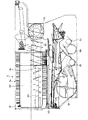
図3は、本実施形態に係るコンバインの内部構造を示す側面図である。図4は、本実施形態に係るコンバインの内部構造を示す平面図である。図3および図4に示すように、脱穀装置5は、穀稈搬送装置10により穀稈が後方に搬送される過程で、刈取装置7により刈り取った穀稈から穀粒を切離し、藁等の夾雑物と穀粒とを分離するものである。図3に示すように、脱穀装置5は、脱穀部5aと、脱穀部5aの下方に配置された選別部5bとを有する。図3および図4に示すように、脱穀部5aは、前部左側に配置された扱室5Iと、扱室5Iの右方に配置された第二処理室5Kと、第二処理室5Kの後方に配置された排塵処理室5Eとを含んで構成される。扱室5Iは、キャビン6の左方に位置し、扱室5Iには、前後方向に延在する回転軸を中心に回転可能な円柱形状の扱胴5Rが配置されている。扱胴5Rは、回転動作により、扱室5I内に搬送されてきた穀稈の穂先部から穀粒を脱粒する。なお、第二処理室5Kには二番処理胴5Hが、排塵処理室5Eには排塵処理胴5Dが、それぞれ前後方向に延在する回転軸を中心に回転可能に配置されている。
FIG. 3 is a side view showing the internal structure of the combine according to the present embodiment. FIG. 4 is a plan view showing the internal structure of the combine according to the present embodiment. As shown in FIG. 3 and FIG. 4, the threshing device 5 is a process in which cereals are conveyed backward by the cereal conveying device 10, and the grains are separated from the cereals harvested by the reaping device 7, so A thing and a grain are isolate | separated. As shown in FIG. 3, the threshing apparatus 5 includes a threshing unit 5a and a sorting unit 5b arranged below the threshing unit 5a. As shown in FIGS. 3 and 4, the threshing unit 5a includes a handling chamber 5I arranged on the left side of the front part, a second processing chamber 5K arranged on the right side of the handling chamber 5I, and a second processing chamber 5K. And a dust exhaust treatment chamber 5E disposed rearward. The handling chamber 5I is located on the left side of the cabin 6. In the handling chamber 5I, a cylindrical handling cylinder 5R that is rotatable about a rotation axis extending in the front-rear direction is disposed. The handling cylinder 5R sheds the grain from the tip of the cereal that has been conveyed into the handling chamber 5I by a rotating operation. A second processing cylinder 5H is disposed in the second processing chamber 5K, and a dust processing cylinder 5D is disposed in the dust processing chamber 5E so as to be rotatable about a rotation axis extending in the front-rear direction.
選別部5bは、扱室5Iの下方に揺動可能に配置された選別棚5Cと、選別棚5Cの下方空間にそれぞれ配置された唐箕5Fと、唐箕5Fの後方に配置された第2唐箕5Mと、一番回収部5Gおよび二番回収部5Jと、選別棚5Cの後方に配置された排塵ファン5Lとを含んで構成される。選別部5bは、脱穀部5aで脱粒された穀粒を含む被処理物(扱胴5Rが脱穀したもの)から夾雑物を除去して、穀粒を回収する。すなわち、選別棚5Cの揺動運動と、唐箕5Fおよび第2唐箕5Mによる選別風、および排塵ファン5Lによる吸引の作用とにより、脱穀部5aから送られてきた被処理物から穀粒を選別し、一番回収部5Gおよび二番回収部5Jで回収する。回収した穀粒は、グレンタンク8に搬送され、貯蔵される。なお、脱穀装置5を通過し、穀粒が扱ぎ取られた穀稈(排藁)は、穀稈搬送装置10の後方側に配置された図示しない排藁搬送装置によって、コンバイン1の後方側に配置されている排藁切断装置へ搬送される。排藁切断装置は、排藁搬送装置に投入された排藁を切断し、例えば、圃場に放出する。
The sorting unit 5b includes a sorting shelf 5C that is swingably disposed below the handling chamber 5I, a tang 5F that is disposed in a lower space of the sorting shelf 5C, and a second tang 5M that is disposed behind the tang 5F. And a first recovery unit 5G and a second recovery unit 5J, and a dust exhaust fan 5L disposed behind the sorting shelf 5C. The sorting unit 5b removes foreign substances from the object to be processed (the one that the handling cylinder 5R has threshed) including the grain threshed by the threshing unit 5a, and collects the grain. That is, the grains are selected from the workpieces sent from the threshing section 5a by the swinging movement of the sorting shelf 5C, the sorting wind by the Kara 5F and the second Kara 5M, and the suction action by the dust exhaust fan 5L. Then, the first collection unit 5G and the second collection unit 5J collect it. The recovered grain is transferred to the Glen tank 8 and stored. In addition, the cereal basket (removal) which passed the threshing apparatus 5 and the grain was handled is rear side of the combine 1 by the unrepresented waste transport apparatus arrange | positioned at the rear side of the cereal transport apparatus 10. It is conveyed to the waste cutting device arranged in the. The waste cutting device cuts the waste put into the waste transporting device and discharges it to the field, for example.
再び、図1および図2を参照し、キャビン6の後方側には、脱穀装置5が脱穀した穀粒を一時的に貯蔵するためのグレンタンク8が配置されている。グレンタンク8の後方側には、内部に貯蔵された穀粒を外部へ排出する穀粒排出オーガ9が設けられている。穀粒排出オーガ9は、グレンタンク8に接続された揚穀筒9aと、揚穀筒9aに接続された伸縮可能な搬送筒9bと、グレンタンク8、揚穀筒9aおよび搬送筒9bの内部に設けられた複数の螺旋軸とを有している。搬送筒9bには、穀粒を排出する排出口が設けられ、穀粒排出オーガ9は、搬送筒9bを適宜伸縮させつつ、昇降および旋回させることで、排出口を所定の場所に位置させる。そして、穀粒排出オーガ9は、複数の螺旋軸を回転させることで、グレンタンク8の内部から揚穀筒9aへ穀粒を搬送し、揚穀筒9aから搬送筒9bへ穀粒を搬送することで、搬送筒9bへ搬送された穀粒は、搬送筒9bに設けられた排出口を介して外部に排出される。
Again referring to FIGS. 1 and 2, on the rear side of the cabin 6, a Glen tank 8 for temporarily storing the grains threshed by the threshing device 5 is arranged. A grain discharge auger 9 is provided on the rear side of the grain tank 8 to discharge the grain stored therein to the outside. The grain discharge auger 9 includes an uncooked cylinder 9a connected to the glen tank 8, an extendable transfer cylinder 9b connected to the pulverized cylinder 9a, and the inside of the glen tank 8, the cereal cylinder 9a and the transfer cylinder 9b. And a plurality of helical shafts provided on the surface. The transport cylinder 9b is provided with a discharge port for discharging the grain, and the grain discharge auger 9 moves the transport cylinder 9b up and down as appropriate, and moves the discharge port at a predetermined place by turning it up and down. And the grain discharge auger 9 conveys a grain from the inside of the glen tank 8 to the whipping cylinder 9a by rotating a some helical shaft, and conveys a grain from the groining cylinder 9a to the conveyance cylinder 9b. Thereby, the grain conveyed to the conveyance cylinder 9b is discharged | emitted outside via the discharge port provided in the conveyance cylinder 9b.
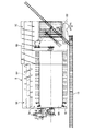
次に、図5および図6を参照して、穀稈搬送装置10について説明する。図5は、本実施形態に係るコンバインの内部構造を示す側面図である。図6は、本実施形態に係るコンバインの一部を示す側面図である。穀稈搬送装置10は、刈取装置7から脱穀装置5へ向けて刈り取った穀稈を搬送している。穀稈搬送装置10は、図2に示すグレンタンク8が配置されている側とは反対側、すなわち、左側部に配置されている。穀稈搬送装置10は、挟扼杆11(図1および図6参照)と、フィードチェン13(図4から図6参照)とを含む。穀稈搬送装置10は、刈取装置7によって刈り取った穀稈を、挟扼杆11とフィードチェン13との間に送り込む。フィードチェン13は、扱胴5Rの回転中心軸と交差する方向、かつ扱室5Iの一方側(左側)に配置される。挟扼杆11は、図示しないコイルスプリングによって、フィードチェン13側へ向けて付勢される。このような構造により、挟扼杵11は、穀稈にフィードチェン13へ向かう力を付与する。このため、挟扼杆11とフィードチェン13との間に送り込まれた穀稈は、挟扼杆11とフィードチェン13とに挟み込まれ、フィードチェン13によって脱穀装置5に搬送される。
Next, with reference to FIG. 5 and FIG. FIG. 5 is a side view showing the internal structure of the combine according to the present embodiment. FIG. 6 is a side view showing a part of the combine according to the present embodiment. The corn straw transporting device 10 transports the corn straw harvested from the reaping device 7 toward the threshing device 5. The grain feeder 10 is disposed on the opposite side to the side where the grain tank 8 shown in FIG. 2 is disposed, that is, on the left side. The cereal feeder 10 includes a pinch 11 (see FIGS. 1 and 6) and a feed chain 13 (see FIGS. 4 to 6). The corn straw transporting device 10 feeds the corn straw harvested by the reaping device 7 between the pinch 11 and the feed chain 13. The feed chain 13 is disposed in a direction intersecting with the rotation center axis of the handling cylinder 5R and on one side (left side) of the handling chamber 5I. The clamp 11 is urged toward the feed chain 13 by a coil spring (not shown). With such a structure, the scissors 11 imparts a force toward the feed chain 13 to the cereal. For this reason, the cereals fed between the culvert 11 and the feed chain 13 are sandwiched between the clinches 11 and the feed chain 13 and conveyed to the threshing device 5 by the feed chain 13.
本実施形態において、図6に示すように、フィードチェン13は、刈取装置7側における端部13Tが、挟扼杆11の刈取装置7側における端部11Tに比して長くなっている。このため、フィードチェン13は、刈取装置7側における端部13Tが露出した状態となっている。挟扼杆11の刈取装置7側における端部(上手側の部位)11Tには、露出するフィードチェン13の端部13Tを覆う規制部材14が設けられている。この規制部材14は、挟扼杆11の端部11Tを中心として、後述する手扱ぎ作業を許容する開放位置L1と、手扱ぎ作業を規制する規制位置L2との間で回動自在となるように、挟扼杆11の端部11Tに取り付けられている。このため、手扱ぎ作業時には、規制部材14を規制位置L2から開放位置L1へ回動させ、一方で、非手扱ぎ作業時には、規制部材14を開放位置L1から規制位置L2へ回動させる。これにより、非手扱ぎ作業時には、規制部材14がフィードチェン13を覆うことになることから、挟扼杆11とフィードチェン13との間に穀稈以外の異物が挟み込まれるおそれを低くでき、非手扱ぎ作業時の安全性を向上させることができる。なお、規制部材14周りには、規制部材14の開放位置L1と規制位置L2とを検出可能な規制部材位置検出センサ172が設けられている。
In the present embodiment, as shown in FIG. 6, the feed chain 13 has an end portion 13T on the mowing device 7 side that is longer than an end portion 11T on the mowing device 7 side of the pinch 11. For this reason, the feed chain 13 is in a state in which the end portion 13T on the cutting device 7 side is exposed. A regulating member 14 that covers the exposed end portion 13T of the feed chain 13 is provided at an end portion (upper side portion) 11T of the clip bar 11 on the cutting device 7 side. The restricting member 14 is rotatable around an end portion 11T of the pinch 11 between an open position L1 that permits a handling operation described later and a restricting position L2 that restricts the handling operation. It is attached to the edge part 11T of the clip 11 so that it may become. For this reason, during the handling operation, the regulating member 14 is rotated from the regulating position L2 to the open position L1, while during the non-handling operation, the regulating member 14 is rotated from the open position L1 to the regulating position L2. . Thereby, at the time of non-handling work, since the regulating member 14 covers the feed chain 13, it is possible to reduce the possibility that foreign matters other than the cereals are caught between the pinch 11 and the feed chain 13. Safety during non-handling work can be improved. A restricting member position detection sensor 172 capable of detecting the opening position L1 and the restricting position L2 of the restricting member 14 is provided around the restricting member 14.
ここで、コンバイン1は、通常、走行装置3により走行しながら、刈取装置7が刈り取った穀稈を脱穀装置5で処理する。一方で、コンバイン1は、走行を停止した状態で、作業者が手刈りした穀稈をフィードチェン13によって脱穀装置5へ供給して処理する手扱ぎ処理(手扱ぎ作業)を行う場合がある。この手扱ぎ作業では、作業者が、手刈りした穀稈をフィードチェン13に供給することで、穀稈が挟扼杆11とフィードチェン13との間に挟まれて搬送されながら脱穀装置5に供給される。そして、脱穀装置5に供給された穀稈は、脱穀装置5により脱穀される。
Here, the combine 1 normally processes the cereals harvested by the reaping device 7 with the threshing device 5 while traveling by the traveling device 3. On the other hand, the combine 1 may perform a hand handling process (hand handling work) in which the cedar harvested by the operator is supplied to the threshing device 5 by the feed chain 13 in a state where traveling is stopped. is there. In this hand-handling operation, the worker supplies the hand-harvested cereals to the feed chain 13 so that the cereals are sandwiched between the pinch 11 and the feed chain 13 and conveyed. To be supplied. The cereal meal supplied to the threshing device 5 is threshed by the threshing device 5.
ここで、図7を参照して、エンジン20から穀稈搬送装置10のフィードチェン13に至る動力伝達経路について説明する。図7は、本実施形態に係るコンバインの動力伝達経路の一部を示す模式図である。
Here, with reference to FIG. 7, the power transmission path | route from the engine 20 to the feed chain 13 of the grain feeder 10 is demonstrated. FIG. 7 is a schematic diagram showing a part of the power transmission path of the combine according to the present embodiment.
エンジン20には、出力軸20Sが設けられ、出力軸20Sには、複数のエンジン出力プーリ20Pが取り付けられている。なお、複数のエンジン出力プーリ20Pからは、走行装置3、刈取装置7、脱穀装置5、穀粒排出オーガ9および穀稈搬送装置10を駆動するための動力が出力される。なお、図7では、複数のエンジン出力プーリ20Pから脱穀装置5および穀稈搬送装置10を駆動するための動力が出力される動力伝達経路について図示する。一方で、図7では、複数のエンジン出力プーリ20Pから走行装置3、刈取装置7および穀粒排出オーガ9を駆動するための動力が出力される動力伝達経路についての図示は省略する。
The engine 20 is provided with an output shaft 20S, and a plurality of engine output pulleys 20P are attached to the output shaft 20S. The plurality of engine output pulleys 20 </ b> P output power for driving the traveling device 3, the reaping device 7, the threshing device 5, the grain discharge auger 9, and the culm conveying device 10. In addition, in FIG. 7, the motive power transmission path | route in which the motive power for driving the threshing apparatus 5 and the cereal conveyance apparatus 10 is output from the some engine output pulley 20P is illustrated. On the other hand, in FIG. 7, illustration of a power transmission path through which power for driving the traveling device 3, the reaping device 7, and the grain discharge auger 9 is output from the plurality of engine output pulleys 20 </ b> P is omitted.
複数(本実施形態では、例えば3つ)のエンジン出力プーリ20Pからは、脱穀装置5および穀稈搬送装置10を駆動するための動力が出力される。コンバイン1は、脱穀装置5へ動力を伝達するための脱穀動力伝達シャフト38を有する。脱穀動力伝達シャフト38には、一端側(図示左側)から順に、複数(本実施形態では、例えば3つ)の入力プーリ38a、処理胴出力プーリ38b、複数(本実施形態では、例えば3つ)の扱胴出力プーリ38c、回収部出力プーリ38d、および唐箕出力プーリ38eが取り付けられている。
The motive power for driving the threshing device 5 and the cereal conveying device 10 is output from a plurality of (for example, three in this embodiment) engine output pulleys 20P. The combine 1 has a threshing power transmission shaft 38 for transmitting power to the threshing device 5. In the threshing power transmission shaft 38, a plurality (for example, three in this embodiment) of input pulleys 38a, a processing cylinder output pulley 38b, and a plurality of (for example, three in the present embodiment) are sequentially arranged from one end side (the left side in the figure). A cylinder output pulley 38c, a recovery unit output pulley 38d, and a tang output pulley 38e are attached.
複数のエンジン出力プーリ20Pと複数の入力プーリ38aとには、複数(本実施形態では、例えば3つ)の第1伝達ベルト37が掛け回されている。第1伝達ベルト37は無端のベルトである。このため、エンジン20から発生した動力は、各エンジン出力プーリ20Pと各第1伝達ベルト37と各入力プーリ38aとを介して、脱穀動力伝達シャフト38に伝達される。
A plurality of (for example, three in this embodiment) first transmission belts 37 are wound around the plurality of engine output pulleys 20P and the plurality of input pulleys 38a. The first transmission belt 37 is an endless belt. Therefore, the power generated from the engine 20 is transmitted to the threshing power transmission shaft 38 via each engine output pulley 20P, each first transmission belt 37, and each input pulley 38a.
各エンジン出力プーリ20Pと各入力プーリ38aとの間には、脱穀クラッチ81が設けられている。脱穀クラッチ81を接続すると、エンジン出力プーリ20Pと入力プーリ38aとの間で動力が伝達され、脱穀クラッチ81の接続を解除すると、エンジン出力プーリ20Pと入力プーリ38aとの間における動力の伝達が遮断される。
A threshing clutch 81 is provided between each engine output pulley 20P and each input pulley 38a. When the threshing clutch 81 is connected, power is transmitted between the engine output pulley 20P and the input pulley 38a. When the threshing clutch 81 is released, power transmission between the engine output pulley 20P and the input pulley 38a is cut off. Is done.
二番処理胴5Hおよび排塵処理胴5Dは、処理胴出力プーリ38bから伝達される動力で駆動される。処理胴出力プーリ38bには、無端の第2伝達ベルト60を介して、処理胴駆動プーリ61aが連結されている。処理胴駆動プーリ61aは、処理胴駆動シャフト61の一端部に取り付けられている。処理胴駆動シャフト61の他端部には、第1傘歯車61bが取り付けられており、第1傘歯車61bは、第2傘歯車62aと噛み合っている。第2傘歯車62aは、処理胴回転シャフト62に取り付けられ、処理胴回転シャフト62には、二番処理胴5Hおよび排塵処理胴5Dが取り付けられている。このため、脱穀動力伝達シャフト38に伝達されたエンジン20の動力は、処理胴出力プーリ38b、第2伝達ベルト60、処理胴駆動プーリ61a、処理胴駆動シャフト61、第1傘歯車61b、第2傘歯車62aおよび処理胴回転シャフト62を介して、二番処理胴5Hおよび排塵処理胴5Dに伝達されることで、二番処理胴5Hおよび排塵処理胴5Dを回転させる。これにより、二番処理胴5Hおよび排塵処理胴5Dは、エンジン20の動力が直接伝達されるため、コンバイン1の走行速度に関わらず一定の速度(回転速度)で駆動される。
The second processing cylinder 5H and the dust processing cylinder 5D are driven by the power transmitted from the processing cylinder output pulley 38b. A processing cylinder driving pulley 61a is connected to the processing cylinder output pulley 38b via an endless second transmission belt 60. The processing cylinder driving pulley 61 a is attached to one end of the processing cylinder driving shaft 61. A first bevel gear 61b is attached to the other end of the processing cylinder drive shaft 61, and the first bevel gear 61b meshes with the second bevel gear 62a. The second bevel gear 62a is attached to the processing cylinder rotating shaft 62, and the second processing cylinder 5H and the dust exhausting processing cylinder 5D are attached to the processing cylinder rotating shaft 62. Therefore, the power of the engine 20 transmitted to the threshing power transmission shaft 38 is the processing cylinder output pulley 38b, the second transmission belt 60, the processing cylinder driving pulley 61a, the processing cylinder driving shaft 61, the first bevel gear 61b, the second By being transmitted to the second processing cylinder 5H and the dust removal processing cylinder 5D via the bevel gear 62a and the processing cylinder rotation shaft 62, the second processing cylinder 5H and the dust processing cylinder 5D are rotated. As a result, the power of the engine 20 is directly transmitted to the second processing cylinder 5H and the dust exhausting processing cylinder 5D, and thus is driven at a constant speed (rotational speed) regardless of the traveling speed of the combine 1.
扱胴5Rは、扱胴出力プーリ38cから伝達される動力で駆動される。扱胴出力プーリ38cには、無端の第3伝達ベルト63を介して、扱胴駆動プーリ64aが連結されている。扱胴駆動プーリ64aは、第1扱胴駆動シャフト64の一端部に取り付けられている。第1扱胴駆動シャフト64の他端部には、第1減速ギヤ64bが取り付けられており、第1減速ギヤ64bは、第2減速ギヤ65aと噛み合っている。第2減速ギヤ65aは、第2扱胴駆動シャフト65の一端部に取り付けられている。第2扱胴駆動シャフト65の他端部には、第3傘歯車65bが取り付けられており、第3傘歯車65bは、第4傘歯車66aと噛み合っている。第4傘歯車66aは、扱胴回転シャフト66に取り付けられ、扱胴回転シャフト66には、扱胴5Rが取り付けられている。このため、脱穀動力伝達シャフト38に伝達されたエンジン20の動力は、扱胴出力プーリ38c、第3伝達ベルト63、扱胴駆動プーリ64a、第1扱胴駆動シャフト64、第1減速ギヤ64b、第2減速ギヤ65a、第2扱胴駆動シャフト65、第3傘歯車65b、第4傘歯車66aおよび扱胴回転シャフト66を介して、扱胴5Rに伝達されることで、扱胴5Rを回転させる。これにより、扱胴5Rも、エンジン20の動力が直接伝達されるため、コンバイン1の走行速度に関わらず一定の速度(回転速度)で駆動される。
The handling cylinder 5R is driven by the power transmitted from the handling cylinder output pulley 38c. A handling cylinder driving pulley 64 a is connected to the handling cylinder output pulley 38 c via an endless third transmission belt 63. The handling cylinder drive pulley 64 a is attached to one end of the first handling cylinder drive shaft 64. A first reduction gear 64b is attached to the other end of the first barrel drive shaft 64, and the first reduction gear 64b meshes with the second reduction gear 65a. The second reduction gear 65 a is attached to one end portion of the second barrel drive shaft 65. A third bevel gear 65b is attached to the other end portion of the second barrel drive shaft 65, and the third bevel gear 65b meshes with the fourth bevel gear 66a. The fourth bevel gear 66 a is attached to the handling cylinder rotation shaft 66, and the handling cylinder 5 </ b> R is attached to the handling cylinder rotation shaft 66. For this reason, the power of the engine 20 transmitted to the threshing power transmission shaft 38 is the handling cylinder output pulley 38c, the third transmission belt 63, the handling cylinder drive pulley 64a, the first handling cylinder drive shaft 64, the first reduction gear 64b, The handle 5R is rotated by being transmitted to the handle cylinder 5R via the second reduction gear 65a, the second handle drive shaft 65, the third bevel gear 65b, the fourth bevel gear 66a, and the handle rotation shaft 66. Let Thereby, since the power of the engine 20 is directly transmitted, the handling cylinder 5R is also driven at a constant speed (rotational speed) regardless of the traveling speed of the combine 1.
唐箕5Fは、唐箕出力プーリ38eから伝達される動力で駆動される。唐箕出力プーリ38eには、無端の第4伝達ベルト67を介して、唐箕駆動プーリ68aが連結されている。唐箕駆動プーリ68aは、唐箕回転シャフト68の一端部に取り付けられている。唐箕回転シャフト68には、唐箕変速機構69を介して、唐箕5Fが取り付けられている。このため、脱穀動力伝達シャフト38に伝達されたエンジン20の動力は、唐箕出力プーリ38e、第4伝達ベルト67、唐箕駆動プーリ68a、唐箕回転シャフト68、唐箕変速機構69を介して、唐箕5Fに伝達されることで、唐箕5Fを回転させる。これにより、唐箕5Fは、エンジン20の動力が唐箕変速機構69を介して伝達されるため、所定の速度(回転速度)で駆動される。
The Kara 5F is driven by the power transmitted from the Kara output pulley 38e. A tang drive pulley 68 a is connected to the tang output pulley 38 e through an endless fourth transmission belt 67. The tang drive pulley 68 a is attached to one end of the tang drive shaft 68. A Kara 5F is attached to the Kara rotary shaft 68 via a Kara transmission mechanism 69. For this reason, the power of the engine 20 transmitted to the threshing power transmission shaft 38 is transmitted to the Kara 5F via the Kara output pulley 38e, the fourth transmission belt 67, the Kara drive pulley 68a, the Kara rotary shaft 68, and the Kara transmission mechanism 69. By being transmitted, the Kara 5F is rotated. Thereby, the power of the engine 20 is transmitted at the predetermined speed (rotational speed) because the power of the engine 20 is transmitted through the data transmission mechanism 69.
一番回収部5Gおよび二番回収部5Jは、回収部出力プーリ38dから伝達される動力で駆動される。回収部出力プーリ38dには、無端の第5伝達ベルト90を介して、一番回収部駆動プーリ91aおよび二番回収部駆動プーリ92aが連結されている。一番回収部駆動プーリ91aは、一番回収部5Gを駆動するための一番回収部駆動シャフト91に取り付けられている。二番回収部駆動プーリ92aは、二番回収部5Jを駆動するための二番回収部駆動シャフト92に取り付けられている。このため、脱穀動力伝達シャフト38に伝達されたエンジン20の動力は、回収部出力プーリ38d、第5伝達ベルト90、一番回収部駆動プーリ91aおよび一番回収部駆動シャフト91を介して、一番回収部5Gに伝達されることで、一番回収部5Gを駆動させる。また、脱穀動力伝達シャフト38に伝達されたエンジン20の動力は、回収部出力プーリ38d、第5伝達ベルト90、二番回収部駆動プーリ92a、二番回収部駆動シャフト92を介して、二番回収部5Jに伝達されることで、二番回収部5Jを駆動させる。
The first recovery unit 5G and the second recovery unit 5J are driven by the power transmitted from the recovery unit output pulley 38d. The first recovery unit drive pulley 91a and the second recovery unit drive pulley 92a are connected to the recovery unit output pulley 38d via an endless fifth transmission belt 90. The first recovery unit drive pulley 91a is attached to a first recovery unit drive shaft 91 for driving the first recovery unit 5G. The second recovery portion drive pulley 92a is attached to a second recovery portion drive shaft 92 for driving the second recovery portion 5J. For this reason, the power of the engine 20 transmitted to the threshing power transmission shaft 38 is transmitted through the recovery unit output pulley 38d, the fifth transmission belt 90, the first recovery unit drive pulley 91a, and the first recovery unit drive shaft 91. The first collecting unit 5G is driven by being transmitted to the number collecting unit 5G. Further, the power of the engine 20 transmitted to the threshing power transmission shaft 38 is the second through the recovery part output pulley 38d, the fifth transmission belt 90, the second recovery part drive pulley 92a, and the second recovery part drive shaft 92. The second collection unit 5J is driven by being transmitted to the collection unit 5J.
また、一番回収部駆動プーリ91aと二番回収部駆動プーリ92aとの間には、第2唐箕駆動プーリ93aが設けられ、第2唐箕駆動プーリ93aは、第5伝達ベルト90に連結されている。第2唐箕駆動プーリ93aは、第2唐箕回転シャフト93に取り付けられ、第2唐箕回転シャフト93には、第2唐箕5Mが取り付けられている。このため、脱穀動力伝達シャフト38に伝達されたエンジン20の動力は、回収部出力プーリ38d、第5伝達ベルト90、第2唐箕駆動プーリ93aおよび第2唐箕回転シャフト93を介して、第2唐箕5Mに伝達されることで、第2唐箕5Mを回転させる。
Further, a second tang drive pulley 93a is provided between the first recovery portion drive pulley 91a and the second recovery portion drive pulley 92a, and the second tang drive pulley 93a is connected to the fifth transmission belt 90. Yes. The second hot spring driving pulley 93a is attached to the second hot spring rotary shaft 93, and the second hot spring rotary shaft 93 is attached to the second hot spring rotary shaft 93M. For this reason, the motive power of the engine 20 transmitted to the threshing power transmission shaft 38 is supplied to the second tangs through the recovery unit output pulley 38d, the fifth transmission belt 90, the second tangs drive pulley 93a, and the second tangs rotation shaft 93. By being transmitted to 5M, the second Kara 5M is rotated.
ここで、一番回収部駆動シャフト91には、搬送駆動プーリ91bが取り付けられ、搬送駆動プーリ91bからは、穀稈搬送装置10を駆動するための動力が取り出される。搬送駆動プーリ91bは、第6伝達ベルト92を介して、ギヤボックス100の変速入力プーリ101aに連結されている。
Here, a conveyance drive pulley 91b is attached to the first recovery unit drive shaft 91, and power for driving the cereal conveyance device 10 is taken out from the conveyance drive pulley 91b. The transport drive pulley 91 b is connected to the transmission input pulley 101 a of the gear box 100 through the sixth transmission belt 92.
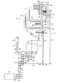
次に、図7から図9を参照して、ギヤボックス100について説明する。図8は、本実施形態に係るコンバインのギヤボックスの内部構造を示す側面図である。図9は、本実施形態に係るコンバインのギヤボックスの内部構造を示す平面図である。このギヤボックス100は、エンジン20からの動力を変速してフィードチェン13へ向けて出力するフィードチェン変速装置として機能すると共に、エンジン20からの動力を遮断可能なクラッチとして機能する。
Next, the gear box 100 will be described with reference to FIGS. FIG. 8 is a side view showing the internal structure of the combine gearbox according to the present embodiment. FIG. 9 is a plan view showing the internal structure of the combine gearbox according to the present embodiment. The gear box 100 functions as a feed chain transmission that shifts the power from the engine 20 and outputs it to the feed chain 13 and also functions as a clutch that can cut off the power from the engine 20.
ギヤボックス100は、第6伝達ベルト92に連結された変速入力プーリ101aを有し、変速入力プーリ101aは、ギヤボックス入力軸101の一端部に取り付けられている。ギヤボックス入力軸101の他端部には、入力ギヤ101bが取り付けられており、入力ギヤ101bは、排塵ファン出力ギヤ102aと噛み合っている。排塵ファン出力ギヤ102aは、排塵ファン回転シャフト102に取り付けられ、排塵ファン回転シャフト102には、排塵ファン5Lが取り付けられている。このため、一番回収部駆動シャフト91に伝達されたエンジン20の動力は、搬送駆動プーリ91b、第6伝達ベルト92、変速入力プーリ101a、ギヤボックス入力軸101、入力ギヤ101b、排塵ファン出力ギヤ102aおよび排塵ファン回転シャフト102を介して、排塵ファン5Lに伝達されることで、排塵ファン5Lを回転させる。これにより、排塵ファン5Lも、エンジン20の動力が直接伝達されるため、コンバイン1の走行速度に関わらず一定の速度(回転速度)で駆動される。
The gear box 100 includes a transmission input pulley 101 a connected to the sixth transmission belt 92, and the transmission input pulley 101 a is attached to one end of the gear box input shaft 101. An input gear 101b is attached to the other end portion of the gear box input shaft 101, and the input gear 101b meshes with the dust exhaust fan output gear 102a. The dust exhaust fan output gear 102 a is attached to the dust exhaust fan rotating shaft 102, and the dust exhaust fan 5 </ b> L is attached to the dust exhaust fan rotating shaft 102. Therefore, the power of the engine 20 transmitted to the recovery unit drive shaft 91 is the conveyance drive pulley 91b, the sixth transmission belt 92, the transmission input pulley 101a, the gear box input shaft 101, the input gear 101b, and the dust fan output. The dust exhaust fan 5L is rotated by being transmitted to the dust exhaust fan 5L via the gear 102a and the dust exhaust fan rotating shaft 102. Accordingly, the dust exhaust fan 5L is also driven at a constant speed (rotational speed) regardless of the traveling speed of the combine 1 because the power of the engine 20 is directly transmitted.
また、排塵ファン出力ギヤ102aは、変速入力ギヤ103aと噛み合っている。変速入力ギヤ103aは、変速軸103の一端部に取り付けられている。この変速軸103には、高速側伝動ギヤ103bと低速側伝動ギヤ103cとが回転自在に取り付けられている。高速側伝動ギヤ103bは、変速入力ギヤ103a側に設けられ、低速側伝動ギヤ103cは、高速側伝動ギヤ103bを挟んで、変速入力ギヤ103aの反対側に設けられている。高速側伝動ギヤ103bと低速側伝動ギヤ103cとの間の変速軸103には、移動体103dが設けられ、移動体103dは、変速軸103と一体的に回転するように取り付けられる一方で、変速軸103の軸方向に移動可能となっている。高速側伝動ギヤ103bの軸方向の移動体103dと対向する面には、高速側クラッチ爪104が設けられ、低速側伝動ギヤ103cの軸方向の移動体103dと対向する面には、低速側クラッチ爪105が設けられる。また、移動体103dの軸方向の高速側伝動ギヤ103bと対向する面には、高速側クラッチ爪104に係合可能な第1クラッチ爪106が設けられ、移動体103dの軸方向の低速側伝動ギヤ103cと対向する面には、低速側クラッチ爪105に係合可能な第2クラッチ爪107が設けられる。
The dust exhaust fan output gear 102a meshes with the transmission input gear 103a. The transmission input gear 103 a is attached to one end of the transmission shaft 103. A high-speed transmission gear 103b and a low-speed transmission gear 103c are rotatably attached to the transmission shaft 103. The high speed side transmission gear 103b is provided on the transmission input gear 103a side, and the low speed side transmission gear 103c is provided on the opposite side of the transmission input gear 103a with the high speed side transmission gear 103b interposed therebetween. The speed change shaft 103 between the high speed side transmission gear 103b and the low speed side transmission gear 103c is provided with a moving body 103d, and the moving body 103d is attached to rotate integrally with the speed change shaft 103, while the speed change gear 103b. The shaft 103 can move in the axial direction. A high speed side clutch pawl 104 is provided on a surface of the high speed side transmission gear 103b facing the axial moving body 103d, and a low speed side clutch is provided on the surface of the low speed side transmission gear 103c facing the axial moving body 103d. A nail 105 is provided. Further, a first clutch pawl 106 that can be engaged with the high-speed side clutch pawl 104 is provided on a surface of the moving body 103d facing the high-speed side transmission gear 103b in the axial direction, and the low-speed side transmission in the axial direction of the mobile body 103d is provided. A second clutch pawl 107 that can be engaged with the low-speed clutch pawl 105 is provided on the surface facing the gear 103c.
このため、移動体103dが高速側伝動ギヤ103b側の高速側変速位置に移動すると、高速側クラッチ爪104と第1クラッチ爪106とが係合状態となる一方で、低速側クラッチ爪105と第2クラッチ爪107とが非係合状態となり、高速側伝動ギヤ103bは、移動体103dおよび変速軸103と一体となって回転する。一方で、移動体103dが低速側伝動ギヤ103c側の低速側変速位置に移動すると、低速側クラッチ爪105と第2クラッチ爪107とが係合状態となる一方で、高速側クラッチ爪104と第1クラッチ爪106とが非係合状態となり、低速側伝動ギヤ103cは、移動体103dおよび変速軸103と一体となって回転する。なお、移動体103dが高速側変速位置と低速側変速位置との間の中立位置に位置すると、移動体103dの第1クラッチ爪106および第2クラッチ爪107は、高速側クラッチ爪104および低速側クラッチ爪105と非係合状態となるため、変速軸103からの動力は、高速側伝動ギヤ103bおよび低速側伝動ギヤ103cへ伝達されずに遮断される。
For this reason, when the moving body 103d moves to the high speed side shift position on the high speed side transmission gear 103b side, the high speed side clutch pawl 104 and the first clutch pawl 106 are engaged, while the low speed side clutch pawl 105 and the first clutch pawl 105 are engaged. The two-clutch pawl 107 is disengaged, and the high-speed transmission gear 103b rotates integrally with the moving body 103d and the transmission shaft 103. On the other hand, when the moving body 103d moves to the low speed side shift position on the low speed side transmission gear 103c side, the low speed side clutch pawl 105 and the second clutch pawl 107 are engaged, while the high speed side clutch pawl 104 and the first clutch pawl 104 The one clutch pawl 106 is disengaged, and the low-speed transmission gear 103 c rotates integrally with the moving body 103 d and the transmission shaft 103. When the moving body 103d is positioned at a neutral position between the high speed side shifting position and the low speed side shifting position, the first clutch pawl 106 and the second clutch pawl 107 of the moving body 103d are connected to the high speed side clutch pawl 104 and the low speed side shifting position. Since the clutch pawl 105 is not engaged, the power from the transmission shaft 103 is cut off without being transmitted to the high speed transmission gear 103b and the low speed transmission gear 103c.
上記の移動体103dは、シフタアーム109を介してシフタ軸108に連結されており、シフタ軸108が回転することによって、変速軸103の軸方向に沿って、移動体103dを、高速側変速位置、中立位置、または低速側変速位置へ移動させる。このシフタ軸108は、変速ロッド110を介して変速用モータ111に接続されている。このため、変速用モータ111を動力源として、変速ロッド110を介してシフタ軸108を回転させることにより、移動体103dを所定の位置へ移動させることが可能となる。
The moving body 103d is connected to the shifter shaft 108 via the shifter arm 109. When the shifter shaft 108 rotates, the moving body 103d is moved along the axial direction of the transmission shaft 103 to the high speed side shift position, Move to the neutral position or low-speed side shift position. The shifter shaft 108 is connected to a speed change motor 111 via a speed change rod 110. Therefore, it is possible to move the moving body 103d to a predetermined position by rotating the shifter shaft 108 via the speed change rod 110 using the speed change motor 111 as a power source.
また、このシフタ軸108は、移動体103dが中立位置へ移動するように、クラッチアーム121により強制的に移動可能に構成されている。シフタ軸108は、軸方向の一方側(図示上側)の端部に、軸方向に直交する直交方向に突出する突起部124が設けられている。また、クラッチアーム121には、突起部124に嵌り込む溝部125が設けられている。クラッチアーム121は、フィードチェンクラッチモータ126に接続されている。このため、フィードチェンクラッチモータ126を動力源として、クラッチアーム121を所定の方向に移動させることで、クラッチアーム121の溝部125に、シフタ軸108の突起部124を嵌め込むことで、移動体103dが中立位置へ移動するように、シフタ軸108を強制的に回転させる。
The shifter shaft 108 is configured to be forcibly moved by the clutch arm 121 so that the moving body 103d moves to the neutral position. The shifter shaft 108 is provided with a protruding portion 124 that protrudes in an orthogonal direction orthogonal to the axial direction at one end (upper side in the drawing) in the axial direction. In addition, the clutch arm 121 is provided with a groove 125 that fits into the protrusion 124. The clutch arm 121 is connected to a feed chain clutch motor 126. Therefore, by moving the clutch arm 121 in a predetermined direction using the feed chain clutch motor 126 as a power source, the projecting portion 124 of the shifter shaft 108 is fitted into the groove portion 125 of the clutch arm 121, thereby moving the moving body 103d. The shifter shaft 108 is forcibly rotated so as to move to the neutral position.
上記の高速側伝動ギヤ103bは、高速側出力ギヤ112aと噛み合っている。また、上記の低速側伝動ギヤ103cは、低速側出力ギヤ112bと噛み合っている。高速側出力ギヤ112aおよび低速側出力ギヤ112bは、ギヤボックス出力軸113に一体に設けられている。このため、高速側出力ギヤ112aまたは低速側出力ギヤ112bに動力が伝達されることで、ギヤボックス出力軸113が回転する。
The high speed side transmission gear 103b meshes with the high speed side output gear 112a. The low-speed transmission gear 103c is meshed with the low-speed output gear 112b. The high speed side output gear 112 a and the low speed side output gear 112 b are integrally provided on the gear box output shaft 113. For this reason, the power is transmitted to the high-speed output gear 112a or the low-speed output gear 112b, whereby the gear box output shaft 113 rotates.
上記のように構成されたギヤボックス100のギヤボックス出力軸113には、フィードチェン駆動プーリ113aが設けられている。フィードチェン駆動プーリ113aには、フィードチェン13が巻き掛けられている。このため、ギヤボックス100のギヤボックス入力軸101に伝達されたエンジン20の動力は、ギヤボックス100において変速され、変速された動力は、ギヤボックス出力軸113からフィードチェン13に伝達されることで、フィードチェン13を駆動(周回)させる。
The gear box output shaft 113 of the gear box 100 configured as described above is provided with a feed chain drive pulley 113a. The feed chain 13 is wound around the feed chain drive pulley 113a. For this reason, the power of the engine 20 transmitted to the gear box input shaft 101 of the gear box 100 is shifted in the gear box 100, and the shifted power is transmitted from the gear box output shaft 113 to the feed chain 13. Then, the feed chain 13 is driven (circulated).
上記のように構成されたコンバイン1は、制御装置150によって制御される。図10を参照し、制御装置150について説明する。図10は、本実施形態に係るコンバインの制御系に関するブロック図である。制御装置150には、操作装置6Cおよび各種センサが接続され、操作装置6Cからの操作入力および各種センサから入力される検出結果に基づいて、エンジン20、走行装置3、脱穀装置5、刈取装置7および穀粒排出オーガ9を制御する。
The combine 1 configured as described above is controlled by the control device 150. The control device 150 will be described with reference to FIG. FIG. 10 is a block diagram relating to a combine control system according to the present embodiment. The control device 150 is connected to the operation device 6C and various sensors. Based on the operation input from the operation device 6C and the detection results input from the various sensors, the engine 20, the traveling device 3, the threshing device 5, and the reaping device 7 are connected. And controls the grain discharge auger 9.
具体的に、図10に示すように、制御装置150には、エンジン自動調整スイッチ161と、脱穀クラッチ検出センサ162と、脱穀用ポテンショメーター163と、走行用ポテンショメーター164と、車速センサ165と、駐車ブレーキセンサ166と、手扱ぎスイッチ167と、緊急停止スイッチ168(緊急停止操作部)と、搬送穀稈検出センサ169(第1穀稈検出センサ)と、刈取り穀稈検出センサ170(第2穀稈検出センサ)と、刈取駆動状態検出センサ171と、規制部材位置検出センサ172と、選別棚5Cの流量センサ173と、排藁層厚センサ174と、搬送穀稈層厚センサ175と、が接続されている。また、制御装置150には、モニタ6Dと、エンジン20と、変速用モータ111と、フィードチェンクラッチモータ126と、手扱ぎモードランプ190と、唐箕モータ191と、シーブモータ192と、刈取クラッチモータ193と、警報ブザー195と、主電源スイッチ196と、が接続されている。
Specifically, as shown in FIG. 10, the control device 150 includes an engine automatic adjustment switch 161, a threshing clutch detection sensor 162, a threshing potentiometer 163, a travel potentiometer 164, a vehicle speed sensor 165, and a parking brake. A sensor 166, a hand switch 167, an emergency stop switch 168 (emergency stop operation unit), a transported culm detection sensor 169 (first culm detection sensor), and a cutting culm detection sensor 170 (second culm) Detection sensor), cutting drive state detection sensor 171, restriction member position detection sensor 172, flow rate sensor 173 of sorting shelf 5C, waste layer thickness sensor 174, and transported culm layer thickness sensor 175 are connected. ing. Further, the control device 150 includes a monitor 6D, an engine 20, a speed change motor 111, a feed chain clutch motor 126, a handling mode lamp 190, a red pepper motor 191, a sheave motor 192, and a cutting clutch motor 193. The alarm buzzer 195 and the main power switch 196 are connected.
エンジン自動調整スイッチ161は、操作装置6Cの操作パネルに設けられ、コンバイン1の駆動状態に応じて、エンジン20の定格回転数(定格回転速度)を調整するために入切操作されるスイッチである。つまり、制御装置150は、エンジン自動調整スイッチ161の入操作(ON操作)を検出すると、エンジン20の定格回転数を自動で調整する一方で、エンジン自動調整スイッチ161の切操作(OFF操作)を検出すると、エンジン20の定格回転数の自動調整を解除する。
The engine automatic adjustment switch 161 is a switch that is provided on the operation panel of the operating device 6C and is turned on and off to adjust the rated speed (rated speed) of the engine 20 in accordance with the drive state of the combine 1. . That is, when the control device 150 detects an on-operation (ON operation) of the engine automatic adjustment switch 161, the control device 150 automatically adjusts the rated rotational speed of the engine 20, while turning off the engine automatic adjustment switch 161 (OFF operation). When detected, the automatic adjustment of the rated speed of the engine 20 is canceled.
脱穀クラッチ検出センサ162は、脱穀クラッチ81による接続および接続解除を検出している。脱穀用ポテンショメーター163は、脱穀操作レバーの操作位置を検出している。脱穀操作レバーは、刈取位置および脱穀位置を含む所定の操作位置となるように操作される。刈取位置は、刈取装置7による穀稈の刈り取りを行うと共に脱穀装置5による脱穀を行うための操作位置となっている。脱穀位置は、脱穀装置5による脱穀を行うための操作位置となっている。
The threshing clutch detection sensor 162 detects connection and disconnection by the threshing clutch 81. The threshing potentiometer 163 detects the operation position of the threshing operation lever. The threshing operation lever is operated so as to be a predetermined operation position including a cutting position and a threshing position. The reaping position is an operation position for reaping the culm with the reaping device 7 and threshing with the threshing device 5. The threshing position is an operation position for performing threshing by the threshing device 5.
走行用ポテンショメーター164は、走行操作レバー6Hの操作位置を検出している。走行操作レバー6Hは、エンジン20の動力を変速する図示しない油圧式無段変速機を操作するためのレバーである。油圧式無段変速機は、HST(Hydro Static Transmission)と呼ばれる静油圧式の無段変速機として構成されている。走行操作レバー6Hは、前進位置、後退位置および中立位置を含む所定の操作位置となるように操作される。前進位置は、コンバイン1を前進させるための操作位置となっており、前進位置としては、コンバイン1の車速を低速とする低速位置、コンバイン1の車速を中速とする中速位置、およびコンバイン1の車速を高速とする高速位置等がある。後退位置は、コンバイン1を後退させるための操作位置となっている。中立位置は、コンバイン1の走行を停止させるための操作位置となっている。このため、走行操作レバー6Hが前進位置、中立位置および後退位置等に操作されることで、油圧式無段変速機は、エンジン20の動力を、コンバイン1が前進方向に駆動する動力として出力したり、コンバイン1の走行を停止させる制動力として出力したり、コンバイン1が後退方向に駆動する動力として出力可能となっている。
The travel potentiometer 164 detects the operation position of the travel operation lever 6H. The travel operation lever 6H is a lever for operating a hydraulic continuously variable transmission (not shown) that shifts the power of the engine 20. The hydraulic continuously variable transmission is configured as a hydrostatic continuously variable transmission called HST (Hydro Static Transmission). The travel operation lever 6H is operated so as to be a predetermined operation position including a forward position, a reverse position, and a neutral position. The forward position is an operation position for moving the combine 1 forward. As the forward position, the low speed position where the combine 1 vehicle speed is low, the medium speed position where the combine 1 vehicle speed is medium, and the combine 1 There is a high-speed position where the vehicle speed is high. The reverse position is an operation position for moving the combine 1 backward. The neutral position is an operation position for stopping traveling of the combine 1. For this reason, when the traveling operation lever 6H is operated to the forward position, the neutral position, the reverse position, etc., the hydraulic continuously variable transmission outputs the power of the engine 20 as the power that the combine 1 drives in the forward direction. Or output as a braking force for stopping the travel of the combine 1, or output as power for driving the combine 1 in the backward direction.
車速センサ165は、コンバイン1の走行速度を検出している。駐車ブレーキセンサ166は、キャビン6の運転席6Sの足元に設けられた図示しない駐車ブレーキのブレーキ操作の有無を検出している。駐車ブレーキは、運転者によりブレーキ操作が行われると、走行操作レバー6Hを中立位置に戻し、走行装置3を制動することで、コンバイン1の走行を停止させる。
The vehicle speed sensor 165 detects the traveling speed of the combine 1. The parking brake sensor 166 detects the presence or absence of a brake operation of a parking brake (not shown) provided at the foot of the driver's seat 6S of the cabin 6. When a brake operation is performed by the driver, the parking brake returns the travel operation lever 6H to the neutral position and brakes the travel device 3, thereby stopping the travel of the combine 1.
手扱ぎスイッチ167は、キャビン6の運転席6S周りに設けられ、具体的に、走行操作レバー6Hに設けられている。手扱ぎスイッチ167は、手扱ぎモードへ移行させるために入切操作されるスイッチとなっている。制御装置150は、手扱ぎ作業が可能となる手扱ぎモードの有効条件を満たした状態で、手扱ぎスイッチ167が入操作(ON操作)されると、コンバイン1を手扱ぎモードとする。なお、本実施形態では、手扱ぎスイッチ167となる操作部として構成したが、手扱ぎレバー等の操作部で構成してもよく、特に限定されない。
The handling switch 167 is provided around the driver's seat 6S of the cabin 6, and specifically, is provided on the traveling operation lever 6H. The hand handling switch 167 is a switch that is turned on and off to shift to the hand handling mode. The control device 150 switches the combine 1 to the handling mode when the handling switch 167 is turned on (ON operation) in a state where the effective condition of the handling mode that enables the handling operation is satisfied. To do. In the present embodiment, the operation unit serving as the hand-operated switch 167 is configured. However, the operation unit may be configured by an operation unit such as a hand-operated lever, and is not particularly limited.
緊急停止スイッチ168は、脱穀装置5の外側面(左側面)に設けられ、エンジン20の回転を緊急停止するために入切操作されるスイッチとなっている。制御装置150は、緊急停止スイッチ168が入操作(ON操作)されると、エンジン20を停止するエンジン緊急停止制御を実行する。
The emergency stop switch 168 is provided on the outer side surface (left side surface) of the threshing device 5 and is a switch that is turned on and off in order to emergency stop the rotation of the engine 20. When the emergency stop switch 168 is turned on (ON operation), the control device 150 executes engine emergency stop control for stopping the engine 20.
搬送穀稈検出センサ169は、フィードチェン13によって搬送される穀稈を検出している。刈取り穀稈検出センサ170は、刈取装置7によって刈り取られる刈取対象穀稈を検出している。刈取駆動状態検出センサ171は、刈取装置7の駆動状態を検出している。
The transported culm detection sensor 169 detects the culm transported by the feed chain 13. The harvested culm detection sensor 170 detects a harvested culm that is harvested by the harvesting device 7. The cutting drive state detection sensor 171 detects the drive state of the cutting device 7.
規制部材位置検出センサ172は、規制部材14の位置を検出している。なお、規制部材位置検出センサ172は、ノーマルオープンまたはノーマルクローズのマイクロスイッチ、あるいは、プッシュスイッチであってもよく、特に限定されない。
The restriction member position detection sensor 172 detects the position of the restriction member 14. The restriction member position detection sensor 172 may be a normally open or normally closed micro switch or a push switch, and is not particularly limited.
流量センサ173は、選別棚5C上を移動する脱穀部5aにより分離された夾雑物および穀粒の量を検出している。排藁層厚センサ174は、図示しない排藁搬送装置によって搬送される排藁の層の厚さを検出している。搬送穀稈層厚センサ175は、フィードチェン13によって搬送される穀稈の層の厚さを検出している。
The flow sensor 173 detects the amount of impurities and grains separated by the threshing unit 5a moving on the sorting shelf 5C. The waste layer thickness sensor 174 detects the thickness of the waste layer transported by a waste transport device (not shown). The transported culm layer thickness sensor 175 detects the thickness of the culm layer transported by the feed chain 13.
モニタ6Dは、キャビン6の内部に設けられ、コンバイン1に関する各種情報が表示される。なお、手扱ぎモードランプ190、唐箕モータ191、シーブモータ192、刈取クラッチモータ193、警報ブザー195、主電源スイッチ196については、後述する。
The monitor 6D is provided inside the cabin 6 and displays various information related to the combine 1. The handling mode lamp 190, the red pepper motor 191, the sheave motor 192, the mowing clutch motor 193, the alarm buzzer 195, and the main power switch 196 will be described later.
ここで、制御装置150は、接続された各種センサおよび各種スイッチ等からの入力に基づいて、各種モードに移行したり、各種制御を実行したりしている。例えば、制御装置150は、走行用ポテンショメーター164または車速センサ165の検出結果から、コンバイン1が走行停止または低速走行を行うと判定すると、エンジン20の回転数(回転速度)をアイドリング時における回転数(アイドリング回転数、アイドリング回転速度)とするアイドリング回転制御を実行する。このとき、制御装置150は、脱穀クラッチ検出センサ162の検出結果から、脱穀クラッチ81が接続状態であると判定すると、アイドリング回転制御を実行しない。
Here, the control device 150 shifts to various modes and executes various controls based on inputs from various connected sensors and various switches. For example, when the control device 150 determines from the detection result of the travel potentiometer 164 or the vehicle speed sensor 165 that the combine 1 stops traveling or travels at a low speed, the control device 150 determines the rotational speed (rotational speed) of the engine 20 at the idling speed (rotational speed). Idling rotation control is performed with the idling rotation speed and idling rotation speed. At this time, if the control device 150 determines from the detection result of the threshing clutch detection sensor 162 that the threshing clutch 81 is in the connected state, the control device 150 does not execute the idling rotation control.
また、制御装置150は、走行用ポテンショメーター164または車速センサ165の検出結果に基づいて、ギヤボックス100の変速用モータ111を制御して、フィードチェン13の搬送速度を変速するフィードチェン変速制御を実行する。つまり、制御装置150は、走行用ポテンショメーター164または車速センサ165の検出結果から、コンバイン1が停止または低速走行を行うと判定すると、変速用モータ111を制御して、ギヤボックス100のシフタ軸108により移動体103dを低速側変速位置へ移動させることで、フィードチェン13の搬送速度を低速とする。一方で、制御装置150は、走行用ポテンショメーター164または車速センサ165の検出結果から、コンバイン1が低速走行よりも高速で走行すると判定すると、変速用モータ111を制御して、ギヤボックス100のシフタ軸108により移動体103dを高速側変速位置へ移動させることで、フィードチェン13の搬送速度を高速とする。
Further, the control device 150 controls the shift motor 111 of the gear box 100 based on the detection result of the travel potentiometer 164 or the vehicle speed sensor 165, and executes feed chain shift control for shifting the transport speed of the feed chain 13. To do. That is, when the control device 150 determines that the combine 1 stops or runs at a low speed from the detection result of the travel potentiometer 164 or the vehicle speed sensor 165, the control device 150 controls the speed change motor 111 and controls the shift shaft 108 of the gear box 100. By moving the moving body 103d to the low speed side shift position, the conveyance speed of the feed chain 13 is lowered. On the other hand, when the control device 150 determines from the detection result of the travel potentiometer 164 or the vehicle speed sensor 165 that the combine 1 travels at a speed higher than the low speed travel, the control device 150 controls the shift motor 111 to shift the shift shaft of the gear box 100. The moving body 103d is moved to the high speed side shift position by 108, so that the conveying speed of the feed chain 13 is increased.
また、制御装置150は、所定の条件が満たされると、コンバイン1を所定のモードに切り換えるモード切換制御を実行する。例えば、制御装置150は、各種センサおよび各種スイッチ等からの入力によって、手扱ぎ作業が可能となるような手扱ぎモードの有効条件を満たした場合、コンバイン1を手扱ぎモードに切り換えるモード切換制御を実行する。つまり、制御装置150は、手扱ぎモードの有効条件を満たした場合、モード切換制御を実行することで、手扱ぎモードを有効状態とする。
Control device 150 executes mode switching control for switching combine 1 to a predetermined mode when a predetermined condition is satisfied. For example, the control device 150 is a mode for switching the combine 1 to the handling mode when an effective condition of the handling mode that enables the handling operation is satisfied by input from various sensors and various switches. Execute switching control. That is, when the valid condition for the hand-handling mode is satisfied, the control device 150 executes the mode switching control to make the hand-handling mode valid.
一方で、制御装置150は、手扱ぎモードの有効条件を満たさない場合、コンバイン1の手扱ぎモードを解除するモード切換制御を実行する。つまり、制御装置150は、手扱ぎモードの有効条件を満たさない場合、モード切換制御を実行することで、手扱ぎモードを無効状態とする。
On the other hand, the control device 150 executes mode switching control for canceling the handling mode of the combine 1 when the validity condition of the handling mode is not satisfied. In other words, when the valid condition for the handling mode is not satisfied, the control device 150 executes the mode switching control to make the handling mode invalid.
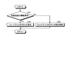
ここで、図11を参照し、制御装置150によって手扱ぎモードを有効状態と無効状態とに切り換えるモード切換制御に関する一例の制御フローについて説明する。図11は、モード切換制御に関する一例のフローチャートである。なお、図11では、コンバイン1の走行を停止させた状態で行われるモード切換制御について説明する。
Here, with reference to FIG. 11, an example of a control flow regarding mode switching control in which the control device 150 switches the handling mode between the valid state and the invalid state will be described. FIG. 11 is a flowchart of an example related to mode switching control. In addition, FIG. 11 demonstrates the mode switching control performed in the state which stopped the combine 1 driving | running | working.
制御装置150は、先ず、エンジン自動調整スイッチ161の入力結果に基づいて、エンジン自動調整スイッチ161がON操作されているか否かを判定する(ステップS1)。制御装置150は、エンジン自動調整スイッチ161がON操作されていると判定すると(ステップS1:Yes)、脱穀装置5の駆動要求があるか否かを判定する(ステップS2)。一方で、制御装置150は、エンジン自動調整スイッチ161がON操作されていないと判定すると(ステップS1:No)、後述するステップS6に進む。
First, the control device 150 determines whether or not the engine automatic adjustment switch 161 is turned on based on the input result of the engine automatic adjustment switch 161 (step S1). If it determines with the engine automatic adjustment switch 161 being ON-operated (step S1: Yes), the control apparatus 150 will determine whether there exists a drive request | requirement of the threshing apparatus 5 (step S2). On the other hand, if the controller 150 determines that the engine automatic adjustment switch 161 is not turned on (step S1: No), the control device 150 proceeds to step S6 described later.
ここで、ステップS2における脱穀装置5の駆動要求の判定は、脱穀クラッチ検出センサ162または脱穀用ポテンショメーター163の検出結果に基づいて判定を行っている。つまり、制御装置150は、脱穀クラッチ検出センサ162により、脱穀クラッチ81の接続を検出すると、脱穀装置5の駆動要求があると判定する一方で、脱穀クラッチ81の接続の解除を検出すると、脱穀装置5の駆動要求がないと判定する。または、制御装置150は、脱穀用ポテンショメーター163によって検出された操作位置が刈取位置または脱穀位置である場合、脱穀装置5の駆動要求があると判定する一方で、操作位置が刈取位置または脱穀位置以外の操作位置である場合、脱穀装置5の駆動要求がないと判定する。
Here, the determination of the drive request of the threshing device 5 in step S2 is performed based on the detection result of the threshing clutch detection sensor 162 or the threshing potentiometer 163. That is, when the control device 150 detects the connection of the threshing clutch 81 when the threshing clutch detection sensor 162 detects the connection of the threshing clutch 81, the control device 150 detects the release of the connection of the threshing clutch 81. 5 determines that there is no drive request. Alternatively, when the operation position detected by the threshing potentiometer 163 is the cutting position or the threshing position, the control device 150 determines that there is a drive request for the threshing apparatus 5, while the operation position is other than the cutting position or the threshing position. It is determined that there is no drive request for the threshing device 5.
制御装置150は、脱穀装置5の駆動要求があると判定すると(ステップS2:Yes)、コンバイン1が走行停止しているか否かを判定する(ステップS3)。一方で、制御装置150は、脱穀装置5の駆動要求がないと判定すると(ステップS2:No)、後述するステップS6に進む。
When determining that there is a drive request for the threshing device 5 (step S2: Yes), the control device 150 determines whether or not the combine 1 has stopped running (step S3). On the other hand, if it determines with the control apparatus 150 not having the drive request | requirement of the threshing apparatus 5 (step S2: No), it will progress to step S6 mentioned later.
ここで、ステップS3におけるコンバイン1の走行停止の判定は、走行用ポテンショメーター164、車速センサ165または駐車ブレーキセンサ166の検出結果に基づいて判定を行っている。つまり、制御装置150は、走行用ポテンショメーター164によって検出された走行操作レバー6Hの操作位置が中立位置である場合、コンバイン1が走行停止していると判定する一方で、中立位置以外の操作位置である場合、コンバイン1が走行停止していないと判定する。または、制御装置150は、車速センサ165によって検出された走行速度がゼロである場合、コンバイン1が走行停止していると判定する一方で、走行速度がゼロより大きい場合、コンバイン1が走行停止していないと判定する。または、制御装置150は、駐車ブレーキセンサ166によりブレーキ操作が行われていることを検出すると、コンバイン1が走行停止していると判定する一方で、ブレーキ操作が行われていないことを検出すると、コンバイン1が走行停止していないと判定する。
Here, the determination of the travel stop of the combine 1 in step S3 is made based on the detection results of the travel potentiometer 164, the vehicle speed sensor 165, or the parking brake sensor 166. That is, when the operation position of the travel operation lever 6H detected by the travel potentiometer 164 is the neutral position, the control device 150 determines that the combine 1 is stopped traveling, but at an operation position other than the neutral position. If there is, it is determined that the combine 1 has not stopped running. Alternatively, the control device 150 determines that the combine 1 is stopped when the traveling speed detected by the vehicle speed sensor 165 is zero, while the combine 1 stops traveling when the traveling speed is greater than zero. Judge that it is not. Alternatively, when the control device 150 detects that the brake operation is being performed by the parking brake sensor 166, the control device 150 determines that the combine 1 has stopped running, while detecting that the brake operation is not being performed. It is determined that the combine 1 has not stopped running.
制御装置150は、コンバイン1が走行停止していると判定すると(ステップS3:Yes)、手扱ぎスイッチ167がON操作されたか否かを判定する(ステップS4)。一方で、制御装置150は、コンバイン1が走行停止していないと判定すると(ステップS3:No)、後述するステップS6に進む。
When determining that the combine 1 has stopped running (step S3: Yes), the control device 150 determines whether or not the hand switch 167 has been turned ON (step S4). On the other hand, when determining that the combine 1 has not stopped running (No at Step S3), the control device 150 proceeds to Step S6 described later.
制御装置150は、手扱ぎスイッチ167の検出結果から、手扱ぎスイッチ167がON操作されたと判定すると(ステップS4:Yes)、手扱ぎモードを有効状態とする(ステップS5)。一方で、制御装置150は、手扱ぎスイッチ167の検出結果から、手扱ぎスイッチ167がON操作されていないと判定すると(ステップS4:No)、手扱ぎモードを無効状態とする(ステップS6)。
If it is determined from the detection result of the handle switch 167 that the handle switch 167 has been turned ON (step S4: Yes), the control device 150 sets the handle mode to a valid state (step S5). On the other hand, if the control device 150 determines from the detection result of the handle switch 167 that the handle switch 167 is not turned on (step S4: No), the controller 150 sets the handle mode to an invalid state (step S4). S6).
そして、制御装置150は、ステップS5またはステップS6を実行すると、再びステップS1に進んで、上記したモード切換制御に関する制御フローを繰り返し実行する。
Then, when executing step S5 or step S6, control device 150 proceeds to step S1 again and repeatedly executes the control flow relating to the mode switching control described above.
制御装置150は、手扱ぎモードを有効状態とすると、エンジン20の回転数を予め設定された設定回転数(設定回転速度)まで低くするエンジン低回転制御を実行する。ここで、設定回転数は、エンジン20の定格回転数よりも低く、エンジン20のアイドリング時における回転数(アイドリング回転数)よりも高くなる回転数である。そして、制御装置150は、エンジン低回転制御を実行することで、フィードチェン13による穀稈の搬送速度を遅くすることができる。なお、制御装置150は、エンジン低回転制御の実行時において、穀粒排出オーガ9を駆動可能なエンジン回転数とすることが好ましい。
The control device 150 executes engine low speed control that lowers the rotational speed of the engine 20 to a preset rotational speed (set rotational speed) when the handling mode is set to the valid state. Here, the set rotational speed is a rotational speed that is lower than the rated rotational speed of the engine 20 and higher than the rotational speed when the engine 20 is idling (idling rotational speed). And the control apparatus 150 can slow down the conveyance speed of the grain straw by the feed chain 13 by performing engine low-rotation control. In addition, it is preferable that the control device 150 sets the engine speed at which the grain discharge auger 9 can be driven when the engine low speed control is executed.
また、制御装置150は、手扱ぎモードを有効状態とすると、フィードチェン13の搬送速度が遅くなるようにフィードチェン低速側変速制御を実行する。つまり、制御装置150は、フィードチェン低速側変速制御を実行し、変速用モータ111を制御して、ギヤボックス100のシフタ軸108により移動体103dを低速側変速位置へ移動させることで、フィードチェン13の搬送速度を低速とする。なお、制御装置150は、フィードチェン低速側変速制御を実行する手扱ぎモードの有効条件として、少なくとも脱穀クラッチ81の接続と、駐車ブレーキのブレーキ操作とが満たされた場合に実行することが好ましい。また、制御装置150は、フィードチェン低速側変速制御を実行する手扱ぎモードの有効条件として、少なくとも脱穀クラッチ81の接続と、副変速の中立状態とが満たされた場合に実行してもよい。ここで、副変速について簡単に説明する。エンジン20には、上記の油圧式無段変速機(HST)が接続されると共に、油圧式無段変速機に走行ミッションが接続され、走行ミッションから走行装置3へ動力が伝達されることで、コンバイン1が走行する。走行ミッション内には、有段変速装置である副変速装置が設けられ、副変速装置は、低速、中立(標準またはニュートラルともいう)、高速の変速段を有している。低速は低速走行を行うときの変速段であり、中立は動力の伝達を遮断するときの変速段であり、高速は路上走行(高速走行)を行うときの変速段である。上記の副変速の中立状態とは、副変速装置の変速段が中立の変速段となっていることである。また、制御装置150は、フィードチェン低速側変速制御を実行する手扱ぎモードの有効条件として、少なくとも脱穀クラッチ81の接続と、走行操作レバー6Hの中立位置とが満たされた場合に実行してもよい。
Further, the control device 150 executes the feed chain low speed side shift control so that the transport speed of the feed chain 13 is slowed down when the handling mode is in the valid state. That is, the control device 150 executes the feed chain low-speed shift control, controls the shift motor 111, and moves the moving body 103d to the low-speed shift position by the shifter shaft 108 of the gear box 100. 13 is a low speed. Note that the control device 150 is preferably executed when at least the connection of the threshing clutch 81 and the brake operation of the parking brake are satisfied as the effective condition of the handling mode for executing the feed chain low speed side shift control. . Further, the control device 150 may be executed when at least the connection of the threshing clutch 81 and the neutral state of the sub-shift are satisfied as the effective conditions of the hand-handling mode for executing the feed chain low speed side shift control. . Here, the sub-shift will be briefly described. The engine 20 is connected to the hydraulic continuously variable transmission (HST), and a traveling mission is connected to the hydraulic continuously variable transmission, so that power is transmitted from the traveling mission to the traveling device 3. Combine 1 runs. A sub-transmission that is a stepped transmission is provided in the traveling mission, and the sub-transmission has low, neutral (also referred to as standard or neutral), and high speed gears. The low speed is a shift stage when performing low-speed travel, the neutral is a shift stage when interrupting transmission of power, and the high speed is a shift stage when performing road travel (high speed travel). The neutral state of the sub-transmission means that the shift stage of the sub-transmission device is a neutral shift stage. In addition, the control device 150 is executed when at least the connection of the threshing clutch 81 and the neutral position of the traveling operation lever 6H are satisfied as the effective conditions of the handling mode for executing the feed chain low speed side shift control. Also good.
また、制御装置150は、手扱ぎモードを有効状態とすると、搬送穀稈層厚センサ175により検出される穀稈の層厚と手扱ぎモードの経過時間とから、排出される排藁の推定総量を算出し、推定総量が予め設定された設定総量を上回った場合、モニタ6Dに、「コンバインを移動してください」という旨の警告表示を行ったり、警報ブザー195によりその旨の報知を行ったりしてもよい。ここで、警報ブザー195は、制御装置150に接続されており、コンバイン1に関する各種警報を発することが可能となっている。また、制御装置150は、排出される排藁の推定総量が予め設定された設定総量を上回った場合、モニタ6Dに、「カッタを確認してください」という旨の警告表示を行ったり、警報ブザー195によりその旨の報知を行ったりしてもよい。
In addition, when the handling mode is set to the valid state, the control device 150 determines the amount of waste discharged from the grain thickness detected by the transporting grain thickness sensor 175 and the elapsed time of the handling mode. When the estimated total amount is calculated and the estimated total amount exceeds the preset total amount, a warning message indicating “Please move the combine” is displayed on the monitor 6D, or the alarm buzzer 195 notifies that fact. You may go. Here, the alarm buzzer 195 is connected to the control device 150 and can issue various alarms related to the combine 1. Further, when the estimated total amount of discharged waste exceeds the preset total amount, the control device 150 displays a warning message “Please check the cutter” on the monitor 6D, or displays an alarm buzzer. A notification to that effect may be given by 195.
また、制御装置150には、手扱ぎモードであることを運転者に報知するための手扱ぎモードランプ190が接続されており、手扱ぎモードを有効状態にすると、手扱ぎモードランプ190を点灯させる。この手扱ぎモードランプ190は、キャビン6の運転席6S周りに設けられ、具体的に、操作装置6Cの操作パネルに配置されている。なお、制御装置150は、手扱ぎモードランプ190に代えて、モニタ6Dに「手扱ぎモードON」等の表示を行ってもよい。
In addition, the control device 150 is connected with a hand-handling mode lamp 190 for notifying the driver that it is in the hand-handling mode. Turn on 190. The handling mode lamp 190 is provided around the driver's seat 6S of the cabin 6 and is specifically disposed on the operation panel of the operating device 6C. Note that the control device 150 may display “handling mode ON” or the like on the monitor 6D instead of the handing mode lamp 190.
また、制御装置150は、エンジン低回転制御の実行時、唐箕5Fの回転数の低下を抑制すべく、唐箕回転数補正制御を実行する。唐箕回転数補正制御は、唐箕変速機構69の駆動源となる唐箕モータ191を制御することで、唐箕5Fの回転数を補正する。つまり、この唐箕モータ191は制御装置150に接続され、制御装置150は、唐箕モータ191を制御することにより唐箕変速機構69の変速制御を実行する。制御装置150は、手扱ぎモードが有効にされ、エンジン低回転制御が実行されると、唐箕モータ191により唐箕変速機構69を変速制御することで、唐箕5Fの回転数がエンジン低回転制御の実行前の回転数となるように、高速側に変速する。なお、唐箕回転数補正制御では、唐箕5Fの回転数が、エンジン低回転制御の実行前の回転数となるように高速側に変速したが、高速側に変速する構成であれば、特に限定されない。すなわち、唐箕回転数補正制御では、唐箕5Fの回転数が、エンジン低回転制御の実行前の回転数以下で、唐箕回転数補正制御を実行しないときの唐箕5Fの回転数よりも大きくなれば、いずれの回転数であってもよい。
In addition, the control device 150 executes the red pepper speed correction control in order to suppress a decrease in the rotational speed of the red pepper 5F when the engine low speed control is executed. The rotary speed correction control corrects the rotational speed of the hot car 5F by controlling the hot motor 191 that is a drive source of the hot gear transmission mechanism 69. In other words, the red pepper motor 191 is connected to the control device 150, and the control device 150 executes the shift control of the redshift gear mechanism 69 by controlling the red pepper motor 191. When the handling mode is enabled and the engine low speed control is executed, the control device 150 controls the speed change mechanism 69 by the speed change motor 191 so that the rotation speed of the speed change 5F is controlled by the engine low speed control. The speed is changed to the high speed side so that the rotation speed before execution is obtained. Note that, in the red pepper speed correction control, the rotational speed of the red pepper 5F is shifted to the high speed side so as to be the rotational speed before the execution of the engine low speed control, but there is no particular limitation as long as the speed is shifted to the high speed side. . That is, in the rotation speed correction control, if the rotation speed of the red pepper 5F is equal to or less than the rotation speed before execution of the engine low speed control and is larger than the rotation speed of the red pepper 5F when the rotation speed correction control is not executed, Any rotation number may be sufficient.
また、制御装置150には、選別棚5Cのシーブ面(上面)に付着する付着物を清掃する図示しないシーブスクレーパの駆動源となるシーブモータ192が接続されている。制御装置150は、手扱ぎモードを有効状態とすると、シーブモータ192を制御することで、シーブスクレーパの作動を停止させる。
The control device 150 is connected to a sheave motor 192 serving as a drive source for a sheave scraper (not shown) that cleans deposits adhering to the sheave surface (upper surface) of the sorting shelf 5C. When the handling mode is enabled, the control device 150 controls the sheave motor 192 to stop the operation of the sheave scraper.
また、制御装置150には、エンジン20の動力を刈取装置7へ伝達する動力伝達経路に設けられた図示しない刈取クラッチの駆動源となる刈取クラッチモータ193が接続されている。制御装置150は、刈取クラッチモータ193により刈取クラッチを係合させることで、エンジン20の動力を刈取装置7へ伝達する一方で、刈取クラッチの係合を解除することで、エンジン20の動力の刈取装置7への伝達を遮断する。制御装置150は、手扱ぎモードを有効にすると、刈取クラッチモータ193を制御することで、刈取クラッチの係合を解除し、エンジン20の動力の刈取装置7への伝達を遮断する。ここで、刈取装置7は、図示しない刈取昇降機構により昇降されており、制御装置150は、刈取昇降機構により刈取装置7を下降した場合、刈取クラッチモータ193により刈取クラッチを係合させるが、手扱ぎモードが有効となっている場合、刈取昇降機構により刈取装置7を下降した場合であっても、刈取クラッチの係合を解除した状態を維持する。
Further, the control device 150 is connected to a cutting clutch motor 193 serving as a driving source for a cutting clutch (not shown) provided in a power transmission path for transmitting the power of the engine 20 to the cutting device 7. The control device 150 transmits the power of the engine 20 to the cutting device 7 by engaging the cutting clutch with the cutting clutch motor 193, while cutting the power of the engine 20 by releasing the engagement of the cutting clutch. The transmission to the device 7 is cut off. When the handling mode is enabled, the control device 150 controls the reaping clutch motor 193 to release the engagement of the reaping clutch and interrupt the transmission of the power of the engine 20 to the reaping device 7. Here, the reaping device 7 is lifted and lowered by a reaping / lowering mechanism (not shown). When the reaping device 7 is lowered by the reaping / lowering mechanism, the control device 150 engages the reaping clutch by the reaping clutch motor 193. When the handling mode is enabled, the state where the engagement of the cutting clutch is released is maintained even when the cutting device 7 is lowered by the cutting lifting mechanism.
なお、ステップS3におけるコンバイン1の走行停止の判定は、駐車ブレーキセンサ166の検出結果に基づいて行うことが好ましい。この場合、制御装置150は、コンバイン1が走行停止となった状態を確実に判定することが可能となる。このとき、制御装置150は、ステップS3において駐車ブレーキによるブレーキ操作がされていないと判定した状態で、手扱ぎスイッチ167がON操作された場合は、モニタ6Dに、「駐車ブレーキをかけてから手扱ぎスイッチを操作してください」等の警告表示を行ってもよい。また、制御装置150は、ステップS3において駐車ブレーキを操作してコンバイン1を走行停止させた場合、手扱ぎモードの有効状態において、駐車ブレーキが解除されると、手扱ぎモードを有効状態から無効状態となるようにモード切換制御を実行してもよい。
In addition, it is preferable to determine the travel stop of the combine 1 in step S3 based on the detection result of the parking brake sensor 166. In this case, the control device 150 can reliably determine the state in which the combine 1 has stopped traveling. At this time, the control device 150 determines that the brake operation by the parking brake has not been performed in step S3, and if the hand switch 167 is turned on, the monitor 6D displays “After applying the parking brake”. A warning message such as “Please operate the hand switch” may be displayed. In addition, when the control device 150 operates the parking brake and stops the combine 1 in step S3, when the parking brake is released in the enabled state of the handling mode, the control mode 150 is changed from the enabled state. Mode switching control may be executed so as to be in an invalid state.
次に、図12を参照し、制御装置150によって手扱ぎモードを有効状態と無効状態とに切り換えるモード切換制御に関する一例の制御フローについて説明する。図12は、モード切換制御に関する一例のフローチャートである。なお、図12では、コンバイン1を低速走行させた状態で行われるモード切換制御について説明する。
Next, an example control flow relating to mode switching control in which the control device 150 switches the handling mode between the valid state and the invalid state will be described with reference to FIG. FIG. 12 is a flowchart of an example relating to mode switching control. In addition, FIG. 12 demonstrates the mode switching control performed in the state which made the combine 1 drive low speed.
制御装置150は、先ず、エンジン自動調整スイッチ161の入力結果に基づいて、エンジン自動調整スイッチ161がON操作されているか否かを判定する(ステップS11)。制御装置150は、エンジン自動調整スイッチ161がON操作されていると判定すると(ステップS11:Yes)、脱穀装置5の駆動要求があるか否かを判定する(ステップS12)。一方で、制御装置150は、エンジン自動調整スイッチ161がON操作されていないと判定すると(ステップS11:No)、後述するステップS17に進む。
First, the control device 150 determines whether or not the engine automatic adjustment switch 161 is turned on based on the input result of the engine automatic adjustment switch 161 (step S11). If it determines with the engine automatic adjustment switch 161 being ON-operated (step S11: Yes), the control apparatus 150 will determine whether there exists a drive request | requirement of the threshing apparatus 5 (step S12). On the other hand, if the controller 150 determines that the engine automatic adjustment switch 161 is not turned on (step S11: No), the control device 150 proceeds to step S17 described later.
制御装置150は、脱穀装置5の駆動要求があると判定すると(ステップS12:Yes)、コンバイン1が低速走行しているか否かを判定する(ステップS13)。一方で、制御装置150は、脱穀装置5の駆動要求がないと判定すると(ステップS12:No)、後述するステップS17に進む。
If it determines with the control apparatus 150 having the drive request | requirement of the threshing apparatus 5 (step S12: Yes), it will determine whether the combine 1 is drive | working low speed (step S13). On the other hand, if it determines with the control apparatus 150 having no drive request | requirement of the threshing apparatus 5 (step S12: No), it will progress to step S17 mentioned later.
ここで、ステップS13におけるコンバイン1の低速走行の判定は、走行用ポテンショメーター164または車速センサ165の検出結果に基づいて行っている。つまり、制御装置150は、走行用ポテンショメーター164によって検出された走行操作レバー6Hの操作位置が低速位置である場合、コンバイン1が低速走行していると判定する一方で、低速位置以外の操作位置である場合、コンバイン1が低速走行していないと判定する。または、制御装置150は、車速センサ165によって検出された走行速度が、低速走行とされる所定の速度の範囲内である場合、コンバイン1が低速走行していると判定する一方で、低速走行とされる所定の速度の範囲外である場合、コンバイン1が低速走行していないと判定する。
Here, the determination of the low speed travel of the combine 1 in step S13 is performed based on the detection result of the travel potentiometer 164 or the vehicle speed sensor 165. That is, when the operation position of the travel operation lever 6H detected by the travel potentiometer 164 is a low speed position, the control device 150 determines that the combine 1 is traveling at a low speed, but at an operation position other than the low speed position. If there is, it is determined that the combine 1 is not traveling at a low speed. Alternatively, the control device 150 determines that the combine 1 is traveling at a low speed when the traveling speed detected by the vehicle speed sensor 165 is within a predetermined speed range that is a low-speed traveling, When it is out of the predetermined speed range, it is determined that the combine 1 is not traveling at a low speed.
制御装置150は、コンバイン1が低速走行していると判定すると(ステップS13:Yes)、刈取装置7によって刈り取られる穀稈が有るか否かを判定する(ステップS14)。一方で、制御装置150は、コンバイン1が低速走行していないと判定すると(ステップS13:No)、後述するステップS17に進む。
When determining that the combine 1 is traveling at a low speed (step S13: Yes), the control device 150 determines whether or not there is a culm to be cut by the reaping device 7 (step S14). On the other hand, when determining that the combine 1 is not traveling at a low speed (step S13: No), the control device 150 proceeds to step S17 described later.
ここで、ステップS14における刈り取られる穀稈の有無の判定は、搬送穀稈検出センサ169または刈取り穀稈検出センサ170の検出結果に基づいて行っている。つまり、制御装置150は、搬送穀稈検出センサ169により搬送される穀稈が検出されると、刈取装置7によって刈り取られる穀稈が有ると判定する一方で、搬送される穀稈が検出されないと、刈取装置7によって刈り取られる穀稈がないと判定する。または、制御装置150は、刈取り穀稈検出センサ170により刈取対象穀稈が検出されると、刈取装置7によって刈り取られる穀稈が有ると判定する一方で、刈取対象穀稈が検出されないと、刈取装置7によって刈り取られる刈取対象穀稈がないと判定する。よって、制御装置150は、搬送穀稈検出センサ169により搬送中の穀稈が検出されている状態では、手扱ぎモードの有効状態への切り換わりを牽制する構成となっている。また、制御装置150は、刈取り穀稈検出センサ170により刈取対象穀稈が検出されている状態では、手扱ぎモードの有効状態への切り換わりを牽制する構成となっている。
Here, the determination of the presence or absence of the harvested culm in step S14 is performed based on the detection result of the transported culm detection sensor 169 or the harvested culm detection sensor 170. That is, when the control device 150 detects the culm that is transported by the transporting culm detection sensor 169, it determines that there is a culm that is harvested by the reaping device 7, while the transported culm is not detected. Then, it is determined that there is no cereal that is cut by the cutting device 7. Alternatively, the control device 150 determines that there is a culm to be harvested by the reaping device 7 when the reaping target culm is detected by the reaping culm detection sensor 170, but if the reaping target culm is not detected, It is determined that there is no harvesting culm to be trimmed by the device 7. Therefore, the control device 150 is configured to check the switching to the effective state of the handling mode in a state in which the transporting kernel detecting sensor 169 detects the operating kernel. In addition, the control device 150 is configured to check the switching to the effective state of the handling mode in a state where the harvesting kernel is detected by the harvesting kernel detection sensor 170.
制御装置150は、刈取装置7によって刈り取られる穀稈が有ると判定すると(ステップS14:Yes)、手扱ぎスイッチ167がON操作されたか否かを判定する(ステップS15)。一方で、制御装置150は、刈取装置7によって刈り取られる穀稈がないと判定すると(ステップS14:No)、後述するステップS17に進む。
When it is determined that there is a cereal husk cut by the reaping device 7 (step S14: Yes), the control device 150 determines whether or not the handling switch 167 is turned on (step S15). On the other hand, if the control apparatus 150 determines that there is no grain cocoon cut by the reaping apparatus 7 (step S14: No), it will progress to step S17 mentioned later.
制御装置150は、手扱ぎスイッチ167の検出結果から、手扱ぎスイッチ167がON操作されたと判定すると(ステップS15:Yes)、手扱ぎモードを有効状態とする(ステップS16)。一方で、制御装置150は、手扱ぎスイッチ167の検出結果から、手扱ぎスイッチ167がON操作されていないと判定すると(ステップS15:No)、手扱ぎモードを無効状態とする(ステップS17)。
If it is determined from the detection result of the handle switch 167 that the handle switch 167 has been turned ON (step S15: Yes), the control device 150 sets the handle mode to an effective state (step S16). On the other hand, when the control device 150 determines from the detection result of the handle switch 167 that the handle switch 167 has not been turned ON (step S15: No), the controller 150 sets the handle mode to an invalid state (step S15). S17).
そして、制御装置150は、ステップS16またはステップS17を実行すると、再びステップS11に戻って、上記したモード切換制御に関する制御フローを繰り返し実行する。
When step S16 or step S17 is executed, control device 150 returns to step S11 again and repeatedly executes the control flow related to the mode switching control described above.
以上から、制御装置150は、ステップS14において、搬送穀稈検出センサ169または刈取り穀稈検出センサ170により穀稈が検出されると、モード切換制御により手扱ぎモードを無効状態とする。
From the above, when the cereal is detected by the transported culm detection sensor 169 or the cutting culm detection sensor 170 in step S14, the control device 150 disables the handling mode by the mode switching control.
なお、上記したモード切換制御は、一例であり、例えば、下記するステップをさらに追加してもよい。制御装置150は、手扱ぎスイッチ167がON操作されたか否かを判定する(ステップS4またはステップS15の実行)前に、規制部材14が開放位置L1にあるか否かを判定してもよい。つまり、制御装置150は、規制部材位置検出センサ172の検出結果から、規制部材14が開放位置L1にあると判定すると、手扱ぎモードの有効条件を満たすと判定する一方で、規制部材14が規制位置L2にあると判定すると、手扱ぎモードの有効条件を満たさないと判定する。このため、作業者が規制部材14を開放位置L1に移動させることで、手扱ぎモードの有効条件を満たすことができ、手扱ぎモードを自動的に有効状態に切換える構成とすることができる。
The mode switching control described above is an example, and for example, the following steps may be further added. The control device 150 may determine whether or not the regulating member 14 is in the open position L1 before determining whether or not the hand switch 167 is turned on (execution of step S4 or step S15). . That is, when the control device 150 determines from the detection result of the restriction member position detection sensor 172 that the restriction member 14 is in the open position L1, the control device 150 determines that the effective condition of the handling mode is satisfied. If it determines with it being in the control position L2, it determines with not satisfy | filling the effective conditions of hand-handling mode. For this reason, when the operator moves the restricting member 14 to the open position L1, it is possible to satisfy the effective condition of the handling mode and to automatically switch the handling mode to the enabled state. .
また、制御装置150は、ステップS14における判定と合わせて、刈取装置7が駆動しているか否かを判定してもよい。つまり、制御装置150は、刈取駆動状態検出センサ171により刈取装置7の駆動を検出しないと、手扱ぎモードの有効条件を満たすと判定する一方で、刈取駆動状態検出センサ171により刈取装置7の駆動を検出すると、手扱ぎモードの有効条件を満たさないと判定する。つまり、制御装置150は、搬送穀稈検出センサ169または刈取り穀稈検出センサ170により穀稈が検出され、且つ刈取駆動状態検出センサ171により刈取装置7の駆動が検出されると、モード切換制御により手扱ぎモードを無効状態とし、手扱ぎモードの有効状態への切り換わりを牽制する。また、制御装置150は、搬送穀稈検出センサ169により穀稈が検出された状態で、手扱ぎスイッチ167がON操作された場合は、モニタ6Dに、「刈取部の藁を処理してから手扱ぎスイッチを操作してください」等の警告表示を行ってもよい。
Further, the control device 150 may determine whether or not the reaping device 7 is driven in conjunction with the determination in step S14. In other words, the control device 150 determines that the effective condition of the handling mode is satisfied unless the cutting drive state detection sensor 171 detects the driving of the cutting device 7, while the cutting drive state detection sensor 171 determines that the cutting device 7 When the drive is detected, it is determined that the effective condition of the hand handling mode is not satisfied. In other words, the control device 150 performs the mode switching control when the husk is detected by the transporting husk detection sensor 169 or the cutting husk detection sensor 170 and the driving of the cutting device 7 is detected by the cutting drive state detection sensor 171. The hand handling mode is disabled and the switching of the hand handling mode to the enabled state is checked. In addition, when the handling switch 167 is turned ON in a state where the corn straw is detected by the transporting cocoon detection sensor 169, the control device 150 displays “after processing the cocoon of the cutting part” on the monitor 6 </ b> D. A warning message such as “Please operate the hand switch” may be displayed.
また、制御装置150は、手扱ぎスイッチ167がON操作されたか否かを判定する(ステップS4またはステップS15の実行)前に、上記した副変速装置の変速段が中立の変速段または低速の変速段であるか否かを判定してもよい。つまり、制御装置150は、副変速装置の変速段が中立の変速段または低速の変速段であると判定すると、手扱ぎモードの有効条件を満たすと判定する一方で、副変速装置の変速段が中立の変速段または低速の変速段でないと判定すると、手扱ぎモードの有効条件を満たさないと判定する。また、制御装置150は、副変速装置の変速段が高速の変速段であると判定された状態で、手扱ぎスイッチ167がON操作された場合は、モニタ6Dに、「副変速を中立に戻してから手扱ぎスイッチを操作してください」等の警告表示を行ってもよい。
Further, before determining whether or not the hand switch 167 is turned on (execution of step S4 or step S15), the control device 150 sets the shift speed of the auxiliary transmission described above to a neutral shift speed or a low speed. You may determine whether it is a gear stage. That is, if the control device 150 determines that the gear position of the sub-transmission device is a neutral gear position or a low-speed gear position, the control device 150 determines that the effective condition of the handling mode is satisfied, while the gear position of the sub-transmission device If it is determined that is not a neutral shift speed or a low speed shift speed, it is determined that the effective condition for the handling mode is not satisfied. Further, when the handwheel switch 167 is turned on in a state in which the shift stage of the sub-transmission device is determined to be a high-speed shift stage, the control device 150 displays “the sub-shift is set to neutral”. Please operate the handle switch after returning. "
また、制御装置150は、手扱ぎスイッチ167がON操作されたか否かを判定する(ステップS4またはステップS15の実行)前に、選別棚5C上を移動する夾雑物および穀粒の量が、所定の流量以下であるか否かを判定してもよい。つまり、制御装置150は、流量センサ173の検出結果から、夾雑物および穀粒が所定の流量以下であると判定すると、手扱ぎモードの有効条件を満たすと判定する一方で、夾雑物および穀粒が所定の流量よりも大きいと判定すると、手扱ぎモードの有効条件を満たさないと判定する。また、制御装置150は、夾雑物および穀粒が所定の流量よりも大きいと判定された状態で、手扱ぎスイッチ167がON操作された場合は、モニタ6Dに、「脱穀部をしばらく回してから手扱ぎスイッチを操作してください」等の警告表示を行ってもよい。
Further, the control device 150 determines whether or not the handling switch 167 has been turned ON (execution of step S4 or step S15), and the amount of impurities and grains moving on the sorting shelf 5C is You may determine whether it is below a predetermined flow rate. That is, if the controller 150 determines from the detection result of the flow sensor 173 that the foreign matter and the grain are below a predetermined flow rate, the control device 150 determines that the effective condition of the handling mode is satisfied, while the foreign matter and the grain If it is determined that the grain is larger than the predetermined flow rate, it is determined that the effective condition of the hand-handling mode is not satisfied. In addition, when the handling switch 167 is turned on in a state where it is determined that the impurities and the grains are larger than the predetermined flow rate, the control device 150 displays “turn the threshing portion for a while” on the monitor 6D. "Please operate the hand switch from the beginning."
また、制御装置150は、手扱ぎスイッチ167がON操作されたか否かを判定する(ステップS4またはステップS15の実行)前に、排藁搬送装置により搬送される排藁が一定の層厚以下であるか否かを判定してもよい。つまり、制御装置150は、排藁層厚センサ174の検出結果から、排藁が一定の層厚以下であると判定すると、手扱ぎモードの有効条件を満たすと判定する一方で、排藁が一定の層厚よりも大きいと判定すると、手扱ぎモードの有効条件を満たさないと判定する。また、制御装置150は、排藁が一定の層厚よりも大きいと判定された状態で、手扱ぎスイッチ167がON操作された場合は、モニタ6Dに、上記と同様に、「脱穀部をしばらく回してから手扱ぎスイッチを操作してください」等の警告表示を行ってもよい。
Further, the control device 150 determines whether or not the hand switch 167 has been turned ON (execution of step S4 or step S15), and the waste transported by the waste transport device is below a certain layer thickness. It may be determined whether or not. That is, if the controller 150 determines from the detection result of the exclusion layer thickness sensor 174 that the exclusion is equal to or less than a certain layer thickness, the control device 150 determines that the effective condition of the handling mode is satisfied. If it is determined that the thickness is larger than the certain layer thickness, it is determined that the effective condition of the hand-handling mode is not satisfied. In addition, when the handle switch 167 is turned on in a state in which the waste is determined to be larger than a certain layer thickness, the control device 150 displays “ Turn the button for a while and then operate the handle switch ".
また、制御装置150は、手扱ぎスイッチ167がON操作されたか否かを判定する(ステップS4またはステップS15の実行)前に、穀稈搬送装置10に搬送される穀稈が一定の層厚以下であるか否かを判定してもよい。つまり、制御装置150は、搬送穀稈層厚センサ175の検出結果から、穀稈が一定の層厚以下であると判定すると、手扱ぎモードの有効条件を満たすと判定する一方で、穀稈が一定の層厚よりも大きいと判定すると、手扱ぎモードの有効条件を満たさないと判定する。また、制御装置150は、搬送される穀稈が一定の層厚よりも大きいと判定された状態で、手扱ぎスイッチ167がON操作された場合は、モニタ6Dに、上記と同様に、「脱穀部をしばらく回してから手扱ぎスイッチを操作してください」等の警告表示を行ってもよい。
In addition, the control device 150 determines whether or not the hand switch 167 has been turned ON (execution of step S4 or step S15), and the cereals conveyed to the cereal conveyance device 10 have a certain thickness. You may determine whether it is below. That is, when the controller 150 determines from the detection result of the transported culm layer thickness sensor 175 that the culm is equal to or less than a certain layer thickness, the control device 150 determines that the effective condition of the handling mode is satisfied. Is determined to be larger than a certain layer thickness, it is determined that the effective condition of the hand-handling mode is not satisfied. In addition, when the handle switch 167 is turned on in a state where it is determined that the cereal to be transported is larger than a certain layer thickness, the control device 150 causes the monitor 6D to display “ Please turn the threshing portion for a while and then operate the handle switch ".
また、制御装置150は、脱穀装置5の駆動要求がないと判定された状態で、手扱ぎスイッチ167がON操作された場合は、モニタ6Dに、「脱穀クラッチを入れてから手扱ぎスイッチを操作してください」等の警告表示を行ってもよい。
In addition, when it is determined that there is no drive request for the threshing device 5 and the hand switch 167 is turned ON, the control device 150 displays a “hand switch after inserting the threshing clutch” on the monitor 6D. May be displayed. "
次に、手扱ぎモードの有効状態における制御装置150の各種制御について説明する。制御装置150は、手扱ぎモードの有効状態において、緊急停止スイッチ168が操作されると、エンジン20を停止させるエンジン緊急停止制御を実行する。以下、図13を参照し、手扱ぎモードが有効状態である場合において、緊急停止スイッチ168が操作されたときの制御装置150の制御フローについて説明する。図13は、緊急停止スイッチの操作時における制御装置の一例のフローチャートである。
Next, various controls of the control device 150 in the effective state of the handling mode will be described. When the emergency stop switch 168 is operated in the enabled state of the handling mode, the control device 150 executes engine emergency stop control for stopping the engine 20. Hereinafter, the control flow of the control device 150 when the emergency stop switch 168 is operated in the case where the handling mode is in the valid state will be described with reference to FIG. FIG. 13 is a flowchart of an example of the control device when operating the emergency stop switch.
制御装置150は、先ず、緊急停止スイッチ168の入力結果に基づいて、緊急停止スイッチ168がON操作されているか否かを判定する(ステップS21)。制御装置150は、緊急停止スイッチ168がON操作されていると判定すると(ステップS21:Yes)、脱穀装置5の駆動要求があるか否かを判定する(ステップS22)。一方で、制御装置150は、緊急停止スイッチ168がON操作されていないと判定すると(ステップS21:No)、再びステップS21に進む。
First, the control device 150 determines whether or not the emergency stop switch 168 is ON based on the input result of the emergency stop switch 168 (step S21). When determining that the emergency stop switch 168 is turned on (step S21: Yes), the control device 150 determines whether or not there is a drive request for the threshing device 5 (step S22). On the other hand, if the control device 150 determines that the emergency stop switch 168 is not turned ON (step S21: No), the control device 150 proceeds to step S21 again.
制御装置150は、脱穀装置5の駆動要求があると判定すると(ステップS22:Yes)、エンジン20の緊急停止を実行する(ステップS23)。一方で、制御装置150は、脱穀装置5の駆動要求がないと判定すると(ステップS22:No)、再びステップS21に進む。
If it determines with the control apparatus 150 having the drive request | requirement of the threshing apparatus 5 (step S22: Yes), it will perform the emergency stop of the engine 20 (step S23). On the other hand, if the control apparatus 150 determines that there is no drive request | requirement of the threshing apparatus 5 (step S22: No), it will progress to step S21 again.
制御装置150は、ステップS23において、エンジン20を緊急停止させると、警報ブザー195から緊急停止した旨を知らせる警報音を発する。また、制御装置150は、ステップS23において、エンジン20を緊急停止させると、フィードチェンクラッチモータ126を制御して、クラッチアーム121の溝部125とシフタ軸108の突起部124とを係合させ、移動体103dを中立位置に移動させることで、フィードチェン13のクラッチ係合を解除する。
In step S23, when the engine 20 is urgently stopped, the control device 150 emits an alarm sound notifying that the emergency stop has occurred from the alarm buzzer 195. Further, when the engine 20 is stopped urgently in step S23, the control device 150 controls the feed chain clutch motor 126 to engage the groove portion 125 of the clutch arm 121 and the projection portion 124 of the shifter shaft 108 to move. The clutch engagement of the feed chain 13 is released by moving the body 103d to the neutral position.
このとき、制御装置150は、手扱ぎモードが有効状態であり、エンジン低回転制御を実行していることから、低回転のエンジン20を停止させることができるため、エンジン20の回転を直ぐに停止することが可能となる。また、制御装置150は、手扱ぎモードが有効状態であり、フィードチェン低速側変速制御を実行していることから、低速のフィードチェン13のクラッチ係合を解除することができるため、フィードチェン13を直ぐに停止することが可能となる。
At this time, since the handling mode is in the valid state and the engine low-speed control is being executed, the control device 150 can stop the low-speed engine 20 and thus immediately stop the rotation of the engine 20. It becomes possible to do. In addition, since the control mode 150 is in the enabled state and the feed chain low speed side shift control is executed, the clutch of the low speed feed chain 13 can be released. 13 can be stopped immediately.
ステップS23の実行後、制御装置150は、緊急停止の解除操作が行われたか否かを判定する(ステップS24)。ここで、緊急停止の解除操作としては、緊急停止スイッチ168による緊急停止の解除操作、脱穀操作レバーによる緊急停止の解除操作または主電源スイッチ196による緊急停止の解除操作等がある。緊急停止スイッチ168による緊急停止の解除操作は、緊急停止スイッチ168の切操作(OFF操作)である。制御装置150は、緊急停止スイッチ168のOFF操作を検出すると、緊急停止の解除操作が行われたと判定する一方で、緊急停止スイッチ168のON操作を検出すると、緊急停止の解除操作が行われていないと判定する。また、脱穀操作レバーによる緊急停止の解除操作は、脱穀操作レバーの操作位置を刈取位置および脱穀位置以外の操作位置にすることである。制御装置150は、脱穀用ポテンショメーター163の検出結果から脱穀操作レバーが刈取位置および脱穀位置以外の操作位置にあると検出すると、緊急停止の解除操作が行われたと判定する一方で、脱穀操作レバーが刈取位置または脱穀位置にあると検出すると、緊急停止の解除操作が行われていないと判定する。さらに、主電源スイッチ196による緊急停止の解除操作は、主電源スイッチ196が切操作(OFF操作)された後、入操作(ON操作)されることである。ここで、主電源スイッチ196は、コンバイン1の始動時に電力を供給するために操作されるスイッチであり、制御装置150に接続されている。制御装置150は、主電源スイッチ196のOFF操作を検出した後、ON操作を検出すると、緊急停止の解除操作が行われたと判定する一方で、主電源スイッチ196のON操作のみを検出する、または主電源スイッチ196のOFF操作のみを検出すると、緊急停止の解除操作が行われていないと判定する。
After execution of step S23, the control device 150 determines whether or not an emergency stop cancellation operation has been performed (step S24). Here, the emergency stop release operation includes an emergency stop release operation by the emergency stop switch 168, an emergency stop release operation by the threshing operation lever, or an emergency stop release operation by the main power switch 196. The emergency stop release operation by the emergency stop switch 168 is a turning-off operation (OFF operation) of the emergency stop switch 168. When the control device 150 detects that the emergency stop switch 168 is turned off, the control device 150 determines that the emergency stop release operation is performed. On the other hand, when the control device 150 detects the emergency stop switch 168 ON operation, the emergency stop release operation is performed. Judge that there is no. Further, the emergency stop canceling operation by the threshing operation lever is to set the operation position of the threshing operation lever to an operation position other than the cutting position and the threshing position. When the control device 150 detects from the detection result of the threshing potentiometer 163 that the threshing operation lever is in an operation position other than the cutting position and the threshing position, the controller 150 determines that the emergency stop release operation has been performed, while the threshing operation lever If it detects that it exists in a cutting position or a threshing position, it will determine with the cancellation | release operation of emergency stop not being performed. Further, the emergency stop release operation by the main power switch 196 is an on operation (ON operation) after the main power switch 196 is turned off (OFF operation). Here, the main power switch 196 is a switch operated to supply power when the combine 1 is started, and is connected to the control device 150. When detecting an ON operation after detecting an OFF operation of main power switch 196, control device 150 determines that an emergency stop canceling operation has been performed, while detecting only an ON operation of main power switch 196, or If only the main power switch 196 OFF operation is detected, it is determined that the emergency stop canceling operation has not been performed.
制御装置150は、緊急停止の解除操作が行われたと判定すると(ステップS24:Yes)、緊急停止を解除する(ステップS25)。一方で、制御装置150は、緊急停止の解除操作が行われていないと判定すると(ステップS24:No)、再びステップS24に進む。
When determining that the emergency stop canceling operation has been performed (step S24: Yes), the control device 150 cancels the emergency stop (step S25). On the other hand, when determining that the emergency stop canceling operation has not been performed (step S24: No), the control device 150 proceeds to step S24 again.
ここで、ステップS25における緊急停止の解除としては、ステップS23において警報ブザー195から発した警報音を停止すること、およびステップS23において停止させたエンジン20の始動を可能とすることである。なお、ステップS25において、エンジン20は、脱穀装置5の駆動要求がないときのみ始動可能となることが好ましい。
Here, the release of the emergency stop in step S25 is to stop the alarm sound emitted from the alarm buzzer 195 in step S23 and to start the engine 20 stopped in step S23. In step S25, it is preferable that the engine 20 can be started only when there is no drive request for the threshing device 5.
制御装置150は、ステップS25の実行後、再びステップS21に進んで、上記した緊急停止スイッチ168が操作されたときの制御装置150の制御フローを繰り返し実行する。なお、ステップS23において、フィードチェンクラッチモータ126によりクラッチ係合が解除されたフィードチェン13は、下記する制御装置150の制御フローによって適宜クラッチ係合される。
After executing step S25, the control device 150 proceeds to step S21 again, and repeatedly executes the control flow of the control device 150 when the emergency stop switch 168 described above is operated. In step S23, the feed chain 13 whose clutch engagement is released by the feed chain clutch motor 126 is appropriately clutch-engaged by a control flow of the control device 150 described below.
図14を参照し、制御装置150によりフィードチェン13をクラッチ係合する制御フローについて説明する。図14は、フィードチェンのクラッチ係合に関する制御装置の一例のフローチャートである。
With reference to FIG. 14, a control flow for clutch-engaging the feed chain 13 by the control device 150 will be described. FIG. 14 is a flowchart of an example of a control device related to clutch engagement of the feed chain.
制御装置150は、先ず、脱穀装置5の駆動要求があるか否かを判定する(ステップS31)。制御装置150は、脱穀装置5の駆動要求があると判定すると(ステップS31:Yes)、フィードチェンクラッチモータ126を制御して、クラッチアーム121の溝部125とシフタ軸108の突起部124との係合を解除することで、フィードチェン13をクラッチ係合する(ステップS32)。一方で、制御装置150は、脱穀装置5の駆動要求がないと判定すると(ステップS31:No)、フィードチェンクラッチモータ126を制御して、クラッチアーム121の溝部125とシフタ軸108の突起部124とを係合させることで、フィードチェン13のクラッチ係合を解除する(ステップS33)。
First, the control device 150 determines whether or not there is a drive request for the threshing device 5 (step S31). When the control device 150 determines that there is a drive request for the threshing device 5 (step S31: Yes), the control device 150 controls the feed chain clutch motor 126 to engage the groove portion 125 of the clutch arm 121 and the projection portion 124 of the shifter shaft 108. By releasing the engagement, the feed chain 13 is engaged with the clutch (step S32). On the other hand, if the control device 150 determines that there is no request for driving the threshing device 5 (step S31: No), the control device 150 controls the feed chain clutch motor 126, and the groove portion 125 of the clutch arm 121 and the protruding portion 124 of the shifter shaft 108. And the clutch engagement of the feed chain 13 is released (step S33).
次に、手扱ぎモードの有効状態における制御装置150の他の制御について説明する。制御装置150は、手扱ぎモードが有効状態である場合、走行装置3を制御して、コンバイン1の車高を、作業者に対して手扱ぎ作業の作業位置が好適な位置となるように調整する車高調整制御を実行する。例えば、制御装置150は、車高調整制御を実行すると、コンバイン1が水平面と平行となるように、コンバイン1の車高を下げる。または、制御装置150は、車高調整制御を実行すると、左右方向において穀稈搬送装置10が配置されている側(左側)に下り傾斜するように、コンバイン1の車高を下げる。または、制御装置150は、車高調整制御を実行すると、前後方向において穀稈搬送装置10が配置されている側(前側)に下り傾斜するように、コンバイン1の車高を下げる。または、制御装置150は、車高調整制御を実行すると、前後左右方向において穀稈搬送装置10が配置されている側(左前側)に下り傾斜するように、コンバイン1の車高を下げる。これにより、制御装置150は、手扱ぎ作業を行う作業者に対し、手扱ぎ作業の作業位置を好適な位置とすることができ、作業の容易性を向上できることから、安全性を向上させることができる。なお、車高調整制御は、入切操作により任意に設定可能であり、車高調整制御を実行する入操作(ON操作)が行われた場合のみ実行する構成としてもよい。
Next, another control of the control device 150 in the enabled state of the handling mode will be described. When the hand-handling mode is in an effective state, the control device 150 controls the traveling device 3 so that the vehicle height of the combine 1 becomes a suitable position for the operator. The vehicle height adjustment control to be adjusted to is executed. For example, when executing the vehicle height adjustment control, the control device 150 lowers the vehicle height of the combine 1 so that the combine 1 is parallel to the horizontal plane. Alternatively, when the vehicle height adjustment control is executed, the control device 150 lowers the vehicle height of the combine 1 so as to incline downward toward the side (left side) where the grain feeder 10 is disposed in the left-right direction. Alternatively, when the vehicle height adjustment control is executed, the control device 150 lowers the vehicle height of the combine 1 so as to incline downward toward the side (front side) on which the grain feeder 10 is disposed in the front-rear direction. Alternatively, when the vehicle height adjustment control is executed, the control device 150 lowers the vehicle height of the combine 1 so as to be inclined downward in the front / rear / left / right direction to the side (left front side) on which the cereal conveyor device 10 is disposed. Thereby, the control device 150 can make the work position of the handling operation suitable for the worker who performs the handling operation, and can improve the ease of the operation, thereby improving the safety. be able to. The vehicle height adjustment control can be arbitrarily set by an on / off operation, and may be executed only when an on operation (ON operation) for executing the vehicle height adjustment control is performed.
また、制御装置150は、手扱ぎモードが有効状態である場合、車高調整制御を実行したが、穀粒排出オーガ9を駆動させる場合には、車高調整制御を禁止する。穀粒排出オーガ9の駆動としては、例えば、搬送筒9bを伸長させたり、搬送筒9bの排出口から穀粒を排出したりすることである。これにより、制御装置150は、穀粒排出オーガ9からグレンタンク8に溜められた穀粒を排出する場合、車高調整制御を禁止するため、穀粒排出オーガ9の搬送筒9bを適切に支持することができ、また、安定した穀粒の排出を実行することができる。
Further, the control device 150 executes the vehicle height adjustment control when the handling mode is in an effective state, but prohibits the vehicle height adjustment control when driving the grain discharge auger 9. Driving the grain discharge auger 9 includes, for example, extending the transport cylinder 9b or discharging the grain from the discharge port of the transport cylinder 9b. Thereby, when discharging the grain stored in the grain tank 8 from the grain discharge auger 9, the control device 150 appropriately supports the transport cylinder 9b of the grain discharge auger 9 in order to prohibit the vehicle height adjustment control. And stable grain discharge can be carried out.
また、制御装置150は、手扱ぎモードが有効状態である場合、車高調整制御を実行したが、コンバイン1の走行速度が所定の速度以上となった場合には、車高調整制御を禁止する。これにより、制御装置150は、コンバイン1の走行を安定的なものとすることができる。
In addition, the control device 150 executes the vehicle height adjustment control when the handling mode is in an effective state, but prohibits the vehicle height adjustment control when the traveling speed of the combine 1 exceeds a predetermined speed. To do. Thereby, the control apparatus 150 can make driving | running | working of the combine 1 stable.
また、制御装置150は、手扱ぎモードが有効状態である場合、車高調整制御を実行した。ここで、車高調整制御は、予め設定された車高となるように車高を自動で調整する車高自動調整制御と、手動で調整した車高となるように車高を自動で調整する車高手動調整制御とがある。制御装置150は、手扱ぎモードが有効状態である場合、車高調整制御として、車高手動調整制御を、車高自動調整制御に比して優先させて実行する。これにより、制御装置150は、作業者が任意に設定した車高となるように、コンバイン1の車高を調整することができる。
Moreover, the control apparatus 150 performed vehicle height adjustment control, when the handling mode is an effective state. Here, in the vehicle height adjustment control, the vehicle height is automatically adjusted so that the vehicle height is set in advance, and the vehicle height is automatically adjusted so that the vehicle height is adjusted manually. There is a vehicle height manual adjustment control. When the handling mode is in an effective state, the control device 150 executes the vehicle height manual adjustment control as vehicle height adjustment control with priority over the vehicle height automatic adjustment control. Thereby, the control apparatus 150 can adjust the vehicle height of the combine 1 so that it may become the vehicle height arbitrarily set by the operator.
また、制御装置150は、手扱ぎモードが有効状態である場合、穀粒排出オーガ9による穀粒の排出を停止する穀粒排出停止制御を実行してもよい。つまり、制御装置150は、穀粒排出停止制御を実行することで、穀粒の排出によって加わるエンジン20の負荷を低減することができる。なお、穀粒排出停止制御では、穀粒の排出のみを停止すればよく、搬送筒9bの伸縮および移動の実行については許容する。これにより、穀粒排出オーガ9の搬送筒9bの位置にかかわらず、手扱ぎモードで手扱ぎ作業を行うことが可能となる。
Moreover, the control apparatus 150 may perform the grain discharge | emission stop control which stops discharge | emission of the grain by the grain discharge auger 9 when the handling mode is an effective state. That is, the control apparatus 150 can reduce the load of the engine 20 applied by the grain discharge by executing the grain discharge stop control. In the grain discharge stop control, only the grain discharge needs to be stopped, and the extension and movement of the transport cylinder 9b and the execution of the movement are allowed. Thereby, regardless of the position of the conveying cylinder 9b of the grain discharge auger 9, it becomes possible to perform the handling operation in the handling mode.
一方、制御装置150は、穀粒排出オーガ9による穀粒の排出を行っている場合、手扱ぎスイッチ167がON操作された場合は、手扱ぎモードの有効条件を満たさないとして、手扱ぎモードを無効状態としてもよい。このとき、制御装置150は、モニタ6Dに、「オーガの排出を停止してから手扱ぎスイッチを操作してください」という旨の警告表示を行ってもよく、または、警報ブザー195によりその旨を報知してもよい。
On the other hand, when discharging the grain by the grain discharging auger 9, the control device 150 assumes that the effective condition of the handling mode is not satisfied when the handling switch 167 is turned on. It is good also as a disabled state. At this time, the control device 150 may display a warning message on the monitor 6D to the effect that “please stop the auger discharge and then operate the hand switch”, or the alarm buzzer 195 May be notified.
また、制御装置150は、手扱ぎモードが有効状態である場合、エンジン低回転制御を実行したが、穀粒排出オーガ9による穀粒の排出を行っている場合、エンジン20の回転数を定格回転数に維持する制御を実行してもよい。このとき、制御装置150は、モニタ6Dに、「オーガ排出中につきエンジン回転数を維持します」等の警告表示を行ってもよい。
Further, the control device 150 executes the engine low rotation control when the handling mode is in an effective state, but when the kernel discharge is performed by the kernel discharge auger 9, the rotation speed of the engine 20 is rated. You may perform control maintained at rotation speed. At this time, the control device 150 may display a warning message such as “Maintain engine speed during auger discharge” on the monitor 6D.
以上のように、本実施形態の構成によれば、制御装置150は、フィードチェン変速制御を実行することにより、通常の刈取作業中において、車速または走行操作レバー6Hの操作位置に応じて、ギヤボックス100によりフィードチェン13の搬送速度を変速することができる。このため、制御装置150は、穀稈搬送装置10によって脱穀装置5へ搬送される穀稈の層厚を適正化することができ、脱穀装置5による脱穀効率を高めることができる。また、制御装置150は、手扱ぎモードの有効状態となると、フィードチェン低速側変速制御を実行するため、フィードチェン13の搬送速度を低速とすることができる。さらに、制御装置150は、手扱ぎモードの有効状態となると、エンジン低回転制御を実行するため、フィードチェン13の搬送速度を更に低速とすることができることから、穀稈をフィードチェン13へ円滑に供給して脱穀処理することができる。そして、制御装置150は、手扱ぎモードの有効状態において、緊急停止スイッチ168がON操作されると、エンジン緊急停止制御が実行されることで、エンジン20が停止するため、フィードチェン13の搬送速度が低速となっていることにより、フィードチェン13をより素早く停止させることができる。
As described above, according to the configuration of the present embodiment, the control device 150 performs the feed chain shift control, so that the gear 150 or the operation position of the traveling operation lever 6H can be controlled during the normal cutting operation. The conveyance speed of the feed chain 13 can be changed by the box 100. For this reason, the control apparatus 150 can optimize the layer thickness of the cereals conveyed to the threshing apparatus 5 by the cereal conveyance apparatus 10, and can improve the threshing efficiency by the threshing apparatus 5. Moreover, since the control apparatus 150 will perform feed chain low speed side shift control, if it becomes the enabled state of hand-handling mode, it can make the conveyance speed of the feed chain 13 low. Furthermore, since the control device 150 executes the engine low speed control when the hand-handling mode is enabled, the feed speed of the feed chain 13 can be further reduced. And can be threshed. Then, when the emergency stop switch 168 is turned on in the enabled state of the handling mode, the control device 150 executes the engine emergency stop control, so that the engine 20 is stopped. Since the speed is low, the feed chain 13 can be stopped more quickly.
また、本実施形態の構成によれば、制御装置150は、手扱ぎモードの有効状態となると、エンジン低回転制御を実行する。このとき、エンジン20の回転数を定格回転数よりも低く、アイドリング時における回転数(アイドリング回転数)よりも高くすることができる。このため、制御装置150は、緊急停止スイッチ168のON操作時におけるフィードチェン13の素早い停止を実現しつつ、脱穀装置5による脱穀処理を実行するのに十分な動力を確保することができる。
Further, according to the configuration of the present embodiment, the control device 150 executes the engine low speed control when the handing mode is enabled. At this time, the rotational speed of the engine 20 can be lower than the rated rotational speed and higher than the rotational speed during idling (idling rotational speed). For this reason, the control device 150 can secure sufficient power to execute the threshing process by the threshing device 5 while realizing a quick stop of the feed chain 13 when the emergency stop switch 168 is turned on.
また、本実施形態の構成によれば、制御装置150は、走行操作レバー6Hが中立位置または低速位置に操作された場合、あるいはコンバイン1が走行停止または低速走行する場合、アイドリング回転制御を実行する。このため、制御装置150は、エンジン20の回転数をアイドリング回転数まで低下できることから、エンジン20の燃料消費量および排気ガスの排出量を低減することができる。一方で、制御装置150は、脱穀クラッチ81が接続状態である場合、アイドリング回転制御が実行されないため、エンジン20の回転数が低下することなく、フィードチェン13の搬送速度を維持することができるため、刈取装置7により刈り取った穀稈を脱穀装置5へ素早く搬送して脱穀処理することができる。そして、制御装置150は、手扱ぎモードを有効状態とすると、エンジン低回転制御を実行するため、フィードチェン13の搬送速度を低速にできることから、穀稈をフィードチェン13へ円滑に供給して脱穀処理することができる。
Further, according to the configuration of the present embodiment, the control device 150 executes idling rotation control when the traveling operation lever 6H is operated to the neutral position or the low speed position, or when the combine 1 stops traveling or travels at low speed. . For this reason, the control device 150 can reduce the rotational speed of the engine 20 to the idling rotational speed, and thus can reduce the fuel consumption amount and the exhaust gas exhaust amount of the engine 20. On the other hand, since the idling rotation control is not executed when the threshing clutch 81 is in the connected state, the control device 150 can maintain the conveyance speed of the feed chain 13 without reducing the rotation speed of the engine 20. The cereals harvested by the reaping device 7 can be quickly conveyed to the threshing device 5 for threshing treatment. And since the control apparatus 150 makes the handling mode effective state, in order to perform engine low-rotation control, since the conveyance speed of the feed chain 13 can be made low, the grain flour is supplied to the feed chain 13 smoothly. Threshing can be performed.
また、本実施形態の構成によれば、制御装置150は、規制部材14を開放位置L1に移動させることにより、手扱ぎモードの有効条件を満たし、フィードチェン低速側変速制御を実行するため、フィードチェン13の搬送速度を低速にできることから、穀稈をフィードチェン13へ円滑に供給して脱穀処理することができる。
Further, according to the configuration of the present embodiment, the control device 150 moves the regulating member 14 to the open position L1, thereby satisfying the effective condition of the handling mode and executing the feed chain low speed side shift control. Since the conveying speed of the feed chain 13 can be reduced, the cereal can be smoothly supplied to the feed chain 13 for threshing.
また、本実施形態の構成によれば、制御装置150は、刈取駆動状態検出センサ171により刈取装置7が駆動していると判定した場合、また、搬送穀稈検出センサ169により搬送される穀稈を検出した場合、手扱ぎモードを有効状態とすることがない。このため、通常の刈取作業中に、誤操作等によって手扱ぎスイッチ167がON操作された場合であっても、制御装置150は、手扱ぎモードを有効状態としないため、エンジン低回転制御およびフィードチェン低速側変速制御を実行することを抑制でき、刈取作業の能率低下を抑制することができる。
Moreover, according to the configuration of the present embodiment, when the control device 150 determines that the reaping drive state detection sensor 171 determines that the reaping device 7 is driven, the control device 150 also transports the culm that is transported by the transporting culm detection sensor 169. Is detected, the handling mode is not activated. For this reason, even if the hand switch 167 is turned ON by an erroneous operation or the like during a normal cutting operation, the control device 150 does not set the hand mode to an effective state. Execution of the feed chain low speed side shift control can be suppressed, and a reduction in efficiency of the cutting operation can be suppressed.
また、本実施形態の構成によれば、制御装置150は、刈取り穀稈検出センサ170により刈取前の穀稈を検出した場合、手扱ぎモードを有効状態とすることがない。このため、例えばコンバイン1を圃場に進入させながら刈取装置7により刈取作業を開始する場合にであっても、刈取り穀稈検出センサ170により穀稈を検出していれば、エンジン低回転制御およびフィードチェン低速側変速制御を実行することを抑制できるため、刈取作業の能率低下を抑制することができる。
Further, according to the configuration of the present embodiment, the control device 150 does not set the handling mode to the valid state when the culm before chopping is detected by the chopped culm detection sensor 170. For this reason, for example, even when the harvesting device 7 starts the harvesting operation while the combine 1 is entering the field, if the harvesting kernel detection sensor 170 detects the kernel, the engine low-rotation control and feed Since it is possible to suppress execution of the chain low speed side shift control, it is possible to suppress a reduction in efficiency of the cutting operation.
なお、本実施形態において、フィードチェン13は、有段のギヤボックス100により高速側または低速側に変速されたが、HST等の無段変速機を適用してもよい。
In this embodiment, the feed chain 13 is shifted to the high speed side or the low speed side by the stepped gear box 100, but a continuously variable transmission such as HST may be applied.