JP5777256B2 - Game machine - Google Patents

Game machine Download PDF

Info

Publication number
JP5777256B2
JP5777256B2 JP2013075851A JP2013075851A JP5777256B2 JP 5777256 B2 JP5777256 B2 JP 5777256B2 JP 2013075851 A JP2013075851 A JP 2013075851A JP 2013075851 A JP2013075851 A JP 2013075851A JP 5777256 B2 JP5777256 B2 JP 5777256B2
Authority
JP
Japan
Prior art keywords
display
effect
image
touch panel
game
Prior art date
Legal status (The legal status is an assumption and is not a legal conclusion. Google has not performed a legal analysis and makes no representation as to the accuracy of the status listed.)
Active
Application number
JP2013075851A
Other languages
Japanese (ja)
Other versions
JP2013128812A5 (en
JP2013128812A (en
Inventor
青木 一
一 青木
Current Assignee (The listed assignees may be inaccurate. Google has not performed a legal analysis and makes no representation or warranty as to the accuracy of the list.)
Universal Entertainment Corp
Original Assignee
Universal Entertainment Corp
Priority date (The priority date is an assumption and is not a legal conclusion. Google has not performed a legal analysis and makes no representation as to the accuracy of the date listed.)
Filing date
Publication date
Application filed by Universal Entertainment Corp filed Critical Universal Entertainment Corp
Priority to JP2013075851A priority Critical patent/JP5777256B2/en
Publication of JP2013128812A publication Critical patent/JP2013128812A/en
Publication of JP2013128812A5 publication Critical patent/JP2013128812A5/ja
Application granted granted Critical
Publication of JP5777256B2 publication Critical patent/JP5777256B2/en
Active legal-status Critical Current
Anticipated expiration legal-status Critical

Links

Images

Description

本発明は、遊技機に関し、特に画像を表示可能な表示手段を備えたパチンコ遊技機やパチスロ遊技機などの遊技機に関する。   The present invention relates to a gaming machine, and more particularly to a gaming machine such as a pachinko gaming machine or a pachislot gaming machine provided with display means capable of displaying an image.

従来より、遊技盤における遊技領域に向けて遊技球を発射させる遊技に加えて、所定の操作を行うことによって演出表示の態様を変更する遊技を行うことが可能なパチンコ遊技機が提供されている。   Conventionally, a pachinko gaming machine capable of performing a game in which a mode of effect display is changed by performing a predetermined operation in addition to a game in which a game ball is launched toward a game area on a game board has been provided. .

例えば、特許文献1には、表示手段の前方にタッチパネルが設けられ、遊技者による当該タッチパネルの操作に応じて、遊技者の必要とする情報や、遊技状態に応じた情報を示す情報画像等を表示するパチンコ遊技機が記載されている。   For example, in Patent Document 1, a touch panel is provided in front of the display means, and information required by the player, information images indicating information corresponding to the game state, and the like are displayed according to the operation of the touch panel by the player. The pachinko machine to be displayed is described.

このように、タッチパネルの入力操作に応じて情報画像等を表示可能な特許文献1の遊技機によれば、遊技者が必要とするような情報を、遊技者の所望のタイミングで提示することが可能となる。   As described above, according to the gaming machine of Patent Document 1 that can display an information image or the like in accordance with an input operation on the touch panel, information required by the player can be presented at a timing desired by the player. It becomes possible.

特開2006−288477号公報JP 2006-288477 A

しかしながら、特許文献1の遊技機では、タッチパネル等の入力操作による演出表示の態様の変更は、主に遊技状況を確認するときに利用されるのみで、タッチパネルを操作すること自体には特段の面白みはなかった。   However, in the gaming machine of Patent Document 1, the change of the display mode of the effect display by the input operation of the touch panel or the like is mainly used when checking the game situation, and the operation of the touch panel itself is particularly interesting. There was no.

そのため、折角遊技者の入力操作が可能なタッチパネルを設けたとしても、当該タッチパネルの操作頻度が低下してしまう虞がある。   Therefore, even if a touch panel that can be input by a corner player is provided, the operation frequency of the touch panel may be reduced.

そこで、本発明は、タッチパネルの操作に面白みを持たせることにより、当該タッチパネルの操作頻度を高めることが可能な遊技機を提供することを目的とする。   Therefore, an object of the present invention is to provide a gaming machine capable of increasing the operation frequency of the touch panel by making the operation of the touch panel interesting.

請求項に記載の本発明は、遊技球が転動する遊技領域を有する遊技盤と、演出画像の表示が可能な演出表示手段と、前記演出表示手段と対向する位置に設けられ、遊技者による接触を検出可能であり、当該接触を検出した際に接触位置を特定するタッチパネルと、前記演出表示手段に演出画像を表示させる制御を行う演出表示制御手段と、所定条件が成立したことに基づいて、遊技者に利益を与える当たり抽選を行う当たり抽選手段と、前記当たり抽選手段による抽選結果に基づいて、リーチ状態を発生させる制御を行うリーチ状態発生手段とを備え、前記演出表示制御手段は、前記タッチパネルへの遊技者の接触且つ所定位置への移動である接触移動が行われたときに表示内容を変化させ、表示内容の変化後である表示結果態様により前記当たり抽選手段の抽選結果の示唆、又は前記リーチ状態発生手段の制御により生じるリーチ状態の予告を行う特定の予告演出を実行する制御が実行可能であり、前記特定の予告演出を実行する制御は、前記接触移動が行われたときにのみ実行され、かつ、前記リーチ状態の発生前のタイミングで演出画像の表示変化を行う、ことを特徴とする The present invention described in claim 1 is provided at a position opposite to the effect display means, a game board having a game area in which a game ball rolls, an effect display means capable of displaying an effect image, and a player Based on the fact that a predetermined condition has been established, a touch panel that identifies a contact position when the contact is detected, an effect display control unit that performs control to display an effect image on the effect display unit Te, a per lottery means for performing hit lottery to benefit to the player, based on a lottery result by prior Kito or drawing means, and a reach state generating means for controlling to generate a reach state, the effect display control The means changes the display content when the player's contact with the touch panel and the contact movement, which is a movement to a predetermined position, is performed, and the display result mode after the change of the display content A control for executing a specific notice effect for performing a notice of the lottery result of the winning lottery means or performing a notice of the reach state generated by the control of the reach state generating means can be executed, and the control for executing the specific notice effect is It is executed only when the contact movement is performed, and the effect image display is changed at a timing before the reach state occurs .

本発明によれば以下の効果を奏することができる。   According to the present invention, the following effects can be obtained.

すなわち、本発明によれば、タッチパネルの操作に面白みを持たせることができ、当該タッチパネルの操作頻度を高めることが可能な遊技機を提供することが可能となる。   That is, according to the present invention, it is possible to provide a gaming machine that can make the operation of the touch panel interesting and can increase the operation frequency of the touch panel.

本実施の形態に係る遊技機を示す斜視図である。It is a perspective view which shows the game machine which concerns on this Embodiment. 本実施形態のパチンコ遊技機における概観を示す分解斜視図である。It is a disassembled perspective view which shows the general view in the pachinko gaming machine of this embodiment. 図1に示した遊技機の遊技盤を示す正面図である。It is a front view which shows the game board of the gaming machine shown in FIG. 図1に示した遊技機の制御系を示すブロック図である。It is a block diagram which shows the control system of the gaming machine shown in FIG. 本実施の形態に係る遊技機の主制御回路の処理手順を示すフローチャートである。It is a flowchart which shows the process sequence of the main control circuit of the game machine which concerns on this Embodiment. 本実施の形態に係る特別図柄制御処理の処理手順を示すフローチャートである。It is a flowchart which shows the process sequence of the special symbol control process which concerns on this Embodiment. 本実施の形態に係る特別図柄記憶チェック処理の処理手順を示すフローチャートである。It is a flowchart which shows the process sequence of the special symbol memory | storage check process which concerns on this Embodiment. 本実施の形態に係るコマンド受信割込処理の処理手順を示すフローチャートである。It is a flowchart which shows the process sequence of the command reception interruption process which concerns on this Embodiment. 本実施の形態に係る遊技機の副制御回路によるメイン処理の処理手順を示すフローチャートである。It is a flowchart which shows the process sequence of the main process by the sub control circuit of the game machine which concerns on this Embodiment. 本実施の形態に係るコマンド解析処理の処理手順を示すフローチャートである。It is a flowchart which shows the process sequence of the command analysis process which concerns on this Embodiment. 本実施の形態に係るシステムタイマ割込処理の処理手順を示すフローチャートである。It is a flowchart which shows the process sequence of the system timer interruption process which concerns on this Embodiment. 本実施の形態に係るタッチパネル接触検知処理の処理手順を示すフローチャートである。It is a flowchart which shows the process sequence of the touch-panel contact detection process which concerns on this Embodiment. 本実施の形態に係る大当たり抽選テーブルの一例を示す図である。It is a figure which shows an example of the jackpot lottery table which concerns on this Embodiment. 本実施の形態に係る演出表示パターン決定テーブルの一例を示す図である。It is a figure which shows an example of the production | presentation display pattern determination table which concerns on this Embodiment. 本実施の形態に係る変動表示パターン決定テーブルの一例を示す図である。It is a figure which shows an example of the fluctuation | variation display pattern determination table which concerns on this Embodiment. 本実施の形態に係る装飾図柄の変動表示の進行態様の一例を示す説明図である。It is explanatory drawing which shows an example of the advancing mode of the change display of the decoration symbol which concerns on this Embodiment. 本実施の形態に係る装飾図柄の変動表示の態様の一例を示す図である。It is a figure which shows an example of the aspect of the fluctuation | variation display of the decoration symbol which concerns on this Embodiment. 本実施の形態に係る装飾図柄の変動表示の態様の一例を示す図である。It is a figure which shows an example of the aspect of the fluctuation | variation display of the decoration symbol which concerns on this Embodiment. 本実施の形態に係る液晶表示装置をタッチパネルを介して視認した様子を示す説明図である。It is explanatory drawing which shows a mode that the liquid crystal display device which concerns on this Embodiment was visually recognized via the touch panel. 本実施の形態に係る液晶表示装置をタッチパネルを介して視認した様子を示す説明図である。It is explanatory drawing which shows a mode that the liquid crystal display device which concerns on this Embodiment was visually recognized via the touch panel. 本実施の形態に係る演出画像の表示態様の一例を示す図である。It is a figure which shows an example of the display mode of the production image which concerns on this Embodiment. 本実施の形態に係る演出画像の表示態様の一例を示す図である。It is a figure which shows an example of the display mode of the production image which concerns on this Embodiment. 本実施の形態に係るタッチパネル、遊技盤及び液晶表示装置の配置状態を側方から見た説明図である。It is explanatory drawing which looked at the arrangement | positioning state of the touchscreen which concerns on this Embodiment, the game board, and the liquid crystal display device from the side.

以下、本発明を実施するための形態を、図面を参照しつつさらに具体的に説明する。ここで、添付図面において同一の部材には同一の符号を付しており、また、重複した説明は省略されている。なお、ここでの説明は本発明が実施される最良の形態であることから、本発明は当該形態に限定されるものではない。   Hereinafter, embodiments for carrying out the present invention will be described more specifically with reference to the drawings. Here, in the accompanying drawings, the same reference numerals are given to the same members, and duplicate descriptions are omitted. In addition, since description here is the best form by which this invention is implemented, this invention is not limited to the said form.

以下、本実施の形態におけるパチンコ遊技機(遊技機)1の構成について、図面を参照しながら説明する。図1〜図23は、プリペイドカード方式を適用した遊技機1の一実施の形態を示している。   Hereinafter, the configuration of the pachinko gaming machine (game machine) 1 according to the present embodiment will be described with reference to the drawings. 1 to 23 show an embodiment of a gaming machine 1 to which a prepaid card system is applied.

図1は本実施の形態に係る遊技機を示す斜視図、図2は本実施形態のパチンコ遊技機における概観を示す分解斜視図、図3は図1に示した遊技機の遊技盤を示す正面図、図4は図1に示した遊技機の制御系を示すブロック図、図5は本実施の形態に係る遊技機の主制御回路の処理手順を示すフローチャート、図6は本実施の形態に係る特別図柄制御処理の処理手順を示すフローチャート、図7は本実施の形態に係る特別図柄記憶チェック処理の処理手順を示すフローチャート、図8は本実施の形態に係るコマンド受信割込処理の処理手順を示すフローチャート、図9は本実施の形態に係る遊技機の副制御回路によるメイン処理の処理手順を示すフローチャート、図10は本実施の形態に係るコマンド解析処理の処理手順を示すフローチャート、図11は本実施の形態に係るシステムタイマ割込処理の処理手順を示すフローチャート、図12は本実施の形態に係るタッチパネル接触検知処理の処理手順を示すフローチャート、図13は本実施の形態に係る大当たり抽選テーブルの一例を示す図、図14は本実施の形態に係る演出表示パターン決定テーブルの一例を示す図、図15は本実施の形態に係る変動表示パターン決定テーブルの一例を示す図、図16は本実施の形態に係る装飾図柄の変動表示の進行態様の一例を示す説明図、図17は本実施の形態に係る装飾図柄の変動表示の態様の一例を示す図、図18は本実施の形態に係る装飾図柄の変動表示の態様の一例を示す図、図19は本実施の形態に係る液晶表示装置をタッチパネルを介して視認した様子を示す説明図、図20は本実施の形態に係る液晶表示装置をタッチパネルを介して視認した様子を示す説明図、図21は本実施の形態に係る演出画像の表示態様の一例を示す図、図22は本実施の形態に係る演出画像の表示態様の一例を示す図、図23は本実施の形態に係るタッチパネル、遊技盤及び液晶表示装置の配置状態を側方から見た説明図である。   1 is a perspective view showing a gaming machine according to the present embodiment, FIG. 2 is an exploded perspective view showing an overview of the pachinko gaming machine according to the present embodiment, and FIG. 3 is a front view showing a gaming board of the gaming machine shown in FIG. 4 is a block diagram showing a control system of the gaming machine shown in FIG. 1, FIG. 5 is a flowchart showing a processing procedure of a main control circuit of the gaming machine according to the present embodiment, and FIG. 6 is shown in the present embodiment. 7 is a flowchart showing the processing procedure of the special symbol control processing, FIG. 7 is a flowchart showing the processing procedure of the special symbol storage check processing according to the present embodiment, and FIG. 8 is the processing procedure of the command reception interrupt processing according to the present embodiment. FIG. 9 is a flowchart showing a processing procedure of main processing by the sub-control circuit of the gaming machine according to the present embodiment, and FIG. 10 is a flowchart showing a processing procedure of command analysis processing according to the embodiment. FIG. 11 is a flowchart showing the processing procedure of the system timer interrupt processing according to the present embodiment, FIG. 12 is a flowchart showing the processing procedure of the touch panel contact detection processing according to the present embodiment, and FIG. 13 is related to the present embodiment. FIG. 14 is a diagram showing an example of a jackpot lottery table, FIG. 14 is a diagram showing an example of an effect display pattern determination table according to the present embodiment, and FIG. 15 is a diagram showing an example of a variable display pattern determination table according to the present embodiment. 16 is an explanatory diagram showing an example of the progress of the variation display of the decorative symbol according to the present embodiment, FIG. 17 is a diagram showing an example of the variation display of the decorative symbol according to the present embodiment, and FIG. FIG. 19 is a diagram illustrating an example of a variation display mode of decorative symbols according to the embodiment, FIG. 19 is an explanatory diagram illustrating a state in which the liquid crystal display device according to the present embodiment is visually recognized via a touch panel, and FIG. Explanatory drawing which shows a mode that the liquid crystal display device which concerns on embodiment was visually recognized via the touch panel, FIG. 21 is a figure which shows an example of the display mode of the effect image which concerns on this Embodiment, FIG. 22 concerns on this Embodiment FIG. 23 is a diagram illustrating an example of the display mode of the effect image, and FIG. 23 is an explanatory diagram of the arrangement state of the touch panel, the game board, and the liquid crystal display device according to the present embodiment as viewed from the side.

最初に、遊技機1の構成について、図1および図2を参照しながら説明する。   First, the configuration of the gaming machine 1 will be described with reference to FIGS. 1 and 2.

図1および図2に示すように、パチンコ遊技機1は、遊技盤2(図2)が装着されるとともに、前面に開口3aaが形成された本体枠3aと、その本体枠3aにおける開口3aaの内部に配設される各種の部品と、遊技盤2の前面側を視認可能に被うガラス板9bが嵌め込まれたガラス扉9aと、本体枠3aの後方に配置され、島設備に固定される外枠3bとから構成されている。   As shown in FIG. 1 and FIG. 2, the pachinko gaming machine 1 includes a main body frame 3a having a game board 2 (FIG. 2) mounted therein and an opening 3aa formed on the front surface, and an opening 3aa in the main body frame 3a. Various parts arranged inside, a glass door 9a fitted with a glass plate 9b covering the front side of the game board 2 so as to be visible, and a rear side of the main body frame 3a are fixed to island facilities. It is comprised from the outer frame 3b.

なお、本体枠3aは、その一方端が、ヒンジ(図示せず)を介して外枠3bに回動可能に取り付けられるようになっており、これら本体枠3aおよび外枠3bで遊技機本体3が構成されている。そして、このような遊技機本体3の本体枠3aに対して、本体枠3a上部の左右に固定されたスピーカ6a,6b(図4)を保護するスピーカカバー60a,60bを備える装飾ユニット60、液晶表示装置(演出表示手段)21、遊技盤2を視認可能に被うガラス扉9a、上皿部4、下皿部5および発射ハンドル7が取り付けられるようになっている。   The main body frame 3a is rotatably attached at one end to the outer frame 3b via a hinge (not shown). The main body frame 3a and the outer frame 3b allow the gaming machine main body 3 to be pivoted. Is configured. And with respect to the main body frame 3a of such a game machine main body 3, the decoration unit 60 provided with speaker covers 60a and 60b which protect the speakers 6a and 6b (FIG. 4) fixed to the left and right of the upper part of the main body frame 3a, liquid crystal A display device (effect display means) 21, a glass door 9 a that covers the game board 2 so as to be visible, an upper dish part 4, a lower dish part 5, and a launch handle 7 are attached.

ガラス扉9aおよび上皿部4は一体化して形成されており、この一体化された開閉扉(開閉体)は、その一端が本体枠3aに回動可能に軸支され、他端が本体枠3aに係合するようになっている。これにより、通常、ガラス扉9aは遊技盤2の前面(主面)に対面閉鎖した状態で遊技が行われる。   The glass door 9a and the upper plate part 4 are integrally formed, and one end of the integrated opening / closing door (opening / closing body) is pivotally supported by the main body frame 3a, and the other end of the main body frame. 3a is engaged. Thereby, a game is normally performed in a state in which the glass door 9a is face-to-face closed on the front surface (main surface) of the game board 2.

本体枠3aの開口3aaの内部には、後述するように、演出画像(例えば、遊技状態に対応したアニメーションやその他の報知情報など)等を表示可能な表示領域21aを有する液晶表示装置(演出表示手段)21、スペーサ11、遊技盤2等が配設されている。なお、遊技盤2、スペーサ11、液晶表示装置21以外の各種の部品(図示せず)については、理解を容易にするために説明を省略する。   Inside the opening 3aa of the main body frame 3a, as will be described later, a liquid crystal display device (effect display) having a display area 21a capable of displaying an effect image (for example, animation corresponding to a gaming state or other notification information). Means) 21, a spacer 11, a game board 2, etc. are provided. In addition, about various components (not shown) other than the game board 2, the spacer 11, and the liquid crystal display device 21, description is abbreviate | omitted in order to make an understanding easy.

遊技盤2は、その全部が光を透過する透過性を有する板形状の樹脂(透過性を有する部材)によって形成されている。この透過性を有する部材としては、例えば、アクリル樹脂、ポリカーボネート樹脂、メタクリル樹脂など各種の材質が該当する。また、遊技盤2は、ガラス扉9aにおけるガラス板9bと対向する主面側に、発射された遊技球が転勤流下が可能な遊技領域2aを有している。この遊技領域2aは、レール6に囲まれ、遊技球の転勤流下が可能な領域である。なお、上記遊技盤2は、透明であってもよいし、半透明であってもよい。また、合成樹脂以外の部材から構成されていてもよい。   The game board 2 is formed of a plate-like resin (a member having transparency) that has a light-transmitting property. Examples of the transparent member include various materials such as acrylic resin, polycarbonate resin, and methacrylic resin. Moreover, the game board 2 has the game area | region 2a in which the launched game ball can flow down on the main surface side facing the glass plate 9b in the glass door 9a. The game area 2a is an area surrounded by the rails 6 and capable of transferring a game ball. The game board 2 may be transparent or translucent. Moreover, you may be comprised from members other than a synthetic resin.

遊技領域2aは、レール6に包囲されており、図3に示すように、風車や障害釘等の障害物(図示せず)や、一般入賞装置12、通過ゲート13、始動口18、大入賞装置15、アウト口16、障害物28,29、などの遊技部材が配置されている。   The game area 2a is surrounded by the rail 6, and as shown in FIG. 3, obstacles such as windmills and obstacle nails (not shown), the general winning device 12, the passing gate 13, the starting port 18, the big prize Game members such as the device 15, the out port 16, and the obstacles 28 and 29 are arranged.

スペーサ11は、遊技盤2の後方(背面側)に配設されるとともに、液晶表示装置21の前方(前面側)に配設される。つまり、スペーサ11は、遊技盤2と液晶表示装置21によって扶持される。このスペーサ11は、透過性を有した材料で形成されており、中央に大きな貫通孔11aが設けられている。そして、スペーサ11は、貫通孔11aに、遊技に関する所定の情報を報知する電飾ユニット26等が納められるような厚みを提供する。   The spacer 11 is disposed behind (on the back side of) the game board 2 and on the front (front side) of the liquid crystal display device 21. That is, the spacer 11 is held between the game board 2 and the liquid crystal display device 21. The spacer 11 is made of a material having permeability, and a large through hole 11a is provided at the center. The spacer 11 provides a thickness that allows the through-hole 11a to receive an electrical decoration unit 26 that notifies predetermined information about the game.

また、スペーサ11の背面には、上述した液晶表示装置21が配置されている。つまり、液晶表示装置21は、図23に示すように、タッチパネル100の後方に位置する遊技盤2の背面側に配置されている(図23は、タッチパネル、遊技盤及び液晶表示装置の配置状態を側方から見た説明図である。同図においては、スペーサ11の記載を省略している)。なお、液晶表示装置21の表示領域21aは、演出画像を表示する領域と、表示領域21aのうち上側に位置する領域である上部領域800(図19、図20)と、表示領域21aのうち下側に位置する領域である下部領域850(図19、図20)と、装飾図柄(識別情報)の変動表示が行われる装飾図柄表示領域21b(図3、図17、図18)とからなっている。   The liquid crystal display device 21 described above is disposed on the back surface of the spacer 11. That is, the liquid crystal display device 21 is arranged on the back side of the game board 2 located behind the touch panel 100 as shown in FIG. 23 (FIG. 23 shows the arrangement state of the touch panel, the game board, and the liquid crystal display device. It is explanatory drawing seen from the side (In the same figure, description of the spacer 11 is abbreviate | omitted). The display area 21a of the liquid crystal display device 21 includes an area for displaying an effect image, an upper area 800 (FIGS. 19 and 20) that is an upper area of the display area 21a, and a lower area of the display area 21a. A lower region 850 (FIGS. 19 and 20) which is a region located on the side, and a decorative symbol display region 21b (FIGS. 3, 17, and 18) in which a decorative symbol (identification information) is displayed in a variable manner. Yes.

装飾図柄表示領域21bは、図17及び図18に示すように左リール部27a、中リール部27b、右リール部27cの3つに区分されており、それぞれのリール部で別々に装飾図柄の変動表示が行われるようになっている。   As shown in FIGS. 17 and 18, the decorative symbol display area 21b is divided into three parts, that is, a left reel portion 27a, a middle reel portion 27b, and a right reel portion 27c. Display is done.

また、遊技盤2およびスペーサ11が透過性を有した材料で形成された本実施の形態では、液晶表示装置21の表示領域21aが遊技盤2およびスペーサ11を通して視認可能に配置されている。ここで、液晶表示装置21にかえて、例えばCRT(陰極線管)あるいはプラズマディスプレイ等を用いることもできる。   In the present embodiment in which the game board 2 and the spacer 11 are formed of a permeable material, the display area 21 a of the liquid crystal display device 21 is disposed so as to be visible through the game board 2 and the spacer 11. Here, instead of the liquid crystal display device 21, for example, a CRT (cathode ray tube) or a plasma display can be used.

本実施形態のように、液晶表示装置21を、遊技盤2の背面側に設けることにより、例えば、障害釘の植設領域や役物、装飾部材等を設ける領域を大きくし、レイアウトの自由度も更に大きくすることが可能である。   By providing the liquid crystal display device 21 on the back side of the game board 2 as in the present embodiment, for example, the area for installing the obstacle nail, the area for providing the accessory, the decorative member, etc. is increased, and the degree of freedom in layout is increased. Can be further increased.

ここで、一般入賞装置12は、遊技球が入賞すると所定の数の遊技球が払い戻される装置、通過ゲート13は、遊技球が通過したことを契機として普通図柄表示器25a,25b(後述)を点滅させるための装置である。   Here, the general winning device 12 is a device in which a predetermined number of game balls are paid out when a game ball is won, and the passing gate 13 uses normal symbol indicators 25a and 25b (described later) when the game ball has passed. It is a device for blinking.

また、遊技盤2の略中央部上部には障害物28が設けられており、当該障害物28の下方には障害物29が設けられている。発射ハンドル7の操作によって遊技盤2に打ち出された遊技球において、障害物28,29に衝突した遊技球は、障害物28,29に沿って遊技領域2aの左側または右側の何れかに流下する。   In addition, an obstacle 28 is provided in the upper part of the center of the game board 2, and an obstacle 29 is provided below the obstacle 28. In the game ball launched into the game board 2 by the operation of the launch handle 7, the game ball colliding with the obstacles 28 and 29 flows down along the obstacles 28 and 29 to either the left side or the right side of the game area 2a. .

障害物29の下方には、遊技球の入賞が可能であるとともに、当該入賞した遊技球がその内部を通過可能な始動口(特定領域)18が設けられている。さらに始動口18は、当該始動口18の内部を遊技球が通過することが容易な開状態と、始動口18の内部を遊技球が通過することが困難な閉状態とに変化可能な可変翼18a,18bを有している。   Below the obstacle 29, there is provided a start port (specific area) 18 through which a game ball can be won and through which the winning game ball can pass. Further, the start port 18 is a variable wing that can be changed between an open state in which a game ball can easily pass through the start port 18 and a closed state in which it is difficult for a game ball to pass through the start port 18. 18a, 18b.

ここで、可変翼18a,18bの閉状態とは、可変翼18a,18bが閉じて遊技球が始動口18に入賞し難くなる状態のことである。一方、可変翼18a,18bにおける開状態とは、可変翼18a,18bが逆八字状に開口して遊技球が始動口18に入賞し易くなる状態のことである。また、通常時において始動口18は、閉状態となっている。   Here, the closed state of the variable wings 18 a and 18 b is a state in which the variable wings 18 a and 18 b are closed and it is difficult for the game ball to win the starting port 18. On the other hand, the open state in the variable wings 18a and 18b is a state in which the variable wings 18a and 18b open in an inverted eight-character shape and the game ball can easily win the starting port 18. Further, the start port 18 is closed during normal times.

この始動口18に遊技球が入賞してその内部を通過すると、特別図柄表示器24に表示される特別図柄や、液晶表示装置21における装飾図柄が変動及び停止するようになっている。なお、本実施の形態における始動口18には上述した可変翼18a,18bが設けられていたが、これに限られず、当該始動口18は、可変翼18a,18bが設けられない構造であってもよい。   When a game ball wins the start opening 18 and passes through the inside, the special symbol displayed on the special symbol display 24 and the decorative symbol on the liquid crystal display device 21 are changed and stopped. Although the above-described variable blades 18a and 18b are provided in the starting port 18 in the present embodiment, the present invention is not limited to this, and the starting port 18 has a structure in which the variable blades 18a and 18b are not provided. Also good.

始動口18の下方には、大入賞装置15が設けられている。大入賞装置15は、扉15aおよび遊技球の受け入れ口を有するいわゆるアタッカー式の開閉装置であって、扉15aが閉じて遊技球の入賞が困難となる閉状態と、扉15aが開放して遊技球の入賞が容易となる開状態との開閉動作が行われるようになっている。さらに、大入賞装置15の内部には、大入賞装置15に入賞した遊技球の通過が可能な通過領域が設けられている。   A big prize device 15 is provided below the start opening 18. The grand prize winning device 15 is a so-called attacker-type opening / closing device having a door 15a and a game ball receiving port. The door 15a is closed to make it difficult to win a game ball, and the door 15a is opened to play a game. An opening / closing operation with an open state that facilitates winning of a ball is performed. Furthermore, a passing area in which a game ball that has won the big winning device 15 can pass is provided inside the big winning device 15.

また、アウト口16は、一般入賞装置12、始動口18、大入賞装置15の何れにも入賞(入球)しなかった遊技球が流入して回収される装置である。なお、回収された遊技球は遊技領域2a外へ排出される。   The out port 16 is a device in which game balls that have not won (entered) any of the general winning device 12, the start port 18, and the big winning device 15 flow in and are collected. The collected game balls are discharged out of the game area 2a.

[タッチパネル]   [Touch panel]

図1及び図2に示すように、ガラス扉9aには、透過性を有するタッチパネル100が配設されている。タッチパネル19は、ガラス扉9aが閉鎖された状態で遊技盤2の前面に対面するように配設されている。   As shown in FIGS. 1 and 2, a transparent touch panel 100 is disposed on the glass door 9a. The touch panel 19 is disposed so as to face the front surface of the game board 2 in a state where the glass door 9a is closed.

タッチパネル100は、アナログ抵抗膜方式のタッチパネルである。すなわち、タッチパネル100は、ガラス板の前面に複数のドットスペーサを介して透明フィルムが貼着されたものであり、ガラス板の表面と、透明フィルムの裏面とには、夫々、透明電極が設けられている。遊技者が指でタッチパネル100にタッチすると、フィルム側電極とガラス側電極とが接触し、接触位置のガラス側電極上のX軸及びY軸の電位(電圧)がフィルム側電極によって検出されて、当該接触位置が特定される。また、遊技者が指をスライドさせることによりタッチパネル100との接触位置を変化させた場合には、当該変化したフィルム側電極とガラス側電極とが接触し、当該接触位置のガラス側電極上のX軸及びY軸の電位(電圧)がフィルム側電極によって検出されて、当該変化した接触位置が特定される。ここで、タッチパネル100は、サブCPU301に電気的に接続されており、接触位置を特定した場合には、当該接触位置を示す検知信号を当該サブCPU301へと送信する。   The touch panel 100 is an analog resistive film type touch panel. That is, the touch panel 100 has a transparent film attached to the front surface of the glass plate via a plurality of dot spacers, and transparent electrodes are provided on the surface of the glass plate and the back surface of the transparent film, respectively. ing. When the player touches the touch panel 100 with a finger, the film-side electrode and the glass-side electrode come into contact, and the X-axis and Y-axis potentials (voltages) on the glass-side electrode at the contact position are detected by the film-side electrode. The contact position is specified. Further, when the player changes the contact position with the touch panel 100 by sliding his / her finger, the changed film side electrode and the glass side electrode come into contact with each other, and the X on the glass side electrode at the contact position is changed. The potential (voltage) of the axis and the Y axis is detected by the film side electrode, and the changed contact position is specified. Here, the touch panel 100 is electrically connected to the sub CPU 301 and, when the contact position is specified, transmits a detection signal indicating the contact position to the sub CPU 301.

また、本実施形態におけるタッチパネル100は、上述したようにアナログ抵抗膜方式のタッチパネルであるが、これに限られず、マトリックス抵抗膜方式のタッチパネルであってもよい。また、本発明において、タッチパネルとしては、上述したような抵抗膜方式のタッチパネルに限定されず、例えば、光学方式、静電容量方式、超音波方式等、従来公知の検出方式のタッチパネルを採用することが可能である。   The touch panel 100 according to the present embodiment is an analog resistive touch panel as described above, but is not limited thereto, and may be a matrix resistive touch panel. Further, in the present invention, the touch panel is not limited to the above-described resistive film type touch panel. For example, a conventionally known detection type touch panel such as an optical method, a capacitance method, an ultrasonic method, or the like is employed. Is possible.

本実施の形態において、遊技者は、自己の指にてタッチパネル100のうち何れかを接触し、そして、タッチパネル100との接触状態を保ちつつ当該指を何れかの方向に移動させることによって、接触位置に対向する位置に表示される演出画像の表示位置を、指を移動させた方向に変化させることが可能となっている。   In the present embodiment, the player touches any one of the touch panels 100 with his / her finger, and moves the finger in any direction while maintaining the contact state with the touch panel 100. It is possible to change the display position of the effect image displayed at the position opposite to the position in the direction in which the finger is moved.

例えば、液晶表示装置21における表示領域21aの略中央に、騎士を模した画像であるA画像710と、鷲を模した画像であるB画像720とが並んで表示されているときにおいて(図19参照。同図においては、遊技盤2の記載を省略している)、タッチパネル100のうちA画像710と対向する領域(以下、当該領域を「A領域」という)に指600にて接触し、そして、タッチパネル100との接触状態を保ちつつ当該指600を何れかの方向に移動させることによって、接触位置に対向する位置に表示されるA画像710の表示位置を、指600を移動させた方向に変化させることが可能となっている。つまり、遊技者によりタッチパネル100のうちA領域を指600にて接触されて、タッチパネル100との接触状態を保ちつつ当該指600を移動された場合、A画像710の表示位置は、表示領域21aのうち指600と対向する位置に切り替わる。   For example, when an A image 710 that is an image simulating a knight and a B image 720 that is an image simulating a heel are displayed side by side in the approximate center of the display area 21a of the liquid crystal display device 21 (FIG. 19). In the figure, the description of the game board 2 is omitted), and the touch panel 100 touches an area facing the A image 710 (hereinafter, this area is referred to as “A area”) with the finger 600. Then, by moving the finger 600 in any direction while maintaining the contact state with the touch panel 100, the display position of the A image 710 displayed at the position facing the contact position is the direction in which the finger 600 is moved. It is possible to change. That is, when the player touches the area A of the touch panel 100 with the finger 600 and moves the finger 600 while maintaining the contact state with the touch panel 100, the display position of the A image 710 is the display position of the display area 21a. The position is switched to a position facing the finger 600.

そのため、例えば、遊技者が、A領域を接触した指600を図20及び図23に示す上方に移動させ、そして、上部領域800と対向する位置にてタッチパネル100から指600を離した場合には、A画像710は、最終的には当該上部領域800に表示されることとなる(図20は、液晶表示装置をタッチパネルを介して視認した様子を示す説明図である。同図においては遊技盤2の記載を省略している。また、図23は、タッチパネル、遊技盤及び液晶表示装置の配置状態を側方から見た説明図である)。   Therefore, for example, when the player moves the finger 600 in contact with the area A upward as shown in FIGS. 20 and 23, and releases the finger 600 from the touch panel 100 at a position facing the upper area 800. The A image 710 is finally displayed in the upper area 800 (FIG. 20 is an explanatory diagram showing a state in which the liquid crystal display device is visually recognized through the touch panel. In FIG. 23 is omitted from the illustration of Fig. 23. Fig. 23 is an explanatory view of the arrangement of the touch panel, game board, and liquid crystal display device as viewed from the side.

また、例えば、遊技者が、A領域を接触した指600を、図20に示す下方に移動させ、そして、下部領域850と対向する位置にてタッチパネル100から指600を離した場合、A画像710は、最終的には当該下部領域850に表示されることとなる。   Further, for example, when the player moves the finger 600 in contact with the area A downward as shown in FIG. 20 and releases the finger 600 from the touch panel 100 at a position facing the lower area 850, the A image 710 Will be displayed in the lower area 850 in the end.

これによれば、遊技者は、タッチパネル100を接触することによって、演出画像の表示位置を任意の位置に変化させることができるようになるので、遊技者のタッチパネルの操作による演出画像の変化の態様をより多様化させることができ、タッチパネル100の操作に面白みを持たせることができる。   According to this, since the player can change the display position of the effect image to an arbitrary position by touching the touch panel 100, the effect image changes by the player's operation on the touch panel. Can be more diversified, and the operation of the touch panel 100 can be interesting.

ガラス扉9aの下方には、図1に示すように第1排出口55から払い出された遊技球および遊技領域2aに打ち込まれる遊技球が貯留される上皿4aが配置されている。また、上皿4aの下方には、払い出しにより上皿4aからオーバーフローした遊技球が貯留される下皿5aが配置されている。また、上皿4aの所定の位置に、遊技終了時などにおいて上皿4aに貯留された遊技球を下皿5aに移動させて取り出す場合に操作されるシャッタレバー10が設けられている。   Below the glass door 9a, as shown in FIG. 1, an upper plate 4a for storing game balls paid out from the first outlet 55 and game balls to be driven into the game area 2a is arranged. Also, below the upper plate 4a, a lower plate 5a in which game balls overflowing from the upper plate 4a due to payout are stored is disposed. Further, a shutter lever 10 is provided at a predetermined position of the upper plate 4a, which is operated when the game ball stored in the upper plate 4a is moved to the lower plate 5a and taken out at the end of the game.

ここで、上皿4aから溢れた遊技球やシャッタレバー10の操作により移動する遊技球は、第2排出口56を介して下皿5aに到達するようになっている。   Here, the game balls overflowing from the upper plate 4 a and the game balls moving by operating the shutter lever 10 reach the lower plate 5 a via the second discharge port 56.

下皿5aの右側には、レール6を介して遊技領域2aへ遊技球を発射する際に回動操作される発射ハンドル7が設けられている。発射ハンドル7には遊技球の発射を停止するストップボタン(図示せず)が設けられている。   On the right side of the lower plate 5a, there is provided a launch handle 7 that is rotated when the game ball is launched to the game area 2a via the rail 6. The launch handle 7 is provided with a stop button (not shown) for stopping the launch of the game ball.

そして、遊技者が上記発射ハンドル7を回動して打ち出し操作をすることにより、上皿4a中の遊技球が、発射球供給装置(図示せず)により本体枠3aの背面に配設された発射装置90(図4参照)に供給されて、当該発射装置90によりレール6に沿って遊技領域2aに発射される。   Then, when the player turns the launch handle 7 to perform a launch operation, the game balls in the upper plate 4a are disposed on the back surface of the main body frame 3a by a launch ball supply device (not shown). It is supplied to the launching device 90 (see FIG. 4) and is launched by the launching device 90 along the rail 6 to the game area 2a.

次に、電飾ユニット26について説明する。電飾ユニット26は、スペーサ11に設けられた貫通孔11aの上部に配置されており(図2参照)、特別図柄表示器24、普通図柄表示器25a,25b、4個の普通図柄通過記憶表示器23、4個の特別図柄保留記憶表示器22で構成されている。なお、特別図柄表示器24は7セグメントLEDより構成されており、一方、普通図柄表示器25a,25b、普通図柄通過記憶表示器23、特別図柄保留記憶表示器22は、それぞれLEDで構成されている。   Next, the electrical decoration unit 26 will be described. The illumination unit 26 is disposed on the upper portion of the through hole 11a provided in the spacer 11 (see FIG. 2). The special symbol display 24, the normal symbol displays 25a and 25b, and the four normal symbol passage storage displays. It is comprised of a device 23 and four special symbol hold storage indicators 22. The special symbol indicator 24 is composed of 7-segment LEDs, while the normal symbol indicators 25a and 25b, the normal symbol passage memory indicator 23, and the special symbol hold memory indicator 22 are each composed of LEDs. Yes.

また、電飾ユニット26は、透過性を有した遊技盤2の背面側に位置しているため、上記特別図柄表示器24、普通図柄表示器25a,25b、4個の普通図柄通過記憶表示器23、4個の特別図柄保留記憶表示器22は、それぞれ遊技盤2の表面側から視認可能となっている(図3参照)。   Further, since the illumination unit 26 is located on the back side of the game board 2 having transparency, the special symbol display 24, the normal symbol displays 25a and 25b, and the four normal symbol passing storage indicators. 23 and the four special symbol hold memory indicators 22 are visible from the front side of the game board 2 (see FIG. 3).

上記通過ゲート13は、通過する遊技球を検出するようになっている。この通過ゲート13を遊技球が通過した場合、普通当たり抽選用乱数値などが通過記憶として抽出され、当該通過記憶が、後述するメインRAM203の通過記憶領域(“0”〜“4”)に記憶される。そして、この通過記憶に基づいて、普通図柄表示器25a,25bの点滅表示が所定時間にわたって行われる。また、上述した4個の普通図柄通過記憶表示器23には、通過記憶領域(“1”〜“4”)に記憶された通過記憶の数が表示されるようになっている。   The passing gate 13 detects a passing game ball. When the game ball passes through the passing gate 13, a random number for normal winning lottery is extracted as passing memory, and the passing memory is stored in a passing storage area ("0" to "4") of the main RAM 203 described later. Is done. Based on this passing memory, the normal symbol indicators 25a and 25b are blinked for a predetermined time. Further, the number of passage memories stored in the passage storage areas (“1” to “4”) is displayed on the four normal symbol passage storage indicators 23 described above.

例えば、通過記憶領域の(“1”〜“4”)に2個の通過記憶が記憶されている場合には、4個の普通図柄通過記憶表示器23のうち2個が点灯される。この普通図柄通過記憶表示器23の点灯個数により、遊技者に対して、通過記憶領域(“1”〜“4”)に記憶されている通過記憶の数を報知することができる。   For example, when two passage memories are stored in the passage storage areas (“1” to “4”), two of the four normal symbol passage storage indicators 23 are lit. The number of lighting of the normal symbol passing memory display 23 can inform the player of the number of passing memories stored in the passing memory area (“1” to “4”).

上記普通図柄表示器25a,25bは、交互に点滅するようになっており、普通図柄表示器25a,25bの点滅が終了して「当たり」が表示された場合(上記点滅が終了して、普通図柄表示器25aが点灯したまま停止表示した場合。以下、「普通当たり時」という。)に、始動口18が、所定時間だけ遊技球を受け入れ易い開状態に切り換えられる(開状態となる時間は、非時短状態中においては0.3秒間である。一方、時短状態中である場合は、1.8秒間の開状態が3回繰り返される。)。   The normal symbol indicators 25a and 25b blink alternately. When the normal symbol indicators 25a and 25b stop blinking and “win” is displayed (the blinking ends, When the symbol display 25a is turned on and stopped and displayed (hereinafter referred to as “normal hit”), the start port 18 is switched to an open state in which a game ball can be easily received for a predetermined time (the time for the open state to be reached). In the non-short-time state, it is 0.3 seconds, whereas in the short-time state, the 1.8-second open state is repeated three times.)

ここで、時短状態とは、普通図柄の平均点滅表示時間が他の状態時(非時短状態時)よりも短くなり、時間あたりの普通図柄の変動表示回数が向上する状態をいう(例えば、非時短状態時における普通図柄の変動表示時間は50秒間、時短状態時における普通図柄の変動表示時間は5秒間である。)。さらに、時短状態となると、可変翼18a,18bは、開状態に切り替わる頻度が非時短状態時と比べて向上するようになる(すなわち、単位時間あたりにおける可変翼18a,18bの開状態時間の総和が相対的に大きくなる)。   Here, the short time state means a state in which the average blinking display time of the normal symbol is shorter than that in the other state (in the non-short time state), and the number of times the normal symbol fluctuates per time is improved (for example, non-time state). (The fluctuation display time of the normal symbol in the time reduction state is 50 seconds, and the fluctuation display time of the normal symbol in the time reduction state is 5 seconds.) Further, when the time is shortened, the variable blades 18a and 18b are switched to the open state more frequently than the non-time-short state (that is, the total open state time of the variable blades 18a and 18b per unit time). Is relatively large).

なお、時短状態の制御は、特別図柄の変動表示が、所定の上限回数(例えば、100回)に達するまで、もしくは後述する大当たり抽選手段による大当たり抽選に当選するまで継続される。   Note that the control in the short-time state is continued until the variation display of the special symbol reaches a predetermined upper limit number (for example, 100 times) or until a big hit lottery by a big hit lottery means described later is won.

始動口18の内部を遊技球が通過(入賞)した場合、大当たり抽選用乱数値などが保留記憶として抽出され、当該保留記憶が、後述するメインRAM203の保留記憶領域(“0”〜“4”)に記憶されるようになっている。そして、上述した4個の特別図柄保留記憶表示器22には、保留記憶領域(“1”〜“4”)に記憶された保留記憶の数が表示されるようになっている。   When the game ball passes (wins) inside the start opening 18, a random number for jackpot lottery is extracted as reserved storage, and the reserved storage is stored in a storage area (“0” to “4”) of the main RAM 203 described later. ) Is memorized. Then, the number of reserved memories stored in the reserved storage areas (“1” to “4”) is displayed on the four special symbol hold storage indicators 22 described above.

例えば、保留記憶領域の(“1”〜“4”)に2個の保留記憶が記憶されている場合には、4個の特別図柄保留記憶表示器22のうち2個が点灯される。この特別図柄保留記憶表示器22の点灯個数により、遊技者に対して、保留記憶領域(“1”〜“4”)に記憶されている保留記憶の数を報知することができる。なお、特別図柄表示器24における特別図柄や装飾図柄表示領域21bにおける装飾図柄の変動および停止は、上記保留記憶に基づいて行われる。   For example, when two reserved memories are stored in the reserved storage areas (“1” to “4”), two of the four special symbol reserved storage indicators 22 are lit. The number of lights on the special symbol storage memory indicator 22 can inform the player of the number of storages stored in the storage areas ("1" to "4"). It should be noted that the special symbol on the special symbol display 24 and the decoration symbol in the decorative symbol display area 21b are changed and stopped based on the above-described reserved storage.

特別図柄表示器24は、始動口18の内部を遊技球が通過したことに応じて変動する。また、特別図柄表示器24は、7セグメントLEDで構成されている。この7セグメントLEDは、所定の特別図柄の変動表示開始条件の成立により、点灯・消灯を繰り返す。7セグメントLEDの点灯・消灯によって、”0”から”9”までの10個の数字図柄及び記号図柄”−”が、特別図柄として変動表示される。この特別図柄として、大当たり図柄(例えば、”0”から、”9”までの数字図柄)が停止表示された場合は、遊技状態が、他の遊技状態と比べて遊技者に有利な大当たり遊技に移行する。この大当たり遊技となった場合には、後述するように、大入賞装置15が開状態となり、当該大入賞装置15への遊技球の入賞が容易な状態となる。   The special symbol display 24 varies according to the game ball passing through the inside of the start port 18. Moreover, the special symbol display 24 is comprised by 7 segment LED. The 7-segment LED is repeatedly turned on and off when a predetermined special symbol variation display start condition is satisfied. By turning on / off the 7-segment LED, 10 numeric symbols from “0” to “9” and symbol symbol “−” are variably displayed as special symbols. As a special symbol, when a jackpot symbol (for example, a numeric symbol from “0” to “9”) is stopped and displayed, the gaming state becomes a jackpot game that is advantageous to the player as compared to other gaming states. Transition. In the case of this big win game, as will be described later, the big winning device 15 is in an open state, and the winning of the game ball to the big winning device 15 becomes easy.

なお、特別図柄に奇数の数字図柄(例えば、1、3、5、7、9)が停止表示されると、大当たり遊技の終了後、大当たりに当選する可能性が高い(後述する大当たり抽選手段による抽選に当選する確率が相対的に高い)高確率状態へ移行される。また、特別図柄に偶数の数字図柄(例えば、0、2、4、6、8)が停止表示されると、大当たり遊技の終了後、大当たりに当選する可能性が低い(後述する大当たり抽選手段による抽選に当選する確率が相対的に低い)非高確率状態へ移行される。   If an odd number of symbols (for example, 1, 3, 5, 7, 9) is stopped and displayed on the special symbol, there is a high possibility of winning a jackpot after the jackpot game is over (by a jackpot lottery means described later). (The probability of winning the lottery is relatively high.) Also, if an even number of symbols (for example, 0, 2, 4, 6, 8) is stopped and displayed in the special symbol, it is unlikely that the jackpot will be won after the jackpot game ends (by the jackpot lottery means described later) (The probability of winning the lottery is relatively low.)

また、他の遊技状態と比べて遊技者に有利な大当たり遊技とは、例えば後述する大入賞装置ソレノイド72Sが、大入賞装置15に対して、開状態から閉状態に変化するまでの一連の開閉動作(以下、大当たり遊技中における大入賞装置15の一連の開閉動作のことを「ラウンド動作」という)を繰り返し行わせることで、他の遊技状態よりも多くの遊技球を入賞させやすくする遊技状態のことである。   The jackpot game that is advantageous to the player as compared with other game states is, for example, a series of opening and closing operations until the big prize device solenoid 72S described later changes from the open state to the closed state with respect to the big prize device 15. A game state that makes it easier to win more game balls than other game states by repeatedly performing an operation (hereinafter, a series of opening and closing operations of the big winning device 15 during a big win game is referred to as a “round operation”). That is.

また、装飾図柄表示領域21bに表示される装飾図柄として、例えば「0」、「1」、「2」・・・「9」等のアラビア数字やその他の図柄等があげられる。そして、左リール部22a、中リール部22b、右リール部22cにおける装飾図柄は、特別図柄表示器24における特別図柄に対応して変動表示される(図17参照)。そして、左リール部22a、中リール部22b、右リール部22cにおける装飾図柄の変動表示が終了した場合には、特別図柄表示器24に停止表示される図柄を基に決定された図柄が停止表示される。なお、これらの装飾図柄の変動表示が終了して停止した場合における装飾図柄が『「7」「7」「7」』、『「2」「2」「2」』等のように同一の数字や図柄が一列に3個揃った場合(図18(b)参照)を大当たり表示態様という。この大当たり表示態様は、他の遊技状態と比較して遊技者に有利な大当たり遊技に移行すること(すなわち「大当たり」となったこと)を示す表示態様である。なお、上述した大当たり表示態様以外の停止態様をはずれ停止態様という。   Examples of the decorative symbols displayed in the decorative symbol display area 21b include Arabic numerals such as “0”, “1”, “2”... “9”, and other symbols. The decorative symbols on the left reel portion 22a, the middle reel portion 22b, and the right reel portion 22c are variably displayed corresponding to the special symbols on the special symbol display 24 (see FIG. 17). When the decorative symbol variation display on the left reel portion 22a, the middle reel portion 22b, and the right reel portion 22c is finished, the symbols determined based on the symbols that are stopped and displayed on the special symbol display 24 are stopped and displayed. Is done. In addition, when the variation display of these decorative symbols is terminated and stopped, the decorative symbols are the same numbers such as “7” “7” “7”, “2” “2” “2” ”, etc. The case where three symbols are arranged in a row (see FIG. 18B) is called a jackpot display mode. This jackpot display mode is a display mode that indicates that the game shifts to a jackpot game that is advantageous to the player as compared to other game states (that is, the game has been “hit”). Note that the stop mode other than the jackpot display mode described above is referred to as a stoppage mode.

このように、左リール部22a、中リール部22b、右リール部22cにおける装飾図柄の変動表示は、上述した特別図柄の変動表示と連動(対応)して行われる。   In this manner, the decorative symbol variation display on the left reel portion 22a, the middle reel portion 22b, and the right reel portion 22c is performed in conjunction with (corresponding to) the special symbol variation display described above.

そのため、特別図柄の停止態様が大当たり遊技を実行することを示す表示態様(例えば、”0”から、”9”までの数字図柄)となった場合は、左リール部22a、中リール部22b、右リール部22cにおける装飾図柄の停止態様も大当たり遊技を実行すること(大当たり抽選に当選すること)を示す表示態様(すなわち、大当たり表示態様)となる。例えば、特別図柄表示器24に特別図柄”7”が停止表示されるときには、装飾図柄表示領域21bには装飾図柄『「7」「7」「7」』が停止表示される。   Therefore, when the special symbol stop mode becomes a display mode (for example, a numerical symbol from “0” to “9”) indicating that the jackpot game is executed, the left reel portion 22a, the middle reel portion 22b, The decorative pattern stop mode on the right reel portion 22c also becomes a display mode (that is, a jackpot display mode) indicating that the jackpot game is executed (winning the jackpot lottery). For example, when the special symbol “7” is stopped and displayed on the special symbol display 24, the decorative symbols ““ 7 ”,“ 7 ”and“ 7 ”” are stopped and displayed in the decorative symbol display area 21b.

ここで、本実施の形態において、装飾図柄の変動態様の種類としては、通常変動や、リーチ変動(ノーマルリーチ変動、スーパーリーチ変動1、スーパーリーチ変動2等)等が挙げられる。   Here, in the present embodiment, examples of the decorative pattern variation mode include normal variation, reach variation (normal reach variation, super reach variation 1, super reach variation 2, etc.) and the like.

通常変動とは、全てのリール部における装飾図柄が別々に変動表示される変動態様のことである(図17参照)。   The normal variation is a variation mode in which decorative symbols in all reel portions are separately displayed in a variable manner (see FIG. 17).

リーチ変動とは、3つのリール部における変動列のうち2つに同一の装飾図柄が停止表示もしくは仮停止(一時的な停止)される一方、残る一つのリール部における変動列の変動表示が継続される変動であるリーチ態様を伴う変動態様のことである。つまり、リーチ変動とは、変変動表示される変動列が残り一つとなり、且つ大当たり抽選の当選を示す表示態様(大当たり表示態様)が導出される可能性が残されたリーチ態様を伴う変動態様である。   Reach fluctuation means that the same decorative design is stopped or temporarily stopped (temporarily stopped) in two of the three reels in the variable row, while the variable row in the remaining reel portion is continuously displayed. It is a variation mode with a reach mode that is a variation to be performed. In other words, the reach variation is a variation mode with a reach mode in which there is a remaining variation column displayed and a possibility of deriving a display mode (a jackpot display mode) indicating the winning of the jackpot lottery is derived. It is.

例えば、図18(a)では、左リール部22aの変動列における装飾図柄と右リール部22cの変動列における装飾図柄とが、同一の数字図柄(すなわち、”7”)にて停止表示され、中リール部22bにおける変動列の変動表示は継続されている。なお、このリーチ態様が発生すると大当たりの期待が高まるので、遊技者にとっては遊技の興趣を覚える瞬間となる。また、大当たり期待度の高さは、スーパーリーチ変動2、スーパーリーチ変動1、ノーマルリーチ変動の順となっている。   For example, in FIG. 18A, the decorative symbol in the variation row of the left reel portion 22a and the decorative symbol in the variation row of the right reel portion 22c are stopped and displayed with the same numeric symbol (that is, “7”). The variation display of the variation row in the middle reel portion 22b is continued. Note that when this reach mode occurs, the expectation of jackpot increases, so it is a moment for the player to learn the fun of the game. Further, the level of expectation of jackpot is in the order of super reach fluctuation 2, super reach fluctuation 1, and normal reach fluctuation.

なお、本実施の形態において、保留記憶領域(“1”〜“4”)に記憶された保留記憶の数や通過記憶領域(“1”〜“4”)に記憶された通過記憶の数は、それぞれ特別図柄保留記憶表示器22、普通図柄通過記憶表示器23に表示されるようになっているが、これに限られず、他の表示媒体に表示されてもよい。例えば、表示領域21aに表示されるようになっていてもよい。   In the present embodiment, the number of reserved memories stored in the reserved storage areas (“1” to “4”) and the number of passing memories stored in the passing storage areas (“1” to “4”) are as follows: These are displayed on the special symbol hold storage display 22 and the normal symbol passage storage display 23, respectively, but are not limited thereto, and may be displayed on other display media. For example, it may be displayed in the display area 21a.

次に、図1に示した遊技機1の制御系について、図4を参照して説明する。なお、図4は図1に示した遊技機の制御系を示すブロック図である。   Next, the control system of the gaming machine 1 shown in FIG. 1 will be described with reference to FIG. FIG. 4 is a block diagram showing a control system of the gaming machine shown in FIG.

遊技機1の制御系は、主制御回路200、この主制御回路200に接続される副制御回路300、払出制御回路70a及び発射制御回路70bを有している。この制御系は遊技盤2の背面側に搭載されている。   The control system of the gaming machine 1 includes a main control circuit 200, a sub control circuit 300 connected to the main control circuit 200, a payout control circuit 70a, and a launch control circuit 70b. This control system is mounted on the back side of the game board 2.

遊技機1の払出制御回路70aには、カードユニット81が接続されている。   A card unit 81 is connected to the payout control circuit 70 a of the gaming machine 1.

カードユニット81は、パチンコ遊技機1の近傍に設置され、プリペイドカードを差込可能な差込口を有しており、当該差込口に差し込まれたプリペイドカードに記録された記録情報を読み取る読み取り手段と、球貸し操作パネル9(図4)の操作に応じて、払出制御回路70aに対し遊技球の貸出を指令する貸出指令信号を出力する貸出指令信号出力手段と、読み取り手段によって読み取った記録情報から特定される貸出可能数から貸出指令信号出力手段により貸出を指令した貸出数を減算し、上記差込口に差し込まれているプリペイドカードに当該情報を記録させる書き込み手段とを有している。   The card unit 81 is installed in the vicinity of the pachinko gaming machine 1 and has an insertion slot into which a prepaid card can be inserted, and reads the recorded information recorded on the prepaid card inserted into the insertion slot. Means, a lending command signal output means for outputting a lending command signal for instructing lending of game balls to the payout control circuit 70a in accordance with an operation of the ball lending operation panel 9 (FIG. 4), and a record read by the reading means Write means for subtracting the number of loans instructed to lend by the lending command signal output means from the available lending number specified from the information and recording the information on the prepaid card inserted in the insertion port .

主制御回路200には、予め設定されたプログラムに従ってパチンコ遊技機1の遊技の進行を制御するメインCPU(超小型演算処理装置)201、異常時や電源投入時に各種設定を初期値に戻すためのリセット信号を生成する初期リセット回路204、LED等の表示制御を行うランプ制御回路207、メインCPU201が動作する上で必要な各種データを記憶するメインRAM203が実装されている。   The main control circuit 200 has a main CPU (microcomputing processing device) 201 that controls the progress of the game of the pachinko gaming machine 1 according to a preset program, and returns various settings to initial values when an abnormality occurs or when the power is turned on. An initial reset circuit 204 that generates a reset signal, a lamp control circuit 207 that controls display of LEDs and the like, and a main RAM 203 that stores various data necessary for the operation of the main CPU 201 are mounted.

そしてさらに主制御回路200には、メインCPU201が遊技機1の遊技動作を処理制御するためのプログラム、大当たり遊技を実行するか否かの大当たり抽選をする際に参照される大当たり抽選テーブル(図13)、実行する演出表示パターンを決定する際に参照される演出表示パターン決定テーブル(図14)、可変翼18a,18bを開状態とするか否か(すなわち、特定領域への遊技球の通過を容易にさせるか否か)の普通当たり抽選をする際に参照される普通当たり抽選テーブル、装飾図柄の変動表示パターンを決定する際に参照される変動表示パターン決定テーブル(図15)、及びその他の演出を抽選する際に参照される各種確率テーブルを格納しているメインROM202が実装されている。   Further, the main control circuit 200 includes a program for controlling the game operation of the gaming machine 1 by the main CPU 201 and a jackpot lottery table to be referred to when a jackpot lottery for determining whether or not to execute the jackpot game (FIG. 13). ), An effect display pattern determination table (FIG. 14) referred to when determining an effect display pattern to be executed, whether or not the variable wings 18a and 18b are opened (that is, the passage of a game ball to a specific area) A normal winning lottery table that is referred to when the normal winning lottery is determined, whether or not the variable display pattern determining table (FIG. 15) that is referred to when determining the decorative display variable display pattern, and other A main ROM 202 is mounted which stores various probability tables that are referred to when lotteries are drawn.

上記変動表示パターン決定テーブル(図15)には、通常変動(はずれ)、ノーマルリーチ変動(はずれ)、ノーマルリーチ変動(当たり)、スーパーリーチ変動1(はずれ)、スーパーリーチ変動1(当たり)、スーパーリーチ変動2(はずれ)、スーパーリーチ変動2(当たり)等の変動表示パターンが示されている。   The fluctuation display pattern determination table (FIG. 15) includes normal fluctuation (out), normal reach fluctuation (out), normal reach fluctuation (win), super reach fluctuation 1 (out), super reach fluctuation 1 (win), and super reach fluctuation. Variation display patterns such as 2 (displacement) and super reach variation 2 (hits) are shown.

通常変動(はずれ)とは、装飾図柄の通常変動(図17(a))が12(s)の間継続された後に、全リール部における装飾図柄が停止表示される変動表示パターンである。   The normal variation (displacement) is a variation display pattern in which the decorative symbols on all reels are stopped and displayed after the normal variation of the decorative symbols (FIG. 17A) is continued for 12 (s).

メインRAM203は、後述する保留記憶領域(“0”〜“4”)に記憶される保留記憶をカウントするための保留記憶カウンタ、後述する通過記憶領域(“0”〜“4”)に記憶される通過記憶をカウントするための通過記憶カウンタ、1回のラウンド動作中に大入賞装置15に入賞した遊技球の数を記憶するための大入賞装置入賞カウンタ、1回の大当たり遊技中において大入賞装置15の扉15aが開放した回数(すなわち、1回の大当たり遊技中におけるラウンドの動作回数)を記憶するための大入賞装置開放回数カウンタなどを具備する。   The main RAM 203 is stored in a hold storage counter for counting a hold storage stored in a hold storage area (“0” to “4”) described later, and a passage storage area (“0” to “4”) described later. Passing memory counter for counting passing memory, a winning device winning counter for storing the number of game balls won in the winning device 15 during one round operation, and winning a prize during one jackpot game A large winning device opening number counter for storing the number of times the door 15a of the device 15 is opened (that is, the number of round operations during one big hit game) is provided.

なお、1回のラウンド動作とは、大入賞装置15が開状態となってから所定の時間(例えば、30秒)が経過するまで、または大入賞装置15が開状態となってから所定数(例えば、10個)の遊技球が大入賞装置15に入賞するまでの期間のことである。   Note that one round operation means that a predetermined number of times (e.g., 30 seconds) elapses after the grand prize winning device 15 is opened, or a predetermined number ( For example, it is a period until 10 game balls win the grand prize device 15.

ここで、メインRAM203は、(“0”〜“4”)の保留記憶領域を有している。   Here, the main RAM 203 has reserved storage areas (“0” to “4”).

なお、保留記憶領域とは、上述した保留記憶が、保留記憶領域“0”から順に記憶される領域のことである。また、保留記憶領域(“1”〜“4”)に記憶されている大当たり抽選用乱数値などは、特別図柄保留記憶表示器22に表示される保留記憶に相当し、保留記憶領域“0”に記憶されている大当たり抽選用乱数値などは、大当たり抽選処理などに用いられるものである。   The reserved storage area is an area in which the above-described reserved storage is stored in order from the reserved storage area “0”. Further, the random number for lottery lottery stored in the reserved storage area (“1” to “4”) corresponds to the reserved storage displayed on the special symbol hold storage display 22, and the reserved storage area “0”. The jackpot lottery random value stored in is used for the jackpot lottery process or the like.

さらに、メインRAM203は、(“0”〜“4”)の通過記憶領域を有している。   Further, the main RAM 203 has (“0” to “4”) passing storage areas.

なお、通過記憶領域とは、通過ゲート13を遊技球が通過したことを条件として抽出される普通当たり抽選用乱数値などが、通過記憶領域“0”から順に記憶される領域のことである。また、通過記憶領域(“1”〜“4”)に記憶されている普通当たり抽選用乱数値などは、普通図柄通過記憶表示器23に表示される通過記憶に相当し、通過記憶領域“0”に記憶されている普通当たり抽選用乱数値などは、普通当たり抽選などに用いられるものである。   The passing storage area is an area in which the normal lottery random number value extracted on condition that the game ball has passed through the passing gate 13 is sequentially stored from the passing storage area “0”. The random numbers for normal winning lottery stored in the passage storage area (“1” to “4”) correspond to the passage storage displayed on the normal symbol passage storage display 23, and the passage storage area “0”. The random numbers for lottery per ordinary stored in “” are used for the lottery per ordinary.

またメインRAM203は、遊技状態フラグを具備している。ここで、遊技状態フラグは、遊技状態が高確率状態に移行されると高確率状態を示す値(01)がセットされ、また、遊技状態が非高確率状態に移行されると非高確率状態を示す値(00)がセットされる。   The main RAM 203 includes a game state flag. Here, the gaming state flag is set to a value (01) indicating a high probability state when the gaming state is shifted to a high probability state, and is set to a non-high probability state when the gaming state is shifted to a non-high probability state. A value (00) indicating is set.

さらに、メインRAM203は、変動短縮フラグを具備している。ここで、変動短縮フラグは、時短状態となると、時短状態を示す値(33)がセットされ、また、非時短状態となると、非時短状態を示す値(00)がセットされる。   Further, the main RAM 203 has a fluctuation shortening flag. In this case, the fluctuation shortening flag is set to a value (33) indicating the time-short state when the time-short state is reached, and is set to a value (00) indicating the non-time-short state when the time is short.

メインCPU201は、大当たり抽選手段、遊技状態決定手段、特別図柄決定手段、予告演出実行決定手段、変動表示パターン決定手段、特別図柄変動表示パターン決定手段、特別図柄表示制御手段、遊技状態制御手段及びコマンド送信手段の各機能を有している。   The main CPU 201 is a jackpot lottery means, gaming state determination means, special symbol determination means, notice effect execution determination means, variable display pattern determination means, special symbol variation display pattern determination means, special symbol display control means, gaming state control means, and command Each function of the transmission means is provided.

大当たり抽選手段は、所定条件が成立したこと(例えば、遊技領域2aにおける始動口(特定領域)18の内部を遊技球が通過(入賞)したこと)を契機として、遊技者に有利な大当たり遊技を実行するか否かの大当たり抽選を行う手段である。   The jackpot lottery means, in response to the establishment of a predetermined condition (for example, a game ball passing (winning) inside the start port (specific area) 18 in the game area 2a), It is a means for performing a jackpot lottery on whether or not to execute.

例えば、大当たり抽選手段は、始動口18に遊技球が入賞した場合、乱数抽選により抽出した大当たり抽選用乱数値に基づいて上記抽選を実行し、大当たり遊技を実行するか否かを決定する。   For example, when a game ball wins at the start port 18, the jackpot lottery means executes the lottery based on the random number value for the jackpot lottery extracted by the random lottery, and determines whether or not to execute the jackpot game.

ここで、大当たり抽選手段による大当たり抽選に当選すると、特別図柄表示器24には大当たり図柄が、液晶表示装置21の装飾図柄表示領域21bには大当たり表示態様がそれぞれ停止表示されて、後述する遊技状態制御手段により大当たり遊技の制御が行われる。   Here, when the jackpot lottery by the jackpot lottery means is won, the jackpot symbol is stopped on the special symbol display 24, and the jackpot display mode is displayed in the decorative symbol display area 21b of the liquid crystal display device 21, respectively. The jackpot game is controlled by the control means.

遊技状態決定手段は、上記大当たり抽選手段により大当たり遊技が決定された場合(大当たり抽選に当選した場合)に、大当たり遊技の終了後における遊技状態を決定する手段である。   The game state determination means is means for determining a game state after the end of the jackpot game when the jackpot game is determined by the jackpot lottery means (when the jackpot lottery is won).

具体的には、遊技状態決定手段は、大当たり抽選手段により大当たり遊技が決定される確率(大当たり抽選の当選確率)が相対的に高い遊技状態である高確率状態、及び大当たり抽選の当選確率が相対的に低い遊技状態である非高確率状態のうち何れかを、当該大当たり遊技の終了後における遊技状態として決定する。   Specifically, the gaming state determination means has a high probability state in which the probability that the jackpot game is determined by the jackpot lottery means (the winning probability of the jackpot lottery) is a relatively high gaming state, and the winning probability of the jackpot lottery is relative. Any non-high probability state that is a low gaming state is determined as the gaming state after the jackpot game ends.

本実施の形態においては、大当たり抽選手段による大当たり抽選に当選し、且つ遊技状態決定手段により高確率状態が決定された場合を確変大当たりといい、また、大当たり抽選手段による抽選に当選し、且つ遊技状態決定手段により非高確率状態が決定された場合を通常大当たりという。   In the present embodiment, the case where the jackpot lottery by the jackpot lottery means is won and the high probability state is determined by the game state determining means is called a probable jackpot, and the lottery by the jackpot lottery means is won and the game A case where a non-high probability state is determined by the state determination means is usually called a jackpot.

特別図柄決定手段は、大当たり抽選手段による大当たり抽選が行われた場合に、当該大当たり抽選手段による抽選の結果に応じて、特別図柄表示器24に停止表示される特別図柄を決定する手段である。   The special symbol determining means is a means for determining a special symbol to be stopped and displayed on the special symbol display 24 in accordance with the result of the lottery by the jackpot lottery means when the jackpot lottery by the jackpot lottery means is performed.

具体的には、特別図柄決定手段は、上記大当たり抽選が行われた場合には、0〜9の数字図柄及び記号図柄”−”の中から特別図柄表示器24に停止表示させる特別図柄を決定し、当該特別図柄を示す停止図柄コマンドを生成してセットする。   Specifically, the special symbol determining means determines a special symbol to be stopped and displayed on the special symbol display 24 from among the numerical symbols and symbol symbols “−” of 0 to 9 when the jackpot lottery is performed. Then, a stop symbol command indicating the special symbol is generated and set.

予告演出実行決定手段は、遊技球が始動口18の内部を通過したことを契機として、実行する演出表示パターンを決定する手段である。   The notice effect execution determination means is a means for determining the effect display pattern to be executed when the game ball passes through the inside of the start port 18.

具体的には、予告演出実行決定手段は、遊技球が始動口18の内部を通過したことに応じて行われる抽選よって、大当たり予告パターン、はずれ予告パターン、移動演出パターン、通常演出パターンのうち何れかを決定する。   Specifically, the notice effect execution determining means can select any one of the jackpot notice pattern, the off notice notice pattern, the movement effect pattern, and the normal effect pattern by a lottery performed in response to the game ball passing through the inside of the start opening 18. To decide.

大当たり予告パターンとは、大当たりに当選することやリーチ状態になることを予告する演出表示パターンのことであり、また、はずれ予告パターンとは、大当たり抽選にはずれることを予告する演出表示パターンのことである。また、移動演出パターンとは、遊技者によるタッチパネル100の接触に応じて、表示される演出画像が変化する演出表示パターンのことである。また、通常演出パターンとは、予め決定されたパターンに従った演出表示が行われる演出表示パターンのことである。なお、通常演出パターンに従った演出表示に対しては、タッチパネル100の接触による演出表示の変更は不可となっている。   The jackpot notice pattern is an effect display pattern for notifying you that you will win or reach a jackpot, and the losing notice pattern is an effect display pattern for notifying you that you will lose the jackpot lottery. is there. In addition, the movement effect pattern is an effect display pattern in which an effect image to be displayed changes according to the touch of the touch panel 100 by the player. Further, the normal effect pattern is an effect display pattern in which effect display according to a predetermined pattern is performed. In addition, for the effect display according to the normal effect pattern, the effect display cannot be changed by touching the touch panel 100.

ここで、大当たり予告パターンに応じた演出表示は、遊技者によるタッチパネル100の接触の態様に応じて異なるようになっている。   Here, the effect display according to the jackpot notice pattern is different depending on the touch mode of the touch panel 100 by the player.

例えば、大当たり予告パターンに応じた演出表示が実行されると、まずは、液晶表示装置21における表示領域21aの略中央に、騎士を模した画像であるA画像710と、鷲を模した画像であるB画像720とが並んで表示される(図19参照)。そして、所定時間(例えば、10秒)の間に、タッチパネル100におけるA領域に遊技者による接触がなされない場合には、そのまま大当たり予告パターンに応じた演出表示が終了する。   For example, when an effect display according to the jackpot notice pattern is executed, first, in the approximate center of the display area 21a in the liquid crystal display device 21, an A image 710 that is an image imitating a knight and an image imitating a heel. The B image 720 is displayed side by side (see FIG. 19). Then, if the player does not make contact with the area A on the touch panel 100 during a predetermined time (for example, 10 seconds), the effect display according to the jackpot notice pattern is finished as it is.

また、所定時間(例えば、10秒)の間に、上部領域800にA画像710が表示された場合(つまり、タッチパネル100におけるA領域に遊技者による接触がなされ、且つ接触した指600が、上部領域800と対向する位置まで移動した後に、タッチパネル100から離れた場合)には、上部領域800に対応した演出が当該上部領域800に表示される。   Further, when the A image 710 is displayed in the upper area 800 during a predetermined time (for example, 10 seconds) (that is, the player makes contact with the A area on the touch panel 100 and the finger 600 that has touched the upper area 800 When moving to a position facing the region 800 and then moving away from the touch panel 100), an effect corresponding to the upper region 800 is displayed in the upper region 800.

例えば上部領域800に、A画像710によりB画像720が倒される演出画像が表示され(具体的には、剣を振り上げてB画像720に向けて光線を発するA画像710と、当該A画像710により倒されるB画像720とが表示される)、さらに、上部領域800に、「勝利」の文字を模した画像が表示される(図21(a)参照)。   For example, an effect image in which the B image 720 is brought down by the A image 710 is displayed in the upper area 800 (specifically, the A image 710 that raises the sword and emits light toward the B image 720 and the A image 710 In addition, an image imitating the character “Victory” is displayed in the upper area 800 (see FIG. 21A).

また、所定時間(例えば、10秒)の間に、下部領域850にA画像710が表示された場合(つまり、タッチパネル100におけるA領域に遊技者による接触がなされ、且つ接触した指600が、下部領域850と対向する位置まで移動した後に、タッチパネル100から離れた場合)には、下部領域850に対応した演出が当該下部領域850に表示される。   Further, when the A image 710 is displayed in the lower area 850 during a predetermined time (for example, 10 seconds) (that is, the player makes contact with the A area on the touch panel 100 and the finger 600 that has touched the lower area 850 When moving to a position facing the area 850 and then moving away from the touch panel 100), an effect corresponding to the lower area 850 is displayed in the lower area 850.

例えば下部領域850に、A画像710によりB画像720が倒される演出画像が表示され(具体的には、剣でB画像720を殴打するA画像710と、当該A画像710により倒されるB画像720とが表示される)、さらに、下部領域850に、「勝利」の文字を模した画像が表示される(図21(b)参照)。   For example, an effect image in which the B image 720 is knocked down by the A image 710 is displayed in the lower area 850 (specifically, an A image 710 in which the B image 720 is beaten with a sword, and a B image 720 that is knocked down by the A image 710) Further, an image imitating the character “Victory” is displayed in the lower area 850 (see FIG. 21B).

つまり、本実施の形態においては、大当たり予告パターンに応じた演出表示が実行される場合、A画像710が、遊技者のタッチパネル100の操作により上部領域800もしくは下部領域850に表示されたときにのみ、大当たり当選やリーチ発生を示唆する演出(A画像710がB画像720に勝利する演出)が表示され、当該遊技者に対して大当たりに当選することやリーチ状態になることが予告されるようになっている。   That is, in the present embodiment, when the effect display according to the jackpot notice pattern is executed, only when the A image 710 is displayed in the upper area 800 or the lower area 850 by the operation of the player's touch panel 100. An effect that suggests winning of a jackpot or reaching (an effect in which the A image 710 wins the B image 720) is displayed, so that the player is informed of winning the jackpot or reaching a reach state. It has become.

また、はずれ予告パターンに応じた演出表示は、遊技者によるタッチパネル100の接触の態様に応じて異なるようになっている。   In addition, the effect display according to the off-notice notice pattern is different depending on the touch mode of the touch panel 100 by the player.

例えば、はずれ予告パターンに応じた演出表示が実行されると、まずは、液晶表示装置21における表示領域21aの略中央に、騎士を模した画像であるA画像710と、鷲を模した画像であるB画像720とが並んで表示される(図19参照)。そして、所定時間(例えば、10秒)の間に、タッチパネル100におけるA領域に遊技者による接触がなされない場合には、そのままはずれ予告パターンに応じた演出表示が終了する。   For example, when an effect display according to the loss notice pattern is executed, first, in the approximate center of the display area 21a in the liquid crystal display device 21, there are an A image 710 which is an image imitating a knight and an image imitating a spear. The B image 720 is displayed side by side (see FIG. 19). If the player does not make contact with the A area of the touch panel 100 during a predetermined time (for example, 10 seconds), the effect display according to the notice pattern is ended.

また、所定時間(例えば、10秒)の間に、上部領域800にA画像710が表示された場合(つまり、タッチパネル100におけるA領域に遊技者による接触がなされ、且つ接触した指600が、上部領域800と対向する位置まで移動した後に、タッチパネル100から離れた場合)には、上部領域800に対応した演出が当該上部領域800に表示される。   Further, when the A image 710 is displayed in the upper area 800 during a predetermined time (for example, 10 seconds) (that is, the player makes contact with the A area on the touch panel 100 and the finger 600 that has touched the upper area 800 When moving to a position facing the region 800 and then moving away from the touch panel 100), an effect corresponding to the upper region 800 is displayed in the upper region 800.

例えば上部領域800に、B画像720によりA画像710が倒される演出画像が表示され(具体的には、A画像710に向けて光線を発するB画像720と、当該B画像720により倒されるA画像710とが表示される)、さらに、上部領域800に、「敗北」の文字を模した画像が表示される(図21(c)参照)。   For example, an effect image in which the A image 710 is tilted by the B image 720 is displayed in the upper region 800 (specifically, the B image 720 that emits light toward the A image 710 and the A image that is tilted by the B image 720) 710) is displayed, and an image imitating the character “defeat” is displayed in the upper area 800 (see FIG. 21C).

また、所定時間(例えば、10秒)の間に、下部領域850にA画像710が表示された場合(つまり、タッチパネル100におけるA領域に遊技者による接触がなされ、且つ接触した指600が、下部領域850と対向する位置まで移動した後に、タッチパネル100から離れた場合)には、下部領域850に対応した演出が当該下部領域850に表示される。   Further, when the A image 710 is displayed in the lower area 850 during a predetermined time (for example, 10 seconds) (that is, the player makes contact with the A area on the touch panel 100 and the finger 600 that has touched the lower area 850 When moving to a position facing the area 850 and then moving away from the touch panel 100), an effect corresponding to the lower area 850 is displayed in the lower area 850.

例えば下部領域850に、B画像720によりA画像710が倒される演出画像が表示され(具体的には、羽でA画像710を殴打するB画像720と、当該B画像720により倒されるA画像710とが表示される)、さらに、下部領域850に、「敗北」の文字を模した画像が表示される(図21(d)参照)。   For example, an effect image in which the A image 710 is overturned by the B image 720 is displayed in the lower area 850 (specifically, a B image 720 that strikes the A image 710 with a wing and an A image 710 that is overturned by the B image 720) Further, an image imitating the character “defeat” is displayed in the lower area 850 (see FIG. 21D).

つまり、本実施の形態においては、はずれ予告パターンに応じた演出表示が実行される場合、A画像710が、遊技者のタッチパネル100の操作により上部領域800もしくは下部領域850に表示されたときにのみ、大当たり抽選にはずれることを示唆する演出(A画像710がB画像720に倒される演出)が表示され、当該遊技者に対して大当たり抽選にはずれることが予告されるようになっている。   In other words, in the present embodiment, when the effect display according to the loss notice pattern is executed, only when the A image 710 is displayed on the upper area 800 or the lower area 850 by the player's operation on the touch panel 100. An effect that suggests that the game will be lost in the jackpot lottery (an effect in which the A image 710 is defeated by the B image 720) is displayed, and the player is notified of the fact that the player will lose the jackpot lottery.

また、移動演出パターンに応じた演出表示は、遊技者によるタッチパネル100の接触の態様に応じて異なるようになっている。   In addition, the effect display according to the movement effect pattern is different depending on the touch mode of the touch panel 100 by the player.

例えば、移動演出ターンに応じた演出表示が実行されると、まずは、液晶表示装置21における表示領域21aの略中央に、騎士を模した画像であるA画像710と、鷲を模した画像であるB画像720とが並んで表示される(図19参照)。そして、所定時間(例えば、10秒)の間に、タッチパネル100におけるA領域に遊技者による接触がなされない場合には、そのまま移動演出パターンに応じた演出表示が終了する。   For example, when an effect display corresponding to a movement effect turn is executed, first, an A image 710 that is an image imitating a knight and an image imitating a heel at the approximate center of the display area 21a in the liquid crystal display device 21. The B image 720 is displayed side by side (see FIG. 19). If the player does not make contact with the area A on the touch panel 100 for a predetermined time (for example, 10 seconds), the effect display according to the movement effect pattern is terminated.

また、所定時間(例えば、10秒)の間に、上部領域800にA画像710が表示された場合(つまり、タッチパネル100におけるA領域に遊技者による接触がなされ、且つ接触した指600が、上部領域800と対向する位置まで移動した後に、タッチパネル100から離れた場合)には、上部領域800に対応した演出が当該上部領域800に表示される。   Further, when the A image 710 is displayed in the upper area 800 during a predetermined time (for example, 10 seconds) (that is, the player makes contact with the A area on the touch panel 100 and the finger 600 that has touched the upper area 800 When moving to a position facing the region 800 and then moving away from the touch panel 100), an effect corresponding to the upper region 800 is displayed in the upper region 800.

例えば上部領域800に、A画像710とB画像720とが対決する演出画像が表示され(具体的には、B画像720に向けて剣を振り上げるA画像710と、羽を広げるB画像720とが表示される。図22(a)参照)。   For example, an effect image in which the A image 710 and the B image 720 confront each other is displayed in the upper area 800 (specifically, an A image 710 that swings a sword toward the B image 720 and a B image 720 that spreads its wings) (See FIG. 22A).

また、所定時間(例えば、10秒)の間に、下部領域850にA画像710が表示された場合(つまり、タッチパネル100におけるA領域に遊技者による接触がなされ、且つ接触した指600が、下部領域850と対向する位置まで移動した後に、タッチパネル100から離れた場合)には、下部領域850に対応した演出が当該下部領域850に表示される。   Further, when the A image 710 is displayed in the lower area 850 during a predetermined time (for example, 10 seconds) (that is, the player makes contact with the A area on the touch panel 100 and the finger 600 that has touched the lower area 850 When moving to a position facing the area 850 and then moving away from the touch panel 100), an effect corresponding to the lower area 850 is displayed in the lower area 850.

例えば下部領域850に、A画像710とB画像720とが互いに様子を見合う演出画像が表示され(具体的には、剣を構えるA画像710と、A画像710を見据えるB画像720とが表示される。図22(b)参照)。   For example, an effect image in which the A image 710 and the B image 720 look at each other is displayed in the lower area 850 (specifically, an A image 710 holding a sword and a B image 720 looking at the A image 710 are displayed. (See FIG. 22B).

ここで、大当たり予告パターン、はずれ予告パターン、移動演出パターン等が実行されるときにおいて、A画像710が、遊技者によるタッチパネル100の操作によって上部領域800、下部領域850以外の領域に表示された場合には、当該表示位置に応じた演出画像が表示されるようになっている。   Here, when a jackpot notice pattern, a loss notice pattern, a movement effect pattern, or the like is executed, the A image 710 is displayed in an area other than the upper area 800 and the lower area 850 by the operation of the touch panel 100 by the player. The effect image according to the display position is displayed.

そして、予告演出実行決定手段は、大当たり予告パターン、はずれ予告パターン、移動演出パターン、通常演出パターンのうち何れかを決定した場合には、当該決定した演出表示のパターンを示す予告演出実行コマンドを生成する。この予告演出実行コマンドがサブCPU301に送信されると、リーチ態様が表示される前に、後述する演出表示制御手段によって、予告演出実行決定手段により決定された演出表示パターンに応じた演出を実行する制御が行われる。   When the announcement effect execution determining means determines any one of the jackpot notice pattern, the off-notice notice pattern, the movement effect pattern, and the normal effect pattern, it generates a notice effect execution command indicating the decided effect display pattern. To do. When this notice effect execution command is transmitted to the sub CPU 301, an effect corresponding to the effect display pattern determined by the notice effect execution determining means is executed by the effect display control means described later before the reach mode is displayed. Control is performed.

変動表示パターン決定手段は、大当たり抽選手段による抽選が行われた場合に、当該大当たり抽選手段による抽選の結果に応じて、液晶表示装置(表示装置)21における装飾図柄の変動表示パターンや変動表示時間を決定する手段である。   When the lottery lottery means performs the lottery display pattern determination means, the variation display pattern and the variable display time of the decorative symbols on the liquid crystal display device (display device) 21 according to the lottery result by the jackpot lottery means. It is a means to determine.

具体的には、変動表示パターン決定手段は、上記大当たり抽選手段の抽選結果及び所定の乱数抽選に基づいて、液晶表示装置21における装飾図柄の変動表示パターンや変動表示時間を決定している。また、変動表示パターン決定手段は、決定した変動表示パターンや変動表示時間を示す変動表示パターンコマンドを生成してセットしている。   Specifically, the variable display pattern determining means determines the decorative display variable display pattern and the variable display time in the liquid crystal display device 21 based on the lottery result of the jackpot lottery means and a predetermined random number lottery. Further, the variation display pattern determination means generates and sets a variation display pattern command indicating the determined variation display pattern and variation display time.

特別図柄変動表示パターン決定手段は、上記大当たり抽選手段の抽選結果及び所定の乱数抽選に基づいて、特別図柄表示器24における特別図柄の変動表示パターンや変動表示時間を決定する手段である。   The special symbol variation display pattern determining means is a means for determining the variation display pattern and the variation display time of the special symbol on the special symbol display 24 based on the lottery result of the jackpot lottery means and a predetermined random number lottery.

特別図柄表示制御手段は、上記特別図柄決定手段により特別図柄が決定された場合に、ランプ制御回路207を制御することにより、特別図柄表示器24にて、上記特別図柄変動表示パターン決定手段によって決定された変動表示パターンに従って特別図柄を変動表示させた後に特別図柄決定手段により決定された特別図柄を停止表示させる手段である。   When the special symbol is determined by the special symbol determination unit, the special symbol display control unit controls the lamp control circuit 207 to determine the special symbol display unit 24 by the special symbol variation display pattern determination unit. The special symbol determined by the special symbol determining unit is displayed after the special symbol is variably displayed according to the changed display pattern.

遊技状態制御手段は、大当たり抽選手段により大当たり遊技が決定された場合には、大当たり遊技の制御を行い、当該大当たり遊技の制御が終了した場合には、遊技状態決定手段により決定された遊技状態の制御を行う手段である。   The game state control means controls the jackpot game when the jackpot game is determined by the jackpot lottery means, and when the control of the jackpot game is finished, the game state control means determines the game state determined by the game state determination means. It is a means for performing control.

具体的には、遊技状態制御手段は、上記大当たり抽選手段によって大当たり遊技が決定され、且つ特別図柄表示器24に、大当たり抽選に当選した旨を示す大当たり図柄(例えば、”0”〜”9”の数字図柄)が停止表示された場合に、遊技状態を遊技者に有利な大当たり遊技へ移行させるとともに、当該大当たり遊技の制御を行う。   Specifically, the game state control means is a jackpot symbol (for example, “0” to “9”) indicating that the jackpot game is determined by the jackpot lottery means and that the special symbol indicator 24 indicates that the jackpot lottery is won. Is stopped and displayed, the game state is shifted to a jackpot game advantageous to the player, and the jackpot game is controlled.

ここで、遊技状態制御手段による大当たり遊技の制御は、上述したラウンド動作の実行回数が所定の上限ラウンド動作回数(例えば、15ラウンド)に達するまで継続される。   Here, the control of the jackpot game by the game state control means is continued until the number of executions of the round operation described above reaches a predetermined upper limit round operation number (for example, 15 rounds).

さらに、遊技状態制御手段は、上記遊技状態決定手段により決定された遊技状態の制御を行う手段でもある。具体的には、遊技状態制御手段は、上記大当たり遊技の制御が終了したときに、遊技状態決定手段により決定された遊技状態(例えば、高確率状態や非高確率状態等)の制御を行う。   Further, the gaming state control means is means for controlling the gaming state determined by the gaming state determination means. Specifically, the gaming state control unit controls the gaming state (for example, a high probability state or a non-high probability state) determined by the gaming state determination unit when the control of the jackpot game is finished.

上述した各手段の機能をそれぞれ実現するためのプログラムがメインROM202に格納されており、メインCPU201が、これら各プログラムをメインROM202からローディングするとともに演算結果をメインRAM203へ更新記憶して実行することにより、上述した各手段の機能を実現するようになっている。勿論、上述した各手段は、専用のハードウェアで構成するようにしても良い。   Programs for realizing the functions of the respective means described above are stored in the main ROM 202, and the main CPU 201 loads these programs from the main ROM 202 and updates and stores the calculation results in the main RAM 203 for execution. The functions of the respective means described above are realized. Of course, each of the above-described means may be configured by dedicated hardware.

さらに、コマンド送信手段であるメインCPU201は、生成した各種のコマンド(変動表示パターンコマンド、予告演出実行コマンド、停止図柄コマンド等)を副制御回路300のサブCPU301に送信することにより、当該遊技における演出を実行させている。   Further, the main CPU 201 as a command transmission means transmits various generated commands (variable display pattern command, notice effect execution command, stop symbol command, etc.) to the sub CPU 301 of the sub control circuit 300, thereby producing effects in the game. Is running.

そして、本実施の形態では、上記各種のコマンド(変動表示パターンコマンド、予告演出実行コマンド、停止図柄コマンド等)に基づいて、液晶表示装置21などによる表示の演出、スピーカ6a,6bなどの音出力手段による音の演出及びランプあるいはLEDなど発光手段による光の演出等が行われる。   In this embodiment, based on the above-described various commands (variable display pattern command, notice effect execution command, stop symbol command, etc.), display effects by the liquid crystal display device 21, etc., and sound output from the speakers 6a, 6b, etc. A sound effect by the means and a light effect by a light emitting means such as a lamp or LED are performed.

主制御回路200のI/Oポート(図示せず)には、通過ゲート13の内側に設けられ、当該通過ゲート13を通過する遊技球を検出するセンサである通過ゲートスイッチ19Saや、始動口(特定領域)18に設けられ、当該始動口18に入賞してその内部を通過する遊技球を検出するセンサである始動口スイッチ19aが接続されている。   An I / O port (not shown) of the main control circuit 200 is provided on the inner side of the passage gate 13 and detects a game ball passing through the passage gate 13. A start port switch 19a, which is a sensor that is provided in the specific area 18 and detects a game ball that passes through the start port 18 is connected.

また、I/Oポートには、大入賞装置15内の通過領域に設けられ、当該通過領域を通過する遊技球を検出するセンサである大入賞装置スイッチ19Se、一般入賞装置12へ入賞した遊技球を検出するセンサである一般入賞装置スイッチ19Sb、及びメインRAM203に記憶されている各種データを消去するためのバックアップクリアスイッチ74Sが接続されている。   In addition, the I / O port is provided in a passing area in the big winning device 15 and is a sensor that detects a gaming ball that passes through the passing area, and a game ball that has won the general winning device 12 Are connected to a general winning device switch 19Sb which is a sensor for detecting the event and a backup clear switch 74S for erasing various data stored in the main RAM 203.

さらに、I/Oポートには、次の各構成要素が接続されている。すなわち、始動口18における可変翼18a,18bを駆動する可動部材ソレノイド71S、大入賞装置15の扉15aを開閉する大入賞装置ソレノイド72Sなどのアクチュエータが接続されている。   Further, the following components are connected to the I / O port. That is, actuators such as a movable member solenoid 71S for driving the variable wings 18a and 18b in the start port 18 and a large winning device solenoid 72S for opening and closing the door 15a of the large winning device 15 are connected.

ここで、上記各センサが遊技球を検出すると、その検出信号は主制御回路200のメインCPU201に入力されるので、メインCPU201は、その入力される検出信号に応じて、上記アクチュエータ71S,72Sを駆動制御する。   When each of the sensors detects a game ball, the detection signal is input to the main CPU 201 of the main control circuit 200, and the main CPU 201 activates the actuators 71S and 72S according to the input detection signal. Drive control.

主制御回路200のコマンド出力ポート206からは、副制御回路300、払出制御回路70a、及び発射制御回路70bに対してそれぞれ制御指令(コマンド)が送信される。   Control commands (commands) are transmitted from the command output port 206 of the main control circuit 200 to the sub control circuit 300, the payout control circuit 70a, and the launch control circuit 70b, respectively.

この制御指令(コマンド)を受信した副制御回路300のサブCPU301によって液晶表示装置21、スピーカ6a,6b、装飾ランプ39aの動作が制御されるとともに、この制御指令(コマンド)を受信した払出制御回路70a及び発射制御回路70bによって、払出装置82及び発射装置90の動作が制御される。   The sub CPU 301 of the sub control circuit 300 that has received this control command (command) controls the operation of the liquid crystal display device 21, the speakers 6a and 6b, and the decorative lamp 39a, and the payout control circuit that has received this control command (command). The operations of the dispensing device 82 and the launching device 90 are controlled by the 70a and launch control circuit 70b.

払出制御回路70aには賞球や貸球等を払出す払出装置82が接続されている。払出制御回路70aは、一般入賞装置12、大入賞装置15、始動口18などへ遊技球が入賞したこと等を条件として主制御回路200から出力される払出指令信号に応じて払出装置82を駆動制御する。これにより、所定数の遊技球が賞球として第1排出口55より払い出される。また、払出制御回路70aは、カードユニット81から出力される貸出指令信号に応じて払出装置82を駆動制御することで、所定数の遊技球を貸球として第1排出口55より払い出させている。   The payout control circuit 70a is connected to a payout device 82 for paying out award balls and rental balls. The payout control circuit 70a drives the payout device 82 in accordance with a payout command signal output from the main control circuit 200 on condition that a game ball has won the general winning device 12, the big winning device 15, the start opening 18, and the like. Control. As a result, a predetermined number of game balls are paid out from the first outlet 55 as prize balls. In addition, the payout control circuit 70a controls the payout device 82 in accordance with the payout command signal output from the card unit 81, thereby paying out a predetermined number of game balls as payables from the first outlet 55. Yes.

発射制御回路70bには遊技球を遊技領域2aに向けて発射する発射装置90が接続されている。また、発射制御回路70bは、発射ハンドル7の回動操作に応じて発射ソレノイドを駆動制御することにより、発射装置90から遊技球を発射させる。   A launch device 90 that launches a game ball toward the game area 2a is connected to the launch control circuit 70b. In addition, the launch control circuit 70 b causes the launch device 90 to launch a game ball by driving and controlling the launch solenoid in accordance with the turning operation of the launch handle 7.

また、ランプ制御回路207には、特別図柄表示器24、普通図柄表示器25a,25b、普通図柄通過記憶表示器23、特別図柄保留記憶表示器22等のLEDが電気的に接続されている。ランプ制御回路207は、メインCPU201の制御に基づき、上記LEDの表示制御を行う。   The lamp control circuit 207 is electrically connected to LEDs such as the special symbol display 24, the normal symbol displays 25a and 25b, the normal symbol passage storage display 23, and the special symbol hold storage display 22. The lamp control circuit 207 performs display control of the LED based on the control of the main CPU 201.

次に、副制御回路300の構成について説明する。副制御回路300には、サブCPU301、プログラムROM302、ワークRAM303、コマンド入力ポート(図示せず)、画像制御回路305、音声制御回路306、ランプ制御回路307が備えられている。   Next, the configuration of the sub control circuit 300 will be described. The sub control circuit 300 includes a sub CPU 301, a program ROM 302, a work RAM 303, a command input port (not shown), an image control circuit 305, an audio control circuit 306, and a lamp control circuit 307.

プログラムROM302には、サブCPU301が音声制御回路306を処理制御するための制御プログラムや、サブCPU301がランプ制御回路307を処理制御するための制御プログラム(演出データ)等が格納されている。   The program ROM 302 stores a control program for the sub CPU 301 to control the sound control circuit 306, a control program (effect data) for the sub CPU 301 to control the lamp control circuit 307, and the like.

ワークRAM303は、サブCPU301が上記制御プログラムに従って処理制御を行う際の一時的な記憶手段となるものであり、メインCPU201から送信されたコマンド等を記憶する受信バッファ領域(図示せず)と、処理制御するのに必要なデータなどを記憶する作業領域(図示せず)とが割り当てられている。   The work RAM 303 serves as a temporary storage unit when the sub CPU 301 performs processing control according to the control program, and includes a reception buffer area (not shown) for storing commands transmitted from the main CPU 201, and processing. A work area (not shown) for storing data necessary for control is allocated.

サブCPU301は、コマンド入力ポートを介して主制御回路200から受信したコマンドや、タッチパネル100から入力された接触検知信号に応じてセットした演出データ等に従って、画像制御回路305,音声制御回路306,ランプ制御回路307等の制御を行う。   The sub CPU 301 performs an image control circuit 305, an audio control circuit 306, a lamp in accordance with commands received from the main control circuit 200 via the command input port, presentation data set according to the touch detection signal input from the touch panel 100, and the like. Control of the control circuit 307 and the like is performed.

また、サブCPU301は、装飾図柄決定手段、表示制御手段、演出表示制御手段の機能を有している。   Further, the sub CPU 301 has functions of a decoration symbol determination unit, a display control unit, and an effect display control unit.

装飾図柄決定手段は、特別図柄決定手段による決定が行われた場合(メインCPU(大当たり抽選手段)201による大当たり抽選が行われた場合)に、当該特別図柄決定手段による決定に応じて、液晶表示装置21に停止表示される装飾図柄を決定する手段でもある。   The decorative symbol determining means displays the liquid crystal display according to the determination by the special symbol determining means when the determination by the special symbol determining means is performed (when the big winning lottery is performed by the main CPU (big winning lottery means) 201). It is also means for determining a decorative symbol to be stopped and displayed on the device 21.

具体的には、装飾図柄決定手段は、メインCPU201から送信された停止図柄コマンドが示す特別図柄に応じて、液晶表示装置21に停止表示される装飾図柄を決定する。   Specifically, the decorative symbol determining means determines a decorative symbol to be stopped and displayed on the liquid crystal display device 21 according to the special symbol indicated by the stop symbol command transmitted from the main CPU 201.

また、表示制御手段は、装飾図柄を特別図柄に対応させて液晶表示装置(演出表示手段)21に変動表示させる制御、を行う手段でもある。   The display control means is also means for performing control to display the variegated design in a variable manner on the liquid crystal display device (effect display means) 21 in correspondence with the special design.

具体的には、表示制御手段は、変動表示パターン決定手段によって決定された変動表示パターンコマンドが、メインCPU201から送信された場合に、当該変動表示パターンに従って液晶表示装置21における装飾図柄を変動表示させた後に上記装飾図柄決定手段により決定された装飾図柄を停止表示させるを行う。   Specifically, when the variable display pattern command determined by the variable display pattern determining unit is transmitted from the main CPU 201, the display control unit displays the decorative design on the liquid crystal display device 21 in a variable manner according to the variable display pattern. After that, the decorative symbol determined by the decorative symbol determining means is stopped and displayed.

例えば、表示制御手段は、コマンド送信手段であるメインCPU201から変動表示パターンコマンドが送信された場合に、画像制御回路305に対して指示制御を行うことにより、当該変動表示パターンコマンドに応じた装飾図柄の変動表示制御や、その他の演出画像の表示制御等を行う。そして、装飾図柄の変動表示の後には、上記装飾図柄決定手段により決定された装飾図柄を停止表示させるための指示制御を画像制御回路305に対して行っている。この場合、液晶表示装置21の装飾図柄表示領域21bにおいては、変動表示パターンコマンドに応じた装飾図柄の変動表示、すなわち、特別図柄に対応した装飾図柄の変動表示が行われた後に、装飾図柄決定手段により決定された装飾図柄が停止表示される。また、表示制御手段は、上記変動表示パターンコマンドに、ノーマルリーチ変動、スーパーリーチ変動1、スーパーリーチ変動2等のリーチ態様が含まれていた場合には、当該リーチ態様を、液晶表示装置(演出表示手段)21に表示させる制御を行う。このようなサブCPU301は、変動表示される変動列が残り一つとなり、且つ大当たり抽選の当選を示す表示態様が導出される可能性が残された変動態様であるリーチ態様を、液晶表示装置(演出表示手段)21に表示する制御を行う表示制御手段の一例である。また、サブCPU301は、大当たり抽選手段による抽選結果に基づいて、液晶表示装置(演出表示手段)21にリーチ状態を発生させる制御を行うリーチ状態発生手段の一例である。   For example, when a variable display pattern command is transmitted from the main CPU 201 which is a command transmission unit, the display control unit performs instruction control on the image control circuit 305 to thereby display a decorative pattern corresponding to the variable display pattern command. Display control of other effects, display control of other effect images, and the like. After the decorative symbol variation display, the image control circuit 305 is instructed to stop and display the decorative symbol determined by the decorative symbol determining means. In this case, in the decorative symbol display area 21b of the liquid crystal display device 21, the decorative symbol is changed after the decorative symbol variable display corresponding to the variable display pattern command, that is, the decorative symbol variable display corresponding to the special symbol is performed. The decorative design determined by the means is stopped and displayed. Further, when the reach display mode includes a reach form such as a normal reach change, a super reach change 1, a super reach change 2, etc., the display control means displays the reach form as a liquid crystal display device (effect display). Means) Control to display on 21 is performed. Such a sub CPU 301 uses a liquid crystal display device (reach mode) which is a variation mode in which there is a possibility that a display mode indicating the winning of the big hit lottery is derived and the variation column displayed in a variable manner remains. It is an example of display control means for performing control to display on (effect display means) 21. The sub CPU 301 is an example of a reach state generating unit that performs control for causing the liquid crystal display device (effect display unit) 21 to generate a reach state based on a lottery result by the big hit lottery unit.

また、液晶表示装置21は、大当たり抽選手段による大当たり抽選の結果に基づき、複数の装飾図柄(識別情報)で構成された変動列が、複数変動表示及び停止表示を行う変動表示手段の一例である。   In addition, the liquid crystal display device 21 is an example of a variation display unit in which a variation sequence composed of a plurality of decorative symbols (identification information) performs a plurality of variation displays and a stop display based on the result of the jackpot lottery by the jackpot lottery unit. .

演出表示制御手段は、メインCPU(予告演出実行決定手段)201により実行する演出表示パターンが決定された場合に、リーチ態様が表示される前に当該決定された演出表示パターンに応じた演出を実行する制御を行う手段である。   When the effect display pattern to be executed by the main CPU (notice effect execution determining means) 201 is determined, the effect display control means executes the effect according to the determined effect display pattern before the reach mode is displayed. It is means for performing control.

具体的には、演出表示制御手段は、メインCPU201から予告演出実行コマンドが送信された場合に、画像制御回路305に対して指示制御を行うことにより、当該予告演出実行コマンドに応じた演出の表示制御等を行う。   Specifically, when the notice effect execution command is transmitted from the main CPU 201, the effect display control means performs instruction control on the image control circuit 305, thereby displaying the effect according to the notice effect execution command. Control and so on.

例えば、演出表示制御手段は、コマンド送信手段であるメインCPU201から大当たり予告パターンに応じた演出を示す予告演出実行コマンドが送信された場合には、画像制御回路305に対して指示制御を行うことにより、リーチ態様が表示される前に、大当たり予告パターンに応じた演出を表示する。   For example, the effect display control means performs instruction control on the image control circuit 305 when a notice effect execution command indicating an effect corresponding to the jackpot notice pattern is transmitted from the main CPU 201 as the command transmission means. Before the reach mode is displayed, an effect corresponding to the jackpot notice pattern is displayed.

また、演出表示制御手段は、コマンド送信手段であるメインCPU201からはずれ予告パターンに応じた演出を示す予告演出実行コマンドが送信された場合には、画像制御回路305に対して指示制御を行うことにより、リーチ態様が表示される前に、はずれ予告パターンに応じた演出を表示する。   Further, the effect display control means performs instruction control on the image control circuit 305 when a notice effect execution command indicating an effect corresponding to the notice notice pattern is transmitted from the main CPU 201 as the command transmitting means. Before the reach mode is displayed, an effect corresponding to the missed notice pattern is displayed.

また、演出表示制御手段は、コマンド送信手段であるメインCPU201から移動演出パターンに応じた演出を示す予告演出実行コマンドが送信された場合には、画像制御回路305に対して指示制御を行うことにより、リーチ態様が表示される前に、移動演出パターンに応じた演出を表示する。   Further, the effect display control means performs instruction control to the image control circuit 305 when a notice effect execution command indicating an effect corresponding to the movement effect pattern is transmitted from the main CPU 201 as the command transmission means. Before the reach mode is displayed, an effect corresponding to the movement effect pattern is displayed.

さらに、演出表示制御手段は、タッチパネル100により遊技者による接触が検出された場合には、液晶表示装置21に表示される演出画像のうち、タッチパネル100により特定された接触位置に対応する演出画像(具体的には、タッチパネル100により特定された接触位置と対向する位置に表示される演出画像)を、遊技者による接触に応じて変化させる制御を行う手段である。   Further, when the touch by the player is detected by the touch panel 100, the effect display control means generates an effect image (corresponding to the contact position specified by the touch panel 100 among the effect images displayed on the liquid crystal display device 21. Specifically, this is a means for performing control to change the effect image displayed at a position opposite to the contact position specified by the touch panel 100 in accordance with the contact by the player.

例えば、演出表示制御手段は、遊技者によりタッチパネル100のうちA領域を指600にて接触されて、タッチパネル100との接触状態を保ちつつ当該指600を移動された場合、A画像710の表示位置を、表示領域21aのうち指600と対向する位置に切り替える制御を行う。つまり、演出表示制御手段は、タッチパネル100により特定された接触位置に対応する演出画像の表示位置を、遊技者による接触に応じた位置に変化させる制御を行う手段である。   For example, when the player touches the area A of the touch panel 100 with the finger 600 and moves the finger 600 while maintaining the contact state with the touch panel 100 by the player, the display position of the A image 710 is displayed. Is switched to a position facing the finger 600 in the display area 21a. That is, the effect display control means is a means for performing control to change the display position of the effect image corresponding to the contact position specified by the touch panel 100 to a position corresponding to the contact by the player.

画像制御回路305は、サブCPU301からの指示(ワークRAM303の所定の作業領域にセットされた演出データに基づいた指示)に応じて、表示領域21aに装飾図柄の変動表示などの表示を実行するものであり、各種画像データを記憶する画像データROM305bと、サブCPU301からの制御に応じて対応する画像データを画像データROM305bから抽出し、抽出したその画像データを基にして装飾図柄の変動表示や演出画像の表示などを実行するためのデータを生成するVDP(Video Display Processor)305aと、VDP305aにより生成された表示画像データをアナログ信号に変換するD/A変換回路(D/Aコンバータ)305dとを具備する。   The image control circuit 305 executes display such as variable display of decorative symbols in the display area 21a in response to an instruction from the sub CPU 301 (instruction based on effect data set in a predetermined work area of the work RAM 303). The image data ROM 305b for storing various image data and the corresponding image data are extracted from the image data ROM 305b in accordance with the control from the sub CPU 301, and the decorative pattern change display and effects are performed based on the extracted image data. A VDP (Video Display Processor) 305a that generates data for executing image display and the like, and a D / A conversion circuit (D / A converter) 305d that converts display image data generated by the VDP 305a into an analog signal. It has.

また、画像データROM305bには、液晶表示装置21に画像を表示させるための画像データが記憶されている。なお、各画像データには、表示領域21aに各画像データを表示させるために必要な複数の画素データ(ドット単位のデータ)が含まれている。   The image data ROM 305b stores image data for causing the liquid crystal display device 21 to display an image. Each image data includes a plurality of pixel data (data in dot units) necessary to display each image data in the display area 21a.

ここで、VDP305aには、2つのバッファ領域が設けられたVRAM305cが接続されている。VDP305aは、所定時間(例えば、1/30秒)ごとに送信されるサブCPU301からの指示に基づいて、表示領域21aにおける表示を実行するためのデータを生成する際に、以下の処理を行う。VDP305aは、画像データROM305bから、所定の画像データを読み出し、VRAM305cに展開するとともに、VRAM305cから、展開された画像データを読み出す。具体的には、VDP305aは、VRAM305cに設けられた一方のバッファ領域に対して、展開処理を行い、他方のバッファ領域から、既に展開処理が行われた画像データを読み出す。次にVDP305aは、サブCPU301の指示に基づいて、展開処理対象のバッファ領域と、読み出し対象のバッファ領域とを切り換える。そして、VDP305aは、読み出した画像データを、D/A変換回路305dを介して、表示領域21aに表示させる。   Here, a VRAM 305c having two buffer areas is connected to the VDP 305a. The VDP 305a performs the following processing when generating data for executing display in the display area 21a based on an instruction from the sub CPU 301 transmitted every predetermined time (for example, 1/30 second). The VDP 305a reads predetermined image data from the image data ROM 305b, develops it to the VRAM 305c, and reads the decompressed image data from the VRAM 305c. Specifically, the VDP 305a performs expansion processing on one buffer area provided in the VRAM 305c, and reads image data that has already been expanded from the other buffer area. Next, the VDP 305 a switches between a buffer area to be expanded and a buffer area to be read based on an instruction from the sub CPU 301. The VDP 305a displays the read image data on the display area 21a via the D / A conversion circuit 305d.

なお、本実施の形態では、画像データを展開する記憶装置としてVRAMを使用しているが、これに限られず、他の記憶装置を利用してもよい。たとえば、データを高速で読み書きできるSDRAMを用いてもよい。   In this embodiment, a VRAM is used as a storage device for developing image data. However, the present invention is not limited to this, and other storage devices may be used. For example, an SDRAM that can read and write data at high speed may be used.

音声制御回路306にはスピーカ6a,6bが接続されている。音声制御回路306は、サブCPU301の制御に基づき、音信号を生成する。スピーカ6a,6bは、入力したこの音信号に基づいて音を発生する。   Speakers 6 a and 6 b are connected to the audio control circuit 306. The sound control circuit 306 generates a sound signal based on the control of the sub CPU 301. The speakers 6a and 6b generate sound based on the input sound signal.

ランプ制御回路307には装飾ランプ39a(装飾ランプとは、遊技機1の各所に備え付けられているランプやLED等の総称である)が接続されている。ランプ制御回路307は、サブCPU301の制御に基づき、信号を生成する。装飾ランプ39aは、入力したこの信号に基づいて点灯表示等を行う。   The lamp control circuit 307 is connected with a decoration lamp 39a (the decoration lamp is a general term for lamps and LEDs provided in various places of the gaming machine 1). The lamp control circuit 307 generates a signal based on the control of the sub CPU 301. The decorative lamp 39a performs lighting display or the like based on the input signal.

このように、スピーカ6a,6b、装飾ランプ39a、及び液晶表示装置21は、サブCPU301がセットした(制御プログラム)演出データに基づいて演出や動作を行うようになっている。   Thus, the speakers 6a and 6b, the decoration lamp 39a, and the liquid crystal display device 21 perform effects and operations based on the effect data set by the sub CPU 301 (control program).

なお、遊技機1における各処理は、主制御回路200と副制御回路300とにより制御されているが、主制御回路200は、副制御回路300により制御される処理の全部または一部を処理してもよく、副制御回路300は、主制御回路200により制御される処理の全部または一部を処理してもよい。   Note that each process in the gaming machine 1 is controlled by the main control circuit 200 and the sub control circuit 300, but the main control circuit 200 processes all or part of the processes controlled by the sub control circuit 300. Alternatively, the sub control circuit 300 may process all or part of the processing controlled by the main control circuit 200.

[装飾図柄の変動表示]   [Variation display of decorative design]

図16は、30秒間のノーマルリーチ変動が開始されてから終了するまでの進行態様を示す。   FIG. 16 shows a manner of progress from when the normal reach fluctuation for 30 seconds starts to when it ends.

例えば、図16に示すように、30秒間のノーマルリーチ変動が開始されてから所定時間(例えば、16s)が経過するまでの間は、装飾図柄の変動表示(例えば、図17(a),(b)等に示す変動)が行われる。そして、16s経過後は、リーチ態様(図18a)参照)が発生し、そして装飾図柄の変動表示が開始されてから30sが経過した時点で、当該ノーマルリーチ変動が終了する(図18(b)参照)。   For example, as shown in FIG. 16, the decorative symbol change display (for example, FIGS. 17 (a) and 17 (b)) is performed until a predetermined time (for example, 16s) elapses after the normal reach change for 30 seconds is started. ) Etc.). Then, after 16 s has elapsed, a reach mode (see FIG. 18 a) occurs, and when 30 s have elapsed since the start of decorative symbol variation display, the normal reach variation ends (see FIG. 18 b). ).

ここで、上記予告演出実行決定手段により予告演出を実行する旨が決定された場合には、装飾図柄の変動表示が開始されてからリーチ態様が発生するまでの間(図17に示す(A)の期間)に、予告演出実行決定手段により決定された演出表示パターンに応じた演出表示が実行される。   Here, when it is determined that the notice effect execution is executed by the notice effect execution determining means, from the start of the decorative symbol change display until the reach mode occurs ((A) shown in FIG. 17). During the period), the effect display according to the effect display pattern determined by the notice effect execution determining means is executed.

例えば、予告演出実行決定手段により大当たり予告パターンが決定された場合には、装飾図柄の変動表示が開始されてからリーチ態様が発生するまでの間(図16(a)に示す(A)の期間)に、大当たり予告パターンに応じた演出表示が実行される。   For example, when the jackpot notice pattern is determined by the notice effect execution determining means, the period from the start of the decorative display of the decorative symbol to the generation of the reach mode (period (A) shown in FIG. 16A). ), An effect display according to the jackpot notice pattern is executed.

また、予告演出実行決定手段によりはずれ予告パターンを実行する旨が決定された場合には、装飾図柄の変動表示が開始されてからリーチ態様が発生するまでの間(図16(a)に示す(A)の期間)に、はずれ予告パターンに応じた演出表示が実行される。   Further, when it is determined by the notice effect execution determining means to execute the dismissal notice pattern, the period from the start of the decorative symbol variation display until the reach mode occurs (shown in FIG. 16 (a)). During the period A), an effect display corresponding to the missed notice pattern is executed.

すなわち、本実施の形態によれば、リーチ態様の発生前に、予告演出実行決定手段の決定に応じた演出にて大当たりやリーチ状態の発生有無が予告される。但し、本発明はこれに限られず、予告演出実行決定手段の決定に応じた演出は、装飾図柄の停止態様が導出される以前に表示されるようになっていればよい。例えば、リーチ態様の発生後(図16に示す(B)の期間)に、予告演出実行決定手段の決定に応じた演出が表示されるようになっていてもよい。また、予告演出実行決定手段の決定に応じた演出は、装飾図柄の変動表示が行われていないときに表示されるようになっていてもよい。   That is, according to the present embodiment, before the occurrence of the reach mode, the presence / absence of occurrence of a jackpot or reach state is notified by the effect according to the determination by the notification effect execution determining means. However, the present invention is not limited to this, and the effect according to the determination by the notice effect execution determining means may be displayed before the decoration pattern stop mode is derived. For example, after the reach mode is generated (period (B) shown in FIG. 16), an effect corresponding to the determination by the notice effect execution determining means may be displayed. Further, the effect according to the determination by the notice effect execution determining means may be displayed when the decorative symbol variation display is not performed.

[主制御回路処理]   [Main control circuit processing]

次に、本実施の形態に係る遊技機1の主制御回路200による処理の手順について、図5を参照して説明する。   Next, a processing procedure by the main control circuit 200 of the gaming machine 1 according to the present embodiment will be described with reference to FIG.

なお、図5(a)は、所定の周期(例えば、2msec)でメイン処理に割り込むように実行されるシステムタイマ割込処理手順を示すフローチャートであり、図5(b)は、本実施の形態に係る遊技機1のメイン処理手順を示すフローチャートである。   FIG. 5A is a flowchart showing a system timer interrupt processing procedure executed so as to interrupt the main process at a predetermined cycle (for example, 2 msec), and FIG. 5B shows the present embodiment. It is a flowchart which shows the main processing procedure of the gaming machine 1 according to.

最初に、システムタイマ割込処理について、図5(a)を参照しながら説明する。   First, the system timer interrupt process will be described with reference to FIG.

ステップS100において、メインCPU201は、レジスタに格納されている情報を退避させる。   In step S100, the main CPU 201 saves the information stored in the register.

ステップS110において、メインCPU201は、大当たり抽選用乱数値、大当たり図柄乱数値、普通当たり抽選用乱数値などの値を更新する。   In step S110, the main CPU 201 updates values such as a jackpot lottery random number value, a jackpot symbol random number value, a regular lottery random number value.

ステップS120において、メインCPU201は、スイッチ入力検出処理を行う。以下、スイッチ入力検出処理について具体的に説明する。   In step S120, the main CPU 201 performs switch input detection processing. Hereinafter, the switch input detection process will be specifically described.

メインCPU201は、大入賞装置スイッチ19Se、一般入賞装置スイッチ19Sb、始動口スイッチ19aおよび通過ゲートスイッチ19Saなどから出力された検出信号をI/Oポートを介して検出する。そして、これらの検出信号を検出したメインCPU201は、その検出した検出信号の内容に応じて、次の(1)〜(3)の処理を実行する。   The main CPU 201 detects the detection signals output from the big winning device switch 19Se, the general winning device switch 19Sb, the start port switch 19a, the passing gate switch 19Sa, and the like through the I / O port. Then, the main CPU 201 that detects these detection signals executes the following processes (1) to (3) according to the contents of the detected detection signals.

(1)メインCPU201は、大入賞装置スイッチ19Seからの検出信号を検出した場合は、大入賞装置入賞カウンタの値に“1”を加算する。   (1) When the main CPU 201 detects a detection signal from the big winning device switch 19Se, the main CPU 201 adds “1” to the value of the big winning device winning counter.

(2)メインCPU201は、始動口18内に設けられた始動口スイッチ19aからの検出信号を検出した場合は、保留記憶カウンタの値を確認する。そして、この保留記憶カウンタの値が例えば4以下の場合には、保留記憶カウンタの値に“1”を加算するとともに、乱数抽選により大当たり抽選用乱数値と大当たり図柄決定用乱数値と予告演出乱数値とリーチ演出用乱数値とを抽出する。   (2) When the main CPU 201 detects a detection signal from the start port switch 19a provided in the start port 18, the main CPU 201 confirms the value of the hold storage counter. When the value of the reserved storage counter is 4 or less, for example, “1” is added to the value of the reserved storage counter, and the random number lottery is used for the big hit lottery random value, the big hit symbol determining random number value, and the notice effect randomness. A numerical value and a random number for reach production are extracted.

具体的には、メインCPU201は、0〜299の範囲で発生した乱数のうち、一の乱数値を大当たり抽選用乱数値として抽出する。また、0〜99の範囲で発生した乱数のうち、一の乱数値を予告演出乱数値として抽出する。さらに、0〜99の範囲で発生した乱数のうち、一の乱数値をリーチ演出用乱数値として抽出する。また、所定の範囲で発生した乱数のうち、一の乱数値を大当たり図柄乱数値として抽出する。   Specifically, the main CPU 201 extracts one random number value from among the random numbers generated in the range of 0 to 299 as a jackpot lottery random value. Moreover, one random number value is extracted as a notice effect random number value among the random numbers generated in the range of 0 to 99. Furthermore, among the random numbers generated in the range of 0 to 99, one random number value is extracted as a reach effect random value. Also, one random number value is extracted as a jackpot symbol random value from random numbers generated in a predetermined range.

そして、メインCPU201は、当該大当たり抽選用乱数値と大当たり図柄決定用乱数値とを保留記憶として、メインRAM203の保留記憶領域(“0”〜“4”)のうち空いている領域に記憶する。   Then, the main CPU 201 stores the jackpot lottery random number value and the jackpot symbol determination random number value as reserved storage in a free area of the reserved storage area (“0” to “4”) of the main RAM 203.

(3)メインCPU201は、通過ゲートスイッチ19Saから出力された検出信号を検出した場合、通過記憶カウンタの値を確認する。そして、この通過記憶カウンタの値が例えば4以下の場合には、通過記憶カウンタの値に“1”を加算するとともに、乱数抽選により普通当たり抽選用乱数値を抽出し、当該普通当たり抽選用乱数値を通過記憶として、メインRAM203の通過記憶領域(“0”〜“4”)のうち空いている領域に記憶する。   (3) When the main CPU 201 detects the detection signal output from the pass gate switch 19Sa, it checks the value of the pass memory counter. When the value of the passing memory counter is, for example, 4 or less, “1” is added to the value of the passing memory counter, and a random number for normal lottery is extracted by random lottery, and the random number for random per lot The numerical value is stored as a passing storage in a free area of the passing storage area (“0” to “4”) of the main RAM 203.

ステップS130において、メインCPU201は、遊技球の入賞が容易な開状態にある始動口18の残り開放時間、遊技球を受け入れ易い開状態にある大入賞装置15の扉15aの残り開放時間(残りラウンド動作時間)、などを更新する。   In step S130, the main CPU 201 determines the remaining opening time of the start port 18 in an open state where game balls can be easily won, and the remaining opening time of the door 15a of the big winning device 15 in an open state where game balls can be easily received (remaining rounds). Operating time), etc.

さらに、メインCPU201は、変動表示されている特別図柄や装飾図柄の残り変動表示時間を更新する(具体的には、待ち時間タイマにセットされた変動表示時間等を更新する)。   Further, the main CPU 201 updates the remaining fluctuation display time of the special symbols and decorative symbols that are variably displayed (specifically, the variability display time set in the waiting time timer is updated).

ステップS190において、メインCPU201は、ステップS100で退避した情報をレジスタに復帰させる。   In step S190, the main CPU 201 restores the information saved in step S100 to the register.

次に、主制御回路200によるメイン処理について、図5(b)を参照しながら説明する。   Next, main processing by the main control circuit 200 will be described with reference to FIG.

ステップS10において、メインCPU201は、遊技機1における各種設定を、前回電源断となった際の設定内容に復帰させるか、若しくは初期化する。   In step S <b> 10, the main CPU 201 restores or initializes various settings in the gaming machine 1 to the setting contents when the power was last turned off.

ステップS20において、メインCPU201は、詳細については後述する特別図柄制御処理(図6参照)を実行する。   In step S20, the main CPU 201 executes a special symbol control process (see FIG. 6) described later for details.

ステップS30において、メインCPU201は、普通図柄に関する各処理を実行する。具体的には、メインCPU201は、通過ゲート13を遊技球が通過したことを条件として抽出される普通当たり抽選用乱数値に基づいて普通当たり抽選を行い、この普通当たり抽選の結果に基づいて、普通図柄表示器25a,25bにおける普通図柄の点滅表示パターンを選択する。そして、普通図柄表示器25a,25bが当該点滅表示パターンに従って点滅表示した後に、当該普通図柄表示器25a,25に「当たり」が表示された場合(すなわち、上記普通当たり抽選が当たりである場合)、メインCPU201は、始動口18の開放制御を行い、通過記憶カウンタから“1”を減算するとともに、通過記憶領域(“1”〜“4”)にそれぞれ記憶されているデータを、それぞれ通過記憶領域(“0”〜“3”)にシフトさせる。   In step S30, the main CPU 201 executes each process related to the normal symbol. Specifically, the main CPU 201 performs a normal winning lottery based on a random number for normal winning lottery extracted on condition that the game ball has passed through the passing gate 13, and based on the result of the normal winning lottery, The normal symbol blinking display pattern in the normal symbol displays 25a and 25b is selected. Then, after the normal symbol displays 25a and 25b blink and display in accordance with the blinking display pattern, “winning” is displayed on the normal symbol displays 25a and 25 (that is, when the normal winning lottery is won). The main CPU 201 controls the opening of the start port 18, subtracts “1” from the passage memory counter, and stores the data stored in the passage memory areas (“1” to “4”), respectively. Shift to the region (“0” to “3”).

ステップS40において、メインCPU201は、特別図柄の変動表示の実行や大当たりの発生などの遊技情報を、遊技場に設置されているホールコンピュータへ出力する。   In step S40, the main CPU 201 outputs game information such as execution of special symbol fluctuation display and occurrence of jackpot to a hall computer installed in the game hall.

ステップS50において、メインCPU201は、可動部材ソレノイド71S、大入賞装置ソレノイド72Sなどのソレノイドを駆動制御する。   In step S50, the main CPU 201 drives and controls solenoids such as the movable member solenoid 71S and the big prize device solenoid 72S.

ステップS60において、メインCPU201は、特別図柄表示器24に停止表示させる特別図柄を示す停止図柄コマンド、変動表示パターンコマンド、予告演出実行コマンド、待機状態コマンド、その他のコマンド等を副制御回路300へ出力する。   In step S60, the main CPU 201 outputs a stop symbol command indicating a special symbol to be stopped and displayed on the special symbol display 24, a variable display pattern command, a notice effect execution command, a standby state command, other commands, and the like to the sub-control circuit 300. To do.

ステップS70において、メインCPU201は、メインRAM203の保留記憶領域(“1”〜“4”)に記憶されている保留記憶の数を特別図柄保留記憶表示器22に表示させるためにランプ制御回路207を制御する。   In step S70, the main CPU 201 causes the lamp control circuit 207 to display the number of reserved memories stored in the reserved storage area ("1" to "4") of the main RAM 203 on the special symbol reserved memory display 22. Control.

例えば、保留記憶領域の(“1”〜“4”)に2個の保留記憶が記憶されている場合には、4個の特別図柄保留記憶表示器22のうち2個が点灯される。   For example, when two reserved memories are stored in the reserved storage areas (“1” to “4”), two of the four special symbol reserved storage indicators 22 are lit.

さらに、メインCPU201は、メインRAM203の通過記憶領域(“1”〜“4”)に記憶されている通過記憶の数を普通図柄通過記憶表示器23に表示させるためにランプ制御回路207を制御する。   Further, the main CPU 201 controls the lamp control circuit 207 in order to display the number of passage memories stored in the passage storage areas (“1” to “4”) of the main RAM 203 on the normal symbol passage storage display 23. .

また、メインCPU201は、後述する特別図柄記憶チェック処理(図7)にて特別図柄表示器24に停止表示させる特別図柄や、特別図柄の変動表示パターンが決定された場合は、当該決定された変動表示パターンにてその特別図柄を特別図柄表示器24に表示させるためにランプ制御回路207を制御する。これにより、特別図柄表示器24の特別図柄は、特別図柄記憶チェック処理によって決定された変動表示パターンに基づいて変動表示し、そして、同処理にて決定された特別図柄を表示して停止する。   In addition, when the special symbol to be stopped and displayed on the special symbol display 24 or the special symbol variation display pattern is determined in the special symbol memory check process (FIG. 7) described later, the main CPU 201 determines the determined variation. The lamp control circuit 207 is controlled in order to display the special symbol on the special symbol indicator 24 by the display pattern. As a result, the special symbol of the special symbol display 24 is variably displayed based on the variation display pattern determined by the special symbol memory check process, and the special symbol determined by the process is displayed and stopped.

また、メインCPU201は、後述するステップS30にて普通図柄の点滅表示パターンや停止態様が選択された場合は、当該点滅表示パターンや停止態様を普通図柄表示器25a,25bに表示させるためにランプ制御回路207を制御する。これにより、普通図柄表示器25a,25bの普通図柄は、ステップS30によって選択された点滅表示パターンに基づいて点滅表示し、そして、同ステップにて選択された停止態様で停止する。   Further, when the normal symbol blinking display pattern or stop mode is selected in step S30 described later, the main CPU 201 performs lamp control to display the blinking display pattern or stop mode on the normal symbol displays 25a and 25b. The circuit 207 is controlled. As a result, the normal symbols on the normal symbol displays 25a and 25b are blinked on the basis of the blinking display pattern selected in step S30, and then stopped in the stop mode selected in the same step.

また、メインCPU201は、球切れや下皿満タンなどのエラーを所定のランプに表示するように指示する制御指令、その他必要な制御指令を副制御回路300へ出力する。   Further, the main CPU 201 outputs a control command for instructing to display an error such as a ball breakage or a full lower pan on a predetermined lamp, and other necessary control commands to the sub-control circuit 300.

ステップS80において、メインCPU201は、遊技球が入賞(入球)した入賞装置の種類(一般入賞装置12、大入賞装置15、始動口18など)に応じて、所定の遊技球を賞球として払い出すように指示する払出指令信号などの制御指令を払出制御回路70aへ出力する。   In step S80, the main CPU 201 pays out a predetermined game ball as a winning ball according to the type of winning device that the game ball has won (winned) (general winning device 12, large winning device 15, start opening 18, etc.). A control command such as a payout command signal instructing to issue is output to the payout control circuit 70a.

ステップS90において、メインCPU201は、メイン処理にて用いられた乱数などの値を更新する。   In step S90, the main CPU 201 updates a value such as a random number used in the main process.

なお、メインCPU201は、上述のステップS20からステップS90までの処理を繰り返し行う。   The main CPU 201 repeats the processes from step S20 to step S90 described above.

[特別図柄制御処理]   [Special symbol control processing]

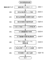
次に、上記ステップS20の特別図柄制御処理について、図6を参照しながら説明する。なお、図6は本実施の形態に係る特別図柄制御処理の処理手順を示すフローチャートである。   Next, the special symbol control process in step S20 will be described with reference to FIG. FIG. 6 is a flowchart showing the procedure of the special symbol control process according to the present embodiment.

ステップS20−1において、メインCPU201は、制御状態フラグをロードする処理を実行する。なお、制御状態フラグとは、特別図柄ゲームにおける遊技の状態を示すフラグである。メインCPU201は、この制御状態フラグに基づいて、ステップS20−2乃至ステップS20−10における各処理を実行するか否かを判別する。   In step S20-1, the main CPU 201 executes a process of loading a control state flag. The control state flag is a flag indicating a game state in the special symbol game. The main CPU 201 determines whether or not to execute each process in step S20-2 to step S20-10 based on this control state flag.

ステップS20−2において、メインCPU201は、詳細については後述する特別図柄記憶チェック処理(図7参照)を行う。ここでは、主に、大当たり遊技を実行するか否かを抽選する処理が行われる。そして、この抽選処理の結果に応じて、特別図柄表示器24に停止表示される特別図柄、当該特別図柄の変動表示パターン、変動表示時間等の決定が行われる。   In step S20-2, the main CPU 201 performs a special symbol storage check process (see FIG. 7) described later for details. Here, mainly, a process of drawing lots whether or not to execute the jackpot game is performed. Then, according to the result of the lottery process, the special symbol stopped and displayed on the special symbol display 24, the variation display pattern of the special symbol, the variation display time, and the like are determined.

ステップS20−3において、メインCPU201は、制御状態フラグが特別図柄変動表示時間管理を示す値(01)であり、且つ変動表示時間がセットされた待ち時間タイマの値が“0”である場合は、特別図柄の変動表示を終了させるために特別図柄表示時間管理を示す値(02)を制御状態フラグにセットするとともに、確定後待ち時間(例えば、1秒)を待ち時間タイマにセットする。なお、変動表示時間が終了した場合は、ステップS20−2にて決定された特別図柄の停止態様が特別図柄表示器24に停止表示される。   In step S20-3, the main CPU 201 determines that the control state flag is a value (01) indicating special symbol variation display time management and the value of the waiting time timer in which the variation display time is set is “0”. In order to end the variation display of the special symbol, a value (02) indicating special symbol display time management is set in the control state flag, and a waiting time after determination (for example, 1 second) is set in the waiting time timer. When the variable display time is over, the special symbol stop mode determined in step S20-2 is stopped and displayed on the special symbol display 24.

ステップS20−4において、メインCPU201は、制御状態フラグが特別図柄表示時間管理処理を示す値(02)であり、また、確定後待ち時間がセットされた待ち時間タイマの値が“0”であり、さらに、上記ステップS20−2の特別図柄チェック処理における大当たり抽選処理(詳細については後述する)で行われた大当たり抽選に当選した場合には、大当たり遊技の制御を開始するために大当たり開始インターバル管理処理を示す値(03)を制御状態フラグにセットするとともに、高確率フラグ及び変動短縮フラグに(00)をセットする。そして、大当たり開始インターバルに対応する時間(例えば、10秒)を待ち時間タイマにセットして特別図柄表示時間管理処理を終了する。   In step S20-4, the main CPU 201 indicates that the control state flag is a value (02) indicating the special symbol display time management process, and the value of the waiting time timer in which the waiting time after determination is set is “0”. In addition, when the jackpot lottery performed in the jackpot lottery process (details will be described later) in the special symbol check process in step S20-2 is won, the jackpot start interval management is performed to start the control of the jackpot game. A value (03) indicating processing is set in the control state flag, and (00) is set in the high probability flag and the fluctuation shortening flag. Then, the time corresponding to the jackpot start interval (for example, 10 seconds) is set in the waiting time timer, and the special symbol display time management process is ended.

また、メインCPU201は、上記大当たり抽選処理で行われた大当たり抽選にはずれた場合には、特別図柄ゲーム終了処理を示す値(08)を制御状態フラグにセットして特別図柄表示時間管理処理を終了する。   When the main CPU 201 deviates from the jackpot lottery performed in the jackpot lottery process, the main CPU 201 sets the value (08) indicating the special symbol game end process to the control state flag and ends the special symbol display time management process. To do.

ステップS20−5において、メインCPU201は、制御状態フラグが大当たり開始インターバル管理を示す値(03)であり、且つ大当たり開始インターバルに対応する時間がセットされた待ち時間タイマの値が“0”であるか否かを確認し、当該条件を満たしていない場合には、当該ステップを終了する。   In step S20-5, the main CPU 201 sets the control state flag to a value (03) indicating the jackpot start interval management, and the value of the waiting time timer in which the time corresponding to the jackpot start interval is set is “0”. Whether or not the condition is satisfied, the step is terminated.

上記条件を満たしている場合は、メインCPU201は、当該ステップにおいて大入賞装置開放回数カウンタに”1”を加算するとともに、大入賞装置15の扉15aを開放するように大入賞装置ソレノイド72Sを制御する。これにより、大入賞装置15が遊技球を受け入れ易い開状態となるラウンド動作の制御が開始され、遊技球が通過領域を通過可能となる。   If the above condition is satisfied, the main CPU 201 adds “1” to the winning device opening number counter in the step and controls the winning device solenoid 72S to open the door 15a of the winning device 15. To do. As a result, the control of the round operation in which the winning device 15 is in an open state in which it is easy to accept the game ball is started, and the game ball can pass through the passing area.

次に、メインCPU201は、大入賞装置開放中を示す値(04)を制御状態フラグにセットするとともに、開放上限時間(例えば、30秒)を大入賞装置開放時間タイマにセットする。   Next, the main CPU 201 sets a value (04) indicating that the winning device is open to the control state flag, and sets an opening upper limit time (for example, 30 seconds) to the winning device opening time timer.

ステップS20−6において、メインCPU201は、制御状態フラグに大入賞装置開放中を示す値(04)がセットされているか否かを確認し、大入賞装置開放中を示す値(04)がセットされていない場合には、当該ステップを終了する。一方、大入賞装置開放中を示す値(04)がセットされている場合には、次に開放上限時間がセットされた大入賞装置開放時間タイマの値が“0”であるという条件、または大入賞装置15に遊技球が10個以上入球したという条件の何れかが成立しているか否かを確認する。そして、2つの条件のうち、いずれかの条件が成立している場合、メインCPU201は、大入賞装置15の扉15aを閉じるように大入賞装置ソレノイド72Sを制御する。これにより、大入賞装置15は閉状態となりラウンド動作が終了する。   In step S20-6, the main CPU 201 confirms whether or not a value (04) indicating that the big winning device is open is set in the control state flag, and a value (04) indicating that the big winning device is open is set. If not, the step ends. On the other hand, when the value (04) indicating that the big winning device is being opened is set, the condition that the value of the big winning device opening time timer that is set to the next upper opening limit time is “0” or large It is confirmed whether any of the conditions that 10 or more game balls have entered the winning device 15 is satisfied. When one of the two conditions is satisfied, the main CPU 201 controls the big winning device solenoid 72S so as to close the door 15a of the big winning device 15. As a result, the special winning device 15 is closed and the round operation is completed.

また、メインCPU201は、当該ステップにおいて大入賞装置内残留球監視を示す値(05)を制御状態フラグにセットするとともに、大入賞装置内残留球監視時間(例えば、1秒)を待ち時間タイマにセットする。   In addition, the main CPU 201 sets a value (05) indicating monitoring of the winning ball in the winning device in the control step flag in the step, and sets the remaining winning ball monitoring time (for example, 1 second) in the waiting time timer. set.

ステップS20−7において、メインCPU201は、制御状態フラグが大入賞装置内残留球監視を示す値(05)であり、且つ大入賞装置内残留球監視時間がセットされた待ち時間タイマの値が“0”であるか否かを確認する。   In step S20-7, the main CPU 201 determines that the control state flag is a value (05) indicating monitoring of the winning ball in the winning device and the value of the waiting time timer in which the monitoring time in the winning device is set is “ Check if it is 0 ".

そして、メインCPU201は、上記何れの条件も満たす場合には、次に大入賞装置開放回数カウンタの値が“15”以上(最終ラウンド)であるという条件が成立しているか否かを確認する。なお、大入賞装置開放回数カウンタとは、大当たり遊技におけるラウンド数をカウントするものである。   Then, when any of the above conditions is satisfied, the main CPU 201 checks whether or not the condition that the value of the winning device opening number counter is “15” or more (final round) is satisfied. Note that the big prize device opening number counter counts the number of rounds in the big hit game.

また、メインCPU201は、大入賞装置開放回数カウンタの値が“15”以上(最終ラウンド)である場合には、大当たり終了インターバルを示す値(07)を制御状態フラグにセットするとともに、大入賞装置開放回数カウンタに”0”をセットする。そして、大当たり終了インターバルに対応する時間を待ち時間タイマにセットする。   Further, when the value of the big winning device opening number counter is “15” or more (final round), the main CPU 201 sets a value (07) indicating the big hit end interval in the control state flag, and also wins the big winning device. Set “0” to the number of times of opening counter. Then, the time corresponding to the jackpot end interval is set in the waiting time timer.

一方、メインCPU201は、大入賞装置開放回数カウンタの値が“15”以上(最終ラウンド)ではない場合には、大入賞装置再開放待ち時間管理を示す値(06)を制御状態フラグにセットするとともに、ラウンド間インターバルに対応する時間を待ち時間タイマにセットする。   On the other hand, the main CPU 201 sets a value (06) indicating management of waiting time for reopening a big winning device (06) in the control state flag when the value of the big winning device opening number counter is not “15” or more (final round). At the same time, the time corresponding to the interval between rounds is set in the waiting time timer.

ステップS20−8において、メインCPU201は、制御状態フラグに大入賞装置再開放待ち時間を示す値(06)がセットされているか否かを確認し、大入賞装置再開放待ち時間を示す値(06)がセットされていない場合には、当該ステップを終了する。一方、大入賞装置再開放待ち時間を示す値(06)がセットされている場合には、次にラウンド間インターバルに対応する時間がセットされた待ち時間タイマの値が“0”であるか否かを確認する。そして、当該待ち時間タイマの値が“0”である場合には、メインCPU201は、大入賞装置開放回数カウンタの値に“1”を加算するとともに、大入賞装置15の扉15aを開放するように大入賞装置ソレノイド72Sを制御する。これにより、大入賞装置15は開状態となりラウンド動作の制御が開始される。そして、次に大入賞装置開放中を示す値(04)を制御状態フラグにセットするとともに、開放上限時間として所定時間(例えば、30秒)を大入賞装置開放時間タイマにセットする。   In step S20-8, the main CPU 201 confirms whether or not the value (06) indicating the large winning device reopening waiting time is set in the control state flag, and the value (06) indicating the large winning device reopening waiting time. ) Is not set, the step ends. On the other hand, when the value (06) indicating the waiting time for reopening the big winning device is set, whether or not the value of the waiting time timer in which the time corresponding to the interval between rounds is set next is “0”. To check. When the value of the waiting time timer is “0”, the main CPU 201 adds “1” to the value of the big winning device opening number counter and opens the door 15 a of the big winning device 15. The large winning device solenoid 72S is controlled. As a result, the special winning device 15 is opened and the control of the round operation is started. Then, a value (04) indicating that the big winning device is open is set in the control state flag, and a predetermined time (for example, 30 seconds) is set in the big winning device opening time timer as the upper limit time for opening.

ステップS20−9において、メインCPU201は、制御状態フラグが大当たり終了インターバル処理を示す値(07)であり、大当たり終了インターバルに対応する時間がセットされた待ち時間タイマの値が“0”である場合は、特別図柄ゲーム終了処理を示す値(08)を制御状態フラグにセットする。   In step S20-9, the main CPU 201 determines that the control state flag is a value (07) indicating the jackpot end interval process, and the value of the waiting time timer in which the time corresponding to the jackpot end interval is set is “0”. Sets the value (08) indicating the special symbol game end process to the control state flag.

また、遊技状態制御手段であるメインCPU201は、ステップS20−2−5(図7)にて高確率状態が決定されたか否かを確認する。確認の結果、高確率状態が決定された場合には、高確率状態の制御を開始するために遊技状態フラグに高確率状態を示す値(01)をセットする。   Further, the main CPU 201 which is the game state control means confirms whether or not the high probability state is determined in step S20-2-5 (FIG. 7). As a result of the confirmation, if a high probability state is determined, a value (01) indicating the high probability state is set in the gaming state flag in order to start control of the high probability state.

さらに、メインCPU201は、時短状態の制御を開始するために変動短縮フラグに時短状態を示す値(33)をセットする。これにより、単位時間あたりにおける始動口18への入賞遊技球数が相対的に増加する可能性の高い(可変翼18a,18bが開状態となる時間の総和が相対的に大きくなる)時短状態に移行する。ここで、時短状態の制御は、特別図柄の変動表示が所定回数(例えば、100回)行われるまで、もしくは大当たり遊技に当選するまで継続される。   Further, the main CPU 201 sets a value (33) indicating the time reduction state in the fluctuation reduction flag in order to start control of the time reduction state. Thereby, there is a high possibility that the number of winning game balls to the start opening 18 per unit time is relatively increased (the total time during which the variable wings 18a and 18b are opened is relatively large). Transition. Here, the control in the short-time state is continued until the special symbol variation display is performed a predetermined number of times (for example, 100 times) or until the jackpot game is won.

このように、本実施の形態における時短状態は、大当たりに当選し、且つ大当たり遊技が終了した場合に、開始されるようになっている。但し、本発明においては、時短状態の開始条件はこれに限られない。また、大当たり遊技の終了後に時短状態を開始させるか否かは、抽選により決定されるようになっていてもよい。   As described above, the time saving state in the present embodiment is started when the jackpot is won and the jackpot game ends. However, in the present invention, the start condition of the time reduction state is not limited to this. Further, whether or not to start the time-saving state after the end of the jackpot game may be determined by lottery.

ステップS20−10において、メインCPU201は、制御状態フラグが特別図柄ゲーム終了を示す値(08)である場合に、保留記憶カウンタから“1”を減算する。また、メインCPU201は、保留記憶領域(“1”〜“4”)にそれぞれ記憶されているデータを、それぞれ保留記憶領域(“0”〜“3”)にシフトさせるとともに、特別図柄記憶チェックを示す値(00)を制御状態フラグにセットする。   In step S20-10, the main CPU 201 subtracts “1” from the holding storage counter when the control state flag is a value (08) indicating the end of the special symbol game. The main CPU 201 shifts the data stored in the reserved storage areas (“1” to “4”) to the reserved storage areas (“0” to “3”), respectively, and performs a special symbol storage check. The indicated value (00) is set in the control state flag.

[特別図柄記憶チェック処理]   [Special symbol memory check processing]

次に、上記ステップS20−2の特別図柄記憶チェック処理について、図7を参照しながら説明する。なお、図7は本実施の形態に係る特別図柄記憶チェック処理の処理手順を示すフローチャートである。   Next, the special symbol memory check process in step S20-2 will be described with reference to FIG. FIG. 7 is a flowchart showing the procedure of the special symbol storage check process according to the present embodiment.

ステップS20−2−1において、メインCPU201は、制御状態フラグが特別図柄記憶チェックを示す値(00)であるか否かを確認し、この確認の結果、制御状態フラグが特別図柄記憶チェックを示す値(00)である場合には、ステップS20−2−2の処理に移り、一方、制御状態フラグが特別図柄記憶チェックを示す値(00)でない場合は、この特別図柄記憶チェック処理を終了する。   In step S20-2-1, the main CPU 201 confirms whether or not the control state flag is a value (00) indicating a special symbol storage check, and as a result of the confirmation, the control state flag indicates a special symbol storage check. When the value is (00), the process proceeds to step S20-2-2. On the other hand, when the control state flag is not the value (00) indicating the special symbol storage check, the special symbol storage check process is terminated. .

ステップS20−2−2において、メインCPU201は、保留記憶カウンタの値が“0”であるか否か(すなわち、保留記憶領域(“0”〜“4”)に記憶された保留記憶の数が“0”であるか否か)を確認し、この確認の結果、保留記憶カウンタの値が“0”である場合にはステップS20−2−3の処理に移り、一方、保留記憶カウンタの値が“0”でない場合はステップS20−2−4の処理に移る。   In step S20-2-2, the main CPU 201 determines whether or not the value of the reserved storage counter is “0” (that is, the number of reserved memories stored in the reserved storage area (“0” to “4”)). If the value of the hold storage counter is “0” as a result of the check, the process proceeds to step S20-2-3, while the value of the hold storage counter is If is not "0", the process proceeds to step S20-2-4.

ステップS20−2−3において、メインCPU201は、デモ演出画像の表示を実行するように指示する待機状態コマンドを生成し、セットする。なお、上記待機状態コマンドは、遊技状態が待機状態(特別図柄表示器24における特別図柄の変動表示の動作が行われておらず、大当たり遊技中でもなく、保留記憶もない状態)の場合に生成される。   In step S20-2-3, the main CPU 201 generates and sets a standby state command for instructing to display a demonstration effect image. The standby state command is generated when the gaming state is the standby state (the state where the special symbol display unit 24 does not perform the special symbol variation display operation, the jackpot game is not performed, and there is no reserved memory). The

ステップS20−2−4において、メインCPU201は、特別図柄変動表示時間管理を示す値(01)を制御状態フラグにセットする。   In step S20-2-4, the main CPU 201 sets a value (01) indicating special symbol variation display time management in the control state flag.

ステップS20−2−5において、大当たり抽選手段であるメインCPU201は、保留記憶領域(“0”)に記憶された保留記憶に含まれる大当たり抽選用乱数値と、大当たり抽選テーブル(図13)とを基にして、遊技者に有利な大当たり遊技を実行するか否かの大当たり抽選を行う。   In step S20-2-5, the main CPU 201, which is a jackpot lottery means, stores the jackpot lottery random value included in the hold storage stored in the hold storage area ("0") and the jackpot lottery table (FIG. 13). A jackpot lottery is performed based on whether or not a jackpot game advantageous to the player is executed.

例えば、メインCPU201は、非高確率状態の場合(遊技状態フラグに非高確率状態を示す値(00)がセットされている場合)においては、大当たり抽選用乱数値が7のときに大当たりと判断する。また、メインCPU201は、高確率状態の場合(遊技状態フラグに高確率状態を示す値(01)がセットされている場合)においては、3、5、7、11、13のときに大当たりと判断する。このように、本実施の形態では、高確率状態時においては、非高確率状態時と比べて、大当たりとなる乱数値が多く設定されており、大当たりに当選し易く(つまり、遊技者に有利に)なっている。   For example, when the main CPU 201 is in a non-high probability state (when the gaming state flag is set to a value (00) indicating a non-high probability state), the main CPU 201 determines that the big winning lottery random number value is 7 To do. Further, the main CPU 201 determines that the jackpot is 3, 5, 7, 11, 13 in the case of a high probability state (when the value (01) indicating the high probability state is set in the gaming state flag). To do. As described above, in the present embodiment, in the high probability state, compared to the non-high probability state, a large number of random numbers that are jackpots are set, and it is easy to win the jackpot (that is, advantageous to the player). It has become.

ステップS20−2−6において、メインCPU201は、ステップS20−2−5にて行われた大当たり抽選の結果が遊技状態を大当たり遊技とするものであるか否かを確認する。そして、メインCPU201は、大当たり抽選の結果が遊技状態を大当たり遊技とするものである場合(大当たりに当選した場合)には、ステップS20−2−8の処理に移る。一方、大当たり抽選の結果が遊技状態を大当たり遊技とするものでない場合(大当たりに当選しなかった場合)には、ステップS20−2−7の処理に移る。   In step S20-2-6, the main CPU 201 confirms whether or not the result of the jackpot lottery performed in step S20-2-5 is that the gaming state is a jackpot game. Then, when the result of the jackpot lottery indicates that the gaming state is the jackpot game (when the jackpot is won), the main CPU 201 proceeds to the process of step S20-2-8. On the other hand, when the jackpot lottery result does not indicate that the gaming state is the jackpot game (when the jackpot is not won), the process proceeds to step S20-2-7.

ステップS20−2−7において、特別図柄決定手段であるメインCPU201は、ステップS20−2−5の大当たり抽選結果及び図13に示す大当たり抽選テーブルに基づいて、特別図柄表示器24に停止表示させる特別図柄を決定する。具体的には、メインCPU201は、記号図柄「−」を特別図柄表示器24に停止表示させる特別図柄として決定し、次に、当該特別図柄「−」を示す停止図柄コマンドを生成してセットする。本ステップの処理が終了した場合には、ステップS20−2−9に処理を移行する。   In step S20-2-7, the main CPU 201, which is a special symbol determination means, performs a special stop display on the special symbol display 24 based on the jackpot lottery result in step S20-2-5 and the jackpot lottery table shown in FIG. Determine the design. Specifically, the main CPU 201 determines the symbol symbol “-” as a special symbol to be stopped and displayed on the special symbol display 24, and then generates and sets a stop symbol command indicating the special symbol “-”. . When the process in this step is completed, the process proceeds to step S20-2-9.

ステップS20−2−8において、遊技状態決定手段及び特別図柄決定手段であるメインCPU201は、ステップS20−2−5の大当たり抽選結果、保留記憶領域(“0”)に記憶された保留記憶に含まれる大当たり図柄乱数値及び図13のテーブルに基づいて、大当たり遊技の終了後における遊技状態及び特別図柄表示器24に停止表示させる特別図柄を決定する。   In step S20-2-8, the main CPU 201, which is the gaming state determination means and the special symbol determination means, is included in the holding storage stored in the holding storage area (“0”), the jackpot lottery result of step S20-2-5. Based on the jackpot symbol random number value and the table of FIG. 13, the game state after the jackpot game is ended and the special symbol to be stopped and displayed on the special symbol display 24 are determined.

例えば、メインCPU201は、上記大当たり図柄乱数値が”1”である場合には、大当たり遊技の終了後における遊技状態として高確率状態を決定するとともに、数字図柄「1」を特別図柄表示器24に停止表示させる特別図柄として決定する。また、メインCPU201は、上記大当たり図柄乱数値が”2”である場合には、大当たり遊技の終了後における遊技状態として非高確率状態を決定するとともに、数字図柄「2」を特別図柄表示器24に停止表示させる特別図柄として決定する。   For example, when the jackpot symbol random number value is “1”, the main CPU 201 determines a high probability state as the gaming state after the jackpot game is ended, and sets the number symbol “1” to the special symbol indicator 24. It is determined as a special symbol to be stopped and displayed. Further, when the jackpot symbol random number is “2”, the main CPU 201 determines a non-high probability state as the gaming state after the jackpot game ends, and displays the numeric symbol “2” on the special symbol indicator 24. Is determined as a special symbol to be stopped and displayed.

ここで、遊技状態決定手段は、大当たり遊技の終了後における遊技状態を、50%の確率で高確率状態に決定している。但し、本発明では、遊技状態決定手段が高確率状態を決定する確率はこれに限られない。また、遊技状態決定手段が高確率状態を決定する確率を、遊技状態に応じて異ならせる(具体的には、遊技状態決定手段が高確率状態を決定する確率を、遊技状態フラグに高確率状態を示す値(01)がセットされている場合と非高確率状態を示す値(00)がセットされている場合とで異ならせる)ようにしてもよい。   Here, the game state determination means determines the game state after the end of the jackpot game to a high probability state with a probability of 50%. However, in the present invention, the probability that the gaming state determination means determines the high probability state is not limited to this. Further, the probability that the gaming state determination means determines the high probability state is made different depending on the gaming state (specifically, the probability that the gaming state determination means determines the high probability state is set in the gaming state flag as a high probability state. Or a value (01) indicating a non-high probability state may be set differently).

次に、メインCPU201は、決定した特別図柄を示す停止図柄コマンドを生成してセットする。本ステップの処理が終了した場合には、ステップS20−2−9に処理を移行する。   Next, the main CPU 201 generates and sets a stop symbol command indicating the determined special symbol. When the process in this step is completed, the process proceeds to step S20-2-9.

ステップS20−2−9において、予告演出実行決定手段であるメインCPU201は、実行する演出表示パターンを決定する処理を行う。   In step S20-2-9, the main CPU 201, which is a notice effect execution determination unit, performs a process of determining an effect display pattern to be executed.

具体的には、メインCPU201は、保留記憶領域(“0”)に記憶された保留記憶に含まれる乱数値(大当たり抽選用乱数値、リーチ演出用乱数値、予告演出乱数値)と、大当たり予告演出実行決定テーブル(図14)とを基にして、実行する演出表示パターンを決定する。   Specifically, the main CPU 201 determines the random number values (random number for jackpot lottery, random number for reach effect, random number value for notice effect) included in the hold storage stored in the hold storage area (“0”), and the jackpot notice. An effect display pattern to be executed is determined based on the effect execution determination table (FIG. 14).

例えば、予告演出実行決定手段であるメインCPU201は、抽出された大当たり抽選用乱数値が大当たり抽選に当選する乱数値である場合(具体的には、非高確率状態時においては、大当たり抽選用乱数値が7である場合、一方、高確率状態時においては、大当たり抽選用乱数値が3,5,7,11,13の何れかである場合)には、予告演出乱数値が0〜29の範囲であれば大当たり予告パターンに応じた演出表示を実行する旨を決定し、予告演出乱数値が30〜59の範囲であれば、はずれ予告パターンに応じた演出表示を実行する旨を決定し、予告演出乱数値が60〜89の範囲であれば移動演出パターンに応じた演出表示を実行する旨を決定し、予告演出乱数値が90〜99の範囲であれば、通常演出パターンに応じた演出表示を実行する旨を決定する。   For example, the main CPU 201 serving as the notice effect execution determining means, when the extracted jackpot lottery random value is a random value for winning the jackpot lottery (specifically, in the non-high probability state, the jackpot lottery randomness) When the numerical value is 7, on the other hand, in the high probability state, when the random number value for jackpot lottery is any one of 3, 5, 7, 11, and 13), the notice effect random number value is 0 to 29 If it is within the range, it is determined that the effect display according to the jackpot notice pattern is executed, and if the notice effect random number is in the range of 30 to 59, it is determined that the effect display according to the off-notice notice pattern is executed, If the notice effect random number is in the range of 60 to 89, it is determined that the effect display corresponding to the movement effect pattern is executed. If the notice effect random number is in the range of 90 to 99, the effect according to the normal effect pattern is determined. Display To determine the effect that line.

また、抽出された大当たり抽選用乱数値が大当たり抽選にはずれる乱数値であり(具体的には、非高確率状態時においては、大当たり抽選用乱数値が7以外である場合、一方、高確率状態時においては、大当たり抽選用乱数値が3,5,7,11,13以外である場合)、且つリーチ演出用乱数値が0〜79の範囲であるとき(リーチ変動が実行されない値であるとき)には、予告演出乱数値が0〜9の範囲であれば大当たり予告パターンに応じた演出表示を実行する旨を決定し、予告演出乱数値が10〜79の範囲であれば、はずれ予告パターンに応じた演出表示を実行する旨を決定し、予告演出乱数値が80〜89の範囲であれば移動演出パターンに応じた演出表示を実行する旨を決定し、予告演出乱数値が90〜99の範囲であれば、通常演出パターンに応じた演出表示を実行する旨を決定する。   In addition, the extracted jackpot lottery random number value is a random number value that deviates from the jackpot lottery (specifically, in the non-high probability state, if the jackpot lottery random number value is other than 7, the high probability state Sometimes, when the jackpot lottery random value is other than 3, 5, 7, 11, 13 and the reach effect random value is in the range of 0 to 79 (when reach variation is not performed) ) Determines that the effect display according to the jackpot notice pattern is executed if the notice effect random number value is in the range of 0 to 9, and if the notice effect random number value is in the range of 10 to 79, the off notice notice pattern is determined. The effect display corresponding to the movement effect pattern is determined to be executed if the notice effect random number is in the range of 80 to 89, and the notice effect random value is 90 to 99. In the range To determine the effect that perform the effect display in accordance with the normal effect pattern.

また、抽出された大当たり抽選用乱数値が大当たり抽選にはずれる乱数値であり、且つリーチ演出用乱数値が80〜99の範囲であるとき(リーチ変動が実行される値であるとき)には、予告演出乱数値が0〜19の範囲であれば大当たり予告パターンに応じた演出表示を実行する旨を決定し、予告演出乱数値が20〜69の範囲であれば、はずれ予告パターンに応じた演出表示を実行する旨を決定し、予告演出乱数値が70〜89の範囲であれば移動演出パターンに応じた演出表示を実行する旨を決定し、予告演出乱数値が90〜99の範囲であれば、通常演出パターンに応じた演出表示を実行する旨を決定する。   Further, when the extracted jackpot lottery random value is a random number value that is out of the jackpot lottery and the reach effect random number value is in the range of 80 to 99 (when reach variation is executed), If the notice effect random number value is in the range of 0 to 19, it is determined that the effect display according to the jackpot notice pattern is executed. If the notice effect random number value is in the range of 20 to 69, the effect according to the off-notice notice pattern is determined. It is determined that display is to be executed, and if the notice effect random number is in the range of 70 to 89, it is determined that effect display according to the movement effect pattern is to be executed, and the notice effect random number is in the range of 90 to 99. For example, it is determined that the effect display according to the normal effect pattern is executed.

このように、本ステップでは、抽出された大当たり抽選用乱数値が大当たり抽選に当選する乱数値である場合には、30%の確率で大当たり予告パターンに応じた演出表示の実行が決定される。また、抽出された大当たり抽選用乱数値が大当たり抽選にはずれる乱数値であるときには、リーチ変動が実行されない場合であれば10%の確率で、リーチ変動が実行される場合であれば20%の確率で、それぞれ大当たり予告パターンに応じた演出表示の実行が決定される。   Thus, in this step, when the extracted jackpot lottery random value is a random value for winning the jackpot lottery, execution of the effect display according to the jackpot notice pattern is determined with a probability of 30%. Further, when the extracted jackpot lottery random number value is a random number value that deviates from the jackpot lottery, there is a 10% probability if reach variation is not executed, and a 20% probability if reach variation is executed. Thus, the execution of the effect display according to the jackpot notice pattern is determined.

つまり、本実施の形態では、大当たりに当選する場合やリーチ変動が実行される場合に、大当たり予告パターンに応じた演出が発生する確率が向上するようになっている。これによれば、大当たり予告パターンに応じた演出が実行されることによって、大当たりの当選やリーチ状態の発生を予告することができ、遊技者の期待感を高ぶらせることができる。   In other words, in the present embodiment, the probability that an effect corresponding to the jackpot notice pattern occurs when the jackpot is won or the reach variation is executed is improved. According to this, by performing the presentation according to the jackpot notice pattern, it is possible to notice the winning of the jackpot and the occurrence of the reach state, and it is possible to increase the player's expectation.

次に、メインCPU201は、決定した演出表示を実行する旨を示す予告演出実行コマンドを生成してセットする。例えば、メインCPU201は、大当たり予告パターンに応じた演出を実行する旨を決定した場合には、当該演出を示す予告演出実行コマンドを生成してセットし、移動演出パターンに応じた演出を実行する旨を決定した場合には、当該演出を示す予告演出実行コマンドを生成してセットする。本ステップの処理が終了した場合には、ステップS20−2−10に処理を移行する。   Next, the main CPU 201 generates and sets a notice effect execution command indicating that the determined effect display is executed. For example, when the main CPU 201 determines to execute an effect according to the jackpot notice pattern, the main CPU 201 generates and sets a notice effect execution command indicating the effect, and executes the effect according to the movement effect pattern. Is determined, a notice effect execution command indicating the effect is generated and set. When the process in this step is completed, the process proceeds to step S20-2-10.

ステップS20−2−10において、特別図柄変動表示パターン決定手段及び変動表示パターン決定手段であるメインCPU201は、特別図柄や装飾図柄の変動表示パターンや変動表示時間を決定する処理を行う。   In step S20-2-10, the main CPU 201, which is the special symbol variation display pattern determination unit and the variation display pattern determination unit, performs a process of determining the variation display pattern and variation display time of the special symbol and the decorative symbol.

まず、メインCPU201は、乱数発生器により0から99の範囲で発生した乱数のうち、一の乱数値を抽出する。次に、メインCPU201は、抽出した乱数値と、変動表示パターン決定テーブル(図15)とを基にして、特別図柄や装飾図柄の変動表示パターンや変動表示時間を決定する。   First, the main CPU 201 extracts one random number value from random numbers generated from 0 to 99 by a random number generator. Next, the main CPU 201 determines the variable display pattern and the variable display time of the special symbol and the decorative symbol based on the extracted random number value and the variable display pattern determination table (FIG. 15).

例えば、特別図柄変動表示パターン決定手段及び変動表示パターン決定手段であるメインCPU201は、ステップS20−2−5にて行われた大当たり抽選の結果がはずれであり、且つ抽出された乱数値が0から70の範囲に含まれるものであったときは、当該条件に応じた特別図柄の変動表示パターンを決定するとともに、装飾図柄の変動表示パターンとして「通常変動(はずれ)」を決定する(このとき、変動表示時間は、12(s)に決定される)。   For example, the main CPU 201 which is the special symbol variation display pattern determination unit and the variation display pattern determination unit is out of the result of the jackpot lottery performed in step S20-2-5, and the extracted random number value is 0. If it is included in the range of 70, a special symbol variation display pattern corresponding to the condition is determined, and a “normal variation (out)” is determined as a decoration symbol variation display pattern (at this time, The variable display time is determined to be 12 (s)).

また、メインCPU201は、大当たり抽選の結果がはずれであり、且つ抽出された乱数値が80から89の範囲に含まれるものであったときは、当該条件に応じた特別図柄の変動表示パターンを決定するとともに、装飾図柄の変動表示パターンとして「ノーマルリーチ変動(はずれ)」を決定する(このとき、変動表示時間は30(s)に決定される)。   Further, when the result of the big hit lottery is out of the range and the extracted random number value is included in the range of 80 to 89, the main CPU 201 determines a special symbol variation display pattern according to the condition. At the same time, “normal reach fluctuation (displacement)” is determined as the variation display pattern of the decorative design (at this time, the variation display time is determined to be 30 (s)).

また、メインCPU201は、大当たり抽選の結果がはずれであり、且つ抽出された乱数値が90から94の範囲に含まれるものであったときは、当該条件に応じた特別図柄の変動表示パターンを決定するとともに、装飾図柄の変動表示パターンとして「スーパーリーチ変動1(はずれ)」を決定する(このとき、変動表示時間は45(s)に決定される)。   Further, when the result of the big hit lottery is out of the range and the extracted random number value is included in the range of 90 to 94, the main CPU 201 determines a special symbol variation display pattern according to the condition. At the same time, “super reach variation 1 (displacement)” is determined as the variation display pattern of the decorative symbol (at this time, the variation display time is determined to be 45 (s)).

また、メインCPU201は、大当たり抽選の結果がはずれであり、且つ抽出された乱数値が95から99の範囲に含まれるものであったときは、当該条件に応じた特別図柄の変動表示パターンを決定するとともに、装飾図柄の変動表示パターンとして「スーパーリーチ変動2(はずれ)」を決定する(このとき、変動表示時間は55(s)に決定される)。   Further, when the result of the big hit lottery is out of the range and the extracted random number value is included in the range of 95 to 99, the main CPU 201 determines a special symbol variation display pattern according to the condition. At the same time, “super reach fluctuation 2 (displacement)” is determined as the decorative display variable display pattern (at this time, the variable display time is determined to be 55 (s)).

また、メインCPU201は、大当たり抽選の結果が当選であり、且つ抽出された乱数値が0から20の範囲に含まれるものであったときは、当該条件に応じた特別図柄の変動表示パターンを決定するとともに、装飾図柄の変動表示パターンとして「ノーマルリーチ変動(当たり)」を決定する(このとき、変動表示時間は30(s)に決定される)。   Also, the main CPU 201 determines a special symbol variation display pattern according to the condition when the result of the big win lottery is a win and the extracted random number value is included in the range of 0 to 20. At the same time, “normal reach fluctuation (winning)” is determined as the decorative display variation display pattern (at this time, the variation display time is determined to be 30 (s)).

また、メインCPU201は、大当たり抽選の結果が当選であり、且つ抽出された乱数値が21から50の範囲に含まれるものであったときは、当該条件に応じた特別図柄の変動表示パターンを決定するとともに、装飾図柄の変動表示パターンとして「スーパーリーチ変動1(当たり)」を決定する(このとき、変動表示時間は45(s)に決定される)。   Further, the main CPU 201 determines the variation display pattern of the special symbol according to the condition when the result of the big hit lottery is a win and the extracted random number value is included in the range of 21 to 50. At the same time, “super reach fluctuation 1 (per hit)” is determined as the decorative display variable display pattern (at this time, the variable display time is determined to be 45 (s)).

また、メインCPU201は、大当たり抽選の結果が当選であり、且つ抽出された乱数値が51から99の範囲に含まれるものであったときは、当該条件に応じた特別図柄の変動表示パターンを決定するとともに、装飾図柄の変動表示パターンとして「スーパーリーチ変動2(当たり)」を決定する(このとき、変動表示時間は55(s)に決定される)。   Further, when the result of the big hit lottery is a win and the extracted random number value is included in the range of 51 to 99, the main CPU 201 determines a special symbol variation display pattern according to the condition. At the same time, “super reach variation 2 (win)” is determined as the decorative symbol variation display pattern (at this time, the variation display time is determined to be 55 (s)).

そして、当該決定した装飾図柄の変動表示パターンや変動表示時間等を示す変動表示パターンコマンドを生成してセットする。   Then, a variation display pattern command indicating the variation display pattern and variation display time of the determined decorative design is generated and set.

ステップS20−2−11において、メインCPU201は、ステップS20−2−10の処理にて決定された変動表示時間を待ち時間タイマにセットする。   In step S20-2-11, the main CPU 201 sets the variable display time determined in the process of step S20-2-10 in the waiting time timer.

なお、特別図柄表示器24における特別図柄の変動表示は、ステップS20−2−11によってセットされた変動表示時間の間、ステップS20−2−10にて決定された特別図柄の変動表示パターンに従って行われる。変動表示時間が終了すると、変動表示される特別図柄は、ステップS20−2−7もしくはステップS20−2−8にて決定された特別図柄が表示された状態で停止する。   The special symbol variation display on the special symbol display 24 is performed according to the special symbol variation display pattern determined in step S20-2-10 during the variation display time set in step S20-2-11. Is called. When the variable display time is over, the special symbol displayed in a variable manner stops with the special symbol determined in step S20-2-7 or step S20-2-8 being displayed.

また、装飾図柄の変動表示は、ステップS20−2−11によってセットされた変動表示時間の間、ステップS20−2−10にて生成された変動動表示パターンコマンドに基づいて行われる。変動表示時間が終了すると、変動表示される装飾図柄は、ステップS20−2−7もしくはステップS20−2−8にて生成された停止図柄コマンドを基にサブCPU(装飾図柄決定手段)301により決定された装飾図柄、が表示された状態で停止する。   Further, the decorative symbol variation display is performed based on the variation dynamic display pattern command generated in step S20-2-10 during the variation display time set in step S20-2-11. When the variable display time is over, the decorative symbol to be variable displayed is determined by the sub CPU (decorative symbol determining means) 301 based on the stop symbol command generated in step S20-2-7 or step S20-2-8. It stops in the state where the decorated design is displayed.

ステップS20−2−12において、メインCPU201は、今回の特別図柄記憶チェック処理に用いられた乱数値などを、所定の記憶領域から消去する。   In step S20-2-12, the main CPU 201 erases the random number value and the like used for the special symbol storage check process this time from a predetermined storage area.

[副制御回路処理]   [Sub-control circuit processing]

次に、副制御回路300によるメイン処理、及び主制御回路200からのコマンドを受信したことを契機としてメイン処理に割込むように実行されるコマンド受信割込処理について説明する。図8は本発明の実施の形態に係るコマンド受信割込処理の処理手順を示すフローチャートであり、図9は本発明の実施の形態に係る遊技機の副制御回路によるメイン処理の処理手順を示すフローチャートである。   Next, the main process by the sub-control circuit 300 and the command reception interrupt process executed so as to interrupt the main process when receiving a command from the main control circuit 200 will be described. FIG. 8 is a flowchart showing a processing procedure of command reception interrupt processing according to the embodiment of the present invention, and FIG. 9 shows a processing procedure of main processing by the sub-control circuit of the gaming machine according to the embodiment of the present invention. It is a flowchart.

最初に、コマンド受信割込処理について、図8を参照して説明する。このコマンド受信割込処理は、副制御回路300が主制御回路200からコマンドを受信する毎に発生するようになっている。   First, the command reception interrupt process will be described with reference to FIG. This command reception interrupt process is generated every time the sub control circuit 300 receives a command from the main control circuit 200.

ステップS201において、サブCPU301は、現在実行中のプロセス(後述するメイン処理)を中断するために、レジスタに格納されている情報を退避させる。   In step S201, the sub CPU 301 saves the information stored in the register in order to interrupt the currently executing process (main process described later).

ステップS202において、サブCPU301は、コマンド入力ポート304を介して受信したメインCPU201からのコマンド(例えば、変動表示パターンコマンド、予告演出実行コマンド、停止図柄コマンド、待機状態コマンドなど)を、ワークRAM303の受信バッファ領域へ格納する。   In step S <b> 202, the sub CPU 301 receives a command (for example, a change display pattern command, a notice effect execution command, a stop symbol command, a standby state command, etc.) received from the main CPU 201 via the command input port 304. Store in the buffer area.

ステップS203において、サブCPU301は、ステップS201で退避させた情報をレジスタに復帰させる。これにより、中断されているプロセスは再開可能となる。   In step S203, the sub CPU 301 restores the information saved in step S201 to the register. As a result, the suspended process can be resumed.

次に、本実施の形態の副制御回路300のメイン処理について、図9を参照しながら説明する。   Next, the main processing of the sub control circuit 300 of this embodiment will be described with reference to FIG.

ステップS210において、サブCPU301は、各種設定を初期化する初期化処理を実行する。   In step S210, the sub CPU 301 executes an initialization process for initializing various settings.

ステップS220において、サブCPU301は、詳細については後述するコマンド解析処理(図10参照)を実行する。当該ステップにおいては、主に、受信バッファに格納されたコマンドを読み出す処理等が行われる。   In step S220, the sub CPU 301 executes a command analysis process (see FIG. 10) described later for details. In this step, processing for reading out a command stored in the reception buffer is mainly performed.

ステップS230において、サブCPU301は、後述するコマンド解析処理(図10)等においてセットした演出データを確認し、当該セットされた演出データに基づいて画像表示制御処理を実行する。   In step S230, the sub CPU 301 confirms the effect data set in a command analysis process (FIG. 10) described later, and executes an image display control process based on the set effect data.

また、表示制御手段であるサブCPU301は、ステップS220−4(図10)において変動表示パターンコマンドに対応する演出データがセットされた場合、セットされた演出データに含まれる態様に従った装飾図柄の変動表示を行うように、VDP305aに指示するためのデータを経時的に変化させる。VDP305aが所定時間ごとに送信される上記指示を実行することにより、液晶表示装置21の装飾図柄表示領域21bにおいて、ステップS20−2−10(図7)にて決定された変動表示時間の間、セットされた演出データに応じた装飾図柄の変動表示が行われる。   In addition, when the effect data corresponding to the variable display pattern command is set in step S220-4 (FIG. 10), the sub CPU 301 as the display control means displays the decorative design according to the mode included in the set effect data. The data for instructing the VDP 305a is changed over time so as to display the fluctuation. By executing the above instruction transmitted by VDP 305a every predetermined time, in the decorative symbol display area 21b of the liquid crystal display device 21, during the variable display time determined in step S20-2-10 (FIG. 7), The decorative symbols are displayed in a variable manner according to the set effect data.

例えば、サブCPU301は、コマンド解析処理(図10)において、スーパーリーチ変動1(はずれ)を示す変動表示パターンコマンドに対応する演出データがセットされた場合には、45(s)の間、スーパーリーチ変動1に対応する装飾図柄の変動表示を実行する。   For example, in the command analysis process (FIG. 10), when the effect data corresponding to the variation display pattern command indicating the super reach variation 1 (out of) is set, the sub CPU 301 performs the super reach for 45 (s). Decorative display variation display corresponding to variation 1 is executed.

上記変動表示が終了した後は、後述するステップS220−4にて決定された装飾図柄が停止表示される。   After the change display is completed, the decorative symbols determined in step S220-4 described later are stopped and displayed.

また、演出表示制御手段であるサブCPU301は、後述するコマンド解析処理のステップS220−6(図10)において、大当たり予告パターンに応じた演出表示を実行させるための演出データがセットされた場合には、当該演出データに含まれる態様に従った演出表示を行うように、VDP305aに指示するためのデータを経時的に変化させる。VDP305aが所定時間ごとに送信される上記指示を実行することにより、液晶表示装置21の装飾図柄表示領域21bにおいて、後述するステップS220−7(図10)にてセットされた予告演出の実行時間の間、セットされた演出データに応じた演出表示が行われる。   Further, the sub CPU 301 as the effect display control means, when the effect data for executing the effect display according to the jackpot notice pattern is set in step S220-6 (FIG. 10) of the command analysis process described later. The data for instructing the VDP 305a is changed with time so that the effect display according to the aspect included in the effect data is performed. By executing the above instruction transmitted by the VDP 305a every predetermined time, the execution time of the notice effect set in step S220-7 (FIG. 10) to be described later is displayed in the decorative symbol display area 21b of the liquid crystal display device 21. In the meantime, effect display according to the set effect data is performed.

ステップS240において、サブCPU 301は、音声制御処理を実行する。   In step S240, the sub CPU 301 executes voice control processing.

具体的には、音声制御処理においてサブCPU301は、ステップS220でセットした演出データに、音声に関する演出データが含まれているか否かを確認する。確認の結果、音声に関する演出データが含まれている場合には、当該演出データ(以下、「音声演出データ」という)を音声制御回路306に送る。音声制御回路306は、音声演出データに基づいて、スピーカ8a,8bに、例えば、所定の遊技状態を遊技者に報知するための音信号を出力させる。   Specifically, in the sound control process, the sub CPU 301 confirms whether or not the effect data related to the sound is included in the effect data set in step S220. As a result of the confirmation, if the production data related to the voice is included, the production data (hereinafter referred to as “voice production data”) is sent to the voice control circuit 306. The voice control circuit 306 causes the speakers 8a and 8b to output, for example, a sound signal for notifying the player of a predetermined gaming state based on the voice effect data.

ステップS250において、サブCPU301は、ランプ制御処理を実行する。   In step S250, the sub CPU 301 executes lamp control processing.

具体的には、ランプ制御処理においてサブCPU301は、ステップS220でセットした演出データに、ランプやLEDに関する演出データが含まれているか否かを確認する。確認の結果、ランプやLEDに関する演出データが含まれている場合には、当該演出データ(以下、「ランプ演出データ」という)をランプ制御回路307に送る。ランプ制御回路307は、ランプ演出データに基づいて、装飾ランプ39aに、例えば、所定の点灯・消灯パターンに従った点灯・消灯を行わせる。   Specifically, in the lamp control process, the sub CPU 301 confirms whether or not the effect data related to the lamp and the LED is included in the effect data set in step S220. As a result of the confirmation, if the effect data related to the lamp or LED is included, the effect data (hereinafter referred to as “lamp effect data”) is sent to the lamp control circuit 307. Based on the lamp effect data, the lamp control circuit 307 causes the decorative lamp 39a to turn on / off according to a predetermined lighting / extinguishing pattern, for example.

このメイン処理においては、上述したステップS220からステップS250までの処理が繰り返し行われる。   In this main process, the processes from step S220 to step S250 described above are repeated.

[コマンド解析処理]   [Command analysis processing]

次に、上記ステップS220のコマンド解析処理について、図10を参照しながら説明する。なお、図10は本実施の形態に係るコマンド解析処理の処理手順を示すフローチャートである。   Next, the command analysis processing in step S220 will be described with reference to FIG. FIG. 10 is a flowchart showing a processing procedure of command analysis processing according to the present embodiment.

ステップS220−1において、サブCPU301は、受信バッファにコマンドが記憶されているか否かを判断する。この判断の結果、受信バッファにコマンドが記憶されている場合にはステップS220−2の処理に移る。一方、受信バッファにコマンドが記憶されていない場合は、このコマンド解析処理を終了する。   In step S220-1, the sub CPU 301 determines whether or not a command is stored in the reception buffer. If it is determined that the command is stored in the reception buffer, the process proceeds to step S220-2. On the other hand, if no command is stored in the reception buffer, the command analysis processing is terminated.

ステップS220−2において、サブCPU301は、その受信バッファからコマンドを読み出す。   In step S220-2, the sub CPU 301 reads a command from the reception buffer.

ステップS220−3において、サブCPU301は、この読み出したコマンドは変動表示パターンコマンドであるか否かを判断する。この判断の結果、変動表示パターンコマンドである場合にはステップS220−4の処理に移る。一方、変動表示パターンコマンドでない場合(その他のコマンドである場合)はステップS220−5の処理に移る。   In step S220-3, the sub CPU 301 determines whether or not the read command is a variable display pattern command. If the result of this determination is that it is a variable display pattern command, processing proceeds to step S220-4. On the other hand, if it is not a variable display pattern command (if it is another command), the process proceeds to step S220-5.

ステップS220−4において、サブCPU301は、読み出した変動表示パターンコマンドに対応する演出データをワークRAM303の作業領域にセットする。また、同ステップにおいて、サブCPU301は、メインCPU201から送信された停止図柄コマンドに応じて、装飾図柄の停止態様を決定し、当該停止態様に対応する演出データをワークRAM303の作業領域にセットする。これにより、表示制御処理(図9)にて、変動表示パターンコマンドに対応する装飾図柄の変動表示が行われた後に、本ステップにて決定した停止態様が停止表示される。   In step S220-4, the sub CPU 301 sets effect data corresponding to the read variation display pattern command in the work area of the work RAM 303. In the same step, the sub CPU 301 determines the decoration pattern stop mode in accordance with the stop symbol command transmitted from the main CPU 201, and sets the effect data corresponding to the stop mode in the work area of the work RAM 303. Thus, after the decorative display corresponding to the variable display pattern command is displayed in the display control process (FIG. 9), the stop mode determined in this step is stopped and displayed.

ステップS220−5において、サブCPU301は、この読み出したコマンドは予告演出実行コマンドであるか否かを判断する。この判断の結果、予告演出実行コマンドである場合にはステップS220−6の処理に移る。一方、予告演出実行コマンドでない場合(その他のコマンドである場合)はステップS220−8の処理に移る。   In step S220-5, the sub CPU 301 determines whether or not the read command is a notice effect execution command. If the result of this determination is a notice effect execution command, the process proceeds to step S220-6. On the other hand, if it is not a notice effect execution command (if it is another command), the process proceeds to step S220-8.

ステップS220−6において、演出表示制御手段であるサブCPU301は、予告演出実行コマンドの示す演出表示パターンに基づいて、実行する演出表示を決定する。   In step S220-6, the sub CPU 301, which is the effect display control means, determines the effect display to be executed based on the effect display pattern indicated by the notice effect execution command.

例えば、サブCPU301は、予告演出実行コマンドが大当たり予告パターンを示している場合には、大当たり予告パターンに応じた演出表示を実行する旨を決定し、予告演出実行コマンドがはずれ予告パターンを示している場合には、はずれ予告パターンに応じた演出表示を実行する旨を決定する。また、予告演出実行コマンドが移動演出パターンを示している場合には、移動演出パターンに応じた演出表示を実行する旨を決定する。   For example, when the notice effect execution command indicates a jackpot notice pattern, the sub CPU 301 determines that an effect display corresponding to the jackpot notice pattern is executed, and the notice effect execution command indicates a miss notice pattern. In this case, it is determined that the effect display according to the off-line notice pattern is executed. Further, when the notice effect execution command indicates a movement effect pattern, it is determined that an effect display corresponding to the movement effect pattern is executed.

そして、サブCPU301は、大当たり予告パターンに応じた演出表示を実行する旨を決定した場合には、大当たり予告パターンに応じた演出表示を実行させるための演出データをワークRAM303の作業領域にセットする。また、はずれ予告パターンに応じた演出表示を実行する旨を決定した場合には、はずれ予告パターンに応じた演出を実行させるための演出データをワークRAM303の作業領域にセットする。また、移動演出パターンに応じた演出表示を実行する旨を決定した場合には、移動演出パターンに応じた演出を実行させるための演出データをワークRAM303の作業領域にセットする。また、通常演出パターンに応じた演出表示を実行する旨を決定した場合には、通常演出パターンに応じた演出を実行させるための演出データをワークRAM303の作業領域にセットする。   When the sub CPU 301 determines to execute the effect display according to the jackpot notice pattern, the sub CPU 301 sets the effect data for executing the effect display according to the jackpot notice pattern in the work area of the work RAM 303. When it is determined that the effect display corresponding to the loss notice pattern is to be executed, the effect data for executing the effect corresponding to the loss notice pattern is set in the work area of the work RAM 303. When it is determined that the effect display according to the movement effect pattern is to be executed, effect data for executing the effect according to the movement effect pattern is set in the work area of the work RAM 303. In addition, when it is determined to execute the effect display according to the normal effect pattern, effect data for executing the effect according to the normal effect pattern is set in the work area of the work RAM 303.

ここで、例えば、大当たり予告パターンに応じた演出を実行させるための演出データがセットされた場合には、表示制御処理(図9)にて、リーチ態様が表示される前に大当たり予告パターンに応じた演出が実行されるので、タッチパネル100の操作により上部領域800もしくは下部領域850にA画像710を表示させた遊技者に対して、大当たりとなる可能性があることを認識させることができる。   Here, for example, when effect data for executing an effect corresponding to the jackpot notice pattern is set, the display control process (FIG. 9) responds to the jackpot notice pattern before the reach mode is displayed. Therefore, the player who has displayed the A image 710 in the upper area 800 or the lower area 850 by operating the touch panel 100 can recognize that there is a possibility of a big hit.

また、はずれ予告パターンに応じた演出を実行させるための演出データがセットされた場合には、表示制御処理(図9)にて、リーチ態様が表示される前にはずれ予告パターンに応じた演出が実行されるので、タッチパネル100の操作により上部領域800もしくは下部領域850にA画像710を表示させた遊技者に対して、大当たり抽選にはずれる可能性が高いことを認識させることができる。   In addition, when the effect data for executing the effect corresponding to the loss notice pattern is set, the display control process (FIG. 9) performs the effect corresponding to the difference notice pattern before the reach mode is displayed. Since it is executed, the player who has displayed the A image 710 in the upper area 800 or the lower area 850 by operating the touch panel 100 can recognize that there is a high possibility that the player will lose the big hit lottery.

また、このような本実施の形態によれば、タッチパネル100により遊技者による接触が検出された場合には、遊技者による接触及び当該タッチパネル100により特定された接触位置に応じて、メインCPU(大当たり抽選手段)201による大当たり抽選の結果や、サブCPU(リーチ状態発生手段)301の制御により生じるリーチ状態を予告する演出画像が表示されるようになる。   Further, according to the present embodiment, when a touch by a player is detected by the touch panel 100, the main CPU (big hit) is determined according to the contact by the player and the touch position specified by the touch panel 100. The effect image for notifying the result of the jackpot lottery by the lottery means) 201 and the reach state generated by the control of the sub CPU (reach state generating means) 301 is displayed.

すなわち、本発明によれば、遊技者は、タッチパネル100の操作に応じて変化した演出画像によって、大当たり抽選の結果やリーチ状態の発生有無等を推測することが可能となる。この処理が終了した後は、ステップS220−7に処理を移行する。   That is, according to the present invention, the player can estimate the result of the big hit lottery, the presence / absence of the reach state, or the like based on the effect image changed according to the operation of the touch panel 100. After this process is completed, the process proceeds to step S220-7.

ステップS220−7において、サブCPU301は、予告演出の実行時間(例えば、10秒)を予告演出実行時間タイマにセットする。予告演出実行コマンドの示す演出表示パターンに基づいた演出表示は、当該予告演出実行時間タイマにセットされた時間が経過するまでの間、継続される。この処理が終了した後は、ステップS220−8に処理を移行する。   In step S220-7, the sub CPU 301 sets a notice effect execution time (for example, 10 seconds) in a notice effect execution time timer. The effect display based on the effect display pattern indicated by the notice effect execution command is continued until the time set in the notice effect execution time timer elapses. After this process is completed, the process proceeds to step S220-8.

ステップS220−8において、サブCPU301は、タッチパネル100の接触に応じた演出画像の変化を可能にするためにタッチパネル操作可能フラグをワークRAM303の所定領域にセットする。但し、上記ステップS220−6にて、通常演出パターンに応じた演出表示を実行する旨が決定されている場合には、本ステップをスキップする。この処理が終了した後は本サブルーチンを終了する。   In step S <b> 220-8, the sub CPU 301 sets a touch panel operable flag in a predetermined area of the work RAM 303 in order to change the effect image according to the touch of the touch panel 100. However, if it is determined in step S220-6 that the effect display according to the normal effect pattern is to be executed, this step is skipped. After this process is finished, this subroutine is finished.

ステップS220−9において、サブCPU301は、読み出したコマンドに基づいて所定の処理を実行する。例えば、読み出したコマンド(例えば、待機状態コマンドなど)に対応する演出データをワークRAM303の作業領域にセットする。   In step S220-9, the sub CPU 301 executes predetermined processing based on the read command. For example, effect data corresponding to the read command (for example, a standby state command) is set in the work area of the work RAM 303.

[システムタイマ割込処理]   [System timer interrupt processing]

また、サブCPU301は、メイン処理を実行している状態であっても、メイン処理を中断させ、システムタイマ割込処理を実行する場合がある。サブCPU301は、所定の周期(例えば2ミリ秒)毎にクロックパルスを発生させ、これに応じて、以下のシステムタイマ割込処理を実行する。図11を用いて、システムタイマ割込処理を説明する。   Even if the sub CPU 301 is executing the main process, the sub CPU 301 may interrupt the main process and execute the system timer interrupt process. The sub CPU 301 generates a clock pulse every predetermined period (for example, 2 milliseconds), and executes the following system timer interrupt process in response to this. The system timer interrupt process will be described with reference to FIG.

ステップS310においては、各レジスタを退避させる処理を行う。この処理において、サブCPU301は、ワークRAM303の各レジスタ(記憶領域)に記憶される実行中のプログラムにおいて使用されていた値を退避させる処理を行う。この処理が終了した場合には、ステップS320に処理を移行する。   In step S310, a process for saving each register is performed. In this process, the sub CPU 301 performs a process of saving values used in the program being executed stored in each register (storage area) of the work RAM 303. If this process ends, the process moves to step S320.

ステップS320においては、タイマ更新処理を行う。この処理において、サブCPU301は、装飾図柄の残り変動表示時間、予告演出実行時間タイマにセットされた予告演出の実行時間等を更新する処理を実行する。ここで、予告演出の実行時間が終了した場合には、予告演出実行コマンドの示す演出表示パターンに応じた演出が終了する。また、サブCPU301は、予告演出の実行時間が終了したときにおいて、ワークRAM303の所定領域にタッチパネル操作可能フラグやA画像移動中フラグがセットされている場合には、当該タッチパネル操作可能フラグやA画像移動中フラグをクリアする。この処理が終了した場合には、ステップS330に処理を移行する。   In step S320, timer update processing is performed. In this process, the sub CPU 301 executes a process of updating the remaining variation display time of the decorative symbol, the execution time of the notice effect set in the notice effect execution time timer, and the like. Here, when the execution time of the notice effect is finished, the effect according to the effect display pattern indicated by the notice effect execution command is finished. In addition, when the execution time of the notice effect ends, the sub CPU 301 determines that the touch panel operable flag or the A image is set when a touch panel operable flag or an A image moving flag is set in a predetermined area of the work RAM 303. Clear the moving flag. If this process ends, the process moves to step S330.

ステップS330においては、タッチパネル接触検知処理を行う。タッチパネル接触検知処理については、後述する。この処理が終了した場合には、ステップS340に処理を移行する。   In step S330, touch panel contact detection processing is performed. The touch panel contact detection process will be described later. If this process ends, the process moves to step S340.

ステップS340においては、各レジスタを復帰させる処理を行う。この処理において、サブCPU301は、ステップS310で退避した値を各レジスタに復帰させる処理を行う。この処理が終了した場合には、本サブルーチンを終了する。   In step S340, processing for restoring each register is performed. In this processing, the sub CPU 301 performs processing for restoring the value saved in step S310 to each register. When this process is finished, this subroutine is finished.

[タッチパネル接触検知処理]   [Touch panel contact detection processing]

図12を用いて、図11のステップS330におけるタッチパネル接触検知処理を説明する。   The touch panel contact detection process in step S330 of FIG. 11 will be described using FIG.

ステップS330−1においては、サブCPU301は、ワークRAM303の所定領域にタッチパネル操作可能フラグがセットされているか否かを判定する処理を行う。タッチパネル操作可能フラグがセットされていると判定した場合にはステップS330−2に処理を移行する。タッチパネル操作可能フラグがセットされていると判定しない場合には本サブルーチンを終了する。ここで、タッチパネル操作可能フラグとは、タッチパネル100の接触に応じた演出画像の変化が可能な状態になった場合に、ワークRAM303の所定領域にセットされるフラグである。   In step S330-1, the sub CPU 301 performs a process of determining whether or not a touch panel operable flag is set in a predetermined area of the work RAM 303. If it is determined that the touch panel operable flag is set, the process proceeds to step S330-2. If it is not determined that the touch panel operable flag is set, this subroutine is terminated. Here, the touch panel operable flag is a flag that is set in a predetermined area of the work RAM 303 when the effect image can be changed according to the touch on the touch panel 100.

ステップS330−2においては、サブCPU301は、ワークRAM303の所定領域にA画像移動中フラグがセットされているか否かを判定する処理を行う。A画像移動中フラグがセットされている場合には、タッチパネル100の接触中であると判断してステップS330−6に処理を移行する。A画像移動中フラグがセットされていない場合には本サブルーチンを終了する。ここで、A画像移動中フラグとは、タッチパネル100のうちA領域を遊技者の指にて接触された場合に、ワークRAM303の所定領域にセットされるフラグである。当該A画像移動フラグは、タッチパネル100と遊技者の指との接触状態が終了した場合にクリアされる。   In step S330-2, the sub CPU 301 performs a process of determining whether or not the A image moving flag is set in a predetermined area of the work RAM 303. If the A image moving flag is set, it is determined that the touch panel 100 is being touched, and the process proceeds to step S330-6. If the A image moving flag is not set, this subroutine is terminated. Here, the A image moving flag is a flag set in a predetermined area of the work RAM 303 when the A area of the touch panel 100 is touched by a player's finger. The A image movement flag is cleared when the touch state between the touch panel 100 and the player's finger ends.

ステップS330−3において、サブCPU301は、タッチパネル100からの検知信号を受信したか否かを判定する処理を行う。検知信号を受信したと判定した場合(すなわち、遊技者によりタッチパネル100が接触された場合)には、タッチパネル100における接触位置を確認するためにステップS330−4に処理を移行する。検知信号を受信したと判定しない場合には本サブルーチンを終了する。   In step S330-3, the sub CPU 301 performs processing for determining whether or not a detection signal from the touch panel 100 is received. When it is determined that the detection signal has been received (that is, when the touch panel 100 is touched by the player), the process proceeds to step S330-4 in order to confirm the contact position on the touch panel 100. If it is not determined that the detection signal has been received, this subroutine is terminated.

ステップS330−4において、サブCPU301は、タッチパネル100からの検知信号が示す接触位置がA領域(表示されているA画像710と対向する位置)であるか否かを判定する処理を行う。A領域である場合(すなわち、遊技者によりA領域が接触された場合)には、ステップS330−5に処理を移行する。A領域ではない場合には本サブルーチンを終了する。   In step S330-4, the sub CPU 301 performs a process of determining whether or not the contact position indicated by the detection signal from the touch panel 100 is the A area (position facing the displayed A image 710). When it is the A area (that is, when the A area is touched by the player), the process proceeds to step S330-5. If it is not in area A, this subroutine is terminated.

ステップS330−5において、サブCPU301は、遊技者によりA領域が接触された旨を示すためにA画像移動中フラグをワークRAM303の作業領域にセットする。   In step S330-5, the sub CPU 301 sets an A image moving flag in the work area of the work RAM 303 to indicate that the A area has been touched by the player.

ステップS330−6において、サブCPU301は、タッチパネル100からの検知信号の受信が継続されているか否かを判定する処理を行う。検知信号の受信が継続されていると判定した場合(すなわち、タッチパネル100と遊技者の指との接触状態が継続されている場合)には、タッチパネル100における接触位置に応じてA画像710を変化させるためにステップS330−7に処理を移行する。検知信号の受信が継続されていないと判定した場合にはステップS330−8に処理を移行する。   In step S330-6, the sub CPU 301 performs a process of determining whether or not the reception of the detection signal from the touch panel 100 is continued. When it is determined that reception of the detection signal is continued (that is, when the touch state between the touch panel 100 and the player's finger is continued), the A image 710 is changed according to the contact position on the touch panel 100. Therefore, the process proceeds to step S330-7. If it is determined that reception of the detection signal is not continued, the process proceeds to step S330-8.

ステップS330−7において、演出表示制御手段であるサブCPU301は、A画像710の表示位置をタッチパネル100から送信された検知信号の示す接触位置に対向する位置に切り替えるための演出データをワークRAM303の作業領域にセットする。   In step S330-7, the sub CPU 301, which is an effect display control means, produces effect data for switching the display position of the A image 710 to a position facing the contact position indicated by the detection signal transmitted from the touch panel 100. Set to area.

ここで、例えば、A画像710の表示位置をタッチパネル100から送信された検知信号の示す接触位置に対向する位置に切り替えるための演出データがセットされた場合には、表示制御処理(図9)にて、A画像710の表示位置を、タッチパネル100から送信された検知信号の示す接触位置に対向する位置に切り替えるための制御が行われる。   Here, for example, when the effect data for switching the display position of the A image 710 to the position facing the contact position indicated by the detection signal transmitted from the touch panel 100 is set, the display control process (FIG. 9) is performed. Thus, control for switching the display position of the A image 710 to a position facing the contact position indicated by the detection signal transmitted from the touch panel 100 is performed.

これによれば、遊技者によりタッチパネル100のうちA領域を指600にて接触されて、タッチパネル100との接触状態を保ちつつ当該指600を移動された場合(図20、図23参照)、A画像710の表示位置は、表示領域21aのうち指600と対向する位置に切り替わるようになる。   According to this, when the player touches the area A of the touch panel 100 with the finger 600 and moves the finger 600 while maintaining the contact state with the touch panel 100 (see FIGS. 20 and 23), A The display position of the image 710 is switched to a position facing the finger 600 in the display area 21a.

これによれば、遊技者は、タッチパネルを接触することによって、演出画像の表示位置を任意の位置に変化させることができるようになるので、遊技者のタッチパネル100の操作による演出画像の変化の態様をより多様化させることができる。   According to this, since the player can change the display position of the effect image to an arbitrary position by touching the touch panel, the aspect of change of the effect image by the player's operation on the touch panel 100 Can be further diversified.

ステップS330−8において、サブCPU301は、ワークRAM303の作業領域から、タッチパネル操作可能フラグ及びA画像移動中フラグをクリアする。   In step S330-8, the sub CPU 301 clears the touch panel operable flag and the A image moving flag from the work area of the work RAM 303.

ステップS330−9において、サブCPU301は、現時点におけるA画像710の表示位置が上部領域800内であるか否かを判定する処理を行う。現時点におけるA画像710の表示位置が上部領域800内である場合には、当該上部領域800に対応した演出を表示させるためにステップS330−12に処理を移行する。現時点におけるA画像710の表示位置が上部領域800内ではない場合には、ステップS330−10に処理を移行する。   In step S330-9, the sub CPU 301 performs a process of determining whether or not the display position of the A image 710 at present is within the upper region 800. If the current display position of the A image 710 is within the upper region 800, the process proceeds to step S330-12 to display an effect corresponding to the upper region 800. If the current display position of the A image 710 is not within the upper region 800, the process proceeds to step S330-10.

ステップS330−10において、サブCPU301は、現時点におけるA画像710の表示位置が下部領域850内であるか否かを判定する処理を行う。現時点におけるA画像710の表示位置が下部領域850内である場合には、当該下部領域850に対応した演出を表示させるためにステップS330−11に処理を移行する。現時点におけるA画像710の表示位置が下部領域850内ではない場合には、ステップS330−13に処理を移行する。   In step S330-10, the sub CPU 301 performs a process of determining whether or not the display position of the A image 710 at present is within the lower area 850. If the current display position of the A image 710 is within the lower area 850, the process proceeds to step S330-11 to display an effect corresponding to the lower area 850. If the current display position of the A image 710 is not within the lower region 850, the process proceeds to step S330-13.

ステップS330−11において、演出表示制御手段であるサブCPU301は、メインCPU201から送信された予告演出実行コマンドに応じて実行されている演出表示パターン及び下部領域850に対応する演出を当該下部領域850に表示させるための演出データをワークRAM303の作業領域にセットする。   In step S <b> 330-11, the sub CPU 301, which is an effect display control unit, displays an effect display pattern executed according to the notice effect execution command transmitted from the main CPU 201 and an effect corresponding to the lower area 850 in the lower area 850. The effect data to be displayed is set in the work area of the work RAM 303.

ここで、例えば、メインCPU201から送信された予告演出実行コマンドに応じて実行されている演出表示パターンが大当たり演出パターンである場合には、表示制御処理(図9)にて、下部領域850に、A画像710によりB画像720が倒される演出画像が表示され(具体的には、剣でB画像720を殴打するA画像710と、当該A画像710により倒されるB画像720とが表示される)、さらに、下部領域850に、「勝利」の文字を模した画像が表示される(図21(b)参照)。   Here, for example, when the effect display pattern executed in response to the notice effect execution command transmitted from the main CPU 201 is a jackpot effect pattern, in the display control process (FIG. 9), in the lower area 850, An effect image in which the B image 720 is defeated by the A image 710 is displayed (specifically, an A image 710 that strikes the B image 720 with a sword and a B image 720 that is defeated by the A image 710). Further, an image simulating the character “Victory” is displayed in the lower area 850 (see FIG. 21B).

ステップS330−12において、演出表示制御手段であるサブCPU301は、メインCPU201から送信された予告演出実行コマンドに応じて実行されている演出表示パターン及び上部領域800に対応する演出を当該上部領域800に表示させるための演出データをワークRAM303の作業領域にセットする。   In step S330-12, the sub CPU 301, which is an effect display control means, displays an effect display pattern executed in response to the notice effect execution command transmitted from the main CPU 201 and an effect corresponding to the upper area 800 in the upper area 800. The effect data to be displayed is set in the work area of the work RAM 303.

ここで、例えば、メインCPU201から送信された予告演出実行コマンドに応じて実行されている演出表示パターンが大当たり演出パターンである場合には、表示制御処理(図9)にて、上部領域800に、A画像710によりB画像720が倒される演出画像が表示され(具体的には、剣を振り上げてB画像720に向けて光線を発するA画像710と、当該A画像710により倒されるB画像720とが表示される)、さらに、上部領域800に、「勝利」の文字を模した画像が表示される(図21(a)参照)。   Here, for example, when the effect display pattern executed in response to the notice effect execution command transmitted from the main CPU 201 is a jackpot effect pattern, in the upper region 800 in the display control process (FIG. 9). An effect image in which the B image 720 is defeated by the A image 710 is displayed (specifically, an A image 710 that raises a sword and emits light toward the B image 720, and a B image 720 that is defeated by the A image 710) In addition, an image imitating the character “Victory” is displayed in the upper area 800 (see FIG. 21A).

ステップS330−13において、演出表示制御手段であるサブCPU301は、メインCPU201から送信された予告演出実行コマンドに応じて実行されている演出表示パターン及びA画像710の表示位置に応じた演出を表示させるための演出データをワークRAM303の作業領域にセットする。   In step S330-13, the sub CPU 301, which is an effect display control means, displays an effect display pattern executed according to the notice effect execution command transmitted from the main CPU 201 and an effect corresponding to the display position of the A image 710. Effect data is set in the work area of the work RAM 303.

これにより、表示制御処理(図9)にて、メインCPU201から送信された予告演出実行コマンドに応じて実行されている演出表示パターン及びA画像710の表示位置に応じた演出画像が表示される。   Thereby, in the display control process (FIG. 9), the effect display pattern executed according to the notice effect execution command transmitted from the main CPU 201 and the effect image corresponding to the display position of the A image 710 are displayed.

このように、本実施の形態によれば、遊技者のタッチパネルの操作に応じて表示位置が変化した演出画像(例えば、A画像710)は、当該変化した表示位置に応じて、その態様が異なるようになる。   Thus, according to the present embodiment, the effect image (for example, the A image 710) whose display position has changed in accordance with the player's operation on the touch panel has a different aspect depending on the changed display position. It becomes like this.

この場合、遊技者は、演出画像の表示位置を異ならせることによって、当該演出画像の態様を変化させることができるようになるので、遊技者のタッチパネル100の操作による演出画像の変化の態様をより多様化させることができる。   In this case, since the player can change the aspect of the effect image by changing the display position of the effect image, the player can change the aspect of the effect image by operating the touch panel 100 of the player. Can be diversified.

以上、本発明の実施の形態を説明したが、これは本発明を具体的に例示したに過ぎず、特に本発明を限定するものではない。   Although the embodiment of the present invention has been described above, this is merely a specific example of the present invention, and does not specifically limit the present invention.

例えば、本実施の形態では、大当たり抽選手段による大当たり抽選に当選した場合、大当たり遊技の終了後の遊技状態として、高確率状態及び非高確率状態のうち何れかが遊技状態決定手段により決定されるようになっていたが、これに限られず、上記大当たりに当選した場合には、遊技状態決定手段によって、必ず高確率状態が決定されるようになっていてもよい。   For example, in the present embodiment, when the jackpot lottery by the jackpot lottery means is won, either the high probability state or the non-high probability state is determined by the gaming state determination means as the gaming state after the jackpot game ends. However, the present invention is not limited to this, and when the jackpot is won, the high probability state may always be determined by the gaming state determination means.

また、本実施の形態において、大当たり予告パターン、はずれ予告パターン、移動演出パターン、通常演出パターン等に応じた演出の実行時間は、10秒であったが、これら演出の実行時間は10秒に限られず、他の時間であってもよい。   Further, in the present embodiment, the execution time of the production according to the jackpot notice pattern, the off-line notice pattern, the movement effect pattern, the normal effect pattern, etc. is 10 seconds, but the execution time of these effects is limited to 10 seconds. It may be another time.

さらに、本実施の形態の演出制御手段は、大当たり予告パターン、はずれ予告パターン、移動演出パターン、通常演出パターン等に応じた演出が行われる場合に、遊技者のタッチパネル100の接触に応じて演出画像を変化させる制御を行うようになっていたが、これに限られず、演出制御手段は、大当たり予告パターン、はずれ予告パターン、移動演出パターン、通常演出パターン等に応じた演出が行われていない場合であっても、遊技者のタッチパネル100の接触に応じて演出画像を変化させる制御を行うようになっていてもよい。   Furthermore, the effect control means of the present embodiment provides an effect image according to the touch of the player's touch panel 100 when an effect according to the jackpot notice pattern, the off notice notice pattern, the movement effect pattern, the normal effect pattern, or the like is performed. However, the present invention is not limited to this, and the production control means is a case where the production according to the jackpot notice pattern, the off notice pattern, the movement effect pattern, the normal effect pattern, etc. is not performed. Even if it exists, control which changes an effect image according to a player's touch of touch panel 100 may be performed.

また、本実施のサブCPU(演出表示制御手段)301は、タッチパネル100により特定された接触位置に対向する位置に表示される演出画像の表示位置を、指を移動させた方向に変化させる制御を行うようになっていたが、これに限られず、当該特定された接触位置に対向する位置以外の位置に表示される演出画像の表示位置を変化させる制御を行うようになっていてもよいし、指を移動させた方向以外の方向に変化させる制御を行うようになっていてもよい。さらに、本実施の形態においては、遊技者によるタッチパネル100の接触に応じて、サブCPU(演出表示制御手段)301がA画像710を変化させる制御を行う例を示したが、これに限られず、演出表示制御手段は、A画像710以外の画像(例えば、B画像720)を、遊技者によるタッチパネル100の接触に応じて変化させる制御を行うことが可能であってもよい。   Further, the sub CPU (effect display control means) 301 of the present embodiment performs control to change the display position of the effect image displayed at the position facing the contact position specified by the touch panel 100 in the direction in which the finger is moved. Although it was supposed to be performed, the present invention is not limited to this, and control for changing the display position of the effect image displayed at a position other than the position facing the specified contact position may be performed. Control for changing in a direction other than the direction in which the finger is moved may be performed. Further, in the present embodiment, an example is shown in which the sub CPU (production display control means) 301 performs control to change the A image 710 in response to the touch of the touch panel 100 by the player. The effect display control means may be able to perform control to change an image other than the A image 710 (for example, the B image 720) according to the touch of the touch panel 100 by the player.

また、A画像710、B画像720のうち、遊技者によるタッチパネル100の接触に応じて変化する演出画像を、当該タッチパネル100の接触位置に応じて異ならせるようにすることもでき(例えば、タッチパネル100のうちA領域が接触された場合にはA画像710が、タッチパネル100のうちB画像720と対向する位置が接触された場合にはB画像720がそれぞれタッチパネル100に接触された遊技者の指の移動に応じて変化するようになっていてもよい)、この場合、遊技者に対して、変化させる演出画像を選ばせることができるようになるので、当該遊技者のタッチパネル100に対する操作意欲をより高めることが可能となる。   In addition, among the A image 710 and the B image 720, an effect image that changes according to the touch of the touch panel 100 by the player can be made different according to the touch position of the touch panel 100 (for example, the touch panel 100). Of the finger of the player who touched the touch panel 100 when the A area is touched, and the A image 710 touches the position facing the B image 720 of the touch panel 100. In this case, since the player can select the effect image to be changed, the player's willingness to operate the touch panel 100 is further increased. It becomes possible to raise.

さらに、本実施の形態において、A画像710は、騎士を模した画像から構成され、B画像720は鷲を模した模様から構成されていたが、これに限られず、A画像710、B画像720は、他の画像から構成されていてもよい。   Furthermore, in the present embodiment, the A image 710 is composed of an image that imitates a knight, and the B image 720 is composed of a pattern that imitates a heel, but is not limited thereto, and the A image 710 and the B image 720 May be composed of other images.

さらに、大当たり予告パターン、はずれ予告パターン、移動演出パターン、通常演出パターン等の態様は、本実施の形態にて説明した例に限られず、他の態様であってもよい。また、演出表示制御手段は、大当たり予告パターン、はずれ予告パターン、移動演出パターン、通常演出パターン以外の演出表示を行うことが可能であってもよい。   Furthermore, aspects such as the jackpot notice pattern, the off notice notice pattern, the movement effect pattern, and the normal effect pattern are not limited to the examples described in the present embodiment, and may be other forms. Further, the effect display control means may be able to perform effect display other than the jackpot notice pattern, the off notice notice pattern, the movement effect pattern, and the normal effect pattern.

また、タッチパネル100の形状は、本実施の形態にて説明した例に限られず、他の形状であってもよい。   Further, the shape of touch panel 100 is not limited to the example described in the present embodiment, and may be another shape.

さらに、本実施の形態における予告演出実行決定手段は、遊技球が始動口18の内部を通過したことを契機として、実行する演出表示パターンを決定するようになっていたが、これに限られず、遊技に他の変化があった場合に、上記決定を行うようになっていてもよい。   Furthermore, the notice effect execution determining means in the present embodiment is adapted to determine the effect display pattern to be executed when the game ball has passed through the inside of the start port 18, but is not limited to this. The above determination may be made when there is another change in the game.

例えば、予告演出実行決定手段は、遊技状態が高確率状態もしくは非高確率状態に移行した場合に、実行する演出表示パターンを決定するようになっていてもよいし、遊技状態が時短状態もしくは非時短状態に移行した場合に、実行する演出表示パターンを決定するようになっていてもよい。   For example, the notice effect execution determination means may determine an effect display pattern to be executed when the gaming state shifts to a high probability state or a non-high probability state. An effect display pattern to be executed may be determined when the time shift state is entered.

これによれば、演出表示制御手段により実行される演出表示制御の態様をより多様化させることが可能となる。   According to this, it is possible to diversify the aspect of the effect display control executed by the effect display control means.

また、本実施の形態における予告演出実行決定手段は、遊技球が始動口18の内部を通過したことを契機として、大当たり予告パターン、はずれ予告パターン、移動演出パターン、通常演出パターンのうち何れかを決定するようになっていたが、これに限られず、演出表示を実行しない旨を決定可能であってもよい。   Further, the notice effect execution determining means in the present embodiment is one of the jackpot notice pattern, the dismissal notice pattern, the movement effect pattern, and the normal effect pattern triggered by the fact that the game ball has passed through the inside of the start opening 18. However, the present invention is not limited to this, and it may be possible to determine that the effect display is not executed.

予告演出実行決定手段により演出表示を実行しない旨が決定された場合、装飾図柄の変動表示が開始されたとしても、演出表示制御手段による演出画像の表示等は実行されない。   When it is determined by the notice effect execution determining means that the effect display is not executed, the display of the effect image or the like by the effect display control means is not executed even when the decorative symbol variation display is started.

また、本発明においては、タッチパネル100の接触に応じた演出画像の変化が可能な状態になった場合(タッチパネル操作可能フラグがワークRAM303の所定領域にセットされた場合)には、その旨を報知する演出が行われるようになっていてもよい。当該報知は、たとえば、液晶表示装置21に所定の画像が表示されることによりなされてもよいし、スピーカ6a,6bから所定の音声が出力されることによりなされてもよいし、遊技機1に備えられた装飾ランプ39a等が所定の態様で発光することによりなされてもよい。   In the present invention, when the effect image can be changed according to the touch of the touch panel 100 (when the touch panel operable flag is set in a predetermined area of the work RAM 303), the fact is notified. An effect to be performed may be performed. The notification may be made, for example, by displaying a predetermined image on the liquid crystal display device 21, or by outputting predetermined sound from the speakers 6 a, 6 b, or to the gaming machine 1. The decoration lamp 39a and the like provided may emit light in a predetermined manner.

以上説明したように、本実施の形態によれば、タッチパネル100により遊技者による接触が検出された場合には、液晶表示装置(演出表示手段)21に表示される演出画像のうち、タッチパネル100により特定された接触位置に対応する演出画像(具体的には、タッチパネル100により特定された接触位置と対向する位置に表示される演出画像)が、遊技者による接触に応じて変化するようになる。   As described above, according to the present embodiment, when the touch by the player is detected by the touch panel 100, the touch panel 100 among the effect images displayed on the liquid crystal display device (effect display means) 21. An effect image corresponding to the specified contact position (specifically, an effect image displayed at a position opposite to the contact position specified by the touch panel 100) changes according to the contact by the player.

これによれば、遊技者は、タッチパネル100を接触することによって、当該接触位置に対応する演出画像を変化させることができるようになる。この場合、当該遊技者に対して、自身の操作にて演出を変更させたという実感を与えることができ、タッチパネル100の操作に面白みを持たせることが可能となるので、当該タッチパネル100の操作頻度を高めることが可能となる。   According to this, the player can change the effect image corresponding to the contact position by touching the touch panel 100. In this case, the player can be given an actual feeling that the presentation has been changed by his own operation, and the operation of the touch panel 100 can be interesting. Can be increased.

さらに、タッチパネル100の接触位置を異ならせることによって変化する演出画像が異なる本発明によれば、遊技者に対して、変化させる演出画像を選ばせることができるようになるので、当該遊技者のタッチパネルに対する操作意欲をより高めることが可能となる。   Furthermore, according to the present invention, the effect image that changes by changing the contact position of the touch panel 100 can be changed, so that the player can select the effect image to be changed. It is possible to further increase the willingness to operate.

また、液晶表示装置(演出表示手段)21における表示領域21aが透光性を有する部材を有する遊技盤2の背面側に設けられた本実施の形態によれば、遊技者は、当該遊技盤2における透光性を有する部分を介して、表示領域21aに表示される演出画像を視認することが可能となる。   Further, according to the present embodiment in which the display area 21a in the liquid crystal display device (effect display means) 21 is provided on the back side of the game board 2 having a member having translucency, the player can play the game board 2 It is possible to visually recognize the effect image displayed in the display area 21a through the translucent part.

これによれば、遊技者は、遊技盤2における遊技領域2aを転動する遊技球と表示領域21aに表示される演出画像とを同時に視認することができるようになるので、当該遊技者の監視負担を軽減することが可能となる。   According to this, the player can view the game ball rolling on the game area 2a in the game board 2 and the effect image displayed on the display area 21a at the same time. The burden can be reduced.

さらに、液晶表示装置(演出表示手段)21に表示される演出画像のうち、タッチパネル100により特定された接触位置と対向する位置に表示される演出画像が、遊技者による接触に応じて変化する本実施の形態によれば、遊技者は、タッチパネル100のうち、変化させたい演出画像と対向する部分を接触することで当該演出画像を変化させることができるようになる。   Further, among the effect images displayed on the liquid crystal display device (effect display means) 21, the effect image displayed at a position opposite to the contact position specified by the touch panel 100 changes according to the contact by the player. According to the embodiment, the player can change the effect image by touching a portion of the touch panel 100 facing the effect image to be changed.

これによれば、タッチパネル100にて演出画像を変化させる操作が容易となるので、遊技者のタッチパネル100の操作意欲を高めることができ、タッチパネル100の操作頻度を高めることが可能となる。   According to this, since the operation of changing the effect image on the touch panel 100 is facilitated, the player's willingness to operate the touch panel 100 can be increased, and the operation frequency of the touch panel 100 can be increased.

また、本実施の形態によれば、タッチパネル100により特定された接触位置に対応する演出画像の表示位置は、遊技者による接触に応じた位置に変化するようになる。   Moreover, according to this Embodiment, the display position of the production image corresponding to the contact position specified by the touch panel 100 changes to the position according to the contact by the player.

これによれば、遊技者は、タッチパネル100を接触することによって、演出画像の表示位置を任意の位置に変化させることができるようになるので、遊技者のタッチパネル100の操作による演出画像の変化の態様をより多様化させることができる。そのため、タッチパネル100の操作により面白みを持たせることができ、遊技者のタッチパネル100に対する操作意欲をより高めることが可能となる。   According to this, since the player can change the display position of the effect image to an arbitrary position by touching the touch panel 100, the change of the effect image due to the operation of the player's touch panel 100 is prevented. Aspects can be further diversified. Therefore, the operation of the touch panel 100 can be interesting, and the player's willingness to operate the touch panel 100 can be further enhanced.

さらに、本実施の形態のサブCPU(演出表示制御手段)301は、演出画像の表示位置を変化させた場合には、当該演出画像を、当該変化した表示位置に応じた態様で表示させる制御を行っている。   Further, when the display position of the effect image is changed, the sub CPU (effect display control means) 301 of the present embodiment performs control to display the effect image in a mode corresponding to the changed display position. Is going.

これによれば、遊技者のタッチパネル100の操作に応じて表示位置が変化した演出画像は、当該変化した表示位置に応じて、その態様が異なるようになる。   According to this, the effect image in which the display position has changed in accordance with the player's operation on the touch panel 100 has a different aspect in accordance with the changed display position.

この場合、遊技者は、演出画像の表示位置を異ならせることによって、当該演出画像の態様を変化させることができるようになるので、遊技者のタッチパネル100の操作による演出画像の変化の態様をより多様化させることができる。そのため、タッチパネル100の操作により面白みを持たせることができ、遊技者のタッチパネル100に対する操作意欲をより高めることが可能となる。   In this case, since the player can change the aspect of the effect image by changing the display position of the effect image, the player can change the aspect of the effect image by operating the touch panel 100 of the player. Can be diversified. Therefore, the operation of the touch panel 100 can be interesting, and the player's willingness to operate the touch panel 100 can be further enhanced.

また、本実施の形態によれば、タッチパネル100により遊技者による接触が検出された場合には、遊技者による接触及び当該タッチパネル100により特定された接触位置に応じて、メインCPU(大当たり抽選手段)201による大当たり抽選の結果や、サブCPU(リーチ状態発生手段)301の制御により生じるリーチ状態を予告する演出画像が表示されるようになる。   Further, according to the present embodiment, when a touch by the player is detected by the touch panel 100, the main CPU (big hit lottery means) is selected according to the contact by the player and the touch position specified by the touch panel 100. The effect image for notifying the result of the jackpot lottery by 201 and the reach state generated by the control of the sub CPU (reach state generating means) 301 is displayed.

すなわち、本発明によれば、遊技者は、タッチパネル100の操作に応じて変化した演出画像によって、大当たり抽選の結果やリーチ状態の発生有無等を推測することが可能となる。   That is, according to the present invention, the player can estimate the result of the big hit lottery, the presence / absence of the reach state, or the like based on the effect image changed according to the operation of the touch panel 100.

この場合、遊技者のタッチパネル100の操作意欲をより高めることができる。   In this case, the player's willingness to operate the touch panel 100 can be further increased.

以上の説明においては、本発明をパチンコ遊技機本体が遊技台に取り付けられた遊技機に適用した場合が説明されているが、本発明はこれに限定されるものではなく、パチスロ遊技機(スロットマシン)、雀球、スマートボールあるいはゲームセンターに設置された各種ゲーム機など、種々の遊技機に適用することが可能である。   In the above description, the case where the present invention is applied to a gaming machine in which the main body of the pachinko gaming machine is attached to the gaming machine is described, but the present invention is not limited to this, and a pachislot gaming machine (slot Machine), sparrow ball, smart ball, or various game machines installed in a game center.

1 パチンコ遊技機(遊技機)
2 遊技盤
3a 本体枠
3aa 開口
3b 外枠
4 上皿部
4a 上皿
5 下皿部
5a 下皿
6 レール
6a,6b スピーカ
7 発射ハンドル
9 球貸し操作パネル
9a ガラス扉
10 シャッタレバー
11 スペーサ
11a 貫通孔
12 一般入賞装置
13 通過ゲート
15 大入賞装置
15a 扉
16 アウト口
18 始動口(特定領域)
18a,18b 可変翼(可変部材)
19Se 大入賞装置スイッチ
19Sb 一般入賞装置スイッチ
19Sa 通過ゲートスイッチ
19a 始動口スイッチ
21 液晶表示装置(演出表示手段)
21a 表示領域
21b 装飾図柄表示領域
22a 左リール部
22b 中リール部
22c 右リール部
23 普通図柄通過記憶表示器
24 特別図柄表示器
25a,25b 普通図柄表示器
26 電飾ユニット
39a 装飾ランプ
45,46 障害物
55 第1排出口
56 第2排出口
60 装飾ユニット
60a,60b スピーカカバー
70a 払出制御回路
70b 発射制御回路
71S 可動部材ソレノイド
72S 大入賞装置ソレノイド
74S バックアップクリアスイッチ
81 カードユニット
82 払出装置
90 発射装置
100 タッチパネル
200 主制御回路
201 メインCPU
202 メインROM
203 メインRAM
204 初期リセット回路
205 I/Oポート
206 コマンド出力ポート
300 副制御回路
301 サブCPU
302 プログラムROM
303 ワークRAM
305 表示制御回路
305a VDP
305b 画像データROM
305c VRAM
305d D/A変換回路
306 音声制御回路
307 ランプ制御回路
600 指
710 A画像
720 B画像
800 上部領域
850 下部領域
1 Pachinko machine (game machine)
2 Game board 3a Main body frame 3aa Opening 3b Outer frame 4 Upper plate 4a Upper plate 5 Lower plate 5a Lower plate 6 Rail 6a, 6b Speaker 7 Launch handle 9 Ball lending operation panel 9a Glass door 10 Shutter lever 11 Spacer 11a Through hole 12 General winning device 13 Passing gate 15 Large winning device 15a Door 16 Out port 18 Start port (specific area)
18a, 18b Variable wing (variable member)
19Se Large winning device switch 19Sb General winning device switch 19Sa Passing gate switch 19a Start-up switch 21 Liquid crystal display device (effect display means)
21a Display area 21b Decorative symbol display area 22a Left reel portion 22b Middle reel portion 22c Right reel portion 23 Normal symbol passage storage indicator 24 Special symbol indicator 25a, 25b Normal symbol indicator 26 Lighting unit 39a Decorative lamp 45, 46 Obstacle Object 55 1st discharge port 56 2nd discharge port 60 Decoration unit 60a, 60b Speaker cover 70a Discharge control circuit 70b Launch control circuit 71S Movable member solenoid 72S Big winning device solenoid 74S Backup clear switch 81 Card unit 82 Discharge device 90 Launch device 100 Touch panel 200 Main control circuit 201 Main CPU
202 Main ROM
203 Main RAM
204 Initial reset circuit 205 I / O port 206 Command output port 300 Sub control circuit 301 Sub CPU
302 Program ROM
303 Work RAM
305 Display control circuit 305a VDP
305b Image data ROM
305c VRAM
305d D / A conversion circuit 306 Audio control circuit 307 Lamp control circuit 600 Finger 710 A image 720 B image 800 Upper region 850 Lower region

Claims (1)

遊技球が転動する遊技領域を有する遊技盤と、
演出画像の表示が可能な演出表示手段と、
前記演出表示手段と対向する位置に設けられ、遊技者による接触を検出可能であり、当該接触を検出した際に接触位置を特定するタッチパネルと、
前記演出表示手段に演出画像を表示させる制御を行う演出表示制御手段と、
所定条件が成立したことに基づいて、遊技者に利益を与える当たり抽選を行う当たり抽選手段と、
記当たり抽選手段による抽選結果に基づいて、リーチ状態を発生させる制御を行うリーチ状態発生手段とを備え、
前記演出表示制御手段は、
前記タッチパネルへの遊技者の接触且つ所定位置への移動である接触移動が行われたときに表示内容を変化させ、表示内容の変化後である表示結果態様により前記当たり抽選手段の抽選結果の示唆、又は前記リーチ状態発生手段の制御により生じるリーチ状態の予告を行う特定の予告演出を実行する制御が実行可能であり、
前記特定の予告演出を実行する制御は、前記接触移動が行われたときにのみ実行され、かつ、前記リーチ状態の発生前のタイミングで演出画像の表示変化を行う、
ことを特徴とする遊技機。
A game board having a game area in which a game ball rolls;
Effect display means capable of displaying effect images;
A touch panel provided at a position facing the effect display means, capable of detecting contact by the player, and identifying the contact position when detecting the contact;
Effect display control means for controlling the effect display means to display an effect image;
A winning lottery means for performing a winning lottery that provides a profit to the player based on the establishment of a predetermined condition;
Based on the lottery result by the previous Kito or drawing means, and a reach state generating means for controlling to generate a reach state,
The effect display control means includes:
The display content is changed when the player touches the touch panel and the contact movement is performed to the predetermined position, and the lottery result suggestion of the winning lottery means is indicated by the display result mode after the change of the display content. Or a control for executing a specific notice effect for making a notice of the reach state generated by the control of the reach state generating means can be executed,
The control for executing the specific notice effect is executed only when the contact movement is performed, and the display image is changed at a timing before the reach state occurs.
A gaming machine characterized by that.
JP2013075851A 2013-04-01 2013-04-01 Game machine Active JP5777256B2 (en)

Priority Applications (1)

Application Number Priority Date Filing Date Title
JP2013075851A JP5777256B2 (en) 2013-04-01 2013-04-01 Game machine

Applications Claiming Priority (1)

Application Number Priority Date Filing Date Title
JP2013075851A JP5777256B2 (en) 2013-04-01 2013-04-01 Game machine

Related Parent Applications (1)

Application Number Title Priority Date Filing Date
JP2008078243A Division JP5240991B2 (en) 2008-03-25 2008-03-25 Game machine

Related Child Applications (2)

Application Number Title Priority Date Filing Date
JP2015134058A Division JP6236040B2 (en) 2015-07-03 2015-07-03 Game machine
JP2015134057A Division JP6236679B2 (en) 2015-07-03 2015-07-03 Game machine

Publications (3)

Publication Number Publication Date
JP2013128812A JP2013128812A (en) 2013-07-04
JP2013128812A5 JP2013128812A5 (en) 2014-01-30
JP5777256B2 true JP5777256B2 (en) 2015-09-09

Family

ID=48906865

Family Applications (1)

Application Number Title Priority Date Filing Date
JP2013075851A Active JP5777256B2 (en) 2013-04-01 2013-04-01 Game machine

Country Status (1)

Country Link
JP (1) JP5777256B2 (en)

Cited By (2)

* Cited by examiner, † Cited by third party
Publication number Priority date Publication date Assignee Title
JP2015166034A (en) * 2015-07-03 2015-09-24 株式会社ユニバーサルエンターテインメント Game machine
JP2015166033A (en) * 2015-07-03 2015-09-24 株式会社ユニバーサルエンターテインメント Game machine

Family Cites Families (6)

* Cited by examiner, † Cited by third party
Publication number Priority date Publication date Assignee Title
JP4381653B2 (en) * 2002-05-15 2009-12-09 株式会社三共 Game machine
JP4310123B2 (en) * 2003-03-17 2009-08-05 サミー株式会社 Bullet ball machine
JP2005160867A (en) * 2003-12-04 2005-06-23 Sankyo Kk Game machine
JP2006263344A (en) * 2005-03-25 2006-10-05 Aruze Corp Game machine
JP4672411B2 (en) * 2005-03-28 2011-04-20 株式会社ニューギン Game machine
JP4863670B2 (en) * 2005-08-29 2012-01-25 株式会社三共 Game machine

Cited By (2)

* Cited by examiner, † Cited by third party
Publication number Priority date Publication date Assignee Title
JP2015166034A (en) * 2015-07-03 2015-09-24 株式会社ユニバーサルエンターテインメント Game machine
JP2015166033A (en) * 2015-07-03 2015-09-24 株式会社ユニバーサルエンターテインメント Game machine

Also Published As

Publication number Publication date
JP2013128812A (en) 2013-07-04

Similar Documents

Publication Publication Date Title
JP5240991B2 (en) Game machine
JP2008200251A (en) Game machine
JP2009172302A (en) Game machine
JP2009225841A (en) Game machine
JP5110917B2 (en) Game machine
JP5117174B2 (en) Game machine
JP2009106500A (en) Game machine
JP5594809B2 (en) Game machine
JP2007007134A (en) Game machine
JP5777256B2 (en) Game machine
JP5126499B2 (en) Game machine
JP6236040B2 (en) Game machine
JP2008272238A (en) Game machine
JP2007167147A (en) Game machine
JP6236679B2 (en) Game machine
JP5650271B2 (en) Game machine
JP2009106501A (en) Game machine
JP2008079775A (en) Game machine
JP2018012037A (en) Game machine
JP5704622B2 (en) Game machine
JP2008054969A (en) Game machine
JP5403529B2 (en) Game machine
JP2007195583A (en) Game machine
JP5800398B2 (en) Game machine
JP2008272239A (en) Game machine

Legal Events

Date Code Title Description
A621 Written request for application examination

Free format text: JAPANESE INTERMEDIATE CODE: A621

Effective date: 20130401

A521 Written amendment

Free format text: JAPANESE INTERMEDIATE CODE: A523

Effective date: 20131205

A131 Notification of reasons for refusal

Free format text: JAPANESE INTERMEDIATE CODE: A131

Effective date: 20140424

A977 Report on retrieval

Free format text: JAPANESE INTERMEDIATE CODE: A971007

Effective date: 20140425

RD02 Notification of acceptance of power of attorney

Free format text: JAPANESE INTERMEDIATE CODE: A7422

Effective date: 20140428

A521 Written amendment

Free format text: JAPANESE INTERMEDIATE CODE: A523

Effective date: 20140604

A131 Notification of reasons for refusal

Free format text: JAPANESE INTERMEDIATE CODE: A131

Effective date: 20141111

A521 Written amendment

Free format text: JAPANESE INTERMEDIATE CODE: A523

Effective date: 20141112

TRDD Decision of grant or rejection written
A01 Written decision to grant a patent or to grant a registration (utility model)

Free format text: JAPANESE INTERMEDIATE CODE: A01

Effective date: 20150609

A61 First payment of annual fees (during grant procedure)

Free format text: JAPANESE INTERMEDIATE CODE: A61

Effective date: 20150706

R150 Certificate of patent or registration of utility model

Ref document number: 5777256

Country of ref document: JP

Free format text: JAPANESE INTERMEDIATE CODE: R150

R250 Receipt of annual fees

Free format text: JAPANESE INTERMEDIATE CODE: R250