JP5763909B2 - Electric reel motor control device - Google Patents
Electric reel motor control device Download PDFInfo
- Publication number
- JP5763909B2 JP5763909B2 JP2010266259A JP2010266259A JP5763909B2 JP 5763909 B2 JP5763909 B2 JP 5763909B2 JP 2010266259 A JP2010266259 A JP 2010266259A JP 2010266259 A JP2010266259 A JP 2010266259A JP 5763909 B2 JP5763909 B2 JP 5763909B2
- Authority
- JP
- Japan
- Prior art keywords
- current
- phase
- rotation
- speed
- motor
- Prior art date
- Legal status (The legal status is an assumption and is not a legal conclusion. Google has not performed a legal analysis and makes no representation as to the accuracy of the status listed.)
- Active
Links
Images


Classifications
-
- H—ELECTRICITY
- H02—GENERATION; CONVERSION OR DISTRIBUTION OF ELECTRIC POWER
- H02P—CONTROL OR REGULATION OF ELECTRIC MOTORS, ELECTRIC GENERATORS OR DYNAMO-ELECTRIC CONVERTERS; CONTROLLING TRANSFORMERS, REACTORS OR CHOKE COILS
- H02P6/00—Arrangements for controlling synchronous motors or other dynamo-electric motors using electronic commutation dependent on the rotor position; Electronic commutators therefor
- H02P6/14—Electronic commutators
- H02P6/16—Circuit arrangements for detecting position
- H02P6/18—Circuit arrangements for detecting position without separate position detecting elements
- H02P6/182—Circuit arrangements for detecting position without separate position detecting elements using back-emf in windings
-
- H—ELECTRICITY
- H02—GENERATION; CONVERSION OR DISTRIBUTION OF ELECTRIC POWER
- H02P—CONTROL OR REGULATION OF ELECTRIC MOTORS, ELECTRIC GENERATORS OR DYNAMO-ELECTRIC CONVERTERS; CONTROLLING TRANSFORMERS, REACTORS OR CHOKE COILS
- H02P6/00—Arrangements for controlling synchronous motors or other dynamo-electric motors using electronic commutation dependent on the rotor position; Electronic commutators therefor
- H02P6/20—Arrangements for starting
-
- H—ELECTRICITY
- H02—GENERATION; CONVERSION OR DISTRIBUTION OF ELECTRIC POWER
- H02P—CONTROL OR REGULATION OF ELECTRIC MOTORS, ELECTRIC GENERATORS OR DYNAMO-ELECTRIC CONVERTERS; CONTROLLING TRANSFORMERS, REACTORS OR CHOKE COILS
- H02P7/00—Arrangements for regulating or controlling the speed or torque of electric DC motors
- H02P7/03—Arrangements for regulating or controlling the speed or torque of electric DC motors for controlling the direction of rotation of DC motors
-
- H—ELECTRICITY
- H02—GENERATION; CONVERSION OR DISTRIBUTION OF ELECTRIC POWER
- H02P—CONTROL OR REGULATION OF ELECTRIC MOTORS, ELECTRIC GENERATORS OR DYNAMO-ELECTRIC CONVERTERS; CONTROLLING TRANSFORMERS, REACTORS OR CHOKE COILS
- H02P6/00—Arrangements for controlling synchronous motors or other dynamo-electric motors using electronic commutation dependent on the rotor position; Electronic commutators therefor
- H02P6/04—Arrangements for controlling or regulating the speed or torque of more than one motor
- H02P2006/045—Control of current
Description
本発明は、モータ制御装置、特に、逆起電流により位置検出可能であり、2極の磁石とUVWの3相のコイルとを有するブラシレスモータによりスプールを糸巻取方向に回転させる電動リールのモータ制御装置に関する。 The present invention relates to a motor control device, and in particular, motor control of an electric reel that can detect a position by a counter electromotive current and rotates a spool in a yarn winding direction by a brushless motor having a two-pole magnet and a UVW three-phase coil. Relates to the device.
スプールを糸巻取方向に回転させる電動リールにおいて、ブラシレスモータを使用したものが従来知られている(例えば、特許文献1参照)。従来の電動リールには、ブラシレスモータの回転子の回転位相を検出可能な位置センサを有するものが用いられている。電動リールは、釣れる魚により引きが異なるため、負荷の変動が大きい。このような電動リールに位置センサを有するブラシレスモータを使用すると、負荷が大きい低速回転でも負荷が小さい高速回転でも回転子の位置を検出可能なため、モータの制御が容易である。 2. Description of the Related Art Conventionally, an electric reel that uses a brushless motor to rotate a spool in the yarn winding direction is known (see, for example, Patent Document 1). A conventional electric reel has a position sensor capable of detecting the rotational phase of a rotor of a brushless motor. Since the electric reel has a different pull depending on the fish that can be caught, the load varies greatly. When a brushless motor having a position sensor on such an electric reel is used, the position of the rotor can be detected even at a low speed rotation with a large load or at a high speed rotation with a small load, so that the motor can be controlled easily.
前記従来の構成では、位置センサを有するブラシレスモータを用いている。このため、負荷の変動に対して制御は容易である。しかし、位置センサを有するブラシレスモータは、センサレスのブラシレスモータに比べて構造が複雑になる。また、位置センサを搭載しているため配線数が多くなり、電気配線が複雑になる。このため、位置センサを有するブラシレスモータを用いると、電動リールのコストが高くなる。 In the conventional configuration, a brushless motor having a position sensor is used. For this reason, control is easy with respect to the fluctuation | variation of load. However, a brushless motor having a position sensor has a more complicated structure than a sensorless brushless motor. Further, since the position sensor is mounted, the number of wirings is increased and the electrical wiring is complicated. For this reason, if a brushless motor having a position sensor is used, the cost of the electric reel increases.
一方、ブラシレスモータには、スイッチのオフ時にコイルに溜まった電気が回転子の回転により発生する逆起電流により回転子の回転位相を検出するセンサレスのブラシレスモータがある。センサレスのブラシレスモータは、位置センサがないので、コストが安くなり、しかも配線作業が容易である。 On the other hand, as a brushless motor, there is a sensorless brushless motor that detects the rotational phase of a rotor by a counter electromotive current generated by the rotation of the rotor by the electricity accumulated in the coil when the switch is turned off. Since the sensorless brushless motor does not have a position sensor, the cost is low and the wiring work is easy.
しかし、逆起電流により回転位相を検出する場合、回転子が低速回転すると逆起電流が小さくなり、回転子の回転位相を検出できない。このため、従来は、センサレスのブラシレスモータは、ハードディスク等の比較的高速で定常回転する装置に使用されており、回転速度の変動が激しい電動リールには不向きであるとされている。 However, when the rotational phase is detected by the counter electromotive current, the counter electromotive current becomes small when the rotor rotates at a low speed, and the rotational phase of the rotor cannot be detected. For this reason, conventionally, sensorless brushless motors are used in devices that rotate at a relatively high speed, such as hard disks, and are not suitable for electric reels with a large fluctuation in rotational speed.
本発明の課題は、センサレスのブラシレスモータを用いても、速度の増減に対応でき、かつコストを削減できるようにすることにある。 An object of the present invention is to be able to cope with an increase / decrease in speed even when a sensorless brushless motor is used, and to reduce costs.
発明1に係る電動リールのモータ制御装置は、2極の磁石を有する回転子とUVWの3相のコイルを有する固定子とを有し、逆起電流により回転子の回転位相を検出可能であり、ワンウェイクラッチにより糸繰り出し方向の回転が禁止されるブラシレスモータにより、スプールを糸巻取方向に回転させる電動リールのモータ制御装置である。モータ制御装置は、回転方向判断部と、回転位相検出部と、起動制御部と、回転制御部と、を備えている。回転方向判断部は、回転子の回転方向を検出する。回転位相検出部は、逆起電流により回転子の回転位相を検出する。起動制御部は逆起電流により回転位相を検出できないとき、3相のコイルに、回転子の回転位相に応じた複数のパターンで所定の順に、回転方向判断部が複数のパターンのいずれかで回転子が糸巻取方向に回転したと判断するまで電流を流してモータを起動する。回転制御部は、回転位相が検出可能になると、逆起電流により検出した回転位相に応じて3相のコイルのいずれかに電流を流してブラシレスモータを制御する。 The motor control device for an electric reel according to the first aspect of the present invention includes a rotor having a two-pole magnet and a stator having a three-phase coil of UVW, and can detect the rotational phase of the rotor by a counter electromotive current. This is a motor control device for an electric reel that rotates a spool in a yarn winding direction by a brushless motor whose rotation in the yarn feeding direction is prohibited by a one-way clutch. The motor control device includes a rotation direction determination unit, a rotation phase detection unit, an activation control unit, and a rotation control unit. The rotation direction determination unit detects the rotation direction of the rotor. The rotation phase detection unit detects the rotation phase of the rotor by a counter electromotive current. When the activation control unit cannot detect the rotation phase due to the counter electromotive current, the rotation direction determination unit rotates in any one of the plurality of patterns in a predetermined order in a plurality of patterns corresponding to the rotation phase of the rotor. The motor is started by supplying current until it is determined that the child has rotated in the yarn winding direction. When the rotation phase can be detected, the rotation control unit controls the brushless motor by supplying a current to one of the three-phase coils according to the rotation phase detected by the counter electromotive current.
このモータ制御装置では、回転位相検出部が回転子の回転位相を検出できない起動時に、起動制御部によりブラシレスモータが起動される。起動制御部では、回転子の回転位相を検出できないため、回転子の回転位相に応じた複数のパターンで電流を順に間欠的に回転方向判断部が糸巻取方向に回転子が回転したと判断するまで3相のコイルに流す。これにより、回転子の回転位相を、センサを用いて検出することなく、回転子を糸巻取方向に回転できる。このため、逆起電流により回転子の回転位相を検出できるようになると、回転制御部による制御に切り換わる。回転制御部では、回転子の回転位相を逆起電流により検出し、回転位相に応じて3相のコイルのいずれかに電流を流す。 In this motor control device, the brushless motor is activated by the activation control unit at the time of activation when the rotation phase detection unit cannot detect the rotation phase of the rotor. Since the activation control unit cannot detect the rotation phase of the rotor, the rotation direction determination unit determines that the rotor has rotated in the yarn winding direction intermittently with current in a plurality of patterns according to the rotation phase of the rotor. Flow through a three-phase coil . This ensures that the rotational phase of the rotor, without detecting with sensors, can rotate the rotor in the line winding direction. For this reason, when the rotation phase of the rotor can be detected by the counter electromotive current, the control is switched to the control by the rotation control unit. In the rotation control unit, the rotation phase of the rotor is detected by a counter electromotive current, and a current is passed through one of the three-phase coils according to the rotation phase.
ここでは、例えば負荷の変動により回転速度が大きく変化する電動リールに使用されるブラシレスモータに対して、逆起電流により回転位相を検出できるときと回転位相を検出できない起動時とで異なる制御を行っている。このため、センサレスのブラシレスモータにより電動リールを駆動しても、速度の増減に対応でき、かつコストを削減できるようになる。 Here, for example, for brushless motors used in electric reels whose rotation speed changes greatly due to load fluctuations, different control is performed when the rotation phase can be detected by the counter electromotive current and when the rotation phase cannot be detected. ing. For this reason, even if the electric reel is driven by a sensorless brushless motor, the speed can be increased and decreased, and the cost can be reduced.
発明2に係る電動リールのモータ制御装置は、発明1に記載の装置において、複数のパターンは、第1パターンから第6パターンの6つのパターンを有している。第1パターンは、U相コイルからV相コイルへ電流を流すパターンである。第2パターンは、U相コイルからW相コイルへ電流を流すパターンである。第3パターンは、V相コイルからW相コイルへ電流を流すパターンである。第4パターンは、V相コイルからU相コイルへ電流を流すパターンである。第5パターンは、W相コイルからU相コイルへ電流を流すパターンである。第6パターンは、W相コイルからV相コイルへ電流を流すパターンである。 The motor control device for an electric reel according to a second aspect of the present invention is the device according to the first aspect, wherein the plurality of patterns have six patterns from a first pattern to a sixth pattern. The first pattern is a pattern in which current flows from the U-phase coil to the V-phase coil. The second pattern is a pattern in which current flows from the U-phase coil to the W-phase coil. The third pattern is a pattern in which current flows from the V-phase coil to the W-phase coil. The fourth pattern is a pattern in which current flows from the V-phase coil to the U-phase coil. The fifth pattern is a pattern in which current flows from the W-phase coil to the U-phase coil. The sixth pattern is a pattern in which current flows from the W-phase coil to the V-phase coil.
起動制御部は、第1パターンから第6パターンの順に3相のコイルに、回転子が糸巻取方向に回転したことを回転方向判断部が判断するまで電流を所定時間流すパターン通流部を有する。 The activation control unit has a pattern flow unit that allows current to flow through the three-phase coil in order from the first pattern to the sixth pattern until the rotation direction determination unit determines that the rotor has rotated in the yarn winding direction. .
この場合には、UVWの3相のコイルに第1パターンから第6パターンの順に電流を流せば、S極がU相のコイルに対向した状態では、回転子が糸巻取方向に回わる。したがって、回転子の回転位相がいずれにあっても、いずれかのパターンで必ず回転子が糸巻取方向に回転する。このため、回転方向判断部により糸巻取方向への回転が確認されると、位置センサを用いることなく回転子を糸巻取方向に回転させることができる。 In this case, if a current is passed through the UVW three-phase coil in the order of the first pattern to the sixth pattern, the rotor rotates in the yarn winding direction in a state where the south pole faces the U-phase coil. Therefore, regardless of the rotational phase of the rotor, the rotor always rotates in the yarn winding direction in any pattern. For this reason, when rotation in the yarn winding direction is confirmed by the rotation direction determination unit, the rotor can be rotated in the yarn winding direction without using a position sensor.
発明3に係る電動リールのモータ制御装置は、発明2に記載の装置において、固定子に流れる電流の電流値及び電流の通流方向を検出する電流検出部をさらに備える。回転方向判断部は、電流検出部により検出された電流値及び電流方向によりブラシレスモータが糸巻取方向に回転したか否かを判断する。この場合には、ワンウェイクラッチにより回転子の糸繰り出し方向の回転が禁止されたブラシレスモータの固定子に、糸繰り出し方向に回転子を回転させる電流が流れると、回転できないため電流値が高くなる。したがって、電流値及びその電流方向により回転子の糸巻取方向の回転を精度良く判断でき、回転子の回転位相にかかわらず回転子を糸巻取方向に確実に回転させることができる。 The motor control device for an electric reel according to a third aspect of the invention is the device according to the second aspect, further comprising a current detection unit that detects a current value of a current flowing through the stator and a current flow direction. The rotation direction determination unit determines whether the brushless motor has rotated in the yarn winding direction based on the current value and the current direction detected by the current detection unit. In this case, if a current for rotating the rotor in the yarn unwinding direction flows through the stator of the brushless motor in which the rotation of the rotor in the yarn unwinding direction is prohibited by the one-way clutch, the current value increases because the rotor cannot rotate. Therefore, the rotation of the rotor in the yarn winding direction can be accurately determined based on the current value and the current direction, and the rotor can be reliably rotated in the yarn winding direction regardless of the rotation phase of the rotor.
発明4に係る電動リールのモータ制御装置は、発明2又は3に記載の装置において、回転位相によりモータの回転速度を検出するモータ速度検出部をさらに備え、回転制御部は、回転速度が第1速度以下の時、回転位相検出部により検出した回転位相に応じて第1パターンから第6パターンのいずれかで3相のコイルに電流を通流し、回転速度が第1速度より速い第2速度以上のとき、回転位相検出部からの割り込み信号と進角制御とにより3相のコイルに電流を通流する。 The motor control device for an electric reel according to a fourth aspect of the present invention is the device according to the second or third aspect, further comprising a motor speed detection unit that detects a rotation speed of the motor based on a rotation phase, and the rotation control unit has a first rotation speed. When the speed is less than the speed, the current is passed through the three-phase coil in any of the first pattern to the sixth pattern according to the rotation phase detected by the rotation phase detector, and the rotation speed is higher than the second speed higher than the first speed. In this case, a current is passed through the three-phase coil by an interrupt signal from the rotational phase detector and advance angle control.
この場合には、例えば、ブラシレスモータが第1速度として例えば4000rpm以下で回転しているときは、検出された回転位相を読み込んで進角制御することなく励磁するコイルを決定して電流を流す。また、第2速度として例えば5000rpm以上でブラシレスモータが回転しているときは、回転位相検出部からの割り込み信号と進角制御とにより、現在の励磁位置の次にくる3相の割り込み信号によりコイルで電流を流す。これにより、ブラシレスモータの回転速度が遅いときは、高精度の回転制御を行え、速度が高いときは、効率を高めて電力消費を抑えることができる。 In this case, for example, when the brushless motor is rotating at a first speed of, for example, 4000 rpm or less, the detected rotation phase is read and a coil to be excited is determined without controlling the advance angle, and a current is supplied. Further, when the brushless motor is rotating at a speed of 5000 rpm or more as the second speed, the coil is generated by the interrupt signal from the rotation phase detector and the advance angle control by the three-phase interrupt signal next to the current excitation position. Pass current through. Thereby, when the rotation speed of the brushless motor is slow, highly accurate rotation control can be performed, and when the speed is high, efficiency can be increased and power consumption can be suppressed.
発明5に係る電動リールのモータ制御装置は、発明1から4のいずれかに記載の装置において、スプール速度設定部と、スプール速度検出部をさらに備える。スプール速度設定部は、スプールの回転速度を複数段階のいずれかに設定する。スプール速度検出部は、スプールの回転速度を検出する。回転制御部は、スプール速度検出部の検出結果を参照してスプール速度設定部で設定されたスプール回転速度となるようにブラシレスモータを制御する。 An electric reel motor control device according to a fifth aspect of the present invention is the device according to any one of the first to fourth aspects, further comprising a spool speed setting unit and a spool speed detection unit. The spool speed setting unit sets the rotation speed of the spool to any one of a plurality of stages. The spool speed detection unit detects the rotation speed of the spool. The rotation control unit refers to the detection result of the spool speed detection unit and controls the brushless motor so as to achieve the spool rotation speed set by the spool speed setting unit.
この場合には、スプール速度を複数段で一定に制御できるとともに、負荷によりスプール速度が低下し、モータの回転が遅くなり回転子の回転位相を検出できなくなっても、低速制御部により高トルクでモータを回転させることができる。 In this case, the spool speed can be controlled to be constant in a plurality of stages, and even if the spool speed decreases due to the load and the rotation of the motor slows down and the rotation phase of the rotor cannot be detected, the low speed control unit increases the torque. The motor can be rotated.
本発明によれば、例えば負荷の変動により回転速度が大きく変化する電動リールに使用されるブラシレスモータに対して、逆起電流により回転位相を検出できるときと回転位相を検出できない起動時とで異なる制御を行っている。このため、センサレスのブラシレスモータにより電動リールを駆動しても、速度の増減に対応でき、かつコストを削減できるようになる。 According to the present invention, for example, for a brushless motor used in an electric reel whose rotation speed varies greatly due to load fluctuations, the rotation phase can be detected by a counter electromotive current and the startup time when the rotation phase cannot be detected is different. Control is in progress. For this reason, even if the electric reel is driven by a sensorless brushless motor, the speed can be increased and decreased, and the cost can be reduced.
<リールの全体構成>
図1及び図2において、本発明の一実施形態を採用した電動リールは、外部電源から供給された電力によりモータ駆動される大型のリールである。また、電動リールは糸繰り出し長さ又は糸巻取長さに応じて仕掛けの水深を表示する水深表示機能を有するリールである。
<Overall configuration of reel>
1 and 2, an electric reel adopting an embodiment of the present invention is a large reel that is motor-driven by electric power supplied from an external power source. The electric reel is a reel having a water depth display function for displaying the water depth of the device according to the yarn feed length or the yarn winding length.
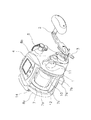
電動リールは、釣り竿に装着可能なリール本体1と、リール本体1の側方に配置されたスプール10の回転用のハンドル2と、ハンドル2のリール本体1側に配置されたドラグ調整用のスタードラグ3と、水深表示用のカウンタケース4と、を主に備えている。
The electric reel includes a
リール本体1は、フレーム7と、フレーム7の左右を覆う第1側カバー8a及び第2側カバー8bと、フレーム7の前部を覆う前カバー9(図2)とを有している。フレーム7は、例えば、ガラス繊維を含浸したポリアミド樹脂等の合成樹脂製であり、第1側板7a及び第2側板7bと、それらを下部、後部及び前上部の3箇所で連結する複数の連結部材7cと、を有している。
The
図2に示すように、リール本体1の内部には、スプール10に連動して動作するレベルワインド機構13(図2)やハンドル2及びモータ12の回転をスプール10に伝達する回転伝達機構等が設けられている。
As shown in FIG. 2, the
また、リール本体1の内部には、モータ12及びハンドル2に連結された糸巻用のスプール10が回転自在に支持されている。スプール10の内部に、スプール10を糸巻取方向に回転駆動するモータ12が配置されている。
Further, a
図1に示すように、第2側カバー8bの中央下部には、ハンドル2が回転自在に支持されている。また、ハンドル2の支持部分の上方前部には、モータ12を複数段階に制御するための調整レバー5が揺動自在に支持されている。調整レバー5は、スプール速度を複数段階のいずれかに設定するスプール速度設定部として機能する。また、調整レバー5は、釣り糸に作用する張力を複数段階のいずれかに設定する張力設定部としても機能する。調整レバー5の後方には、クラッチ操作部材11が揺動自在に配置されている。クラッチ操作部材11は、ハンドル2及びモータ12とスプール10との駆動伝達をオンオフするクラッチ(図示せず)をオンオフ操作するための部材である。このクラッチをオンすると、仕掛けの自重による糸繰り出し中に、糸繰り出し動作を停止できる。ハンドル2と逆側の第1側カバー8aには、電源ケーブル接続用のケーブルコネクタ14が下向きに装着さ
れている。
As shown in FIG. 1, the
前カバー9には、釣り糸通過用の横長の開口9aが形成されている。下部の連結部材7cには、電動リールを釣り竿に装着するための竿装着脚部7dが形成されている。
The
<モータの構成>
モータ12は、例えば、定格出力が180ワット程度のブラシレスモータであり、電動リールに用いるものとしては比較的大容量のものである。
<Configuration of motor>
The
モータ12は、図2に示すように、モータケース15と、モータケース15の内周面に設けられた固定子16と、固定子16の内周側に配置された回転子17と、回転子が固定された出力軸18と、を有している。モータケース15は、耐食性を高めるためにアルマイト処理されたアルミニウム合金製の部材である。モータケース15は、図4に示すように、一端に配置される第1カバー部15aと、他端に配置される第2カバー部15bと、第1カバー部15aと第2カバー部15bとの間に配置される中間カバー部15cと、を有している。第1カバー部15a及び第2カバー部15bは、同じ外径を有する有底筒状の部材であり、筒状部分が対向して配置されている。中間カバー部15cは、第1カバー部15a及び第2カバー部15bと同じ外径を有する筒状の部材である。第1カバー部15a、第2カバー部15b及び中間カバー部15cは、第1カバー部15a側から挿入された第2カバー部15bにねじ込まれる複数本(例えば3本)の固定ボルト29により一体で固定されている。固定ボルト29は、メッキ等の防食被膜により防食処理されている。したがって、中間カバー部15cは、第1カバー部15a及び第2カバー部15bにより挟持されている。第2カバー部15bの筒状部分には、図2及び図4に示すように、水抜き用の少なくとも一つの貫通孔15dが径方向に沿って形成されている。貫通孔15dはモータ12内部に結露等により生じた水をモータ12内部から抜くために設けられている。貫通孔15dは、竿装着脚部7dに向かう下部と、その両側とに、例えば3つ設けられている。
As shown in FIG. 2, the
固定子16は、中間カバー部15cに固定された複数(例えば3個)の積層コア16aと、積層コア16aに巻回された、U相、V相及びW相の3つのコイル16bと、を有している。積層コア16aは、例えば無方向性珪素鋼板製である。積層コア16aには、固定ボルト29により回転方向に位置決めされるU字状に凹んで形成された複数(3個)の位置決め凹部16c(図2)が形成されている。固定子16は、露出部分がメッキ等の防食被膜により防食処理されている。なお、図4では、固定ボルト29が直径上に2本配置されているように描かれているが、これは模式的に表したものであり、実際には、図2に示すように、3本の固定ボルト29が周方向に等間隔に配置されている。
The
回転子17は、S極及びN極を有する2極の磁石17aと、磁石17aを保持する磁石ホルダ17bとを含んでいる。磁石ホルダ17bは、出力軸18に一体回転可能に連結されている。回転子17は、露出部分がメッキ等の防食被膜により防食処理されている。
The
出力軸18は、例えば、ステンレス合金製の軸であり、第1カバー部15a及び第2カバー部15bに左右一対の軸受27により回転自在に支持されている。出力軸18の第1端(図4左端)には、出力軸18の糸繰り出し方向の回転を禁止するためのワンウェイクラッチ28が装着されている。ワンウェイクラッチ28は、リール本体1の第1側板7aに形成された膨出部7e内に外輪28aが回転不能に装着されたローラクラッチである。出力軸18の第2端(図4右端)には、図示しない回転伝達機構を構成する遊星歯車機構の太陽ギアが固定されている。スプール10には遊星歯車機構を介してモータ12の回転が伝達される。遊星歯車機構は、例えば1/50の減速比でモータ12の回転を減速する。
The
モータケース15の第2カバー部15bは、膨出部7eに芯出された状態で連結され、複数(例えば2本)の固定ボルト31により固定されている。これよりモータ12がリール本体1に固定される。第2カバー部15bの端部からは、コイル16bに電気的に接続される3本のモータ線34がカウンタケース4に向けて延びている。
The second cover portion 15b of the
リール本体1の第1側板7a及び第2側板7bの上部に、図1及び図2に示すように、釣り糸の先に装着された仕掛けの水深を表示するカウンタケース4が固定されている。
As shown in FIGS. 1 and 2, a
<カウンタケース構成>
カウンタケース4は、図2及び図3に示すように、リール本体1の前上部に載置されたケース本体19と、液晶ディスプレイを有する水深表示部22と、リール制御部23と、
を備えている。
<Counter case configuration>
As shown in FIGS. 2 and 3, the
It has.
ケース本体19は、リール本体1の第1側板7a及び第2側板7bに固定されている。ケース本体19は、上面部33を有し、外部に露出する合成樹脂製の上ケース部材30と、上ケース部材30に固定される下ケース部材32と、を有している。
The case
上ケース部材30は、例えば、ガラス短繊維で強化されたポリアミド樹脂製である。上ケース部材30は、表示部分が前細りに形成されている。上ケース部材30は、内部に下ケース部材32とで収納空間を有している。
The
上面部33の表示部分には、概ね台形形状の表示用に開口する表示枠33aが形成されている。表示枠33aの開口は、上ケース部材30に溶着された透明カバー37により塞がれている。
In the display portion of the
また、図3に示すように、表示枠33aの後方には、メニュースイッチSW1、決定スイッチSW2、及びメモスイッチSW3が配置されている。メニュースイッチSW1は、例えば、選択操作を行うためのメニュー操作用のスイッチである。決定スイッチSW2は、例えば、メニュースイッチSW1で選択された操作を決定するためのスイッチである。メモスイッチSW3は、例えば、棚メモ用のスイッチである。メニュースイッチSW1は、水深表示部22内の表示項目を選択するために使用されるボタンである。たとえば、メニュースイッチSW1を操作するごとに上からモード(仕掛けの水深を水面からの深さで表示するモード)と底からモード(仕掛けの水深を水底からの水深で表示するモード)とに切り換える。またメニュースイッチSW1を3秒以上長押しすると、長押しの都度、モータ12の制御モードを速度一定モードと張力一定モードとに切り換えできる。
As shown in FIG. 3, a menu switch SW1, a decision switch SW2, and a memo switch SW3 are arranged behind the
ここで、速度一定モードは、調整レバー5の揺動位置に応じてスプール10の回転速度の上限速度を複数段階(例えば31段階)に多段速度制御可能なモードである。張力一定モードは、調整レバー5の揺動位置に応じて釣り糸に作用する張力の上限張力を複数段階(例えば31段階)に多段張力制御可能なモードである。なお、両モードとも、最高段階の31段階は、100%デューティでモータ12を動作させる速巻速度であり、電流制限は行うが、速度制御は行わない。なお、速度一定モードにおいて、第1段階のスプール回転速度は、28rpm(rpm=1分間の回転数)から30rpmの範囲に制御される。したがって、モータ12の回転速度は、1400rpmから1500rpmの範囲に制御される。
Here, the constant speed mode is a mode in which the upper limit speed of the rotational speed of the
下ケース部材32は、例えば、アルミニウム合金及びマグネシウム合金等の軽量で熱伝導率が高い金属製の枠状の部材である。下ケース部材32は、複数本(例えば4本)の固定ねじ(図示せず)により上ケース部材30を固定している。水深表示部22及びリール制御部23用の2枚の回路基板20が下ケース部材32に搭載されている。
The
下側の回路基板20下面には、モータ12駆動用の複数のFET(電界効果トランジスタ)25を含むモータ駆動回路70が搭載されている。FET25は、モータ12をPWM(パル幅変調)する際にデューティ比に応じてスイッチングするスイッチ素子として機能する。また、FET25は、例えば、モータ12の固定子16のコイル16bを順に励磁及び消磁するためのスイッチ素子として機能する。また、下側の回路基板20に、コンデンサ21が接続されている。コンデンサ21は、FET25から発生するノイズを平滑化する機能を有している。また、モータ12の逆起電流を整流する機能を有している。この逆起電流を整流することにより、モータ12の回転位相を検出している。この検出された回転位相によりFET25が制御されてコイル16bを順に励磁及び消磁し、モータ12を回転させる。また、この回転位相によりモータ12の回転速度を検出している。
A
図3に示すように、水深表示部22は、中央に配置された4桁の16セグメント表示の水深表示領域22aと、その右下方に配置された3桁の7セグメントのメモ水深表示領域22bと、メモ水深表示領域22bの左方に配置された7セグメントの段階表示領域22cとを有している。段階表示領域22cは、調整レバー5の位置(段階SC)を、例えば0から30までの31段階で表示する。ここでは、水深表示領域22aに16セグメントの表示を用いているので、水深表示がより視認しやすくなる。
As shown in FIG. 3, the water
<リール制御部の構成>
リール制御部23は、図5に示すように、機能構成としてモータ12を制御するモータ制御部60(モータ制御装置の一例)と、水深表示部22を制御する表示制御部61と、を有している。モータ制御部60は、モータ12をPWM制御するとともに、モータ12の固定子16の複数のコイル16bを励磁及び消磁する制御を行う。この励磁及び消磁制御の際には、モータ制御部60は、コンデンサ21でモータ12の逆起電流を整流して得られたデータによりモータ12の回転位相を検出し、検出された回転位相に応じて複数のコイル16bを順次励磁及び消磁する。
<Configuration of reel control unit>
As shown in FIG. 5, the
リール制御部23には、調整レバー5、メニュースイッチSW1、決定スイッチSW2、及びメモスイッチSW3が接続されている。また、スプール10の回転速度及び回転方向を検出するためのスプールセンサ41と、コイル16bへの通電をオンオフするとともにモータ12をPWM駆動する5つのFET25及びコンデンサ21を含むモータ駆動回路70と、ブザー47と、水深表示部22と、記憶部46と、他の入出力部と、が接続されている。モータ駆動回路70には、モータ12に流れる電流値を検出する電流検出部70aが設けられている。電流検出部70aは、モータに流れる電流値に加えて電流方向も検出可能である。
The
スプールセンサ41は、前後に並べて配置された2つのリードスイッチから構成されており、いずれのリードスイッチが先に検出パルスを発したかによりスプール10の回転方向を検出できる。また、検出パルスによりスプールの回転数及び回転速度を検出できる。
The
記憶部46はたとえばEEPROM等の不揮発メモリから構成されている。記憶部46には、図6に示すように、棚位置等の表示データを記憶する表示データ記憶エリア50と、実際の糸長とスプール回転数との関係を示す糸長データを記憶する糸長データ記憶エリア51と、段階SCに応じたスプール10の巻き上げ速度(rpm)及び巻き上げトルク(電流値)を記憶する回転データ記憶エリア52と、種々のデータを記憶するデータ記憶エリア53とが設けられている。
The
回転データ記憶エリア52には、速度一定モードでの段階SC毎の上限速度Vsc、上限速度Vscの下限値Vsc1及び上限値Vsc2のデータと、張力一定モードでの段階SC毎の上限張力Qsの下限値Qsc1及び上限値Qsc2のデータと、が記憶されている。データ記憶エリア53には糸長に関する各種のデータが格納されている。たとえば船縁停止位置が格納されている。
In the rotation
モータ制御部60は、ソフトウェアで実現される機能構成として、回転位相検出部62と、モータ電流制御部63と、回転方向判断部64と、起動制御部65と、回転制御部66と、スプール速度検出部67と、スプール速度制御部68と、モード切換部69と、を有している。回転位相検出部62は、モータ12の逆起電流を整流して得られたデータによりモータ12の回転位相を検出する。この回転位相の時間的な経過によりモータ12の回転速度も検出可能である。
The
モータ電流制御部63は、調整レバー5の揺動操作位置に応じて、モータ12に流れる電流値を複数段階(例えば31段階)に制御する。すなわち、張力一定モードの際にモータ12の制御を行う。
The motor
回転方向判断部64は、起動制御部65による制御時に所定のパターンでモータ12に電流を流すときにモータ12の回転方向を判断する。モータ駆動回路70内の電流検出部70aにより検出された電流値及び電流方向により、モータ12が糸巻取方向に回転したか否かを判断する。前述したように、モータ12の出力軸18は、ワンウェイクラッチ28により糸繰り出し方向の回転が禁止されている。このため、モータ12が糸繰り出し方向に回転すると、モータ12に流れる電流が増加する。この電流値の増加によりモータが糸繰り出し方向に回転していることを検出する。
The rotation
起動制御部65は、パターン通流部65aを有している。パターン通流部65aは、モータ12が所定回転速度未満で回転して逆起電流による回転位相の検出ができないときに、図8に示す、第1パターンから第6パターンを有する所定のパターンで電流を順次U相のコイル16bからW相のコイル16bに1000rpmで回転するような電流を所定時間(例えば0.5秒間)流す。そして、その都度回転方向を検出し、回転子17が糸巻取方向に回転したときに起動制御を終了する。
The
図8に示す所定のパターンは、第1パターンから第6パターンの6つのパターンで構成されている。各パターンでは、回転子17が図8に示した位置にあると、モータ12は、糸巻取方向に回転する。第1パターンは、矢印Aで示すようにU相からV相のコイル16bに電流を流す。このとき、前述したように、図8に示す位置以外に回転子17が位置していると、回転子17は、回らないか糸繰り出し方向に回転する。回転子17が糸巻取方向に回転していないことを回転方向判断部64により判断した場合は、第2パターンで電流を流す。第2パターンは、矢印Bで示すようにU相からW相のコイル16bに電流を流す。同様に、回転子17が糸巻取方向に回転していない場合は、矢印Cで流す第3パターン、矢印Dで流す第4パターン、矢印Eで流す第5パターン、矢印Fで流す第6パターンで、回転子17が糸巻取方向に回転するまでU相からV相のコイル16bに電流を流す。なお、第3パターンは、V相コイルからW相コイルへ電流を流す。第4パターンは、V相コイルからU相コイルへ電流を流す。第5パターンは、W相コイルからU相コイルへ電流を流す。第6パターンは、W相コイルからV相コイルへ電流を流す。この第6パターンまで第1パターンから順に電流を流せば、それまでのいずれかのパターンで、回転子17がどのような位相にあっても回転子17は糸巻取方向に回転する。したがって、回転子17が糸巻取方向に回転するまでは、回転方向を判断しながら次のパターンの電流を流す。そして、回転子17が糸巻取方向に回転したことを判断すると、処理を終了する。
The predetermined pattern shown in FIG. 8 includes six patterns from a first pattern to a sixth pattern. In each pattern, when the
回転制御部66は、モータ12が回転してFET25のオンオフ時に発生する逆起電流によって回転位相を検出できる場合、検出されたモータ12の回転子17の回転位相に応じて、3つのコイル16bに電流を流す。発生する逆起電流を整流した回転位相の検出信号の一例を図7に示す。図7では、U相からW相まで順に図8に示すように電流を流したときに発生する検出信号を示している。図8は、起動制御部65による制御の際に使用する所定のパターンを図示している。所定のパターンは、回転子17がいずれの回転位相にあっても、3相2極のモータ12の場合、6つのパターンのいずれかのパターンのときに回転子17が糸巻取方向に回転できる。
When the
回転制御時には、回転位相の検出結果に応じた所定のパターンで電流を流している。また、U相、V相、W相での各コイル16bのプラス側は、スプール速度又は電流値に応じた周期でオンオフしている。一方、各コイル16bのマイナス側は、例えば20kHzの周期のPWM制御により、設定されたスプール速度又は電流値に応じてデューティ制御している。
At the time of rotation control, a current is passed in a predetermined pattern according to the detection result of the rotation phase. Further, the plus side of each
スプール速度検出部67は、スプールセンサ41からの出力により、モータ制御部60において使用するスプール10の速度及びスプール10の回転方向を検出する。
The spool
スプール速度制御部68は、スプール速度設定部としての調整レバー5の揺動操作位置に応じて、スプール10の回転速度を複数段階(例えば31段階)に制御する。すなわち、速度一定モードの際にモータ12を制御する。
The spool
モード切換部69は、張力一定モードと速度一定モードとを切り換えるものである。前述したように、例えば、メニュースイッチSW1の3秒以上長押し操作により動作モードの切り換え動作が実現される。
The
このような構成の電動リールでは、釣り糸を繰り出す時には、クラッチ操作部材11を手前(後方)に操作することによりクラッチをオフする。クラッチオフすると、スプール10が自由回転状態になり、釣り糸に装着された重りの自重により釣り糸がスプール10から繰り出される。釣り糸が繰り出されるとスプール10が糸繰り出し方向に回転し、スプールセンサ41の検出パルスにより水深表示部22の水深表示が繰り出し量に応じて変化する。仕掛けが棚に到達すると、ハンドル2を糸巻取方向に回して図示しないクラッチ戻し機構によりクラッチをオンして釣り糸の繰り出しを停止する。
In the electric reel having such a configuration, when the fishing line is fed out, the clutch is turned off by operating the clutch operation member 11 forward (rear). When the clutch is turned off, the
魚の当たりがあると、調整レバー5を操作し釣り糸を巻き上げる。調整レバー5を図1時計回りに揺動させると、その揺動角度に応じてスプール10の回転速度又は釣り糸に作用する張力の最大値を段階的に設定できる。
When the fish hits, the
<リール制御部の動作>
次にリール制御部23の具体的な制御動作について、図9以降に示す制御フローチャートに基づいて説明する。なお、以下の説明は本発明の制御手順の一例であり、本発明の制御手順は以下のフローチャートで示した内容に限定されない。
<Operation of reel control unit>
Next, a specific control operation of the
電動リールに図示しない電源ケーブルを介して電源が投入されると、図9のステップS1において初期設定を行う。この初期設定では各種の変数やフラグをリセットしたりする。また、船縁停止位置FN(停止水深の一例)を標準的な船縁停止位置である第1糸長L1(たとえば、6m)にセットする。 When power is supplied to the electric reel via a power cable (not shown), initialization is performed in step S1 of FIG. In this initial setting, various variables and flags are reset. Further, the ship edge stop position FN (an example of the stop water depth) is set to a first yarn length L1 (for example, 6 m) which is a standard ship edge stop position.
次にステップS2では表示処理を行う。表示処理では、水深表示等の各種の表示処理を行う。ここで、段階表示領域22cに段階SCを表示する。
Next, in step S2, display processing is performed. In the display process, various display processes such as water depth display are performed. Here, the stage SC is displayed in the
ステップS3では、後述する各動作モードで算出される水深LXが第1糸長L1以下か否かを判断する。ステップS4では、いずれかのスイッチSW1〜スイッチSW3又は調整レバー5が押されたか否かのスイッチ入力の判断を行う。またステップS5ではスプール10が回転しているか否かを判断する。この判断は、スプールセンサ41の出力により判断する。ステップS6では、その他の指令や入力がなされたか否かを判断する。
In step S3, it is determined whether or not the water depth LX calculated in each operation mode described later is equal to or less than the first yarn length L1. In step S4, it is determined whether or not any of the switches SW1 to SW3 or the
水深LXが第1糸長L1以下のときには、ステップS3からステップS7に移行する。ステップS7では、その水深で5秒以上停止しているか否かを判断する。6m以下の水深で5秒以上停止しているのは、船縁で釣った魚を取り込んだり、仕掛けに餌を付け直したりする等の動作を行っているときが多い。このため、5秒以上停止していると判断するとステップS8に移行し、そのときの水深LXを船縁停止位置FNにセットする。5秒未満の時はステップS7からステップS4に移行する。 When the water depth LX is equal to or less than the first yarn length L1, the process proceeds from step S3 to step S7. In step S7, it is determined whether or not the water has been stopped for 5 seconds or more at the water depth. The reason for stopping for more than 5 seconds at a water depth of 6 m or less is often when the fish caught on the ship's edge is taken in or the bait is reattached to the device. For this reason, if it is determined that the vehicle has stopped for 5 seconds or more, the process proceeds to step S8, and the water depth LX at that time is set to the ship edge stop position FN. When it is less than 5 seconds, the process proceeds from step S7 to step S4.
スイッチ入力がなされた場合にはステップS4からステップS9に移行して図10に示すスイッチ入力の処理を実行する。またスプール10の回転が検出された場合にはステップS5からステップS10に移行する。ステップS10では各動作モード処理を実行する。その他の指令あるいは入力がなされた場合にはステップS6からステップS11に移行してその他の処理を実行する。
When a switch input is made, the process proceeds from step S4 to step S9, and the switch input process shown in FIG. 10 is executed. If rotation of the
ステップS9のスイッチ入力処理では、図10のステップS15で調整レバー5が操作されたか否かを判断する。ステップS16では、メニュースイッチSW1が3秒以上長押されたか否かを判断する。ステップS17では、その他のスイッチが操作されたか否かを判断する。その他のスイッチの操作にはメニュースイッチSW1の通常操作、決定スイッチSW2、及びメモスイッチSW3等の操作を含んでいる。
In the switch input process of step S9 , it is determined whether or not the
調整レバー5が揺動操作されたと判断するとステップS15からステップS18に移行する。ステップS18では、調整レバー5の段階SCを取り込む。調整レバー5には図示しないロータリエンコーダが設けられており、ロータリエンコーダの出力を取り込む。ステップS19では、調整レバー5が段階SC=0に操作されたか否かを判断する。段階SCが「0」の場合は、ステップS20に移行し、モータ12をオフし、ステップS16に移行する。段階SCが「0」ではない場合は、ステップS21に移行する。
If it is determined that the
ステップS21では、図11に示すモータ回転制御処理を行い、ステップS22に移行する。ステップS22では、メニュースイッチSW1の長押し操作により速度一定モードか張力一定モードのいずれか設定されたか否かを判断する。速度一定モードが設定されている場合は、ステップS22からステップS23に移行する。ステップS23では速度一定モードを実現するためのスプール速度制御処理を行い、ステップS16に移行する。このスプール速度制御処理では、段階SC毎に設定された目標スプール回転速度となるようにモータ12をフィードバック制御する。
In step S21, the motor rotation control process shown in FIG. 11 is performed, and the process proceeds to step S22. In step S22, it is determined whether the constant speed mode or the constant tension mode has been set by a long press operation of the menu switch SW1. When the constant speed mode is set, the process proceeds from step S22 to step S23. In step S23, a spool speed control process for realizing the constant speed mode is performed, and the process proceeds to step S16. In this spool speed control process, the
メニュースイッチSW1が長押し操作されると、ステップS16からステップS25に移行する。ステップS25では、速度一定モードが設定されているか否かを判断する。速度一定モードが設定されている場合は、ステップS25からステップS26に移行して張力一定モードに設定し、ステップS17に移行する。張力一定モードが設定されている場合は、ステップS25からステップS27に移行して速度一定モードに設定し、ステップ
S17に移行する。
張力一定モードが設定されている場合は、ステップS22からステップS24に移行する。ステップS24では、張力一定モードを実現するモータ電流制御処理を行いステップS16に移行する。モータ電流制御処理では、段階SC毎に設定された目標電流値となるようにモータ12をフィードバック制御する。
When the menu switch SW1 is pressed and held, the process proceeds from step S16 to step S25. In step S25, it is determined whether the constant speed mode is set. If the constant speed mode is set, the process proceeds from step S25 to step S26, the constant tension mode is set, and the process proceeds to step S17. If the tension constant mode has been set, it sets the constant speed mode shifts from step S25 to step S27, to migrate to the step S17.
When the constant tension mode is set, the process proceeds from step S22 to step S24. In step S24, a motor current control process for realizing the constant tension mode is performed, and the process proceeds to step S16. In the motor current control process, the
他のスイッチ入力がなされると、ステップS17からステップS28に移行し、たとえば、底からモードへの変更やその他のモードの設定等の他のスイッチ入力処理を行い、図9に示すメインルーチンに戻る。
If other switch inputs are made, the process proceeds from step S17 to step
ステップS21のモータ回転制御処理では、図11のステップS31でモータ12がすでに起動しているか否かを判断する。モータ12が起動している場合はステップS40に移行する。モータ12が起動していない場合はステップS32に移行する。ステップS32では、第1パターンから順に電流をコイル16bに流すための変数N(Nは正の整数)を「1」にセットする。ステップS33では、1000rpmの回転速度でモータ12を回転可能な第Nパターンの電流をコイル16bに流す。ステップS34では、モータ12の回転方向が糸巻取方向か否かを判断する。糸巻取方向の回転の場合は、ステップS34からステップS40に移行する。
In the motor rotation control process in step S21, it is determined whether or not the
モータ12が糸巻取方向に回転していない場合は、ステップS34からステップS35に移行する。ステップS35では、次のパターンの電流を流すために変数Nを1インクリメントする。ステップS36では、変数Nが「7」か否かを判断する。変数Nが「7」の場合はステップS37に移行して変数Nを「1」にセットして、ステップS38に移行する。ステップS38では、パターンの出力が0.5秒を超えたか否かを判断する。パターンを出力してから0.5秒を超えるとステップS40に移行する。また、変数Nが7ではない場合は、ステップS36からステップS33に移行し、次のパターンを出力する。これを、モータ12が糸巻取方向に回転するまで繰り返す。
When the
モータ12が糸巻取方向に回転するとステップS34からステップS40に移行する。ステップS40では、モータ12の回転速度V及び現在のデューティDRを取り込む。これらは記憶部46に記憶されている。ステップS41では、モータ12の回転速度が4000rpm以下か否かを判断する。モータ12の回転が4000rpm以下の場合は、ステップS41からステップS43に移行する。ステップS43では、低速制御処理を行う。具体的には、逆起電流により得られる図7に示す回転位相を示す信号を取り込み、回転位相を割り出して進角制御することなく励磁位置を決定する。しかし、この制御で高速回転を行うと、効率が悪くなり、消費電力が著しく大きくなる。そこで、ステップS41でモータ12が4000rpmを超えて回転していると判断すると、ステップS42に移行する。ステップS42では、モータ12が5000rpm以上で回転しているか否かを判断する。5000rpm以上でモータ12が回転していると判断すると、ステップS42からステップS44に移行し高速処理を行う。この高速処理では、回転位相の信号の割り込み信号での位置検出と進角制御とを入れて励磁する。ここで、ステップS41とステップS42とでの判断に1000rpmのヒステリシスを設けているのは、同じ回転速度で判断することにより発生するチャタリングを防止するためである。
When the
具体的には、現在の速度で計算されている励磁位置を割り込み信号で同期させる。例えば、W相の回転位相の信号から回転速度を割り出し、100μ秒の間隔で回転速度を求める。そして、下記の3つの条件で各角度を再設定を行い回転角を調整する。 Specifically, the excitation position calculated at the current speed is synchronized with an interrupt signal. For example, the rotational speed is determined from the W phase rotational phase signal, and the rotational speed is obtained at intervals of 100 μs. Then, each angle is reset under the following three conditions to adjust the rotation angle.
1.第1及び第6パターンでU相の位置検出割り込みが発生した場合、位置(角度)を0度とする。 1. When a U-phase position detection interrupt occurs in the first and sixth patterns, the position (angle) is set to 0 degrees.
2.第2及び第3パターンでV相の位置検出割り込みが発生した場合、位置(角度)を120度とする。 2. When a V-phase position detection interrupt occurs in the second and third patterns, the position (angle) is set to 120 degrees.
3.第4及び第5パターンでU相の位置検出割り込みが発生した場合、位置(角度)を240度とする。 3. When a U-phase position detection interrupt occurs in the fourth and fifth patterns, the position (angle) is set to 240 degrees.
ここで、ノイズ等による不要な角度での割り込みを防ぐために、現在の励磁位置により次にくる位相の回転位相の信号に絞って検出を行う。具体的には、第2パターンの場合は、V相の検出を行い、第4パターンの場合は、W相の検出を行い、第6パターンの場合は、U相の検出を行う。上記の動作をモータ12が1回転する毎に行い。進角を調整しながらモータ12を回転させている。これらの処理が終わると、ステップS22に移行する。
Here, in order to prevent interruption at an unnecessary angle due to noise or the like, detection is performed by narrowing down to the next rotation phase signal at the current excitation position. Specifically, in the case of the second pattern, the V phase is detected, in the case of the fourth pattern, the W phase is detected, and in the case of the sixth pattern, the U phase is detected. The above operation is performed every time the
ステップS10の各動作モード処理では、図12のステップS51でスプール10の回転方向が糸繰り出し方向か否かを判断する。この判断は、スプールセンサ41のいずれのリードスイッチが先にパルスを発したか否かにより判断する。スプール10の回転方向が糸繰り出し方向と判断するとステップS51からステップS52に移行する。ステップS52では、スプール回転数が減少する毎にスプール回転数から糸長データ記憶エリア51に記憶されたデータを読み出して水深(放出された糸長)LXを算出する。この水深LXがステップS2の表示処理で表示される。ステップS53では、得られた水深LXが棚又は底位置に一致したか、つまり、仕掛けが棚又は底に到達したか否かを判断する。棚又は底位置は、仕掛けが棚又は底に到達したときにメモスイッチSW3を押すことで記憶部46の表示データ記憶エリア50にセットされる。ステップS54では、学習モード等の他のモードか否かを判断する。
In each operation mode process in step S10, it is determined in step S51 in FIG. 12 whether or not the rotation direction of the
水深が棚位置又は底位置に一致するとステップS53からステップS55に移行し、仕掛けが棚又は底に到達したことを報知するためにブザー47を鳴らす。他のモードの場合には、ステップS54からステップS56に移行し、指定された他のモードを実行する。他のモードではない場合には、各動作モード処理を終わりメインルーチンに戻る。
When the water depth matches the shelf position or the bottom position, the process proceeds from step S53 to step S55, and the
スプール10の回転が糸巻き取り方向と判断するとステップS51からステップS57に移行する。ステップS57では、スプール回転数から糸長データ記憶エリア51に記憶されたデータを読み出して水深LXを算出する。この水深LXがステップS2の表示処理で表示される。
When the rotation of the
ステップS58では、船縁停止位置に到達したか否かを判断する。船縁停止位置FNに到達するとステップS58からステップS59に移行する。ステップS59では、仕掛けが船縁にあることを報知するためにブザー47を鳴らす。ステップS60では、モータ12をオフする。これにより魚や釣れたときや仕掛けを回収して餌を交換するときに、取り込みやすい位置に魚や仕掛けが配置される。船縁停止位置まで巻き取っていない場合にはメインルーチンに戻る。
In step S58, it is determined whether the ship edge stop position has been reached. When the ship edge stop position FN is reached, the process proceeds from step S58 to step S59. In step S59, the
<特徴>
(A)モータ制御部60は、2極の磁石17aを有する回転子17とUVWの3相のコイル16bを有する固定子16とを有し、逆起電流により回転子17の回転位相を検出可能であり、ワンウェイクラッチ28により糸繰り出し方向の回転が禁止されるブラシレスモータを用いたモータ12により、スプール10を糸巻取方向に回転させる。モータ制御部60は、回転方向判断部64と、回転位相検出部62と、起動制御部65と、回転制御部66と、を備えている。回転方向判断部64は、回転子17の回転方向を検出する。回転位相検出部62は、逆起電流により回転子の回転位相及び回転速度を検出する。起動制御部65は逆起電流により回転位相を検出できないとき、3相のコイルに回転子17の回転位相に応じた複数のパターンで所定の順に、回転方向判断部64が複数のパターンのいずれかで回転子17が糸巻取方向に回転したと判断するまで電流を流してモータ12を起動する。回転制御部66は、回転位相が検出可能になると、逆起電流により検出した回転位相に応じて3相のコイル16bのいずれかに電流を流してモータ12を制御する。
<Features>
(A) The
このモータ制御部60では、回転位相検出部62が回転子17の回転位相を検出できない起動時に、起動制御部65によりブラシレスモータ12が起動される。起動制御部65では、回転子17の回転位相を検出できないため、回転子17の回転位相に応じた複数のパターンで電流を順に間欠的に回転方向判断部64が糸巻取方向に回転子17が回転したと判断するまで3相のコイル16bに流す。そこれにより、回転子17の回転位相を、センサを用いて検出することなく、回転子17を糸巻取方向に回転できる。このため、逆起電流により回転子17の回転位相を検出できるようになると、回転制御部66による制御に切り換わる。回転制御部66では、回転子17の回転位相を逆起電流により検出し、回転位相に応じて3相のコイル16bのいずれかに電流を流す。
In the
ここでは、例えば負荷の変動により回転速度が大きく変化する電動リールに使用されるブラシレスモータを用いたモータ12を、逆起電流により回転位相を検出できるときと回転位相を検出できないときとで異なる制御を行っている。このため、センサレスのブラシレスのモータ12により電動リールを駆動しても、速度の増減に対応でき、かつコストを削減できるようになる。
Here, for example, the
(B)モータ制御部60において、複数のパターンは、第1パターンから第6パターンの6つのパターンを有している。第1パターンは、U相コイルからV相コイルへ電流を流すパターンである。第2パターンは、U相コイルからW相コイルへ電流を流すパターンである。第3パターンは、V相コイルからW相コイルへ電流を流すパターンである。第4パターンは、V相コイルからU相コイルへ電流を流すパターンである。第5パターンは、W相コイルからU相コイルへ電流を流すパターンである。第6パターンは、W相コイルからV相コイルへ電流を流すパターンである。
(B) In the
起動制御部は65、第1パターンから第6パターンの順に3相のコイル16bに、回転子17が糸巻取方向に回転したことを回転方向判断部64が判断するまで電流を所定時間流すパターン通流部65aを有する。
The
この場合には、UVWの3相のコイル16bに第1パターンから第6パターンの順に電流を流せば、S極がU相のコイル16bに対向した状態では、回転子17が糸巻取方向に回わる。したがって、回転子17の回転位相がいずれにあっても、いずれかのパターンで必ず回転子17が糸巻取方向に回転する。このため、回転方向判断部64により糸巻取方向への回転が確認されると、位置センサを用いることなく回転子17を糸巻取方向に回転させることができる。
In this case, if current is passed through the UVW three-
(C)モータ制御部60において、固定子16に流れる電流の電流値及び電流の通流方向を検出する電流検出部70aをさらに備える。回転方向判断部64は、電流検出部70aにより検出された電流値及び電流方向によりモータ12が糸巻取方向に回転したか否かを判断する。この場合には、ワンウェイクラッチ28により回転子17の糸繰り出し方向の回転が禁止されたモータ12の固定子16に、糸繰り出し方向に回転子17を回転させる電流が流れると、回転子17が回転できないため電流値が高くなる。したがって、電流値及びその電流方向により回転子17の糸巻取方向の回転を精度良く判断でき、回転子17の回転位相にかかわらず回転子17を糸巻取方向に確実に回転させることができる。
(C) The
(D)モータ制御部60において、回転位相によりモータ12の回転速度を検出するモータ速度検出部をさらに備え、回転制御部66は、回転速度が第1速度以下の時、回転位相検出部62により検出した回転位相に応じて第1パターンから第6パターンのいずれかで3相のコイルに電流を通流し、回転速度が第1速度より速い第2速度以上のとき、回転位相検出部62からの割り込み信号と進角制御とにより3相のコイルに電流を通流する。
(D) The
この場合には、例えば、ブラシレスモータが第1速度として例えば4000rpm以下で回転しているときは、検出された回転位相を読み込んで進角制御することなく励磁するコイルを決定して電流を流す。また、第2速度として例えば5000rpm以上でブラシレスモータが回転しているときは、回転位相検出部62からの割り込み信号と進角制御とにより、現在の励磁位置の次にくる1相の割り込み信号によりコイル16bで電流を流す。これにより、ブラシレスモータ12の回転速度が遅いときは、高精度の回転制御を行え、速度が高いときは、効率を高めて電力消費を抑えることができる。
In this case, for example, when the brushless motor is rotating at a first speed of, for example, 4000 rpm or less, the detected rotation phase is read and a coil to be excited is determined without controlling the advance angle, and a current is supplied. Further, when the brushless motor is rotating at, for example, 5000 rpm or more as the second speed, the interrupt signal from the
(E)モータ制御部60において、調整レバー5と、スプール速度検出部67をさらに備える。調整レバー5は、スプール10の回転速度を複数段階のいずれかに設定する。スプール速度検出部67は、スプール10の回転速度を検出する。回転制御部66は、スプール速度検出部67の検出結果を参照して調整レバー5で設定されたスプール回転速度となるようにモータ12を制御する。
(E) The
この場合には、スプール速度を複数段で一定に制御できるとともに、負荷によりスプール速度が低下し、モータ12の回転が遅くなり回転子17の回転位相を検出できなくなっても、回転制御部66により高トルクでモータを回転させることができる。
In this case, the spool speed can be controlled to be constant in a plurality of stages, and even if the spool speed decreases due to the load and the rotation of the
<他の実施形態>
以上、本発明の一実施形態について説明したが、本発明は上記実施形態に限定されるものではなく、発明の要旨を逸脱しない範囲で種々の変更が可能である。
<Other embodiments>
As mentioned above, although one Embodiment of this invention was described, this invention is not limited to the said embodiment, A various change is possible in the range which does not deviate from the summary of invention.
(a)前記実施形態では、張力一定モードと、速度一定モードとを切り換え可能にしたが、本発明はこれに限定されない。例えば、速度一定制御だけを行ってもよい。 (A) Although the constant tension mode and the constant speed mode can be switched in the embodiment, the present invention is not limited to this. For example, only constant speed control may be performed.
(b)前記実施形態では、モータ12をスプールの内部に収納したが、モータをスプール外に装着した電動リールにも本発明を適用できる。
(B) In the above embodiment, the
(c)前記実施形態では、モータ操作部材として調整レバーを例示したが本発明はこれに限定されない。例えば、押しボタンの押圧操作時間等により段階を増加及び減少してもよい。 (C) In the above embodiment, the adjustment lever is exemplified as the motor operation member, but the present invention is not limited to this. For example, the number of steps may be increased or decreased depending on the pressing operation time of the push button.
5 調整レバー(スプール速度設定部の一例)
10 スプール
12 モータ
16 固定子
16b コイル
17 回転子
17a 磁石
23 リール制御部
28 ワンウェイクラッチ
60 モータ制御部(電動リールのモータ制御装置の一例)
62 回転位相検出部
64 回転方向判断部
65 起動制御部
66 回転制御部
65a パターン通流部
67 スプール速度検出部
68 スプール速度制御部
70a 電流検出部
5 Adjustment lever (example of spool speed setting section)
DESCRIPTION OF
62 Rotation
65a
Claims (3)
前記固定子に流れる電流の電流値及び前記電流の通流方向を検出する電流検出部と、
前記電流検出部により検出された電流値及び電流方向により前記回転子の回転方向を判断する回転方向判断部と、
前記逆起電流により前記回転子の回転位相を検出する回転位相検出部と、
前記回転位相により前記モータの回転速度を検出するモータ速度検出部と、
前記回転位相検出部が前記逆起電流により前記回転位相を検出できないとき、前記3相のコイルに、前記回転子の回転位相に応じた複数のパターンで所定の順に、回転方向判断部が複数のパターンのいずれかで回転子が糸巻取方向に回転したと判断するまで電流を流してモータを起動する起動制御部と、
前記回転位相を検出できたとき、前記逆起電流により検出した前記回転位相に応じて前記3相のコイルのいずれかに電流を流す回転制御部と、
を備え、
前記複数のパターンは、U相コイルからV相コイルへ電流を流す第1パターンと、U相コイルからW相コイルへ電流を流す第2パターンと、V相コイルからW相コイルへ電流を流す第3パターンと、V相コイルからU相コイルへ電流を流す第4パターンと、W相コイルからU相コイルへ電流を流す第5パターンと、W相コイルからV相コイルへ電流を流す第6パターンと、を有し、
前記回転制御部は、
前記回転速度が第1速度以下のとき及び増速時において前記第1速度より速い第2速度になるまでは、前記回転位相検出部により検出した回転位相に応じて前記第1パターンから前記第6パターンのいずれかで前記3相のコイルに電流を通流し、
前記回転速度が前記第2速度以上のとき及び減速時に前記第1速度になるまでは、回転位相検出部からの割り込み信号と進角制御とにより前記3相のコイルに電流を通流する
電動リールのモータ制御装置。 It has a rotor with a two-pole magnet and a stator with a UVW three-phase coil, and can detect the rotation phase of the rotor by back electromotive current. A motor control device for an electric reel that rotates a spool in a yarn winding direction by a brushless motor,
A current detection unit for detecting a current value of the current flowing through the stator and a current flowing direction of the current;
A rotation direction determination unit that determines a rotation direction of the rotor based on a current value and a current direction detected by the current detection unit ;
A rotational phase detector that detects a rotational phase of the rotor by the counter electromotive current;
A motor speed detector for detecting the rotational speed of the motor based on the rotational phase;
When the rotational phase detection unit cannot detect the rotational phase by the counter electromotive current, the rotational phase determination unit includes a plurality of rotational direction determination units in a predetermined order in a plurality of patterns corresponding to the rotational phase of the rotor. An activation control unit that activates the motor by supplying current until it is determined that the rotor has rotated in the yarn winding direction in any of the patterns;
A rotation control unit for supplying a current to one of the three-phase coils according to the rotation phase detected by the counter electromotive current when the rotation phase is detected;
Equipped with a,
The plurality of patterns include a first pattern for flowing current from the U-phase coil to the V-phase coil, a second pattern for flowing current from the U-phase coil to the W-phase coil, and a second pattern for flowing current from the V-phase coil to the W-phase coil. 3 patterns, a fourth pattern for flowing current from the V-phase coil to the U-phase coil, a fifth pattern for flowing current from the W-phase coil to the U-phase coil, and a sixth pattern for flowing current from the W-phase coil to the V-phase coil And having
The rotation control unit
From the first pattern to the sixth pattern according to the rotational phase detected by the rotational phase detector, when the rotational speed is equal to or lower than the first speed and until the second speed is higher than the first speed at the time of acceleration. Current is passed through the three-phase coil in one of the patterns,
When the rotational speed is equal to or higher than the second speed and until the first speed is reached during deceleration, a current is passed through the three-phase coil by an interrupt signal from the rotational phase detection unit and advance angle control. /> Motor control device for electric reel.
前記スプールの回転速度を検出するスプール速度検出部と、
をさらに備え、
前記回転制御部は、前記スプール速度検出部の検出結果を参照して前記スプール速度設定部で設定されたスプール回転速度となるように前記ブラシレスモータを制御する、
請求項1又は2に記載の電動リールのモータ制御装置。 A spool speed setting unit for setting the rotation speed of the spool in any one of a plurality of stages;
A spool speed detector for detecting the rotation speed of the spool;
Further comprising
The rotation control unit controls the brushless motor so that the spool rotation speed set by the spool speed setting unit is set with reference to a detection result of the spool speed detection unit.
The motor control apparatus of the electric reel of Claim 1 or 2 .
Priority Applications (4)
| Application Number | Priority Date | Filing Date | Title |
|---|---|---|---|
| JP2010266259A JP5763909B2 (en) | 2010-11-30 | 2010-11-30 | Electric reel motor control device |
| TW100129200A TWI523402B (en) | 2010-11-30 | 2011-08-16 | Motor reducer motor control device |
| CN201110290852.5A CN102475076B (en) | 2010-11-30 | 2011-09-20 | The controller for motor of electric fishing reel |
| KR1020110107817A KR101649174B1 (en) | 2010-11-30 | 2011-10-21 | Motor Control Device for Electric Motor Drive Reel |
Applications Claiming Priority (1)
| Application Number | Priority Date | Filing Date | Title |
|---|---|---|---|
| JP2010266259A JP5763909B2 (en) | 2010-11-30 | 2010-11-30 | Electric reel motor control device |
Publications (3)
| Publication Number | Publication Date |
|---|---|
| JP2012115177A JP2012115177A (en) | 2012-06-21 |
| JP2012115177A5 JP2012115177A5 (en) | 2013-11-21 |
| JP5763909B2 true JP5763909B2 (en) | 2015-08-12 |
Family
ID=46087944
Family Applications (1)
| Application Number | Title | Priority Date | Filing Date |
|---|---|---|---|
| JP2010266259A Active JP5763909B2 (en) | 2010-11-30 | 2010-11-30 | Electric reel motor control device |
Country Status (4)
| Country | Link |
|---|---|
| JP (1) | JP5763909B2 (en) |
| KR (1) | KR101649174B1 (en) |
| CN (1) | CN102475076B (en) |
| TW (1) | TWI523402B (en) |
Families Citing this family (5)
| Publication number | Priority date | Publication date | Assignee | Title |
|---|---|---|---|---|
| JP6153714B2 (en) * | 2012-11-19 | 2017-06-28 | 株式会社シマノ | Electric reel |
| JP6166063B2 (en) * | 2013-03-01 | 2017-07-19 | 株式会社シマノ | Electric reel control device |
| JP6352650B2 (en) * | 2014-02-27 | 2018-07-04 | 株式会社シマノ | Electric reel display device |
| JP7257202B2 (en) * | 2019-03-19 | 2023-04-13 | 株式会社シマノ | Electric reel for fishing, its mode transition control method, and mode transition control program |
| CN111282651B (en) * | 2020-03-31 | 2021-07-06 | 绍兴阔源机械科技有限公司 | Coal pulverizer with motor speed excessively slow warning function |
Family Cites Families (10)
| Publication number | Priority date | Publication date | Assignee | Title |
|---|---|---|---|---|
| JPH02107146A (en) * | 1988-10-17 | 1990-04-19 | Shimano Ind Co Ltd | Controller for motor in fishing reel |
| JP3208641B2 (en) * | 1995-06-14 | 2001-09-17 | 三菱電機株式会社 | Control device and hand dryer for sensorless DC brushless motor |
| JPH09312987A (en) * | 1996-05-22 | 1997-12-02 | Sanyo Electric Co Ltd | Brushless dc motor |
| JP2000125583A (en) * | 1998-10-14 | 2000-04-28 | Calsonic Corp | Brushless motor |
| JP2000175602A (en) * | 1998-12-15 | 2000-06-27 | Daiwa Seiko Inc | Electrically-driven fishing reel |
| JP2002125546A (en) * | 2000-10-27 | 2002-05-08 | Shimano Inc | Motor controller for electric reel |
| JP2004236566A (en) * | 2003-02-05 | 2004-08-26 | Shimano Inc | Motor controller for electric reel |
| JP2005110345A (en) * | 2003-09-29 | 2005-04-21 | Aisin Seiki Co Ltd | Start control method and controller of sensorless brushless dc motor for driving hydraulic pump |
| JP5134991B2 (en) * | 2008-01-31 | 2013-01-30 | 株式会社シマノ | Electric reel motor control device |
| JP2009284793A (en) * | 2008-05-28 | 2009-12-10 | Shimano Inc | Motor of electric reel |
-
2010
- 2010-11-30 JP JP2010266259A patent/JP5763909B2/en active Active
-
2011
- 2011-08-16 TW TW100129200A patent/TWI523402B/en active
- 2011-09-20 CN CN201110290852.5A patent/CN102475076B/en active Active
- 2011-10-21 KR KR1020110107817A patent/KR101649174B1/en active IP Right Grant
Also Published As
| Publication number | Publication date |
|---|---|
| TW201240321A (en) | 2012-10-01 |
| CN102475076B (en) | 2016-08-03 |
| TWI523402B (en) | 2016-02-21 |
| KR20120059353A (en) | 2012-06-08 |
| CN102475076A (en) | 2012-05-30 |
| JP2012115177A (en) | 2012-06-21 |
| KR101649174B1 (en) | 2016-08-18 |
Similar Documents
| Publication | Publication Date | Title |
|---|---|---|
| KR102133308B1 (en) | Drag detecting apparatus for electrical fishing reel and control apparatus for electrical reel | |
| JP5763909B2 (en) | Electric reel motor control device | |
| JP2012115177A5 (en) | ||
| US6341507B1 (en) | Laundry treating equipment with a driving motor mounted on the drum shaft | |
| JP2014168396A5 (en) | ||
| JP2009159847A (en) | Spool brake device of double bearing reel | |
| JP2017108704A5 (en) | ||
| JP2013048593A (en) | Controller of electric reel | |
| JP2011200545A (en) | Laundry apparatus | |
| JP5723117B2 (en) | Electric reel motor control device | |
| TWI622348B (en) | Motor control device for electric reel | |
| JP6433791B2 (en) | Fishing reel | |
| JP2002125546A (en) | Motor controller for electric reel | |
| JP2015000024A5 (en) | ||
| JP2004016136A (en) | Electric reel | |
| CN100423637C (en) | Motor controller of electric reel | |
| JP6227286B2 (en) | Electric reel control device | |
| JP2009261333A (en) | Fishing reel | |
| JP2014239665A5 (en) | ||
| JP2002051674A (en) | Motor control circuit of electric reel | |
| JP2002084773A (en) | Motor driver, motor driving method and washing machine | |
| JP5021589B2 (en) | Fishing electric reel | |
| JP2017192319A (en) | Motor control device for electric reel | |
| JP2001286250A (en) | Rotation-transmitting device for motor-driven reel | |
| JP2005117902A (en) | Electric reel |
Legal Events
| Date | Code | Title | Description |
|---|---|---|---|
| A521 | Request for written amendment filed |
Free format text: JAPANESE INTERMEDIATE CODE: A523 Effective date: 20131004 |
|
| A621 | Written request for application examination |
Free format text: JAPANESE INTERMEDIATE CODE: A621 Effective date: 20131004 |
|
| A977 | Report on retrieval |
Free format text: JAPANESE INTERMEDIATE CODE: A971007 Effective date: 20140529 |
|
| A131 | Notification of reasons for refusal |
Free format text: JAPANESE INTERMEDIATE CODE: A131 Effective date: 20140701 |
|
| A521 | Request for written amendment filed |
Free format text: JAPANESE INTERMEDIATE CODE: A523 Effective date: 20140826 |
|
| TRDD | Decision of grant or rejection written | ||
| A01 | Written decision to grant a patent or to grant a registration (utility model) |
Free format text: JAPANESE INTERMEDIATE CODE: A01 Effective date: 20150519 |
|
| A61 | First payment of annual fees (during grant procedure) |
Free format text: JAPANESE INTERMEDIATE CODE: A61 Effective date: 20150612 |
|
| R150 | Certificate of patent or registration of utility model |
Ref document number: 5763909 Country of ref document: JP Free format text: JAPANESE INTERMEDIATE CODE: R150 |
|
| R250 | Receipt of annual fees |
Free format text: JAPANESE INTERMEDIATE CODE: R250 |
|
| R250 | Receipt of annual fees |
Free format text: JAPANESE INTERMEDIATE CODE: R250 |
|
| R250 | Receipt of annual fees |
Free format text: JAPANESE INTERMEDIATE CODE: R250 |
|
| R250 | Receipt of annual fees |
Free format text: JAPANESE INTERMEDIATE CODE: R250 |
|
| R250 | Receipt of annual fees |
Free format text: JAPANESE INTERMEDIATE CODE: R250 |
|
| R250 | Receipt of annual fees |
Free format text: JAPANESE INTERMEDIATE CODE: R250 |