JP5690985B2 - Support apparatus and etching method - Google Patents
Support apparatus and etching method Download PDFInfo
- Publication number
- JP5690985B2 JP5690985B2 JP2009293457A JP2009293457A JP5690985B2 JP 5690985 B2 JP5690985 B2 JP 5690985B2 JP 2009293457 A JP2009293457 A JP 2009293457A JP 2009293457 A JP2009293457 A JP 2009293457A JP 5690985 B2 JP5690985 B2 JP 5690985B2
- Authority
- JP
- Japan
- Prior art keywords
- processed
- etching
- workpiece
- support
- etching solution
- Prior art date
- Legal status (The legal status is an assumption and is not a legal conclusion. Google has not performed a legal analysis and makes no representation as to the accuracy of the status listed.)
- Expired - Fee Related
Links
Images


Description
本発明は、支持装置およびエッチング方法に関する。 The present invention relates to a support device and an etching method.
従来から、被処理物(ガラス、水晶、シリコンウエハ等)の表面を加工する方法の1つとして、被処理物の被処理面にノズルから送出するエッチング液を局所的に供給し、ノズルと被処理物とを相対的に移動させることにより、被処理物の被処理面の全域に対してエッチング処理を行う、いわゆるローカルウエットエッチングが知られている(例えば、特許文献1)。 Conventionally, as one method of processing the surface of an object to be processed (glass, crystal, silicon wafer, etc.), an etching solution delivered from a nozzle is locally supplied to the surface to be processed of the object to be processed. There is known so-called local wet etching in which an etching process is performed on the entire surface of a processing object by moving the processing object relatively (for example, Patent Document 1).
特許文献1に記載の表面加工装置は、1列に並んだ複数のノズルを有するノズル集合体を有しており、このノズル集合体は、被処理物の被処理面に沿って、複数のノズルの配列方向に直交する方向に移動可能となっている。各ノズルからは、エッチング液が送出されるようになっており、さらにノズル毎にノズルから送出されるエッチング液の温度を制御できるようになっている。このような表面加工装置では、各ノズルから所望の温度のエッチング液を送出させながら(すなわち、被処理面にエッチング液を供給しながら)、ノズル集合体を被処理面に沿って移動させることにより、被処理物に対して所望のエッチング処理を行うことができる。
The surface processing apparatus described in
特許文献1では述べられていないが、通常、上述のようなエッチング処理は、被処理物をチャッキングプレートにエアチャッキングにより固定した状態で行われる。そのため、例えば、ノズル集合体が被処理面の縁に位置するときには、各ノズルから送出されたエッチング液のうちの一部が被処理面に供給されることなく、被処理物の側面を伝って被処理面の反対側の面に移動し、さらにチャッキングプレートと被処理物との間に侵入するおそれがある。エッチング液がチャッキングプレートと被処理物の間に侵入すると、被処理物の被処理面と反対側の面に対して不本意なエッチング処理が行われしまい、エッチング処理後の被処理物の形状(特に厚さ)が所望の形状と大きく異なってしまうという問題がある。
Although not described in
本発明の目的は、被処理物に対する不本意なエッチングを防止または抑制し、被処理物に対して所望のエッチング処理を行うことのできる支持装置およびエッチング方法を提供することにある。 An object of the present invention is to provide a support device and an etching method capable of preventing or suppressing unintentional etching on an object to be processed and performing a desired etching process on the object to be processed.
本発明は、上述の課題の少なくとも一部を解決するためになされたものであり、以下の形態又は適用例として実現することが可能である。
[適用例1]
本発明の支持装置は、被処理物にエッチング液を供給することにより、前記被処理物に対して所望のエッチング処理を行う際に、前記被処理物を支持する支持装置であって、
前記被処理物の被処理面の裏面側を支持する支持面と、
前記支持面に開放して前記支持面に前記被処理物を支持した状態にて、平面視で前記被処理物の縁部の少なくとも一部と重なる位置にある開口部と、を有する支持台と、
前記開口部から前記エッチング液を吸引する吸引手段と、を備えていることを特徴とする。
これにより、被処理物に対する不本意なエッチングを防止または抑制し、被処理物に対して所望のエッチング処理を行うことのできる支持装置を提供することができる。
SUMMARY An advantage of some aspects of the invention is to solve at least a part of the problems described above, and the invention can be implemented as the following forms or application examples.
[Application Example 1]
The support device of the present invention is a support device that supports the object to be processed when a desired etching process is performed on the object to be processed by supplying an etching solution to the object to be processed.
A support surface for supporting the back side of the surface to be processed of the object to be processed;
A support base having an opening at a position overlapping with at least a part of the edge of the object to be processed in plan view in a state where the object to be processed is supported on the support surface by opening to the support surface ; ,
And a suction means for sucking the etching solution from the opening .
Thereby, the support apparatus which can prevent or suppress the unintentional etching with respect to a to-be-processed object, and can perform a desired etching process with respect to a to-be-processed object can be provided.
[適用例2]
本発明の支持装置は、被処理物にエッチング液を供給することにより、前記被処理物に対して所望のエッチング処理を行う際に、前記被処理物を支持する支持装置であって、
前記被処理物の被処理面の裏面側を支持する支持面と、
前記支持面に開放して前記支持面に前記被処理物を支持した状態にて、平面視で前記被処理物の縁部と一部が重なり、他の部分が前記被処理物の縁部から外側に露出する位置にある開口部と、を有する支持台と、
前記開口部から気体を噴射させる噴射手段と、を備えていることを特徴とする。
[Application Example 2]
The support device of the present invention is a support device that supports the object to be processed when a desired etching process is performed on the object to be processed by supplying an etching solution to the object to be processed.
A support surface for supporting the back side of the surface to be processed of the object to be processed;
In a state where the object to be processed is supported on the support surface by opening to the support surface, a part of the edge of the object to be processed overlaps in plan view, and the other part is separated from the edge of the object to be processed. An opening at a position exposed to the outside, a support base,
Injecting means for injecting gas from the opening.
[適用例3]
本発明の支持装置では、前記開口部から噴出される前記気体の噴出方向は、前記支持面の法線方向に対して、平面視で前記被処理物の外側に向けて傾いているのが好ましい。
[Application Example 3 ]
In the support device according to the aspect of the invention, it is preferable that the ejection direction of the gas ejected from the opening portion is inclined toward the outside of the object to be processed in a plan view with respect to the normal direction of the support surface. .
[適用例4]
本発明の支持装置では、前記開口部は、溝状であるのが好ましい。
[Application Example 4 ]
In the support device of the present invention, it is preferable that the opening has a groove shape.
[適用例5]
本発明の支持装置では、前記開口部は、前記平面視で前記被処理物の縁に沿う方向に伸びているのが好ましい。
[Application Example 5 ]
In the support device of the present invention, it is preferable that the opening extends in a direction along an edge of the object to be processed in the plan view.
[適用例6]
本発明の支持装置では、前記開口部は、前記被処理物の縁部の全周にわたって形成されているのが好ましい。
[Application Example 6 ]
In the support device of the present invention, it is preferable that the opening is formed over the entire periphery of the edge of the object to be processed.
[適用例7]
本発明の支持装置では、前記支持面に前記被処理物を固定する固定手段を有するのが好ましい。
[Application Example 7 ]
In the support apparatus of this invention, it is preferable to have a fixing means which fixes the said to-be-processed object to the said support surface.
[適用例8]
本発明の支持装置では、前記固定手段は、前記支持面に開放する少なくとも1つの吸気孔と、前記吸気孔内を減圧する吸引ポンプと、を備えているのが好ましい。
[Application Example 8 ]
In the support device of the present invention, it is preferable that the fixing means includes at least one intake hole that opens to the support surface, and a suction pump that decompresses the inside of the intake hole.
[適用例9]
本発明のエッチング方法は、被処理物の被処理面の裏面側を支持面に支持する支持工程と、
前記被処理物にエッチング液を供給することにより前記被処理物に対して所望のエッチング処理を行うエッチング工程と、を含み、
前記エッチング工程では、前記支持面に開放して、前記支持された前記被処理物の縁部の少なくとも一部と平面視で重なる位置に形成されている開口部から前記エッチング液を吸引することを特徴とする。
これにより、被処理物に対する不本意なエッチングを防止または抑制し、被処理物に対して所望のエッチング処理を行うことのできるエッチング方法を提供することができる。
[Application Example 9 ]
The etching method of the present invention includes a supporting step of supporting the back surface side of the processing surface of the processing object on the supporting surface;
An etching step of performing a desired etching process on the object to be processed by supplying an etching solution to the object to be processed,
In the etching step, the etching solution is sucked from an opening formed at a position that opens to the support surface and overlaps at least a part of the edge of the supported object to be processed in plan view. Features.
Thereby, the etching method which can prevent or suppress the unintentional etching with respect to a to-be-processed object, and can perform a desired etching process with respect to a to-be-processed object can be provided.
[適用例10]
本発明のエッチング方法は、被処理物の被処理面の裏面側を支持面に支持する支持工程と、
前記被処理物にエッチング液を供給することにより前記被処理物に対して所望のエッチング処理を行うエッチング工程と、を含み、
前記エッチング工程では、前記支持面に開放して、前記支持された前記被処理物の縁部と一部が重なり、他の部分が前記被処理物の縁部から外側に露出する位置に形成されている開口部から気体を噴出させることを特徴とする。
これにより、被処理物に対する不本意なエッチングを防止または抑制し、被処理物に対して所望のエッチング処理を行うことのできるエッチング方法を提供することができる。
[Application Example 10]
The etching method of the present invention includes a supporting step of supporting the back surface side of the processing surface of the processing object on the supporting surface;
An etching step of performing a desired etching process on the object to be processed by supplying an etching solution to the object to be processed,
In the etching step, the support surface is opened, a part of the edge of the supported workpiece is overlapped, and the other part is formed at a position exposed to the outside from the edge of the workpiece. Gas is ejected from the opening.
Thereby, the etching method which can prevent or suppress the unintentional etching with respect to a to-be-processed object, and can perform a desired etching process with respect to a to-be-processed object can be provided.
以下、本発明の支持装置およびエッチング方法を添付図面に示す実施形態に基づいて詳細に説明する。
まず、本発明の支持装置を備える表面加工装置について説明する。
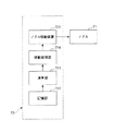
図1は、本発明の支持装置を備える表面加工装置の第1実施形態を示す図、図2は、図1に示す表面加工装置が備えるチャッキングプレートの平面図、図3は、図2に示すチャッキングプレートの拡大断面図、図4は、図1に示す表面加工装置が有する制御部の構成を示すブロック図、図5は、図2に示すチャッキングプレートの拡大断面図、図6ないし図8は、図1に示す表面加工装置の変形例を示す図である。なお、以下の説明では、図1中の上側を「上」、下側を「下」と言う。
Hereinafter, a supporting device and an etching method of the present invention will be described in detail based on embodiments shown in the accompanying drawings.
First, a surface processing apparatus provided with the support apparatus of this invention is demonstrated.
FIG. 1 is a diagram showing a first embodiment of a surface processing apparatus provided with a support device of the present invention, FIG. 2 is a plan view of a chucking plate provided in the surface processing apparatus shown in FIG. 1, and FIG. 4 is an enlarged cross-sectional view of the chucking plate shown in FIG. 4, FIG. 4 is a block diagram showing the configuration of the control unit of the surface processing apparatus shown in FIG. 1, FIG. 5 is an enlarged cross-sectional view of the chucking plate shown in FIG. FIG. 8 is a view showing a modification of the surface processing apparatus shown in FIG. In the following description, the upper side in FIG. 1 is referred to as “upper” and the lower side is referred to as “lower”.
表面加工装置1は、ローカルウエットエッチングにより、ワーク(被処理物)10に対して所望のエッチング処理を行う装置である。
ワーク10の構成材料としては、特に限定されないが、例えば、石英ガラス、無アルカリガラス等の各種ガラス、水晶等の結晶性材料、アルミナ、シリカ、チタニア等の各種セラミックス、シリコン、ガリウム−ヒ素等の各種半導体材料、ダイヤモンド、黒鉛等の炭素系材料、ポリエチレン、ポリスチレン、ポリカーボネート、ポリエチレンテレフタレート、液晶ポリマー、フェノール樹脂、アクリル樹脂等各種プラスチック(樹脂材料)のような誘電体材料で構成されたもの、その他、例えば、アルミニウム、銅、鉄系金属のような各種金属材料が挙げられる。
また、ワーク10の形状は、特に限定されず、例えば、板状、ブロック状等であってもよい。また、ワーク10の平面視形状としても特に限定されず、例えば、正方形、長方形、円形等であってもよい。なお、以下では、説明の便宜上、ワーク10として、板状をなし、平面視形状が略正方形であるものについて代表して説明する。
The
Although it does not specifically limit as a constituent material of the workpiece |
Moreover, the shape of the workpiece |
図1に示すように、表面加工装置1は、ワーク10を支持する支持装置(本発明の支持装置)2と、ワーク10の被処理面101にエッチング液を供給するエッチング液供給手段7とを有している。また、支持装置2は、ワーク10を支持するチャッキングプレート(支持台)3と、チャッキングプレート3の支持面31に開放する吸引孔4と、吸引孔4内を減圧し吸引孔4からエッチング液を吸引する吸引手段5と、チャッキングプレート3にワーク10を固定する固定手段6とを有している。
As shown in FIG. 1, the
表面加工装置1は、固定手段6によってワーク10をチャッキングプレート3に固定した状態にて、エッチング液供給手段7によってワーク10の被処理面101にエッチング液を供給しつつ、吸引手段5の作動により吸引孔4を減圧し吸引孔4から被処理面101と反対側の面(以下、「裏面102」とも言う)に回り込んだエッチング液を吸引することにより、ワーク10に対して所望のエッチング処理を行う装置である。
The
以下、支持装置2およびエッチング液供給手段7について、順次詳細に説明する。
まず、支持装置2について説明する。
支持装置2は、前述したように、チャッキングプレート3と、吸引孔4と、吸引手段5と、固定手段6とを有している。
図1に示すように、チャッキングプレート3は、板状をなしている。また、図2に示すように、チャッキングプレート3の平面視形状は、略長方形である。ただし、チャッキングプレート3の形状は、ワーク10を載置することができれば特に限定されず、例えば、板状でなくてもよいし、平面視形状が正方形、円形、異形等であってもよい。
Hereinafter, the
First, the
As described above, the
As shown in FIG. 1, the chucking
チャッキングプレート3の下面は、ワーク10を支持する支持面(チャッキング面)31を構成する。支持面31は、平坦面で構成されているのが好ましい。これにより、ワーク10を支持面31に支持したとき、ワーク10が支持面31の形状に倣って変形するのを防止することができる。また、ワーク10を支持面31に支持したときに、支持面31とワーク10との間に隙間が形成され難いため、エアチャッキングを用いる固定手段6によって、確実かつ簡単に、ワーク10を支持面31に固定することができる。
The lower surface of the
次いで、吸引孔4について説明する。
吸引孔4は、ワーク10に対するエッチング処理を行っている最中に、ワーク10の裏面102に回り込んできたエッチング液を吸引するための孔である。図1および図2に示すように、吸引孔4は、支持面31に開放する溝部41と、溝部41の内面に開放する複数のスリット(孔部)42とを有している。
Next, the
The
図2に示すように、溝部41は、支持面31に固定された状態のワーク10の縁部に沿って形成されている。また、溝部41は、環状をなしており、ワーク10の縁部の全周にわたって形成されている。このように、溝部をワーク10の縁部の全周にわたって形成することにより、裏面102の縁部の全域において、裏面102に回り込んできたエッチング液を吸引孔4から吸引することができる。
As shown in FIG. 2, the
また、図2および図3に示すように、溝部41は、その一部がワーク10と重なり合うように形成されている。言換すれば、支持面31に固定されたワーク10の縁部によって、溝部41の開口の一部が塞がれている。さらに換言すれば、溝部41は、ワーク10が支持面31に固定されている状態にて、その内周411がワーク10に含まれ(ワーク10の内側に位置し)、外周412がワーク10に含まれない(ワーク10の外側に位置する)ように形成されている。これにより、ワーク10の側面を伝って裏面102に回り込んだエッチング液が、溝部41の開口直下を濡れ広がっていくので、このエッチング液を吸引孔4からより確実に吸引することができる。
また、図3に示すように、溝部41は、矩形(長方形)の横断面形状を有している。なお、溝部41の横断面形状としては、特に限定されず、例えば、半円形であってもよいし、三角形であってもよい。
As shown in FIGS. 2 and 3, the
Moreover, as shown in FIG. 3, the
ここで、溝部41の幅Wとしては、特に限定されないが、1mm以上、10mm以下であるのが好ましい。幅Wをこのような範囲とすることにより、比較的簡単に、支持面31に固定されたワーク10の縁部によって溝部41の開口の一部が塞がれた状態とすることができる。すなわち、支持面31に固定されたワーク10によって、溝部41の開口の全域が塞がれてしまったり、反対に溝部41の開口が全く塞がれなかったりするのをより確実に防止することができる。その結果、裏面102に回り込んできたエッチング液を吸引孔4から効率的に吸引することができる。これに加えて、溝部41の内部空間(体積)を比較的小さくすることができるため、吸引手段5を作動させたときに溝部41内を比較的少ないエネルギーで減圧することができる(すなわち、吸引手段5の省エネ駆動を行うことができる)。
Here, the width W of the
また、溝部41の深さDとしては、特に限定されないが、0.1mm以上、1mm以下程度であるのが好ましい。深さDをこのような範囲とすることにより、裏面102に回り込もうとするエッチング液をより確実に溝部41内(溝部41直下)に回り込ませることができる。これに加えて、溝部41の内部空間(体積)を比較的小さくすることができるため、吸引手段5を作動させたときに溝部41内を比較的少ないエネルギーで減圧することができる。
Further, the depth D of the
また、ワーク10の溝部41と重なり合っている部分(溝部41上に突出している部分)の長さLとしては、特に限定されないが、例えば、0.5mm以上、5mm以下程度であるのが好ましい。長さLをこのような範囲とすることにより、ワーク10の裏面102に回り込んできたエッチング液を速やかに吸引孔4から吸引することができる。換言すれば、裏面102にエッチング液が留まるのを防止することができる。そのため、裏面102に対して不本意なエッチングが行われるのを防止することができる。
Further, the length L of the portion overlapping the
図2および図3に示すように、各スリット42は、チャッキングプレート3の平面視にて長手形状をなし、溝部41の延在方向(周方向)に沿って形成されている。また、各スリット42は、溝部41の底面とチャッキングプレート3の上面(支持面31と反対側の面)とを貫通するように設けられている。
また、各スリット42は、チャッキングプレート3の平面視にて、支持面31に固定されたワーク10に含まれるように形成されている。すなわち、各スリット42の開口が、ワーク10の裏面102の直上に位置するため、裏面102に回り込んできたエッチング液を吸引孔4により、確実に吸引することができる。
As shown in FIGS. 2 and 3, each slit 42 has a longitudinal shape in plan view of the
Each slit 42 is formed so as to be included in the
ここで、各スリット42の幅W1としては、特に限定されないが、例えば、0.5mm以上、5mm以下程度であるのが好ましい。W1をこのような範囲とすることにより、各スリット42の内部空間を比較的小さくすることができるため、吸引手段5を作動させたときに各スリット42内を比較的少ないエネルギーで減圧することができる。そのため、裏面102に回り込んできたエッチング液を吸引孔4から効率的に吸引することができる。
以上、吸引孔4について説明した。本実施形態のように、吸引孔4を溝部41とスリット42とで構成することにより、吸引孔4の内部空間をより小さくすることができる。そのため、吸引孔4内を減圧させ易く、裏面102に回り込んだエッチング液を効率的に吸引することができる。
Here, the width W1 of each slit 42 is not particularly limited, but is preferably about 0.5 mm or more and 5 mm or less, for example. By setting W1 in such a range, the internal space of each slit 42 can be made relatively small. Therefore, when the suction means 5 is operated, the inside of each slit 42 can be decompressed with relatively little energy. it can. Therefore, the etching solution that has entered the
The
次いで、吸引手段5について説明する。
吸引手段5は、エッチング液供給手段7が有する後述するエッチング液循環装置73の構成要素の一部を利用している。言い換えれば、エッチング液循環装置73が、吸引手段5を兼ねている。図1に示すように、吸引手段5は、吸引孔4と貯留タンク733とを連通する回収管738と、貯留タンク733を減圧する吸引ポンプ737とを有している。このような吸引手段5は、吸引ポンプ737を作動させて貯留タンク733内を減圧することにより、回収管738内および吸引孔4内を減圧し、それにより、ワーク10の裏面102に回り込んできたエッチング液(チャッキングプレート3とワーク10の間に侵入しようとするエッチング液)を吸引する。
Next, the suction unit 5 will be described.
The suction means 5 uses some of the constituent elements of an
次いで、固定手段6について説明する。
固定手段6は、支持面31にワーク10を固定する機能を有する。ワーク10を支持面31に固定することにより、チャッキングプレート3に対するワーク10の姿勢および位置をエッチング処理中一定に保つことができるため、ワーク10に対して所望のエッチング処理を行うことができる。特に、本実施形態のような表面加工装置1では、ワーク10をチャッキングプレート3に吊り下げるように支持するため、固定手段6により、ワーク10のチャッキングプレート3からの落下を防止することができる。
Next, the fixing means 6 will be described.
The fixing means 6 has a function of fixing the
図1に示すように、固定手段6は、チャッキングプレート3の支持面31に開放する複数の吸気孔61と、各吸気孔61に接続された吸引ポンプ62とを有している。図2に示すように、複数の吸気孔61は、マトリクス状に配置されている。また、各吸気孔61の開口は、ワーク10を支持面31に支持した状態にて、ワーク10によって塞がれる。このような固定手段6は、支持面31にワーク10を支持した状態にて、吸引ポンプ62を作動し、各吸気孔61内を減圧することにより、ワーク10を支持面31に固定する。このような構成の固定手段6によれば、簡単にワーク10を支持面31に固定することができる。また、吸気孔61内を常圧に復帰させるだけで、ワーク10を支持面31から簡単に取り外すことができる。
As shown in FIG. 1, the fixing means 6 has a plurality of intake holes 61 opened to the
次いで、エッチング液供給手段7について説明する。
エッチング液供給手段7は、ワーク10の被処理面101にエッチング液を供給し、ワーク10に対して所望のエッチング処理を行う機能を有している。図1に示すように、エッチング液供給手段7は、ワーク10の被処理面101に沿って移動可能に設けられたノズル71と、ノズル71の移動を制御する制御部72と、エッチング液をノズル71から送出し、回収するエッチング液循環装置73とを有している。
Next, the etching solution supply means 7 will be described.
The etching solution supply means 7 has a function of supplying an etching solution to the
ノズル71は、チャッキングプレート3の下方に設けられている。ノズル71は、外管711と、その内部に設けられた内管712とを有している。このノズル71では、エッチング液は、内管712を通ってノズル71の上端から送出され、内管712と外管711の間の隙間713を通って回収される。
エッチング液循環装置73は、エッチング液をノズル71から送出する送出管731と、エッチング液をノズル71から回収する回収管732と、エッチング液を吸引孔4から回収する回収管738と、エッチング液を貯留する貯留タンク733と、貯留タンク733から送出管731へエッチング液を送出する送液ポンプ734と、送出管731へ送出するエッチング液の流量を調節する流量調節バルブ735および流量計736と、ワーク10の被処理面101に付着したエッチング液および裏面102に回り込んだエッチング液を吸引して回収するための吸引ポンプ737とを有している。
The
The etching
これら各装置は、貯留タンク733、送液ポンプ734、流量調節バルブ735、流量計736、送出管731(ノズル71)、回収管732、738の順に接続され、回収管732、738と貯留タンク733が接続されることにより、循環経路が形成されている。吸引ポンプ737は貯留タンク733内を減圧することにより、外管711(隙間713)からエッチング液を吸引するとともに、吸引孔4からエッチング液を吸引する。送出管731および回収管732には、ノズル71の移動に追従可能なように可撓性があるものを用いる。また、エッチング液が接触する部分は全て、エッチング液により腐食することのない材料から成る。
These devices are connected in the order of a
図4に示すように、制御部72は、ノズル71を平面内(被処理面101上)で移動させるノズル移動装置721と、加工前および目標とする加工後のワーク10の表面のプロファイルを記憶する記憶部722、これら2つのプロファイルおよびエッチング液の単位時間当たりのエッチング量(加工深さ)から、ノズル71の移動速度を算出する演算部723、その演算結果に基づきノズル71の移動速度を制御するとともにノズル71とワーク10の距離を一定に保つようにノズル移動装置721を制御する移動制御部724とを有している。
以上、表面加工装置1について説明した。
As illustrated in FIG. 4, the
The
次いで、表面加工装置1の動作(本発明のエッチング方法)について説明する。
[テスト工程]
まず、表面加工装置1を使用する前に、予備実験として、ワーク10と同じ材料から成る試料(テストピース)を用いて、ノズル71から所定の一定流量のエッチング液を試料表面に送出した場合における単位時間当たりのエッチング深さ(エッチングされる深さ)を求めておく。また、このエッチング深さの測定をノズル71を一定の速度で移動させながら行う。そして、この測定を複数の速度で行うことにより、ノズル71の移動速度とエッチング深さの関係を求めることができる。ワーク10の被処理面101上の各点におけるエッチングすべき加工深さが決まれば、ここで求めたノズル71の移動速度と加工深さの関係から、ノズル71の移動速度を定めることができる。
Next, the operation of the surface processing apparatus 1 (the etching method of the present invention) will be described.
[Test process]
First, before using the
[エッチング前のワーク10の形状測定工程]
次に、ワーク10の被処理面101の加工前のプロファイルを測定する。この測定は、既存の表面形状測定装置や表面粗さ測定装置等を用いて行うことができる。得られた測定結果を制御部72の記憶部722に記憶させる。次に、演算部723は、記憶部722に記憶されたワーク10の被処理面101の加工前および目標とする加工後のワーク10の被処理面101のプロファイルとの差から、ワーク10の被処理面101上の各位置において加工すべきエッチング深さを算出する。演算部723は更に、前述のノズル71の移動速度とエッチング深さの関係から、被処理面101上の各位置におけるノズル71の移動速度を算出する。
[Process for measuring shape of
Next, the profile before processing of the
[ワーク10を支持する工程]
次いで、表面加工装置1のチャッキングプレート3(支持面31)に、ワーク10を被処理面101がノズル71と対向するように支持し、固定手段6により、ワーク10を支持面31に固定する。
[エッチング工程]
次いで、制御部72が有するノズル移動装置721によって、ノズル71を被処理面101からずれた位置(被処理面101の直下ではない位置)に移動させる。この状態にて、送液ポンプ734を作動させて流量調節バルブ735を調節することにより、貯留タンク733からノズル71を通して、所定の一定流量でエッチング液を送出する。ノズル71からエッチング液を送出させた直後は、ノズル71から送出するエッチング液の流量が不安定となり易いため、上述のように、ノズル71を被処理面101の下方からずらした状態で、エッチング液を送出し、エッチング液の流量(送出量)が所定の流量に保たれるまでこの状態を維持するのが好ましい。
[Step of supporting workpiece 10]
Next, the
[Etching process]
Next, the
次いで、ノズル71を被処理面101と対向する位置に移動させるとともに、移動制御部724により制御されたノズル移動装置721によって、ノズル71を上述のように定めた速度で、ワーク10の被処理面101の全域を通過するように、例えば蛇行させるようにして移動させる。それとともに、吸引ポンプ737を作動させてワーク10の被処理面101からエッチング液を貯留タンク733に吸引しつつ、吸引孔4から、ワーク10の裏面102に回り込んできたエッチング液を吸引する。これにより、裏面102に対する不本意なエッチングが防止された状態で、ワーク10の被処理面101の各点において、前述の算出された加工すべき深さにエッチングがなされ、所望のプロファイルが得られる。
Next, the
具体的には、例えばノズル71が被処理面101の縁部に位置する場合、図5に示すように、ノズル71から送出されるエッチング液の一部が、被処理面101に供給される(付着する)ことなく、裏面102に回り込む場合がある。このような場合、従来では、裏面102に回り込んだエッチング液によって裏面102がエッチングされ、エッチング後のワーク10の形状が所望のものと異なると言った問題や、吸気孔61からエッチング液が装置内に侵入し、装置を腐食させると言った問題が発生していた。
Specifically, for example, when the
しかしながら、表面加工装置1によれば、裏面102に回り込んだエッチング液を吸引孔4から素早く吸引することができる。そのため、裏面102にエッチング液が長時間付着するのを防止でき、裏面102に対する不本意なエッチングを防止することができる。その結果、エッチング後のワーク10の形状を所望のものとすることができる。特に、エッチング後のワーク10の厚さを所望の厚さとすることができるため、例えば、ワーク10が、水晶のATカット板のような、厚さによって周波数特性が大きく変化するものである場合に特に有効である。
However, according to the
また、表面加工装置1によれば、裏面102に回り込んできたエッチング液を裏面102と支持面31との間に侵入する前に吸引孔4から吸引することができる。そのため、吸気孔61内にエッチング液が侵入するのを防止でき、固定手段6が有する各種装置がエッチング液により腐食するのを防止することができる。
また、本実施形態では、吸引孔4から吸引したエッチング液を貯留タンク733に回収するため、エッチング液を有効利用(再利用)することができる。すなわち、表面加工装置1によれば、ワーク10のエッチング処理を低コストで行うことができる。
以上、第1実施形態の表面加工装置1について説明した。
Further, according to the
Moreover, in this embodiment, since the etching liquid sucked from the
The
第1実施形態では、エッチング液供給手段7が1つのノズル71を有する形態について説明したが、エッチング液供給手段7の構成としてはこれに限定されず、例えば図6(a)に示すように、1列に並んだ複数のノズル71を有するノズル集合体74を有しており、ノズル集合体74が、ワーク10の被処理面101に沿って、ノズル71の配列方向に直交する方向に移動可能となっている構成であってもよい。また、図6(b)に示すように、複数の内管712を1列に並べ、全ての内管712の外周を覆うように1つの外管711を形成したノズル集合体74を用いた構成であってもよい。
In the first embodiment, the configuration in which the etching
また、第1実施形態では、吸引孔4が環状の1つの溝部41を有する形態について説明したが、溝部41の数としては、前述したような機能を発揮することができれば、これに限定されない。例えば、図7(a)に示すように、ワーク10の各辺に対応するように設けられた4つの溝部41を有していてもよいし、図7(b)に示すように、略「コ」の字状の2つの溝部41を有していてもよい。なお、図7では、説明の便宜上、吸気孔61の図示を省略している。
Moreover, although 1st Embodiment demonstrated the form in which the
また、第1実施形態では、吸引孔4が8つのスリット42を有する形態について説明したが、スリット42の数としては、前述したような機能を発揮することができれば、これに限定されない。例えば、図7(a)に示すように、ワーク10の各辺に対応するように設けられた4つのスリット42を有していてもよいし、図7(b)に示すように、略「コ」の字状の2つのスリットを有していてもよいし、図8に示すように、環状のスリット42を1つ有していてもよい。ただし、図8に示す場合には、チャッキングプレート3の内側と外側とが吸引孔4により分離してしまうため、この分離を防止する手段を取ることが必要である。なお、図8では、説明の便宜上、吸気孔61の図示を省略している。
In the first embodiment, the
また、第1実施形態では、固定手段6とエッチング液供給手段7とで、別々の吸引ポンプ62、737を使用しているが、固定手段6とエッチング液供給手段7とで1つの吸引ポンプ(例えば吸引ポンプ737)を使用してもよい。
また、第1実施形態では、吸引孔4から吸引したエッチング液を貯留タンク733に回収しているが、これに限定されず、吸引孔4から吸引したエッチング液を廃棄してもよい。この場合、吸引手段5は、エッチング液循環装置73と別に設ければよい。
In the first embodiment,
In the first embodiment, the etching solution sucked from the
<第2実施形態>
次に、本発明の支持装置を備える表面加工装置の第2実施形態について説明する。
図9は、本発明の支持装置を備える表面加工装置の第2実施形態を示す図、図10は、図9に示す表面加工装置が備えるチャッキングプレートの部分拡大断面図である。
以下、第2実施形態の表面加工装置について、前述した実施形態との相違点を中心に説明し、同様の事項については、その説明を省略する。
本発明の第2実施形態にかかる表面加工装置では、ワークの裏面に回り込んだエッチング液の除去方法が異なる以外は、前述した第1実施形態と同様である。なお、図9および図10にて、前述した第1実施形態と同様の構成には、同一符号を付してある。
Second Embodiment
Next, 2nd Embodiment of a surface processing apparatus provided with the support apparatus of this invention is described.
FIG. 9 is a view showing a second embodiment of the surface processing apparatus including the support device of the present invention, and FIG. 10 is a partially enlarged sectional view of the chucking plate included in the surface processing apparatus shown in FIG.
Hereinafter, the surface processing apparatus according to the second embodiment will be described with a focus on differences from the above-described embodiment, and description of similar matters will be omitted.
The surface processing apparatus according to the second embodiment of the present invention is the same as that of the first embodiment described above except that the method of removing the etching solution that has entered the back surface of the workpiece is different. In FIG. 9 and FIG. 10, the same reference numerals are given to the same configurations as those in the first embodiment described above.
図9に示すように、第2実施形態の表面加工装置1Aは、チャッキングプレート(支持台)3に形成された噴出孔9と、噴出孔9から気体を噴出させる(噴出孔9内を加圧する)噴出手段8とを有している。このような表面加工装置1Aは、裏面102に回り込んできたエッチング液を噴出孔9から噴出させた気体(気流)によって吹き飛ばすようにして除去するように構成されている。
As shown in FIG. 9, the
噴出孔9の構成は、前述した第1実施形態の吸引孔4と同様の構成である。すなわち、図9および図10に示すように、噴出孔9は、支持面31に開放する環状の溝部91と、溝部91の内面に開放する複数のスリット92とを有し、溝部91およびスリット92は、それぞれ、前述した第1実施形態の吸引孔4が有する溝部41およびスリット42と同様の構成をなしている。そのため、噴出孔9については、その説明を省略する。
The structure of the
噴出手段8は、送出ポンプ81と、送出ポンプ81と各スリット92とを連通する連結管82とを有している。このような噴出手段8は、例えば送出ポンプにより外気等の気体を連結管82を介して噴出孔9内に送り込み、送り込んだ気体を噴出孔9からワーク10に向けて噴出させる。噴出孔9から噴出した気体により、図9中の矢印で示すような気流が発生し、いわゆるエアカーテンが形成される。これにより、裏面102に回り込んできたエッチング液を前記気流により吹き飛ばすようにして除去することができる。さらには、裏面102にエッチング液が回り込むこと自体を、前記気流により防止することができる。
The ejection means 8 includes a
特に、溝部91が、その一部がワーク10と重なり合うように形成されており、スリット92がチャッキングプレート3の平面視にて支持面31に固定されたワーク10に含まれるように形成されているため、噴出孔9から噴出された気体をワーク10の裏面102の縁部に当てることができる。そのため、上述した効果がより顕著となる。
また、溝部91が、支持面31に固定されたワーク10の縁部の全域にわたって形成されているため、ワーク10の裏面102の縁部の全域に前記気流を発生させることができる。そのため、裏面102の縁部の全域において、エッチング液を除去することができる。
次いで、表面加工装置1Aの作動(本発明のエッチング方法)について説明する。なお、[テスト工程]、[エッチング前のワーク10の形状測定工程]および[ワーク10を支持する工程]については、第1実施形態と同様であるため、その説明を省略する。
In particular, the
Further, since the
Next, the operation of the
[エッチング工程]
制御部72が有するノズル移動装置721によって、ノズル71を被処理面101からずれた位置(被処理面101の直下ではない位置)に移動させる。この状態にて、送液ポンプ734を作動させて流量調節バルブ735を調節することにより、貯留タンク733からノズル71を通して、所定の一定流量でエッチング液を送出する。
[Etching process]
A
次いで、ノズル71を被処理面101と対向する位置に移動させるとともに、移動制御部724により制御されたノズル移動装置721によって、ノズル71を上述のように定めた速度で、ワーク10の被処理面101の全域を通過するように、例えば蛇行させるようにして移動させる。それとともに、吸引ポンプ737を作動させてワーク10の被処理面101からエッチング液を貯留タンク733に吸引しつつ、送出ポンプ81を作動させて噴出孔9からワーク10の裏面102に向けて気体を噴出させる。これにより、裏面102に回り込んできたエッチング液を除去することができ、裏面102に対する不本意なエッチングが防止された状態で、ワーク10の被処理面101の各点において、前述の算出された加工すべき深さにエッチングがなされ、所望のプロファイルが得られる。
以上のような第2実施形態によっても、第1実施形態と同様の効果を発揮することができる。
Next, the
According to the second embodiment as described above, the same effect as that of the first embodiment can be exhibited.
<第3実施形態>
次に、本発明の支持装置を備える表面加工装置の第3実施形態について説明する。
図11は、本発明の支持装置を備える表面加工装置の第3実施形態を示す図である。
以下、第3実施形態の表面加工装置について、前述した実施形態との相違点を中心に説明し、同様の事項については、その説明を省略する。
本発明の第3実施形態にかかる表面加工装置では、噴出手段の構成が異なる以外は、前述した第2実施形態と同様である。なお、図11にて、前述した第1実施形態および第2実施形態と同様の構成には、同一符号を付してある。
<Third Embodiment>
Next, a third embodiment of the surface processing apparatus provided with the support device of the present invention will be described.
FIG. 11: is a figure which shows 3rd Embodiment of a surface processing apparatus provided with the support apparatus of this invention.
Hereinafter, the surface processing apparatus of the third embodiment will be described with a focus on differences from the above-described embodiments, and description of similar matters will be omitted.
The surface processing apparatus according to the third embodiment of the present invention is the same as the second embodiment described above except that the configuration of the ejection means is different. In FIG. 11, the same reference numerals are given to the same configurations as those of the first embodiment and the second embodiment described above.
図11に示すように、本実施形態の噴出手段8Bは、固定手段6が有する吸引ポンプ62と、吸引ポンプ62および噴出孔9を連結する連結管82とを有している。このような噴出手段8Bでは、支持面31にワーク10を固定する際に吸引ポンプ62により吸引された気体(空気)を、連結管82を介して噴出孔9から噴出させるように構成されている。
As shown in FIG. 11, the ejection means 8 </ b> B of the present embodiment includes a
噴出手段8Bをこのような構成とすることにより、ワーク10の支持面31に固定すると同時に、噴出孔9から気体が噴出されるため、例えば、噴出孔9から気体を噴出させるのを忘れたり、ワーク10を固定してから噴出孔9から気体が噴出されるまでの間に時間がかかったりすることにより、裏面102に対して不本意なエッチングがされてしまうのを確実に防止することができる。また、表面加工装置1Bの部品点数を削減することができる。
By making the ejection means 8B in such a configuration, the gas is ejected from the
なお、さらに、貯留タンク733内を減圧する吸引ポンプ737と連結管82とを連結し、吸引ポンプ737で吸引した気体を連結管82を介して噴出孔9から噴出させるようにしてもよい。これにより、噴出孔9から噴出させる気体の流速をより速くすることができるため、上述の効果がより顕著となる。
以上のような第3実施形態によっても、第1実施形態と同様の効果を発揮することができる。
Further, a
According to the third embodiment as described above, the same effect as that of the first embodiment can be exhibited.
<第4実施形態>
次に、本発明の支持装置を備える表面加工装置の第4実施形態について説明する。
図12は、本発明の支持装置を備える表面加工装置の第4実施形態を示す部分拡大断面図である。
以下、第4実施形態の表面加工装置について、前述した実施形態との相違点を中心に説明し、同様の事項については、その説明を省略する。
本発明の第4実施形態にかかる表面加工装置では、噴出孔が有するスリットの姿勢が異なる以外は、前述した第2実施形態と同様である。なお、図12にて、前述した第1実施形態および第2実施形態と同様の構成には、同一符号を付してある。
<Fourth embodiment>
Next, a fourth embodiment of the surface processing apparatus provided with the support device of the present invention will be described.
FIG. 12 is a partial enlarged cross-sectional view showing a fourth embodiment of the surface processing apparatus including the support device of the present invention.
Hereinafter, the surface processing apparatus according to the fourth embodiment will be described with a focus on differences from the above-described embodiment, and description of similar matters will be omitted.
The surface processing apparatus according to the fourth embodiment of the present invention is the same as the above-described second embodiment except that the posture of the slits of the ejection holes is different. In FIG. 12, the same reference numerals are given to the same configurations as those in the first embodiment and the second embodiment described above.
図12に示すように、本実施形態の表面加工装置1Cでは、噴出孔9が有するスリット92Cが、溝部91側の開口が支持面31の法線に対してワーク10の外側に向くように傾いている。そして、スリット92Cの開口からワーク10の縁に向けて気体が噴出されるようになっている。このような構成により、エッチング液がワーク10の裏面102に回り込む前に、そのエッチング液を気流(スリット92Cから噴出された気体)により吹き飛ばすように除去することができる。
以上のような第4実施形態によっても、第1実施形態と同様の効果を発揮することができる。
As shown in FIG. 12, in the
According to the fourth embodiment as described above, the same effect as that of the first embodiment can be exhibited.
<第5実施形態>
次に、本発明の支持装置を備える表面加工装置の第5実施形態について説明する。
図13は、本発明の支持装置を備える表面加工装置の第5実施形態を示す部分拡大断面図である。
以下、第5実施形態の表面加工装置について、前述した実施形態との相違点を中心に説明し、同様の事項については、その説明を省略する。
本発明の第5実施形態にかかる表面加工装置では、噴出孔から噴出された気体により吹き飛ばされたエッチング液を回収する回収手段が設けられている以外は、前述した第2実施形態と同様である。なお、図12にて、前述した第1実施形態および第2実施形態と同様の構成には、同一符号を付してある。
<Fifth Embodiment>
Next, a fifth embodiment of the surface processing apparatus provided with the support device of the present invention will be described.
FIG. 13: is a partial expanded sectional view which shows 5th Embodiment of a surface processing apparatus provided with the support apparatus of this invention.
Hereinafter, the surface processing apparatus according to the fifth embodiment will be described with a focus on differences from the above-described embodiment, and description of similar matters will be omitted.
The surface processing apparatus according to the fifth embodiment of the present invention is the same as the second embodiment described above except that a recovery means for recovering the etching solution blown off by the gas ejected from the ejection holes is provided. . In FIG. 12, the same reference numerals are given to the same configurations as those in the first embodiment and the second embodiment described above.
図13に示すように、本実施形態の表面加工装置1Dは、噴出孔9から噴出された気体により吹き飛ばされたエッチング液を回収する回収手段83を有している。回収手段83は、ワーク10の縁部に向けられたノズル831と、ノズル831および貯留タンク733を連結する回収管832とを有している。このような回収手段83は、吸引ポンプ737の作動により貯留タンク733を減圧することにより、ノズル831からワーク10の縁部付近の気体とともに、噴出孔9から噴出された気体によって吹き飛ばされたエッチング液を吸引するように構成されている。このような回収手段83を有することにより、エッチング液が装置内に飛散するのを防止することができるとともに、エッチング液を再利用することができる。
以上のような第5実施形態によっても、第1実施形態と同様の効果を発揮することができる。
As shown in FIG. 13, the
According to the fifth embodiment as described above, the same effect as that of the first embodiment can be exhibited.
以上、本発明の支持装置およびエッチング方法を、図示の実施形態に基づいて説明したが、本発明はこれらに限定されるものではなく、各部の構成は、同様の機能を有する任意の構成のものに置換することができる。また、他の任意の構成物や、工程が付加されていてもよい。また、前述した各実施形態を適宜組み合わせてもよい。
また、前述した実施形態では、表面加工装置がローカルウエットエッチングによりワークをエッチングする装置について説明したが、これに限定されず、表面加工装置がディップ法によりワークをエッチングする装置であってもよい。
As mentioned above, although the support apparatus and etching method of this invention were demonstrated based on embodiment of illustration, this invention is not limited to these, The structure of each part is the thing of arbitrary structures which have the same function Can be substituted. Moreover, other arbitrary structures and processes may be added. Moreover, you may combine each embodiment mentioned above suitably.
In the above-described embodiment, the surface processing apparatus is described as an apparatus for etching a workpiece by local wet etching. However, the present invention is not limited to this, and the surface processing apparatus may be an apparatus for etching a workpiece by a dipping method.
1、1A、1B、1C、1D……表面加工装置 2……支持装置 3……チャッキングプレート 31……支持面 4……吸引孔 41……溝部 411……内周 412……外周 42……スリット 5……吸引手段 6……固定手段 61……吸気孔 62……吸引ポンプ 7……エッチング液供給手段 71……ノズル 711……外管 712……内管 713……隙間 72……制御部 721……ノズル移動装置 722……記憶部 723……演算部 724……移動制御部 73……エッチング液循環装置 731……送出管 732……回収管 733……貯留タンク 734……送液ポンプ 735……流量調節バルブ 736……流量計 737……吸引ポンプ 738……回収管 74……ノズル集合体 8、8B……噴出手段 81……送出ポンプ 82……連結管 83……回収手段 831……ノズル 832……回収管 9……噴出孔 91……溝部 92、92C……スリット 10……ワーク 101……被処理面 102……裏面
1, 1A, 1B, 1C, 1D ...
Claims (10)
前記被処理物の被処理面の裏面側を支持する支持面と、
前記支持面に開放して前記支持面に前記被処理物を支持した状態にて、平面視で前記被処理物の縁部の少なくとも一部と重なる位置にある開口部と、を有する支持台と、
前記開口部から前記エッチング液を吸引する吸引手段と、を備えていることを特徴とする支持装置。 A support device for supporting the object to be processed when a desired etching process is performed on the object to be processed by supplying an etching solution to the object to be processed,
A support surface for supporting the back side of the surface to be processed of the object to be processed;
A support base having an opening at a position overlapping with at least a part of the edge of the object to be processed in plan view in a state where the object to be processed is supported on the support surface by opening to the support surface; ,
And a suction means for sucking the etching solution from the opening.
前記被処理物の被処理面の裏面側を支持する支持面と、
前記支持面に開放して前記支持面に前記被処理物を支持した状態にて、平面視で前記被処理物の縁部と一部が重なり、他の部分が前記被処理物の縁部から外側に露出する位置にある開口部と、を有する支持台と、
前記開口部から気体を噴射させる噴射手段と、を備えていることを特徴とする支持装置。 A support device for supporting the object to be processed when a desired etching process is performed on the object to be processed by supplying an etching solution to the object to be processed,
A support surface for supporting the back side of the surface to be processed of the object to be processed;
In a state where the object to be processed is supported on the support surface by opening to the support surface, a part of the edge of the object to be processed overlaps in plan view, and the other part is separated from the edge of the object to be processed. An opening at a position exposed to the outside, a support base,
And a jetting device for jetting gas from the opening.
前記被処理物にエッチング液を供給することにより前記被処理物に対して所望のエッチング処理を行うエッチング工程と、を含み、
前記エッチング工程では、前記支持面に開放して、前記支持された前記被処理物の縁部の少なくとも一部と平面視で重なる位置に形成されている開口部から前記エッチング液を吸引することを特徴とするエッチング方法。 A supporting step of supporting the back side of the surface to be processed of the processing object on the supporting surface;
An etching step of performing a desired etching process on the object to be processed by supplying an etching solution to the object to be processed,
In the etching step, the etching solution is sucked from an opening formed at a position that opens to the support surface and overlaps at least a part of the edge of the supported object to be processed in plan view. Etching method characterized.
前記被処理物にエッチング液を供給することにより前記被処理物に対して所望のエッチング処理を行うエッチング工程と、を含み、
前記エッチング工程では、前記支持面に開放して、前記支持された前記被処理物の縁部と一部が重なり、他の部分が前記被処理物の縁部から外側に露出する位置に形成されている開口部から気体を噴出させることを特徴とするエッチング方法。 A supporting step of supporting the back side of the surface to be processed of the processing object on the supporting surface;
An etching step of performing a desired etching process on the object to be processed by supplying an etching solution to the object to be processed,
In the etching step, the support surface is opened, a part of the edge of the supported workpiece is overlapped, and the other part is formed at a position exposed to the outside from the edge of the workpiece. Etching method characterized by ejecting gas from the opening.
Priority Applications (1)
| Application Number | Priority Date | Filing Date | Title |
|---|---|---|---|
| JP2009293457A JP5690985B2 (en) | 2009-12-24 | 2009-12-24 | Support apparatus and etching method |
Applications Claiming Priority (1)
| Application Number | Priority Date | Filing Date | Title |
|---|---|---|---|
| JP2009293457A JP5690985B2 (en) | 2009-12-24 | 2009-12-24 | Support apparatus and etching method |
Publications (3)
| Publication Number | Publication Date |
|---|---|
| JP2011134913A JP2011134913A (en) | 2011-07-07 |
| JP2011134913A5 JP2011134913A5 (en) | 2013-02-07 |
| JP5690985B2 true JP5690985B2 (en) | 2015-04-01 |
Family
ID=44347326
Family Applications (1)
| Application Number | Title | Priority Date | Filing Date |
|---|---|---|---|
| JP2009293457A Expired - Fee Related JP5690985B2 (en) | 2009-12-24 | 2009-12-24 | Support apparatus and etching method |
Country Status (1)
| Country | Link |
|---|---|
| JP (1) | JP5690985B2 (en) |
Families Citing this family (1)
| Publication number | Priority date | Publication date | Assignee | Title |
|---|---|---|---|---|
| JP2014056950A (en) * | 2012-09-13 | 2014-03-27 | Lintec Corp | Retention device, and retention method |
Family Cites Families (4)
| Publication number | Priority date | Publication date | Assignee | Title |
|---|---|---|---|---|
| JPH1092712A (en) * | 1996-09-10 | 1998-04-10 | Sharp Corp | Semiconductor manufacturing device |
| JP2002124508A (en) * | 2000-10-13 | 2002-04-26 | Nec Corp | Spin treating apparatus for substrates |
| US6939206B2 (en) * | 2001-03-12 | 2005-09-06 | Asm Nutool, Inc. | Method and apparatus of sealing wafer backside for full-face electrochemical plating |
| JP2007115728A (en) * | 2005-10-18 | 2007-05-10 | Sumco Corp | Single wafer etching device and single wafer etching method |
-
2009
- 2009-12-24 JP JP2009293457A patent/JP5690985B2/en not_active Expired - Fee Related
Also Published As
| Publication number | Publication date |
|---|---|
| JP2011134913A (en) | 2011-07-07 |
Similar Documents
| Publication | Publication Date | Title |
|---|---|---|
| KR100642666B1 (en) | Nozzle cleaning apparatus and substrate processing apparatus | |
| TWI531446B (en) | Blasting method and apparatus having abrasive recovery system, processing method of thin-film solar cell panel, and thin-film solar cell panel processed by the method | |
| KR100796544B1 (en) | Etching method of single wafer | |
| US11660702B2 (en) | Laser apparatus including fastening holes and inlet grooves | |
| JP2005051028A (en) | Substrate supporting device and substrate removing method | |
| JP2020115513A (en) | Substrate processing method and substrate processing apparatus | |
| US9694453B2 (en) | Method and apparatus for physical confinement of a liquid meniscus over a semiconductor wafer | |
| JP5001391B2 (en) | Dust collector for scribe head | |
| JP5690985B2 (en) | Support apparatus and etching method | |
| US20140251539A1 (en) | Substrate processing apparatus and substrate processing method | |
| JP2012086301A (en) | Apparatus and method for producing semiconductor | |
| JP6632344B2 (en) | Wafer transfer device | |
| JP2008300454A (en) | Substrate-treating device and substrate treatment method | |
| JP2007196094A (en) | Treatment liquid supply unit and substrate treatment apparatus equipped with the same | |
| JP6012945B2 (en) | Substrate cutting device | |
| JP2010177424A (en) | Surface treatment device and surface treatment method | |
| JP2016119399A (en) | Cutting device and cutting method | |
| JP2008213103A (en) | Working fluid feeding device of wire saw | |
| JP5111999B2 (en) | Substrate processing equipment | |
| JP2009070996A (en) | Vacuum suction stage and semiconductor manufacturing method using the same | |
| JP7431601B2 (en) | laser processing equipment | |
| JP2006278367A (en) | Dust removing device and dust removal method | |
| KR101410038B1 (en) | Glass cutting apparatus | |
| JP5808182B2 (en) | Nozzle cleaner for laser processing equipment | |
| JP4854597B2 (en) | Substrate processing apparatus and substrate processing method |
Legal Events
| Date | Code | Title | Description |
|---|---|---|---|
| A711 | Notification of change in applicant |
Free format text: JAPANESE INTERMEDIATE CODE: A712 Effective date: 20110729 |
|
| RD03 | Notification of appointment of power of attorney |
Free format text: JAPANESE INTERMEDIATE CODE: A7423 Effective date: 20110729 |
|
| A521 | Written amendment |
Free format text: JAPANESE INTERMEDIATE CODE: A523 Effective date: 20110819 |
|
| A521 | Written amendment |
Free format text: JAPANESE INTERMEDIATE CODE: A523 Effective date: 20121213 |
|
| A621 | Written request for application examination |
Free format text: JAPANESE INTERMEDIATE CODE: A621 Effective date: 20121213 |
|
| A521 | Written amendment |
Free format text: JAPANESE INTERMEDIATE CODE: A821 Effective date: 20121213 |
|
| A977 | Report on retrieval |
Free format text: JAPANESE INTERMEDIATE CODE: A971007 Effective date: 20130725 |
|
| A131 | Notification of reasons for refusal |
Free format text: JAPANESE INTERMEDIATE CODE: A131 Effective date: 20130730 |
|
| A521 | Written amendment |
Free format text: JAPANESE INTERMEDIATE CODE: A523 Effective date: 20130918 |
|
| A131 | Notification of reasons for refusal |
Free format text: JAPANESE INTERMEDIATE CODE: A131 Effective date: 20140408 |
|
| A521 | Written amendment |
Free format text: JAPANESE INTERMEDIATE CODE: A523 Effective date: 20140606 |
|
| A01 | Written decision to grant a patent or to grant a registration (utility model) |
Free format text: JAPANESE INTERMEDIATE CODE: A01 Effective date: 20140819 |
|
| A711 | Notification of change in applicant |
Free format text: JAPANESE INTERMEDIATE CODE: A711 Effective date: 20140917 |
|
| A61 | First payment of annual fees (during grant procedure) |
Free format text: JAPANESE INTERMEDIATE CODE: A61 Effective date: 20140917 |
|
| A521 | Written amendment |
Free format text: JAPANESE INTERMEDIATE CODE: A821 Effective date: 20140917 |
|
| A521 | Written amendment |
Free format text: JAPANESE INTERMEDIATE CODE: A523 Effective date: 20141028 |
|
| R150 | Certificate of patent or registration of utility model |
Ref document number: 5690985 Country of ref document: JP Free format text: JAPANESE INTERMEDIATE CODE: R150 |
|
| S531 | Written request for registration of change of domicile |
Free format text: JAPANESE INTERMEDIATE CODE: R313531 |
|
| R350 | Written notification of registration of transfer |
Free format text: JAPANESE INTERMEDIATE CODE: R350 |
|
| LAPS | Cancellation because of no payment of annual fees |