JP5607427B2 - Charging vehicle allocation management server and charging vehicle allocation management system - Google Patents
Charging vehicle allocation management server and charging vehicle allocation management system Download PDFInfo
- Publication number
- JP5607427B2 JP5607427B2 JP2010125281A JP2010125281A JP5607427B2 JP 5607427 B2 JP5607427 B2 JP 5607427B2 JP 2010125281 A JP2010125281 A JP 2010125281A JP 2010125281 A JP2010125281 A JP 2010125281A JP 5607427 B2 JP5607427 B2 JP 5607427B2
- Authority
- JP
- Japan
- Prior art keywords
- charging
- vehicle
- management server
- charge
- dispatch
- Prior art date
- Legal status (The legal status is an assumption and is not a legal conclusion. Google has not performed a legal analysis and makes no representation as to the accuracy of the status listed.)
- Active
Links
Images


Classifications
-
- G—PHYSICS
- G06—COMPUTING OR CALCULATING; COUNTING
- G06Q—INFORMATION AND COMMUNICATION TECHNOLOGY [ICT] SPECIALLY ADAPTED FOR ADMINISTRATIVE, COMMERCIAL, FINANCIAL, MANAGERIAL OR SUPERVISORY PURPOSES; SYSTEMS OR METHODS SPECIALLY ADAPTED FOR ADMINISTRATIVE, COMMERCIAL, FINANCIAL, MANAGERIAL OR SUPERVISORY PURPOSES, NOT OTHERWISE PROVIDED FOR
- G06Q10/00—Administration; Management
- G06Q10/08—Logistics, e.g. warehousing, loading or distribution; Inventory or stock management
-
- B—PERFORMING OPERATIONS; TRANSPORTING
- B60—VEHICLES IN GENERAL
- B60L—PROPULSION OF ELECTRICALLY-PROPELLED VEHICLES; SUPPLYING ELECTRIC POWER FOR AUXILIARY EQUIPMENT OF ELECTRICALLY-PROPELLED VEHICLES; ELECTRODYNAMIC BRAKE SYSTEMS FOR VEHICLES IN GENERAL; MAGNETIC SUSPENSION OR LEVITATION FOR VEHICLES; MONITORING OPERATING VARIABLES OF ELECTRICALLY-PROPELLED VEHICLES; ELECTRIC SAFETY DEVICES FOR ELECTRICALLY-PROPELLED VEHICLES
- B60L3/00—Electric devices on electrically-propelled vehicles for safety purposes; Monitoring operating variables, e.g. speed, deceleration or energy consumption
- B60L3/12—Recording operating variables ; Monitoring of operating variables
-
- B—PERFORMING OPERATIONS; TRANSPORTING
- B60—VEHICLES IN GENERAL
- B60L—PROPULSION OF ELECTRICALLY-PROPELLED VEHICLES; SUPPLYING ELECTRIC POWER FOR AUXILIARY EQUIPMENT OF ELECTRICALLY-PROPELLED VEHICLES; ELECTRODYNAMIC BRAKE SYSTEMS FOR VEHICLES IN GENERAL; MAGNETIC SUSPENSION OR LEVITATION FOR VEHICLES; MONITORING OPERATING VARIABLES OF ELECTRICALLY-PROPELLED VEHICLES; ELECTRIC SAFETY DEVICES FOR ELECTRICALLY-PROPELLED VEHICLES
- B60L53/00—Methods of charging batteries, specially adapted for electric vehicles; Charging stations or on-board charging equipment therefor; Exchange of energy storage elements in electric vehicles
- B60L53/30—Constructional details of charging stations
- B60L53/305—Communication interfaces
-
- B—PERFORMING OPERATIONS; TRANSPORTING
- B60—VEHICLES IN GENERAL
- B60L—PROPULSION OF ELECTRICALLY-PROPELLED VEHICLES; SUPPLYING ELECTRIC POWER FOR AUXILIARY EQUIPMENT OF ELECTRICALLY-PROPELLED VEHICLES; ELECTRODYNAMIC BRAKE SYSTEMS FOR VEHICLES IN GENERAL; MAGNETIC SUSPENSION OR LEVITATION FOR VEHICLES; MONITORING OPERATING VARIABLES OF ELECTRICALLY-PROPELLED VEHICLES; ELECTRIC SAFETY DEVICES FOR ELECTRICALLY-PROPELLED VEHICLES
- B60L53/00—Methods of charging batteries, specially adapted for electric vehicles; Charging stations or on-board charging equipment therefor; Exchange of energy storage elements in electric vehicles
- B60L53/60—Monitoring or controlling charging stations
- B60L53/64—Optimising energy costs, e.g. responding to electricity rates
-
- B—PERFORMING OPERATIONS; TRANSPORTING
- B60—VEHICLES IN GENERAL
- B60L—PROPULSION OF ELECTRICALLY-PROPELLED VEHICLES; SUPPLYING ELECTRIC POWER FOR AUXILIARY EQUIPMENT OF ELECTRICALLY-PROPELLED VEHICLES; ELECTRODYNAMIC BRAKE SYSTEMS FOR VEHICLES IN GENERAL; MAGNETIC SUSPENSION OR LEVITATION FOR VEHICLES; MONITORING OPERATING VARIABLES OF ELECTRICALLY-PROPELLED VEHICLES; ELECTRIC SAFETY DEVICES FOR ELECTRICALLY-PROPELLED VEHICLES
- B60L53/00—Methods of charging batteries, specially adapted for electric vehicles; Charging stations or on-board charging equipment therefor; Exchange of energy storage elements in electric vehicles
- B60L53/60—Monitoring or controlling charging stations
- B60L53/65—Monitoring or controlling charging stations involving identification of vehicles or their battery types
-
- B—PERFORMING OPERATIONS; TRANSPORTING
- B60—VEHICLES IN GENERAL
- B60L—PROPULSION OF ELECTRICALLY-PROPELLED VEHICLES; SUPPLYING ELECTRIC POWER FOR AUXILIARY EQUIPMENT OF ELECTRICALLY-PROPELLED VEHICLES; ELECTRODYNAMIC BRAKE SYSTEMS FOR VEHICLES IN GENERAL; MAGNETIC SUSPENSION OR LEVITATION FOR VEHICLES; MONITORING OPERATING VARIABLES OF ELECTRICALLY-PROPELLED VEHICLES; ELECTRIC SAFETY DEVICES FOR ELECTRICALLY-PROPELLED VEHICLES
- B60L53/00—Methods of charging batteries, specially adapted for electric vehicles; Charging stations or on-board charging equipment therefor; Exchange of energy storage elements in electric vehicles
- B60L53/60—Monitoring or controlling charging stations
- B60L53/66—Data transfer between charging stations and vehicles
- B60L53/665—Methods related to measuring, billing or payment
-
- B—PERFORMING OPERATIONS; TRANSPORTING
- B60—VEHICLES IN GENERAL
- B60L—PROPULSION OF ELECTRICALLY-PROPELLED VEHICLES; SUPPLYING ELECTRIC POWER FOR AUXILIARY EQUIPMENT OF ELECTRICALLY-PROPELLED VEHICLES; ELECTRODYNAMIC BRAKE SYSTEMS FOR VEHICLES IN GENERAL; MAGNETIC SUSPENSION OR LEVITATION FOR VEHICLES; MONITORING OPERATING VARIABLES OF ELECTRICALLY-PROPELLED VEHICLES; ELECTRIC SAFETY DEVICES FOR ELECTRICALLY-PROPELLED VEHICLES
- B60L58/00—Methods or circuit arrangements for monitoring or controlling batteries or fuel cells, specially adapted for electric vehicles
- B60L58/10—Methods or circuit arrangements for monitoring or controlling batteries or fuel cells, specially adapted for electric vehicles for monitoring or controlling batteries
- B60L58/12—Methods or circuit arrangements for monitoring or controlling batteries or fuel cells, specially adapted for electric vehicles for monitoring or controlling batteries responding to state of charge [SoC]
-
- G—PHYSICS
- G06—COMPUTING OR CALCULATING; COUNTING
- G06Q—INFORMATION AND COMMUNICATION TECHNOLOGY [ICT] SPECIALLY ADAPTED FOR ADMINISTRATIVE, COMMERCIAL, FINANCIAL, MANAGERIAL OR SUPERVISORY PURPOSES; SYSTEMS OR METHODS SPECIALLY ADAPTED FOR ADMINISTRATIVE, COMMERCIAL, FINANCIAL, MANAGERIAL OR SUPERVISORY PURPOSES, NOT OTHERWISE PROVIDED FOR
- G06Q10/00—Administration; Management
- G06Q10/06—Resources, workflows, human or project management; Enterprise or organisation planning; Enterprise or organisation modelling
- G06Q10/063—Operations research, analysis or management
- G06Q10/0631—Resource planning, allocation, distributing or scheduling for enterprises or organisations
-
- G—PHYSICS
- G06—COMPUTING OR CALCULATING; COUNTING
- G06Q—INFORMATION AND COMMUNICATION TECHNOLOGY [ICT] SPECIALLY ADAPTED FOR ADMINISTRATIVE, COMMERCIAL, FINANCIAL, MANAGERIAL OR SUPERVISORY PURPOSES; SYSTEMS OR METHODS SPECIALLY ADAPTED FOR ADMINISTRATIVE, COMMERCIAL, FINANCIAL, MANAGERIAL OR SUPERVISORY PURPOSES, NOT OTHERWISE PROVIDED FOR
- G06Q10/00—Administration; Management
- G06Q10/10—Office automation; Time management
-
- G—PHYSICS
- G06—COMPUTING OR CALCULATING; COUNTING
- G06Q—INFORMATION AND COMMUNICATION TECHNOLOGY [ICT] SPECIALLY ADAPTED FOR ADMINISTRATIVE, COMMERCIAL, FINANCIAL, MANAGERIAL OR SUPERVISORY PURPOSES; SYSTEMS OR METHODS SPECIALLY ADAPTED FOR ADMINISTRATIVE, COMMERCIAL, FINANCIAL, MANAGERIAL OR SUPERVISORY PURPOSES, NOT OTHERWISE PROVIDED FOR
- G06Q50/00—Information and communication technology [ICT] specially adapted for implementation of business processes of specific business sectors, e.g. utilities or tourism
- G06Q50/06—Energy or water supply
-
- G—PHYSICS
- G07—CHECKING-DEVICES
- G07F—COIN-FREED OR LIKE APPARATUS
- G07F15/00—Coin-freed apparatus with meter-controlled dispensing of liquid, gas or electricity
- G07F15/003—Coin-freed apparatus with meter-controlled dispensing of liquid, gas or electricity for electricity
- G07F15/005—Coin-freed apparatus with meter-controlled dispensing of liquid, gas or electricity for electricity dispensed for the electrical charging of vehicles
-
- B—PERFORMING OPERATIONS; TRANSPORTING
- B60—VEHICLES IN GENERAL
- B60L—PROPULSION OF ELECTRICALLY-PROPELLED VEHICLES; SUPPLYING ELECTRIC POWER FOR AUXILIARY EQUIPMENT OF ELECTRICALLY-PROPELLED VEHICLES; ELECTRODYNAMIC BRAKE SYSTEMS FOR VEHICLES IN GENERAL; MAGNETIC SUSPENSION OR LEVITATION FOR VEHICLES; MONITORING OPERATING VARIABLES OF ELECTRICALLY-PROPELLED VEHICLES; ELECTRIC SAFETY DEVICES FOR ELECTRICALLY-PROPELLED VEHICLES
- B60L2240/00—Control parameters of input or output; Target parameters
- B60L2240/60—Navigation input
- B60L2240/62—Vehicle position
- B60L2240/622—Vehicle position by satellite navigation
-
- B—PERFORMING OPERATIONS; TRANSPORTING
- B60—VEHICLES IN GENERAL
- B60L—PROPULSION OF ELECTRICALLY-PROPELLED VEHICLES; SUPPLYING ELECTRIC POWER FOR AUXILIARY EQUIPMENT OF ELECTRICALLY-PROPELLED VEHICLES; ELECTRODYNAMIC BRAKE SYSTEMS FOR VEHICLES IN GENERAL; MAGNETIC SUSPENSION OR LEVITATION FOR VEHICLES; MONITORING OPERATING VARIABLES OF ELECTRICALLY-PROPELLED VEHICLES; ELECTRIC SAFETY DEVICES FOR ELECTRICALLY-PROPELLED VEHICLES
- B60L2240/00—Control parameters of input or output; Target parameters
- B60L2240/70—Interactions with external data bases, e.g. traffic centres
- B60L2240/72—Charging station selection relying on external data
-
- B—PERFORMING OPERATIONS; TRANSPORTING
- B60—VEHICLES IN GENERAL
- B60L—PROPULSION OF ELECTRICALLY-PROPELLED VEHICLES; SUPPLYING ELECTRIC POWER FOR AUXILIARY EQUIPMENT OF ELECTRICALLY-PROPELLED VEHICLES; ELECTRODYNAMIC BRAKE SYSTEMS FOR VEHICLES IN GENERAL; MAGNETIC SUSPENSION OR LEVITATION FOR VEHICLES; MONITORING OPERATING VARIABLES OF ELECTRICALLY-PROPELLED VEHICLES; ELECTRIC SAFETY DEVICES FOR ELECTRICALLY-PROPELLED VEHICLES
- B60L2240/00—Control parameters of input or output; Target parameters
- B60L2240/80—Time limits
-
- B—PERFORMING OPERATIONS; TRANSPORTING
- B60—VEHICLES IN GENERAL
- B60L—PROPULSION OF ELECTRICALLY-PROPELLED VEHICLES; SUPPLYING ELECTRIC POWER FOR AUXILIARY EQUIPMENT OF ELECTRICALLY-PROPELLED VEHICLES; ELECTRODYNAMIC BRAKE SYSTEMS FOR VEHICLES IN GENERAL; MAGNETIC SUSPENSION OR LEVITATION FOR VEHICLES; MONITORING OPERATING VARIABLES OF ELECTRICALLY-PROPELLED VEHICLES; ELECTRIC SAFETY DEVICES FOR ELECTRICALLY-PROPELLED VEHICLES
- B60L2250/00—Driver interactions
- B60L2250/16—Driver interactions by display
-
- B—PERFORMING OPERATIONS; TRANSPORTING
- B60—VEHICLES IN GENERAL
- B60L—PROPULSION OF ELECTRICALLY-PROPELLED VEHICLES; SUPPLYING ELECTRIC POWER FOR AUXILIARY EQUIPMENT OF ELECTRICALLY-PROPELLED VEHICLES; ELECTRODYNAMIC BRAKE SYSTEMS FOR VEHICLES IN GENERAL; MAGNETIC SUSPENSION OR LEVITATION FOR VEHICLES; MONITORING OPERATING VARIABLES OF ELECTRICALLY-PROPELLED VEHICLES; ELECTRIC SAFETY DEVICES FOR ELECTRICALLY-PROPELLED VEHICLES
- B60L2260/00—Operating Modes
- B60L2260/40—Control modes
- B60L2260/44—Control modes by parameter estimation
-
- B—PERFORMING OPERATIONS; TRANSPORTING
- B60—VEHICLES IN GENERAL
- B60L—PROPULSION OF ELECTRICALLY-PROPELLED VEHICLES; SUPPLYING ELECTRIC POWER FOR AUXILIARY EQUIPMENT OF ELECTRICALLY-PROPELLED VEHICLES; ELECTRODYNAMIC BRAKE SYSTEMS FOR VEHICLES IN GENERAL; MAGNETIC SUSPENSION OR LEVITATION FOR VEHICLES; MONITORING OPERATING VARIABLES OF ELECTRICALLY-PROPELLED VEHICLES; ELECTRIC SAFETY DEVICES FOR ELECTRICALLY-PROPELLED VEHICLES
- B60L2260/00—Operating Modes
- B60L2260/40—Control modes
- B60L2260/50—Control modes by future state prediction
- B60L2260/52—Control modes by future state prediction drive range estimation, e.g. of estimation of available travel distance
-
- B—PERFORMING OPERATIONS; TRANSPORTING
- B60—VEHICLES IN GENERAL
- B60L—PROPULSION OF ELECTRICALLY-PROPELLED VEHICLES; SUPPLYING ELECTRIC POWER FOR AUXILIARY EQUIPMENT OF ELECTRICALLY-PROPELLED VEHICLES; ELECTRODYNAMIC BRAKE SYSTEMS FOR VEHICLES IN GENERAL; MAGNETIC SUSPENSION OR LEVITATION FOR VEHICLES; MONITORING OPERATING VARIABLES OF ELECTRICALLY-PROPELLED VEHICLES; ELECTRIC SAFETY DEVICES FOR ELECTRICALLY-PROPELLED VEHICLES
- B60L2260/00—Operating Modes
- B60L2260/40—Control modes
- B60L2260/50—Control modes by future state prediction
- B60L2260/54—Energy consumption estimation
-
- B—PERFORMING OPERATIONS; TRANSPORTING
- B60—VEHICLES IN GENERAL
- B60L—PROPULSION OF ELECTRICALLY-PROPELLED VEHICLES; SUPPLYING ELECTRIC POWER FOR AUXILIARY EQUIPMENT OF ELECTRICALLY-PROPELLED VEHICLES; ELECTRODYNAMIC BRAKE SYSTEMS FOR VEHICLES IN GENERAL; MAGNETIC SUSPENSION OR LEVITATION FOR VEHICLES; MONITORING OPERATING VARIABLES OF ELECTRICALLY-PROPELLED VEHICLES; ELECTRIC SAFETY DEVICES FOR ELECTRICALLY-PROPELLED VEHICLES
- B60L2260/00—Operating Modes
- B60L2260/40—Control modes
- B60L2260/50—Control modes by future state prediction
- B60L2260/58—Departure time prediction
-
- B—PERFORMING OPERATIONS; TRANSPORTING
- B60—VEHICLES IN GENERAL
- B60L—PROPULSION OF ELECTRICALLY-PROPELLED VEHICLES; SUPPLYING ELECTRIC POWER FOR AUXILIARY EQUIPMENT OF ELECTRICALLY-PROPELLED VEHICLES; ELECTRODYNAMIC BRAKE SYSTEMS FOR VEHICLES IN GENERAL; MAGNETIC SUSPENSION OR LEVITATION FOR VEHICLES; MONITORING OPERATING VARIABLES OF ELECTRICALLY-PROPELLED VEHICLES; ELECTRIC SAFETY DEVICES FOR ELECTRICALLY-PROPELLED VEHICLES
- B60L2270/00—Problem solutions or means not otherwise provided for
- B60L2270/30—Preventing theft during charging
- B60L2270/32—Preventing theft during charging of electricity
-
- Y—GENERAL TAGGING OF NEW TECHNOLOGICAL DEVELOPMENTS; GENERAL TAGGING OF CROSS-SECTIONAL TECHNOLOGIES SPANNING OVER SEVERAL SECTIONS OF THE IPC; TECHNICAL SUBJECTS COVERED BY FORMER USPC CROSS-REFERENCE ART COLLECTIONS [XRACs] AND DIGESTS
- Y02—TECHNOLOGIES OR APPLICATIONS FOR MITIGATION OR ADAPTATION AGAINST CLIMATE CHANGE
- Y02T—CLIMATE CHANGE MITIGATION TECHNOLOGIES RELATED TO TRANSPORTATION
- Y02T10/00—Road transport of goods or passengers
- Y02T10/60—Other road transportation technologies with climate change mitigation effect
- Y02T10/70—Energy storage systems for electromobility, e.g. batteries
-
- Y—GENERAL TAGGING OF NEW TECHNOLOGICAL DEVELOPMENTS; GENERAL TAGGING OF CROSS-SECTIONAL TECHNOLOGIES SPANNING OVER SEVERAL SECTIONS OF THE IPC; TECHNICAL SUBJECTS COVERED BY FORMER USPC CROSS-REFERENCE ART COLLECTIONS [XRACs] AND DIGESTS
- Y02—TECHNOLOGIES OR APPLICATIONS FOR MITIGATION OR ADAPTATION AGAINST CLIMATE CHANGE
- Y02T—CLIMATE CHANGE MITIGATION TECHNOLOGIES RELATED TO TRANSPORTATION
- Y02T10/00—Road transport of goods or passengers
- Y02T10/60—Other road transportation technologies with climate change mitigation effect
- Y02T10/7072—Electromobility specific charging systems or methods for batteries, ultracapacitors, supercapacitors or double-layer capacitors
-
- Y—GENERAL TAGGING OF NEW TECHNOLOGICAL DEVELOPMENTS; GENERAL TAGGING OF CROSS-SECTIONAL TECHNOLOGIES SPANNING OVER SEVERAL SECTIONS OF THE IPC; TECHNICAL SUBJECTS COVERED BY FORMER USPC CROSS-REFERENCE ART COLLECTIONS [XRACs] AND DIGESTS
- Y02—TECHNOLOGIES OR APPLICATIONS FOR MITIGATION OR ADAPTATION AGAINST CLIMATE CHANGE
- Y02T—CLIMATE CHANGE MITIGATION TECHNOLOGIES RELATED TO TRANSPORTATION
- Y02T10/00—Road transport of goods or passengers
- Y02T10/60—Other road transportation technologies with climate change mitigation effect
- Y02T10/72—Electric energy management in electromobility
-
- Y—GENERAL TAGGING OF NEW TECHNOLOGICAL DEVELOPMENTS; GENERAL TAGGING OF CROSS-SECTIONAL TECHNOLOGIES SPANNING OVER SEVERAL SECTIONS OF THE IPC; TECHNICAL SUBJECTS COVERED BY FORMER USPC CROSS-REFERENCE ART COLLECTIONS [XRACs] AND DIGESTS
- Y02—TECHNOLOGIES OR APPLICATIONS FOR MITIGATION OR ADAPTATION AGAINST CLIMATE CHANGE
- Y02T—CLIMATE CHANGE MITIGATION TECHNOLOGIES RELATED TO TRANSPORTATION
- Y02T90/00—Enabling technologies or technologies with a potential or indirect contribution to GHG emissions mitigation
- Y02T90/10—Technologies relating to charging of electric vehicles
- Y02T90/12—Electric charging stations
-
- Y—GENERAL TAGGING OF NEW TECHNOLOGICAL DEVELOPMENTS; GENERAL TAGGING OF CROSS-SECTIONAL TECHNOLOGIES SPANNING OVER SEVERAL SECTIONS OF THE IPC; TECHNICAL SUBJECTS COVERED BY FORMER USPC CROSS-REFERENCE ART COLLECTIONS [XRACs] AND DIGESTS
- Y02—TECHNOLOGIES OR APPLICATIONS FOR MITIGATION OR ADAPTATION AGAINST CLIMATE CHANGE
- Y02T—CLIMATE CHANGE MITIGATION TECHNOLOGIES RELATED TO TRANSPORTATION
- Y02T90/00—Enabling technologies or technologies with a potential or indirect contribution to GHG emissions mitigation
- Y02T90/10—Technologies relating to charging of electric vehicles
- Y02T90/14—Plug-in electric vehicles
-
- Y—GENERAL TAGGING OF NEW TECHNOLOGICAL DEVELOPMENTS; GENERAL TAGGING OF CROSS-SECTIONAL TECHNOLOGIES SPANNING OVER SEVERAL SECTIONS OF THE IPC; TECHNICAL SUBJECTS COVERED BY FORMER USPC CROSS-REFERENCE ART COLLECTIONS [XRACs] AND DIGESTS
- Y02—TECHNOLOGIES OR APPLICATIONS FOR MITIGATION OR ADAPTATION AGAINST CLIMATE CHANGE
- Y02T—CLIMATE CHANGE MITIGATION TECHNOLOGIES RELATED TO TRANSPORTATION
- Y02T90/00—Enabling technologies or technologies with a potential or indirect contribution to GHG emissions mitigation
- Y02T90/10—Technologies relating to charging of electric vehicles
- Y02T90/16—Information or communication technologies improving the operation of electric vehicles
- Y02T90/167—Systems integrating technologies related to power network operation and communication or information technologies for supporting the interoperability of electric or hybrid vehicles, i.e. smartgrids as interface for battery charging of electric vehicles [EV] or hybrid vehicles [HEV]
-
- Y—GENERAL TAGGING OF NEW TECHNOLOGICAL DEVELOPMENTS; GENERAL TAGGING OF CROSS-SECTIONAL TECHNOLOGIES SPANNING OVER SEVERAL SECTIONS OF THE IPC; TECHNICAL SUBJECTS COVERED BY FORMER USPC CROSS-REFERENCE ART COLLECTIONS [XRACs] AND DIGESTS
- Y04—INFORMATION OR COMMUNICATION TECHNOLOGIES HAVING AN IMPACT ON OTHER TECHNOLOGY AREAS
- Y04S—SYSTEMS INTEGRATING TECHNOLOGIES RELATED TO POWER NETWORK OPERATION, COMMUNICATION OR INFORMATION TECHNOLOGIES FOR IMPROVING THE ELECTRICAL POWER GENERATION, TRANSMISSION, DISTRIBUTION, MANAGEMENT OR USAGE, i.e. SMART GRIDS
- Y04S30/00—Systems supporting specific end-user applications in the sector of transportation
- Y04S30/10—Systems supporting the interoperability of electric or hybrid vehicles
- Y04S30/14—Details associated with the interoperability, e.g. vehicle recognition, authentication, identification or billing
Landscapes
- Engineering & Computer Science (AREA)
- Business, Economics & Management (AREA)
- Human Resources & Organizations (AREA)
- Economics (AREA)
- Transportation (AREA)
- Mechanical Engineering (AREA)
- Power Engineering (AREA)
- Strategic Management (AREA)
- Physics & Mathematics (AREA)
- General Physics & Mathematics (AREA)
- Entrepreneurship & Innovation (AREA)
- Theoretical Computer Science (AREA)
- General Business, Economics & Management (AREA)
- Marketing (AREA)
- Tourism & Hospitality (AREA)
- Quality & Reliability (AREA)
- Operations Research (AREA)
- Sustainable Energy (AREA)
- Life Sciences & Earth Sciences (AREA)
- Health & Medical Sciences (AREA)
- Development Economics (AREA)
- Sustainable Development (AREA)
- Public Health (AREA)
- Educational Administration (AREA)
- Game Theory and Decision Science (AREA)
- Water Supply & Treatment (AREA)
- General Health & Medical Sciences (AREA)
- Primary Health Care (AREA)
- Data Mining & Analysis (AREA)
- Management, Administration, Business Operations System, And Electronic Commerce (AREA)
- Electric Propulsion And Braking For Vehicles (AREA)
- Traffic Control Systems (AREA)
- Navigation (AREA)
Description
本発明は、充電配車管理サーバ及び充電配車管理システムに係り、特に複数の業務用車両の充電管理を行うための充電配車管理サーバ及び充電配車管理システムに関する。 The present invention relates to a charge dispatch management server and a charge dispatch management system, and more particularly to a charge dispatch management server and a charge dispatch management system for performing charge management of a plurality of business vehicles.
従来、動力用のバッテリを搭載し、当該バッテリに充電された電力を使用して走行する電気自動車に充電を行う充電スタンドが知られている(例えば、特許文献1参照)。
特許文献1に記載された充電スタンドは、車両バッテリよりも大容量の蓄電器を備え、当該蓄電器に商用電源からの電力によって充電を行うとともに、蓄電器から放電して車載バッテリに充電を行わせる。
2. Description of the Related Art Conventionally, there has been known a charging stand that is equipped with a power battery and charges an electric vehicle that travels using electric power charged in the battery (see, for example, Patent Document 1).
The charging stand described in
ところで、電気自動車のバッテリを充電するのは、ガソリン自動車に比較すれば、時間がかかるため、充電スタンドがあっても、他の電気自動車が充電中であれば、容易に充電を行うことができず、電気自動車の運行計画が立てづらいという不具合が生じる。
上記不具合を解決するために、特許文献2記載の技術は、電気自動車の現在位置周辺に存在する充電スタンドを抽出し、抽出された充電スタンドの位置および当該充電スタンドに設置されている充電器の利用可能情報を提供することにより、充電スタンドに到着後、直ちにまたは所定時間以内に充電を開始できる充電スタンドに関する情報を電気自動車のユーザに提供するようにしている。
By the way, charging a battery of an electric vehicle takes more time than a gasoline vehicle, so even if there is a charging stand, it can be easily charged if another electric vehicle is charging. Therefore, there is a problem that it is difficult to make an electric vehicle operation plan.
In order to solve the above problems, the technique described in Patent Document 2 extracts a charging station existing around the current position of an electric vehicle, and extracts the position of the extracted charging station and the charger installed in the charging station. By providing the usable information, the user of the electric vehicle is provided with information on the charging station that can start charging immediately or within a predetermined time after arrival at the charging station.
ところで、上記特許文献2記載の技術は、個人ユーザについては、現在の充電スタンドの利用状況に基づいて待ち時間が少ない充電スタンドを特定することができ、有効であると考えられるが、タクシー業者、レンタカー業者、カーシェアリング業者などの業務車両の運行を業とする事業者にとっては、車両の配車管理と充電管理とは表裏一体をなすものであり、いずれか一方に比重をおいても、運用がうまくいかなくなってしまう虞があった。 By the way, although it is thought that the technique of the said patent document 2 can specify the charging stand with little waiting time based on the utilization condition of the present charging stand about an individual user, it is thought that it is effective, taxi traders, For businesses that operate business vehicles such as car rental companies and car sharing companies, vehicle dispatch management and charge management are two sides of the same coin, and even if one of them is focused on, operation There was a risk that it would not work.
そこで、本発明の目的は、複数の車両の運行管理を行う場合であっても、運行管理への影響を低減して、充電配車スケジュールを管理することが可能な充電配車管理サーバ及び充電配車管理システムを提供することにある。 Accordingly, an object of the present invention is to provide a charge dispatch management server and a charge dispatch management capable of managing the charge dispatch schedule by reducing the influence on the travel management even when managing the operation of a plurality of vehicles. To provide a system.
上記目的を達成するために、本発明の第1態様は、車両駆動用のバッテリをそれぞれ搭載した複数の車両について、前記車両毎の前記バッテリの残容量及び当該バッテリの容量の消費予定に基づいて、充電を行うべき充電スタンド及び時間帯を指定して充電のための配車を指示する充電配車スケジュールを設定する制御装置を備え、前記制御装置は、前記バッテリの容量の消費予定を、季節、天気あるいは時間帯の走行条件、前記車両の装置構成、当該車両の乗務員あるいは走行ルートに基づいて算出する、ことを特徴としている。
上記構成によれば、制御装置は、車両毎のバッテリの残容量及びバッテリの容量の消費予定に基づいて、充電を行うべき充電スタンド及び時間帯を指定して充電のための配車を指示する充電配車スケジュールを設定するので、設定される充電配車スケジュールは、バッテリの容量の消費予定に対応する最適なタイミングに沿ったものとなる。
また、上記構成によれば、制御装置は、季節、天気あるいは時間帯の走行条件、前記車両の装置構成、当該車両の乗務員あるいは走行ルートに基づいて算出するので、より正確にバッテリの容量の消費予定を算出でき、ひいては、設定される充電スタンドへの配車スケジュールは、より最適なタイミングに設定されることとなる。
To achieve the above object, according to a first aspect of the present invention, there is provided a plurality of vehicles each equipped with a vehicle driving battery, based on the remaining capacity of the battery for each vehicle and the consumption schedule of the capacity of the battery. And a control device for setting a charging dispatch schedule for designating a charging station and a time zone to be charged and instructing dispatching for charging, the control device including a schedule of consumption of the battery, season, weather Alternatively, it is calculated based on a traveling condition in a time zone, a device configuration of the vehicle, a crew member of the vehicle, or a traveling route.
According to the above configuration, the control device designates a charging station and a time zone for charging based on the remaining battery capacity and the battery capacity consumption schedule for each vehicle, and instructs the vehicle allocation for charging. Since the dispatch schedule is set, the set charge dispatch schedule is in line with the optimal timing corresponding to the battery capacity consumption schedule.
Further, according to the above configuration, the control device calculates based on the driving conditions of the season, weather or time zone, the device configuration of the vehicle, the crew of the vehicle or the driving route, and thus more accurately consumes the battery capacity. The schedule can be calculated, and as a result, the dispatch schedule to the charging station to be set is set at a more optimal timing.
本発明の第2態様は、第1態様において、前記充電スタンドは、充電スタンド管理サーバにより管理されており、前記制御装置は、前記充電スタンド管理サーバに対応する充電スタンドの利用状況を前記充電スタンド管理サーバに通信ネットワークを介して問い合わせ、充電を行うべき充電スタンド及び時間帯を指定する、ことを特徴としている。
上記構成によれば、充電スタンドへの配車スケジュールの設定に際しては、充電スタンドの充電配車スケジュールを考慮した確実なものとすることができる。
The second aspect of the present invention, Oite the first state-like, wherein the charging station is managed by the charging station management server, wherein the control device, the usage charging station corresponding to the charging station management server inquiry via the communication network before Symbol charging station management server, specify the charging stand and the time zone should be charged, it is characterized in that.
According to the above configuration, when setting the dispatch schedule to the charging station, it is possible to ensure that the charging schedule of the charging station is taken into consideration.
本発明の第3態様は、第1態様又は第2態様において、前記制御装置は、前記車両が搭載している車載装置に対し、無線通信ネットワークを介して、充電配車スケジュールを通知することを特徴としている。
上記構成によれば、制御装置は、車両が搭載している車載装置に対し、生成した無線通信ネットワークを介して、充電配車スケジュールを通知するので、各車両の運転手は、充電配車スケジュールに沿って充電を容易、かつ、確実に行うことができる。
The third aspect of the present invention, Oite the first aspect or the second state like, said control device, with respect to vehicle device said vehicle is mounted, via a radio communications network, notifying the charging dispatch schedule It is characterized by doing.
According to the above configuration, the control device notifies the in-vehicle device mounted on the vehicle of the charging dispatch schedule via the generated wireless communication network, so that the driver of each vehicle follows the charging dispatch schedule. Can be easily and reliably charged.
本発明の第4態様は、電気車両の車両駆動用のバッテリを充電するバッテリ充電器を有した複数の充電スタンドと、前記充電スタンドを管理する充電スタンド管理サーバと、前記充電スタンド管理サーバと通信ネットワークを介して接続され、前記電気車両を前記充電スタンドへ充電のために配車する配車指示を行う充電配車管理サーバと、を備え、前記充電配車管理サーバは、車両駆動用のバッテリをそれぞれ搭載した複数の電気車両について、前記電気車両毎の前記バッテリの残容量及び当該バッテリの容量の消費予定に基づいて、充電を行うべき充電スタンド及び時間帯を指定して充電のための配車を指示する充電配車スケジュールを設定し、前記バッテリの容量の消費予定を、季節、天気あるいは時間帯の走行条件、前記車両の装置構成、当該車両の乗務員あるいは走行ルートに基づいて算出する制御装置を備えた、ことを特徴としている。
According to a fourth aspect of the present invention, there is provided a plurality of charging stations having a battery charger for charging a battery for driving a vehicle of an electric vehicle, a charging station management server that manages the charging station, and communication with the charging station management server. A charge dispatching management server connected via a network and performing a dispatch instruction for dispatching the electric vehicle to the charging station for charging. The charging dispatch management server is equipped with a vehicle driving battery, respectively. For a plurality of electric vehicles, based on the remaining capacity of the battery for each electric vehicle and the consumption schedule of the capacity of the battery, charging that designates a vehicle for charging by designating a charging station and a time zone to be charged set the dispatch schedule, the expected consumption of the capacity of the battery, season, weather or travel conditions of the time zone, the device of the vehicle Formed, with a control device which calculates on the basis of the crew or travel route of the vehicle, it is characterized in that.
上記構成によれば、充電スタンド管理サーバは、充電スタンドを管理する。
一方、充電配車管理サーバは、充電スタンド管理サーバと通信ネットワークを介して接続され、電気車両を充電スタンドへ充電のために配車する充電配車スケジュールの管理を行うに際し、制御装置は、電気車両毎のバッテリの残容量及び当該バッテリの容量の消費予定に基づいて、充電を行うべき充電スタンド及び時間帯を指定して充電のための配車を指示する充電配車スケジュールを設定する。
したがって、バッテリの残容量及び当該バッテリの容量の消費予定に基づいて電気車両毎に充電を行うべき充電スタンド及び時間帯を指定した充電配車スケジュールを設定するので、設定される充電配車スケジュールは、バッテリの容量の消費予定に対応する最適なタイミングに沿ったものとなる。
According to the above configuration, the charging station management server manages the charging station.
On the other hand, the charging allocation management server is connected to the charging station management server via a communication network, and when managing the charging allocation schedule for distributing the electric vehicle to the charging station for charging, the control device Based on the remaining capacity of the battery and the consumption schedule of the capacity of the battery, a charging dispatch schedule for designating a dispatch for charging is set by designating a charging station and a time zone to be charged.
Therefore, since the charging allocation schedule that designates the charging station and the time zone that should be charged for each electric vehicle based on the remaining capacity of the battery and the consumption schedule of the battery capacity is set, the charging allocation schedule that is set is the battery It will be in line with the optimal timing corresponding to the capacity consumption schedule.
本発明によれば、設定される充電配車スケジュールは、バッテリの容量の消費予定に対応する最適なタイミングに沿ったものとなり、車両運行と充電との両立を図った、効率的な充電配車スケジュール管理が行えるという効果を奏する。 According to the present invention, the set charge dispatch schedule is in accordance with the optimal timing corresponding to the battery capacity consumption schedule, and the efficient charge dispatch schedule management that achieves both vehicle operation and charging is achieved. There is an effect that can be performed.
次に図面を参照して本発明の好適な実施形態について説明する。
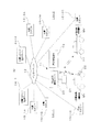
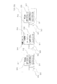
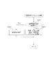
図1は、車両運行管理システムの概要構成ブロック図である。
充電配車スケジュール管理システム10は、大別すると、複数の業務車両MV(例えば、タクシー)の充電配車を行う充電配車管理システム11と、充電配車管理システム11と接続され、オペレータにより運行スケジュール、業務車両の充電配車以外の配車(業務配車)の管理および乗務員の勤務スケジュール管理などの運行スケジュール管理を行う運行管理端末13と、充電配車管理システム11とインターネット12を含む通信ネットワークを介して接続された複数の充電スタンド管理システム14−1、14−2と、を備えている。
Next, preferred embodiments of the present invention will be described with reference to the drawings.
FIG. 1 is a schematic configuration block diagram of a vehicle operation management system.
The charge dispatching
充電配車管理システム11は、複数の充電スタンド管理システム14−1、14−2と連携して、各充電スタンド管理システム14−1、14−2のそれぞれの管理下にある充電スタンドへ自己が管理している業務車両MVを向かわせて、当該充電スタンドにおいて、充電を行うように充電配車を管理している。この場合において、充電スタンドにおいて充電する車両の充電以外の他の運行にできる限り影響を与えないような時間帯に充電を行えるように充電スタンド管理システム14−1、14−2と調整を図って運行管理を行っている。
The charge
充電配車管理システム11は、大別すると、無線通信装置21及びインターネット12に接続されるとともに、充電配車スケジュールの管理を行う充電配車管理サーバ23と、を備えている。
この場合に、無線通信装置21は、無線通信機能を有する業務車両MVに搭載された車載機器22と無線通信を行って、充電配車スケジュールを車載機器22に通知したり、業務車両MVに対し、運行管理端末13から充電配車管理サーバ23を介して入力される乗務配車スケジュールを受信して、乗務員に乗務配車先の情報(地図、名称等)を通知したりする。
一方、車載機器22は、図示しないGPSレシーバにより取得した自車両位置に基づいて業務車両MVの実際の運行状況を表す運行状況データを、無線通信装置21を介して、充電配車管理サーバ23あるいは運行管理端末13に通知する。
The charging vehicle
In this case, the
On the other hand, the in-
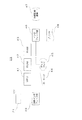
図2は、充電配車管理サーバの概要構成ブロック図である。
充電配車管理サーバ23は、パーソナルコンピュータと同様に構成されており、充電配車管理サーバ23を中枢的に制御するMPU41と、MPU41が動作するためのプログラムなどを記憶しているROM42と、各種データを一時的に記憶するワークテーブルとしてのRAM43と、データ入力などを行うためのキーボード44と、各種情報を表示するディスプレイ45と、各種外部機器との間のインタフェース動作を行うインタフェース部46と、後述する各種データベースなどのデータを記憶するハードディスクドライブ装置などの外部記憶装置47と、各種情報をプリントアウトするプリンタ48と、無線通信装置21及びインターネット12に所定の通信プロトコルで接続される通信インタフェース部49と、を備えている。
FIG. 2 is a schematic configuration block diagram of the charge dispatch management server.
The charge
ここで、外部記憶装置47に記憶されている各種データベースについて説明する。
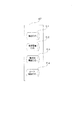
図3は、データベースの説明図である。
外部記憶装置47に記憶されているデータベースとしては、運行管理端末13から取得した乗務員に関する情報および乗務スケジュール、車両の運行状況などを記憶する乗務データベース(DB)51と、車両毎の単位バッテリ容量あたりの走行可能距離(電費)を記憶する車両電費データベース(DB)52と、乗務員毎の単位バッテリ容量あたりの走行可能距離(電費)を記憶する乗務員電費データベース(DB)53と、設定された走行ルートにおいて消費バッテリ容量を算出するための各種情報が格納されたルート情報データベース(DB)54と、が記憶されている。
ここで、ルート情報データベース54としては、例えば、途中に交叉点などの分岐点を含まず、その両端が分岐点である道路、あるいは、途中に交叉点などの分岐点を含まず、その一端が分岐点であり、他端が行き止まりである道路である単位道路毎、かつ、積載重量(乗員を含む)、時間帯(昼間、夜間等)、季節(エアコンの利用の有無など)、天候(ワイパーの使用の有無など)毎に消費バッテリ容量を記憶している。
この場合において、一の単位道路について、平地に設けられた道路のように、第1の方向(例えば、上り方向)に車両を走行させた場合と、第2の方向(例えば、下り方向)に車両を走行させた場合とで、消費バッテリ容量に実質的な差がない場合には、消費バッテリ容量を当該単位道路について一組記憶しているが、山間路や坂などのように走行方向で大きく消費バッテリ容量が変わる場合には、走行方向に応じて二組の消費バッテリ容量を記憶している。
Here, various databases stored in the
FIG. 3 is an explanatory diagram of the database.
The database stored in the
Here, for example, the
In this case, for one unit road, the vehicle travels in the first direction (for example, the upward direction) and the second direction (for example, the downward direction), like a road provided on a flat ground. When there is no substantial difference in battery consumption capacity when the vehicle is driven, a set of battery consumption capacity is stored for the unit road, but in the driving direction such as mountain roads and slopes. When the consumed battery capacity changes greatly, two sets of consumed battery capacity are stored according to the traveling direction.
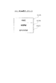
図4は、乗務データベースのデータフォーマットの説明図である。
乗務データベース51は、乗務員名あるいは乗務員名に対応する乗務員コードを格納した乗務員名テーブル51A、乗務スケジュールの基本パターンを格納した基本乗務スケジュールテーブル51B、乗務スケジュールの基本パターンをモディファイした乗務スケジュールを格納した乗務スケジュールテーブル51Cと、配車情報を含む車両の運行状況を随時格納する運行状況テーブル51Dと、を備えている。
FIG. 4 is an explanatory diagram of the data format of the crew database.
The
図5は、車両電費データベースのデータフォーマットの説明図である。
車両電費データベース52は、車種名あるいは車種に対応する車種コードを格納した車種名テーブル52Aと、単位バッテリ容量あたりの走行可能距離(電費)を道路の種類(一般道路あるいは高速道路)、道路の状態(平坦路、下り坂、上り坂、山間路など)、車両状態(エアコン使用の有無、ヘッドライト点灯の有無、ワイパー使用の有無、CDプレーヤなどの車載アクセサリ機器の使用の有無)、積載重量(乗員を含む)、時間帯(渋滞時間帯、バス優先レーン設定時間帯、特定道路の通行禁止時間帯など)、などの走行条件に対応づけて格納した車両電費テーブル52Bと、満充電時に走行可能な最大巡航距離を格納した最大巡航距離テーブル53と、を備えている。
FIG. 5 is an explanatory diagram of a data format of the vehicle electricity cost database.
The vehicle
図6は、乗務員電費データベースのデータフォーマットの説明図である。
乗務員電費データベース53は、乗務員名あるいは乗務員名に対応する乗務員コードを格納した乗務員名テーブル53Aと、当該乗務員における単位バッテリ容量あたりの走行可能距離(電費)を道路の種類(一般道路あるいは高速道路)、道路の状態(平坦路、下り坂、上り坂、山間路など)、車両状態(エアコン使用の有無、ワイパー使用の有無、CDプレーヤなどの車載アクセサリ機器の使用の有無)などの走行条件に対応づけて格納した乗務員電費テーブル53Bと、を備えている。
FIG. 6 is an explanatory diagram of the data format of the crew power cost database.
The crew
図7は、ルート情報データベースのデータフォーマットの説明図である。
ルート情報データベース54は、道路をノード及びリンクで表した場合に、ノードを特定するノード特定テーブル54Aと、道路の種類(一般道路あるいは高速道路)あるいは道路の状態(平坦路、下り坂、上り坂、山間路など)を格納するルート情報テーブル54Bと、を備えている。
この場合において、ルート情報テーブル54Bは、同一のリンク(道路あるいは経路)であっても、車両の進行方向により電費が異なるような条件下(例えば、同一の坂を登っている場合と、下っている場合等)においては、進行方向毎に道路の状態に対応するルート情報を格納している。すなわち、二つのノードNA、NB間を結ぶリンクに対して、車両がノードNAからノードNBに向かう場合と、車両がノードNBからノードNAに向かう場合とで、異なるルート情報を格納している。
FIG. 7 is an explanatory diagram of the data format of the route information database.
The
In this case, the route information table 54B has the same link (road or route) under the condition that the electricity cost varies depending on the traveling direction of the vehicle (for example, when climbing the same slope, In the case where the vehicle is present, the route information corresponding to the road condition is stored for each traveling direction. That is, different route information is stored for a link connecting two nodes NA and NB depending on whether the vehicle goes from node NA to node NB or a vehicle goes from node NB to node NA.
次に、充電スタンド管理システムについて説明する。
充電スタンド管理システム14−1は、図1に示すように、充電スタンド管理サーバ24−1と、充電スタンド管理サーバ24−1とインターネット12を介して接続され、充電スタンド管理サーバ24−1の管理下で実際の充電を行う充電スタンド15−1A〜15−1Cを備えている。
同様に、充電スタンド管理システム14−2は、充電スタンド管理サーバ24−2と、充電スタンド管理サーバ24−2とインターネット12を介して接続され、充電スタンド管理サーバ24−2の管理下で実際の充電を行う充電スタンド15−2A〜15−2Cを備えている。
Next, the charging station management system will be described.
As shown in FIG. 1, the charging station management system 14-1 is connected to the charging station management server 24-1, the charging station management server 24-1 via the
Similarly, the charging station management system 14-2 is connected to the charging station management server 24-2, the charging station management server 24-2, and the
図8は、充電スタンドの概要構成ブロック図である。
ここで、充電スタンド15−1A〜15−1C、15−2A〜15−2Cは、同一構成であるので、充電スタンド15−1Aを例として説明する。
充電スタンド15−1Aは、充電時に電気車両(主として動力用バッテリ)に接続されて電力を供給する複数台の充電コネクタ(給電コネクタ)30を有するとともに、コントローラ31、操作パネル32およびディスプレイ33を内蔵した充電器34を一または複数(図8の例では3台)備えている。
ここで、充電コネクタ30としては、ロックアーム、ロックレバー、リリースレバーなどのロック機構付きの銃型コネクタや、家庭用コンセント用コネクタに近い形状を有するコネクタなどの複数種類が存在する。
FIG. 8 is a schematic configuration block diagram of the charging station.
Here, since the charging stands 15-1A to 15-1C and 15-2A to 15-2C have the same configuration, the charging stand 15-1A will be described as an example.
The charging stand 15-1A includes a plurality of charging connectors (power supply connectors) 30 that are connected to an electric vehicle (mainly a power battery) and supply power during charging, and incorporate a
Here, as the charging
コントローラ31は、通信インタフェースを有するマイクロコンピュータとして構成されており、インターネット12を介した通信を行う通信機能と、充電開始タイミング、充電終了タイミング、充電電力量あるいは充電器の故障状態を検出する状態検出機能と、充電時のユーザ認証を行うユーザ認証機能と、を備え、状態検出機能により検出した状態およびユーザ認証機能により得られたユーザ認証情報を通信機能により充電スタンド管理サーバ24−1、24−2に通知することとなっている。
ここで、状態検出機能は、充電コネクタ30の接続状態、図示しない電力量計の計測状態あるいは充電器34の各部に設けられた図示しない各種センサ(電圧センサ、電流センサ、短絡センサなど)による検出状態に基づいて実現される。
また、ユーザ認証機能は、非接触型ICカードや携帯電話端末の通信機能などを用いて得られたユーザ認証情報(例えば、電話回線網から送られる電話番号情報、ユーザが入力したパスワード情報など)を用いて実現される。
The
Here, the state detection function is detected by a connection state of the charging
The user authentication function includes user authentication information obtained by using a communication function of a non-contact type IC card or a mobile phone terminal (for example, telephone number information sent from a telephone line network, password information input by a user, etc.) It is realized using.
図9は、充電スタンド管理サーバの概要構成ブロック図である。
ここで、充電スタンド管理サーバ24−1、24−2は、同一構成であるので、充電スタンド管理サーバ24−1を例として説明する。
充電スタンド管理サーバ24−1は、図9に示すように、ユーザ情報を格納したユーザデータベース(DB)35、課金情報を格納した課金データベース(DB)36、充電スタンド15−1A〜15−1C、15−2A〜15−2Cの各ユーザの利用に関するデータを格納した利用データベース(DB)37、充電スタンド15−1A〜15−1C、15−2A〜15−2Cの管理を行う充電スタンド管理処理部38および充電スタンド情報表示処理を行う充電スタンド情報表示処理部39を備えており、各部はバスにより接続されている。
FIG. 9 is a schematic configuration block diagram of the charging station management server.
Here, since the charging stand management servers 24-1 and 24-2 have the same configuration, the charging stand management server 24-1 will be described as an example.
As shown in FIG. 9, the charging station management server 24-1 includes a user database (DB) 35 storing user information, a charging database (DB) 36 storing charging information, charging stations 15-1A to 15-1C, Charging station management processing unit for managing the usage database (DB) 37, charging stations 15-1A to 15-1C, and 15-2A to 15-2C, which stores data relating to the usage of each user 15-2A to 15-
図10は、ユーザデータベースのデータフォーマットの説明図である。
ユーザデータベース35は、充電スタンド15−1A〜15−1C、15−2A〜15−2Cを利用するユーザ(個人あるいは法人)に関する情報が格納されており、ユーザを特定するためのユーザIDデータが格納されたユーザIDテーブル35Aと、ユーザ認証を行うための認証情報データが格納された認証情報テーブル35Bと、ユーザの車種に基づいて充電対象のバッテリ、バッテリの充電方法(充電電圧、充電電流、充電方式など)を特定するための車種データが格納された車種テーブル35Cと、過去の充電履歴を表す充電履歴データが格納された充電履歴テーブル35Dと、を備えている。
FIG. 10 is an explanatory diagram of the data format of the user database.
The
ここで、充電履歴テーブル35Dは、充電開始時のバッテリの残存容量を表す初期残存量データが格納された初期残容量テーブル、充電に要した時間を表す充電時間データが格納された充電時間テーブル、充電を行った日付を表す充電日データが格納された充電日データテーブル及び充電開始時刻を表す充電開始時刻データが格納された充電開始時刻テーブルを備えている。
この場合において、初期残存量データとしては、バッテリの初期電圧などが用いられる。また、充電時間データに代えて、充電完了時刻データを記憶することにより、充電開始時刻データおよび充電完了時刻データに基づいて充電時間をその都度算出するようにしても良い。
Here, the charging history table 35D includes an initial remaining capacity table in which initial remaining amount data representing the remaining capacity of the battery at the start of charging is stored, a charging time table in which charging time data representing the time required for charging is stored, A charging date data table storing charging date data representing a date of charging and a charging start time table storing charging start time data representing a charging start time are provided.
In this case, an initial voltage of the battery is used as the initial remaining amount data. Further, by storing the charging completion time data instead of the charging time data, the charging time may be calculated each time based on the charging start time data and the charging completion time data.
図11は、課金データベースのデータフォーマットの説明図である。
本実施形態においては、充電料金の徴収を銀行口座からの引き落とし、クレジットカードによる決済、請求書の発行に伴う銀行振り込みなどにより課金を行っており、課金データを収集する必要があるので、充電スタンド管理サーバ24−1においては、課金データベース36を構築している。
課金データベース36は、ユーザを特定するためのユーザIDデータが格納されたユーザIDテーブル36A、充電スタンド15−1A〜15−1Cを利用した日時を表す利用日時データが格納された利用日時テーブル36B、利用した充電スタンド15−1A〜15−1Cを特定するための利用充電スタンドデータが格納された利用充電スタンドテーブル36C、課金データが格納された課金テーブル36Dと、を備えている。
FIG. 11 is an explanatory diagram of the data format of the accounting database.
In the present embodiment, the charging fee is collected from the bank account, the payment is made by credit card, the bank transfer accompanying the issuance of the invoice, and it is necessary to collect the charging data. In the management server 24-1, a charging
The charging
ここで、課金テーブル36Dには、充電に利用した電力量を表す利用電力量データが格納された利用電力量フィールド36D1と、利用時点における電力単価を表す電力単価データが格納された電力単価フィールド36D2と、利用電力量と電力単価との積の値となる利用料データが格納された利用料フィールド36D3と、当該ユーザの課金区分データが格納された課金区分フィールド36D4と、を備えている。
ここで、電力単価が時期により異なる場合には、利用電力量フィールド36D1に格納される利用電力量データおよび電力単価フィールド36D2に格納される電力単価データは、時期毎に区別して複数格納される。
なお、引き落とし口座などの実際の課金に必要な情報については、従前と同様の方法により、別途保持している。
したがって、利用料フィールド36D3に格納された利用量データに基づいて課金額を算出して引き落としなどを行うとともに、各ユーザに対し毎月利用報告書兼請求書を郵送し、あるいは図示しないインターネットのサイトにおいて各ユーザがアクセス可能な状態で公開するようになっている。
Here, in the charging table 36D, a used power amount field 36D1 storing used power amount data representing the amount of power used for charging, and a power unit price field 36D2 storing power unit price data representing the power unit price at the time of use. And a usage fee field 36D3 that stores usage fee data that is the product of the amount of power used and the unit price of electric power, and a charging category field 36D4 that stores the charging category data of the user.
Here, when the power unit price varies depending on the time, a plurality of pieces of used power amount data stored in the used power amount field 36D1 and power unit price data stored in the power unit price field 36D2 are stored separately for each time period.
Information necessary for actual billing such as a debit account is separately held in the same manner as before.
Accordingly, the billing amount is calculated based on the usage amount data stored in the usage fee field 36D3 and deducted, etc., and a monthly usage report / invoice is mailed to each user, or at an Internet site (not shown). It is open to the public so that each user can access it.
図12は、利用データベースのデータフォーマットの説明図である。
利用データベース37は、複数のデータベースから構成されており、充電スタンドの所在地、充電器の設置台数、営業時間、営業日などのスタンド情報および充電スタンド毎(さらには、充電器毎)の充電配車スケジュールが格納されたスタンド情報データベース(DB)37Aと、車種毎の1回の充電に要した充電平均時間が、一日の時間帯毎、曜日毎、月毎、季節毎等に格納された車種充電情報データベース(DB)37Bと、各充電スタンドの時間帯毎の充電平均時間等の時間帯利用情報が格納された時間帯利用統計データベース(DB)37Cと、登録ユーザの利用状況の統計データを格納した利用統計データベース37Dと、を備えている。
FIG. 12 is an explanatory diagram of the data format of the usage database.
The
ここで、利用統計データベース37Dには、各登録ユーザについて、一日の時間帯毎、曜日毎、月毎、季節毎、充電スタンド毎等の充電平均時間のデータ(平均時間および標準偏差)が格納されており、予測充電時間が充電平均時間よりも大幅にずれる場合には、充電平均時間に近づくように補正を行い、更新するようにしている。
Here, the
図13は、車載機器の概要構成ブロック図である。
次に車載機器22の構成について説明する。
車載機器22は、GPS衛星からの測位用電波を受信して自車両位置を検出するGPSユニット22Aと、無線通信装置21との間で通信を行う無線通信ユニット22Bと、ドライバーである乗務員が各種操作を行うための操作部22Cと、音声による無線通信を行うためのハンディマイク22Dと、ナビゲーション画面、充電配車時刻や充電スタンド情報等の各種情報を表示するためのディスプレイ22Eと、車載バッテリBTの残容量を検出する容量検出部22Fを備え、車載装置全体を中枢的に制御するコントローラ22Gと、を備えている。
ここで、容量検出部22Fは、車載バッテリBTの電圧に基づいて、残容量を検出している。
FIG. 13 is a schematic configuration block diagram of the in-vehicle device.
Next, the configuration of the in-
The in-
Here, the
次に、充電配車管理サーバにおける充電配車管理処理について説明する。
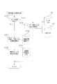
図14は、充電配車管理処理のフローチャートである。
まず、充電配車管理処理の概要的な流れを説明する。
充電配車管理処理において、まず充電配車管理サーバ23は、運行管理端末13が運行管理を行っている全ての業務車両MVについての充電配車スケジュールを作成する(ステップS11)。
Next, the charge dispatch management process in the charge dispatch management server will be described.
FIG. 14 is a flowchart of the charge dispatch management process.
First, a general flow of the charge allocation management process will be described.
In the charge dispatch management process, the charge
次に運行管理端末13において、配車受付を行ったか否かを判別する(ステップS12)。
ステップS12の判別において、配車受付を行っていない場合には(ステップS12;No)、待機状態となる。
ステップS12の判別において、配車受付が行われた場合には(ステップS12;Yes)、配車に伴う業務車両MVの運行により予定していた充電配車の時間帯に充電を行えなくなるなどの状況が発生した場合など必要に応じて充電配車スケジュールを更新する(ステップS13)。
Next, in the
If it is determined in step S12 that the vehicle dispatch is not accepted (step S12; No), a standby state is entered.
In the determination of step S12, if a vehicle allocation is accepted (step S12; Yes), a situation occurs in which charging cannot be performed during the scheduled time of charging vehicle allocation due to the operation of the business vehicle MV accompanying the vehicle allocation. If necessary, the charge dispatch schedule is updated (step S13).
続いて、充電配車管理サーバ23は、業務車両MVの実際の運行状況において、バッテリ残量の低下や、遠距離配車予定などが発生して、充電配車スケジュールの変更が必要となったか否かを判別する(ステップS14)。
ステップS14の判別において、充電配車スケジュールの変更が必要でない場合には(ステップS14;No)、再び処理をステップS12に移行して、以下同様の処理を行う。
一方、ステップS14の判別において、充電配車スケジュールの変更が必要となった場合には(ステップS14;Yes)、充電配車スケジュールを変更し(ステップS15)、変更後、再び処理をステップS12に移行して、以下同様の処理を行う。
これらの結果、本実施形態によれば、業務車両の運行をできる限り妨げることなく、充電を行うことができる。
Subsequently, the charging
If it is not necessary to change the charge dispatch schedule in step S14 (step S14; No), the process proceeds to step S12 again, and the same process is performed.
On the other hand, if it is necessary to change the charge dispatch schedule in step S14 (step S14; Yes), the charge dispatch schedule is changed (step S15). After the change, the process proceeds to step S12 again. Thereafter, the same processing is performed.
As a result, according to the present embodiment, charging can be performed without hindering the operation of the business vehicle as much as possible.
以下、充電配車管理処理の詳細について説明する。
図15は、充電配車スケジュール作成処理のフローチャートである。
充電配車管理処理のステップS11における充電配車スケジュール作成処理においては、充電配車管理サーバ23は、運行管理端末13から当日の乗務スケジュールを取得して乗務DB51に格納する(ステップS21)。
続いて、充電配車管理サーバ23は、取得した乗務スケジュールに基づいて、乗務員の勤務予定、車両状況(運行中、点検中等)に応じた、運行の空き時間や、乗務員の休憩時間を考慮して充電配車スケジュールを作成する(ステップS22)。
Hereinafter, details of the charge allocation management process will be described.
FIG. 15 is a flowchart of a charge dispatch schedule creation process.
In the charge dispatch schedule creation process in step S11 of the charge dispatch management process, the charge
Subsequently, the charging
具体的には、当日の乗務スケジュールを参照し、充電スタンド管理サーバ24−1、24−2に問い合わせを行い、可能な限り各業務車両MVの乗務員が休憩をとるであろうと予測される時間帯に充電が行えるように、充電スタンド管理サーバ24−1、24−2に対して充電予約を行って、充電配車スケジュールを作成することとなる。 Specifically, referring to the current day's crew schedule, the charging station management servers 24-1 and 24-2 are inquired, and the time zone in which the crew of each business vehicle MV is expected to take a break as much as possible. In order to perform charging, a charging reservation is made to the charging station management servers 24-1 and 24-2, and a charging dispatch schedule is created.
図16は、充電配車スケジュール設定処理のフローチャートである。
まず、充電配車管理サーバ23は、無線通信装置21を介して業務車両MVの車載機器22からバッテリ残容量及び位置情報を取得する(ステップS31)。
次に取得したバッテリ残容量に基づいて走行可能距離を算出する(ステップS32)。
FIG. 16 is a flowchart of the charge dispatch schedule setting process.
First, the charge
Next, a travelable distance is calculated based on the acquired remaining battery capacity (step S32).
図17は、走行可能距離算出処理の処理フローチャートである。
まず、充電配車管理サーバ23は、車両電費データベース52を参照して、当該業務車両の単位バッテリ容量あたりの走行可能距離(電費)を道路の種類(一般道路あるいは高速道路)、道路の状態(平坦路、下り坂、上り坂、山間路など)、車両状態(エアコン使用の有無、ワイパー使用の有無、CDプレーヤなどの車載アクセサリ機器の使用の有無)などの走行条件に対応づけて格納した車両電費テーブル52Bを読み出す(ステップS41)。
FIG. 17 is a process flowchart of a travelable distance calculation process.
First, the charge
続いて充電配車管理サーバ23は、乗務員電費データベース53を参照して、当該乗務員における単位バッテリ容量あたりの走行可能距離(電費)を道路の種類(一般道路あるいは高速道路)、道路の状態(平坦路、下り坂、上り坂、山間路など)、車両状態(エアコン使用の有無、ワイパー使用の有無、CDプレーヤなどの車載アクセサリ機器の使用の有無)などの走行条件に対応づけて格納した乗務員電費テーブル53Bを読み出す(ステップS42)。
続いて充電配車管理サーバ23は、ルート情報DB54を参照して通常業務における平均的な道路条件を含む平均走行ルートを適宜設定し、車両電費テーブル52Bのデータおよび乗務員電費テーブル53Bのデータを参酌して当該ルートの電費を算出する(ステップS43)。すなわち、業務車両MVに当該乗務員が搭乗した場合の平均電費を算出することとなる。
Subsequently, the charge
Subsequently, the charging
これにより、現在の電池残量から、平均走行ルートを走行した場合の走行可能距離を算出し(ステップS44)、処理をステップS33(図16参照)に移行する。
続いて充電配車管理サーバ23は、乗務員であるドライバーの勤務時間を取得する(ステップS33)。
次に充電配車管理サーバ23は、全車両MVについて走行可能距離の算出および乗務員勤務時間の取得処理が完了したか否かを判別する(ステップS33)。
ステップS33の判別において、いまだ全車両MVについて走行可能距離の算出および乗務員勤務時間の取得処理が完了していない場合には(ステップS33;No)、再び処理をステップS31に移行し、以下同様の処理を全車両MVについて走行可能距離の算出および乗務員勤務時間の取得処理が完了するまで繰り返す。
Thus, the travelable distance when traveling on the average travel route is calculated from the current remaining battery level (step S44), and the process proceeds to step S33 (see FIG. 16).
Subsequently, the charging
Next, the charge
If it is determined in step S33 that the calculation of the travelable distance and the crew member working time acquisition process have not yet been completed for all the vehicles MV (step S33; No), the process proceeds to step S31 again, and so on. The process is repeated until the calculation of the travelable distance and the crew member working time acquisition process are completed for all the vehicles MV.
一方、ステップS33の判別において、全業務車両MVについて走行可能距離の算出および乗務員勤務時間の取得処理が完了した場合には(ステップS33;Yes)、全業務車両について、いずれの業務車両が優先して充電を行わなければならないかを表す充電優先順位を算出する(ステップS35)。
この充電優先順位は、よりバッテリ残容量が少ない業務車両MV、より長距離走行の必要がある業務車両MVが優先され、同一のバッテリ残容量あるいは走行予定距離の業務車両である場合には、積載人員あるいは積載貨物量がより多いと想定される業務車両MVが優先され、エアコンやワイパーの利用が想定される地域に向かうと想定される業務車両MVが優先されて、これらの業務車両MVの充電優先順位が高く設定されることとなる。
そして、充電配車管理サーバは、充電優先順位の高い業務車両を優先して、充電スタンドの予約を行うこととなる(ステップS36)。
On the other hand, in the determination of step S33, when the calculation of the travelable distance and the crew member working time acquisition process are completed for all the business vehicles MV (step S33; Yes), which business vehicle has priority for all the business vehicles. The charging priority order indicating whether or not charging should be performed is calculated (step S35).
This charging priority is given to priority when the business vehicle MV with a smaller remaining battery capacity and the business vehicle MV that needs to travel a longer distance are prioritized, and the business vehicles have the same remaining battery capacity or planned travel distance. Priority is given to business vehicles MV that are assumed to have more personnel or loaded cargo, and priority is given to business vehicles MV that are supposed to go to areas where air conditioners and wipers are expected to be used, and charging these business vehicles MV. The priority is set higher.
Then, the charging dispatch management server gives priority to the business vehicle having a high charging priority and reserves the charging station (step S36).
ここで、充電スタンドの予約処理について説明する。
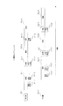
図18は、充電予約のシーケンスフローチャートである。
図18においては、充電配車管理サーバ23が、充電スタンド管理サーバ24−1に対して充電予約を行う場合を例として説明する。
まず、充電配車管理サーバ23は、インターネット12を介して充電スタンド管埋サーバ24−1にログイン要求を行う(ステップS51)。
Here, the charging station reservation process will be described.
FIG. 18 is a sequence flowchart of a charge reservation.
In FIG. 18, the case where the charge
First, the charge
この場合において、ログイン要求は、予め発行されたユーザIDを用いる。ここで、充電スタンド管埋サーバ24−1側では、ユーザIDの他、充電配車管理サーバ23の電子署名などを用いてユーザ認証のための情報としている。
ログインが完了すると、充電スタンド管埋サーバ24−1は、ログイン完了応答を行い(ステップS52)。
これにより、充電配車管理サーバ23は、予約設定処理を行う(ステップS53)。
具体的には、充電配車管理サーバ23は、各業務車両MVのバッテリ残容量が必要以上に低下する前に充電が行えるように、ステップS35において算出した充電優先順位が高い順に早い時間に充電予約ができるように予約設定処理を行う。
In this case, the login request uses a previously issued user ID. Here, on the charging stand embedding server 24-1 side, the user ID is used as information for user authentication by using the electronic signature of the charging
When the login is completed, the charging stand embedding server 24-1 makes a login completion response (step S52).
Thereby, the charge
Specifically, the charge
すなわち、予約設定処理においては、予約を希望する充電スタンド(あるいは充電スタンド群)、予約希望日時(時間帯)、予約対象の車両を特定する情報、充電時間、業務車両数などが設定される。この場合において、充電スタンドの指定は、第1希望充電スタンド、第2希望充電スタンドのように複数の希望を複数の地域にわたるものとしたりすることも可能である。 That is, in the reservation setting process, a charging station (or charging station group) desired to be reserved, a reservation desired date and time (time zone), information for specifying a reservation target vehicle, a charging time, the number of business vehicles, and the like are set. In this case, the designation of the charging station can be performed over a plurality of areas such as the first desired charging station and the second desired charging station.
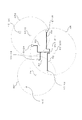
図19は、充電スタンドの指定の説明図である。
充電配車管理サーバ23が配置されている営業所60において業務車両MVを運行させる業務エリアをARとし、充電スタンド管理サーバ24−1の管理下にある充電スタンド15−1A〜15−1C及び充電スタンド管理サーバ24−2の管理下にある充電スタンド15−2A〜15−2Cのうち、充電スタンド15−2A、15−2Bが業務エリアAR内に位置したとする場合には、充電配車管理サーバ23は、充電対象の業務車両MVが営業所60に位置している場合には、営業所60から充電スタンド15−1Aまでの道程R1、充電スタンド15−1Bまでの道程R2、充電スタンド15−2Aまでの道程R3、充電スタンド15−2Bまでの道程R4を比較し、例えば、
R1<R3<R4<R2
である場合には、第1希望充電スタンドを充電スタンド15−1Aとし、第2希望充電スタンドを充電スタンド15−2Aとする。
FIG. 19 is an explanatory diagram of designation of a charging station.
Charging stations 15-1A to 15-1C and charging stations under the management of the charging station management server 24-1 are designated AR as a business area where the business vehicle MV is operated at the
R1 <R3 <R4 <R2
The first desired charging station is the charging station 15-1A, and the second desired charging station is the charging station 15-2A.
この場合に原則的には、充電配車管理サーバ23は、業務エリアをAR内で充電可能な充電スタンドを探すこととなるが、業務エリアをAR内で電可能な充電スタンドが充電時間帯などの観点から見つからない場合には、できる限り現在の業務車両MVの位置に近い充電スタンドを既望充電スタンドに設定することとなる。
また、予約対象の車両を特定する情報については、全ての業務車両MVで共通とすることも可能である。これにより、充電予約後に実際に予約した充電スタンドへ向かう業務車両MVを充電配車管理サーバ23側で容易に変更することが可能となる。
In this case, in principle, the charge
Further, the information specifying the reservation target vehicle can be shared by all the business vehicles MV. As a result, it is possible to easily change the business vehicle MV heading for the charging station actually reserved after the charging reservation on the charging
そして、この予約設定処理により、予約要求内容が確定し、受付要求が充電スタンド管埋サーバ24−1側に送信されることとなる(ステップS54)。
これにより、充電スタンド管理サーバ24は、予約処理に処理を移行する(ステップS55)。
Then, the reservation request content is confirmed by this reservation setting process, and the acceptance request is transmitted to the charging stand embedding server 24-1 side (step S54).
Thereby, the charging station management server 24 shifts the processing to the reservation processing (step S55).
図20は、充電スタンド管理サーバの予約処理の処理フローチャートである。
予約要求を受信した充電スタンド管理サーバ24−1は、当該予約要求に対応する予約対象の充電スタンド14−1A〜14−1C(あるいは、当該充電スタンド14−1A〜14−1Cの充電器34毎)の充電スタンドスケジュールを対応するスタンド情報データベースから取得する(ステップS61)。
続いて充電スタンド管理サーバ24−1は、取得した予約対象の充電スタンド14−1A〜14−1Cの充電スタンドスケジュールに基づいて、予約希望日時以前に予約があるか否かを判別する(ステップS62)。
FIG. 20 is a process flowchart of the reservation process of the charging station management server.
Receiving the reservation request, the charging station management server 24-1 sets the charging stations 14-1A to 14-1C to be reserved corresponding to the reservation request (or the
Subsequently, the charging station management server 24-1 determines whether or not there is a reservation before the reservation desired date / time based on the acquired charging station schedules of the charging stations 14-1A to 14-1C to be reserved (step S62). ).
ステップS62の判別において、予約がある場合には(ステップS62;Yes)、当該予約要求に対応する予約について充電配車管理サーバ23が充電時間を指定しているか否かを判別する(ステップS63)。
ステップS33の判別において、充電配車管理サーバ23が充電時間を指定している場合には(ステップS63;Yes)、処理をステップS65に移行する。
ステップS63の判別において、充電配車管理サーバ23が充電時間を指定していない場合には(ステップS63;No)、予測充電時間を算出する予測充電時間算出処理を行う(ステップS64)。
If it is determined in step S62 that there is a reservation (step S62; Yes), it is determined whether or not the charging
If it is determined in step S33 that the charging
If it is determined in step S63 that the charging
ここで、予測充電時間算出処理について説明する。
図21は、予測充電時間算出処理の処理フローチャートである。
まず、充電スタンド管理サーバ24−1は、ユーザ登録がある充電配車管理サーバ23の予約であるか否かを判別する(ステップS75)。
ステップS75の判別において、当該充電配車管理サーバ23のユーザ登録がなされている場合には(ステップS75;Yes)、予約対象の車両を特定する情報に基づく車種による充電時間算出を行う(ステップS76)。
具体的には、充電スタンド管理サーバ24−1は、予め記憶していたユーザデータベースを参照して、充電配車管理サーバ23が予約して充電しようとしている車両に搭載されている車載バッテリの容量、種別、個数などを把握する。
これらの情報は、通常、車種(グレード、仕様)が定まれば、搭載しているバッテリの容量、種別、個数は定まるため、車種により判断することとなる。
Here, the predicted charging time calculation process will be described.
FIG. 21 is a process flowchart of the predicted charging time calculation process.
First, the charging station management server 24-1 determines whether or not it is a reservation for the charging
If it is determined in step S75 that the user registration of the charge
Specifically, the charging station management server 24-1 refers to a user database stored in advance, and the capacity of the in-vehicle battery mounted on the vehicle that the charging
Normally, when the vehicle type (grade, specification) is determined, the capacity, type, and number of the mounted batteries are determined based on the vehicle type.
ところで、車載バッテリの充電に要する時間は、バッテリの充電状態、劣化度合いによって大きく異なることが知られている。例えば、経年劣化によれば、10年で容量が70%程度となってしまうため、充電に要する時間が大きく変動することとなる。また、バッテリの実容量(残容量)が大きければ、充電時間が比較的短くなり、バッテリの実容量(残容量)が小さければ、充電時間が比較的長くなる。
そこで、本実施形態においては、当該登録ユーザにおける充電対象の車両の過去の充電スタンド利用時の充電状況を統計的に処理して得られる利用統計データを格納した利用データベースを参照して車種による判断を補正することとしている。例えば、上述した経年劣化を考慮する場合には、バッテリ容量の移動平均値を用いて充電に要する時間を補正することとなる。
By the way, it is known that the time required for charging the in-vehicle battery varies greatly depending on the state of charge of the battery and the degree of deterioration. For example, according to aging degradation, the capacity will be about 70% in 10 years, so the time required for charging will vary greatly. Further, if the actual capacity (remaining capacity) of the battery is large, the charging time is relatively short, and if the actual capacity (remaining capacity) of the battery is small, the charging time is relatively long.
Therefore, in the present embodiment, determination by vehicle type with reference to a usage database that stores usage statistical data obtained by statistically processing the charging status of the vehicle to be charged in the past when the charging user has been used by the registered user. Is going to be corrected. For example, when considering the above-mentioned aging deterioration, the time required for charging is corrected using the moving average value of the battery capacity.
また、充電対象の車両すなわち、ユーザによっては、バッテリ充電を行う状況(バッテリの充電状態、曜日、時間帯、季節、天気)などにある程度傾向がみられ、その時々の実際の充電時間と、予測充電時間との差である予測誤差の傾向が見いだされるので、利用統計データを利用して予測充電時間をより正確に算出することが可能となる。
具体的には、当該登録ユーザの当該時期(時間帯、曜日、季節、天気)における予測バッテリ残量を求め、当該登録ユーザの車種により指定される充電方法(充電電流、充電電圧などの設定に基づく充電パターン〉で充電した場合の充電予測時間を算出する。
In addition, depending on the vehicle to be charged, that is, depending on the user, there is a tendency to some extent in the state of battery charging (battery charging state, day of the week, time zone, season, weather, etc.). Since a tendency of a prediction error that is a difference from the charging time is found, it is possible to calculate the predicted charging time more accurately using the usage statistical data.
Specifically, the estimated battery remaining amount at the time (time zone, day of the week, season, weather) of the registered user is obtained, and the charging method (charging current, charging voltage, etc.) designated by the registered user's vehicle type is set. Based on charging pattern>, the estimated charging time is calculated.
まず、時間帯について説明すると、通常利用する時間帯に要する充電時問と、通常利用しない時間帯に要する充電時間とは、異なる傾向がある。
これは、通常利用する時間帯は、余裕を持って充電を行っていると考えることができ、その電池残量もほぼ同様の傾向を示すと考えられるからである。
First, the time zone will be described. There is a tendency that the charging time required in the normally used time zone and the charging time required in the normally unused time zone are different.
This is because it can be considered that charging is performed with a margin during normal use, and the remaining battery level is considered to exhibit a similar tendency.
同様に曜日についても、ある程度傾向が見られるので、例えば、土日などの渋滞が発生する可能性が高い曜日においては、消費電力量が増加し、予測充電時間が長くなるとして、例えば、5%増しとする。
また、時間帯については、夜間になればヘッドライトを含むライトを点灯させ、あるいは、渋滞時間帯などでは、消費電力量が増加し、予測充電時間が長くなるとして、例えば、5%増しとする。
また、季節については、電気車両の場合、エアコン(クーラー、ヒーター)等を利用する季節においては、通常よりも電力の消費が大きくなるため、充電頻度は高くなっているにも関わらず、充電時の電池残量もエアコンなどを利用しない場合と比較して電池残量が少なくなっている等の傾向を示す可能性が高く、これらの傾向を反映して充電時間を予測する必要があるからである。より詳細には、冬期はヒーターを使用しているので電池残量が少なくなり、予測充電時間が長くなるとして、例えば、20%増しとし、夏季はクーラーを使用しているので池残量が少なくなり、予測充電時間が長くなるとして、例えば、10%増しとする。
Similarly, since there is a certain tendency for the days of the week, for example, on days of the week when there is a high possibility of traffic jams such as Saturdays and Sundays, the amount of power consumption increases and the estimated charging time becomes longer. And
In addition, regarding the time zone, lights such as headlights are turned on at night, or the amount of power consumption is increased and the estimated charging time is increased in a traffic time zone, for example, an increase of 5%. .
In addition, in the case of electric vehicles, in the season of using an air conditioner (cooler, heater), etc., power consumption is higher than usual. It is highly possible that the remaining battery level of the battery is likely to show a tendency that the remaining battery level is low compared to when not using an air conditioner, etc., and it is necessary to predict the charging time reflecting these trends is there. More specifically, since the heater is used in winter, the remaining battery level is low, and the estimated charging time is increased. For example, it is increased by 20%, and the cooler is used in summer, so the remaining battery level is low. Assuming that the estimated charging time becomes longer, for example, it is assumed that the estimated charging time is increased by 10%.
また、天気については、雨などの場合にはワイパーを駆動する必要があるので、予測充電時間が長くなるとして、例えば、5%増しとする。
したがって、時間帯、曜日、季節等に基づいて利用統計データを取得しておくことで、より正確な充電時間を予測することが可能となるのである。
In addition, regarding the weather, since it is necessary to drive the wiper in the case of rain or the like, it is assumed that the estimated charging time becomes longer, for example, an increase of 5%.
Therefore, it is possible to predict a more accurate charging time by acquiring usage statistics data based on the time zone, day of the week, season, and the like.
一方、ステップS75の判別において、ユーザ登録がなされていない場合、例えば、新規のユーザには(ステップS75:No)、車種充電情報データベース37Bを参照して車種・仕様、充電スタンドの所在地、設置されている充電器の種類などに基づく充電時間算出(充電時間推定)を行う(ステップS77)。
具体的には、車種・仕様に基づいて対象となる車両に搭載されているバッテリの個数、容量、種類が定まるとともに、使用年数等の推定が可能であるので、当該バッテリの標準的な充電時間を算出する。そして、充電スタンドの所在地および設置されている充電器の種類に基づいて算出した充電時間を補正する。
On the other hand, if the user is not registered in the determination in step S75, for example, for a new user (step S75: No), the vehicle type / specification, the location of the charging station, and the location of the charging station are installed with reference to the vehicle type charging
Specifically, the number, capacity, and type of batteries installed in the target vehicle are determined based on the vehicle type and specifications, and the estimated years of use can be estimated. Is calculated. Then, the charging time calculated based on the location of the charging stand and the type of the installed charger is corrected.
すなわち、バッテリの個数、容量、種類に基づいて、標準充電時間を車種充電情報データベース37Bを参照して求め、推定した使用年数に基づいた劣化を考慮し、さらに充電スタンドの所在地および設置されている充電器の種類に基づいて予測される充電時間を算出することとなる。
この場合において、車種・仕様のみしか分からない場合等には、予め記憶していた車種から定まる標準充電時間を用いて、充電時間の算出に代える。
続いて充電スタンド管理サーバ24−1は、ステップS77において算出した充電時間を時間帯別の平均充電時間を考慮して補正して、より正確な充電予測時間を算出し(ステップS78)、処理をステップS65に移行する。
That is, based on the number, capacity, and type of the battery, the standard charging time is obtained by referring to the vehicle type charging
In this case, when only the vehicle type / specification is known, the standard charging time determined from the previously stored vehicle type is used instead of calculating the charging time.
Subsequently, the charging station management server 24-1 corrects the charging time calculated in step S77 in consideration of the average charging time for each time zone, calculates a more accurate estimated charging time (step S78), and performs processing. Control goes to step S65.
充電スタンド管理サーバ24−1は、全予約について処埋が終了したか否かを判別する(ステップS65)。
ステップS65の判別において、全予約について処理が終了していない場合には(ステップS65;No)、充電スタンド管理サーバ24−1は、処理を再びステップS63に移行して以下同様の処理を行い、充電時間が指定されていない全ての予約について予測充電時間の算出処理(ステップS64)を行うこととなる。
The charging station management server 24-1 determines whether or not processing has been completed for all reservations (step S65).
If it is determined in step S65 that the processing has not been completed for all reservations (step S65; No), the charging station management server 24-1 proceeds to step S63 again and performs the same processing. The calculation process (step S64) of the predicted charging time is performed for all reservations for which the charging time is not specified.
ステップS62の判別において予約がない場合(ステップS62;No)、あるいはステップS65の判別において全予約について予測充電時間算出処理が終了した場合には(ステップS65;Yes)、充電スタンド管理サーバ24−1は、取得した予約対象の充電スタンド14−1A〜14−1Cの充電スタンドスケジュールに基づいて、予約希望日時として指定された予約希望日に、充電順番待ちを行っている待ちユーザがいるか否かを判別する(ステップS66)。なお、実際には、予約希望日が当日である場合にだけ、充電順番待ちを行っているユーザが存在するはずであるので、予約希望日が当日以外の場合には、充電順番待ちを行っているユーザは存在せず、常にステップS66の判別は、「No」となる。 When there is no reservation in the determination in step S62 (step S62; No), or when the predicted charging time calculation process is completed for all reservations in the determination in step S65 (step S65; Yes), the charging station management server 24-1. Indicates whether there is a waiting user who is waiting for the charging turn on the reservation desired date designated as the reservation desired date and time based on the acquired charging station schedules of the charging target 14-1A to 14-1C. It discriminate | determines (step S66). Actually, there should be a user who is waiting for the charging order only when the desired reservation date is the same day. Therefore, if the desired reservation date is other than the current day, the user waits for the charging order. No user is present, and the determination in step S66 is always “No”.
ステップS65の判別において、充電順番待ちユーザがいる場合には(ステップS66;Yes)、当該充電順番待ちユーザが所望の充電時間を指定しているか否かを判別する(ステップS67)。
ステップS67の判別において、充電順番待ちユーザが所望の充電時間を指定している場合には(ステップS67;Yes)、処理をステップS69に移行する。
ステップS67の判別において、充電順番待ちユーザが所望の充電時間を指定していない場合には(ステップS67;No)、当該充電順番待ちユーザについて予測充電時間を算出する予測充電時間算出処理を行う(ステップS68)。
If it is determined in step S65 that there is a user waiting for the charging order (step S66; Yes), it is determined whether the user waiting for the charging order specifies a desired charging time (step S67).
If it is determined in step S67 that the user waiting for charging has designated a desired charging time (step S67; Yes), the process proceeds to step S69.
If it is determined in step S67 that the user waiting for the charging order has not designated the desired charging time (step S67; No), a predicted charging time calculation process is performed for calculating the predicted charging time for the user waiting for the charging order ( Step S68).
続いて充電スタンド管理サーバ24−1は、全ての充電順番待ちユーザについて処理が終了したか否かを判別する(ステップS69)。
ステップS69の判別において、全ての充電順番待ちユーザについて処理が終了していない場合には(ステップS69;No)、充電スタンド管理サーバ24−1は、処埋を再びステップS67に移行して以下同様の処理を行い、充電順番待ちユーザにより所望の充電時間が指定されていない全ての充電順番待ちユーザについて予測充電時間の算出処理(ステップS68)を行うこととなる。
ステップS66の判別において充電順番待ちユーザがいない場合(ステップS66;No)、あるいはステップS69の判別において全充電順番待ちユーザについて予測充電時間算出処理が終了した場合には(ステップS69;Yes),充電スタンド管埋サーバ24−1は、後述する受付結果を通知するための予約受付処理を行う(ステップS70)。
Subsequently, the charging station management server 24-1 determines whether or not the processing has been completed for all the users waiting for charging (step S69).
If it is determined in step S69 that the process has not been completed for all the users waiting for charging (step S69; No), the charging station management server 24-1 proceeds to step S67 again, and so on. This process is performed, and the calculation process of the predicted charging time (step S68) is performed for all the users waiting for the charging order for which the desired charging time is not specified by the user waiting for the charging order.
If there is no user waiting for the charging order in the determination in step S66 (step S66; No), or if the predicted charging time calculation process is completed for all users waiting for the charging order in the determination in step S69 (step S69; Yes), charging is performed. The stand embedding server 24-1 performs a reservation acceptance process for notifying the acceptance result described later (step S70).
これにより予約申込内容が確定し、充電スタンド管理サーバ24−1は、予約スケジュールを記憶しておくスタンド情報データベースにおける予約対象の充電スタンド14−1A〜14−1Cの充電スタンドスケジュールを更新して(ステップS71)、予約処理(ステップS55)を終了する。 As a result, the reservation application content is confirmed, and the charging station management server 24-1 updates the charging station schedules of the charging stations 14-1A to 14-1C to be reserved in the station information database storing the reservation schedule ( Step S71) and the reservation process (Step S55) are terminated.
続いて、充電スタンド管理サーバ24−1は、充電配車管理サーバ23に対して予約を受け付けた旨及び充電スタンド予約情報を通知する受付結果通知処理を行う(ステップS56)。
これにより充電配車管理サーバ23は、受付結果通知に基づいて、受付結果画面表示を行い(ステップS57)、取得した充電スタンド予約情報を充電配車スケジュールとして組み込むこととなる(ステップS58)。
Subsequently, the charging station management server 24-1 performs a reception result notification process for notifying the charging vehicle
Thereby, the charge
図22は、充電配車スケジュールの作成例の説明図である。
図22においては、第1の乗務員DR1および第2の乗務員DR2の運行スケジュール(乗務配車スケジュール)を示している。
乗務員DR1の運行スケジュールにおいては、第1の乗務時間帯W11の後に、休憩時間帯R11を挟んで第2の乗務時間帯W12が配されている。さらに第2の乗務時間帯W12の後に、休憩時間帯R12を挟んで第3の乗務時間帯W13が配されている。
そして、現時点では、第1の乗務時間帯W11中に乗務配車予定D11、D12、…が組み込まれている。ここで、乗務配車予定とは、顧客からの配車依頼の電話による配車の予定等の突発的な配車予定や、介護施設への送り迎えなどの定期的に組み込まれた配車予定などが含まれる。
さらに休憩時間帯R11には、第1の充電配車スケジュールC11が組み込まれ、休憩時間帯R12には、第2の充電配車スケジュールC12が組み込まれている。
FIG. 22 is an explanatory diagram of an example of creating a charge dispatch schedule.
In FIG. 22, the operation schedule (crew dispatch schedule) of 1st crew member DR1 and 2nd crew member DR2 is shown.
In the operation schedule of the crew member DR1, the second crew time zone W12 is arranged after the first crew time zone W11 with the break time zone R11 interposed therebetween. Further, after the second crew time zone W12, a third crew time zone W13 is arranged across the break time zone R12.
And at present, crew dispatch schedules D11, D12,... Are incorporated in the first crew time zone W11. Here, the crew dispatch schedule includes an unexpected dispatch schedule such as a schedule for dispatch by telephone of a request for dispatch from a customer, and a regularly scheduled dispatch schedule such as a pick-up to a care facility.
Further, the first charging dispatch schedule C11 is incorporated in the break time zone R11, and the second charging dispatch schedule C12 is incorporated in the break time zone R12.
乗務員DR1の運行スケジュールにおいては、第1の乗務時間帯W11の後に、休憩R11を挟んで第2の乗務時間帯W12が配されている。さらに第2の乗務時間帯W12の後に、休憩R12を挟んで第3の乗務時間帯W13が配されている。
そして、現時点では、第1の乗務時間帯W11中に配車予定D11、D12、…が組み込まれている。
さらに休憩時間帯R11には、第1の充電配車スケジュールC11が組み込まれ、休憩時間帯R12には、第2の充電配車スケジュールC12が組み込まれている。
In the flight schedule of the crew member DR1, the second crew time zone W12 is arranged after the first crew time zone W11 with the break R11 in between. Further, after the second crew time zone W12, a third crew time zone W13 is arranged with a break R12 in between.
At the present time, the dispatch schedules D11, D12,... Are incorporated in the first crew time zone W11.
Further, the first charging dispatch schedule C11 is incorporated in the break time zone R11, and the second charging dispatch schedule C12 is incorporated in the break time zone R12.
同様に、乗務員DR2の運行スケジュールにおいては、第1の乗務時間帯W21の後に、休憩R21を挟んで第2の乗務時間帯W22が配されている。さらに第2の乗務時間帯W22の後に、休憩R22を挟んで第3の乗務時間帯W23が配されている。
そして、現時点では、第1の乗務時間帯W21中に乗務配車予定D21、D22、…が組み込まれ、休憩時間帯R21には、第1の充電配車スケジュールC21が組み込まれ、休憩時間帯R22には、第2の充電配車スケジュールC22が組み込まれている。
これらの場合において、充電配車スケジュールC11、C12を乗務員DR1の休憩R11、R12に相当する時間帯に組み込むようにし、充電配車スケジュールC21、C22を乗務員DR2の休憩R21、R22に相当する時間帯に組み込むようにしているのは、車両の運用(運行)効率を向上させるためである。
Similarly, in the operation schedule of the crew member DR2, the second crew time zone W22 is arranged after the first crew time zone W21 across the break R21. Further, after the second crew time zone W22, a third crew time zone W23 is arranged with a break R22 in between.
At the present time, the crew dispatch schedules D21, D22,... Are incorporated in the first crew time zone W21, the first charging dispatch schedule C21 is incorporated in the break time zone R21, and the break time zone R22 A second charge dispatch schedule C22 is incorporated.
In these cases, the charging dispatch schedules C11 and C12 are incorporated in the time zone corresponding to the breaks R11 and R12 of the crew DR1, and the charging dispatch schedules C21 and C22 are incorporated in the time slots corresponding to the breaks R21 and R22 of the crew DR2. The reason for this is to improve the operation (operation) efficiency of the vehicle.
続いて、再び図14の処理に移行し、インターネット12を介した配車依頼あるいは電話を受けたオペレータの手入力による配車受付がなされたか否かを判別する(ステップS12)。
ステップS12の判別において、配車受付がなされていない場合には(ステップS12;No)、待機状態となる。
ステップS12の判別において、配車受付がなされた場合には(ステップS12;Yes)、現時点における乗務予定及び充電予定に基づいて必要に応じて充電配車スケジュールを更新し、充電配車スケジュールを当該配車受付に対応する配車予定に影響のない時間帯に変更する(ステップS13)。
Subsequently, the process again proceeds to the process of FIG. 14, and it is determined whether or not a vehicle allocation request has been made by a vehicle allocation request via the
In the determination in step S12, if the vehicle dispatch is not accepted (step S12; No), the standby state is entered.
In the determination of step S12, if the vehicle allocation is accepted (step S12; Yes), the charging vehicle allocation schedule is updated as necessary based on the current crew schedule and the charging schedule, and the charging vehicle allocation schedule is set as the vehicle allocation acceptance. The time is changed so as not to affect the corresponding dispatch schedule (step S13).
図23は、充電配車スケジュール更新処理の処理フローチャートである。
ここで、充電配車スケジュールの変更処理をより具体的に説明する。
まず、充電配車管理サーバ23は、既に充電スタンド管理サーバ24−1、24−2に対して予約を入れてある充電予約のうち、当該業務車両以外の他の業務車両に対応する充電予約であって、当該車両に対する充電予約に対応車両を変更可能な他の充電予約があるか否かを判別する(ステップS81)。
ステップS81の判別において、変更可能な他の充電予約がない場合には(ステップS81;No)、充電スタンド管理サーバ24−1、24−2に対して新規に充電予約処理を行う(ステップS82)。
FIG. 23 is a process flowchart of the charge dispatch schedule update process.
Here, the charging dispatch schedule changing process will be described more specifically.
First, the charge
If it is determined in step S81 that there is no other charge reservation that can be changed (step S81; No), a new charge reservation process is performed on the charging station management servers 24-1 and 24-2 (step S82). .
ステップS81の判別において、既に充電スタンド管理サーバに対して予約を入れてある充電予約のうち、当該車両以外の他の車両に対応する充電予約であって、当該車両に対する充電予約に対応車両を変更可能な他の充電予約がある場合には、充電予約の変更処理(対応車両の変更、あるいは対応乗務員の認証手続きの変更など)を行うとともに、自己で管理している乗務スケジュール及び充電配車スケジュールの変更処理を行う(ステップS83)。
続いて、充電配車管理サーバ23は、バッテリ残量低下や遠距離の乗務配車予定などにより充電配車スケジュールの変更が必要か否かを判別する(ステップS14)。
ステップS14の判別により充電配車スケジュールの変更が必要ない場合には(ステップS14;No)、処理を再びステップS12に移行し、以下、同様の処理を行う。
In the determination of step S81, among the charge reservations that have already been reserved with respect to the charge stand management server, the charge reservation corresponds to a vehicle other than the vehicle, and the vehicle corresponding to the charge reservation for the vehicle is changed. If there are other possible charge reservations, the charge reservation change process (change of the corresponding vehicle or change of the authentication procedure of the corresponding crew member, etc.) is performed, and the self-managed crew schedule and charge dispatch schedule A change process is performed (step S83).
Subsequently, the charge
If it is not determined in step S14 that the charge dispatch schedule needs to be changed (step S14; No), the process proceeds to step S12 again, and the same process is performed thereafter.
図24は、充電配車スケジュールの変更処理の説明図である。
ここで、充電配車スケジュールの変更処理についてより具体的に説明する。
この場合において、初期状態においては、図23の上段に示すように、休憩時間帯R11には、第1の充電配車スケジュールC11が組み込まれ、休憩時間帯R12には、第2の充電配車スケジュールC12が組み込まれているものとする。
ここで、第2の乗務員DR2の運行スケジュールの第1の乗務時間帯W21の時刻t1において、充電が必要と判断される状況となった場合には、充電配車管理サーバ23は、既に充電スタンド管理サーバ24−1に対して予約を入れてある充電予約のうち、当該車両(一の車両)以外の他の車両に対応する充電予約であって、当該車両に対する充電予約に対応車両を変更可能な他の充電予約があるか否かを判別する(ステップS81)こととなる。
FIG. 24 is an explanatory diagram of a charging dispatch schedule change process.
Here, the charging dispatch schedule changing process will be described more specifically.
In this case, in the initial state, as shown in the upper part of FIG. 23, the first charging dispatch schedule C11 is incorporated in the break time zone R11, and the second charging dispatch schedule C12 is built in the break time zone R12. Is incorporated.
Here, in the situation where it is determined that charging is necessary at the time t1 of the first crew time zone W21 of the operation schedule of the second crew member DR2, the charging
この場合には、当該車両以外の他の車両に対応する充電予約であって、当該車両に対する充電予約に対応車両を変更可能な他の充電予約として乗務員DR1の乗務する車両の充電配車スケジュールC11(時刻t2)が存在している。そして、乗務員DR1の乗務する車両のバッテリの残容量は、多少充電配車スケジュールを変更しても問題がない容量となっているものとする。
したがって、充電配車管理サーバ23は、充電配車スケジュールC11を第2の乗務員DR2の運行スケジュールのうち休憩時間帯R21に変更する。
In this case, it is a charge reservation corresponding to a vehicle other than the vehicle, and the charge allocation schedule C11 of the vehicle on which the crew DR1 is occupying as another charge reservation capable of changing the vehicle corresponding to the charge reservation for the vehicle. Time t2) exists. The remaining battery capacity of the vehicle on which the crew member DR1 is riding is assumed to be a capacity that does not cause a problem even if the charging dispatch schedule is slightly changed.
Therefore, the charge
これにより、第1の乗務員DR1の休憩時間帯R11を第2の乗務員DR2の運行スケジュールにおける充電配車スケジュールC21に対応する時間帯に変更し、時刻t3における充電配車スケジュールC21を第1の乗務員DR1の運行スケジュールのうち休憩時間帯R11を休憩時間帯R11’に変更する。
この結果、時刻t4における元の充電配車スケジュールC12についても、充電の必要がなくなった場合には、当該充電配車スケジュールC12をキャンセルし、その旨を充電スタンド管理サーバ24−1に通知することとなる。
As a result, the break time zone R11 of the first crew member DR1 is changed to a time zone corresponding to the charge dispatch schedule C21 in the operation schedule of the second crew member DR2, and the charge dispatch schedule C21 at time t3 is changed to that of the first crew member DR1. In the operation schedule, the break time zone R11 is changed to the break time zone R11 ′.
As a result, when charging is no longer necessary for the original charging dispatch schedule C12 at time t4, the charging dispatch schedule C12 is canceled and the charging station management server 24-1 is notified of the cancellation. .
以上の説明のように、既に充電スタンド管理サーバ24−1に対して予約を入れてある充電予約のうち、当該車両以外の他の車両に対応する充電予約であって、当該車両に対する充電予約に対応車両を変更可能な他の充電予約がある場合には、それらを相互に変更することにより、新たに充電予約を行うことなく、充電配車スケジュールを融通し合って、効率的な充電が行えることとなる。
この場合においては、充電予約を行った車両と実際に充電を行う車両とは異なることとなるため、充電スタンド14−1A〜14−Cにおいて、実際に充電を行う場合の認証が問題なく行えるように、各業務車両MVを特定する情報を統一しておく必要がある。
As described above, among the charging reservations that have already been reserved for the charging station management server 24-1, the charging reservation is for a vehicle other than the vehicle, and for the charging reservation for the vehicle. If there are other charge reservations that can change the corresponding vehicle, they can be changed mutually so that the charge dispatch schedule can be interchanged and efficient charging can be performed without making a new charge reservation. It becomes.
In this case, since the vehicle that has made the charge reservation is different from the vehicle that actually performs the charge, the charging stand 14-1A to 14-C can be authenticated without any problem when actually charging. In addition, it is necessary to unify information for specifying each business vehicle MV.
図25は、充電配車スケジュールの変更処理[新規予約]の説明図である。
この場合において、初期状態においては、図23の上段に示すように、乗務員DR1の休憩時間帯R12には、充電配車スケジュールC11が組み込まれているものとする。
ここで、乗務員DR1の運行スケジュールにおいて、第1の乗務時間帯W11において、充電が必要と判断される状況となった場合には、充電配車管理サーバ23は、既に充電スタンド管理サーバ24−1に対して予約を入れてある充電予約のうち、当該車両以外の他の車両に対応する充電予約であって、当該車両に対する充電予約に対応車両を変更可能な他の充電予約があるか否かを判別する(ステップS81)こととなるが、この場合には、当該車両以外の他の車両に対応する充電予約が存在しないので、充電配車管理サーバ23は、新たに時刻t12に充電予約を行うとともに、当該時刻t12に設定されていた休憩時間帯R11を休憩時間帯R13に変更し、当該休憩時間帯R13新たな充電配車スケジュールC13が含まれるようにする。
FIG. 25 is an explanatory diagram of a charge dispatch schedule change process [new reservation].
In this case, in the initial state, as shown in the upper part of FIG. 23, the charging dispatch schedule C11 is incorporated in the break time zone R12 of the crew DR1.
Here, in the operation schedule of the crew member DR1, when it is determined that charging is necessary in the first crew time zone W11, the charge
この結果、時刻t13に設定されていた元の充電配車スケジュールC11についてはキャンセルし、その旨を充電スタンド管理サーバ24−1に通知することとなる。
以上の説明のように、既に充電スタンド管理サーバ24−1に対して予約を入れてある充電予約のうち、当該車両以外の他の車両に対応する充電予約であって、当該車両に対する充電予約に対応車両を変更可能な他の充電予約がない場合には、新規に充電予約を行い、既に存在する充電予約については、キャンセルすることにより、車両の運行に影響を与えることなく充電が行えることとなる。
As a result, the original charge dispatch schedule C11 set at time t13 is canceled, and a notification to that effect is sent to the charging station management server 24-1.
As described above, among the charging reservations that have already been reserved for the charging station management server 24-1, the charging reservation is for a vehicle other than the vehicle, and for the charging reservation for the vehicle. If there is no other charge reservation that can change the corresponding vehicle, make a new charge reservation and cancel the existing charge reservation so that it can be charged without affecting the operation of the vehicle. Become.
以上の説明のように、本実施形態によれば、複数の車両の運行管理を行う場合であっても、運行管理への影響を低減して、充電配車スケジュールを管理することができる。
したがって、待ち時間の少ない充電を行うことができるとともに、充電期間中あるいは充電切れによる営業機会損失を低減することができる。
また、電気車両(電気自動車)ではなく、プラグインハイブリッド車両に適用する場合には、ガソリンよりも安価な電力で走行できる機会を増加させることが可能となり、運行コストを低減することが可能となる。
以上の説明においては、充電配車管理サーバ23と、運行管理端末13とは、別体に設けていたが、充電配車管理サーバ23に運行管理機能を搭載するように構成することも可能である。
以上の説明においては、運行管理端末13は、直接インターネット12に接続されていなかったが、タクシーの配車申込をインターネット12を介してユーザが直接行えるように構成することも可能である。
以上の説明においては、タクシー業者において、運行管理下にある業務用車両の充電配車スケジュールの管理について説明したが、同様にレンタカー業者、カーシェアリング業者、バス業者、トラックなどの車両を用いた運送業者についても、運行管理下にある業務用車両の充電配車スケジュールの管理を行うように構成することも可能である。
また、タクシー業者、レンタカー業者に適用する場合においては、予め観光モデルコースを提供することにより、タクシーを利用しているユーザあるいは車両をレンタルしたユーザが車両を降りて観光している時間帯に充電配車スケジュールを設定することにより、これらのユーザに充電に要する時間をあまり意識させないように構成することも可能である。
As described above, according to the present embodiment, even when the operation management of a plurality of vehicles is performed, the influence on the operation management can be reduced and the charge dispatch schedule can be managed.
Therefore, it is possible to perform charging with a short waiting time, and it is possible to reduce a business opportunity loss during the charging period or due to the charge being exhausted.
Moreover, when applied to a plug-in hybrid vehicle instead of an electric vehicle (electric vehicle), it is possible to increase the chance of traveling with electric power cheaper than gasoline, and to reduce operation costs. .
In the above description, the charging vehicle
In the above description, the
In the above explanation, the taxi dealer explained the management of the charging and dispatch schedule of commercial vehicles under operation management, but in the same way, car rental dealers, car sharing dealers, bus dealers, trucks using vehicles such as trucks In addition, it is also possible to configure so as to manage the charge dispatch schedule of business vehicles under operation management.
In addition, when applying to a taxi dealer or a rental car dealer, by providing a sightseeing model course in advance, charging is performed during the time when a user who uses a taxi or a user who rents a vehicle gets off the vehicle and is sightseeing By setting a vehicle allocation schedule, it is possible to make these users less aware of the time required for charging.
10 充電配車スケジュール管理システム
11 充電配車管理システム
12 インターネット(通信ネットワーク)
13 運行管理端末
14−1、14−2 充電スタンド管理システム
15−1A〜15−1C 充電スタンド
15−2A〜15−2C 充電スタンド
21 無線通信装置
22 車載機器
23 充電配車管理サーバ
24−1、24−2 充電スタンド管理サーバ
41 MPU(制御装置)
AR 業務エリア
10 Charging and dispatching
13 Operation Management Terminals 14-1 and 14-2 Charging Station Management Systems 15-1A to 15-1C Charging Stations 15-2A to 15-
AR business area
Claims (4)
前記制御装置は、前記バッテリの容量の消費予定を、季節、天気あるいは時間帯の走行条件、前記車両の装置構成、当該車両の乗務員あるいは走行ルートに基づいて算出する、
ことを特徴とする充電配車管理サーバ。 For a plurality of vehicles each equipped with a vehicle driving battery, charging is performed by designating a charging station and a time zone to be charged based on the remaining capacity of the battery for each vehicle and the planned consumption of the capacity of the battery. A control device for setting a charge dispatch schedule for instructing a dispatch for
The control device calculates the battery capacity consumption schedule based on driving conditions of the season, weather or time zone, the device configuration of the vehicle, the crew of the vehicle or the driving route,
The charge dispatch management server characterized by the above.
前記充電スタンドは、充電スタンド管理サーバにより管理されており、
前記制御装置は、前記充電スタンド管理サーバに対応する充電スタンドの利用状況を前記充電スタンド管理サーバに通信ネットワークを介して問い合わせ、充電を行うべき充電スタンド及び時間帯を指定する、
ことを特徴とする充電配車管理サーバ。 In the charge dispatch management server according to claim 1,
The charging station is managed by a charging station management server,
The control device inquires the charging station management server about the usage status of the charging station corresponding to the charging station management server via a communication network, and specifies a charging station and a time zone to be charged.
The charge dispatch management server characterized by the above.
前記制御装置は、前記車両が搭載している車載装置に対し、無線通信ネットワークを介して、充電配車スケジュールを通知することを特徴とする充電配車管理サーバ。 In the charge dispatch management server according to claim 1 or 2,
The control device notifies the on-board device mounted on the vehicle of a charge / allocation schedule via a wireless communication network.
前記充電スタンドを管理する充電スタンド管理サーバと、
前記充電スタンド管理サーバと通信ネットワークを介して接続され、前記電気車両を前記充電スタンドへ充電のために配車する配車指示を行う充電配車管理サーバと、を備え、
前記充電配車管理サーバは、車両駆動用のバッテリをそれぞれ搭載した複数の電気車両について、前記電気車両毎の前記バッテリの残容量及び当該バッテリの容量の消費予定に基づいて、充電を行うべき充電スタンド及び時間帯を指定して充電のための配車を指示する充電配車スケジュールを設定し、前記バッテリの容量の消費予定を、季節、天気あるいは時間帯の走行条件、前記車両の装置構成、当該車両の乗務員あるいは走行ルートに基づいて算出する制御装置を備えた、
ことを特徴とする充電配車管理システム。 A plurality of charging stands having a battery charger for charging a battery for driving the electric vehicle;
A charging station management server for managing the charging station;
A charging dispatch management server that is connected to the charging station management server via a communication network, and that gives a dispatch instruction for dispatching the electric vehicle to the charging station for charging;
The charging allocation management server is configured to charge a plurality of electric vehicles each equipped with a vehicle driving battery based on a remaining capacity of the battery for each electric vehicle and a consumption schedule of the capacity of the battery. And setting a charging dispatch schedule for instructing dispatching for charging by designating a time zone, and consuming schedule of the capacity of the battery according to season, weather or time zone driving conditions, device configuration of the vehicle, With a control device that calculates based on the crew or travel route,
Charging dispatch management system characterized by that.
Priority Applications (2)
| Application Number | Priority Date | Filing Date | Title |
|---|---|---|---|
| JP2010125281A JP5607427B2 (en) | 2010-05-31 | 2010-05-31 | Charging vehicle allocation management server and charging vehicle allocation management system |
| US13/118,649 US20110246252A1 (en) | 2010-03-31 | 2011-05-31 | Vehicle charging allocation managing server and vehicle charging allocation managing system |
Applications Claiming Priority (1)
| Application Number | Priority Date | Filing Date | Title |
|---|---|---|---|
| JP2010125281A JP5607427B2 (en) | 2010-05-31 | 2010-05-31 | Charging vehicle allocation management server and charging vehicle allocation management system |
Publications (2)
| Publication Number | Publication Date |
|---|---|
| JP2011253257A JP2011253257A (en) | 2011-12-15 |
| JP5607427B2 true JP5607427B2 (en) | 2014-10-15 |
Family
ID=44710710
Family Applications (1)
| Application Number | Title | Priority Date | Filing Date |
|---|---|---|---|
| JP2010125281A Active JP5607427B2 (en) | 2010-03-31 | 2010-05-31 | Charging vehicle allocation management server and charging vehicle allocation management system |
Country Status (2)
| Country | Link |
|---|---|
| US (1) | US20110246252A1 (en) |
| JP (1) | JP5607427B2 (en) |
Families Citing this family (176)
| Publication number | Priority date | Publication date | Assignee | Title |
|---|---|---|---|---|
| JP2012073979A (en) * | 2010-09-30 | 2012-04-12 | Hitachi Automotive Systems Ltd | Ev vehicle dispatch and operation management system |
| US8799037B2 (en) | 2010-10-14 | 2014-08-05 | Palto Alto Research Center Incorporated | Computer-implemented system and method for managing motor vehicle parking reservations |
| US8730062B2 (en) | 2010-10-14 | 2014-05-20 | Xerox Corporation | Computer-implemented system and method for providing gun shot detection through a centralized parking services server |
| US9082112B2 (en) | 2010-12-15 | 2015-07-14 | Symbotic, LLC | Autonomous transport vehicle charging system |
| US20120233077A1 (en) * | 2011-03-07 | 2012-09-13 | GM Global Technology Operations LLC | Electric charging station reservation system and method |
| US9288270B1 (en) | 2011-04-22 | 2016-03-15 | Angel A. Penilla | Systems for learning user preferences and generating recommendations to make settings at connected vehicles and interfacing with cloud systems |
| US9581997B1 (en) | 2011-04-22 | 2017-02-28 | Angel A. Penilla | Method and system for cloud-based communication for automatic driverless movement |
| US9648107B1 (en) | 2011-04-22 | 2017-05-09 | Angel A. Penilla | Methods and cloud systems for using connected object state data for informing and alerting connected vehicle drivers of state changes |
| US9285944B1 (en) | 2011-04-22 | 2016-03-15 | Angel A. Penilla | Methods and systems for defining custom vehicle user interface configurations and cloud services for managing applications for the user interface and learned setting functions |
| US9139091B1 (en) | 2011-04-22 | 2015-09-22 | Angel A. Penilla | Methods and systems for setting and/or assigning advisor accounts to entities for specific vehicle aspects and cloud management of advisor accounts |
| US10824330B2 (en) | 2011-04-22 | 2020-11-03 | Emerging Automotive, Llc | Methods and systems for vehicle display data integration with mobile device data |
| US9963145B2 (en) | 2012-04-22 | 2018-05-08 | Emerging Automotive, Llc | Connected vehicle communication with processing alerts related to traffic lights and cloud systems |
| US9365188B1 (en) | 2011-04-22 | 2016-06-14 | Angel A. Penilla | Methods and systems for using cloud services to assign e-keys to access vehicles |
| US9809196B1 (en) | 2011-04-22 | 2017-11-07 | Emerging Automotive, Llc | Methods and systems for vehicle security and remote access and safety control interfaces and notifications |
| US11132650B2 (en) | 2011-04-22 | 2021-09-28 | Emerging Automotive, Llc | Communication APIs for remote monitoring and control of vehicle systems |
| US11270699B2 (en) | 2011-04-22 | 2022-03-08 | Emerging Automotive, Llc | Methods and vehicles for capturing emotion of a human driver and customizing vehicle response |
| US9189900B1 (en) | 2011-04-22 | 2015-11-17 | Angel A. Penilla | Methods and systems for assigning e-keys to users to access and drive vehicles |
| US11203355B2 (en) | 2011-04-22 | 2021-12-21 | Emerging Automotive, Llc | Vehicle mode for restricted operation and cloud data monitoring |
| US9171268B1 (en) | 2011-04-22 | 2015-10-27 | Angel A. Penilla | Methods and systems for setting and transferring user profiles to vehicles and temporary sharing of user profiles to shared-use vehicles |
| US9230440B1 (en) | 2011-04-22 | 2016-01-05 | Angel A. Penilla | Methods and systems for locating public parking and receiving security ratings for parking locations and generating notifications to vehicle user accounts regarding alerts and cloud access to security information |
| US10286919B2 (en) | 2011-04-22 | 2019-05-14 | Emerging Automotive, Llc | Valet mode for restricted operation of a vehicle and cloud access of a history of use made during valet mode use |
| US11370313B2 (en) | 2011-04-25 | 2022-06-28 | Emerging Automotive, Llc | Methods and systems for electric vehicle (EV) charge units and systems for processing connections to charge units |
| US9346365B1 (en) | 2011-04-22 | 2016-05-24 | Angel A. Penilla | Methods and systems for electric vehicle (EV) charging, charging unit (CU) interfaces, auxiliary batteries, and remote access and user notifications |
| US9697503B1 (en) | 2011-04-22 | 2017-07-04 | Angel A. Penilla | Methods and systems for providing recommendations to vehicle users to handle alerts associated with the vehicle and a bidding market place for handling alerts/service of the vehicle |
| US9493130B2 (en) | 2011-04-22 | 2016-11-15 | Angel A. Penilla | Methods and systems for communicating content to connected vehicle users based detected tone/mood in voice input |
| US9104537B1 (en) | 2011-04-22 | 2015-08-11 | Angel A. Penilla | Methods and systems for generating setting recommendation to user accounts for registered vehicles via cloud systems and remotely applying settings |
| US9229905B1 (en) | 2011-04-22 | 2016-01-05 | Angel A. Penilla | Methods and systems for defining vehicle user profiles and managing user profiles via cloud systems and applying learned settings to user profiles |
| US10572123B2 (en) | 2011-04-22 | 2020-02-25 | Emerging Automotive, Llc | Vehicle passenger controls via mobile devices |
| US9371007B1 (en) | 2011-04-22 | 2016-06-21 | Angel A. Penilla | Methods and systems for automatic electric vehicle identification and charging via wireless charging pads |
| US12337716B2 (en) | 2011-04-22 | 2025-06-24 | Emerging Automotive, Llc | Systems for transferring user profiles between vehicles using cloud services |
| US9123035B2 (en) | 2011-04-22 | 2015-09-01 | Angel A. Penilla | Electric vehicle (EV) range extending charge systems, distributed networks of charge kiosks, and charge locating mobile apps |
| US9818088B2 (en) | 2011-04-22 | 2017-11-14 | Emerging Automotive, Llc | Vehicles and cloud systems for providing recommendations to vehicle users to handle alerts associated with the vehicle |
| US11294551B2 (en) | 2011-04-22 | 2022-04-05 | Emerging Automotive, Llc | Vehicle passenger controls via mobile devices |
| US9348492B1 (en) | 2011-04-22 | 2016-05-24 | Angel A. Penilla | Methods and systems for providing access to specific vehicle controls, functions, environment and applications to guests/passengers via personal mobile devices |
| US10217160B2 (en) | 2012-04-22 | 2019-02-26 | Emerging Automotive, Llc | Methods and systems for processing charge availability and route paths for obtaining charge for electric vehicles |
| US9215274B2 (en) | 2011-04-22 | 2015-12-15 | Angel A. Penilla | Methods and systems for generating recommendations to make settings at vehicles via cloud systems |
| US10289288B2 (en) | 2011-04-22 | 2019-05-14 | Emerging Automotive, Llc | Vehicle systems for providing access to vehicle controls, functions, environment and applications to guests/passengers via mobile devices |
| US9536197B1 (en) | 2011-04-22 | 2017-01-03 | Angel A. Penilla | Methods and systems for processing data streams from data producing objects of vehicle and home entities and generating recommendations and settings |
| US9180783B1 (en) | 2011-04-22 | 2015-11-10 | Penilla Angel A | Methods and systems for electric vehicle (EV) charge location color-coded charge state indicators, cloud applications and user notifications |
| US8798803B2 (en) * | 2011-06-28 | 2014-08-05 | General Electric Company | Control system for an electric power system |
| JP6162696B2 (en) * | 2011-07-26 | 2017-07-12 | ゴゴロ インク | Apparatus, method and article for power storage device compartment |
| US8725306B2 (en) * | 2011-08-29 | 2014-05-13 | Sap Ag | Vehicle electric charging schedule selection and evolution based on multiple weighted charging objectives |
| US8768549B2 (en) | 2011-11-04 | 2014-07-01 | Tennant Company | Battery maintenance system |
| JP5708821B2 (en) * | 2011-11-21 | 2015-04-30 | トヨタ自動車株式会社 | Charging system and charging reservation method |
| JP5919525B2 (en) * | 2011-11-22 | 2016-05-18 | パナソニックIpマネジメント株式会社 | Vehicle management system |
| WO2013087094A1 (en) * | 2011-12-13 | 2013-06-20 | Siemens Aktiengesellschaft | Method for identifying a charging device |
| KR101938796B1 (en) * | 2011-12-23 | 2019-04-10 | 주식회사 케이티 | Rental-building energy management system based on reservation information and method thereof |
| JP5911721B2 (en) * | 2011-12-28 | 2016-04-27 | 日本ユニシス株式会社 | Charging station network system and charging station reservation function for electric vehicles |
| WO2013118113A2 (en) * | 2012-02-06 | 2013-08-15 | Better Place GmbH | Method and system for optimization of deployment of battery service stations for electric vehicles |
| US9132742B2 (en) * | 2012-02-23 | 2015-09-15 | International Business Machines Corporation | Electric vehicle (EV) charging infrastructure with charging stations optimumally sited |
| JP5919902B2 (en) * | 2012-03-09 | 2016-05-18 | 富士通株式会社 | In-vehicle power storage device charge management apparatus and method |
| WO2013142866A1 (en) * | 2012-03-23 | 2013-09-26 | Hevo Inc. | Systems and mobile application for electric wireless charging stations |
| US9306412B2 (en) | 2012-03-30 | 2016-04-05 | Toyota Jidosha Kabushiki Kaisha | Optimum charging for electric-based vehicle |
| DE102012008978A1 (en) * | 2012-05-03 | 2013-11-07 | Audi Ag | Method for carrying out at least one calculation process in a motor vehicle and motor vehicle |
| US20140006137A1 (en) * | 2012-06-28 | 2014-01-02 | Toyota Infotechnology Center Co., Ltd. | Event Control Schedule Management |
| US9148027B2 (en) | 2012-07-30 | 2015-09-29 | General Electric Company | Method and system for charging of electric vehicles |
| FR2995149B1 (en) * | 2012-09-05 | 2015-10-16 | Commissariat Energie Atomique | RECHARGING A BATTERY PARK |
| US9213957B2 (en) | 2012-09-21 | 2015-12-15 | Palo Alto Research Center Incorporated | Computer-implemented system and method for providing just-in-time loading zone parking |
| US9779365B2 (en) | 2012-09-21 | 2017-10-03 | Conduent Business Services, Llc | Computer-implemented system and method for managing interchangeable EV charging-capable parking spaces |
| US8816879B2 (en) | 2012-09-21 | 2014-08-26 | Palo Alto Research Center Incorporated | Computer-implemented system and method for managing interchangeable parking spaces |
| MX341058B (en) | 2012-10-02 | 2016-08-05 | Nissan Motor | Cruising range computation device and cruising range computation method. |
| WO2014061904A1 (en) * | 2012-10-15 | 2014-04-24 | 에스케이플래닛 주식회사 | System and method for managing electric vehicle |
| JP6148457B2 (en) * | 2012-11-20 | 2017-06-14 | 株式会社東芝 | Charge / discharge management planning system and method |
| US9064417B2 (en) | 2012-12-21 | 2015-06-23 | Palo Alto Research Center Incorporated | Computer-implemented system and method for directing users to available parking spaces |
| ES2759177T3 (en) * | 2013-02-04 | 2020-05-07 | Tennant Co | Battery maintenance system |
| JP6081817B2 (en) | 2013-02-26 | 2017-02-15 | 三菱重工業株式会社 | OBE and EV management system |
| US9087453B2 (en) | 2013-03-01 | 2015-07-21 | Palo Alto Research Center Incorporated | Computer-implemented system and method for spontaneously identifying and directing users to available parking spaces |
| US9469208B2 (en) | 2013-03-15 | 2016-10-18 | Symbotic, LLC | Rover charging system |
| US10121158B2 (en) * | 2013-04-26 | 2018-11-06 | General Motors Llc | Optimizing vehicle recharging to limit use of electricity generated from non-renewable sources |
| JP6184735B2 (en) * | 2013-05-02 | 2017-08-23 | 株式会社サージュ | Vehicle reservation system, vehicle reservation method, program, and computer-readable recording medium in car sharing system |
| US9994118B2 (en) * | 2013-05-29 | 2018-06-12 | General Motors Llc | Optimizing vehicle recharging to maximize use of energy generated from particular identified sources |
| JP2015011576A (en) * | 2013-06-28 | 2015-01-19 | 株式会社東芝 | Operation system for battery-powered vehicles |
| CN104661855A (en) * | 2013-09-20 | 2015-05-27 | 株式会社小松制作所 | Battery type vehicle, charging management system, and charging management method |
| JP2015060570A (en) * | 2013-09-20 | 2015-03-30 | 株式会社東芝 | Operation plan generation device and operation plan generation method |
| US20150095266A1 (en) * | 2013-09-28 | 2015-04-02 | Ford Global Technologies, Llc | Vehicle operational cost display system and method |
| US10093194B2 (en) * | 2013-09-30 | 2018-10-09 | Elwha Llc | Communication and control system and method regarding electric vehicle for wireless electric vehicle electrical energy transfer |
| US20150095114A1 (en) * | 2013-09-30 | 2015-04-02 | Elwha Llc | Employment related information center associated with communication and control system and method for wireless electric vehicle electrical energy transfer |
| US9205754B2 (en) | 2013-09-30 | 2015-12-08 | Elwha Llc | Communication and control regarding electricity provider for wireless electric vehicle electrical energy transfer |
| JP6301730B2 (en) * | 2013-10-04 | 2018-03-28 | 株式会社東芝 | Electric vehicle operation management device and operation planning method |
| KR102107727B1 (en) * | 2013-10-11 | 2020-05-07 | 주식회사 케이티 | method of allocating elelctric vehicles and system for it |
| US20150102775A1 (en) * | 2013-10-15 | 2015-04-16 | Qualcomm Incorporated | Systems, methods, and device for intelligent electric vehicle supply equipment |
| JP6235036B2 (en) * | 2013-10-31 | 2017-11-22 | パナソニック インテレクチュアル プロパティ コーポレーション オブ アメリカPanasonic Intellectual Property Corporation of America | Control method, program, information processing apparatus, and reservation system |
| JP6081899B2 (en) * | 2013-11-13 | 2017-02-15 | 三菱重工業株式会社 | Rechargeable vehicle route search device, rechargeable vehicle route search method, rechargeable vehicle management system, and program |
| JP6199753B2 (en) * | 2014-01-24 | 2017-09-20 | 株式会社東芝 | Operation plan creation support device |
| KR102183527B1 (en) | 2014-02-07 | 2020-11-26 | 팅크웨어(주) | Electronic apparatus and control method thereof |
| JP6081940B2 (en) * | 2014-02-28 | 2017-02-15 | 三菱重工業株式会社 | Power demand forecasting device, power supply system, power demand forecasting method and program |
| JP6428190B2 (en) * | 2014-11-19 | 2018-11-28 | 日産自動車株式会社 | Shared vehicle management apparatus and shared vehicle management method |
| JP6451291B2 (en) * | 2014-12-17 | 2019-01-16 | 住友電気工業株式会社 | Mobile communication device and computer program |
| JP6493097B2 (en) * | 2015-08-31 | 2019-04-03 | 日産自動車株式会社 | Charging spot guidance system |
| JP6551120B2 (en) * | 2015-10-02 | 2019-07-31 | 日産自動車株式会社 | Charging time estimation system, charging time estimation device, and charging time estimation method |
| JP6551118B2 (en) * | 2015-10-02 | 2019-07-31 | 日産自動車株式会社 | Charging apparatus and charging method |
| US11104246B2 (en) * | 2015-12-04 | 2021-08-31 | Cyber Switching Solutions, Inc. | Electric vehicle charging system interface |
| US10843581B2 (en) | 2015-12-04 | 2020-11-24 | Cyberswitchingpatents, Llc | Electric vehicle charging method |
| US10850627B2 (en) | 2015-12-04 | 2020-12-01 | Cyberswitchingpatents, Llc | Electric vehicle charging system |
| US11180034B2 (en) | 2015-12-04 | 2021-11-23 | Cyberswitchingpatents, Llc | Electric vehicle charging system with priority charging |
| US10814893B2 (en) | 2016-03-21 | 2020-10-27 | Ge Global Sourcing Llc | Vehicle control system |
| US11072356B2 (en) | 2016-06-30 | 2021-07-27 | Transportation Ip Holdings, Llc | Vehicle control system |
| CN105979519B (en) * | 2016-04-18 | 2019-07-09 | 北京佰才邦技术有限公司 | The method and device of access network is controlled by charged state |
| DE102016005630A1 (en) * | 2016-05-06 | 2017-11-09 | Audi Ag | Data processing unit for communication between at least one motor vehicle and between a plurality of charging stations for charging an energy storage device of a motor vehicle |
| US10099569B2 (en) * | 2016-09-29 | 2018-10-16 | GM Global Technology Operations LLC | Adaptive system and method for optimizing a fleet of plug-in vehicles |
| AU2017333573B2 (en) * | 2016-09-30 | 2020-08-13 | Honda Motor Co., Ltd. | Route searching apparatus, battery information managing apparatus, and program |
| JP6481676B2 (en) * | 2016-12-06 | 2019-03-13 | トヨタ自動車株式会社 | Hybrid vehicle |
| KR102768964B1 (en) * | 2016-12-19 | 2025-02-18 | 현대자동차주식회사 | Electric vehicle, system having the same and battery charging method of vehicle |
| DE102017201226A1 (en) | 2017-01-26 | 2018-07-26 | Audi Ag | Method for operating a data evaluation system for motor vehicle functions and data evaluation system |
| US10661659B2 (en) | 2017-06-21 | 2020-05-26 | Cyberswitchingpatents, LLC. | Integrated management of electric vehicle charging and non-electric vehicle fueling |
| US10762453B2 (en) * | 2017-09-15 | 2020-09-01 | Honda Motor Co., Ltd. | Methods and systems for monitoring a charging pattern to identify a customer |
| JP6919496B2 (en) * | 2017-10-25 | 2021-08-18 | トヨタ自動車株式会社 | Communication system and server equipment |
| JP6885300B2 (en) * | 2017-11-06 | 2021-06-09 | トヨタ自動車株式会社 | Price setting device, price setting method, price setting system, price setting program |
| JP6922693B2 (en) * | 2017-11-27 | 2021-08-18 | トヨタ自動車株式会社 | Vehicle charging system |
| US10737585B2 (en) * | 2017-11-28 | 2020-08-11 | International Business Machines Corporation | Electric vehicle charging infrastructure |
| US10596920B2 (en) * | 2018-01-15 | 2020-03-24 | Ford Global Technologies, Llc | Vehicle charging system |
| US11168995B2 (en) * | 2018-03-15 | 2021-11-09 | Waymo Llc | Managing a fleet of vehicles |
| CN108650322B (en) * | 2018-05-16 | 2020-10-16 | 北京小米移动软件有限公司 | Battery data processing method and device |
| CN108944500B (en) * | 2018-06-08 | 2020-05-19 | 华中科技大学 | An electric vehicle charging scheduling method based on joint control of distributed sites |
| JP7021606B2 (en) * | 2018-06-18 | 2022-02-17 | 株式会社デンソー | Operation management device |
| JP7173674B2 (en) * | 2018-07-25 | 2022-11-16 | 東芝デジタルソリューションズ株式会社 | CHARGE CONTROL DEVICE, CHARGE MANAGEMENT SYSTEM, METHOD AND PROGRAM |
| JP7168293B2 (en) * | 2018-07-25 | 2022-11-09 | 東芝デジタルソリューションズ株式会社 | Charging management system, method and program |
| CN112585650B (en) * | 2018-08-20 | 2023-03-24 | 日产自动车株式会社 | Vehicle management system and vehicle management method |
| JPWO2020100288A1 (en) * | 2018-11-16 | 2021-10-07 | 住友電気工業株式会社 | Charging support systems, methods, and computer programs |
| CN109670674B (en) * | 2018-11-19 | 2023-04-07 | 浙江大学 | Electric automobile space-time distribution charging scheduling method considering traffic network-power distribution network coupling |
| JP6909816B2 (en) * | 2019-01-17 | 2021-07-28 | 本田技研工業株式会社 | Power transmission / reception system |
| CN109703389B (en) * | 2019-01-17 | 2020-07-24 | 北京理工新源信息科技有限公司 | Vehicle pile network integrated charging scheduling device and method based on new energy bus |
| CN109849722B (en) * | 2019-01-21 | 2020-01-31 | 特斯联(北京)科技有限公司 | Electric automobile community automatic charging cluster system based on cloud optimization matching |
| US11167659B2 (en) * | 2019-02-05 | 2021-11-09 | Inventus Holdings, LLC. | Allocation of electrical energy within a storage cell |
| US11518263B2 (en) | 2019-02-08 | 2022-12-06 | Lg Electronics Inc. | Power supply device supplying power to multiple carts, cart, and method for charging cart |
| CN113348105A (en) * | 2019-02-08 | 2021-09-03 | Lg电子株式会社 | Power supply device for supplying power to multiple trolleys, trolley and charging method of trolley |
| US11242145B2 (en) * | 2019-02-22 | 2022-02-08 | At&T Iniellectual Property I, L.P. | Artificial intelligence platform for mobile charging of rechargeable vehicles and robotic devices |
| JP7100827B2 (en) * | 2019-02-27 | 2022-07-14 | トヨタ自動車株式会社 | Operation control device and operation control method |
| EP3951690A4 (en) * | 2019-03-29 | 2022-05-18 | Honda Motor Co., Ltd. | INFORMATION PRODUCTION DEVICE, INFORMATION PRODUCTION METHOD, PROGRAM AND RECORDING MEDIA |
| EP3718813A1 (en) * | 2019-04-04 | 2020-10-07 | ABB Schweiz AG | Method of allocating parking spaces for electric vehicle charging |
| FR3096315A1 (en) * | 2019-05-24 | 2020-11-27 | Psa Automobiles Sa | Method and device for managing the charge of an electric vehicle |
| JP7265423B2 (en) * | 2019-06-12 | 2023-04-26 | 株式会社日立製作所 | ROUTE PLANNING DEVICE, ROUTE PLANNING METHOD AND ROUTE PLANNING SYSTEM |
| TWI702559B (en) * | 2019-06-14 | 2020-08-21 | 拓連科技股份有限公司 | Systems and methods for charging management of charging devices |
| JP7211277B2 (en) * | 2019-06-21 | 2023-01-24 | 株式会社デンソー | Charge management method and charge management device |
| CN110341547B (en) * | 2019-07-22 | 2021-04-20 | 广汽蔚来新能源汽车科技有限公司 | Electric vehicle charging method, device and system and computer equipment |
| US11981223B2 (en) | 2019-10-21 | 2024-05-14 | State Farm Mutual Automobile Insurance Company | Electric vehicle charging management system and method |
| US11958373B1 (en) | 2019-10-21 | 2024-04-16 | State Farm Mutual Automobile Insurance Company | Electric vehicle charging management system and method |
| US10953765B1 (en) | 2020-01-13 | 2021-03-23 | NAD Grid Corp | Methods and systems for facilitating charging sessions for electric vehicles |
| US11724616B2 (en) | 2020-01-13 | 2023-08-15 | NAD Grid Corp | Methods and systems for facilitating charging sessions for electric vehicles, with improved user interface operation modes |
| US11673483B2 (en) * | 2020-01-13 | 2023-06-13 | NAD Grid Corp | Methods and systems for facilitating charging sessions for electric vehicles |
| US10836274B1 (en) * | 2020-01-13 | 2020-11-17 | NAD Grid Corp. | Methods and systems for facilitating charging sessions for electric vehicles |
| US20230052150A1 (en) * | 2020-02-06 | 2023-02-16 | Hyundai Motor Company | Bootstrap method of electric vehicle charging station |
| US11315053B1 (en) * | 2020-02-13 | 2022-04-26 | Tensorx, Inc. | Systems and methods for optimizing complex systems |
| DE102020104209A1 (en) | 2020-02-18 | 2021-08-19 | Dr. Ing. H.C. F. Porsche Aktiengesellschaft | System and method for the predictive determination of the charging availability of charging stations for charging an electric vehicle |
| DE102020104143A1 (en) * | 2020-02-18 | 2021-08-19 | Dr. Ing. H.C. F. Porsche Aktiengesellschaft | Method for operating a charging park for electric vehicles |
| DE102020106292A1 (en) * | 2020-03-09 | 2021-09-09 | Bayerische Motoren Werke Aktiengesellschaft | Method and device for providing charging information |
| US11485247B2 (en) * | 2020-03-23 | 2022-11-01 | Gm Cruise Holdings Llc | Dispatch-based charging for electric vehicle fleet |
| DE102020114866A1 (en) * | 2020-06-04 | 2021-12-09 | Jungheinrich Aktiengesellschaft | System for the energy management of battery-powered industrial trucks |
| CN112078431B (en) * | 2020-08-19 | 2022-02-25 | 大众问问(北京)信息科技有限公司 | Vehicle energy consumption prediction and energy supplement method and related equipment |
| CN112217888B (en) * | 2020-10-10 | 2024-03-15 | 腾讯科技(深圳)有限公司 | Energy supply control method and device for vehicle |
| JP7256158B2 (en) * | 2020-10-23 | 2023-04-11 | 矢崎総業株式会社 | Charging reservation system |
| US11554678B2 (en) * | 2020-12-11 | 2023-01-17 | Ford Global Technologies, Llc | Vehicle direct current fast charging |
| JP7380539B2 (en) * | 2020-12-16 | 2023-11-15 | トヨタ自動車株式会社 | Operation planning system and operation planning method |
| US20220407329A1 (en) * | 2021-06-16 | 2022-12-22 | Hewlett-Packard Development Company, L.P. | Battery charge regulation |
| US20220405721A1 (en) * | 2021-06-21 | 2022-12-22 | Walmart Apollo, Llc | Allocation of split tender transactions |
| TWI788891B (en) * | 2021-06-28 | 2023-01-01 | 拓連科技股份有限公司 | Electric vehicle charging management methods and systems |
| FR3125621B1 (en) * | 2021-07-20 | 2023-12-01 | Vulog | Method and system for controlling the activation of electric vehicle charging stations |
| CN113320426B (en) * | 2021-08-03 | 2022-04-05 | 车主邦(北京)科技有限公司 | Energy-saving emission-reducing charging navigation method and device |
| WO2023058404A1 (en) * | 2021-10-04 | 2023-04-13 | 株式会社Nttドコモ | Power source relief server |
| US20230106934A1 (en) * | 2021-10-04 | 2023-04-06 | Ford Global Technologies, Llc | Charger managing method |
| EP4419429B1 (en) * | 2021-10-21 | 2026-03-04 | Komatsu Forest AB | Forestry monitoring system |
| CN114056162B (en) * | 2021-11-25 | 2022-11-01 | 安徽安凯汽车股份有限公司 | Charging control system of pure electric bus |
| GB2613560A (en) * | 2021-12-03 | 2023-06-14 | Caterpillar Inc | Charging management for electric work vehicles on an autonomous worksite |
| JP7346618B2 (en) * | 2022-01-21 | 2023-09-19 | 本田技研工業株式会社 | vehicle |
| DE102022106823A1 (en) * | 2022-03-23 | 2023-09-28 | Audi Aktiengesellschaft | Charging infrastructure for electric vehicles and operating procedures |
| US20240034184A1 (en) * | 2022-08-01 | 2024-02-01 | King Fahd University Of Petroleum And Minerals | Method for minimizing electric vehicle outage |
| US20240092209A1 (en) * | 2022-09-15 | 2024-03-21 | Toyota Motor Engineering & Manufacturing North America, Inc. | Scheduling delivery of charge to electric vehicles |
| JP7746963B2 (en) * | 2022-10-24 | 2025-10-01 | トヨタ自動車株式会社 | Information processing device, information processing method, and program |
| JP7831268B2 (en) * | 2022-12-14 | 2026-03-17 | トヨタ自動車株式会社 | Control method |
| JP7417701B1 (en) * | 2022-12-16 | 2024-01-18 | Go株式会社 | Information processing device, information processing method and program |
| JP2024103160A (en) * | 2023-01-20 | 2024-08-01 | Freet株式会社 | Charging control system, charging control method and program |
| WO2025041585A1 (en) * | 2023-08-24 | 2025-02-27 | 株式会社野村総合研究所 | Vehicle charging assistance system, vehicle charging assistance method, and computer program |
| DE102023208187A1 (en) * | 2023-08-28 | 2025-03-06 | Robert Bosch Gesellschaft mit beschränkter Haftung | Electric charging device for e-trucks at a rest area and method for charging e-trucks at a rest area |
| WO2025243742A1 (en) * | 2024-05-24 | 2025-11-27 | パナソニックIpマネジメント株式会社 | Charging control method and charging control device |
| JP7742556B1 (en) * | 2024-05-24 | 2025-09-22 | パナソニックIpマネジメント株式会社 | Charging control method and charging control device |
| CN118316084B (en) * | 2024-06-11 | 2024-08-13 | 深圳市晶昶能新能源科技有限公司 | Photovoltaic energy storage allocation method and system |
Family Cites Families (7)
| Publication number | Priority date | Publication date | Assignee | Title |
|---|---|---|---|---|
| DE19519107C1 (en) * | 1995-05-24 | 1996-04-04 | Daimler Benz Ag | Travel route guidance device for electric vehicle |
| KR20010034333A (en) * | 1998-01-23 | 2001-04-25 | 와다 아끼히로 | Accounting apparatus, accounting system, and accounting card |
| JP2000102102A (en) * | 1998-09-18 | 2000-04-07 | Oki Electric Ind Co Ltd | Control of residual electric power and method for emergent charging of electric vehicle and system therefor |
| US6941197B1 (en) * | 1999-07-07 | 2005-09-06 | The Regents Of The University Of California | Vehicle sharing system and method with vehicle parameter tracking |
| US8054048B2 (en) * | 2007-10-04 | 2011-11-08 | GM Global Technology Operations LLC | Power grid load management for plug-in vehicles |
| JP5287409B2 (en) * | 2009-03-25 | 2013-09-11 | 日本電気株式会社 | Battery charging system, vehicle management server, car sharing server, management method, program, and recording medium |
| US20110007824A1 (en) * | 2009-03-31 | 2011-01-13 | Gridpoint, Inc. | System communication systems and methods for electric vehicle power management |
-
2010
- 2010-05-31 JP JP2010125281A patent/JP5607427B2/en active Active
-
2011
- 2011-05-31 US US13/118,649 patent/US20110246252A1/en not_active Abandoned
Also Published As
| Publication number | Publication date |
|---|---|
| US20110246252A1 (en) | 2011-10-06 |
| JP2011253257A (en) | 2011-12-15 |
Similar Documents
| Publication | Publication Date | Title |
|---|---|---|
| JP5607427B2 (en) | Charging vehicle allocation management server and charging vehicle allocation management system | |
| JP7582356B2 (en) | Vehicle allocation device, vehicle allocation method, computer program, and computer-readable recording medium | |
| JP7237031B2 (en) | Charging management system, charging management method and charging management program | |
| JP5948674B2 (en) | Car soliciting device, in-vehicle terminal device, car soliciting method and program thereof | |
| JP7374640B2 (en) | Aggregation system, aggregation device, and aggregation method | |
| JP7280672B2 (en) | Information processing device, information processing method, and computer program | |
| US20110193522A1 (en) | Operation managing server for charging stations and operation managing system for charging stations | |
| EP3894268B1 (en) | System for control and management of the charging of electric vehicles | |
| JP5327207B2 (en) | Charging system | |
| CN110020842B (en) | A method and system for intelligent management of automobiles based on blockchain | |
| JP7757454B2 (en) | Charging system, charging management server, and charging management method | |
| JP6475177B2 (en) | Car sharing service operation system | |
| JP2012113546A (en) | Necessary power prediction device for vehicle | |
| JP7082555B2 (en) | Vehicle use support system | |
| US12422269B2 (en) | Guidance system of electric mobility vehicle | |
| JP7643219B2 (en) | Information processing device and information processing method | |
| US20190244231A1 (en) | Benefit selection apparatus, method for selecting benefit, and information terminal | |
| JP7312898B2 (en) | Information processing device, information processing method, and computer program | |
| JP7536319B2 (en) | PROGRAM AND INFORMATION PROCESSING APPARATUS | |
| CN105336157A (en) | Interactive taxi calling system and method | |
| JPH10241091A (en) | System and method for adjusting personal traffic | |
| CN103247079A (en) | Billing method for service allowing passengers to take taxi together | |
| JP7621527B2 (en) | Information processing device, information processing method, and program | |
| US20230196236A1 (en) | City management support apparatus, city management support method, and non-transitory computer-readable storage medium | |
| JP2012128019A (en) | Electronic automobile travel support business device and system and method |
Legal Events
| Date | Code | Title | Description |
|---|---|---|---|
| A711 | Notification of change in applicant |
Free format text: JAPANESE INTERMEDIATE CODE: A711 Effective date: 20130424 |
|
| A621 | Written request for application examination |
Free format text: JAPANESE INTERMEDIATE CODE: A621 Effective date: 20130515 |
|
| A977 | Report on retrieval |
Free format text: JAPANESE INTERMEDIATE CODE: A971007 Effective date: 20140313 |
|
| A131 | Notification of reasons for refusal |
Free format text: JAPANESE INTERMEDIATE CODE: A131 Effective date: 20140318 |
|
| A521 | Request for written amendment filed |
Free format text: JAPANESE INTERMEDIATE CODE: A523 Effective date: 20140410 |
|
| A131 | Notification of reasons for refusal |
Free format text: JAPANESE INTERMEDIATE CODE: A131 Effective date: 20140603 |
|
| A521 | Request for written amendment filed |
Free format text: JAPANESE INTERMEDIATE CODE: A523 Effective date: 20140618 |
|
| TRDD | Decision of grant or rejection written | ||
| A01 | Written decision to grant a patent or to grant a registration (utility model) |
Free format text: JAPANESE INTERMEDIATE CODE: A01 Effective date: 20140819 |
|
| A61 | First payment of annual fees (during grant procedure) |
Free format text: JAPANESE INTERMEDIATE CODE: A61 Effective date: 20140828 |
|
| R150 | Certificate of patent or registration of utility model |
Ref document number: 5607427 Country of ref document: JP Free format text: JAPANESE INTERMEDIATE CODE: R150 |
|
| S531 | Written request for registration of change of domicile |
Free format text: JAPANESE INTERMEDIATE CODE: R313531 |
|
| R350 | Written notification of registration of transfer |
Free format text: JAPANESE INTERMEDIATE CODE: R350 |
|
| R250 | Receipt of annual fees |
Free format text: JAPANESE INTERMEDIATE CODE: R250 |
|
| R250 | Receipt of annual fees |
Free format text: JAPANESE INTERMEDIATE CODE: R250 |
|
| R250 | Receipt of annual fees |
Free format text: JAPANESE INTERMEDIATE CODE: R250 |
|
| R250 | Receipt of annual fees |
Free format text: JAPANESE INTERMEDIATE CODE: R250 |
|
| R250 | Receipt of annual fees |
Free format text: JAPANESE INTERMEDIATE CODE: R250 |
|
| R250 | Receipt of annual fees |
Free format text: JAPANESE INTERMEDIATE CODE: R250 |
|
| R250 | Receipt of annual fees |
Free format text: JAPANESE INTERMEDIATE CODE: R250 |
|
| R250 | Receipt of annual fees |
Free format text: JAPANESE INTERMEDIATE CODE: R250 |
|
| R250 | Receipt of annual fees |
Free format text: JAPANESE INTERMEDIATE CODE: R250 |