JP5574251B2 - Press having at least one collector wagon that can be connected and disconnected - Google Patents
Press having at least one collector wagon that can be connected and disconnected Download PDFInfo
- Publication number
- JP5574251B2 JP5574251B2 JP2012540451A JP2012540451A JP5574251B2 JP 5574251 B2 JP5574251 B2 JP 5574251B2 JP 2012540451 A JP2012540451 A JP 2012540451A JP 2012540451 A JP2012540451 A JP 2012540451A JP 5574251 B2 JP5574251 B2 JP 5574251B2
- Authority
- JP
- Japan
- Prior art keywords
- press
- collector wagon
- collector
- feeder device
- wagon
- Prior art date
- Legal status (The legal status is an assumption and is not a legal conclusion. Google has not performed a legal analysis and makes no representation as to the accuracy of the status listed.)
- Active
Links
Images


Classifications
-
- B—PERFORMING OPERATIONS; TRANSPORTING
- B30—PRESSES
- B30B—PRESSES IN GENERAL
- B30B9/00—Presses specially adapted for particular purposes
- B30B9/30—Presses specially adapted for particular purposes for baling; Compression boxes therefor
- B30B9/3042—Containers provided with, or connectable to, compactor means
-
- B—PERFORMING OPERATIONS; TRANSPORTING
- B30—PRESSES
- B30B—PRESSES IN GENERAL
- B30B15/00—Details of, or accessories for, presses; Auxiliary measures in connection with pressing
- B30B15/08—Accessory tools, e.g. knives; Mountings therefor
-
- B—PERFORMING OPERATIONS; TRANSPORTING
- B30—PRESSES
- B30B—PRESSES IN GENERAL
- B30B9/00—Presses specially adapted for particular purposes
- B30B9/30—Presses specially adapted for particular purposes for baling; Compression boxes therefor
- B30B9/3003—Details
- B30B9/301—Feed means
-
- B—PERFORMING OPERATIONS; TRANSPORTING
- B30—PRESSES
- B30B—PRESSES IN GENERAL
- B30B9/00—Presses specially adapted for particular purposes
- B30B9/30—Presses specially adapted for particular purposes for baling; Compression boxes therefor
- B30B9/3003—Details
- B30B9/3032—Press boxes
-
- B—PERFORMING OPERATIONS; TRANSPORTING
- B30—PRESSES
- B30B—PRESSES IN GENERAL
- B30B9/00—Presses specially adapted for particular purposes
- B30B9/30—Presses specially adapted for particular purposes for baling; Compression boxes therefor
- B30B9/3003—Details
- B30B9/3035—Means for conditioning the material to be pressed, e.g. paper shredding means
Description
本発明は、連結及び連結解除可能な被プレス圧縮可能物のための少なくとも一つのコレクタワゴンを有するプレスに関し、プレスはプレス室を含み、コレクタワゴンは底と壁を有するコレクタ室を含み、コレクタワゴンがプレスに連結されると、コレクタワゴン内に収集された圧縮可能物が、コレクタワゴンからプレス室へ機械的に搬送され得、そこでは、コレクタワゴンの少なくとも底は、コレクタワゴンを空にするために下部収集位置から上方へ上下に変位され得、そこでは、フィーダデバイスが設けられており、少なくとも底を移動することによって、コレクタワゴンがプレスに連結されると、そのフィーダデバイスによって、コレクタ室内の圧縮可能物が上方へ向かってプレスのプレス室へ送られ、そこでは、コレクタワゴンは、プレスから離れた距離にある位置でプレスから連結解除された状態で、被プレス圧縮可能物で充填され得る。 The present invention relates to a press having at least one collector wagon for connectable and uncoupleable press-compressibles, the press comprising a press chamber, the collector wagon comprising a collector chamber having a bottom and a wall, the collector wagon Can be mechanically transported from the collector wagon to the press chamber where at least the bottom of the collector wagon empties the collector wagon. Can be displaced up and down from the lower collection position, where a feeder device is provided, and when the collector wagon is connected to the press by moving at least the bottom , the feeder device causes the The compressible material is sent upward into the press chamber where the collector wagon is pushed. In a position at a distance away from the scan in a state of being uncoupled from the press may be filled with the press compressible material.
ディスカウントストアや大きなスーパーマーケットのような大型店では、例えば、より大きな搬送コンテナから商品の取り出しに応じて集まる包装材料は、一般的に、被プレス圧縮可能物としてコレクタワゴンに収集され、次に、コレクタワゴンで中央プレス、特に梱包プレスに案内される。それによって、共通のコレクタワゴンは、ベース領域を有し、その領域は、ユーロパレット(europallet)のベース領域に略対応する。これらのコレクタワゴンは、ローラを備え、操作スタッフによって押され、販売室の廊下を通る。これらのコレクタワゴンは側部に、典型的には、側方境界としての側壁を備える。コレクタワゴンは、一般的に上から積み込みされることから、側壁は、この積み込みが苦労せずに行われ得る高さを含む。コレクタワゴンが一杯になると、オペレータは、それを中央プレスに移動し、そこで、コレクタワゴンから内容物が荷降ろしされる。コレクタワゴンに収集された圧縮可能物のこの荷降ろしは、手作業で又は機械の支援で行われる。手作業で空にする場合、被プレス物は、例えば、操作スタッフによってコレクタワゴンから降ろされ、そして、例えば、WO2008/113465A1に従って、梱包プレスの格納室へ詰め込まれるか、その被プレス物は、例えば、水平梱包プレスの装填開口を介してそのプレス室内へ挿入される。このプレス室は、被プレス物がそれ以上詰め込めない程度まで充填されると、装填開口が閉鎖され、プレス板が被プレス物を圧縮する。この手順は、時間が掛かり且つ労力を要するため不利である。 In large stores such as discount stores and large supermarkets, for example, packaging material that collects as goods are removed from larger transport containers is typically collected in a collector wagon as a press-compressible material, and then collector Guided to the central press, especially the packing press, in the wagon. Thereby, the common collector wagon has a base area, which roughly corresponds to the base area of the europallet. These collector wagons are equipped with rollers and are pushed by the operating staff and pass through the hall of the sales room. These collector wagons are provided with side walls, typically side walls as side boundaries. Since collector wagons are typically loaded from above, the sidewalls include a height at which this loading can be accomplished without difficulty. When the collector wagon is full, the operator moves it to the central press where the contents are unloaded from the collector wagon. This unloading of the compressible material collected in the collector wagon is done manually or with the assistance of a machine. In the case of emptying manually, the pressed object is unloaded from the collector wagon by, for example, the operating staff and packed into the packing press storage chamber according to, for example, WO2008 / 113465A1, or the pressed object is, for example, And inserted into the press chamber through the loading opening of the horizontal packing press. When the press chamber is filled to the extent that the pressed object cannot be further packed, the loading opening is closed and the press plate compresses the pressed object. This procedure is disadvantageous because it is time consuming and labor intensive.
関連する実際的経験から既知の、コレクタワゴンがそのプレスに割り当てられている持ち上げ及び傾けデバイス内に配置されている水平梱包プレスに対する解決策は、簡単で時間の節約にもなる。コレクタワゴンを持ち上げ及び傾けデバイスにロックした後、コレクタワゴンは、そのデバイスによって持ち上げられ、且つ約180°水平軸回りに傾けられ、それによって、コレクタワゴンの内容物が梱包プレスの格納容器内に又はプレス容器の充填室内に落ちる。次に、この格納又は充填室から、圧縮可能物は、適切な手段、例えば、圧縮スクリューの助けを借りてプレス容器又は梱包プレスに送られる。これらの解決策の不利な点は、特に、持ち上げ及び傾けデバイスのための及び続くコレクタ室のために空間が必要なことである。更に、プレスの高い所にある充填開口の場合、しばしば利用できない高い部屋がそのデバイスによってコレクタワゴンを持ち上げ且つ傾けるために必要であり、従って、持ち上げ及び傾けデバイスを有するそのようなプレスは、野外のグラウンドに設置され得るに過ぎず、そこでは、それらのプレスは、天候状態に晒され、被プレス物の引渡しに応じて長い搬送距離となる。 The solution for the horizontal packing press, known from the relevant practical experience, where the collector wagon is assigned to the press and located in the tilting device is simple and also saves time. After lifting and tilting the collector wagon and locking it to the device, the collector wagon is lifted by that device and tilted about a 180 ° horizontal axis so that the contents of the collector wagon can be placed in the containment of the packing press or Fall into the filling chamber of the press container. From this storage or filling chamber, the compressible material is then sent to the press container or packing press with the aid of suitable means, for example a compression screw. The disadvantage of these solutions is, in particular, the need for space for the lifting and tilting device and for the subsequent collector chamber. Furthermore, in the case of a filling opening at the high point of the press, a high room which is often unavailable is necessary to lift and tilt the collector wagon by the device, so such a press with a lifting and tilting device can be used outdoors. They can only be placed on the ground, where they are exposed to weather conditions and have long conveying distances depending on the delivery of the press.
上述のタイプのプレスは、特許文献JP2002−126897Aから知られている。コレクタワゴンに収集される被処理物は、このプレスによってプレスされ、以下のステップが連続して実行される:被処理物を含むコレクタワゴンが、ワゴン収納室に収容され、コレクタワゴンの底板がフォークによって持ち上げられ、被処理物が、コレクタワゴンからキャリアボックス内に押し込まれて、事前プレスされる。事前プレスされた被処理物が押し込まれたキャリアボックスは、次に、プレスのプレス室を介して横向きに前方へ真っ直ぐに移動されると共に、フォークが下死点位置へ下降されて底板がコレクタワゴンの底に戻される。最後に、事前プレスされた被処理物が、キャリアボックスからプレス室へ押し出され、プレス室の底に対して押し付けられ、プレス板の下降動作によってプレスされる。 A press of the type described above is known from patent document JP2002-12697A. The workpiece to be collected in the collector wagon is pressed by this press, and the following steps are performed in succession: the collector wagon containing the workpiece is housed in the wagon storage chamber, and the bottom plate of the collector wagon is the fork. The workpiece is pushed from the collector wagon into the carrier box and pre-pressed. The carrier box into which the workpiece to be pre-pressed is pushed is then moved straight forward through the press chamber and the fork is lowered to the bottom dead center position, and the bottom plate is moved to the collector wagon. Returned to the bottom. Finally, the pre-pressed workpiece is pushed out of the carrier box into the press chamber, pressed against the bottom of the press chamber, and pressed by the downward movement of the press plate.
この公知のプレスの場合、ある被プレス物のみが頂部及び底部で開口されなければならないキャリアボックスによって搬送されるのに適し、即ち、それらは、そのキャリアボックス内での事前プレスに応答して搬送ボックス内で完全に詰まり、その後、キャリアボックスから自動的に部分的に或いは全体としても落下しないということが不利であると考えられている。特に、紙や段ボール箱のような平らで層状の圧縮可能物でこのようなリスクがある。被処理圧縮可能物に関するプレスの適用の範囲が限られている。 In the case of this known press, only certain workpieces are suitable for being transported by a carrier box which must be opened at the top and bottom, i.e. they are transported in response to pre-pressing in that carrier box. It is considered disadvantageous that it is completely packed in the box and then does not fall automatically or partially from the carrier box. This is especially true for flat, layered compressible materials such as paper and cardboard boxes. The range of application of the press for the compressible material to be processed is limited.
このように、本発明は、前述の不利な点を回避する、連結及び連結解除可能な少なくとも一つのコレクタワゴンを有するプレスを製造する目的を有し、その場合、特に、必要な高さに関して小さな空間要求に応じて、異なるタイプの被プレス収集された圧縮可能物のプレスへの技術的に信頼できる、単純で、操作スタッフが扱い易い挿入が確保される。 The present invention thus has the object of producing a press with at least one collector wagon that can be connected and disconnected, avoiding the disadvantages mentioned above, in which case it is particularly small with respect to the required height. Depending on the space requirements, a technically reliable, simple and easy-to-operate insertion of the different types of press-collected compressibles into the press is ensured.
この目的の解決策は、前述のタイプのプレスによって本発明により達成され、それは、フィーダデバイスが、少なくとも底を少しずつ上方に移動することによって、コレクタワゴンから圧縮可能物を上から連続的に除去することによって、且つその圧縮可能物をプレスに送ることによってコレクタワゴン内の圧縮可能物を捕獲するフィーダとして具体化されることを特徴とする。 The solution for this purpose is achieved according to the invention by a press of the type described above, which continuously removes compressibles from the collector wagon from the top by moving the feeder device upwards at least at the bottom. And is embodied as a feeder that captures the compressible material in the collector wagon by sending the compressible material to a press.
本発明によれば、圧縮可能物のコレクタワゴンからの除去は、上から少しずつ行われ、そのために、コレクタワゴンの少なくとも底は、連続的に同時に持ち上げられる。それによって、フィーダデバイスによる底の持ち上げと被プレス圧縮可能物の除去は、互いに完全に一致する。コレクタワゴンの特に高い持ち上げと水平軸回りの傾けや横方向変位可能キャリアボックスは、本発明の解決策の場合もはや必要とされない。それによって、本発明のプレスは、通常の天井高さを有する空間に問題なく収容され得る。少なくとも一つのコレクタワゴンが、そのプレスに割り当てられる:しかしながら、実際には、複数のコレクタワゴンが被処理圧縮可能物の要請に従ってプレスに割り当てられることが有利である。これらのコレクタワゴンは、同じであり、夫々、空にするため個々にプレスへ移動可能であり、プレスへ連結可能であることが有利である。 According to the invention, the removal of the compressible material from the collector wagon takes place little by little from the top, so that at least the bottom of the collector wagon is raised simultaneously and continuously. Thereby, the lifting of the bottom by the feeder device and the removal of the press-compressible material are in perfect agreement with each other. A particularly high lifting of the collector wagon and a tilting or laterally displaceable carrier box around the horizontal axis are no longer required for the solution of the invention. Thereby, the press of the present invention can be accommodated without problems in a space having a normal ceiling height. At least one collector wagon is assigned to the press; however, in practice it is advantageous that a plurality of collector wagons are assigned to the press according to the requirements of the workable compressibles. These collector wagons are the same and each can be moved individually to the press for emptying and advantageously connected to the press.
このプレスの好適な実施の形態は、フィーダデバイスがプレスに接続される又はプレスの一部として具体化されることを特徴とする。そのプレスとの関係に起因して、フィーダデバイスは、各プレスに対して一つのみ必要とされ、それは、経済的に効率がよい。しかしながら、他の方法では、対応するフィーダデバイスが各コレクタワゴンに対して割り当てられることが技術的に可能である。 A preferred embodiment of this press is characterized in that the feeder device is connected to the press or embodied as part of the press. Due to its relationship with the press, only one feeder device is required for each press, which is economically efficient. However, in other ways it is technically possible that a corresponding feeder device is assigned to each collector wagon.
フィーダデバイスは、技術的に異なって具体化され得る。フィーダデバイスは、一つのロータリーグラインダを有する又は回転装置によって同じ方向へ駆動可能な複数の平行なロータリーグラインダを有するロータリーカッターとして、又は駆動可能なコンベヤベルト又は搬送歯を備えるコンベヤチェーン装置として、又は回転装置によって駆動可能な一つ以上の搬送スクリューよりなるスクリューコンベヤとして具体化されることが好ましい。 The feeder device can be technically differently embodied. The feeder device has one rotary grinder or as a rotary cutter with a plurality of parallel rotary grinders that can be driven in the same direction by a rotating device, or as a conveyor chain device with driveable conveyor belts or conveying teeth, or rotating It is preferably embodied as a screw conveyor consisting of one or more conveying screws that can be driven by the device.
フィーダデバイスが、回転装置によって同じ方向へ駆動可能な複数の平行なロータリーグラインダを有するロータリーカッターとして具体化される場合、これらのロータリーグラインダが歯を備え、隣接するロータリーグラインダの歯が互いにオフセットし、ロータリーグラインダの長手方向に見てオーバーラップ半径で互いに係合するように設けられることが好ましい。これによって、コレクタワゴンの底面を横切って均一且つ強力な送り力が得られる。 When the feeder device is embodied as a rotary cutter having a plurality of parallel rotary grinders that can be driven in the same direction by a rotating device, these rotary grinders comprise teeth, the teeth of adjacent rotary grinders are offset from each other, The rotary grinders are preferably provided so as to engage with each other with an overlap radius when viewed in the longitudinal direction. This provides a uniform and powerful feed force across the bottom surface of the collector wagon.
より好ましくは、それによって、これらのロータリーグラインダは、互いに異なる回転速度で駆動可能であり、それによって、プレス室に最も近いロータリーグラインダは、最高の回転速度を有し、プレス室から最も遠いロータリーグラインダは、最低の回転速度を有する。これによって、プレス室へ送られる圧縮可能物は、増速されながらプレス室へ送られ、従って、引き離されることが保障される。これによって、安全で迅速な充填処理が確保され、過負荷や、特に、プレス室に最も近いロータリーグラインダ(単数又は複数)のロータリーグラインダの詰まりさえ防止される。フィーダデバイスとプレス室の間に装填デバイスが設けられる場合、その装填デバイスは、過負荷や更に詰まりに対して保護される。 More preferably, these rotary grinders can be driven at different rotational speeds so that the rotary grinder closest to the press chamber has the highest rotational speed and is the farthest from the press chamber. Has the lowest rotational speed. This ensures that the compressible material sent to the press chamber is sent to the press chamber at an increased speed and is therefore pulled apart. This ensures a safe and quick filling process and prevents overload and even clogging of the rotary grinder (s) closest to the press chamber, in particular. If a loading device is provided between the feeder device and the press chamber, the loading device is protected against overload and even clogging.
このプレスの場合、ロータリーグラインダの全ては、駆動装置に関して夫々異なるように変換されるギアボックス要素を介して共通駆動装置によって駆動可能であることが有利である。この場合、駆動装置は、ギアボックス要素を介して各ロータリーグラインダに連結され得:或いは、その駆動装置は、例えば、第1の又は最後のロータリーグラインダに連結され得、次に、更なるロータリーグラインダのギアボックス要素は、夫々、隣接するロータリーグラインダに接続される。これによって、単一のモータ、例えば、電気モータや油圧モータが、いずれにしても、ロータリーグラインダの全てを駆動するのに十分であり、次に、これらのロータリーグラインダは、固定回転速度比で動作中に回転する。或いは、これらのロータリーグラインダに対して個別の駆動装置を設けてもよく、技術的努力を更に必要とするが、ロータリーグラインダ同士間の回転速度比の単純なばらつきを許容してもよい。 In the case of this press, it is advantageous that all of the rotary grinders can be driven by a common drive via gearbox elements that are converted differently with respect to the drive. In this case, the drive can be connected to each rotary grinder via a gearbox element; alternatively, the drive can be connected to, for example, the first or last rotary grinder and then a further rotary grinder. The gearbox elements are each connected to an adjacent rotary grinder. This allows a single motor, such as an electric motor or hydraulic motor, to be sufficient to drive all of the rotary grinders anyway, and then these rotary grinders operate at a fixed rotational speed ratio. Rotate inside. Alternatively, separate drive devices may be provided for these rotary grinders, and further technical efforts are required, but simple variations in the rotational speed ratio between the rotary grinders may be allowed.
プレスに連結されるコレクタワゴンの場合、好適な実施の形態は、底が、プレスから離れるように向くコレクタワゴンの後壁に接続されてL形状の底−壁要素を形成し、底−壁要素が残りのコレクタワゴンに対して持ち上げられ且つ降下され得ることを提案する。この実施の形態は、持ち上げデバイスを、プレスへ連結されるコレクタワゴンが取る空間の上に配置することができ、それによって、持ち上げデバイスは、底−壁要素を持ち上げるために、上に向く壁と係合することができるという利点を有する。 In the case of a collector wagon connected to a press, a preferred embodiment is that the bottom is connected to the rear wall of the collector wagon facing away from the press to form an L-shaped bottom-wall element, Suggests that can be lifted and lowered with respect to the remaining collector wagons. This embodiment allows the lifting device to be placed over the space taken by the collector wagon connected to the press, so that the lifting device has an upward facing wall to lift the bottom-wall element and It has the advantage of being able to engage.
上述のように、コレクタワゴンの少なくとも底の持ち上げは、被プレス圧縮可能物を除去するために必要である。この持ち上げ機能を実現するために、プレスに又はフィーダデバイスに持ち上げデバイスが設けられ、それによって、コレクタワゴンがプレスに連結されると、ワゴンの少なくとも底又は底−壁要素が持ち上げられ且つ降下され得ることが好ましい。 As mentioned above, raising at least the bottom of the collector wagon is necessary to remove the press-compressible material. To realize this lifting function, a lifting device is provided in the press or in the feeder device, so that when the collector wagon is connected to the press, at least the bottom or bottom-wall element of the wagon can be lifted and lowered. It is preferable.
コレクタワゴンのプレスへの連結に応じて、持ち上げられ且つ降下され得るコレクタワゴンの一部と直接的又は間接的な係合をする持ち上げデバイスは、二つの方向へ駆動可能な少なくとも一つの垂直回転連続トラクション機構によってプレスに又はフィーダデバイスに形成される。その技術的単純さと信頼性、並びに空間節約設計のために、回転連続トラクション機構は、持ち上げデバイスとして非常に適しており、有利に使用され得る。 Depending on the connection of the collector wagon to the press, the lifting device for direct or indirect engagement with a part of the collector wagon that can be lifted and lowered is at least one vertically rotating continuous drive that can be driven in two directions Formed in a press or feeder device by a traction mechanism. Because of its technical simplicity and reliability, as well as space-saving design, the rotating continuous traction mechanism is very suitable as a lifting device and can be used advantageously.
このプレスの実施の形態において、持ち上げキャリッジと係合するトラクション機構が設けられ、この持ち上げキャリッジは、プレス又はフィーダデバイス上で垂直方向へ変位可能であるように案内され且つコレクタワゴンのプレスへの連結に応じて、持ち上げられ又は降下され得るコレクタワゴンの一部と係合する。持ち上げキャリッジ自体の構成及びそのガイド手段の構成の適切な実施の形態の場合、持ち上げキャリッジは、コレクタワゴンからプレスのプレス室内への圧縮可能物の移送中に、持ち上げられ且つ降下され得るコレクタワゴンの部分の安全で安定した案内を保障する。 In this press embodiment, a traction mechanism is provided that engages a lifting carriage, which is guided to be vertically displaceable on the press or feeder device and is connected to the press of the collector wagon. Depending on the part of the collector wagon that can be lifted or lowered. In the case of a suitable embodiment of the construction of the lifting carriage itself and of its guide means, the lifting carriage can be lifted and lowered during the transfer of compressible material from the collector wagon into the press chamber of the press. Ensures safe and stable guidance of parts.
この努力の更なる展開は、トラクション機構がローラチェーンであり、このローラチェーンが二つのギアホイールを介して案内され、且つ二つのギアホイールは、プレス又はフィーダデバイス上に上下に配置され、そのギアホイールの少なくとも一方が、回転装置によって駆動され得ることを提案する。高い復元力を良好な耐久性と低調達コストと組合せることで、このローラチェーンは、そのプレスの信頼できる経済的な動作に寄与する。 A further development of this effort is that the traction mechanism is a roller chain, the roller chain is guided through two gear wheels, and the two gear wheels are arranged one above the other on the press or feeder device and the gear It is proposed that at least one of the wheels can be driven by a rotating device. Combining high resilience with good durability and low procurement costs, this roller chain contributes to the reliable and economical operation of the press.
持ち上げデバイスが、持ち上げられ且つ降下され得るコレクタワゴンの部分を確実に持ち上げ且つ降下できるように、且つフィーダデバイスが、確実にコレクタワゴンに収集された圧縮可能物を捕獲してプレスのプレス室へ搬送できるように、コレクタワゴンは、プレスに対して及びフィーダデバイスに対して並びに持ち上げデバイスに対して正確に位置決めされなければならない。このために、プレスに又はそのフィーダデバイスに並びにコレクタワゴンに、コレクタワゴンをプレスに連結するための手段として、互いに係合する連結ガイドとロックバーを設けることが好ましい。連結ガイドは、コレクタワゴンと残りのプレスとの互いに対する正確な位置決めを確実にする。ロックバーは、連結状態が維持され且つ手作業で又は遠隔制御でその連結状態が調節可能であることを確実とする。 To ensure that the lifting device can lift and lower the part of the collector wagon that can be lifted and lowered, and the feeder device reliably captures the compressible material collected in the collector wagon and transports it to the press chamber of the press In order to be able, the collector wagon must be accurately positioned relative to the press and to the feeder device and to the lifting device. For this purpose, it is preferable to provide a connecting guide and a lock bar which engage with each other as means for connecting the collector wagon to the press in the press or in its feeder device as well as in the collector wagon. The connecting guide ensures accurate positioning of the collector wagon and the remaining press with respect to each other. The lock bar ensures that the connection is maintained and that the connection can be adjusted manually or remotely.
この努力に対するプレスの第一の好適な実施の形態は、連結ガイドが、互いに反対側に位置するコレクタワゴンの二つの壁の上縁の領域で互いに係合する対のレールとして具体化されることを特徴とする。この実施の形態の場合、コレクタワゴンをプレスに連結するオペレータは、コレクタワゴンの壁の上縁の領域におけるそれらの配置のおかげで連結ガイドを良好に見ることができ、連結ガイドの互いに対する整合位置決めが問題なく可能である。 The first preferred embodiment of the press for this effort is embodied as a pair of rails in which the connecting guides engage with each other in the region of the upper edges of the two walls of the collector wagon located opposite to each other. It is characterized by. In this embodiment, the operator who connects the collector wagon to the press can better see the connection guides thanks to their arrangement in the region of the upper edge of the collector wagon wall, and the alignment positioning of the connection guides relative to each other. Is possible without problems.
この努力に対するプレスの他の実施の形態は、コレクタワゴンをプレスに連結するための手段として、コレクタワゴンのガイドレールをプレスの設置空間のグラウンドレベルで案内するローラを設けることを提案する。この実施の形態では、これらのローラは、フィーダデバイス及び持ち上げデバイスから離間するため、フィーダデバイスや持ち上げデバイスの技術的なデザインに影響を及ぼす、或いは妨げることはない。この例示の実施の形態において、また、オペレータは、コレクタワゴンを問題なく連結することができ、そこでは、オペレータは、そのローラ上を走行するコレクタワゴンをガイドレール内に挿入する。ローラの挿入を容易にするために、ガイドレールは、それらの入口領域に漏斗形状の入口面取り面を有するように具体化され得る。コレクタワゴンの連結位置に対して、いずれの場合も、ガイドレールは少なくとも一つのストップを含み、それと、先頭のローラが衝突することが有利である。更に、ここでは、そのキャリッジをその連結位置で固定する手段が設けられ得る。 Another embodiment of the press for this effort proposes to provide a roller for guiding the collector wagon guide rails at the ground level of the press installation space as a means for connecting the collector wagon to the press. In this embodiment, these rollers are spaced from the feeder device and the lifting device and thus do not affect or interfere with the technical design of the feeder device or lifting device. In this exemplary embodiment, the operator can also connect the collector wagon without problems, where the operator inserts the collector wagon running on its rollers into the guide rail. In order to facilitate the insertion of the rollers, the guide rails can be embodied with funnel-shaped inlet chamfers in their inlet region. In any case, with respect to the connecting position of the collector wagon, it is advantageous for the guide rail to include at least one stop with which the leading roller collides. Furthermore, here means can be provided for fixing the carriage in its connecting position.
圧縮可能物がフィーダデバイスによってコレクタワゴンから除去される際、圧縮可能物の残りがコレクタワゴン内に残存しないように、コレクタワゴンの底が、その底に面するフィーダデバイスの輪郭に従って、コレクタワゴンの上側に形成されることが好ましい。フィーダデバイスが複数の平行なロータリーグラインダから形成されると、例えば、その底は、フィーダデバイスに面するその上側に配置され、したがって、延出する複数の湾曲部分の形態を有することが好ましい。 When the compressible material is removed from the collector wagon by the feeder device, the bottom of the collector wagon follows the contour of the feeder device facing the bottom so that the rest of the compressible material does not remain in the collector wagon. Preferably, it is formed on the upper side. When the feeder device is formed from a plurality of parallel rotary grinders, for example, its bottom is preferably arranged on its upper side facing the feeder device and thus has the form of a plurality of curved portions extending.
フィーダデバイスの実施の形態及び被プレス圧縮可能物のタイプにより、フィーダデバイスの部分、例えば歯が、圧縮物に突き刺さる可能性がある。圧縮可能物がフィーダデバイスに引っ掛からないようにするため、圧縮可能物をフィーダデバイスから除去するスクレーパがプレスに面する側でフィーダデバイスに割り当てられることが有利である。 Depending on the embodiment of the feeder device and the type of compressible material to be pressed, parts of the feeder device, for example teeth, may pierce the compact. Advantageously, a scraper that removes the compressible material from the feeder device is assigned to the feeder device on the side facing the press so that the compressible material is not caught on the feeder device.
プレスが、圧縮可能物をコレクタワゴンからプレス室へ機械的に移送するために、プレスはプレスの後ろ側に装填開口を含むことが好ましく、且つ圧縮された物をプレス室から除去するために、プレスはその前側に開口位置へ回動可能なドアを含む事実は、操作スタッフにとって好ましく安全であるという操作性に寄与する。このように、圧縮梱のプレスからの除去は、一般的プレスから既知の方法で行われることができ、それは、操作スタッフによるプレスの安全操作に寄与する。 In order for the press to mechanically transfer the compressible material from the collector wagon to the press chamber, the press preferably includes a loading opening on the back side of the press, and to remove the compressed material from the press chamber, The fact that the press includes a door that can be pivoted to the opening position on the front side thereof contributes to the operability of being preferably safe for the operating staff. In this way, the removal from the compacted press can be done in a manner known from general presses, which contributes to the safe operation of the press by the operating staff.
ドアの上側におけるドアの上部のプレスの前側に、更なる装填開口を設け、それを介して、圧縮可能物が手作業でプレス室内に装填され得ることが更に有利である。これにより、更なる装填開口によって、一般的なプレスから操作スタッフにとって既知であるように、プレスは、特に少量の残った量の圧縮可能物を前から手作業で装填することができ、その場合、コレクタワゴンの使用は、価値がない。更なる装填開口は、それ自体のドアやフラップによって、場合によりロック及び解除可能なことが有利である。 It is further advantageous that a further loading opening is provided in front of the press on the upper part of the door on the upper side of the door, through which the compressible material can be manually loaded into the press chamber. This allows the press to manually load a small amount of the remaining compressible material from the front, as is known from the general press to the operating staff by means of a further loading opening, in which case The use of a collector wagon is not worth it. The further loading opening can advantageously be locked and unlocked, possibly by its own door or flap.
プレス自体は、異なるように具体化されても良い。プレスの動作の特に経済的なモード(mode)を得るため、プレスのアクティブ装填デバイスがフィーダデバイスとプレス室の間に配置されるのが有利である。アクティブ装填デバイスは、フィーダデバイスによってコレクタワゴンから除去される、被プレス圧縮可能物が、ある事前圧縮下で及び力によってプレス、特に、プレスのプレス室内に確実に導入されるようにする。或いは、フィーダデバイス自体が被プレス圧縮可能物をコレクタワゴンからプレスの内部へ搬送することを可能とする。 The press itself may be embodied differently. In order to obtain a particularly economical mode of operation of the press, it is advantageous for the active loading device of the press to be arranged between the feeder device and the press chamber. The active loading device ensures that the compressible material to be pressed, which is removed from the collector wagon by the feeder device, is introduced under certain pre-compression and by force into the press, in particular the press chamber of the press. Alternatively, the feeder device itself can transport the press-compressible material from the collector wagon to the inside of the press.
それによって、プレスのアクティブ装填デバイスとして、搬送歯を有する少なくとも一つのローターローラが好ましくはフィーダデバイスとプレス室の間に配置される。それによって、圧縮可能物のプレス室への確実な搬送のために、搬送歯は、スロットが形成されたガイド表面と協働することができ、搬送歯は、そのスロット内に入ることができる。或いは、反対方向に回転する二つの平行なローターローラを設けることができ、それらの間に、圧縮可能物が送られる。 Thereby, as an active loading device of the press, at least one rotor roller with conveying teeth is preferably arranged between the feeder device and the press chamber. Thereby, for reliable transport of the compressible material into the press chamber, the transport teeth can cooperate with the guide surface in which the slots are formed, and the transport teeth can enter the slots. Alternatively, two parallel rotor rollers rotating in opposite directions can be provided between which the compressible material is sent.
本発明によるプレスの更なる実施の形態は、フィーダデバイス、持ち上げデバイス及び装填開口は、夫々、電力要求センサを備えると共に制御ユニットがプレスに割り当てられ、電力要求センサの測定信号が制御ユニットに送られ、制御ユニットによって、送られた測定信号に従って、フィーダデバイス、持ち上げデバイス及び/又は装填デバイスの出力は、変更及び/又はそれらの動作方向が反転可能なことを特徴としている。このように、制御ユニットは、フレキシブルに応答することができ、支障に結び付き得るある動作状態に対して必要とされる。例えば、駆動装置の電力要求がある制限を越えた場合には、出力が閾値を超えている駆動装置、並びに該当する場合には、圧縮可能物送り方向における先の駆動装置の出力は、減少され、又は、オフにさえされ、該当する場合には反転される。過剰な電力要求が持ち上げデバイスの駆動装置にのみ存在する場合、例えば、この駆動装置のみが反転される。過剰な電力要求が、ロータリーグラインダの駆動装置に存在する場合、例えば、持ち上げデバイスの駆動装置が反転され、ロータリーグラインダの駆動装置がオフにされ、次に、装填デバイスは、初めは、それ自体制限された事前決定可能な時間稼動を維持する。次に、ロータリーグラインダの駆動装置は、初めに、再びオンにされ、その電力要求が測定される。ここで、電力要求が閾値以下になると、持ち上げデバイスの駆動装置もまた再びオンにされる。過剰な電力要求が装填デバイスに存在すると、例えば、持ち上げデバイスの駆動装置並びにロータリーグラインダの駆動装置は、オフにされる又は反転される。装填デバイスの駆動装置の電力を減少する又はオフにすることができるだけでなく、必要に応じて、反転することもできる。この後、駆動装置は、段階的にオンにされる。これらの回路は、上述の集合体、即ち、装填デバイス、フィーダデバイス及び持ち上げデバイスの駆動装置が、それぞれに割り当てられた駆動装置集合体を介して駆動され、駆動装置が、調節可能なカップリングのような対応する技術的手段を介して互いに連結解除されるようにする。しかしながら、動作は、独立した駆動によって実行されるのが好ましい。このように、漠然とした過負荷が、早期に識別され、対応する対処が自動的に開始される。このように、技術的に知識のない人によってプレスが操作されたとしても、プレスの信頼できる動作が保障され且つ過負荷によって引き起こされる支障や損傷が防止される。 In a further embodiment of the press according to the invention, the feeder device, the lifting device and the loading opening each comprise a power demand sensor and a control unit is assigned to the press and a power demand sensor measurement signal is sent to the control unit. According to the measurement signal sent by the control unit, the output of the feeder device, lifting device and / or loading device is characterized in that its direction of movement can be changed and / or reversed. In this way, the control unit is required for certain operating conditions that can respond flexibly and can lead to obstacles. For example, if the power requirement of the drive exceeds a certain limit, the drive whose output exceeds the threshold and, if applicable, the output of the previous drive in the compressible feed direction is reduced. Or even turned off and reversed if applicable. If an excessive power demand exists only in the lifting device drive, for example, only this drive is reversed. If excessive power demand is present in the rotary grinder drive, for example, the lift device drive is reversed, the rotary grinder drive is turned off, and then the loading device initially limits itself Maintain uptime for a predetermined time. The rotary grinder drive is then first turned on again and its power demand is measured. Here, when the power demand falls below the threshold, the lifting device drive is also turned on again. If an excessive power demand is present in the loading device, for example, the lifting device drive as well as the rotary grinder drive are turned off or reversed. Not only can the power of the drive of the loading device be reduced or turned off, but it can also be reversed if necessary. After this, the drive is turned on in stages. These circuits are driven by the above described assembly, ie the drive of the loading device, the feeder device and the lifting device, via the respective drive assembly assigned to it, the drive of the adjustable coupling. They are disconnected from each other through corresponding technical means. However, the operation is preferably performed by an independent drive. In this way, vague overloads are identified early and corresponding actions are automatically initiated. In this way, even if the press is operated by a person who has no technical knowledge, reliable operation of the press is ensured, and troubles and damages caused by overload are prevented.
本発明によるプレスは、押圧プレートがローターローラの上の位置とローターローラの下の位置との間でプレス室内において移動可能であり、搬送歯は、押圧プレートの移動領域に達し、且つ押圧プレートは、ローターローラに面するそのエッジに搬送歯のための通路スロットを含むことが更に提案される。このように、装填デバイスの搬送歯は、プレス室内に更に達することができ、送られる圧縮可能物をより良く且つより効果的な方法でプレス室へ送ることができることが有利である。このように、ローターローラに面する押圧プレートのエッジの通路スロットに起因して、歯の移動領域に突き出る歯は、押圧プレートの押圧ストロークと戻りストロークに応じて邪魔をしない。それによって、通路スロットの延長は、押圧プレートの押圧効果とその機械的安定性が通路スロットによって影響を及ぼされない程度に制限されることが有利である。 In the press according to the present invention, the pressing plate is movable in the press chamber between the position above the rotor roller and the position below the rotor roller, the conveying teeth reach the moving area of the pressing plate, and the pressing plate is It is further proposed to include a passage slot for the conveying teeth at its edge facing the rotor roller. In this way, the conveying teeth of the loading device can reach further into the press chamber, and advantageously the compressible material being sent can be sent to the press chamber in a better and more effective manner. Thus, due to the passage slot at the edge of the pressing plate facing the rotor roller, the teeth protruding into the tooth movement area do not interfere with the pressing stroke and return stroke of the pressing plate. Thereby, the extension of the passage slot is advantageously limited to the extent that the pressing effect of the pressing plate and its mechanical stability are not affected by the passage slot.
プレスの更なる実施の形態は、圧縮梱排出装置がプレス室に配置されることを特徴とする。この圧縮梱排出装置は、すでにプレスされ、且つ該当する場合は、結束された、圧縮梱をローターローラの搬送歯の移動領域の外側のベース位置からローターローラの搬送歯の移動領域内の排出位置へ排出するように調節され得、そのため回転位置センサがローターローラに割り当てられ且つローターローラが圧縮梱の排出に先立って、搬送歯が圧縮梱排出装置に対して衝突しない回転位置に停止され得る。このプレスの場合、オフ状態にある装填デバイスの搬送歯の位置は、移動平面にある圧縮梱排出装置が、装填デバイスの歯と衝突しないように選択されるのが有利である。このために、ローターローラの位置やローターローラの歯の位置が夫々照会され、ローターローラの停止が圧縮梱排出装置に関して衝突しないローターローラの適切な回転位置で生じる。このように、ローターローラは、可能な限りプレス室に接近できる。 A further embodiment of the press is characterized in that the compression packaging discharge device is arranged in the press chamber. The compressed bale discharge device is already pressed and bundled, if applicable, from the base position outside the rotor tooth conveying tooth movement area to the discharge position within the rotor roller conveying tooth movement area. Can be adjusted so that a rotational position sensor is assigned to the rotor roller and the rotor roller can be stopped at a rotational position where the conveying teeth do not collide with the compression package discharge device prior to the discharge of the compression package. In the case of this press, the position of the conveying teeth of the loading device in the off state is advantageously chosen such that the compressed pack ejector in the moving plane does not collide with the teeth of the loading device. For this purpose, the position of the rotor roller and the position of the teeth of the rotor roller are respectively queried, and a stop of the rotor roller occurs at an appropriate rotational position of the rotor roller that does not collide with the compression package discharge device. In this way, the rotor roller can be as close to the press chamber as possible.
一つ以上の対応するコレクタワゴンを有する本発明のプレスは、例えば、ディスカウントストアや大型のスーパーマーケットのような大型店で有利に使用され得る。本発明に従うプレスは、収集されるプレスされる残留物が集積する工業生産サイトにおいて有利に使用され得る。 The press of the present invention having one or more corresponding collector wagons can be advantageously used, for example, in large stores such as discount stores and large supermarkets. The press according to the invention can be advantageously used in industrial production sites where collected pressed residues are accumulated.
本発明の例示の実施の形態が、図面によって以下で定義される。
図1は、ここでは梱包プレスとして具体化されたプレス1をその前側に連結されるコレクタワゴン2と共に斜視図で示す。その内部には、プレス1はプレス室を有し、そこでは、ここでは見えない押圧プレートが電力駆動装置14によって上下に変位され得る。
FIG. 1 shows a
被プレス圧縮可能物は、初めに、固定プレス1から離れて位置する一つの位置または複数の位置にある、コレクタワゴン2または複数のコレクタワゴン2に収集される。そのコレクタワゴン又は一つコレクタワゴン2が各々一杯になると、操作スタッフがそれをプレス1へ運び、それに連結する。夫々、二つの側壁24の上縁の左右、並びにコレクタワゴン2の上に位置するフィーダデバイス3の二つのサイドフランジ33に位置する2対のレール状連結ガイド27、37は、位置に関して正確に連結するために働く。その連結係合は、コレクタワゴン2がフィーダデバイス3の連結ガイド37に連結ガイド27が入るように移動されることによって確立される。コレクタワゴン2は、コレクタワゴン2の左右において側壁24と係合し且つコレクタワゴン2に面するプレス1の前側に接続される二つのロックバー15によってその連結位置で固定される。
The compressible material to be pressed is first collected in a
フィーダデバイス3は、ここではプレス1に接続されており、プレス1の一部を形成する。互いに並行に延出し且つ以下で述べられる回転装置によって駆動可能な4個のロータリーグラインダが図1に見られるカバー35の下に位置している。図1左側に見られる駆動装置34、ここでは、アングルギアを有する電気モータは、フィーダデバイス3を駆動する。
The
更に、フィーダデバイス3の上に配置され且つフィーダデバイスのように、フィーダデバイス3を介してプレス1に接続される持ち上げデバイス4もまた図1に従ってプレス1に属する。持ち上げデバイス4は、持ち上げフレーム41を備え、このフレーム41において、持ち上げキャリッジ42が垂直上方へ40で示される方向に並びに反対方向へ変位可能である。持ち上げデバイス4の頂部に配置され且つアングルギアと軸を備える電気モータであって、これを介して二つのVベルト又はチェーンが左右の持ち上げフレーム41に並行に垂直に走行するよう案内される当該電気モータは、持ち上げデバイス4のための駆動装置44として働く。持ち上げキャリッジ42は、その垂直調節のために前記Vベルト又はチェーンに接続されている。図1において、持ち上げキャリッジ42は、上方に延出するコレクタワゴン2の後壁22によって大部分が覆われている。観察者に面する側部で、持ち上げキャリッジ42は、複数、ここでは4個の、フック46を有し、それらは、コレクタワゴン2がプレス1に連結されると、後壁22の、対応して位置する収容部26に係合する。
Furthermore, the
図1の例において、コレクタワゴン2の後壁22と図1では見られない底21は、組み合わされて残りのコレクタワゴン2に対して垂直方向へ二つの後壁ガイド22’に沿って移動可能な底−壁要素21、22を形成する。
In the example of FIG. 1, the
持ち上げデバイス4の駆動装置44を起動することによって且つ同時にフィーダデバイス3の駆動装置34を起動することによって、底−壁要素21、22が上方へ移動され、それによって、コレクタワゴン2内に位置する圧縮可能物が同時にフィーダデバイス3によって上から除去され、実質的に水平方向へ延出する送り方向へプレス1内に送られる。
By activating the
例えば、固定ローラ及びガイドローラとして具体化され得、且つコレクタワゴン2の底側に取り付けられるローラ25は、コレクタワゴン2を容易に搬送するように働く。
For example, a
図2は、フィーダデバイス3と持ち上げデバイス4を有するプレス1を図1と同じ斜視図で示すが、ここではコレクタワゴンがない。フィーダデバイス3は、持ち上げデバイス4と共に観察者に面するプレス1の側に再び見られる。
FIG. 2 shows a
フィーダデバイス3は、二つのサイドフランジ33を備え、そこでは、互いに並行に延出する水平方向回転軸を有する合計4個のロータリーグラインダ31が支持されている。ロータリーガイド31を、駆動装置34によって回転可能に作ることができる。夫々のロータリーガイド31は、それらの外周に、複数の歯又はスパイクを含み、それらによって、コレクタワゴン2内の圧縮可能物が捕獲され、プレス1の方向へ送られ得る。コレクタワゴン2への連結のためのレール形状の連結ガイド37は、二つのサイドフランジ33の底縁の左右に見られる。
The
持ち上げデバイス4は、互いに並行に延出する二つの垂直側方レールによって形成される持ち上げフレーム41を備える。持ち上げキャリッジ42は、持ち上げフレーム41上で持ち上げ方向40へ変位され得る。観察者に面する側で、持ち上げキャリッジ42は、コレクタワゴンの後壁への連結のための4個のフック46を運んでいる。
The
連結されたコレクタワゴンを固定するように働く二つのロックバー15は、プレス1のフィーダデバイス3の下方に見られる。プレス1の内側で垂直方向へ変位可能な、押圧プレートのための動力駆動装置14は、プレス1の頂部に見られる。
Two lock bars 15 that serve to fix the connected collector wagons can be seen below the
図3は、図1からのコレクタワゴン2、フィーダデバイス3及び持ち上げデバイス4を有するプレス1を長手方向断面図で示す。ここでは、コレクタワゴン2は、ロックバー15とここでは見えない連結ガイドを介してプレス1に固定される。底−壁要素21、22は、ここでは、前述のフックとそのための収容部を介するのではなく、技術的に別法として、手で調節可能な折りたたみ式レバー45を介して持ち上げデバイス4と係合される。
FIG. 3 shows the
図3に示される状態において、コレクタワゴン2の底21は、持ち上げデバイス4によって持ち上げ矢印40の方向へある程度上方へすでに持ち上げられている。同時に、コレクタワゴン2に収集された、コレクタワゴン2のコレクタ室20内の圧縮可能物5は、上方からコレクタワゴン2から除去され、上にマークされているスピニング矢印に関して同じ方向へ回転する4個の並行ロータリーグラインダを有する、動作中のフィーダデバイス3によって送り方向30へプレス1に送られる。
In the state shown in FIG. 3, the bottom 21 of the
ロータリーグラインダ31の歯は、それらの歯の半径が、従って、かみ合うよう配置される。このために、隣接するロータリーグラインダ31の歯は、ロータリーグラインダの長手方向に見て互いにオフセットされるように配置される。この配置の利点は、送り方向30の最後のロータリーグラインダ31を除き、歯が再び上方へ回転するときに、歯に付着する圧縮可能物5を掻き落とすスクレーパを必要としないことである。なぜなら、上から到着する、送り方向30の次のロータリーグラインダ31の歯がこの掻き落としを引き継ぐためである。歯の水平方向のオフセットは、図3には見られないが、オーバーラップ半径は見られる。
The teeth of the
プレス1は、回転装置によって駆動可能な、ローターローラの形態のアクティブ装填デバイス12を有する。圧縮可能物5の個々の片は、フィーダデバイス3から、斜め下方へ向けられた移動コンポーネントによってプレス1のプレス室10内へ圧縮可能物5を送る装填デバイス12へ移送される。すでにプレスされている圧縮可能物5の一部が、プレス室10の下部に描かれている。押圧プレート13のプレスストロークは、夫々、プレス室10が被プレス圧縮可能物5で充填されると、電力駆動装置14によって実行される。プレスストロークから下流へ、プレス室10の下部に描かれている圧縮可能物5は、圧縮され、まだ圧縮されていない新たな圧縮可能物5が、プレス室10の上部領域へ再導入され得る。このように、コレクタワゴン2に収集された、被プレス圧縮可能物5は、手作業を介在することなく、且つ多くの時間を費やすことなく、コレクタワゴン2のコレクタ室20からフィーダデバイス3と装填デバイス12を介してプレス1へ移動され、特に、コンパクトで結束された又は梱包された圧縮梱へ完全に自動的に圧縮される。
The
図3の上側に、コレクタワゴン2の底21が、下に向くフィーダデバイス3の側の輪郭に適合する、輪郭を含むことが見られる。コレクタワゴン2のコレクタ室20からの圧縮可能物5の完全な除去が、このように確保される。
It can be seen on the upper side of FIG. 3 that the bottom 21 of the
コレクタワゴン2が完全に空になった後、フィーダデバイス3が停止され、底−壁要素21、22は、持ち上げデバイス4を経路切り替えすることによって再び最も低い位置まで下方へ降下される。この位置で、底21は収集位置になっており、そこでは、コレクタワゴン2が被プレス圧縮可能物5を収集するために使用され得る。ロックバー15を解除後、図3のコレクタワゴン2は、プレス1から離れるようにフィーダデバイス3及び持ち上げデバイス4の右下方に移動され得、次に、プレス1から離れた圧縮可能物収集位置へ戻され得る。
After the
コレクタワゴン2は、図4に背後からの斜視図で描かれている。ここでは見られない底21と後壁22とは、互いに接続され後壁ガイド22’においてユニットとして垂直方向へ変位可能な底−壁要素21,22を形成する。持ち上げデバイスのフック46を受け入れるための4個の収容部26が後壁22の上部に見られ、ここでは個別の部品として提案されているに過ぎない。コレクタワゴン2の側部は、コレクタワゴン2の固定部品を形成する二つの側壁24によって画定されている。コレクタワゴン2は、前部において、前壁23によって画定されている。連結ガイド27は、各々レールの形態で二つの側壁24の上縁に沿って延出している。その底側において、コレクタワゴン2は、収集位置とプレス1の間でコレクタワゴン2を容易に移動し且つ変位するためのローラ25を有する。
The
図5において、コレクタワゴン2は、個々の部品に分解されて描かれており、それによって、底−側部ローラ25を有し、共に構造ユニットを形成する、二つの側壁24と前壁23が図5に描かれている。それに接続されるコレクタワゴン2の底21と後壁22は、図5中、右側に描かれている。二つの側方後壁ガイド22’は、底21の下方に示されている。底21は、十分な動きやすさを考慮して、側壁24と前壁23の間の表面に対応する幅と深さを有する。これによって、コレクタ室20内に位置する圧縮可能物5の全てが、底21が持ち上げられた時に、一方で、底21の側方縁と前縁の間、及び、他方で、側壁24と前壁23の間の空間で詰まる可能性がないよう上方に沿って確実に取り出される。
In FIG. 5, the
レール形状連結ガイド27は、二つの側壁24の縁の頂部に取り付けられる。これらの連結ガイド27とフィーダデバイス3の側のそれと相互作用する連結ガイド37は、図5の左上部に複数の例によって提案されているように、異なって具体化されても良い。相互作用する連結ガイド27と37の図示の例の全ては、それらが、夫々、コレクタワゴン2のプレス1への又はそのフィーダデバイス3への連結を容易にするようにセンタリング入口面取り面を持って具体化されるように具体化される。
The rail-shaped
フィーダデバイス3と持ち上げデバイス4は、図6中、プレス無しに描かれているが、連結されるべきコレクタワゴン2と共に描かれている。
The
フィーダデバイス3は、上述の実施の形態に対応し:先の記載が参照される。持ち上げデバイス4も同様である。
The
また、コレクタワゴン2は、上述の実施の形態に対応する。図6において、コレクタワゴン2は、フィーダデバイス3又はプレスへの連結の直前に位置している。このため、コレクタワゴン2の側の連結ガイド27は、フィーダデバイス3の底側の連結ガイド37と並置されている。この位置から、コレクタワゴン2は、前方へ押され得、それによって、連結ガイド27と37とは互いに係合する。次に、コレクタワゴン2は、ここでは図示されていない、ロックバーの閉鎖後固定される。
The
コレクタワゴン2が連結された状態が図7に示される。連結ガイド27と37は、ここでは、完全に互いに係合している。同時に、持ち上げキャリッジ42もまた、ここでは、折りたたみ式レバー45によって、コレクタワゴン2の後壁22と係合している。コレクタワゴン2の後壁22と共に底21は、持ち上げデバイス4によって持ち上げ矢印40の方向へ持ち上げられ、それによって、コレクタワゴン2中に位置し且つここでは見えない、被プレス圧縮可能物がフィーダデバイス3によって少しずつ捕獲されて、上方から連続的に除去されてプレスへ送られる。
FIG. 7 shows a state in which the
図8は、特に、変更された持ち上げデバイス4を有する本発明の変更された実施の形態を示す。ここで示された持ち上げデバイス4の場合、この持ち上げデバイス4は、コレクタワゴン2の下方に位置され、割り当てられた持ち上げ駆動装置44によって全体としてコレクタワゴン2を持ち上げる。
FIG. 8 shows in particular a modified embodiment of the invention with a modified
それによって、フィーダデバイス3は、前述の実施の形態に実質的に対応する。図8に従うこの実施の形態の場合、フィーダデバイス3は、それがコレクタワゴン2のコレクタ室20に嵌るような幅と深さ寸法を有すること、及びコレクタワゴン2がそれでもフィーダデバイス3に対して垂直に移動可能であることに留意すべきである。更に、ここでは、前壁23は、コレクタワゴン2が持ち上げられた時に、それがコレクタワゴン2のコレクタ室20から送り方向30へプレス1への圧縮可能物5の移送に影響を及ぼさないように具体化されることに留意すべきである。図示の例では、前壁23は、このために、残りのコレクタワゴン2に対して垂直方向に変位可能であり、コレクタワゴン2が持ち上げられた時にコレクタワゴン2の持ち上げ移動を実行しない、従って、残りのコレクタワゴン2に対して下方へ変位する壁として具体化される。このように、前壁23の上縁は、圧縮可能物5の移送が妨げられることなく実行可能な低いレベルに常に維持される。或いは、また、前壁23がヒンジ結合された又は折り畳み可能な又は転動可能な壁として具体化され得る。
Thereby, the
なお、図8に示されるプレス1は、図3においてすでに述べられた実施の形態に対応する。
The
図9は、変更されたフィーダデバイス3を有する本発明の実施の形態を示す。前述の例に対比して、ここでは、フィーダデバイス3は、弾性歯32を備える回転コンベアベルト31’によって形成されている。ここでは見えない駆動装置によって、コンベアベルト31’は、送り方向30に移動され得る。このように、コレクタワゴン2のコレクタ室20内に位置する圧縮可能物5は、このフィーダデバイス3によってその上方から除去され得、ここで設けられている装填デバイス12を介して、ここでは一部のみが描かれているプレス1のプレス室10へ移送され得る。それによって、コレクタ室20の幅に対応する幅のコンベアベルト31’が使用され得、または、隣り合う複数のより幅の狭いコンベアベルト31’が設けられてもよい。
FIG. 9 shows an embodiment of the invention with a modified
ここで、持ち上げデバイス4は、前述の図1乃至3並びに図6及び図7の実施の形態に対応する。
Here, the
本発明の更なる実施の形態が図10に示される。ここでは、プレス1は、所謂ディスクプレスとして具体化され、そこでは、比較的狭い部分的圧縮梱が初めに作られ、それによって、それらは、特に高いプレス密度を有する。次に、完全な圧縮梱は、複数のこれらの部分的圧縮梱からこれらを共に結束することによって形成される。
A further embodiment of the invention is shown in FIG. Here, the
ここでは、コレクタワゴン2のコレクタ室20の略水平方向深さの比較的大きな直径を有する単一のロータリーグラインダ31から具体化されたフィーダデバイス3は、先の例からも異なる。ロータリーグラインダ31によって捕獲された圧縮可能物5は、コレクタワゴン2の上方から少しずつ除去されて、同時にスクレーパ36として具体化されたカバー35の下のプレス1の装填デバイス12へ送られる。
Here, the
図10の例において、持ち上げデバイス4もまた更なる実施の形態に示されている。ここでは、持ち上げデバイス4は、プレス1とコレクタワゴン2との間のフィーダデバイス3の下に位置している。コレクタワゴン2の底21は、垂直方向へ変位可能であるように案内される。持ち上げ矢印40の方向へ底21を変位するために、単一の持ち上げアーム42’又は複数の持ち上げアーム42’の組み合わせが、アーム42’が嵌るように配置される前壁23の一つ以上の狭いスロットを通って、コレクタワゴン2中かつ底21の下に突出している。持ち上げアーム42’は、プレス1及びフィーダデバイス3へ接続される持ち上げフレーム41において、コレクタワゴン2の前壁23の直前に垂直方向へ変位可能な持ち上げキャリッジ42に取り付けられる。
In the example of FIG. 10, the
図10では見えない連結ガイド並びにコレクタワゴン2においてプレス1の間に取り付けられる二つのロックバー15もまたプレス1に対してコレクタワゴン2の固定を引き継ぐことが有利である。
10 and the two
図11は、持ち上げデバイス4がコレクタワゴン2に一体化された場合の本発明の実施の形態を示す。コレクタワゴン2の底21はそのコレクタ室20内で垂直方向へ移動可能なように案内され、それによって、このために、はさみタイプの持ち上げ装置43がコレクタワゴン2内でコレクタワゴン2の底21の下に配置される。空気圧又は油圧ピストン−シリンダユニットの形態の持ち上げ駆動装置44は、はさみタイプの持ち上げ装置43を調節するように働く。この装置では、コレクタワゴン2の壁22、23及び24全てが、固定されるように配置され得る。コレクタワゴン2の側部に設けられ且つ図11には見えない対応する連結ガイドと係合する、フィーダデバイス3の連結ガイド27の一方は、図11の後側壁24の上縁に見られる。また、コレクタワゴン2は、連結ガイドを介して位置的に正確にフィーダデバイス3を有するプレス1に連結される。ここでは、また、ロックバー15は、プレス1に対してコレクタワゴン2の位置を固定するように働く。
FIG. 11 shows an embodiment of the invention where the
ここでは、上述の図1乃至3、図6及び図8の実施の形態に対応するフィーダデバイス3は、コレクタワゴン2の上に見られる。
Here, the
プレス室10を有する現実のプレス1の一部、割り当てられた装填デバイス12を有する装填開口11、押圧プレート13及び対応するパワー駆動装置14が図11の左手に見える。
A part of an
図11のコレクタワゴン2は、底側に、一つの位置から他の位置へコレクタワゴン2を簡単に変位できるよう4個のローラ25も備えている。
The
コレクタワゴン2の下部の持ち上げデバイス4によって、コレクタワゴン2の底21は、コレクタ室20内に位置する圧縮可能物5を、ロータリーグラインダ31を有するフィーダデバイス3へ少しずつ送るように、持ち上げ方向40へ安定して持ち上げられ得る。フィーダデバイス3は、圧縮可能物5をその上方から除去して、プレス1の装填デバイス12へ送り、それによって、圧縮可能物5は、プレス1のプレス室10内に達する。
By means of the
持ち上げデバイス4の持ち上げ駆動装置44をコレクタワゴン2に提供するために、コレクタワゴン2は、電気バッテリのようなそれ自体の電源を含む、又は、接続部を有し得、この接続部によって、プレス1へ又は他の外部電源への電源接続を確立することができる。
In order to provide the
図12は、なおここでは描かれていないプレスの一部として、フィーダデバイス3と持ち上げデバイス4を、連結されるコレクタワゴン2と共に示す。フィーダデバイス3は、ここでは、図示しないプレスの後側へ接続される。
FIG. 12 shows the
フィーダデバイス3は、上カバー35の下に配置され、互いに並行に延出し、且つ電気モータとアングルギアよりなる共通の駆動装置34によって同じ方向へ回転される4本のロータリーグラインダ31を含む。
The
コレクタワゴン2は、ここでは見えない矩形底21、並びに上が開口するコレクタ室20を一緒に画定する後壁22、前壁23及び二つの側壁24を有する。コレクタワゴン2は、ローラ25で変位可能であり、それによって、オペレータは、後ろ側のスライドハンドル28によってコレクタワゴンをつかみ、操舵することができる。図面から分かるように、後壁22は、他の壁23と24に相対して上方へ延出している。底21は、更に、後壁22に接続され、残りのコレクタワゴン2に対して垂直方向へ案内する二つの側方後壁ガイド22に対して全体として変位可能に案内される底−壁要素21、22を形成する。
The
水平方向へ且つロータリーグラインダ31に並行に延出し且つ二つのギアホイール47を有するシャフト47’を備え、これらのロータリーグラインダ31が回転出来ないようギアホイール47に取り付けられた、持ち上げデバイス4は、観察者に面する、フィーダデバイス3の後ろ側に配置される。ギアホイール47を有するシャフト47’は、アングルギアを有する電気モータよりなる駆動装置44によって回転され得る。コレクタワゴン2が連結されると、ギアホイール47と係合する二つの平行な垂直ギアラック48は、ギアホイール47と並置されて観察者から離れて向かい合うコレクタワゴン2の後壁22の内側に配置される。
A
ロックフラップとして具体化され且つ図12において持ち上げられた解放位置に位置されるロックバー装置15は、ここでは、フィーダデバイス3の上側に見える。このため、ロックバー装置15は、全体として、観察者から離れて向かい合うフィーダデバイス3の前縁に沿ってロータリーグラインダ31に平行に延出する水平軸回りに回動することができる。ロックバー装置15の回動性は、点線で描かれるスピニング矢印によって提案される。ロックバー装置15は、更なる水平軸回りに更に回動することができる。ロックバー装置15は、オペレータによってロック位置と係合解除位置の間で回動可能なロックバーハンドル15.1を有する。ロックバーハンドル15.1の移動は、二つのトグルレバー装置15.2を介して、二つのスロット形成スライダ15.3の線形変位移動へ変換される。スライダ15.3は、図15により詳細に記述されるように、コレクタワゴン2の連結とロックに応答して、斜めガイド15.4に案内されて二つの頭付きボルト15.5と交わる。
The
コレクタワゴン2がロックバー装置15によって連結されロックされると、底−壁要素21、22は、ギアホール47とギアラック48との相互作用により持ち上げデバイス4をオンすることによってコレクタ室20内の圧縮可能物と共に上方へ移動され得、それによって、フィーダデバイス3は、同時にオンにされると共に、それは、コレクタワゴン2から圧縮可能物を上方から除去して、なお、図12には描かれていないプレスのプレス室へ左にそれを送る。
When the
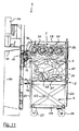
図13は、図12の右側、観察者からそれる側の方向における垂直断面の図12に描かれる要素を示し、それによって、コレクタワゴン2はここでは連結されている。4個のロータリーグラインダ31とその上に配置されるカバー35を有するフィーダデバイス3は、図13中、頂部に見られる。操作中に、ロータリーグラインダ31は、図13に従い、その見える方向に反時計回りに回転し、底からフィーダデバイス3へ送られる圧縮可能物に対して送り力が左から右へ働く。
FIG. 13 shows the elements depicted in FIG. 12 in a vertical section in the direction of the right side of FIG. 12, away from the observer, whereby the
なおここでは描かれていないプレスの装填開口内又はその直前に配置される装填デバイス12は、フィーダデバイス3の右側に続く。ここでは、装填デバイス12は、搬送歯を有し、回転装置によって駆動され得、圧縮可能物をプレスの装填開口を介してプレスのプレス室へ搬送するローターローラを備える。
Note that the
ローラ25で変位可能な連結されたコレクタワゴン2は、フィーダデバイス3の下方に位置される。フィーダデバイス3に対してコレクタワゴン2を正確に位置決めするために、フィーダデバイス3の見えない連結ガイドと交わり、ここで係合するレール形状の連結ガイド27は、側壁24の上縁に配置される。図13では左を指すその後ろ側に、コレクタワゴン2は、スライドハンドル28を有する。底21と後壁22は、組み合わされて底−壁要素21、22を形成し、垂直方向へ一緒に変位され得る。この変位は、持ち上げデバイス4によって行われる。
A
対応するシャフト47’を有する持ち上げデバイス4のギアホイール47の一方が図13に見える。コレクタワゴン2が連結されると、ギアホール47は、コレクタワゴン2の後壁22の内側に配置されるギアラック48と直ちに係合される。描かれた例示の実施の形態において、ギアラック48は、後壁22内又はその上で垂直方向へ延出するプロファイル48’に取り付けられ、且つ少なくとも二つの端部でクランプされ固定される、ローラチェーンの一部である。或いは、又はそれに加えて、ローラチェーンは、プロファイル48’への溶接等によって選択的に又は全長を介して後壁22へ接続されギアラック48を形成することができる。持ち上げデバイス4がオンにされると、ギアホイール47は、コレクタワゴン2を空にするために時計回りに回転し、それによって、底−壁要素21、22は、ギアラック48を介してコレクタワゴン2のコレクタ室20内に収集された圧縮可能物と共に上方へ移動される。ギアホイール47の回転の方向は、空にした後、底−壁要素21、22を下降するために反転される。
One of the
ここではロックされた位置にあるロックバー装置15は、図13中左上に見える。このため、ロックバー装置15は下方へ回動され、上方から後壁22の上部の背後に係合する。このロックされた位置において、ロックバー装置15は、ロックバーハンドル15.1を回動することによってロックされる。
Here, the
更に、ロックバー装置15は、ギアホイール47とギアラック48との確実な係合状態を保つ2個のコンタクトローラ49を有する。このために、コンタクトローラ49は、夫々、ギアラック48が位置する前側でギアラック48から離れるように向くプロファイル48’の後側を押圧する。底−壁要素21、22を持ち上げ及び降下する際、ギアラック48は、プロファイル48’と共に、その都度、ギアホイール47とコンタクトローラ49の間で夫々上方又は下方へ走行する。磨耗を補償するため、コンタクトローラ49は、再調整可能なことが有利である。遊びがないギアホイール47とギアラック48との係合は、このように永続的に確保される。
Further, the
図12と同様の表現で、図14は、ここでは連結された位置にあるがまだ固定されてはいないコレクタワゴン2と共にフィーダデバイス3を示す。ロックバー装置15は、全体として、ここでは下方へ回動されており、それによって、ロックバーハンドル15.1を有する、観察者に面するその装置の後部は、ここで、上方へ延出されたコレクタワゴン2の後壁22上部の前及び背後で係合する。ダッシュ線によって示される、ロックバー装置15の後部の更なる回動移動によって、ロックバー装置15は、その最終ロック位置に移行される。図14において、頭付きボルト15.5は、ロックバー装置15のスロット形成スライダ15.3とまだ係合していない。
In a representation similar to FIG. 12, FIG. 14 shows the
図14における更なる参照番号に関しては、前の記述を参照されたい。 See the previous description for further reference numbers in FIG.
図15は、背後から見たロックバー装置15をそのロック位置で単独で示している。このロック位置において、ロックバーハンドル15.1は、オペレータによって下方へ回動され、それによって、トグルレバー装置15.2は、伸張された自己ロック過剰死点位置を取る。同時に、スロット形成スライダ15.3は、ロックバーハンドル15.1を回動することによって下方へ変位し、それによって、スライダ15.3のスロットが頭付きボルト15.5の頭の背後に係合する。スライダ15.3は、同時に、斜めガイド15.4によって、頭付きボルト15.5に対してその軸方向へ引っ張られる。このロック位置において、ロックバー装置15は、その位置で、頭付きボルト15.5に対して、従ってフィーダデバイス3に対して固定される。ここでは図示されていないコレクタワゴン2の後壁22がロックバー装置15とフィーダデバイス3との間に位置されていることから、コレクタワゴン2もまた、ロックバー装置15がフィーダデバイス3に対してロック位置にある時、正確に位置決めされ固定される。
FIG. 15 shows the
図16乃至21は、更なる例示の実施の形態を示し、その場合、持ち上げデバイス4のギアラック48はコレクタワゴン2上に配置されるのではなく、フィーダデバイス3上に配置される。
FIGS. 16 to 21 show a further exemplary embodiment, in which case the
図16は、背後からの斜視図において、接続された持ち上げデバイス4を有するフィーダデバイス3を接続されるコレクタワゴン2と共に示す。ここで、フィーダデバイス3は、上述の例示の実施の形態に従って再び具体化される。これに関しては、前の記述を参照されたい。
FIG. 16 shows the
図16において、持ち上げデバイス4は、観察者に面するフィーダデバイス3の後ろ側に配置される。ここで、また、持ち上げデバイス4は、共通のシャフト47’に配置され図16では覆われて見られない二つのギアホイールを有する。シャフト47’は、電気モータとアングルギアよりなる駆動装置44によって回転可能である。持ち上げデバイス4は、更に、二つの側方垂直縁の両方でギアラック48を支える持ち上げキャリッジ42を備える。これらのギアラック48は、シャフト47’のギアホイールと安定して係合される。持ち上げキャリッジ42は、連結されるコレクタワゴン2に面する側で斜め上方へ向く突起を含む二つの水平方向へ延出する第1の支持帯46’を備える。駆動装置44をオンすることによって、持ち上げキャリッジ42は、その支持帯46’によって垂直方向上下に変位され得る。
In FIG. 16, the
被プレス圧縮可能物、例えば、段ボール箱等の包装材料5がそのコレクタ室20に収集される、連結されるコレクタワゴン2は、図16の右側に見られる。フィーダデバイス3及び持ち上げデバイス4に対してコレクタワゴン2を正確に位置決めするため、オペレータは、ローラ25を有するコレクタワゴン2をスライドハンドル28でプレスの設置空間の底に配置及び固定された二つの平行なガイドレール65内に案内する。ローラ25のガイドローラ65への挿入を容易にするために、ガイドローラ65は、夫々、図16の右に位置されるそのスタート領域に漏斗形状の入口面取り面を有する。反対側の端部に、夫々、ガイドレール65は、先頭ローラ25に対するストップを有する。
The
本発明の前述の例示の実施の形態の場合のように、図16のコレクタワゴン2の底21と後壁22は、残りのコレクタワゴン2に対して垂直に変位可能な底−壁要素21、22を形成するように互いに接続される。観察者に向く後壁22の外側で、互いに平行な二つの平行な支持帯26’が固定され、それらは、外方且つ斜め下方へ向く突起を含む。コレクタワゴン2を矢印方向へフィーダデバイス3の下方へ挿入することによって、持ち上げデバイス4の第1の支持帯46’とコレクタワゴン2の第2の支持帯46’とが直接上下に位置するよう隣接位置になる。
As in the previous exemplary embodiment of the present invention, the bottom 21 and
図16と同様の表現で、図16に示されるプレスの部分は、図17に示され、それによって、ここで、コレクタワゴン2が連結され、持ち上げキャリッジ42が、底−壁要素21、22と共にセクションによって上方へ変位される。連結状態において、コレクタワゴン2の先頭ローラ25は、図17では、ガイドレール65の左端のストップ上に位置している。更に、持ち上げデバイス4の第1の支持帯46’は、ここで、図17では覆われ、従って、コレクタ室20内に位置する圧縮可能物と共に底−壁要素21、22を支持する、コレクタワゴン2の後壁22上の第2の支持帯26’の下に係合する。第1の支持帯46’と第2の支持帯26’との係合は、持ち上げキャリッジ42を単にその最下位置から持ち上げることによって且つ逆に持ち上げキャリッジ42をその最下位置へ降下することによって底−壁要素21、22を持ち上げるための技術的に単純な方法で係合解除される。
In a representation similar to FIG. 16, the portion of the press shown in FIG. 16 is shown in FIG. 17, whereby the
図18は、図16及び図17左側の側面図で図16及び図17の持ち上げデバイス4とコレクタワゴン2を有するフィーダデバイス3を示す。前述のフィーダデバイス3は、図18の上部に見られる。装填デバイス12は、左方向へ、従って、なおここでは図示されないプレスに向かう方向へフィーダデバイス3に続く。
FIG. 18 shows the
駆動装置44及びシャフト47’を有する持ち上げデバイス4は、そこに配置されるギアホイール47の一方と共に図18の右側に見られる。ギアホイール47は、垂直方向へ変位可能な持ち上げキャリッジ42の一部を形成するプロファイル48’に取り付けられるギアラック48に係合される。図18の右側に面するフィーダデバイス3の後ろ側に、互いに距離を置いて垂直に配置され、持ち上げキャリッジ42が上方又は下方へ移動する際、その上をプロファイル48’がギアラック48から離れた側で走行する二つのコンタクトローラ49が持ち上げデバイス4の一部として配置される。コンタクトローラ49を水平方向へ調節することによって、遊びのない係合がギアホイール47とギアラック48との間で調節され得る。
A
コレクタワゴン2は、フィーダデバイス3の下方において、そのローラ25をガイドレール65内に位置させている。持ち上げキャリッジ42の二つの平行な第1の支持帯46’と相互作用する(interact)二つの支持帯26’は、図18の右側に位置する後壁22に取り付けられる。持ち上げデバイス4の第1の支持帯46’は、持ち上げキャリッジ42がその最下位置を取る図18に示される持ち上げデバイス4のベース位置においてコレクタワゴン2の後壁22の第2の支持帯26’の僅かに下方に位置される。
The
持ち上げデバイス4の駆動装置44がオンにされると、ギアホイール47が持ち上げキャリッジ42を持ち上げるために時計回りに回転し、それによって、第1の支持帯46’は、コレクタワゴン2の後壁22上の第2の支持帯26’の底側に当接する。持ち上げキャリッジ42を更に上方へ変位することによって、支持帯46’は、底21と後壁22よりなる底−壁要素21、22をコレクタワゴン2に収集された圧縮可能物と共に持ち上げ、それによって、圧縮可能物は、フィーダデバイス3の底側へ移動される。次に、フィーダデバイス3は、頂部から圧縮可能物を除去し、装填デバイス12を介して対応するプレスのプレス室にそれを送ることができる。
When the
コレクタワゴン2を空にした後、持ち上げキャリッジ42は、駆動装置44によって再度経路切り替えされ、それによって、底−壁要素21、22もまた、図18の位置に再び達するまで、持ち上げキャリッジ42と共に降下される。ここで、オペレータは、プレスから離れた距離にある位置においてコレクタワゴン2で圧縮可能物を再び収集できるように、スライドハンドル28によってフィーダデバイス3の下からコレクタワゴン2を押し出す又は引き出すことができる。
After emptying the
図19は、上面図で、フィーダデバイス3及び持ち上げデバイス4の一部を示し、それによれば、図18のフィーダデバイス3及び持ち上げデバイス4の右前縁領域が上から見える。対応するシャフト47’を有するギアホイール47の一方は、図19では底右側に見える。矩形プロファイル48’に取り付けられ、それに平行に延出するギアラック48は、図19の図面平面に垂直なギアホイール47の左へ延出する。例えば、ポリアミド製の、矩形プロファイル48’に平行に延出し、上に持ち上げキャリッジ42がスライドするように載るスライド部材49’は、低摩擦に応じてギアホイール47とギアラック48との間で遊びのない係合を調節するように働く。ギアラック48から離れた側では、矩形プロファイル48’は、図19では、上側のみが見える、互いに垂直方向へ離間している2個のコンタクトローラ49に支えられている。フィーダデバイス3の僅かな部分が図19ではなお左側に見える。
FIG. 19 shows in top view a part of the
図20は、互いに直角に延出する、設置領域6の二つの壁60のコーナー領域において設置空間6に配置されるプレス1を上面図で示す。プレス1はその内部にプレス空間10を有し、そこでは、ここでは見られない押圧プレートが電力駆動装置14によって垂直方向へ変位可能である。図20において、プレス1の前側は、左を指す。ここでは開放状態で示されるドア16は、プレス1のこの前側に位置する。ドア16のこの開放位置において、プレス1で生成される圧縮梱50がプレス室10から除去され得る:圧縮梱を、例えば、搬送パレット上へ向けて前方へ傾けることができる。プレス1の後ろ側、即ち、図20では右側に配置され且つ機械的装填のために働く装填開口11に加えて、設けられる更なる装填開口11’は、ドア16の上方へ配置される。オペレータは、圧縮可能物、特に、コレクタワゴン2の使用に価値がない残量又は少量の物をこの更なる前側装填開口11’を介してプレス1のプレス室10内に手作業で導入することができる。
FIG. 20 shows in a top view the
プレス1へ連結されるコレクタワゴン2は、図20では、プレス1の上方、即ち、その左側に描かれている。また、コレクタワゴン2は、ここでは、後壁22、前壁23並びに二つの側壁24を有し、これらの壁は底21と共にコレクタ室20を形成し、このコレクタ室内に圧縮可能物をプレス1から離れた位置で収集することができる。コレクタワゴン2をダッシュ矢印の方向へ変位することによって、コレクタワゴン2の底側に配置されたローラがガイドレール65に到達し、そこで、コレクタワゴン2は、確実にその方向へ案内されるようフィーダデバイス3の下に完全にスライドされる。この位置で、持ち上げデバイス4及びフィーダデバイス3は、前述の方法で支持帯46’、26’を介して底−壁要素21,22を機械的に持ち上げるように且つ後側装填開口11を介してフィーダデバイス3と装填デバイス12とによってプレス1のプレス室10内にコレクタ室20から圧縮可能物を搬送するように起動され得る。プレス1を、その後側が一方の壁60に向きその側方側、ここでは、その右側が他方の壁60に向くように、二つの壁60に近接する部屋のコーナーに設置することができる。コレクタワゴン2の連結及び連結解除は、プレス1の他方の側方側から、ここでは、その左側から行われる。
The
図21は、正面図で、フィーダデバイス3、持ち上げデバイス4並びに図20の連結されるコレクタワゴン2と共にプレス1を示す。プレス1は図21の右側に見られ、ここでは、プレス1の正面側が見られる。それを通して圧縮梱をプレス1のプレス室10から除去可能なドア16がこの正面側に配置される。ここでは開いており、従って、プレス室10内が見える更なる装填開口11’は、ドア16の上側に具体化される又はドア16の一部として具体化される。プレス室10内で垂直に変位可能な見られない押圧プレートのための電力駆動装置14は、プレス1の上部に配置される。
FIG. 21 is a front view showing the
フィーダデバイス3及び持ち上げデバイス4の一部は、観察者から離れた側のプレス1の後側に見られる。ここで、その後壁22が観察者から離れる方に向いている、連結されるコレクタワゴン2は、プレス1の左側に配置される。オペレータは、ダッシュ矢印で示されているように、スライドハンドル28によってローラ25を有するコレクタワゴン2をガイドレール65内に挿入することができる。中に収集された圧縮可能物と共にコレクタワゴン2の底−壁要素21、22を、第1の支持帯46’を有する持ち上げデバイス42によって持ち上げることができる。フィーダデバイス3は、コレクタワゴン2から圧縮可能物を上方から除去して、それを図21では見えない装填デバイス12を介して水平方向前方へプレス室10内に送る。圧縮可能物がプレス室10から前方へ落ちないように、前側装填開口11’は有利には、プレス室10の機械的装填に応答して閉鎖され、次に、言うまでもなくドア16が閉鎖される。
A part of the
図22は、なお、ここでは描かれていないプレスの部品として装填デバイス12、フィーダデバイス3及び持ち上げデバイス4を連結されたコレクタワゴン2と共に示す。フィーダデバイス3は、ここでは、コレクタワゴン2の左側へ描かれなければならない、非図示の残りのプレスの装填側へ接続される。装填デバイス12は、プレスの装填開口に及びより適切には部分的に配置される。
FIG. 22 shows the
フィーダデバイス3は、ここでは4つのロータリーグラインダを含み、これらロータリーグラインダは互いに平行に延出し、回転装置によって駆動され、上カバー35の下側、サイドフランジ33と図面平面に直交するその回転軸との間に配置される。動作中、ロータリーグラインダは、電気モータとアングルギアよりなる共通の駆動装置34の同じ方向、かつ、互いに異なる回転速度で回転可能である。それによって、装填デバイス12に最も近いロータリーグラインダは、最高の回転速度を有するが、装填デバイス12から最も遠いロータリーグラインダは、最小の回転速度を有する。
The
コレクタワゴン2は、矩形底21、並びに後壁22、前壁23及び二つの側壁24を有し、これらは、一緒に、上に向かって開口するコレクタ室を画定する。コレクタワゴン2は、ローラ25上に配置され得、それによって、オペレータは、スライドハンドル28によってコレクタワゴン2をつかみ、操舵することができる。底21は、残りのコレクタワゴン2に対して全体として垂直方向へ変位可能に案内される底−壁要素21、22を形成するように後壁22へ接続される。
The
持ち上げデバイス4は、図22では右側を指す、コレクタワゴン2及びフィーダデバイス3の後側に配置される。持ち上げデバイス4は、ここでは覆われている持ち上げキャリッジが持ち上げ駆動装置44によって垂直に変位可能な垂直平面に配置される持ち上げフレーム41を備える。持ち上げキャリッジは、コレクタワゴン2の方向へ突出し且つコレクタワゴン2、より正確には、コレクタワゴンの後壁22に配置されるフック収容部26と係合及びそれから係合解除可能なフック46を有する。図22に示されているように、コレクタワゴンが連結されると、且つ係合が確立されると、コレクタワゴン2の底−壁要素21、22は、持ち上げ駆動装置44によって持ち上げ方向40へその中の圧縮可能物と共に上方へ移動され得、それによって、フィーダデバイス3が同時にオンされると、フィーダデバイス3は、コレクタワゴン2から圧縮可能物を上方から除去して、なお、図示されていないプレスのプレス室内にそれを左側へ送る。
The
装填デバイス12、フィーダデバイス3及び持ち上げデバイス4、好ましくは、それらの駆動装置12.4、34及び44は、更に、夫々、ここでは図示されていない、電力消費等を把握する電力要求センサを備える。図示されていない、好ましくは、電子制御ユニットが、プレス1に割り当てられ、それに対して電力要求センサの測定信号が送られ、それによって、装填デバイス12、フィーダデバイス3及び/又は持ち上げデバイス4、又はそれらの駆動装置12.4、34及び44の出力は、夫々、送られた測定信号に従って、変更及び/又はその動作方向が反転可能である。このように、一つ以上の電力要求センサによって把握される切迫した過負荷は、損傷が引き起こされる前に、自動制御の介在によって対処され得、そこでは、一つ以上の駆動装置の出力が、減少されるか又は動作方向が反転される。ある時間経過後、夫々の駆動装置の出力は、プレス室の充填を続けるように、夫々、再び自動的に増加される又は通常の動作方向へ戻されることが可能である。
The
図23は、上からの斜視図において、図22に示されるプレスの個々の部品として押圧プレート13並びにローターローラ12.1を示す。押圧プレート13は、プレスのプレス室内で上下に垂直に変位され得、それによって、プレスストロークは、最上部から最下部まで発生する。それによって、押圧プレート13は、ローターローラ12.1の上側の位置とその下側の位置の間を移動する。ローターローラ12.1によって、可能な限り圧縮可能物をプレスのプレス室へ送ることができるようにするため、ローターローラ12.1の搬送歯12.2は、押圧プレート13の移動領域内に突出する。相互の衝突と損傷を防止するため、押圧プレート13は、ローターローラ12.1に面する縁で搬送歯12.2と整合するように配置される通路スロット13’を含む。押圧プレート13が、その垂直移動に応じてローターローラ12.1を通過して移動すると、プレス室内に突出する搬送歯12.2は、押圧プレート13と衝突することなく、押圧プレート13の通路スロット13’を通過して走行する。この配置により、装填デバイス12のローターローラ12.1がプレスのプレス室内に突出する場合、ローターローラ12.1は、特に効果的な方法で、圧縮可能物をプレス室内へ送ることができる。通路スロット13’が比較的小さな深さと幅を含むに過ぎないことから、これらのスロットは、押圧プレート13の安定性とプレス機能に影響を及ぼさない。
FIG. 23 shows, in a perspective view from above, the
図24は、装填デバイス12のローターローラ12.1の心棒12.3に対して垂直に延出する垂直断面図で装填デバイス12及びプレスの押圧プレート13の一部を示す。図24に描かれているように、ローターローラ12.1は、プレスの装填開口11の直前より適切には部分的に入るように位置し、それによって、ローターローラ12.1の突出搬送歯12.2は、プレス室10内に突出する。プレス室10内で垂直に変位可能な押圧プレート13は、具体的には、ローターローラ12.1のレベルの位置に配置される。それによって、搬送歯12.3の一つが押圧プレート13の対応する通路スロット13’を如何に通過するか見ることができる。
FIG. 24 shows a part of the
ローターローラ12.1の搬送歯12.2の外側先端の軌跡から近い距離に配置されるガイド表面12.5は、ローターローラ12.1の上に見える。ガイド表面12.5は、回動することができ、ローターローラ12.1からのその距離は、ガイド表面12.5の左端に設けられるジョイントによって、例えば、機械的又はモータ駆動調節手段によって又は更にここでは図示されていないスプリングの力のような事前加重力に抗する、送られる圧縮可能物によって調節され得る。ガイド表面12.5は、搬送歯12.2と送られる圧縮可能物との確実な係合を確保する。 A guide surface 12.5 arranged at a distance close to the trajectory of the outer tip of the conveying teeth 12.2 of the rotor roller 12.1 is visible on the rotor roller 12.1. The guide surface 12.5 can be pivoted and its distance from the rotor roller 12.1 can be determined by a joint provided at the left end of the guide surface 12.5, for example by mechanical or motor drive adjustment means or further It can be adjusted by the compressible being sent against pre-loading forces such as spring forces not shown here. The guide surface 12.5 ensures a positive engagement between the conveying teeth 12.2 and the compressible material being fed.
図25は、断面図で、フィーダデバイス3、持ち上げデバイス4及び装填デバイス12を備える完全なプレス1を連結されたコレクタワゴン2と共に示し、それによって、図22とは反対に、コレクタワゴン2は、ここでは左側に位置し、プレス1は、右側に位置している。図25の頂部に、フィーダデバイス3が4つのロータリーグラインダ31とその上に配置されたカバー35と共に見られる。動作中、ロータリーグラインダ31は、図23に従って見る方向へ反時計回りに回転し、それによって、送り力は、底からフィーダデバイス3へ送られる圧縮可能物に対して左側から右側へ作用する。最後のロータリーグラインダ31の粉砕歯間に突出し且つ圧縮可能物を歯から除去するスクレーパ36は、確実に圧縮可能物を装填デバイス12へ搬送するために、装填デバイス12に向く最後のロータリーグラインダ31に割り当てられる。
FIG. 25 shows in cross section the
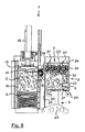
右側に、ここで描かれるプレス1の装填開口11の直前に及び部分的にその中に配置される装填デバイス12は、フィーダデバイス3に続く。ここで、装填デバイス12は、搬送歯を備え且つ回転装置によって駆動可能な、圧縮可能物をプレス1の装填開口11を介してプレス1のプレス室10内へ搬送するローターローラ12.1を備える。図25に従い、その見える方向に見て、装填デバイス12のローターローラ12.1は、動作中に時計回りに回転し、それによって、圧縮可能物は、ローターローラ12.1の上側とその上に配置されるガイド表面12.5との間を搬送され、斜め下方を指す移動コンポーネントによってプレス室10内へ送られる。
On the right side, the
ローラ25上に配置可能な連結されたコレクタワゴン2は、フィーダデバイス3の下方へ位置される。図25で右側を指すその前側で、コレクタワゴン2は、二つの側壁24を横切るように延出可能なスライドハンドル28を有する。底21及び後壁22は、組み合わされて底−壁要素21、22を形成し、且つ垂直方向へ一緒に変位され得る。この変位は、持ち上げデバイス4によって実行される。
A
持ち上げデバイス4の、持ち上げ駆動装置44を有する持ち上げフレーム41の一部は、図25に見られる。ここで、持ち上げデバイス4は、フィーダデバイス3に機械的に接続され、それによって支持される。持ち上げデバイス4がオンされると、底−壁要素21、22は、コレクタワゴン2のコレクタ室20内に収集された圧縮可能物と共に上方へ持ち上げ方向40へ移動される。持ち上げデバイス40の動作方向は、空にした後、反転されて底−壁要素21、22を降下する。
A part of the lifting
完了した圧縮梱をプレス1のプレス室10から除去可能なドア16は、右側を指すプレス1の前側に位置する。このため、プレス1は、実施の形態を有し、それ自体既知であり、且つ図25の左側に位置する後壁上のプレス室10の底領域から上方へ延出する圧縮梱排出装置17を含む。圧縮梱が完全にプレスされ、該当する場合、プレス室10内で結束されると、ドア16が開き、圧縮梱排出装置17が起動される。圧縮梱排出装置17は、プレス室10内の圧縮梱をプレス室10の後側に沿って上方へ移動し、同時に、圧縮梱を前方へ傾け、圧縮梱は、プレス室10から開いたドア16を通って出るように約90°傾く。例えば、その上で圧縮梱が傾けられるパレットを、圧縮梱を更に搬送するためにプレス1の前に配置することができる。ドア16を閉鎖し圧縮梱排出装置17をそのベース位置へ戻すように移動すると、更なる圧縮梱を形成するために、圧縮可能物を再供給し、プレス1内で圧縮することができる。
The
ここでは、単純な又はダブルピストン−シリンダユニットの形態で、プレス室10内で垂直に変位可能な、押圧プレート13のための電力駆動装置14は、プレス1の上部に配置される。
Here, a
図26は、部分垂直断面図で、図25からの圧縮梱排出装置17の一部と共に装填デバイス12を示す。圧縮梱排出装置17がローターロール12.1の搬送歯12.2の移動領域内で起動され持ち上げられた位置にあるのが分かる。圧縮梱排出装置17とローターローラ12.1の間で損傷する衝突を確実に防止するため、ローターローラ12.1の現在の回転位置を捕獲しそれを制御ユニットに転送する少なくとも一つの回転位置センサがローターローラ12.1へ割り当てられる。ローターローラ12.1が停止されると、回転位置センサに従って、制御ユニットは確実に、ローターローラを、その突出する搬送歯12.2に関してある回転位置で停止させる。それによって、この特定の回転位置は、圧縮梱排出装置17が完了した圧縮梱の排出のための起動に応答して下から上方へ移動された際、搬送歯11.2がもはや圧縮梱排出装置17と接触しないように画定される。
FIG. 26 is a partial vertical cross-sectional view showing the
図24と同様、図26は、更に、ローターローラ12.1の心棒12.3並びにその上に配置されたガイド表面12.5を示す。 Similar to FIG. 24, FIG. 26 further shows the mandrel 12.3 of the rotor roller 12.1 and the guide surface 12.5 disposed thereon.
図27は、最後に、垂直断面図で、個々の部品として図22のプレス1の持ち上げデバイス4を示す。持ち上げデバイス4の支持部は、垂直平面に配置される持ち上げフレーム41を形成する。持ち上げキャリッジ42は、キャリッジガイド42”によって案内されながら、持ち上げフレーム41に沿って垂直に上方へ及び下方へ変位され得る。ここでは見えず且つ断面平面前に位置される持ち上げ駆動装置、例えば、動作中に二つのギアホイール48.1及び48.1’の一方を駆動する、ギア機構を有する電気モータや油圧モータは、ここでは、持ち上げキャリッジ42を変位するように働く。ギアホイール48.1及び48.1’は、上下に同じ垂直方向距離を有して持ち上げフレーム41の最上部と最下部に支持されており、ローラチェーン等の連続トラクション機構47.1がこれら二つのギアホイール48.1及び48.1’にわたって案内される。
FIG. 27 finally shows the
図27において、持ち上げキャリッジ42は、最下位置を取り、その下端でトラクション機構47.1へ結合されているに過ぎず、大きな変位パスがギアホイール48.1と48.1’との距離に事実上対応する持ち上げキャリッジ42に従う。ここでは、二対の二つの突出フック46が、夫々、持ち上げキャリッジ42に配置される。これらのフックは、コレクタワゴン2内の圧縮可能物を図25に従ってフィーダデバイス3の方向へ上方に移動するように、及び圧縮可能物を除去した後に底−後壁要素21、22を再び下方へ移動するように、底−後壁要素21、22のような垂直に移動可能な部品とより正確に連結されるコレクタワゴン2と係合するように働く。次に、コレクタワゴン2は、持ち上げデバイス4から再び連結解除され得、圧縮可能物のための収集位置へ運ばれ得る。
In FIG. 27, the lifting
1 プレス
10 プレス室
11 後側装填開口
11’ 前側装填開口
12 装填デバイス
12.1 ローターローラ
12.2 搬送歯
12.3 心棒
12.4 駆動装置
12.5 ガイド表面
13 押圧プレート
13’ 32のための通路スロット
14 電力駆動装置
15 ロックバー装置
15.1 ロックバーハンドル
15.2 トグルレバー装置
15.3 スロット形成スライダ
15.4 斜めガイド
15.5 頭付きボルト
16 ドア
17 圧縮梱排出装置
2 コレクタワゴン
20 コレクタ室
21 底
22 後壁
22’ 後壁ガイド
23 前壁
24 側壁
25 ローラ
26 46のための収容部
26’ 第2の支持帯
27 2上の連結ガイド
28 スライドハンドル
3 フィーダデバイス
30 送り方向
31 ロータリーグラインダ
31’ コンベアベルト
32 コンベア歯
33 サイドフランジ
34 駆動装置
35 カバー
36 スクレーパ
37 3上の連結ガイド
4 持ち上げデバイス
40 持ち上げ方向
41 持ち上げフレーム
42 持ち上げキャリッジ
42’ 持ち上げアーム
42” キャリッジガイド
43 2内のはさみタイプ持ち上げ装置
44 持ち上げ駆動装置
45 折り畳みレバー
46 フック
46’ 第1の支持帯
47 48に対するギアホイール
47’ シャフト
47.1 連続トラクション機構
48 ギアラック
48’ 矩形プロファイル
48.1 47.1に対するギアホイール
48.1’ 47.1に対するギアホイール
49 コンタクトローラ
49’ スライド部材
5 圧縮可能物
50 圧縮梱
6 設置空間
60 6の壁
65 ガイドレール
DESCRIPTION OF
Claims (23)
前記フィーダデバイス(3)は、少なくとも前記底(21)を少しずつ上方へ移動することによって、且つ、前記コレクタワゴン(2)から前記圧縮可能物(5)を上方から連続的に除去することによって、ならびに、前記圧縮可能物(5)を前記プレス(1)へ送ることによって、前記コレクタワゴン(2)内の前記圧縮可能物(5)を捕獲するフィーダとして具体化されることを特徴とするプレス。 A press (1) having at least one collector wagon (2) for pressable compressibles (5) that can be connected and disconnected, said press (1) comprising a press chamber (10), When the collector wagon (2) includes a collector chamber (20) having a bottom (21) and walls (22, 23, 24), and the collector wagon (2) is connected to the press (1), the collector wagon (2) The compressible material (5) housed in can be mechanically transferred from the collector wagon (2) into the press chamber (10), at least the bottom (21) of the collector wagon (2) There to the collector wagon (2) empty, resulting is vertically displaced from the lower collecting position upward, the feeder device (3) is provided, by moving at least the bottom (21), said Kore When the Tagon (2) is connected to the press (1), the feeder device (3) causes the compressible material (5) in the collector chamber (20) to move into the press chamber (of the press (1) ( 10), and the collector wagon (2) is in a position distant from the press (1) and disconnected from the press (1), and the press-compressible object is In press (1), which can be filled with (5)
The feeder device (3) moves at least the bottom (21) little by little upward and continuously removes the compressible material (5) from the collector wagon (2) from above. And as a feeder for capturing the compressible material (5) in the collector wagon (2) by sending the compressible material (5) to the press (1). press.
前記ロータリーグラインダ(31)は、歯を備え、隣接する前記ロータリーグラインダ(31)の前記歯は、互いに対してオフセットして配置され、長手ロータリーグラインダ方向に見てオーバーラップ半径で互いに係合することを特徴とする請求項3に記載のプレス。 The feeder device (3) is embodied as a rotary cutter having a plurality of parallel rotary grinders (31) that can be driven in the same direction by a rotating device,
The rotary grinder (31) includes teeth, and the teeth of adjacent rotary grinders (31) are arranged offset with respect to each other and engage each other with an overlap radius when viewed in the longitudinal rotary grinder direction The press according to claim 3.
前記ロータリーグラインダ(31)は、互いに異なる回転速度で駆動され得、前記プレス室(10)に最も近い前記ロータリーグラインダ(31)は、最高の回転速度を有し、前記プレス室(10)から最も遠い前記ロータリーグラインダ(31)は、最低の回転速度を有することを特徴とする請求項3又は4に記載のプレス。 The feeder device (3) is embodied as a rotary cutter having a plurality of parallel rotary grinders (31) that can be driven in the same direction by a rotating device,
The rotary grinder (31) can be driven at different rotational speeds, and the rotary grinder (31) closest to the press chamber (10) has the highest rotational speed and is the highest from the press chamber (10). The press according to claim 3 or 4, characterized in that the remote rotary grinder (31) has the lowest rotational speed.
前記フィーダデバイス(3)、持ち上げデバイス(4)及び前記装填デバイス(12)は、夫々、電力要求センサを備え、
前記持ち上げデバイス(4)が前記プレス(1)又は前記フィーダデバイス(3)に設けられ、前記コレクタワゴン(2)が前記プレス(1)へ連結されると、前記持ち上げデバイス(4)が、前記コレクタワゴン(2)の少なくとも前記底(21)又は前記コレクタワゴン(2)の前記底−壁要素(21、22)を持ち上げ、且つ降下させることができ、 制御ユニットが、プレス(1)に割り当てられ、前記電力要求センサの測定信号を制御ユニットに送ることができ、前記制御ユニットによって、送られた測定信号に従い、前記フィーダデバイス(3)、前記持ち上げデバイス(4)及び/又は前記装填デバイス(12)の出力は、変化され得る及び/又はフィーダデバイス(3)、前記持ち上げデバイス(4)及び/又は装填デバイス(12)の動作方向が反転され得ることを特徴とする請求項1〜7及び請求項9〜18のいずれか1項に記載のプレス。 An active loading device (12) of the press (1) is arranged between the feeder device (3) and the press chamber (10);
The feeder device (3), lifting device (4) and loading device (12) each comprise a power demand sensor,
When the lifting device (4) is provided in the press (1) or the feeder device (3) and the collector wagon (2) is connected to the press (1), the lifting device (4) At least the bottom (21) of the collector wagon (2) or the bottom-wall element (21, 22) of the collector wagon (2) can be lifted and lowered, and a control unit is assigned to the press (1) And the measurement signal of the power demand sensor can be sent to a control unit, and according to the measurement signal sent by the control unit, the feeder device (3), the lifting device (4) and / or the loading device ( the output of 12) is altered may and / or feeder device (3), the lifting device (4) and / or loading device ( Press according to any one of claims 1-7 and claim 9 to 18 in which the direction of movement of the 2) is characterized in that can be reversed.
Applications Claiming Priority (7)
| Application Number | Priority Date | Filing Date | Title |
|---|---|---|---|
| DE102009047297A DE102009047297A1 (en) | 2009-11-30 | 2009-11-30 | Press i.e. baling press, for use in e.g. consumer market, has conveying device detaching press material form top under upward movement of base and conveying press material to press chamber when collecting carriage is coupled with press |
| DE102009047297.5 | 2009-11-30 | ||
| DE201010000938 DE102010000938A1 (en) | 2010-01-15 | 2010-01-15 | Press for e.g. large super market, has conveying device conveying material upward to press chamber by moving base upward little by little, and continuously removing material from wagon from above and feeding material to press |
| DE102010000938.5 | 2010-01-15 | ||
| DE201010031168 DE102010031168A1 (en) | 2010-07-09 | 2010-07-09 | Press for e.g. large super market, has conveying device conveying material upward to press chamber by moving base upward little by little, and continuously removing material from wagon from above and feeding material to press |
| DE102010031168.5 | 2010-07-09 | ||
| PCT/EP2010/068384 WO2011064357A2 (en) | 2009-11-30 | 2010-11-29 | Press having at least one collector wagon that can be coupled and uncoupled |
Publications (2)
| Publication Number | Publication Date |
|---|---|
| JP2013512107A JP2013512107A (en) | 2013-04-11 |
| JP5574251B2 true JP5574251B2 (en) | 2014-08-20 |
Family
ID=44012600
Family Applications (1)
| Application Number | Title | Priority Date | Filing Date |
|---|---|---|---|
| JP2012540451A Active JP5574251B2 (en) | 2009-11-30 | 2010-11-29 | Press having at least one collector wagon that can be connected and disconnected |
Country Status (11)
| Country | Link |
|---|---|
| US (1) | US9321231B2 (en) |
| EP (1) | EP2507046B1 (en) |
| JP (1) | JP5574251B2 (en) |
| AU (1) | AU2010323073B2 (en) |
| BR (1) | BR112012012852B1 (en) |
| CA (1) | CA2781756C (en) |
| DK (1) | DK2507046T3 (en) |
| ES (1) | ES2443579T3 (en) |
| PL (1) | PL2507046T3 (en) |
| RU (1) | RU2508201C1 (en) |
| WO (1) | WO2011064357A2 (en) |
Cited By (1)
| Publication number | Priority date | Publication date | Assignee | Title |
|---|---|---|---|---|
| KR20210146718A (en) * | 2020-05-27 | 2021-12-06 | (주)삼일무역 | Automatic vertical clothing compression device |
Families Citing this family (10)
| Publication number | Priority date | Publication date | Assignee | Title |
|---|---|---|---|---|
| DE102012222232A1 (en) | 2012-12-04 | 2014-06-05 | Sib Strautmann Ingenieurbüro Gmbh | Device for removing waste e.g. paper, has conveyor that is provided to convey waste accumulated in trolley to garbage chute in horizontal direction through insertion opening |
| CN104121841B (en) * | 2014-07-25 | 2017-01-25 | 环驰轴承集团有限公司 | Full-automatic bearing appearance inspection machine |
| CN104354319A (en) * | 2014-11-07 | 2015-02-18 | 四川红七公食品有限公司 | Semiautomatic settling type pickle squeezer |
| DE102015111296A1 (en) | 2015-07-13 | 2017-01-19 | Sib Strautmann Ingenieurbüro Gmbh | Press with a feed opening and one of these associated conveyor |
| CN106217929B (en) * | 2016-06-24 | 2017-12-12 | 佛山市海天调味食品股份有限公司 | Squeezer, Squeeze Production Line and production line for condiments |
| EP3842223A1 (en) * | 2019-12-19 | 2021-06-30 | Hermann Schwelling | Vertical box baling press and method for the operation thereof |
| CN112693151A (en) * | 2021-02-27 | 2021-04-23 | 河北宁心机械设计有限公司 | Full-automatic peanut oil cold press |
| CN113042512A (en) * | 2021-04-29 | 2021-06-29 | 江苏海德环境工程有限公司 | Treatment device for rotary kiln residues |
| CN115302837B (en) * | 2022-06-16 | 2023-10-24 | 苏州新区环保服务中心有限公司 | Packaging equipment for compressible waste recovery |
| DE102022116176A1 (en) * | 2022-06-29 | 2024-01-04 | Sib Strautmann Ingenieurbüro Gmbh | Baler with a rotor roller |
Family Cites Families (15)
| Publication number | Priority date | Publication date | Assignee | Title |
|---|---|---|---|---|
| US3058320A (en) * | 1960-06-07 | 1962-10-16 | Foster Refrigerator Corp | Refrigerator |
| US3189286A (en) * | 1963-04-05 | 1965-06-15 | Document Disintegration Inc | Document disintegrating mechanism |
| US3647095A (en) * | 1970-01-19 | 1972-03-07 | Smithpac Canada Ltd | Refuse-collecting apparatus and system |
| SU371087A1 (en) * | 1970-11-04 | 1973-02-22 | INSTALLATION FOR BRIQUETTING | |
| SU380480A1 (en) * | 1971-10-21 | 1973-05-15 | ||
| US3754500A (en) * | 1972-02-22 | 1973-08-28 | Jacobsen Mfg Co | Lawn debris chopper and compactor |
| JPS63138998U (en) * | 1987-02-28 | 1988-09-13 | ||
| US5195429A (en) * | 1991-02-28 | 1993-03-23 | Firpo Sergio E | Assembly for perforating, crushing and baling crushable objects |
| AU6162194A (en) * | 1993-01-11 | 1994-08-15 | Liftpak L.C. | A combination compacting and lifting apparatus |
| DE19804789B4 (en) * | 1998-02-06 | 2004-04-08 | Metso Lindemann Gmbh | Process for the production of compacts by means of a shear packet press and a shear packet press for carrying out the method |
| NL1011195C2 (en) * | 1999-02-02 | 2000-08-03 | Cologic V O F | Compactor, especially for waste paper, cardboard and plastic, includes compaction device which can be moved in and out of collection vessels |
| JP2002126897A (en) * | 2000-10-25 | 2002-05-08 | Sugiyasu Industries Co Ltd | Compressor |
| US6468019B1 (en) * | 2001-08-09 | 2002-10-22 | Joe Duval | Apparatus for use with waste compactor/baler machines |
| ATE507060T1 (en) * | 2003-06-09 | 2011-05-15 | Big Belly Solar Inc | COMPACTION DEVICE POWERED BY SOLAR ENERGY |
| DE202007004201U1 (en) * | 2007-03-19 | 2008-07-31 | Sib Strautmann Ingenieurbüro Gmbh | Apparatus for feeding ball presses |
-
2010
- 2010-11-29 AU AU2010323073A patent/AU2010323073B2/en active Active
- 2010-11-29 DK DK10807526.8T patent/DK2507046T3/en active
- 2010-11-29 EP EP10807526.8A patent/EP2507046B1/en active Active
- 2010-11-29 RU RU2012127339/02A patent/RU2508201C1/en active
- 2010-11-29 ES ES10807526.8T patent/ES2443579T3/en active Active
- 2010-11-29 JP JP2012540451A patent/JP5574251B2/en active Active
- 2010-11-29 WO PCT/EP2010/068384 patent/WO2011064357A2/en active Application Filing
- 2010-11-29 US US13/512,537 patent/US9321231B2/en active Active
- 2010-11-29 CA CA2781756A patent/CA2781756C/en active Active
- 2010-11-29 PL PL10807526T patent/PL2507046T3/en unknown
- 2010-11-29 BR BR112012012852-3A patent/BR112012012852B1/en active IP Right Grant
Cited By (2)
| Publication number | Priority date | Publication date | Assignee | Title |
|---|---|---|---|---|
| KR20210146718A (en) * | 2020-05-27 | 2021-12-06 | (주)삼일무역 | Automatic vertical clothing compression device |
| KR102388497B1 (en) * | 2020-05-27 | 2022-04-20 | (주)삼일무역 | Automatic vertical clothing compression device |
Also Published As
| Publication number | Publication date |
|---|---|
| EP2507046B1 (en) | 2013-11-27 |
| ES2443579T3 (en) | 2014-02-19 |
| PL2507046T3 (en) | 2014-05-30 |
| US9321231B2 (en) | 2016-04-26 |
| WO2011064357A2 (en) | 2011-06-03 |
| WO2011064357A3 (en) | 2011-07-21 |
| AU2010323073B2 (en) | 2016-02-11 |
| EP2507046A2 (en) | 2012-10-10 |
| BR112012012852A2 (en) | 2016-08-16 |
| RU2012127339A (en) | 2014-01-10 |
| US20120234187A1 (en) | 2012-09-20 |
| DK2507046T3 (en) | 2014-02-03 |
| RU2508201C1 (en) | 2014-02-27 |
| CA2781756C (en) | 2017-10-24 |
| AU2010323073A1 (en) | 2012-06-21 |
| BR112012012852B1 (en) | 2021-02-23 |
| JP2013512107A (en) | 2013-04-11 |
| CA2781756A1 (en) | 2011-06-03 |
Similar Documents
| Publication | Publication Date | Title |
|---|---|---|
| JP5574251B2 (en) | Press having at least one collector wagon that can be connected and disconnected | |
| JP5258799B2 (en) | Press equipped with article loading device and article tearing and discharging device | |
| RU2560489C2 (en) | Carrier and/or press with feeder installed upstream thereof | |
| CN212923615U (en) | Automatic distributing device of brick machine | |
| CN215156068U (en) | Finishing mechanism of cartoning machine | |
| KR20140024173A (en) | Sheet feeding device | |
| EP0810083B1 (en) | A baling press | |
| CN206601753U (en) | The fixed point for trying vending machine on for self-service shoes orients shipment device | |
| EP2128032A1 (en) | Device and method for automatically cutting and emptying bags | |
| CN212711781U (en) | Automatic bagged cargo loader and distributing and shaping mechanism thereof | |
| US20210370631A1 (en) | Lift and tilt device, baler equipped therewith and method of its operation | |
| CN112473774B (en) | Automatic rice selling machine | |
| CN210943924U (en) | Automatic bag folding equipment | |
| US2749687A (en) | Packaging machine | |
| CN114275560B (en) | Automatic loading device of commodity circulation | |
| CN214269107U (en) | Tray removing device with specific shaping function | |
| CN218753690U (en) | Material collecting and distributing mechanism | |
| CN210943202U (en) | Flour car convenient to storage and automatic unloading | |
| CN212711475U (en) | Automatic bagged cargo loader and multi-station distributing and shaping mechanism thereof | |
| CN214268887U (en) | Packing box recovery device | |
| CN213634674U (en) | Automatic rice selling machine | |
| CN219487920U (en) | Feeding equipment | |
| CN218199216U (en) | Finished product outlet device of bag feeding type packaging machine | |
| CN212711474U (en) | Automatic bagged cargo loader and distributing mechanism thereof | |
| CN216660447U (en) | Feeding device for finished noodle packaging |
Legal Events
| Date | Code | Title | Description |
|---|---|---|---|
| A131 | Notification of reasons for refusal |
Free format text: JAPANESE INTERMEDIATE CODE: A131 Effective date: 20140107 |
|
| A521 | Request for written amendment filed |
Free format text: JAPANESE INTERMEDIATE CODE: A523 Effective date: 20140407 |
|
| TRDD | Decision of grant or rejection written | ||
| A01 | Written decision to grant a patent or to grant a registration (utility model) |
Free format text: JAPANESE INTERMEDIATE CODE: A01 Effective date: 20140605 |
|
| A61 | First payment of annual fees (during grant procedure) |
Free format text: JAPANESE INTERMEDIATE CODE: A61 Effective date: 20140619 |
|
| R150 | Certificate of patent or registration of utility model |
Ref document number: 5574251 Country of ref document: JP Free format text: JAPANESE INTERMEDIATE CODE: R150 |
|
| R250 | Receipt of annual fees |
Free format text: JAPANESE INTERMEDIATE CODE: R250 |
|
| R250 | Receipt of annual fees |
Free format text: JAPANESE INTERMEDIATE CODE: R250 |
|
| R250 | Receipt of annual fees |
Free format text: JAPANESE INTERMEDIATE CODE: R250 |
|
| R250 | Receipt of annual fees |
Free format text: JAPANESE INTERMEDIATE CODE: R250 |
|
| R250 | Receipt of annual fees |
Free format text: JAPANESE INTERMEDIATE CODE: R250 |
|
| R250 | Receipt of annual fees |
Free format text: JAPANESE INTERMEDIATE CODE: R250 |
|
| R250 | Receipt of annual fees |
Free format text: JAPANESE INTERMEDIATE CODE: R250 |