JP5539366B2 - Ironer bed - Google Patents
Ironer bed Download PDFInfo
- Publication number
- JP5539366B2 JP5539366B2 JP2011529449A JP2011529449A JP5539366B2 JP 5539366 B2 JP5539366 B2 JP 5539366B2 JP 2011529449 A JP2011529449 A JP 2011529449A JP 2011529449 A JP2011529449 A JP 2011529449A JP 5539366 B2 JP5539366 B2 JP 5539366B2
- Authority
- JP
- Japan
- Prior art keywords
- plate
- ironer
- ironing
- ironer bed
- bed
- Prior art date
- Legal status (The legal status is an assumption and is not a legal conclusion. Google has not performed a legal analysis and makes no representation as to the accuracy of the status listed.)
- Active
Links
- 238000010409 ironing Methods 0.000 claims description 49
- 238000003466 welding Methods 0.000 claims description 28
- 239000000463 material Substances 0.000 claims description 16
- 229910001220 stainless steel Inorganic materials 0.000 claims description 15
- 239000010935 stainless steel Substances 0.000 claims description 15
- 229910000831 Steel Inorganic materials 0.000 claims description 9
- 239000010959 steel Substances 0.000 claims description 9
- 229910000851 Alloy steel Inorganic materials 0.000 claims description 8
- 239000000945 filler Substances 0.000 claims description 7
- 239000002184 metal Substances 0.000 claims description 3
- 229910052751 metal Inorganic materials 0.000 claims description 3
- 229910003296 Ni-Mo Inorganic materials 0.000 claims description 2
- 229910001039 duplex stainless steel Inorganic materials 0.000 claims 1
- 239000000956 alloy Substances 0.000 description 16
- 238000005260 corrosion Methods 0.000 description 14
- 230000007797 corrosion Effects 0.000 description 14
- 229910045601 alloy Inorganic materials 0.000 description 13
- 238000000034 method Methods 0.000 description 13
- 239000004744 fabric Substances 0.000 description 9
- 230000008901 benefit Effects 0.000 description 7
- 238000004804 winding Methods 0.000 description 6
- 238000005304 joining Methods 0.000 description 4
- 238000004519 manufacturing process Methods 0.000 description 4
- 229910001566 austenite Inorganic materials 0.000 description 3
- 238000004210 cathodic protection Methods 0.000 description 3
- 238000009826 distribution Methods 0.000 description 3
- 238000010438 heat treatment Methods 0.000 description 3
- XLYOFNOQVPJJNP-UHFFFAOYSA-N water Substances O XLYOFNOQVPJJNP-UHFFFAOYSA-N 0.000 description 3
- 229910000859 α-Fe Inorganic materials 0.000 description 3
- 238000000071 blow moulding Methods 0.000 description 2
- 238000004049 embossing Methods 0.000 description 2
- 238000005476 soldering Methods 0.000 description 2
- VEXZGXHMUGYJMC-UHFFFAOYSA-M Chloride anion Chemical compound [Cl-] VEXZGXHMUGYJMC-UHFFFAOYSA-M 0.000 description 1
- 238000004026 adhesive bonding Methods 0.000 description 1
- QVGXLLKOCUKJST-UHFFFAOYSA-N atomic oxygen Chemical compound [O] QVGXLLKOCUKJST-UHFFFAOYSA-N 0.000 description 1
- 238000005452 bending Methods 0.000 description 1
- 230000015572 biosynthetic process Effects 0.000 description 1
- 239000000470 constituent Substances 0.000 description 1
- 238000001035 drying Methods 0.000 description 1
- 239000003792 electrolyte Substances 0.000 description 1
- 239000013529 heat transfer fluid Substances 0.000 description 1
- 239000007788 liquid Substances 0.000 description 1
- 238000000465 moulding Methods 0.000 description 1
- 230000003204 osmotic effect Effects 0.000 description 1
- 229910052760 oxygen Inorganic materials 0.000 description 1
- 239000001301 oxygen Substances 0.000 description 1
- 238000007517 polishing process Methods 0.000 description 1
- 239000011148 porous material Substances 0.000 description 1
- 229920006395 saturated elastomer Polymers 0.000 description 1
- 239000002689 soil Substances 0.000 description 1
- 238000009827 uniform distribution Methods 0.000 description 1
- 238000005406 washing Methods 0.000 description 1
Images


Classifications
-
- D—TEXTILES; PAPER
- D06—TREATMENT OF TEXTILES OR THE LIKE; LAUNDERING; FLEXIBLE MATERIALS NOT OTHERWISE PROVIDED FOR
- D06F—LAUNDERING, DRYING, IRONING, PRESSING OR FOLDING TEXTILE ARTICLES
- D06F67/00—Details of ironing machines provided for in groups D06F61/00, D06F63/00, or D06F65/00
- D06F67/08—Beds; Heating arrangements therefor
Description
本発明は一対の金属プレートを備えるアイロナーベッドに関し、一対の金属プレートは熱媒体の通路が間に設けられるように溶接によって2層に接合されている。アイロナーベッドは、円筒形の凸状アイロナーローラーを少なくとも部分的に包囲することができるように構成される。本発明の最終目的は、好ましくは平坦な布を洗濯した後で乾燥及びアイロンがけするためにアイロナーベッドを回転アイロナーに一体化することである。 The present invention relates to an ironer bed including a pair of metal plates, and the pair of metal plates are joined in two layers by welding so that a passage of a heat medium is provided therebetween. The ironer bed is configured such that it can at least partially enclose a cylindrical convex ironer roller. The final object of the present invention is to integrate the ironer bed into the rotating ironer for drying and ironing, preferably after washing a flat fabric.
布のアイロンがけはローラーとアイロナーベッドとの間で達成され、布は、布とローラー、及び布とアイロナーベッドそれぞれの間の抗力の差によって駆動されて前へ引っ張られ、布が加熱されたアイロナーベッドの表面にわたって摺動し、かつローラーの表面に対しては静止していることによって、布についた(bound)水が加熱され蒸発すると共にローラーの穿孔を通して引き出される。 Cloth ironing is achieved between the roller and the ironer bed, the cloth is driven forward by the difference in drag between the cloth and roller, and the cloth and ironer bed, respectively, and the cloth is heated. By sliding over the surface of the ironer bed and being stationary with respect to the surface of the roller, the water bound to the fabric is heated and evaporated and drawn through the perforations of the roller.
ローラー及びアイロナーベッドは、まとめて「回転アイロナー」という用語で呼ばれ、回転アイロナーは、ローラー及びアイロナーベッドの最高数個の連続的に配置されているセクションからなり得る。ローラーは通常、穿孔表面を有し、水平軸を中心に回転する。通常、ローラーの表面には、内側にばねと外側にフェルトとが巻かれており、それによって、弾性の非摩耗ローラー表面が、ローラーの周りを包んでいると共にその表面の一部と接触するアイロナーベッドと接触することになる。通常、接触角は90度〜270度であり、アイロナーベッドは通常、蒸気又は伝熱油によって150℃〜240℃まで加熱される。 Rollers and ironer beds are collectively referred to by the term “rotating ironer”, which can consist of up to several consecutively arranged sections of rollers and ironer beds. The roller usually has a perforated surface and rotates about a horizontal axis. Typically, the roller surface is wrapped with a spring on the inside and a felt on the outside so that the elastic, non-abrasive roller surface surrounds the roller and contacts part of that surface. You will come in contact with the Lonner bed. Usually, the contact angle is 90 ° to 270 °, and the ironer bed is usually heated to 150 ° C. to 240 ° C. by steam or heat transfer oil.
上記構成の一例が例えば独国実用新案登録第202004015701号明細書から明らかである。 An example of the above configuration is apparent from, for example, German Utility Model Registration No. 202004015701.
アイロナーベッドの好ましい実施の形態によると、アイロナーベッドは、可撓性アイロナーベッドと呼ばれる薄いプレート構造から作製されることによって小さい半径方向の構造的剛性が達成され、したがって、動作温度、加熱媒体の圧力及びフェルトの摩耗状態に関係なく、アイロナーベッドでローラーの周りを包むこと、及びローラーのその時点の直径に適合させることが可能となる。 According to a preferred embodiment of the ironer bed, the ironer bed is made from a thin plate structure called a flexible ironer bed to achieve a small radial structural rigidity, thus operating temperature, heating Regardless of the media pressure and felt wear, it is possible to wrap around the roller with an ironer bed and adapt to the current diameter of the roller.
対象となる種類のアイロナーベッドは、幾つかの必須の特性を有していなければならない。まず、アイロンがけ表面は平滑でなければならず、またフェルト又は衣服を汚してはならない。また熱媒体からアイロンがけ表面への良好な伝熱性が提供されなければならず、また最後に、アイロナーベッドは、主に蒸気に起因して生じる腐食攻撃に関して特定の長寿命を有しなければならず、そうでなければ、例えばEN12953−10のような現在承認されている規格に基づいて推奨される品質基準を満たさない。 The intended type of ironer bed must have some essential properties. First, the ironing surface must be smooth and must not soil felt or clothing. Also, good heat transfer from the heating medium to the ironing surface must be provided, and finally, the ironer bed must have a certain long life with respect to the corrosion attack mainly caused by steam. Otherwise, it does not meet the recommended quality standards based on currently approved standards such as EN12953-10.
欧州特許第0573402号及び欧州特許第0855459号から、ボウル形のマングル及び上述した種類のアイロンがけベッドが既知であり、この場合は腐食の問題をなくす試みがなされている。この従来技術では、アイロンがけプレートはステンレス鋼から構成されているが、この場合、非合金鋼又は低合金鋼のアイロンがけ表面に比べて、通常は衣服に対しては発生しない深刻な汚れの問題が生じることが見出されている。 From European Patent Nos. 0573402 and 0855559, bowl-shaped mangles and ironing beds of the type described above are known, in which case attempts are made to eliminate corrosion problems. In this prior art, the ironing plate is made of stainless steel, but in this case, the problem of serious soiling that normally does not occur on clothing compared to non-alloy or low alloy steel ironing surfaces. Has been found to occur.
本発明の目的は、汚れを引き起こさず、良好な伝熱特性を有し、かなり小さい摩擦を示し、かつ腐食に対しても非常に耐性があるアイロナーベッドを提供することである。 It is an object of the present invention to provide an ironer bed that does not cause fouling, has good heat transfer properties, exhibits considerably less friction, and is very resistant to corrosion.
この目的は、アイロナーローラーに向かって面しており、非合金又は低合金の鋼プレートである一方のプレートと、アイロナーローラーとは面しておらず、前者の一方のプレートよりも薄いステンレス鋼プレートである他方のプレートとによって達成される。 The purpose is to face the ironer roller, one plate that is a non-alloy or low-alloy steel plate, and the ironer roller that is not facing and is thinner than the former plate. Achieved with the other plate being a steel plate.
プレートの材料とプレートの厚さとのこの組み合わせを正確に選択することによって、所望の特性が全て得られる。非合金又は低合金のプレートをアイロンがけプレートとして使用する場合、ステンレス鋼の対応するプレートの伝熱性と比較して得られる伝熱性が高まる。アイロンがけプロセス中、標準的なアイロンがけプロセスにおいて布がアイロンがけ表面にわたって容易に摺動するという表面テクスチャーが達成されるという理由から、非合金又は低合金のプレートは、大抵、該プレートが極めて好適であるアイロンがけ面として作用するために研磨されることができなければならない。アイロンがけする軌道と並行して研磨プロセスに付される表面テクスチャーが特に好ましく、これは、研磨によってプレート内に表面リザーバーとして働く極めて小さい孔又は跡(tracks)が生成されることに起因して減摩剤としてのワックスの使用が促されるためであり、この場合、ワックスは、プレートに付着することができ、したがって衣服がアイロンがけ面上で容易に摺動することを可能にするのに望ましい膜を形成する。これは、ステンレス鋼のプレートを用いる対応する構成と比較して驚くべき差異があり、この理由は、当業者が従来、ステンレス鋼の表面が常に平滑であることによって恩恵を受けようと努めていたが、平滑であることは、上記孔がないこと(ワックスの分散された膜を形成することができず、したがって摩擦が増えることを意味する)に起因してあまり好ましくないためである。このように機械加工された非合金又は低合金材料のプレートは、衣服に汚れを引き起こさない。 By precisely selecting this combination of plate material and plate thickness, all desired properties are obtained. When a non-alloy or low alloy plate is used as the ironing plate, the heat transfer obtained is increased compared to the heat transfer of the corresponding plate of stainless steel. During the ironing process, a non-alloy or low alloy plate is often very suitable because a surface texture is achieved in which the fabric easily slides across the ironing surface in a standard ironing process. It must be able to be polished in order to act as an ironing surface. A surface texture that is subjected to the polishing process in parallel with the ironing trajectory is particularly preferred, which is reduced due to the creation of very small holes or tracks in the plate that act as surface reservoirs in the plate. This is because it encourages the use of wax as an abrasive, in which case the wax can adhere to the plate, and is therefore a desirable film to allow the garment to slide easily on the ironing surface. Form. This is a surprising difference compared to the corresponding configuration using stainless steel plates, for the reason that those skilled in the art have traditionally sought to benefit from the always smooth surface of the stainless steel. However, the smoothness is less preferred due to the absence of the pores (which means that a film in which wax is dispersed cannot be formed, which means that friction is increased). The plate of non-alloy or low alloy material machined in this way does not cause stains on the garment.
ステンレス鋼プレートは、薄プレート(ディンプルプレートとも称される)の成形に関して有利である卓越した延性を有し、腐食しにくく、したがってこれは非合金又は低合金のプレートよりも薄く作製されるために特に好ましい。そのためこのことは、熱媒体用に設けられる通路システムが通常、プレート間に高い液体圧力を設定し、それによって最薄のプレート(本発明によるとステンレスプレート)が引き伸ばされて熱伝達通路システムを画定することによって作製されるため、重要な利点を提供する。また、プレートが薄いほど、流れ通路が良好に形成される。 Stainless steel plates have excellent ductility, which is advantageous with respect to the formation of thin plates (also called dimple plates) and are less susceptible to corrosion, so they are made thinner than non-alloy or low alloy plates Particularly preferred. For this reason, this means that the passage system provided for the heating medium usually sets a high liquid pressure between the plates, whereby the thinnest plate (stainless steel plate according to the invention) is stretched to define the heat transfer passage system. It provides an important advantage because it is made by: Also, the thinner the plate, the better the flow path.
好ましい実施の形態によると、アイロンがけ面はフェライト鋼からなる(comprises)が、ディンプルプレートはオーステナイト鋼からなる。可能な種類のディンプルプレート材料としては、Cr−Ni、Cr−Ni−Mo、Cr−Ni−Mn−Mo、又は二相鋼が含まれる。 According to a preferred embodiment, the ironing surface consists of ferritic steel while the dimple plate consists of austenitic steel. Possible types of dimple plate materials include Cr-Ni, Cr-Ni-Mo, Cr-Ni-Mn-Mo, or duplex steel.
2つのプレートは、様々な方法で、通常は溶接によって接合することができるが、互いに対して他の方法で固定してもよい。溶接に関しては、アーク溶接、点溶接、又はレーザー溶接が例示的な方法であり、溶接はフィラー材料を用いて行ってもよく又は用いずに行ってもよい。接合を他の方法、例えばはんだ付け又は接着によって行うという選択肢もある。 The two plates can be joined in a variety of ways, usually by welding, but may be secured to each other in other ways. With regard to welding, arc welding, spot welding, or laser welding are exemplary methods, and welding may be performed with or without a filler material. There are also options for joining by other methods such as soldering or gluing.
上記の2つの欧州での開示から分かるように、耐食性という問題を解決するために当業者が真っ先に頼る解決策は、アイロナーベッド自体にステンレス鋼のプレートを使用することである。フェライトプレートを比較的より厚いアイロンがけプレートとして使用し、オーステナイトプレートを比較的より薄いプレート、いわゆるディンプルプレートとして使用するように、オーステナイトプレートとフェライトプレートとを組み合わせることによって、所望の利点が全て達成される。耐食性のアイロナーベッドを達成することが望ましい場合、先入観を克服して耐食性のディンプルプレートと組み合わせて非耐食性のアイロンがけプレートを正確に選択することが考えられ得る。特に、フィラー材料を用いずに接合を行う場合は、これは好ましい実施の形態に関して当てはまる浸透レーザー溶接を用いるケースである。 As can be seen from the two European disclosures above, the solution that one of ordinary skill in the art relies first on to solve the corrosion resistance problem is to use stainless steel plates for the ironer bed itself. All the desired benefits are achieved by combining the austenite and ferrite plates so that the ferrite plate is used as a relatively thicker ironing plate and the austenite plate is used as a relatively thinner plate, the so-called dimple plate. The If it is desirable to achieve a corrosion resistant ironer bed, it may be considered to overcome the prejudice and accurately select a non-corrosion resistant ironing plate in combination with a corrosion resistant dimple plate. Especially when joining without filler material, this is the case with osmotic laser welding, which is true for the preferred embodiment.
通常、アイロンがけローラーはフェライト鋼又は低合金鋼から作製されるが、欧州特許第0855459号に開示されている従来技術に示されているような耐食性アイロナーベッドを得るために、アイロナーベッドにステンレス鋼を用いる場合には、アイロンがけローラーの鋼表面とローラーの巻線との間に構成されるばねが電解腐食に曝されることになり、巻線は高温多湿の場合に電解質として作用する。この欠点も本発明によって回避される。 Usually, ironing rollers are made from ferritic steel or low alloy steel, but in order to obtain a corrosion resistant ironer bed as shown in the prior art disclosed in EP 0855559, When stainless steel is used, the spring formed between the steel surface of the ironing roller and the winding of the roller will be exposed to electrolytic corrosion, and the winding will act as an electrolyte when hot and humid. . This disadvantage is also avoided by the present invention.
最後に、本発明は、非合金又は低合金のアイロンがけプレートが、ヒートチャンバー内部の溶接領域においてより薄いステンレスディンプルプレートの陰極防食をもたらすという利点と関連し、これは、特定の予測可能な望ましくない動作条件における蒸気の場合であり得る、両方のプレートが塩化物含有環境にあるステンレスであったというシナリオと比較してより好ましい。 Finally, the present invention relates to the advantage that non-alloy or low alloy ironing plates provide a cathodic protection of thinner stainless dimple plates in the weld zone inside the heat chamber, which is a particular predictable and desirable More preferable compared to the scenario where both plates were stainless steel in a chloride-containing environment, which may be the case for steam at no operating conditions.
ここで、図面を参照しながら複数の実施形態の以下の説明を参照して本発明をより詳細に説明する。 The present invention will now be described in more detail with reference to the following description of several embodiments with reference to the drawings.
以下の説明では、一例として、アイロナーローラーに向かって面するフェライトプレートと、アイロナーローラーとは反対側に面する(faces away from)オーステナイトプレートとを言及する。上記種類のプレート材料も同様に用いることができることが理解されるであろう。 In the following description, by way of example, reference is made to a ferrite plate facing towards the ironer roller and an austenite plate facing away from the ironer roller. It will be appreciated that the above types of plate materials can be used as well.
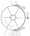
図1は、入口3及び出口4を有するアイロナーベッド2に対して矢印Pによって示される方向に回転することができるアイロンがけローラー1を備える、回転アイロナーの半径方向断面図を示す。好ましくは、アイロナーベッドは可撓性であり、所定の力によって押圧されてアイロンがけローラーと当接する。そのようなアイロナーベッドは、可撓性アイロナーベッドと呼ばれる。アイロンがけされる衣服は、図示されていないコンベヤーベルトによって入口3において導入されて出口4において排出される。衣服は、アイロンがけローラー1とアイロナーベッド2との間に位置する間、アイロナーベッドによって加熱され、衣服の水分がアイロンがけローラー1の表面にある多数の小さい穴を通って蒸発するようにする。アイロナーベッド2は、全体的に5で示されるヒートチャンバーを有する。このヒートチャンバーは、いわゆるディンプルプレート6と、アイロンがけローラーに向かって面するアイロンがけ面8であるアイロンがけプレート7との間に画定される。図1は、通常は蒸気であるが、何らかの他の熱伝達流体、例えば熱水又は伝熱油であってもよい熱媒体の供給管9、10も示す。熱媒体が飽和蒸気である場合、生成される復水がアイロナーベッドの底部11において排出される。ヒートチャンバー5の提供は以下の図面からより明らかになる。
FIG. 1 shows a radial cross-section of a rotating ironer comprising an
図2及び図3に関して、まず、そのようなアイロナーベッドが通常はどのように作製されるのかを記載する。 2 and 3, it will first be described how such an ironer bed is usually made.
図2は、図1によるアイロナーベッド2の表面の一セクションを外側から見て示す。図2では、アイロナーベッドはその平面的な状態に開かれているが、現実的なシナリオでは、アイロナーベッドの2つのプレートが接合されて平面になり、その後、このように作られたサンドイッチ構成がロール巻きにされて図1から分かるようなその湾曲した形状になる。図3は、平面的なアイロナーベッドの、図2の線E−Eに沿った断面を示す。ここでもまた、図1からのアイロンがけプレート7、アイロンがけ面8、ヒートチャンバー5及びディンプルプレート6が分かる。
FIG. 2 shows a section of the surface of the
図3は、アイロナーベッド及びアイロナーローラー1の、2つの軸方向断面E−E及びF−Fをそれぞれ示す。ローラープレート12からなるローラーの最内部が複数の穴13を有することが分かり、複数の穴13を通ってアイロンがけされる布から蒸発した水が吸い出され得る。ローラー12には、大抵の場合に、ばね14からなる弾性巻線と、ばね14の上部の2層のフェルトとが取り付けられる。さらに、アイロンがけされる衣服16のアイテムが示されており、アイロンがけプレート7とフェルト15との間にきつく挟まれている。
FIG. 3 shows two axial sections EE and FF of the ironer bed and
アイロナーベッドを製造するさらなる既知の方法を利用可能である。最も一般的に使用される方法は、比較的厚いプレート(可能性としてはアイロンがけプレート)の上部に配置される、平面的で比較的薄いプレート(可能性としてはディンプルプレート)から開始し、次いでこれらのプレートを、複数の可能な方法のうちの1つによって接合することである。最も多くは、ディンプルプレート6とアイロナープレート7との間に、例えば図2に示すようなパターンで溶接を行う。まず、溶接の継目はアイロナーベッドの軸方向縁に沿う長手方向に延在する継目S1、S2を有し、多数の溶接点P1、P2…PNが設けられる。溶接点P1及びP2は図3に示されている。全ての溶接部が作られると、溶接部P1、P2…PN間でディンプルプレートが膨出するような高圧で、ディンプルプレートとアイロンがけプレートとの間に圧力媒体を導入し、それによってヒートチャンバー5が設けられる。ヒートチャンバー5は、供給管9、10から出口11への熱媒体の流れを制御する目的で異なるパターンで設けられ、その結果、動作時に、アイロナーベッドが可能な最も均一な温度分布を得る。温度分布をさらに制御するために、それ自体が既知の方法で溶接の継目S3、S4をさらに導入することが可能である。流れを方向付ける別の方法は、溶接部間の点の距離d1及びd2をそれぞれ変えることによる、アーチ状部分の盛り上がり(arch rise)h1及びh2のそれぞれの変化、したがって流れ断面の変化によって達成することができ、これは図2、及び図3のそれぞれ2つの断面E及びFで示されている。
Further known methods of manufacturing ironer beds are available. The most commonly used method starts with a flat, relatively thin plate (possibly a dimple plate) placed on top of a relatively thick plate (possibly an ironing plate), then These plates are joined by one of several possible methods. In most cases, welding is performed between the
図3は、網掛けによって、点溶接である点P2の溶接部を示す。長手方向に延在する溶接の継目S1及びS2は好ましくは、連続的なローラー溶接によって作られる。 FIG. 3 shows a welded portion of the point P2 which is spot welding by shading. The weld seams S1 and S2 extending in the longitudinal direction are preferably made by continuous roller welding.
次に、平面的なアイロナーベッドをアイロナーローラー1の周りに適合するように巻き付けることができるが、他の既知の方法も存在する。ディンプルプレートの成形は、好ましくは巻き付けた後でブロー成形によって達成されるが、接合する前にディンプルプレートをエンボス加工し、ディンプルプレートが溶接によってアイロンがけプレートに接合される前にヒートチャンバーが既に設けられているようにすることも可能である。また、溶接方法は異なり得る(図4及び図5を参照)。
Next, a planar ironer bed can be wrapped around the
本開示はこれまでのところ従来技術を含むが、本発明は、ディンプルプレート及びアイロンがけプレートの材料の選択に関するものである。したがって、本発明は、アイロナーベッドを接合及び/又は巻付ける方法に限定されない。本発明は、より厚い、あまり耐食性ではないアイロンがけプレートと組み合わせた比較的耐食性のディンプルプレートの選択に専ら関する。 While the present disclosure so far includes prior art, the present invention relates to the selection of dimple plate and ironing plate materials. Therefore, the present invention is not limited to the method of joining and / or winding the ironer bed. The present invention is exclusively concerned with the selection of a relatively corrosive dimple plate in combination with a thicker, less corrosion resistant ironing plate.
本明細書の導入部において、ステンレス鋼及び非ステンレス鋼の使用について既知であることを既に記載した。これまでになされた試みとは対照的に、本発明は、ディンプルプレートよりも比較的さびやすい(less stainless)アイロンがけプレートによって、アイロナーベッドをよりさびないものとすることに関する。ディンプルプレートの引き伸ばしを可能にするために、それはアイロンがけプレートよりも変形するのがはるかに容易でなければならず、これは、実際に、アイロンがけプレートがディンプルプレートよりも厚いことを意味する。これは、アイロンがけプレートにおける熱の均一な分布に関しても特に都合が良い。したがって、本発明は、アイロンがけプレートが比較的厚いことによって、アイロンがけプレートを特にさびないものとして選択する必要がなく、一方で比較的薄いディンプルプレートをさびない材料として選択するという発見に基づく。追加の利点は、フェライト鋼のアイロンがけプレートがステンレス鋼のアイロンがけプレートよりも良好な摺動特性を有するというよく知られた状況である。また、溶接部における腐食攻撃が、母材と熱影響部(HAZ)との間の粒界において、より厚い低合金プレートに向かう方向へ低合金プレート又は非合金プレートに対して直角に広がる傾向があると見出されたことは本発明のさらなる驚くべき利点である。これは、剛性の寄与が、薄いプレートの厚さからなる部分からプレート自体の幅からなる部分まで、実際には無限に剛性である自由縁を閉じるまで変化することを意味する。これは、プレートが曲がっている場合に媒体からの圧力がクラックを開くことを防止する(ある場合)。さらに、2つの材料間の熱膨張係数の差が、構成材料の特性及び製造方法の結果として全ての溶接部の周りに生じるノッチを閉じようとする曲げモーメントを引き起こす。このように、フェライト低合金又は非合金鋼のアイロナーベッドから分かる優れた滑動特性を有する耐食性アイロナーベッドを達成することができる。 In the introductory part of this description it has already been mentioned that the use of stainless steel and non-stainless steel is known. In contrast to attempts made so far, the present invention relates to making ironer beds less rusting by ironing plates that are less stainless than dimple plates. In order to be able to stretch the dimple plate, it must be much easier to deform than the ironing plate, which in fact means that the ironing plate is thicker than the dimple plate. This is also particularly advantageous with regard to the uniform distribution of heat in the ironing plate. Thus, the present invention is based on the discovery that the relatively thick dimple plate is selected as a non-rusting material, while the ironing plate is relatively thick so that it is not necessary to select the ironing plate as particularly non-rusting. An additional advantage is the well-known situation that ferritic ironing plates have better sliding properties than stainless steel ironing plates. Also, corrosion attack in the weld tends to spread at right angles to the low alloy plate or non-alloy plate in the direction toward the thicker low alloy plate at the grain boundary between the base material and the heat affected zone (HAZ). It has been found that there is a further surprising advantage of the present invention. This means that the stiffness contribution varies from the portion consisting of the thickness of the thin plate to the portion consisting of the width of the plate itself, until the free edge, which is actually infinitely rigid, is closed. This prevents pressure from the media from opening the crack (if any) when the plate is bent. Furthermore, the difference in coefficient of thermal expansion between the two materials causes a bending moment that attempts to close the notches that occur around all welds as a result of the properties of the constituent materials and the manufacturing method. Thus, it is possible to achieve a corrosion-resistant ironer bed having excellent sliding characteristics as can be seen from a ferritic low alloy or non-alloy steel ironer bed.
図4はレーザー溶接アイロナーベッドを示し、この場合、溶接部(weld)の耐久性及びディンプルプレートの引き伸ばし中の圧力に従うようになっている直径を有する円に沿ってレーザー溶接部P1、P2が作られる。レーザー溶接部S1及びS2が縁に沿って設けられる。レーザー溶接は、薄い方のプレートの側から行うのが好ましい。 FIG. 4 shows a laser welded ironer bed, where the laser welds P1, P2 are along a circle having a diameter adapted to follow the durability of the weld and the pressure during dimple plate stretching. Made. Laser welds S1 and S2 are provided along the edges. Laser welding is preferably performed from the side of the thinner plate.
図5は、フィラー材料を用いることができるさらなる溶接方法を示す。溶接前に、複数の穴をディンプルプレートに設け、続いて穴あけ部の縁に沿ってフィラー材料を用いて溶接部P1、P2及びS2を達成することができる。 FIG. 5 shows a further welding method in which a filler material can be used. Prior to welding, a plurality of holes can be provided in the dimple plate and subsequently the welds P1, P2 and S2 can be achieved using filler material along the edges of the drilled part.
したがって、多数の溶接方法を利用可能であり、ヒートチャンバーを設けるためのアイロナーベッドの引き伸ばし/エンボス加工の順序に関しても幾つかの選択肢を利用可能である。 Thus, a number of welding methods are available and several options are available regarding the ironer bed stretching / embossing sequence to provide the heat chamber.
図6は、図5の溶接部P1、P2に対応する溶接部P1、P2を施すために同時に複数の穴を作りながら、ディンプルプレート17を最初にエンボス加工して所望の形状にする方法を示す。したがって、溶接部P1、P2は、ディンプルプレート17が成形されるまで達成されない。上記教示によると、溶接部S1は縁に沿って作られる。 FIG. 6 shows a method of embossing the dimple plate 17 first to make a desired shape while simultaneously making a plurality of holes for applying the welds P1, P2 corresponding to the welds P1, P2 of FIG. . Therefore, the welds P1 and P2 are not achieved until the dimple plate 17 is formed. According to the above teachings, the weld S1 is made along the edge.
図7は、同様にアイロンがけプレートに固定する前に作製されるディンプルプレート18を示す。ディンプルプレート18の成形は、ディンプルプレート18が、縁L3においてはんだ付け部L1、L2によってアイロンがけプレート19上にはんだ付けされるのに好適であるように行われる。 FIG. 7 shows the dimple plate 18 which is also produced before being secured to the ironing plate. The dimple plate 18 is formed so that the dimple plate 18 is suitable for being soldered on the ironing plate 19 by the soldering portions L1 and L2 at the edge L3.
ここで最後に、本発明によるプレートの組み合わせの選択に関連する利点をまとめる。 Finally, the advantages associated with the selection of the plate combination according to the invention are summarized.
ステンレス鋼の比較的重厚なアイロンがけプレートは以下の有利な特性を有する。
製造時及び動作時の両方で軸方向に寸法安定性が得られるようなより剛性の構造、
改善された熱分布が達成されるようなより重厚な要素の厚さ、
アイロンがけ面上の良好な摩擦特性、
ディンプルプレートの陰極防食、
圧力及び温度に起因する攻撃前線が(ある場合)、より厚いプレートに向かってそらされるため攻撃前線に関して安定化する。ここで、モーメント荷重が厚い面に対して垂直にではなく該面の平面内で圧力応力を伴う。
A relatively heavy ironing plate of stainless steel has the following advantageous properties:
A more rigid structure that provides dimensional stability in the axial direction during both manufacturing and operation,
A thicker element thickness, such that an improved heat distribution is achieved,
Good friction properties on the ironing surface,
Cathodic protection of dimple plate,
The attack front due to pressure and temperature (if any) stabilizes with respect to the attack front as it is deflected towards a thicker plate. Here, the moment load is accompanied by pressure stress in the plane of the surface, not perpendicular to the thick surface.
比較的より薄いディンプルプレートは、以下の有利な特性を有する。
熱の通路を形成する高い延性、
攻撃的な酸素含有蒸気環境における腐食しにくさ、
外部源からの攻撃に対する陰極防食(ある場合)、
製造プロセスにおけるドウェル時間に関して危機的でない(Non-critical)。
A relatively thinner dimple plate has the following advantageous properties:
High ductility, forming a heat passage
Resistant to corrosion in aggressive oxygen-containing steam environments,
Cathodic protection against attacks from external sources (if any),
Non-critical with respect to dwell time in the manufacturing process.
2つの材料の組み合わせは、以下の有利な特性を有する。
熱膨張係数の差によってノッチ先端を閉じようとする溶接部の周りの圧力差が生じる。
The combination of the two materials has the following advantageous properties:
A difference in thermal expansion coefficient creates a pressure difference around the weld that attempts to close the notch tip.
Claims (12)
前記アイロンがけローラーに向かって面する一方のプレートは非合金鋼又は低合金鋼のプレートであり、前記アイロナーローラーとは反対側に面する第2のプレートは前者の前記一方のプレートよりも薄いステンレス鋼プレートであることを特徴とする、アイロナーベッド。 An ironer bed shaped to partially enclose the ironer roller, comprising a pair of metal plates joined together in two layers by welding so that a passage for the heat medium is provided therebetween ,
One plate facing the ironing roller is a non-alloy steel or low alloy steel plate, and the second plate facing away from the ironer roller is thinner than the former one plate. Ironer bed, characterized by a stainless steel plate.
Applications Claiming Priority (5)
| Application Number | Priority Date | Filing Date | Title |
|---|---|---|---|
| DKPA200801396 | 2008-10-03 | ||
| DKPA200801396 | 2008-10-03 | ||
| DKPA200900186 | 2009-02-06 | ||
| DKPA200900186 | 2009-02-06 | ||
| PCT/DK2009/050261 WO2010037401A1 (en) | 2008-10-03 | 2009-10-02 | An ironer bed |
Publications (2)
| Publication Number | Publication Date |
|---|---|
| JP2012504433A JP2012504433A (en) | 2012-02-23 |
| JP5539366B2 true JP5539366B2 (en) | 2014-07-02 |
Family
ID=41593587
Family Applications (1)
| Application Number | Title | Priority Date | Filing Date |
|---|---|---|---|
| JP2011529449A Active JP5539366B2 (en) | 2008-10-03 | 2009-10-02 | Ironer bed |
Country Status (6)
| Country | Link |
|---|---|
| US (1) | US8561327B2 (en) |
| EP (1) | EP2344693B1 (en) |
| JP (1) | JP5539366B2 (en) |
| DK (1) | DK2344693T3 (en) |
| ES (1) | ES2564786T3 (en) |
| WO (1) | WO2010037401A1 (en) |
Families Citing this family (4)
| Publication number | Priority date | Publication date | Assignee | Title |
|---|---|---|---|---|
| BE1018731A5 (en) * | 2009-04-24 | 2011-07-05 | Lapauw Internat Nv | METHOD FOR MANUFACTURING A STEAM OR LIQUID HEATING TANK FOR A IRONING EQUIPMENT, A STEAM OR LIQUID HEATING TANK AND AN IRON PROVIDED WITH SUCH A TANK. |
| BE1020469A5 (en) * | 2012-02-17 | 2013-11-05 | Laco Machinery N V | FAIRER FOR IRONING. |
| CN103911838A (en) * | 2014-03-24 | 2014-07-09 | 灵山县桂合丝业有限公司 | Channel ironing machine |
| BE1024162B1 (en) * | 2016-06-01 | 2017-11-24 | Texfinity | Cockpit for an industrial ironing device and method for manufacturing it |
Family Cites Families (12)
| Publication number | Priority date | Publication date | Assignee | Title |
|---|---|---|---|---|
| US2038363A (en) * | 1935-03-22 | 1936-04-21 | Borg Warner | Ironing-shoe and method of manufacture thereof |
| GB873881A (en) * | 1959-01-12 | 1961-08-02 | Emile D Hooge S P R L Atel Con | Ironing machines |
| US3516184A (en) * | 1969-03-07 | 1970-06-23 | Mc Graw Edison Co | Flatwork ironer chest |
| BE1005950A3 (en) * | 1992-06-05 | 1994-03-15 | Lapauw Romain | INDUSTRIAL IRONING MACHINE AND THE METHOD OF MANUFACTURING A TUB IN SUCH AN IRONING MACHINE. |
| JPH07148396A (en) * | 1993-08-23 | 1995-06-13 | Rapou Roman | Industrial ironing finishing machine and production of bed for use therein |
| DE19757756A1 (en) | 1996-12-31 | 1998-07-02 | Kannegiesser H Gmbh Co | Mangle with bent steel sheet trough for simultaneous mangling and drying wet washing |
| DK1120488T3 (en) | 2000-01-25 | 2004-03-01 | Kannegiesser Aue Gmbh | Trugrulle |
| FR2805286B1 (en) * | 2000-02-23 | 2002-05-17 | Electrolux Syst Blanchisserie | IRONING DRYER WITH HEATED IRONING CUP AND HEAT FLUID |
| DE50210616D1 (en) * | 2001-02-14 | 2007-09-20 | Kannegiesser Aue Gmbh | ironer |
| US20050115121A1 (en) * | 2001-12-04 | 2005-06-02 | Steen Nielsen | Rotary ironer for ironing essentially rectangular pieces of cloth |
| US6926971B2 (en) * | 2002-06-28 | 2005-08-09 | All-Clad Metalcrafters Llc | Bonded metal components having uniform thermal conductivity characteristics and method of making same |
| DE202004015701U1 (en) | 2004-10-11 | 2005-02-10 | Jensen Denmark A/S | Trough for receiving rectangular washing, e.g. sheets, from a mangle comprises steel plates provided in a region with connections which interrupt a homogeneous pattern to obtain different flow paths for a medium transporting heat |
-
2009
- 2009-10-02 JP JP2011529449A patent/JP5539366B2/en active Active
- 2009-10-02 ES ES09740843.9T patent/ES2564786T3/en active Active
- 2009-10-02 US US13/122,349 patent/US8561327B2/en active Active
- 2009-10-02 DK DK09740843.9T patent/DK2344693T3/en active
- 2009-10-02 EP EP09740843.9A patent/EP2344693B1/en active Active
- 2009-10-02 WO PCT/DK2009/050261 patent/WO2010037401A1/en active Application Filing
Also Published As
| Publication number | Publication date |
|---|---|
| ES2564786T3 (en) | 2016-03-29 |
| DK2344693T3 (en) | 2016-03-21 |
| US20110232140A1 (en) | 2011-09-29 |
| JP2012504433A (en) | 2012-02-23 |
| US8561327B2 (en) | 2013-10-22 |
| WO2010037401A1 (en) | 2010-04-08 |
| EP2344693A1 (en) | 2011-07-20 |
| EP2344693B1 (en) | 2015-12-16 |
Similar Documents
| Publication | Publication Date | Title |
|---|---|---|
| JP5539366B2 (en) | Ironer bed | |
| ATE478185T1 (en) | METHOD FOR REMOVAL OF LINTS FROM A HEAT EXCHANGER OF A DOMESTIC APPLIANCE, AND CORRESPONDING DOMESTIC APPLIANCE | |
| CN109014793B (en) | A kind of manufacturing method of spiral seam thermometal composite welded pipe | |
| KR100737817B1 (en) | Heating roll | |
| US10933342B2 (en) | Heat transfer tube and method for manufacturing a heat transfer tube | |
| RU2007129851A (en) | DRYING CYLINDER | |
| US3118240A (en) | D hooge | |
| EP2243876B1 (en) | Method for manufacturing a bed for an ironing device | |
| CN106436244B (en) | A kind of mixed type slot type press | |
| EP2554741B1 (en) | Bed for ironing device | |
| JP4886267B2 (en) | Belt type roll ironer and tape mark reduction method | |
| KR200454731Y1 (en) | Heated mat | |
| EP2628847A1 (en) | Through for an ironing device | |
| JP2010112663A (en) | Heat exchanger | |
| KR100382120B1 (en) | Method and apparatus for the even heat distribution of heating roll | |
| CN205482528U (en) | Braze reinforcing pad piece of heat exchanger | |
| JP2005511173A (en) | Rotating irona | |
| JP2000176200A (en) | Press iron for clothes-pressing device | |
| JP6153060B2 (en) | Heat exchanger and manufacturing method thereof | |
| KR100349798B1 (en) | a heating roll | |
| JPH1147500A (en) | Cover installed on iron main body or the like of clothes press finishing machine | |
| US3490158A (en) | Unitized dual chamber press head and method of making same | |
| US1837008A (en) | Resilient padding for ironing machines | |
| JP2010112662A (en) | Heat exchanger | |
| EP1767688B1 (en) | Spring pad for an ironing machine |
Legal Events
| Date | Code | Title | Description |
|---|---|---|---|
| RD04 | Notification of resignation of power of attorney |
Free format text: JAPANESE INTERMEDIATE CODE: A7424 Effective date: 20120713 |
|
| A621 | Written request for application examination |
Free format text: JAPANESE INTERMEDIATE CODE: A621 Effective date: 20121002 |
|
| A977 | Report on retrieval |
Free format text: JAPANESE INTERMEDIATE CODE: A971007 Effective date: 20131010 |
|
| A131 | Notification of reasons for refusal |
Free format text: JAPANESE INTERMEDIATE CODE: A131 Effective date: 20131017 |
|
| TRDD | Decision of grant or rejection written | ||
| A01 | Written decision to grant a patent or to grant a registration (utility model) |
Free format text: JAPANESE INTERMEDIATE CODE: A01 Effective date: 20140403 |
|
| R150 | Certificate of patent or registration of utility model |
Ref document number: 5539366 Country of ref document: JP Free format text: JAPANESE INTERMEDIATE CODE: R150 |
|
| A61 | First payment of annual fees (during grant procedure) |
Free format text: JAPANESE INTERMEDIATE CODE: A61 Effective date: 20140430 |
|
| R250 | Receipt of annual fees |
Free format text: JAPANESE INTERMEDIATE CODE: R250 |
|
| R250 | Receipt of annual fees |
Free format text: JAPANESE INTERMEDIATE CODE: R250 |
|
| R250 | Receipt of annual fees |
Free format text: JAPANESE INTERMEDIATE CODE: R250 |
|
| R250 | Receipt of annual fees |
Free format text: JAPANESE INTERMEDIATE CODE: R250 |
|
| R250 | Receipt of annual fees |
Free format text: JAPANESE INTERMEDIATE CODE: R250 |
|
| R250 | Receipt of annual fees |
Free format text: JAPANESE INTERMEDIATE CODE: R250 |
|
| R250 | Receipt of annual fees |
Free format text: JAPANESE INTERMEDIATE CODE: R250 |
|
| R250 | Receipt of annual fees |
Free format text: JAPANESE INTERMEDIATE CODE: R250 |