JP5527969B2 - Image display system and micro optical security system - Google Patents
Image display system and micro optical security system Download PDFInfo
- Publication number
- JP5527969B2 JP5527969B2 JP2008512603A JP2008512603A JP5527969B2 JP 5527969 B2 JP5527969 B2 JP 5527969B2 JP 2008512603 A JP2008512603 A JP 2008512603A JP 2008512603 A JP2008512603 A JP 2008512603A JP 5527969 B2 JP5527969 B2 JP 5527969B2
- Authority
- JP
- Japan
- Prior art keywords
- icon
- image
- imaging system
- array
- elements
- Prior art date
- Legal status (The legal status is an assumption and is not a legal conclusion. Google has not performed a legal analysis and makes no representation as to the accuracy of the status listed.)
- Active
Links
- 230000003287 optical effect Effects 0.000 title claims description 167
- 239000000463 material Substances 0.000 claims description 599
- 239000002131 composite material Substances 0.000 claims description 259
- 238000000576 coating method Methods 0.000 claims description 213
- 239000011248 coating agent Substances 0.000 claims description 185
- 239000000758 substrate Substances 0.000 claims description 109
- 238000000034 method Methods 0.000 claims description 89
- 238000011049 filling Methods 0.000 claims description 66
- 125000006850 spacer group Chemical group 0.000 claims description 56
- 238000007639 printing Methods 0.000 claims description 50
- 238000012634 optical imaging Methods 0.000 claims description 46
- 229910052751 metal Inorganic materials 0.000 claims description 27
- 230000006870 function Effects 0.000 claims description 26
- 239000002184 metal Substances 0.000 claims description 26
- 239000011888 foil Substances 0.000 claims description 20
- 239000007788 liquid Substances 0.000 claims description 20
- 238000003384 imaging method Methods 0.000 claims description 18
- 238000003491 array Methods 0.000 claims description 15
- 230000008859 change Effects 0.000 claims description 13
- 238000004806 packaging method and process Methods 0.000 claims description 13
- 239000007789 gas Substances 0.000 claims description 9
- 230000010287 polarization Effects 0.000 claims description 9
- 238000005530 etching Methods 0.000 claims description 7
- 238000003475 lamination Methods 0.000 claims description 5
- 239000007787 solid Substances 0.000 claims description 5
- 239000004922 lacquer Substances 0.000 claims description 4
- 238000003860 storage Methods 0.000 claims description 3
- 238000007373 indentation Methods 0.000 claims 1
- 239000010410 layer Substances 0.000 description 304
- 230000000694 effects Effects 0.000 description 120
- 230000033001 locomotion Effects 0.000 description 62
- 230000000007 visual effect Effects 0.000 description 40
- 238000005339 levitation Methods 0.000 description 37
- 239000010408 film Substances 0.000 description 35
- 239000000047 product Substances 0.000 description 28
- 230000008901 benefit Effects 0.000 description 27
- 239000012530 fluid Substances 0.000 description 26
- 230000000737 periodic effect Effects 0.000 description 26
- 239000002245 particle Substances 0.000 description 23
- 229920000642 polymer Polymers 0.000 description 23
- 238000013461 design Methods 0.000 description 22
- 238000004519 manufacturing process Methods 0.000 description 22
- 238000007789 sealing Methods 0.000 description 22
- 239000000975 dye Substances 0.000 description 20
- 239000000123 paper Substances 0.000 description 20
- 239000000049 pigment Substances 0.000 description 20
- -1 and processed goods Substances 0.000 description 19
- 239000000976 ink Substances 0.000 description 18
- 239000000843 powder Substances 0.000 description 18
- 230000005855 radiation Effects 0.000 description 17
- PXHVJJICTQNCMI-UHFFFAOYSA-N Nickel Chemical compound [Ni] PXHVJJICTQNCMI-UHFFFAOYSA-N 0.000 description 16
- 229910052782 aluminium Inorganic materials 0.000 description 16
- XAGFODPZIPBFFR-UHFFFAOYSA-N aluminium Chemical compound [Al] XAGFODPZIPBFFR-UHFFFAOYSA-N 0.000 description 16
- PCHJSUWPFVWCPO-UHFFFAOYSA-N gold Chemical compound [Au] PCHJSUWPFVWCPO-UHFFFAOYSA-N 0.000 description 16
- 229910052737 gold Inorganic materials 0.000 description 16
- 239000010931 gold Substances 0.000 description 16
- XLYOFNOQVPJJNP-UHFFFAOYSA-N water Substances O XLYOFNOQVPJJNP-UHFFFAOYSA-N 0.000 description 16
- 238000005286 illumination Methods 0.000 description 15
- 239000000853 adhesive Substances 0.000 description 13
- 230000001070 adhesive effect Effects 0.000 description 13
- 239000003086 colorant Substances 0.000 description 13
- 229920006254 polymer film Polymers 0.000 description 13
- BQCADISMDOOEFD-UHFFFAOYSA-N Silver Chemical compound [Ag] BQCADISMDOOEFD-UHFFFAOYSA-N 0.000 description 11
- 230000008878 coupling Effects 0.000 description 11
- 238000010168 coupling process Methods 0.000 description 11
- 238000005859 coupling reaction Methods 0.000 description 11
- 230000036961 partial effect Effects 0.000 description 11
- 229910052709 silver Inorganic materials 0.000 description 11
- 239000004332 silver Substances 0.000 description 11
- 239000002904 solvent Substances 0.000 description 11
- PEDCQBHIVMGVHV-UHFFFAOYSA-N Glycerine Chemical compound OCC(O)CO PEDCQBHIVMGVHV-UHFFFAOYSA-N 0.000 description 10
- 238000001514 detection method Methods 0.000 description 10
- 238000011161 development Methods 0.000 description 10
- 230000018109 developmental process Effects 0.000 description 10
- 239000011521 glass Substances 0.000 description 10
- 230000000873 masking effect Effects 0.000 description 10
- 229920002120 photoresistant polymer Polymers 0.000 description 10
- 238000006243 chemical reaction Methods 0.000 description 9
- 229920000728 polyester Polymers 0.000 description 9
- 230000007704 transition Effects 0.000 description 9
- GWEVSGVZZGPLCZ-UHFFFAOYSA-N Titan oxide Chemical compound O=[Ti]=O GWEVSGVZZGPLCZ-UHFFFAOYSA-N 0.000 description 8
- 238000007654 immersion Methods 0.000 description 8
- 238000001465 metallisation Methods 0.000 description 8
- 229910052759 nickel Inorganic materials 0.000 description 8
- 238000000059 patterning Methods 0.000 description 8
- 238000005266 casting Methods 0.000 description 7
- 239000011247 coating layer Substances 0.000 description 7
- ZZUFCTLCJUWOSV-UHFFFAOYSA-N furosemide Chemical compound C1=C(Cl)C(S(=O)(=O)N)=CC(C(O)=O)=C1NCC1=CC=CO1 ZZUFCTLCJUWOSV-UHFFFAOYSA-N 0.000 description 7
- 230000001965 increasing effect Effects 0.000 description 7
- 230000002829 reductive effect Effects 0.000 description 7
- 239000011347 resin Substances 0.000 description 7
- 229920005989 resin Polymers 0.000 description 7
- 230000035807 sensation Effects 0.000 description 7
- 239000000126 substance Substances 0.000 description 7
- 230000015572 biosynthetic process Effects 0.000 description 6
- 238000005323 electroforming Methods 0.000 description 6
- 239000000839 emulsion Substances 0.000 description 6
- 239000000945 filler Substances 0.000 description 6
- 239000000696 magnetic material Substances 0.000 description 6
- 239000011022 opal Substances 0.000 description 6
- 239000011049 pearl Substances 0.000 description 6
- 108010010803 Gelatin Proteins 0.000 description 5
- 238000005481 NMR spectroscopy Methods 0.000 description 5
- 239000004820 Pressure-sensitive adhesive Substances 0.000 description 5
- 238000000149 argon plasma sintering Methods 0.000 description 5
- 239000012876 carrier material Substances 0.000 description 5
- 238000004049 embossing Methods 0.000 description 5
- 239000004744 fabric Substances 0.000 description 5
- 239000000499 gel Substances 0.000 description 5
- 239000008273 gelatin Substances 0.000 description 5
- 229920000159 gelatin Polymers 0.000 description 5
- 235000019322 gelatine Nutrition 0.000 description 5
- 235000011852 gelatine desserts Nutrition 0.000 description 5
- 235000011187 glycerol Nutrition 0.000 description 5
- 239000006249 magnetic particle Substances 0.000 description 5
- 229910044991 metal oxide Inorganic materials 0.000 description 5
- 150000004706 metal oxides Chemical class 0.000 description 5
- 239000000203 mixture Substances 0.000 description 5
- 230000002093 peripheral effect Effects 0.000 description 5
- 229920000139 polyethylene terephthalate Polymers 0.000 description 5
- 239000005020 polyethylene terephthalate Substances 0.000 description 5
- 229920000307 polymer substrate Polymers 0.000 description 5
- LFQSCWFLJHTTHZ-UHFFFAOYSA-N Ethanol Chemical compound CCO LFQSCWFLJHTTHZ-UHFFFAOYSA-N 0.000 description 4
- 229920000106 Liquid crystal polymer Polymers 0.000 description 4
- 239000004977 Liquid-crystal polymers (LCPs) Substances 0.000 description 4
- 238000001069 Raman spectroscopy Methods 0.000 description 4
- 229920002472 Starch Polymers 0.000 description 4
- 238000000748 compression moulding Methods 0.000 description 4
- 238000000151 deposition Methods 0.000 description 4
- 239000010432 diamond Substances 0.000 description 4
- 238000010348 incorporation Methods 0.000 description 4
- 238000001746 injection moulding Methods 0.000 description 4
- 239000012939 laminating adhesive Substances 0.000 description 4
- 239000004973 liquid crystal related substance Substances 0.000 description 4
- 238000004020 luminiscence type Methods 0.000 description 4
- 150000002739 metals Chemical class 0.000 description 4
- 230000002265 prevention Effects 0.000 description 4
- 230000008569 process Effects 0.000 description 4
- 239000012857 radioactive material Substances 0.000 description 4
- 238000002310 reflectometry Methods 0.000 description 4
- 239000004065 semiconductor Substances 0.000 description 4
- 238000000926 separation method Methods 0.000 description 4
- 239000008107 starch Substances 0.000 description 4
- 235000019698 starch Nutrition 0.000 description 4
- 238000003856 thermoforming Methods 0.000 description 4
- 239000004408 titanium dioxide Substances 0.000 description 4
- VYZAMTAEIAYCRO-UHFFFAOYSA-N Chromium Chemical compound [Cr] VYZAMTAEIAYCRO-UHFFFAOYSA-N 0.000 description 3
- 239000004743 Polypropylene Substances 0.000 description 3
- 239000011358 absorbing material Substances 0.000 description 3
- 238000010521 absorption reaction Methods 0.000 description 3
- NIXOWILDQLNWCW-UHFFFAOYSA-N acrylic acid group Chemical group C(C=C)(=O)O NIXOWILDQLNWCW-UHFFFAOYSA-N 0.000 description 3
- 229920001222 biopolymer Polymers 0.000 description 3
- 239000006229 carbon black Substances 0.000 description 3
- 238000003486 chemical etching Methods 0.000 description 3
- 238000004040 coloring Methods 0.000 description 3
- 239000013078 crystal Substances 0.000 description 3
- 238000001723 curing Methods 0.000 description 3
- 229910003460 diamond Inorganic materials 0.000 description 3
- 239000006185 dispersion Substances 0.000 description 3
- 238000009826 distribution Methods 0.000 description 3
- 238000005401 electroluminescence Methods 0.000 description 3
- 238000010894 electron beam technology Methods 0.000 description 3
- 239000000835 fiber Substances 0.000 description 3
- 239000002657 fibrous material Substances 0.000 description 3
- 239000007850 fluorescent dye Substances 0.000 description 3
- 230000036541 health Effects 0.000 description 3
- 238000001093 holography Methods 0.000 description 3
- 229910052500 inorganic mineral Inorganic materials 0.000 description 3
- 239000002932 luster Substances 0.000 description 3
- 230000005499 meniscus Effects 0.000 description 3
- 239000011707 mineral Substances 0.000 description 3
- 230000004048 modification Effects 0.000 description 3
- 238000012986 modification Methods 0.000 description 3
- 239000002105 nanoparticle Substances 0.000 description 3
- 239000002071 nanotube Substances 0.000 description 3
- 239000011368 organic material Substances 0.000 description 3
- 239000004038 photonic crystal Substances 0.000 description 3
- 229920001155 polypropylene Polymers 0.000 description 3
- 238000012545 processing Methods 0.000 description 3
- 230000001737 promoting effect Effects 0.000 description 3
- 238000003847 radiation curing Methods 0.000 description 3
- 238000002791 soaking Methods 0.000 description 3
- 238000004544 sputter deposition Methods 0.000 description 3
- 230000003068 static effect Effects 0.000 description 3
- 235000000346 sugar Nutrition 0.000 description 3
- 239000000725 suspension Substances 0.000 description 3
- 239000010409 thin film Substances 0.000 description 3
- 238000012546 transfer Methods 0.000 description 3
- 238000005390 triboluminescence Methods 0.000 description 3
- 239000011165 3D composite Substances 0.000 description 2
- 241001270131 Agaricus moelleri Species 0.000 description 2
- 239000004593 Epoxy Substances 0.000 description 2
- JOYRKODLDBILNP-UHFFFAOYSA-N Ethyl urethane Chemical compound CCOC(N)=O JOYRKODLDBILNP-UHFFFAOYSA-N 0.000 description 2
- UQSXHKLRYXJYBZ-UHFFFAOYSA-N Iron oxide Chemical compound [Fe]=O UQSXHKLRYXJYBZ-UHFFFAOYSA-N 0.000 description 2
- OAICVXFJPJFONN-UHFFFAOYSA-N Phosphorus Chemical compound [P] OAICVXFJPJFONN-UHFFFAOYSA-N 0.000 description 2
- 239000004698 Polyethylene Substances 0.000 description 2
- 239000003570 air Substances 0.000 description 2
- 238000013459 approach Methods 0.000 description 2
- 239000001913 cellulose Substances 0.000 description 2
- 229920002678 cellulose Polymers 0.000 description 2
- 235000010980 cellulose Nutrition 0.000 description 2
- 239000000919 ceramic Substances 0.000 description 2
- 229910052804 chromium Inorganic materials 0.000 description 2
- 239000011651 chromium Substances 0.000 description 2
- 150000001875 compounds Chemical class 0.000 description 2
- 238000005520 cutting process Methods 0.000 description 2
- 230000008021 deposition Effects 0.000 description 2
- 239000003599 detergent Substances 0.000 description 2
- 238000007598 dipping method Methods 0.000 description 2
- 238000006073 displacement reaction Methods 0.000 description 2
- 239000003814 drug Substances 0.000 description 2
- 238000001035 drying Methods 0.000 description 2
- 238000009713 electroplating Methods 0.000 description 2
- 235000019441 ethanol Nutrition 0.000 description 2
- UHESRSKEBRADOO-UHFFFAOYSA-N ethyl carbamate;prop-2-enoic acid Chemical compound OC(=O)C=C.CCOC(N)=O UHESRSKEBRADOO-UHFFFAOYSA-N 0.000 description 2
- 235000013305 food Nutrition 0.000 description 2
- 238000007641 inkjet printing Methods 0.000 description 2
- 238000010884 ion-beam technique Methods 0.000 description 2
- 238000002955 isolation Methods 0.000 description 2
- 238000002372 labelling Methods 0.000 description 2
- 238000010030 laminating Methods 0.000 description 2
- 238000000608 laser ablation Methods 0.000 description 2
- 230000000670 limiting effect Effects 0.000 description 2
- 239000011159 matrix material Substances 0.000 description 2
- 238000005459 micromachining Methods 0.000 description 2
- 238000003801 milling Methods 0.000 description 2
- 238000002156 mixing Methods 0.000 description 2
- 239000000178 monomer Substances 0.000 description 2
- 235000016709 nutrition Nutrition 0.000 description 2
- 230000035764 nutrition Effects 0.000 description 2
- 230000005501 phase interface Effects 0.000 description 2
- 238000001020 plasma etching Methods 0.000 description 2
- 238000005498 polishing Methods 0.000 description 2
- 229920000573 polyethylene Polymers 0.000 description 2
- 239000002861 polymer material Substances 0.000 description 2
- 210000001747 pupil Anatomy 0.000 description 2
- 230000009257 reactivity Effects 0.000 description 2
- 238000006722 reduction reaction Methods 0.000 description 2
- 230000035945 sensitivity Effects 0.000 description 2
- 238000004088 simulation Methods 0.000 description 2
- 238000005507 spraying Methods 0.000 description 2
- 150000008163 sugars Chemical class 0.000 description 2
- 230000008961 swelling Effects 0.000 description 2
- 239000012780 transparent material Substances 0.000 description 2
- 238000007740 vapor deposition Methods 0.000 description 2
- 239000011800 void material Substances 0.000 description 2
- NIXOWILDQLNWCW-UHFFFAOYSA-M Acrylate Chemical compound [O-]C(=O)C=C NIXOWILDQLNWCW-UHFFFAOYSA-M 0.000 description 1
- 229920002799 BoPET Polymers 0.000 description 1
- 208000035985 Body Odor Diseases 0.000 description 1
- 101710158075 Bucky ball Proteins 0.000 description 1
- XMWRBQBLMFGWIX-UHFFFAOYSA-N C60 fullerene Chemical compound C12=C3C(C4=C56)=C7C8=C5C5=C9C%10=C6C6=C4C1=C1C4=C6C6=C%10C%10=C9C9=C%11C5=C8C5=C8C7=C3C3=C7C2=C1C1=C2C4=C6C4=C%10C6=C9C9=C%11C5=C5C8=C3C3=C7C1=C1C2=C4C6=C2C9=C5C3=C12 XMWRBQBLMFGWIX-UHFFFAOYSA-N 0.000 description 1
- 229920000298 Cellophane Polymers 0.000 description 1
- 208000001613 Gambling Diseases 0.000 description 1
- 241001503485 Mammuthus Species 0.000 description 1
- 239000004677 Nylon Substances 0.000 description 1
- 229920001328 Polyvinylidene chloride Polymers 0.000 description 1
- XUIMIQQOPSSXEZ-UHFFFAOYSA-N Silicon Chemical compound [Si] XUIMIQQOPSSXEZ-UHFFFAOYSA-N 0.000 description 1
- 206010040904 Skin odour abnormal Diseases 0.000 description 1
- 241000385223 Villosa iris Species 0.000 description 1
- 240000008042 Zea mays Species 0.000 description 1
- 235000005824 Zea mays ssp. parviglumis Nutrition 0.000 description 1
- 235000002017 Zea mays subsp mays Nutrition 0.000 description 1
- 238000002679 ablation Methods 0.000 description 1
- 230000004913 activation Effects 0.000 description 1
- 239000011149 active material Substances 0.000 description 1
- 230000006978 adaptation Effects 0.000 description 1
- 230000002730 additional effect Effects 0.000 description 1
- 239000012790 adhesive layer Substances 0.000 description 1
- 230000002411 adverse Effects 0.000 description 1
- 230000004075 alteration Effects 0.000 description 1
- 230000001166 anti-perspirative effect Effects 0.000 description 1
- 239000003213 antiperspirant Substances 0.000 description 1
- 201000009310 astigmatism Diseases 0.000 description 1
- 230000002238 attenuated effect Effects 0.000 description 1
- 230000003796 beauty Effects 0.000 description 1
- 235000013361 beverage Nutrition 0.000 description 1
- 239000011230 binding agent Substances 0.000 description 1
- 230000005540 biological transmission Effects 0.000 description 1
- 230000001680 brushing effect Effects 0.000 description 1
- 239000011111 cardboard Substances 0.000 description 1
- 239000003795 chemical substances by application Substances 0.000 description 1
- 238000005229 chemical vapour deposition Methods 0.000 description 1
- 230000001427 coherent effect Effects 0.000 description 1
- 230000001010 compromised effect Effects 0.000 description 1
- 230000001143 conditioned effect Effects 0.000 description 1
- 239000000470 constituent Substances 0.000 description 1
- 235000005822 corn Nutrition 0.000 description 1
- 239000002537 cosmetic Substances 0.000 description 1
- 230000007423 decrease Effects 0.000 description 1
- 230000007123 defense Effects 0.000 description 1
- 238000005137 deposition process Methods 0.000 description 1
- 238000010586 diagram Methods 0.000 description 1
- 238000003618 dip coating Methods 0.000 description 1
- 238000004851 dishwashing Methods 0.000 description 1
- 239000012769 display material Substances 0.000 description 1
- 229940079593 drug Drugs 0.000 description 1
- 238000012377 drug delivery Methods 0.000 description 1
- 229920001971 elastomer Polymers 0.000 description 1
- 239000000806 elastomer Substances 0.000 description 1
- 238000007772 electroless plating Methods 0.000 description 1
- 230000002708 enhancing effect Effects 0.000 description 1
- 230000007717 exclusion Effects 0.000 description 1
- 239000002360 explosive Substances 0.000 description 1
- 238000001125 extrusion Methods 0.000 description 1
- 238000001914 filtration Methods 0.000 description 1
- 239000003205 fragrance Substances 0.000 description 1
- 238000007755 gap coating Methods 0.000 description 1
- 238000007646 gravure printing Methods 0.000 description 1
- 230000037308 hair color Effects 0.000 description 1
- 238000010438 heat treatment Methods 0.000 description 1
- AMGQUBHHOARCQH-UHFFFAOYSA-N indium;oxotin Chemical compound [In].[Sn]=O AMGQUBHHOARCQH-UHFFFAOYSA-N 0.000 description 1
- 238000002347 injection Methods 0.000 description 1
- 239000007924 injection Substances 0.000 description 1
- 239000002648 laminated material Substances 0.000 description 1
- 238000007644 letterpress printing Methods 0.000 description 1
- 238000003754 machining Methods 0.000 description 1
- 230000005415 magnetization Effects 0.000 description 1
- 238000005259 measurement Methods 0.000 description 1
- 239000007769 metal material Substances 0.000 description 1
- 239000002923 metal particle Substances 0.000 description 1
- 238000002493 microarray Methods 0.000 description 1
- 238000001451 molecular beam epitaxy Methods 0.000 description 1
- 238000000465 moulding Methods 0.000 description 1
- 210000003205 muscle Anatomy 0.000 description 1
- ORQBXQOJMQIAOY-UHFFFAOYSA-N nobelium Chemical compound [No] ORQBXQOJMQIAOY-UHFFFAOYSA-N 0.000 description 1
- 229920001778 nylon Polymers 0.000 description 1
- 229910052762 osmium Inorganic materials 0.000 description 1
- SYQBFIAQOQZEGI-UHFFFAOYSA-N osmium atom Chemical compound [Os] SYQBFIAQOQZEGI-UHFFFAOYSA-N 0.000 description 1
- 230000001151 other effect Effects 0.000 description 1
- 230000003647 oxidation Effects 0.000 description 1
- 238000007254 oxidation reaction Methods 0.000 description 1
- TWNQGVIAIRXVLR-UHFFFAOYSA-N oxo(oxoalumanyloxy)alumane Chemical compound O=[Al]O[Al]=O TWNQGVIAIRXVLR-UHFFFAOYSA-N 0.000 description 1
- 239000003973 paint Substances 0.000 description 1
- 239000011087 paperboard Substances 0.000 description 1
- 238000007540 photo-reduction reaction Methods 0.000 description 1
- 230000000704 physical effect Effects 0.000 description 1
- 239000004033 plastic Substances 0.000 description 1
- 229920003023 plastic Polymers 0.000 description 1
- 238000007747 plating Methods 0.000 description 1
- 229920000515 polycarbonate Polymers 0.000 description 1
- 239000004417 polycarbonate Substances 0.000 description 1
- 229920006267 polyester film Polymers 0.000 description 1
- 238000006116 polymerization reaction Methods 0.000 description 1
- 239000005033 polyvinylidene chloride Substances 0.000 description 1
- 239000000955 prescription drug Substances 0.000 description 1
- 230000001681 protective effect Effects 0.000 description 1
- 230000009467 reduction Effects 0.000 description 1
- 230000003252 repetitive effect Effects 0.000 description 1
- 230000010076 replication Effects 0.000 description 1
- 230000033458 reproduction Effects 0.000 description 1
- 238000012552 review Methods 0.000 description 1
- 229910052703 rhodium Inorganic materials 0.000 description 1
- 239000010948 rhodium Substances 0.000 description 1
- MHOVAHRLVXNVSD-UHFFFAOYSA-N rhodium atom Chemical compound [Rh] MHOVAHRLVXNVSD-UHFFFAOYSA-N 0.000 description 1
- 238000005070 sampling Methods 0.000 description 1
- 229920006298 saran Polymers 0.000 description 1
- 238000007790 scraping Methods 0.000 description 1
- 238000013515 script Methods 0.000 description 1
- 229910052710 silicon Inorganic materials 0.000 description 1
- 239000010703 silicon Substances 0.000 description 1
- 239000002356 single layer Substances 0.000 description 1
- 238000004513 sizing Methods 0.000 description 1
- 238000007711 solidification Methods 0.000 description 1
- 230000008023 solidification Effects 0.000 description 1
- 230000003595 spectral effect Effects 0.000 description 1
- 238000001228 spectrum Methods 0.000 description 1
- 238000004528 spin coating Methods 0.000 description 1
- 239000007921 spray Substances 0.000 description 1
- 238000010561 standard procedure Methods 0.000 description 1
- 238000000859 sublimation Methods 0.000 description 1
- 230000008022 sublimation Effects 0.000 description 1
- 239000013589 supplement Substances 0.000 description 1
- 229920002994 synthetic fiber Polymers 0.000 description 1
- 239000006188 syrup Substances 0.000 description 1
- 235000020357 syrup Nutrition 0.000 description 1
- 239000004753 textile Substances 0.000 description 1
- 229920001187 thermosetting polymer Polymers 0.000 description 1
- 239000004634 thermosetting polymer Substances 0.000 description 1
- 235000019505 tobacco product Nutrition 0.000 description 1
- 230000009466 transformation Effects 0.000 description 1
- JFALSRSLKYAFGM-UHFFFAOYSA-N uranium(0) Chemical compound [U] JFALSRSLKYAFGM-UHFFFAOYSA-N 0.000 description 1
- 238000001771 vacuum deposition Methods 0.000 description 1
- 239000002966 varnish Substances 0.000 description 1
- 238000012795 verification Methods 0.000 description 1
- 229920002554 vinyl polymer Polymers 0.000 description 1
- 239000011782 vitamin Substances 0.000 description 1
- 229940088594 vitamin Drugs 0.000 description 1
- 229930003231 vitamin Natural products 0.000 description 1
- 235000013343 vitamin Nutrition 0.000 description 1
Images


Classifications
-
- B—PERFORMING OPERATIONS; TRANSPORTING
- B42—BOOKBINDING; ALBUMS; FILES; SPECIAL PRINTED MATTER
- B42D—BOOKS; BOOK COVERS; LOOSE LEAVES; PRINTED MATTER CHARACTERISED BY IDENTIFICATION OR SECURITY FEATURES; PRINTED MATTER OF SPECIAL FORMAT OR STYLE NOT OTHERWISE PROVIDED FOR; DEVICES FOR USE THEREWITH AND NOT OTHERWISE PROVIDED FOR; MOVABLE-STRIP WRITING OR READING APPARATUS
- B42D25/00—Information-bearing cards or sheet-like structures characterised by identification or security features; Manufacture thereof
- B42D25/30—Identification or security features, e.g. for preventing forgery
- B42D25/324—Reliefs
-
- G—PHYSICS
- G02—OPTICS
- G02B—OPTICAL ELEMENTS, SYSTEMS OR APPARATUS
- G02B27/00—Optical systems or apparatus not provided for by any of the groups G02B1/00 - G02B26/00, G02B30/00
- G02B27/10—Beam splitting or combining systems
-
- B—PERFORMING OPERATIONS; TRANSPORTING
- B42—BOOKBINDING; ALBUMS; FILES; SPECIAL PRINTED MATTER
- B42D—BOOKS; BOOK COVERS; LOOSE LEAVES; PRINTED MATTER CHARACTERISED BY IDENTIFICATION OR SECURITY FEATURES; PRINTED MATTER OF SPECIAL FORMAT OR STYLE NOT OTHERWISE PROVIDED FOR; DEVICES FOR USE THEREWITH AND NOT OTHERWISE PROVIDED FOR; MOVABLE-STRIP WRITING OR READING APPARATUS
- B42D25/00—Information-bearing cards or sheet-like structures characterised by identification or security features; Manufacture thereof
- B42D25/20—Information-bearing cards or sheet-like structures characterised by identification or security features; Manufacture thereof characterised by a particular use or purpose
- B42D25/29—Securities; Bank notes
-
- B—PERFORMING OPERATIONS; TRANSPORTING
- B42—BOOKBINDING; ALBUMS; FILES; SPECIAL PRINTED MATTER
- B42D—BOOKS; BOOK COVERS; LOOSE LEAVES; PRINTED MATTER CHARACTERISED BY IDENTIFICATION OR SECURITY FEATURES; PRINTED MATTER OF SPECIAL FORMAT OR STYLE NOT OTHERWISE PROVIDED FOR; DEVICES FOR USE THEREWITH AND NOT OTHERWISE PROVIDED FOR; MOVABLE-STRIP WRITING OR READING APPARATUS
- B42D25/00—Information-bearing cards or sheet-like structures characterised by identification or security features; Manufacture thereof
- B42D25/30—Identification or security features, e.g. for preventing forgery
- B42D25/328—Diffraction gratings; Holograms
-
- B—PERFORMING OPERATIONS; TRANSPORTING
- B42—BOOKBINDING; ALBUMS; FILES; SPECIAL PRINTED MATTER
- B42D—BOOKS; BOOK COVERS; LOOSE LEAVES; PRINTED MATTER CHARACTERISED BY IDENTIFICATION OR SECURITY FEATURES; PRINTED MATTER OF SPECIAL FORMAT OR STYLE NOT OTHERWISE PROVIDED FOR; DEVICES FOR USE THEREWITH AND NOT OTHERWISE PROVIDED FOR; MOVABLE-STRIP WRITING OR READING APPARATUS
- B42D25/00—Information-bearing cards or sheet-like structures characterised by identification or security features; Manufacture thereof
- B42D25/30—Identification or security features, e.g. for preventing forgery
- B42D25/342—Moiré effects
-
- B—PERFORMING OPERATIONS; TRANSPORTING
- B42—BOOKBINDING; ALBUMS; FILES; SPECIAL PRINTED MATTER
- B42D—BOOKS; BOOK COVERS; LOOSE LEAVES; PRINTED MATTER CHARACTERISED BY IDENTIFICATION OR SECURITY FEATURES; PRINTED MATTER OF SPECIAL FORMAT OR STYLE NOT OTHERWISE PROVIDED FOR; DEVICES FOR USE THEREWITH AND NOT OTHERWISE PROVIDED FOR; MOVABLE-STRIP WRITING OR READING APPARATUS
- B42D25/00—Information-bearing cards or sheet-like structures characterised by identification or security features; Manufacture thereof
- B42D25/30—Identification or security features, e.g. for preventing forgery
- B42D25/351—Translucent or partly translucent parts, e.g. windows
-
- B—PERFORMING OPERATIONS; TRANSPORTING
- B42—BOOKBINDING; ALBUMS; FILES; SPECIAL PRINTED MATTER
- B42D—BOOKS; BOOK COVERS; LOOSE LEAVES; PRINTED MATTER CHARACTERISED BY IDENTIFICATION OR SECURITY FEATURES; PRINTED MATTER OF SPECIAL FORMAT OR STYLE NOT OTHERWISE PROVIDED FOR; DEVICES FOR USE THEREWITH AND NOT OTHERWISE PROVIDED FOR; MOVABLE-STRIP WRITING OR READING APPARATUS
- B42D25/00—Information-bearing cards or sheet-like structures characterised by identification or security features; Manufacture thereof
- B42D25/30—Identification or security features, e.g. for preventing forgery
- B42D25/355—Security threads
-
- B—PERFORMING OPERATIONS; TRANSPORTING
- B42—BOOKBINDING; ALBUMS; FILES; SPECIAL PRINTED MATTER
- B42D—BOOKS; BOOK COVERS; LOOSE LEAVES; PRINTED MATTER CHARACTERISED BY IDENTIFICATION OR SECURITY FEATURES; PRINTED MATTER OF SPECIAL FORMAT OR STYLE NOT OTHERWISE PROVIDED FOR; DEVICES FOR USE THEREWITH AND NOT OTHERWISE PROVIDED FOR; MOVABLE-STRIP WRITING OR READING APPARATUS
- B42D25/00—Information-bearing cards or sheet-like structures characterised by identification or security features; Manufacture thereof
- B42D25/30—Identification or security features, e.g. for preventing forgery
- B42D25/36—Identification or security features, e.g. for preventing forgery comprising special materials
- B42D25/369—Magnetised or magnetisable materials
-
- B—PERFORMING OPERATIONS; TRANSPORTING
- B42—BOOKBINDING; ALBUMS; FILES; SPECIAL PRINTED MATTER
- B42D—BOOKS; BOOK COVERS; LOOSE LEAVES; PRINTED MATTER CHARACTERISED BY IDENTIFICATION OR SECURITY FEATURES; PRINTED MATTER OF SPECIAL FORMAT OR STYLE NOT OTHERWISE PROVIDED FOR; DEVICES FOR USE THEREWITH AND NOT OTHERWISE PROVIDED FOR; MOVABLE-STRIP WRITING OR READING APPARATUS
- B42D25/00—Information-bearing cards or sheet-like structures characterised by identification or security features; Manufacture thereof
- B42D25/30—Identification or security features, e.g. for preventing forgery
- B42D25/36—Identification or security features, e.g. for preventing forgery comprising special materials
- B42D25/373—Metallic materials
-
- B—PERFORMING OPERATIONS; TRANSPORTING
- B42—BOOKBINDING; ALBUMS; FILES; SPECIAL PRINTED MATTER
- B42D—BOOKS; BOOK COVERS; LOOSE LEAVES; PRINTED MATTER CHARACTERISED BY IDENTIFICATION OR SECURITY FEATURES; PRINTED MATTER OF SPECIAL FORMAT OR STYLE NOT OTHERWISE PROVIDED FOR; DEVICES FOR USE THEREWITH AND NOT OTHERWISE PROVIDED FOR; MOVABLE-STRIP WRITING OR READING APPARATUS
- B42D25/00—Information-bearing cards or sheet-like structures characterised by identification or security features; Manufacture thereof
- B42D25/30—Identification or security features, e.g. for preventing forgery
- B42D25/36—Identification or security features, e.g. for preventing forgery comprising special materials
- B42D25/378—Special inks
- B42D25/391—Special inks absorbing or reflecting polarised light
-
- B—PERFORMING OPERATIONS; TRANSPORTING
- B42—BOOKBINDING; ALBUMS; FILES; SPECIAL PRINTED MATTER
- B42D—BOOKS; BOOK COVERS; LOOSE LEAVES; PRINTED MATTER CHARACTERISED BY IDENTIFICATION OR SECURITY FEATURES; PRINTED MATTER OF SPECIAL FORMAT OR STYLE NOT OTHERWISE PROVIDED FOR; DEVICES FOR USE THEREWITH AND NOT OTHERWISE PROVIDED FOR; MOVABLE-STRIP WRITING OR READING APPARATUS
- B42D25/00—Information-bearing cards or sheet-like structures characterised by identification or security features; Manufacture thereof
- B42D25/40—Manufacture
- B42D25/405—Marking
- B42D25/425—Marking by deformation, e.g. embossing
-
- B—PERFORMING OPERATIONS; TRANSPORTING
- B42—BOOKBINDING; ALBUMS; FILES; SPECIAL PRINTED MATTER
- B42D—BOOKS; BOOK COVERS; LOOSE LEAVES; PRINTED MATTER CHARACTERISED BY IDENTIFICATION OR SECURITY FEATURES; PRINTED MATTER OF SPECIAL FORMAT OR STYLE NOT OTHERWISE PROVIDED FOR; DEVICES FOR USE THEREWITH AND NOT OTHERWISE PROVIDED FOR; MOVABLE-STRIP WRITING OR READING APPARATUS
- B42D25/00—Information-bearing cards or sheet-like structures characterised by identification or security features; Manufacture thereof
- B42D25/40—Manufacture
- B42D25/405—Marking
- B42D25/43—Marking by removal of material
-
- G—PHYSICS
- G02—OPTICS
- G02B—OPTICAL ELEMENTS, SYSTEMS OR APPARATUS
- G02B30/00—Optical systems or apparatus for producing three-dimensional [3D] effects, e.g. stereoscopic images
- G02B30/20—Optical systems or apparatus for producing three-dimensional [3D] effects, e.g. stereoscopic images by providing first and second parallax images to an observer's left and right eyes
- G02B30/26—Optical systems or apparatus for producing three-dimensional [3D] effects, e.g. stereoscopic images by providing first and second parallax images to an observer's left and right eyes of the autostereoscopic type
- G02B30/27—Optical systems or apparatus for producing three-dimensional [3D] effects, e.g. stereoscopic images by providing first and second parallax images to an observer's left and right eyes of the autostereoscopic type involving lenticular arrays
-
- G—PHYSICS
- G03—PHOTOGRAPHY; CINEMATOGRAPHY; ANALOGOUS TECHNIQUES USING WAVES OTHER THAN OPTICAL WAVES; ELECTROGRAPHY; HOLOGRAPHY
- G03H—HOLOGRAPHIC PROCESSES OR APPARATUS
- G03H1/00—Holographic processes or apparatus using light, infrared or ultraviolet waves for obtaining holograms or for obtaining an image from them; Details peculiar thereto
- G03H1/02—Details of features involved during the holographic process; Replication of holograms without interference recording
- G03H1/024—Hologram nature or properties
- G03H1/0244—Surface relief holograms
-
- B42D2033/10—
-
- B42D2033/16—
-
- B42D2033/18—
-
- B42D2033/20—
-
- B42D2033/24—
-
- B42D2035/08—
-
- B42D2035/20—
-
- B42D2035/26—
-
- B42D2035/36—
-
- B42D2035/44—
-
- B—PERFORMING OPERATIONS; TRANSPORTING
- B42—BOOKBINDING; ALBUMS; FILES; SPECIAL PRINTED MATTER
- B42D—BOOKS; BOOK COVERS; LOOSE LEAVES; PRINTED MATTER CHARACTERISED BY IDENTIFICATION OR SECURITY FEATURES; PRINTED MATTER OF SPECIAL FORMAT OR STYLE NOT OTHERWISE PROVIDED FOR; DEVICES FOR USE THEREWITH AND NOT OTHERWISE PROVIDED FOR; MOVABLE-STRIP WRITING OR READING APPARATUS
- B42D25/00—Information-bearing cards or sheet-like structures characterised by identification or security features; Manufacture thereof
- B42D25/30—Identification or security features, e.g. for preventing forgery
- B42D25/36—Identification or security features, e.g. for preventing forgery comprising special materials
- B42D25/378—Special inks
- B42D25/382—Special inks absorbing or reflecting infrared light
-
- B—PERFORMING OPERATIONS; TRANSPORTING
- B42—BOOKBINDING; ALBUMS; FILES; SPECIAL PRINTED MATTER
- B42D—BOOKS; BOOK COVERS; LOOSE LEAVES; PRINTED MATTER CHARACTERISED BY IDENTIFICATION OR SECURITY FEATURES; PRINTED MATTER OF SPECIAL FORMAT OR STYLE NOT OTHERWISE PROVIDED FOR; DEVICES FOR USE THEREWITH AND NOT OTHERWISE PROVIDED FOR; MOVABLE-STRIP WRITING OR READING APPARATUS
- B42D25/00—Information-bearing cards or sheet-like structures characterised by identification or security features; Manufacture thereof
- B42D25/30—Identification or security features, e.g. for preventing forgery
- B42D25/36—Identification or security features, e.g. for preventing forgery comprising special materials
- B42D25/378—Special inks
- B42D25/387—Special inks absorbing or reflecting ultraviolet light
Landscapes
- Physics & Mathematics (AREA)
- General Physics & Mathematics (AREA)
- Engineering & Computer Science (AREA)
- Manufacturing & Machinery (AREA)
- Optics & Photonics (AREA)
- Business, Economics & Management (AREA)
- Accounting & Taxation (AREA)
- Finance (AREA)
- Credit Cards Or The Like (AREA)
- Photosensitive Polymer And Photoresist Processing (AREA)
- Casting Or Compression Moulding Of Plastics Or The Like (AREA)
- Heating, Cooling, Or Curing Plastics Or The Like In General (AREA)
- Stereoscopic And Panoramic Photography (AREA)
- Printing Methods (AREA)
- Microscoopes, Condenser (AREA)
- Lenses (AREA)
Description
(関連出願の相互参照)
本願は、2005年5月18日出願の米国仮特許出願番号第60/682,231号、及び2005年5月20日出願の米国仮特許出願番号第60/683,037号の利点及びそれらに対する優先権を主張しており、それぞれを全体として参照することにより本明細書に援用する。
(Cross-reference of related applications)
The present application is directed to and advantages of US Provisional Patent Application No. 60 / 682,231 filed May 18, 2005 and US Provisional Patent Application No. 60 / 683,037 filed May 20, 2005. Priorities are claimed and each is incorporated herein by reference in its entirety.
本発明は、例示的な実施形態においては、ポリマーフィルム内の微細構造アイコン要素から形成される、画像表示システムに関する。
本発明はまた、例示的な実施形態では高分子フィルムとして形成される合成倍率マイクロ光学システムに関する。本開示の多様な実施形態により提供される優れた効果は、製品、包装、印刷物及び消費物質の視覚的な機能強化だけではなく、貨幣、文書及び製品の、公然及び秘密の認証のためのセキュリティ手段としても使用できる。
The present invention relates in an exemplary embodiment to an image display system formed from microstructured icon elements in a polymer film.
The present invention also relates to a synthetic magnification micro-optic system, which in an exemplary embodiment is formed as a polymer film. The superior effects provided by the various embodiments of the present disclosure not only enhance the visual enhancement of products, packaging, printed materials and consumer substances, but also security for open and confidential authentication of money, documents and products. It can also be used as a means.
多様な画像表示システムがこれまでに試みられている。典型的な画像表示システムは、従来の印刷技術を用いる。いくつかの画像表示システムは、ホログラフィック画像表示および/もしくはエンボス画像特徴を含む。これらのシステムは全て、表示される画像の性質または品質に関して欠点を有する。より具体的には、これらは全て、容易にコピーでき、したがって認証またはセキュリティ装置として機能しないという不利点を有する。 Various image display systems have been tried so far. A typical image display system uses conventional printing techniques. Some image display systems include holographic image display and / or embossed image features. All these systems have drawbacks regarding the nature or quality of the displayed image. More specifically, they all have the disadvantage that they can be easily copied and therefore do not function as an authentication or security device.
貨幣と文書の認証のための画像システムを提供し、偽の製品を識別し、偽の製品から真正商品を区別するために、及び製造された製品と包装の視覚的な機能強化を提供するために、多様な光学材料が使用されてきた。これらの例は、ホログラフィックディスプレイ、及びレンズ状の構造と球形のマイクロレンズのアレイを含む他の画像システムを含む。ホログラフィックディスプレイはクレジットカード、運転免許証、及び衣料品のタグとともに使用するために普及してきた。 To provide an imaging system for money and document authentication, to identify fake products, to distinguish genuine products from fake products, and to provide visual enhancements to manufactured products and packaging In addition, various optical materials have been used. Examples include holographic displays and other imaging systems that include an array of lenticular structures and spherical microlenses. Holographic displays have become popular for use with credit cards, driver's licenses, and clothing tags.
文書のセキュリティのためのレンズ状構造の例は、偽装防止手段を提供するために文書の中に埋め込むためのセキュリティスレッドに関するKauleらの米国特許第4,892,336号に開示されている。セキュリティスレッドは透明であり、片面に印刷パターンを、反対側の面に該印刷パターンと対応するレンズ状構造を有している。前記レンズ状構造は複数の平行なシリンダレンズ、あるいは代わりに球形のまたはハチの巣状のレンズから構成されるとして記載されている。 An example of a lenticular structure for document security is disclosed in US Pat. No. 4,892,336 to Kaule et al. Relating to a security thread for embedding in a document to provide anti-counterfeiting means. The security thread is transparent and has a printed pattern on one side and a lens-like structure corresponding to the printed pattern on the opposite side. The lenticular structure is described as being composed of a plurality of parallel cylinder lenses, or alternatively a spherical or honeycomb lens.
Drinkwaterらに対する米国特許第5,712,731号は、実質的に球状のマイクロレンズのアレイと結合されたマイクロ画像のアレイを含むセキュリティ手段を開示している。前記レンズは非点収差レンズであってもよい。前記レンズはそれぞれ通常50から250μmであり、焦点距離は通常200μmである。 US Pat. No. 5,712,731 to Drinkwater et al. Discloses a security measure that includes an array of micro-images combined with an array of substantially spherical microlenses. The lens may be an astigmatism lens. Each of the lenses is usually 50 to 250 μm and the focal length is usually 200 μm.
これらの手法は類似した欠点を有している。それらは、特に文書の認証のために使用するには適していない相対的に厚い構造を生じさせる。円柱レンズまたは球面レンズの使用は狭い視野を提供し、結果としてファジー画像を生じさせ、関連画像に対してレンズの焦点の厳密且つ困難な位置合わせを必要とする。さらに、それらはセキュリティ手段または偽造防止手段として特に効果的であると判明していない。 These approaches have similar drawbacks. They produce relatively thick structures that are not particularly suitable for use for document authentication. The use of a cylindrical or spherical lens provides a narrow field of view, resulting in a fuzzy image, requiring exact and difficult alignment of the lens focus with respect to the associated image. Furthermore, they have not proved particularly effective as security measures or anti-counterfeiting measures.
これらの及び他の欠点を考慮して、当業界には、貨幣、文書、加工品及び製品の明示的な認証を容易にできる安全且つ視覚的に一意の光学材料、及び加工品、製品及び包装の視覚的な機能強化を提供する光学材料に対するニーズが存在する。 In view of these and other shortcomings, the industry has a safe and visually unique optical material that facilitates the explicit authentication of money, documents, processed goods and products, and processed goods, products and packaging. There is a need for optical materials that provide visual enhancements.
本開示は、マイクロ(微細)画像表示システムなどの画像表示システムに関する。例えば、1つの形態において、以下に説明されるような、集光素子のアレイと、微細構造アイコン要素のアレイまたはパターンを含みまたはこれらから形成される画像システムとを含む合成光学画像システムを提供することができ、微細構造アイコン要素は、集合的に画像またはある所望の情報を形成するよう設計され、集光素子のアレイと画像システムは、例えば光学的結合により連携して、画像が任意選択的に拡大されうる合成光学画像を形成する。他の形態において、以下に説明されるような、微細構造アイコン要素のアレイまたはパターンを含むか、またはこれらから形成される画像表示システムが提供され、微細構造アイコン要素は集合的に画像またはある選択された情報を形成するように設計され、画像システムは独立して構成され、画像システムとは別に提供される拡大鏡または顕微鏡などの拡大装置の使用によって画像が見られるか、または情報が読み取られるように設計される。 The present disclosure relates to an image display system such as a micro image display system. For example, in one form, a composite optical imaging system is provided that includes an array of light collection elements and an imaging system that includes or is formed from an array or pattern of microstructured icon elements, as described below. The microstructured icon elements can be designed to collectively form an image or some desired information, and the array of light collecting elements and the image system can be coordinated, for example by optical coupling, so that the image is optional To form a composite optical image that can be magnified. In another form, an image display system is provided that includes or is formed of an array or pattern of microstructured icon elements, as described below, wherein the microstructured icon elements are collectively images or certain selections. The image system is configured independently and the image is viewed or read by using a magnifying device such as a magnifier or microscope provided separately from the image system Designed as such.
本開示はまた、アイコンと呼ばれているマイクロ画像を拡大するための、及び多数の個別のレンズ/アイコン画像システムの統合された性能を通して合成拡大された画像を形成するための、非円柱レンズの規則正しい二次元アレイを利用するフィルム材料に関する。合成拡大された画像及びそれらを取り囲む背景は無色または着色(カラー)のどちらであってもよく、画像及びそれらを取り囲む背景のどちらかまたは両方が、透明、半透明、色素性、蛍光性、燐光性、表示光学可変色、金属化された、あるいは実質的に再帰反射性であってよい。カラー画像を透明な背景または薄い色の付いた背景に表示する材料は、下層に埋め込まれた印刷情報と組み合わせて使用するために特に適している。一つのこのような材料が印刷情報の上に適用されているとき、印刷情報と画像の両方ともが、互いの空間的な、または動的運動(モーション)との関係で同時に視認されることができる。この種の材料は刷り重ねる、つまり印刷を材料の最上の(レンズ)表面に適用することもできる。代わりに(白と黒を含む任意の色の)カラー画像を別の色の半透明または実質的に不透明な背景の上に表示する材料は、下に埋め込まれた印刷情報と組み合わせてではなく、単独で使用するか、または刷り重ねられた情報とともに使用するために特によく適している。 The present disclosure also provides a non-cylindrical lens for magnifying micro images called icons and for forming composite magnified images through the integrated performance of multiple individual lens / icon image systems. The present invention relates to a film material that utilizes a regular two-dimensional array. The composite magnified images and the background surrounding them may be either colorless or colored (color), and either or both of the images and the surrounding background are transparent, translucent, pigmented, fluorescent, phosphorescent , Display optically variable color, metallized, or substantially retroreflective. Materials that display a color image on a transparent background or light colored background are particularly suitable for use in combination with printed information embedded in the underlying layer. When one such material is applied over the print information, both the print information and the image can be viewed simultaneously in relation to each other's spatial or dynamic motion (motion). it can. This type of material can also be overprinted, i.e. printing can be applied to the top (lens) surface of the material. Instead, a material that displays a color image (of any color, including white and black) on a translucent or substantially opaque background of another color, not in combination with the underlying print information, It is particularly well suited for use alone or with overprinted information.
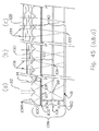
達成される合成拡大(倍率)の規模は、レンズアレイの対称軸とアイコンアレイの対称軸間の「ねじれ(skew)」の程度を含む、多くの因子の選択により制御できる。規則正しい周期的なアレイは、パターンがその基本的な形状を変更せずにその回りで反射される、アレイの理想では無限長である線を定義する対称軸を有している。例えば、正方形アレイはアレイの相対的な向きを変更せずに任意の正方形の任意の対角線を中心として反射できる。つまり、正方形の辺が平面のx軸とy軸に対して一直線に整列している(aligned)場合には、すべての側面が同一であり、見分けがつかないという仮定の上で、正方形の辺は反射後もそれらの軸と一直線に整列している。このようなアレイを、回転対称性を有する、または回転対称であると称する。 The magnitude of the resultant magnification (magnification) achieved can be controlled by selection of a number of factors, including the degree of “skew” between the symmetry axis of the lens array and the symmetry axis of the icon array. A regular periodic array has an axis of symmetry that defines a line that is ideally infinite in the array, in which the pattern is reflected around without changing its basic shape. For example, a square array can reflect around any diagonal of any square without changing the relative orientation of the array. That is, if the sides of the square are aligned with the x-axis and y-axis of the plane (aligned), the sides of the square are assumed on the assumption that all sides are identical and cannot be distinguished. Remain aligned with their axes after reflection. Such an array is referred to as having rotational symmetry or rotational symmetry.
正方形アレイをミラーリング(鏡面反射)する代わりに、アレイは同種の対称軸間の角度に等しい角度で回転させることができる。正方形アレイの場合では、オリジナルのアレイと見分けがつかないアレイ向き(orientation)に達するために、該アレイは90度という角度、つまり対角線間の角度で回転させることができる。同様に、正六角形のアレイは六角形の「対角線」(対向する頂点をつなぐ線)または「中点約数」(六角形の対向する辺の中心点間をつなぐ線)を含む多くの対称軸の回りでミラーリングまたは回転させることができる。どちらの種類も対称軸間の角度は六十度(60°)であり、オリジナルの向きと区別がつかないアレイ向きとなる。 Instead of mirroring a square array, the array can be rotated at an angle equal to the angle between similar axes of symmetry. In the case of a square array, in order to reach an array orientation that is indistinguishable from the original array, the array can be rotated by an angle of 90 degrees, that is, an angle between diagonals. Similarly, an array of regular hexagons has many symmetry axes, including hexagonal “diagonals” (lines connecting opposite vertices) or “mid divisors” (lines connecting the center points of opposite sides of the hexagon). Can be mirrored or rotated around. In both types, the angle between the symmetry axes is 60 degrees (60 °), and the array orientation is indistinguishable from the original orientation.
レンズアレイ及びアイコンアレイが当初、それぞれのx−y平面を画定する平面次元で配列されている場合、対称軸の一つが第一のアレイのx軸を表すために選ばれ、対応するタイプの対称軸(例えば、対称の対角線軸)が第二のアレイのx軸を表すために選ばれ、該二つのアレイがz軸方向での実質的に均一な距離で分離されている、即ち、アレイをz軸方向に沿って見たときにアレイのx軸が互いに平行であるように見える場合、該アレイはねじれがゼロであると言われる。六角形のアレイの場合では、一つのアレイの60度、またはその倍数の角度の回転で、アレイが再び整列するため、ちょうど正方形のアレイの場合は90度またはその倍数の回転の場合にねじれがないように、ねじれはない。これらの「ゼロねじれ回転」と異なるx軸間の角度の不一致(ずれ)がねじれと呼ばれる。0.06度のような小さなねじれが1000x(倍)を越える大きな倍率(拡大)を生じさせ、20度のような大きなねじれはおそらく1xほどの小さな倍率を生じさせる。二つのアレイ及びレンズのF#(F値)等の他の要因は、合成画像の回転、視差直交(orthoparallactic)移動、及び明白な視覚的な奥行きだけではなく、合成画像の倍率にも影響を及ぼすことがある。 If the lens array and the icon array are initially arranged in a plane dimension that defines a respective xy plane, one of the symmetry axes is chosen to represent the x-axis of the first array, and the corresponding type of symmetry An axis (eg, a symmetric diagonal axis) is chosen to represent the x-axis of the second array, and the two arrays are separated by a substantially uniform distance in the z-axis direction, ie, the array An array is said to be zero torsion if the x-axis of the array appears to be parallel to each other when viewed along the z-axis direction. In the case of a hexagonal array, rotation of one array at an angle of 60 degrees, or multiples thereof, causes the arrays to realign, so for a square array, twisting occurs at 90 degrees or multiples of rotation. There is no twist as there is. The angle mismatch (displacement) between the x-axis different from these “zero twist rotations” is called torsion. A small twist such as 0.06 degrees will result in a large magnification (magnification) exceeding 1000x (times), and a large twist such as 20 degrees will probably result in a magnification as small as 1x. Other factors, such as the F # (F value) of the two arrays and lenses, affect not only the rotation of the composite image, the orthogonal parallax movement, and the apparent visual depth, but also the magnification of the composite image. May have an effect.
本発明の材料(構成品)によって提供できる多くの明確な視覚的効果があり(以降実質的にこの材料を「ユニゾン(Unison)」と呼び、あるいは「ユニゾンモーション(Unison Motion)」、「ユニゾンディープ(Unison Deep)」、「ユニゾンスーパーディープ(Unison SuperDeep)」、「ユニゾンフロート(Unison Float)」、「ユニゾンスーパーフロート(Unison SuperFloat)」、「ユニゾン浮揚(Unison Levitate)」、「ユニゾンモーフ(Unison Morph)」、及び「ユニゾン3−D(Unison 3−D)」の名前で、それぞれの効果を提示するユニゾン構成要素を呼ぶ。)これらには概して後述されるようにこれらの効果のそれぞれを生じさせるその多様な実施形態がある。 There are many distinct visual effects that can be provided by the material (component) of the present invention (substantially this material is referred to as “Unison”, or “Unison Motion”, “Unison Deep”). (Unison Deep), “Unison SuperDeep”, “Unison Float”, “Unison SuperFloat”, “Unison Levitate”, “Unison Morph”, “Unison Morph”, “Unison Morph” ) ”, And“ Unison 3-D ”, which refers to the unison component that presents the respective effect.) These generally include these effects as described below. There are various embodiments that produce each of the above.
ユニゾンモーションは視差直交移動(OPM)(本発明の材料が傾くと、画像が通常のパララックス(視差)によって予想される方向に垂直であるように見える傾きの方向に移動する)を示す画像を提示する。ユニゾンディープとスーパーディープは、材料の厚さより視覚的に厚い空間平面の上に載っているように見える画像を提示する。ユニゾンフロートとスーパーフロートは本材料の表面から離れた空間平面に載っているように見える画像を提示し、ユニゾン浮揚は、材料が所与の角度(例えば90度)回転するにつれ、ユニゾンディープ(またはスーパーディープ)からユニゾンフロート(またはスーパーフロート)へ振れ、次に材料が同じ量さらに回転するとユニゾンディープ(またはスーパーディープ)に戻る画像を提示する。ユニゾンモーフは、材料が回転する、またはさまざまな視点から見られるとき、外観、形状またはサイズを変える合成画像を提示する。ユニゾン3−D(三次元)は、面の画像等の大縮尺の三次元構造を示す画像を提示する。 Unison motion is an image showing parallax orthogonal movement (OPM) (when the material of the present invention is tilted, the image moves in a direction of tilt that appears to be perpendicular to the direction expected by normal parallax). Present. Unison Deep and Super Deep present images that appear to rest on a spatial plane that is visually thicker than the thickness of the material. Unison float and super float present images that appear to rest on a spatial plane away from the surface of the material, and unison levitation is unison deep (or as the material rotates a given angle (eg, 90 degrees)) Swing from Super Deep to Unison Float (or Super Float), then present an image that returns to Unison Deep (or Super Deep) when the material rotates the same amount further. Unison Morph presents a composite image that changes appearance, shape or size as the material rotates or is viewed from various viewpoints. Unison 3-D (three-dimensional) presents an image showing a large-scale three-dimensional structure such as a surface image.
複数のユニゾン効果は、外観、色、移動方向及び倍率が異なりうる複数のユニゾンモーション画像平面を組み込んだフィルム等のように、一つのフィルムで結合させることができる。別のフィルムはユニゾンディープ画像平面とユニゾンフロート画像平面を結合でき、さらに別のフィルムは、各画像が同じまたは異なるグラフィック要素を有しているユニゾンディープ層、ユニゾンモーション層、及びユニゾンフロート層を同じ色または違う色で結合するように設計されてよい。複数の画像平面の色、グラフィックデザイン、光学効果、倍率、及び他の視覚的な要素は少数の例外を除いて概ね無関係であり、これらの視覚的な要素の平面は任意の方法で結合できる。 Multiple unison effects can be combined in a single film, such as a film incorporating multiple unison motion image planes that may differ in appearance, color, direction of movement and magnification. Another film can combine unison deep image plane and unison float image plane, yet another film has the same unison deep layer, unison motion layer, and unison float layer where each image has the same or different graphic elements It may be designed to combine with colors or different colors. The colors, graphic design, optical effects, magnification, and other visual elements of multiple image planes are largely irrelevant with a few exceptions, and the planes of these visual elements can be combined in any way.
多くの貨幣、文書及び製品のセキュリティ応用例の場合、フィルムの総厚さが50ミクロン(ここでは「μ」または「um」とも記載されている)未満、例えば約45ミクロン未満であり、さらなる例としては約10ミクロンから約40ミクロンの範囲内であることが望ましい。これは、例えば50ミクロン未満、さらなる例として30ミクロン未満、またさらなる例としては約10ミクロンから30ミクロンの有効ベース直径を有する集光素子(要素)を利用して達成できる。別の例としては、約40ミクロン未満の焦点距離を有する集光素子、さらなる例としては約10ミクロンから約30ミクロン未満の焦点距離を有する集光素子を使用できる。具体的な例では、35ミクロンのベース直径及び30ミクロンの焦点距離を有する集光素子を使用できる。代替例として、ハイブリッド屈折/回折の実施形態では、8ミクロンほどの薄さに作ることができる。 For many currency, document and product security applications, the total thickness of the film is less than 50 microns (also referred to herein as “μ” or “um”), eg, less than about 45 microns, further examples Preferably in the range of about 10 microns to about 40 microns. This can be accomplished, for example, using a light concentrating element (element) having an effective base diameter of less than 50 microns, further examples of less than 30 microns, and further examples of about 10 microns to 30 microns. As another example, a condensing element having a focal length of less than about 40 microns, and as a further example a condensing element having a focal length of about 10 microns to less than about 30 microns can be used. In a specific example, a condensing element having a base diameter of 35 microns and a focal length of 30 microns can be used. As an alternative, hybrid refraction / diffractive embodiments can be made as thin as 8 microns.
ここではフィルムは、その複雑な多層構造及びその高いアスペクト比の要素のために一般的に利用可能な製造システムによる複製品の影響を受けにくく、偽造にきわめて強い。 Here, the film is not susceptible to reproductions from commonly available manufacturing systems due to its complex multilayer structure and its high aspect ratio elements, and is extremely resistant to counterfeiting.
したがって、本システムは、反射光または透過光線において肉眼で見たときに、
i.視差直交移動を示す(ユニゾンモーション)、
ii.高分子フィルムの厚さより奥行きのある空間平面上にあるように見える(ユニゾンディープ及びユニゾンスーパーディープ)、
iii.高分子フィルムの表面の上方の空間平面にあるように見える(ユニゾンフロート及びユニゾンスーパーフロート)、
iv.フィルムが方角的に回転されるとき、高分子フィルムの厚さより奥行きのある空間平面と、のフィルムの表面上の空間平面の間で振れる(ユニゾン浮揚)、
v.一つの外観、形状、サイズ、色(またはこれらの特性のなんらかの組み合わせ)から別の外観、形状、サイズまたは色(またはこれらの特性のなんらかの組み合わせ)に変換する(ユニゾンモーフ)、
vi.現実的な三次元性を有するように見える(ユニゾン3−D)、
一つまたは複数の画像を投射する厚さを有する、好ましくは高分子フィルムの形態を取るマイクロ光学システムを提供する。
Therefore, when viewed with the naked eye in reflected or transmitted light, the system
i. Indicates parallax orthogonal movement (Unison motion),
ii. It appears to be on a space plane that is deeper than the thickness of the polymer film (Unison Deep and Unison Super Deep),
iii. Appear to be in a spatial plane above the surface of the polymer film (Unison Float and Unison Super Float),
iv. When the film is rotated directionally, it swings between a spatial plane that is deeper than the thickness of the polymer film and a spatial plane on the surface of the film (unison levitation),
v. Converting from one appearance, shape, size, or color (or any combination of these characteristics) to another appearance, shape, size, or color (or any combination of these characteristics) (Unison Morph),
vi. Seems to have realistic three-dimensionality (Unison 3-D),
A micro-optical system is provided having a thickness for projecting one or more images, preferably in the form of a polymer film.
(a)自身の平面内に対称軸を有する複数の画像アイコンの周期的な、回転対称の平面アレイから構成されるマイクロ画像と、
(b)マイクロ画像の回転対称性と周期性に実質的に対応する回転対称性と周期性とを有し、自身の平面内に対称軸を有する、複数の画像アイコン集光素子の周期的な平面アレイであって、前記画像アイコン集光素子のアレイの対称軸は前記マイクロ画像平面アレイの対応する対称軸に対して選択された角度を有し、前記画像アイコン集光素子は50ミクロン未満の有効直径または多角形ベースのマルチゾーン集光素子である集光素子を含み、前記画像アイコン集光素子の平面は前記画像アイコンの平面に実質的に平行に、画像集光素子が画像アイコンの合成画像を形成するのに十分な距離に配置される、画像アイコン集光素子の周期的平面アレイと、
を含む、例えば、セキュリティまたは認証装置として機能することができる合成拡大マイクロ光学システムが開示される。請求項1に記載の合成拡大マイクロ光学システムでは、集光素子は、非円柱形のレンズおよび非円柱形の焦点反射体およびこれらの組み合わせからなるグループから選択される。
(A) a micro-image composed of a periodic, rotationally symmetric planar array of a plurality of image icons having an axis of symmetry in their own plane;
(B) periodicity of a plurality of image icon focusing elements having rotational symmetry and periodicity substantially corresponding to rotational symmetry and periodicity of the micro-image and having an axis of symmetry in its own plane; A plane array, wherein an axis of symmetry of the array of image icon collectors has a selected angle with respect to a corresponding axis of symmetry of the micro image plane array, and the image icon collector is less than 50 microns Including a condensing element that is an effective diameter or polygon-based multi-zone condensing element, wherein the plane of the image icon condensing element is substantially parallel to the plane of the image icon and the image condensing element is a composite of image icons A periodic planar array of image icon collectors arranged at a distance sufficient to form an image;
For example, a synthetic magnification micro-optical system that can function as a security or authentication device is disclosed. In the synthetic magnification micro-optical system according to
他の実施形態において、合成拡大マイクロ光学システムを製造する方法および文書セキュリティ装置を製造する方法は、各々、
(a)自身の平面内に対称軸を有する複数の画像アイコンの周期的な、回転対称な平面アレイからなるマイクロ画像を提供し、
(b)マイクロ画像アレイの回転対称性と周期性に実質的に対応する回転対称性と周期性とを有し、自身の平面内に対称軸を有する、複数の画像アイコン集光素子の周期的な平面アレイであって、前記画像アイコン集光素子のアレイの対称軸は前記マイクロ画像平面アレイの対応する対称軸に対して選択された角度を有し、前記画像アイコン集光素子は50ミクロン未満の有効直径を有する集光素子を含む、画像アイコン集光素子の周期的平面アレイを提供し、
(c)前記画像アイコン集光素子の平面を前記画像アイコンの平面と実質的に平行に、画像集光素子が画像アイコンの合成画像を形成するのに十分な距離に配置する、
ステップを含む。
In other embodiments, a method of manufacturing a synthetic magnification micro-optic system and a method of manufacturing a document security device, respectively,
(A) providing a micro-image comprising a periodic, rotationally symmetric planar array of a plurality of image icons having a symmetry axis in their plane;
(B) periodicity of a plurality of image icon focusing elements having rotational symmetry and periodicity substantially corresponding to rotational symmetry and periodicity of the micro-image array, and having an axis of symmetry in its own plane; A plane array of which the symmetry axis of the array of image icon collectors has a selected angle with respect to the corresponding axis of symmetry of the micro image plane array, wherein the image icon collector is less than 50 microns A periodic planar array of image icon concentrators, including concentrators having an effective diameter of
(C) placing the plane of the image icon concentrating element substantially parallel to the plane of the image icon and placing the image concentrating element at a distance sufficient to form a composite image of the image icon;
Includes steps.
さらに他の実施形態において、合成拡大マイクロ光学システム、又はセキュリティまたは認証装置における光学的効果を制御する方法が開示され、光学的効果はモーション効果、拡大、視覚奥行き効果、またはこれらの効果の組み合わせを含み、本方法は、
(a)自身平面内に対称軸を有し、画像アイコンについて選択された反復周期を有する、複数の画像アイコンの回転対称の平面アレイから構成されるマイクロ画像を提供し、
(b)マイクロ画像アレイの回転対称性に実質的に対応する回転対称性を有し、平面内に対称軸を有する、複数の画像アイコン集光素子の平面アレイであって、画像アイコン集光素子のアレイの対称軸はマイクロ画像平面アレイの対応する対称軸に対して選択された角度を有し、集光素子について選択された反復周期を有し、画像アイコン集光素子は50ミクロン未満の有効直径を有する集光素子か、または多角形ベースマルチゾーンの集光素子を含む、画像アイコン集光素子の平面アレイを提供し、
(c)前記画像アイコン集光素子の平面を、前記画像アイコンの平面に実質的に平行に、画像集光素子が画像アイコンの合成画像を形成するのに十分な距離に配置する、
ステップを含み、
(d)画像アイコンの反復周期の、集光素子の反復周期に対する比率は、1未満、1に実質的に等しい、1より大きい、からなるグループから選択され、マイクロ画像の周期的平面アレイの対称軸と、画像アイコン集光素子の周期的平面アレイの対応する対称軸が整列しているか、ずれているかが選択される。
In yet another embodiment, a method for controlling optical effects in a synthetic magnified micro-optical system or security or authentication device is disclosed, wherein the optical effects include motion effects, magnification, visual depth effects, or a combination of these effects. Including the method
(A) providing a micro-image composed of a rotationally symmetric planar array of a plurality of image icons having an axis of symmetry in its own plane and having a repetition period selected for the image icon;
(B) a planar array of a plurality of image icon collectors having rotational symmetry substantially corresponding to the rotational symmetry of the micro image array and having a symmetry axis in the plane, the image icon collector The symmetry axis of the array has a selected angle with respect to the corresponding symmetry axis of the micro-image plane array, has a selected repetition period for the light collection element, and the image icon light collection element is less than 50 microns effective Providing a planar array of image icon concentrators, including concentrators having a diameter or polygon-based multi-zone concentrators;
(C) placing the plane of the image icon concentrating element substantially parallel to the plane of the image icon and at a distance sufficient for the image condensing element to form a composite image of the image icon;
Including steps,
(D) The ratio of the repetition period of the image icon to the repetition period of the light collecting element is selected from the group consisting of less than 1, substantially equal to 1, greater than 1, and symmetrical to the periodic planar array of microimages. It is selected whether the axis and the corresponding axis of symmetry of the periodic planar array of image icon collectors are aligned or offset.
さらなる例示的な実施形態において、合成マイクロ光学システムにおいて用いるための画像アイコンが開示され、前記合成拡大マイクロ光学システムは、
(a)複数の画像アイコンの平面アレイを有する基板から構成されるマイクロ画像と、
(b)画像アイコン集光素子の平面アレイと、
を含み、画像アイコン集光素子の平面アレイは画像アイコンの平面アレイに対して、画像集光素子が画像アイコンの合成画像を形成するのに十分なように、十分な距離をもって配置され、
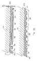
前記画像アイコンは基板内の凹みとして形成される画像アイコンを含み、前記凹みは基板とのコントラストを提供する材料で任意選択的に充填される間隙を形成する。
In a further exemplary embodiment, an image icon for use in a synthetic micro-optic system is disclosed, the synthetic magnification micro-optic system comprising:
(A) a micro image comprised of a substrate having a planar array of a plurality of image icons;
(B) a planar array of image icon focusing elements;
And the planar array of image icon collectors is disposed at a sufficient distance relative to the planar array of image icons such that the image collector is sufficient to form a composite image of the image icons;
The image icon includes an image icon formed as a depression in the substrate, the depression forming a gap that is optionally filled with a material that provides contrast with the substrate.
合成拡大マイクロ光学システムまたは文書セキュリティ装置、およびこれらを作成する方法もまた開示され、これらは、
(a)複数の画像アイコンの平面アレイから構成されるマイクロ画像と、
(b)画像アイコン集光素子の平面アレイであって、前記集光素子は多角形ベースマルチゾーンの集光素子を含む、画像アイコン集光素子の平面アレイと
を含む。
Synthetic magnification micro-optical systems or document security devices and methods of making them are also disclosed,
(A) a micro image composed of a planar array of a plurality of image icons;
(B) a planar array of image icon concentrating elements, wherein the condensing elements include a planar array of image icon condensing elements including polygon-based multi-zone condensing elements.
さらに、
(a)材料内に形成された充填された凹みからなるマイクロ画像またはアイコンの周期的アレイを有する材料と、
(b)集光素子がマイクロ画像またはアイコンの合成画像を形成するのに十分な距離に配置された、非円柱形、フラットフィールド、非球面、または多角形ベースマルチゾーンの微細(マイクロ)集光素子の周期的なアレイであって、前記微細集光素子は約20ミクロンから約30ミクロンの範囲のベース直径を有する集光素子を含み、
(c)マイクロ画像またはアイコンのアレイを覆う、着色または金属密封層、または覆い隠す層と、
を含む、セキュリティまたは認証スレッドが開示される。
further,
(A) a material having a periodic array of micro-images or icons consisting of filled depressions formed in the material;
(B) Non-cylindrical, flat field, aspherical, or polygon-based multi-zone fine (micro) condensing, where the concentrating elements are placed at a distance sufficient to form a micro image or a composite image of icons. A periodic array of elements, wherein the micro-concentrator comprises a concentrator having a base diameter in the range of about 20 microns to about 30 microns;
(C) a colored or metal sealing layer or covering layer that covers the array of microimages or icons;
A security or authentication thread is disclosed.
特に貨幣に用いられる文書セキュリティ装置またはセキュリティスレッドが開示され、これは、
(a)自身の平面内に対称軸を有する複数の画像アイコンの周期的な、回転対称な平面アレイから構成されるマイクロ画像と、
(b)マイクロ画像アレイの回転対称性と周期性に実質的に対応する回転対称性と周期性とを有し、自身の平面内に対称軸を有する、複数の画像アイコン集光素子の周期的な平面アレイであって、前記画像アイコン集光素子のアレイの対称軸は前記マイクロ画像平面アレイの対応する対称軸に対して選択された角度を有し、前記画像アイコン集光素子は、50ミクロン未満の有効直径を有するか、または多角形ベースマルチゾーン集光素子である集光素子を含み、前記画像アイコン集光素子の平面は前記画像アイコンの平面に実質的に平行に、画像集光素子が画像アイコンの合成画像を形成するのに十分な距離に配置される、画像アイコン集光素子の周期的平面アレイと、
を含む。
A document security device or security thread specifically used for money is disclosed,
(A) a micro-image composed of a periodic, rotationally symmetric planar array of a plurality of image icons having a symmetry axis in their own plane;
(B) periodicity of a plurality of image icon focusing elements having rotational symmetry and periodicity substantially corresponding to rotational symmetry and periodicity of the micro-image array, and having an axis of symmetry in its own plane; An array of image icon concentrators, the symmetry axis of the array of image icon concentrators having a selected angle with respect to the corresponding axis of symmetry of the micro image planar array; An image condensing element comprising a condensing element having an effective diameter of less than or being a polygon-based multi-zone condensing element, wherein the plane of the image icon condensing element is substantially parallel to the plane of the image icon A periodic planar array of image icon concentrators disposed at a distance sufficient to form a composite image of the image icons;
including.
また、画像および複数の画像集光素子を含む、合成拡大光学およびセキュリティシステムが開示され、前記集光素子および画像は互いに対して一平面に配置され、前記システムがシステムの平面に実質的に平行な軸回りに傾けられると、合成画像が傾斜された軸に平行な方向に動くように見える。 Also disclosed is a synthetic magnification optical and security system that includes an image and a plurality of image concentrating elements, wherein the concentrating elements and the image are arranged in a plane relative to each other, the system being substantially parallel to the plane of the system. When tilted around an arbitrary axis, the composite image appears to move in a direction parallel to the tilted axis.
本開示は、さらに、
(a)一つまたはそれ以上の光学スペーサと、
(b)その平面軸の少なくとも一つの回りに対称軸を有する複数の画像アイコンの周期的平面的なアレイから構成され、前記光学スペーサの上にまたは隣に配置されるマイクロ画像と、
(c)その平面軸の少なくとも一つの回りに対称軸を有する画像アイコン集光素子の周期的平面的なアレイであって、前記対称軸が前記マイクロ画像平面アレイの平面軸と同じ平面軸であり、各集光素子が、多角形のベースマルチゾーン集光素子、関連する画像アイコンの周辺端部が視界から抜け落ちないように関連画像の幅以上の拡大された視野を提供するレンズ、あるいは50ミクロン未満の有効直径を有する非球面集光素子、のいずれかである、
合成倍率マイクロ光学システム及びこれを製造する方法を提供する。
The present disclosure further includes:
(A) one or more optical spacers;
(B) a micro-image composed of a periodic planar array of a plurality of image icons having an axis of symmetry about at least one of its plane axes and disposed on or next to said optical spacer;
(C) a periodic planar array of image icon focusing elements having a symmetry axis about at least one of its planar axes, wherein the symmetry axis is the same planar axis as the planar axis of the micro image planar array Each condensing element is a polygonal base multi-zone condensing element, a lens that provides an enlarged field of view beyond the width of the associated image so that the peripheral edge of the associated image icon does not fall out of view, or 50 microns Any of aspherical concentrating elements having an effective diameter of less than
A synthetic magnification micro-optical system and a method of manufacturing the same are provided.
システムは前述された効果の内の一つまたは複数を含むことができる。前記効果をシステム内に選択的に含むことができる方法が提供される。 The system can include one or more of the effects described above. A method is provided in which the effects can be selectively included in the system.
本開示は、前述されたような少なくとも一つのマイクロ光学システムを備える、さらにセキュリティ文書、ラベル、開封テープ、タンパー表示装置、封印装置、または他の認証またはセキュリティ装置において、またはそれらに少なくとも部分的に取り込まれて、及びそれらに対してまたは関連して使用されるために適したセキュリティデバイス(手段)を提供する。さらに本開示は特に、
(a)一つまたはそれ以上の光学スペーサと、
(b)その平面軸の内の少なくとも一つの回りに対称軸を有し、光学スペーサ上またはその隣に配置される複数の画像アイコンの周期的平面的なアレイから構成されるマイクロ画像と、
(c)その平面軸の少なくとも一つの回りに対称軸を有する画像アイコン集光素子の周期的平面的なアレイであって、前記対称軸が前記マイクロ画像平面アレイの平面軸と同じ平面軸であり、各集光素子が多角形のベースマルチゾーン集光素子、関連する画像アイコンの周辺端部が視界から抜け落ちないように関連画像アイコンの幅を超える拡大された領域を提供するレンズ、または50ミクロン未満の有効直径を有する非球面集光素子のいずれかである、画像アイコン集光素子の周期的平面アレイと、
を備える、文書セキュリティデバイス(手段)及びこれを製造する方法を提供する。
The present disclosure further comprises, or at least partially, in a security document, label, opening tape, tamper display device, sealing device, or other authentication or security device, comprising at least one micro-optical system as described above. Provide a security device (means) suitable for being captured and used against or in connection with them. In addition, the present disclosure specifically
(A) one or more optical spacers;
(B) a micro-image comprising a periodic planar array of a plurality of image icons having an axis of symmetry about at least one of the plane axes and disposed on or adjacent to the optical spacer;
(C) a periodic planar array of image icon focusing elements having a symmetry axis about at least one of its planar axes, wherein the symmetry axis is the same planar axis as the planar axis of the micro image planar array , Each condensing element is a polygonal base multi-zone condensing element, a lens that provides an enlarged area beyond the width of the associated image icon so that the peripheral edge of the associated image icon does not fall out of view, or 50 microns A periodic planar array of image icon collectors, any of aspherical collectors having an effective diameter of less than
A document security device (means) and a method of manufacturing the same.
さらに、本開示は、衣料品、スキンケア製品、文書、印刷物、加工品、包装、店頭ディスプレイのポイント、出版物、広告手段、スポーツ製品、金融書類、及びトランザクションカード、及び他のすべての品物の視覚的な強化のための、少なくとも一つの、上記された構成の上記の効果を有するマイクロ光学システムを備える視覚強化装置を提供する。 In addition, this disclosure covers the visuals of clothing, skin care products, documents, printed materials, processed goods, packaging, point-of-sale displays, publications, advertising means, sports products, financial documents, and transaction cards, and all other items. A visual enhancement device comprising at least one micro-optical system having the above-described effects of the above-described configuration for effective enhancement.
前述されたような少なくとも1つのセキュリティ手段が少なくともその中に部分的に埋め込まれて、及び/またはその上に取り付けられて有するセキュリティ文書またはラベルも提供される。 Also provided is a security document or label having at least one security measure as previously described at least partially embedded therein and / or mounted thereon.
本開示のその他の特徴及び優位点は、以下の詳細な説明及び添付図面から当業者に明らかになるであろう。 Other features and advantages of the present disclosure will become apparent to those skilled in the art from the following detailed description and the accompanying drawings.
その他のシステム、デバイス(手段)、方法、特徴及び優位点は、以下の図面及び詳細な説明を検討することにより当業者に明らかになる、または明らかであろう。このような追加のシステム、方法、特徴及び優位点はすべて、本説明の範囲内に含まれ、本開示の適用範囲内に含まれ、添付請求項によって保護されることが意図されている。 Other systems, devices (means), methods, features and advantages will or will be apparent to those skilled in the art upon review of the following drawings and detailed description. All such additional systems, methods, features and advantages are included within the scope of this description, are intended to be included within the scope of this disclosure, and are protected by the accompanying claims.
別途定義されない限り、ここで使用されるすべての技術的な用語及び科学的な用語は、本発明が属する技術の当業者によって一般的に理解されるものと同じ意味を有する。ここで言及されるすべての出版物、特許出願、特許及び他の参考資料はその全体を参照することにより本書に組み込まれている。一致しない場合には、定義を含む本明細書の記載が優先される。さらに、本材料、方法及び例は例示に過ぎず、限定することを目的としていない。 Unless defined otherwise, all technical and scientific terms used herein have the same meaning as commonly understood by one of ordinary skill in the art to which this invention belongs. All publications, patent applications, patents and other references mentioned herein are hereby incorporated by reference in their entirety. In case of conflict, the present specification, including definitions, will prevail. In addition, the materials, methods, and examples are illustrative only and not intended to be limiting.
本開示の多くの態様は、図面を参照することによりさらによく理解できる。図中の構成要素は必ずしも縮尺どおりではなく、代わりに本開示の原則を明確に図解することに重きが置かれている。さらに、図中、類似する参照番号は複数の図全体で対応するパーツを指す。 Many aspects of the disclosure can be better understood with reference to the drawings. The components in the figures are not necessarily to scale, emphasis instead being placed upon clearly illustrating the principles of the present disclosure. Moreover, in the figures, like reference numerals designate corresponding parts throughout the several views.
ここで図に描かれている実施形態の説明を詳細に参照する。複数の実施形態はこれらの図に関連して説明されているが、本発明をここに開示されている一つまたは複数の実施形態に限定する意図はない。むしろ、すべての代替策、変型、及び同等物を対象とすることを意図している。 Reference will now be made in detail to the description of the embodiments depicted in the figures. Although embodiments are described in connection with these figures, there is no intent to limit the invention to one or more embodiments disclosed herein. Rather, it is intended to cover all alternatives, variations, and equivalents.
簡略にするため、また説明の繰り返しを避けるため、これ以降、以下の用語の全てに対する参照は、本明細書に定義され、説明され、詳述された通りに理解されるものである。便宜上、定義された用語は、以降、具体的な実施形態の説明において最初の使用例の際に太字で印刷される。 For the sake of brevity and avoidance of repeated explanations, references to all of the following terms are to be understood as defined, explained, and detailed herein. For convenience, the defined terms will be printed in bold during the first use case in the description of the specific embodiment.
アイコン充填材料−微細構造アイコン要素を充填するのに用いられるあらゆる材料。アイコン充填材料は、気体、液体、ゲル、粉末、固体、エマルジョン、懸濁、合成材料、およびこれらの組み合わせであってよい。アイコン充填材料は通常、周囲のアイコン層材料とある程度もしくは検出可能に異なるいくつかの特性を提供する。これらの異なる特性は、光学的効果を提供しうるか、もしくはこれらは、材料の非接触検出または認証、或いはこの両方を可能にする特性を提供しうる。アイコン充填材料には、多数の所望のアイコン要素特性を提供するために、材料の組み合わせを用いることができる。 Icon filling material-any material used to fill the microstructured icon element. The icon filling material may be a gas, liquid, gel, powder, solid, emulsion, suspension, synthetic material, and combinations thereof. Icon fill materials typically provide some properties that are somewhat or detectably different from the surrounding icon layer material. These different properties can provide optical effects, or they can provide properties that allow non-contact detection and / or authentication of the material. The icon fill material can use a combination of materials to provide a number of desired icon element properties.
望ましい光学的効果を作り出しうるアイコン充填材料の材料特性は、透明性、不透明性、屈折率、色分散、散乱特性、真珠光沢、オパール色、虹色、色反射および色吸収、反射性、線形、円形、楕円形の偏光特性、ラマン特性またはレーリー特性、旋光性、蛍光性、発光性、燐光性、2光子効果、熱発色性、圧電発色性、光発色性、トリボルミネッセンス性、エレクトロルミネッセンス性、エレクトロクロミック性(electrochromicity)、マグネトクロミック性(magnetochromicity)を含むが、これらに限定されない。アイコン充填材料は、これらの特性を、純材料として、または混合物、化合物、懸濁物、もしくはその他の多数の材料の組み合わせとして得ることができる。 The material properties of icon filling materials that can create the desired optical effect are: transparency, opacity, refractive index, chromatic dispersion, scattering properties, pearl luster, opal, iridescent, color reflection and color absorption, reflectivity, linear, Circular, elliptical polarization characteristics, Raman characteristics or Rayleigh characteristics, optical rotation, fluorescence, luminescence, phosphorescence, two-photon effect, thermochromic, piezoelectric coloring, photochromic, triboluminescence, electroluminescence, Including, but not limited to electrochromicity and magnetochromicity. Icon filling materials can obtain these properties as pure materials or as mixtures, compounds, suspensions, or combinations of many other materials.
所望の非接触検出もしくは認証特性を作り出すアイコン充填材料の材料特性は、磁気反応性、磁化、電荷分離、電気反応性、導電性、熱伝導性、誘電強度、蛍光性、発光性、燐光性、2光子効果、核磁気共鳴、透明性、不透明性、屈折率、色分散、散乱特性、真珠光沢、オパール色、虹色、色反射および色吸収、反射性、線形、円形、楕円形の偏光特性、ラマン特性もしくはレーリー特性、放射性、放射化性、旋光性、蛍光性、発光性、燐光性、2光子効果、熱発色性、圧電発色性、光発色性、トリボルミネッセンス性、エレクトロルミネッセンス性、エレクトロクロミック性、マグネトクロミック性を含むが、これらに限定されない。 The material properties of icon filling materials that create the desired non-contact detection or authentication properties are magnetic reactivity, magnetization, charge separation, electrical reactivity, conductivity, thermal conductivity, dielectric strength, fluorescence, luminescence, phosphorescence, Two-photon effect, nuclear magnetic resonance, transparency, opacity, refractive index, chromatic dispersion, scattering characteristics, pearl luster, opal color, iridescent, color reflection and color absorption, reflectivity, linear, circular, elliptical polarization characteristics , Raman characteristics or Rayleigh characteristics, radioactivity, activation, optical rotation, fluorescence, luminescence, phosphorescence, two-photon effect, thermochromic, piezoelectric color, photochromic, triboluminescence, electroluminescence, electro Including, but not limited to, chromic properties and magnetochromic properties.
アイコン充填材料は好ましくは、溶剤硬化、熱硬化、酸化硬化、反応硬化、または放射線硬化する、モノマー、オリゴマー、またはポリマー材料およびこれらの組み合わせなどのキャリヤ材料を含むことができる。例示的な放射線硬化されたフォトポリマーは、ロードインダストリーズ(Lord Industries)のU107フォトポリマーである。 The icon filling material may preferably include a carrier material such as a monomer, oligomer, or polymer material and combinations thereof that are solvent cured, heat cured, oxidatively cured, reactively cured, or radiation cured. An exemplary radiation cured photopolymer is Lord Industries U107 photopolymer.
アイコン充填キャリヤ材料の光学的、非接触検出および非接触認証特性は、これを、例えば以下のうちの、しかしこれらの材料には限定されないいずれかと混合、もしくは組み合わせることによって変更されることができる:染料、着色剤、顔料、粉末材料、インク、粉末鉱物、磁気材料および粒子、磁化材料および粒子、磁気反応材料および粒子、蛍光体、液晶、液晶ポリマー、カーボンブラックまたはその他の光吸収材料、二酸化チタン又はその他の光散乱材料、フォトニック結晶、非線形結晶、ナノ粒子、ナノチューブ、バッキーボール(buckyball)、バッキーチューブ(buckytube)、有機材料、真珠光沢材料、粉末真珠、多層干渉材料、オパール色材料、虹色材料、低屈折率材料又は粉末、高屈折率材料又は粉末、ダイヤモンド粉末、構造色材料、偏光材料、偏光回転材料、蛍光性材料、燐光性材料、熱発色性材料、圧電発色性材料、光発色性材料、トリボルミネッセンス材料、エレクトロルミネッセンス材料、エレクトロクロミック材料、マグネトクロミック材料および粒子、放射性材料、放射能活性化材料、エレクトレット電荷分離材料、これらの組み合わせ。例示的なアイコン充填材料は、サブミクロンの顔料粉末と共に砕かれて、厚い「インク」を形成するロードインダストリーズ(Lord Industries)のU107などのフォトポリマーキャリヤを含む。 The optical, non-contact detection and non-contact authentication properties of the icon-filled carrier material can be altered by mixing or combining it with, for example, any of the following, but not limited to these materials: Dyes, colorants, pigments, powder materials, inks, powder minerals, magnetic materials and particles, magnetized materials and particles, magnetic reaction materials and particles, phosphors, liquid crystals, liquid crystal polymers, carbon black or other light absorbing materials, titanium dioxide Or other light scattering materials, photonic crystals, nonlinear crystals, nanoparticles, nanotubes, buckyballs, buckytubes, organic materials, pearlescent materials, powdered pearls, multilayer interference materials, opal color materials, rainbows Color material, low refractive index material or powder, high refractive index material or powder, diamond powder, structure Color materials, polarizing materials, polarization rotating materials, fluorescent materials, phosphorescent materials, thermochromic materials, piezoelectric color developing materials, photochromic materials, triboluminescent materials, electroluminescent materials, electrochromic materials, magnetochromic materials and particles , Radioactive materials, radioactivity activated materials, electret charge separation materials, combinations thereof. An exemplary icon fill material includes a photopolymer carrier such as Lord Industries U107 that is crushed with submicron pigment powder to form a thick “ink”.
本明細書に明示的には教示されない他の特性、材料、方法、手段およびこれらの組み合わせは、当業者にとって明白であるように、本発明の範囲に含まれるものと理解される。 Other features, materials, methods, means and combinations thereof not explicitly taught herein are understood to be within the scope of the present invention, as will be apparent to those skilled in the art.
コーティング材料−アイコン層またはアイコン充填材料をコーティングするため、又は、レンズ、アイコン平面、アイコン層、微細構造アイコン要素、アイコン充填材料含むがこれに限定されないモアレ拡大システムの任意の層、もしくはレンズ、アイコン層、またはレンズ、アイコン層、基板、もしくは透明基板の内部または外部の任意の層に蒸着、積層、付着された、任意の材料の層をコーティングするために用いられる、任意の材料。 Coating material-any layer of a moire magnification system, or lens, icon for coating an icon layer or icon filling material, or including, but not limited to, lens, icon plane, icon layer, microstructured icon element, icon filling material Any material used to coat a layer, or any layer of material deposited, laminated, attached to any layer inside or outside a lens, icon layer, substrate, or transparent substrate.
コーティング材料は典型的に、アイコン層、アイコン充填材料、基板、透明基板もしくはレンズ層の他の材料の特性とは検出可能に異なるいくつかの特性を提供する。これらの異なる特性は、光学的効果を提供しうるか、もしくは材料の非接触検出又は認証、もしくはその両方を可能にする特性を提供しうる。材料をコーティングして多数の望ましいコーティング材料特性を提供するのに、材料の組み合わせを用いることができる。 The coating material typically provides several properties that are detectably different from the properties of the icon layer, icon fill material, substrate, transparent substrate, or other material of the lens layer. These different properties may provide an optical effect or may provide properties that allow non-contact detection and / or authentication of the material. Combinations of materials can be used to coat the materials to provide a number of desirable coating material properties.
所望の光学的効果を発生しうるコーティング材料の材料特性は、透明性、不透明性、屈折率、色分散、散乱特性、真珠光沢、オパール色、虹色、色反射および色吸収、反射性、線形、円形、楕円形の偏光特性、ラマン特性もしくはレーリー特性、旋光性、蛍光性、発光性、燐光性、2光子効果、熱発色性、圧電発色性、光発色性、トリボルミネッセンス、エレクトロルミネッセンス、エレクトロクロミック性、およびマグネトクロミック性を含むが、これらに限定されない。コーティング材料は、これらの特性を、純材料として、または混合、化合物、懸濁物、もしくはその他の多数の材料の組み合わせとして得ることができる。 The material properties of coating materials that can produce the desired optical effects are: transparency, opacity, refractive index, chromatic dispersion, scattering properties, pearl luster, opal color, iridescent, color reflection and color absorption, reflectivity, linear Circular, elliptical polarization characteristics, Raman characteristics or Rayleigh characteristics, optical rotation, fluorescence, luminescence, phosphorescence, two-photon effect, thermal coloring, piezoelectric coloring, photochromic, triboluminescence, electroluminescence, electro Including, but not limited to, chromic properties and magnetochromic properties. The coating material can obtain these properties as a pure material or as a mixture, compound, suspension, or combination of many other materials.
コーティング材料を塗布する適切な方法は、材料特性および材料の所望の機能もしくは効果を含む、多数の要因に依存する。金属、金属酸化物、半導体コーティング、およびこれらの組み合わせは、湿式還元反応(例えば湿式銀めっき)、無電解めっき、電気めっき、蒸着、スパッタリング、プラズマスプレー、分子線エピタキシー、ホットスタンプ、箔転写、積層、およびその他の適切かつ周知の手段、およびこれらの組み合わせによって塗布されることができる。液体キャリヤ材料を含むコーティング材料は、湿式コーティング、スプレー、印刷、積層、アイコン表面における化学反応、インクジェット、電子印刷、浸漬、メニスカスコーティング、ウェーブコーティング、反応コーティング、およびその他の適切かつ周知の手段、およびこれらの組み合わせによって塗布されることができる。フィルムもしくは箔ベースのコーティング材料は、ホットスタンプ、箔転写、積層、およびその他の適切かつ周知の手段、およびこれらの組み合わせによって塗布されることができる。 The appropriate method of applying the coating material depends on a number of factors, including material properties and the desired function or effect of the material. Metals, metal oxides, semiconductor coatings, and combinations of these include wet reduction reactions (eg wet silver plating), electroless plating, electroplating, vapor deposition, sputtering, plasma spray, molecular beam epitaxy, hot stamping, foil transfer, lamination , And other suitable and well-known means, and combinations thereof. Coating materials including liquid carrier materials include wet coating, spraying, printing, laminating, chemical reaction on the icon surface, ink jet, electronic printing, dipping, meniscus coating, wave coating, reactive coating, and other suitable and well known means, and It can apply | coat by these combination. Film or foil-based coating materials can be applied by hot stamping, foil transfer, lamination, and other suitable and well-known means, and combinations thereof.
コーティング材料は、好ましくは、蒸着またはスパッタリングされた、アルミニウム、金または銀などの金属、またはインジウムスズ酸化物もしくは酸化鉄などの金属酸化物であってよい。充填材料を含むコーティング材料は、好ましくは、溶剤硬化、熱硬化、酸化硬化、反応硬化、または放射線硬化された、モノマー、オリゴマー、またはポリマー材料およびこれらの組み合わせなどのキャリヤ材料を含んでよい。例示的な放射線硬化フォトポリマーは、ロードインダストリーズ(Lord Industries)のU107フォトポリマーである。 The coating material may preferably be a deposited or sputtered metal such as aluminum, gold or silver, or a metal oxide such as indium tin oxide or iron oxide. The coating material, including the filler material, may preferably include a carrier material such as a monomer, oligomer, or polymer material and combinations thereof that are solvent cured, thermally cured, oxidatively cured, reactively cured, or radiation cured. An exemplary radiation curable photopolymer is Lord Industries U107 photopolymer.
コーティングキャリヤ材料の、光学的な、非接触検出および非接触認証特性は、これを、例えば以下のうちの任意(しかしこれらの材料には限定されない)と混合し、もしくは組み合わせることにより、変更することができる:染料、着色剤、顔料、粉末材料、インク、粉末鉱物、磁気材料および粒子、磁化材料および粒子、磁気反応材料および粒子、蛍光体、液晶、液晶ポリマー、カーボンブラックまたはその他の光吸収材料、二酸化チタンまたはその他の光散乱材料、フォトニック結晶、非線形結晶、ナノ粒子、ナノチューブ、バッキーボール、バッキーチューブ、有機材料、真珠光沢材料、粉末パール、多層干渉材料、オパール色材料、虹色材料、低屈折率材料または粉末、高屈折率材料または粉末、ダイヤモンド粉末、構造色材料、偏光材料、偏光回転材料、蛍光性材料、燐光性材料、熱発色性材料、圧電発色性材料、光発色性材料、トリボルミネッセンス材料、エレクトロルミネッセンス材料、エレクトロクロミック材料、マグネトクロミック材料および粒子、放射性材料、放射能活性化材料、エレクトレット電荷分離材料、これらの組み合わせ。例示的なコーティング材料は、サブミクロン顔料粉末と共に砕かれて厚い「インク」を形成するロードインダストリーズ(Lord Industries)のU107などのフォトポリマーキャリヤを含む。 The optical, contactless detection and contactless authentication properties of the coating carrier material can be altered, for example, by mixing or combining it with any of the following (but not limited to these materials): Can: dyes, colorants, pigments, powder materials, inks, powder minerals, magnetic materials and particles, magnetized materials and particles, magnetic reaction materials and particles, phosphors, liquid crystals, liquid crystal polymers, carbon black or other light absorbing materials , Titanium dioxide or other light scattering materials, photonic crystals, nonlinear crystals, nanoparticles, nanotubes, buckyballs, bucky tubes, organic materials, pearlescent materials, powdered pearls, multilayer interference materials, opal color materials, iridescent materials, Low refractive index material or powder, high refractive index material or powder, diamond powder, structural color material, Optical material, polarization rotation material, fluorescent material, phosphorescent material, thermochromic material, piezoelectric colorant material, photochromic material, triboluminescent material, electroluminescent material, electrochromic material, magnetochromic material and particle, radioactive material , Radioactivity activated materials, electret charge separation materials, combinations of these. Exemplary coating materials include a photopolymer carrier, such as Lord Industries U107, which is crushed with submicron pigment powder to form a thick “ink”.
コーティング材料はまた、物理的、化学的、機械的、下塗り、もしくは付着促進特性を提供するために選択され得る。 The coating material can also be selected to provide physical, chemical, mechanical, primer, or adhesion promoting properties.
本明細書に明示的に教示されない他の特性、材料、方法、手段およびこれらの組み合わせは、当業者にとって明白であるように、本発明の範囲に含まれるものと理解される。 It is understood that other features, materials, methods, means and combinations thereof not explicitly taught herein are within the scope of the present invention, as will be apparent to those skilled in the art.
ポジティブアイコン要素−キャラクター(文字)やロゴなどのアイコン要素のオブジェクトパターンが着色され、色付けられ、金属化され、またはその他の方法でアイコン要素の背景から識別される、アイコンデザインもしくはパターンのグラフィカル要素。通常、製造のプロセスにおいて、ポジティブアイコン要素のオブジェクトパターンは、ポジティブアイコン要素の背景に得られるか又は適用されるあらゆる識別特性より前に、その識別特性を得る。 Positive icon element—A graphical element of an icon design or pattern in which the object pattern of an icon element, such as a character or logo, is colored, colored, metalized, or otherwise identified from the background of the icon element. Typically, in the manufacturing process, the object pattern of a positive icon element gets its identification characteristic before any identification characteristic obtained or applied to the background of the positive icon element.
ポジティブ画像−ポジティブアイコン要素によって形成される画像もしくは合成画像。 Positive image—an image or composite image formed by positive icon elements.
ネガティブアイコン要素−アイコン要素の背景が着色され、色付けられ、金属化され、またはその他の方法で、キャラクター(文字)やロゴなどのアイコン要素のオブジェクトパターンから識別される、アイコンデザインもしくはパターンのグラフィカル要素。通常、製造のプロセスにおいて、ネガティブアイコン要素の背景は、ネガティブアイコン要素のオブジェクトパターンに得られるか又は適用されるあらゆる識別特性の前に、その識別特性を得る。 Negative icon element-an icon design or pattern graphical element whose background is colored, colored, metalized, or otherwise identified from the object pattern of the icon element, such as a character or logo . Typically, in the manufacturing process, the background of a negative icon element gets its identification characteristic before any identification characteristic that is obtained or applied to the object pattern of the negative icon element.
ネガティブ画像−ネガティブアイコン要素によって形成された画像もしくは合成画像。 Negative image—an image or composite image formed by negative icon elements.
アイコン要素のオブジェクトパターン−キャラクター(文字)やロゴなどのアイコンデザインもしくはパターンの、分離および境界されたグラフィカル要素。通常、アイコン要素のオブジェクトパターンは、好ましくは、1、2、もしくは3のアイコン要素またはパターン内で境界されるが、より多くで境界されてもよい。 Icon element object pattern-a separate and bounded graphical element of an icon design or pattern, such as a character or logo. Typically, the icon element object pattern is preferably bounded within one, two, or three icon elements or patterns, but may be bounded more.
アイコン要素の背景−オブジェクトパターンを囲む、アイコンデザインもしくはパターンの境界されない領域。通常、アイコン要素またはパターンの背景は、複数のアイコン要素またはパターンにわたって連続している。 Icon element background-An unbounded area of an icon design or pattern that surrounds an object pattern. Typically, the icon element or pattern background is continuous across a plurality of icon elements or patterns.
アイコン層−基板もしくは透明基板の面に付着されるか、又は独立した層であってよい、実質的に平面的な微細印刷の層。アイコン層については、熱硬化ポリマー、熱形成ポリマー、キャストポリマー、反応キャストポリマー、放射線硬化ポリマー、生体ポリマー、ゼラチン、スターチ(でんぷん)、糖類、シリコンポリマー、多層誘電ポリマーフィルム、溶剤キャストポリマー、圧縮成形ポリマー、射出成形ポリマー、エンボスポリマー、ガラス、金属酸化物、ダイヤモンド、酸化アルミニウム、フォトポリマー、フォトレジスト、印刷インクもしくはパターン化されたコーティング、インクジェット印刷コーティング、電子印刷コーティング、およびこれらの組み合わせを含むがこれらに限定されない、多様な材料が用いられることができる。 Icon layer—A substantially planar microprinted layer that may be attached to the surface of a substrate or transparent substrate or may be a separate layer. For icon layers, thermosetting polymers, thermoforming polymers, cast polymers, reactive cast polymers, radiation curable polymers, biopolymers, gelatin, starch (starch), sugars, silicon polymers, multilayer dielectric polymer films, solvent cast polymers, compression molding Including polymers, injection molded polymers, embossed polymers, glass, metal oxides, diamonds, aluminum oxide, photopolymers, photoresists, printing inks or patterned coatings, inkjet print coatings, electronic print coatings, and combinations thereof A variety of materials can be used without being limited thereto.
例示的なアイコン層材料は、ロードインダストリーズ(Lord Industries)のU107フォトポリマーなどのフォトポリマーである。アイコン層は、単一の材料であることができ、或いは、染料、着色剤、顔料、粉末材料、インク、粉末鉱物、磁気材料および粒子、磁化材料および粒子、磁気反応材料および粒子、蛍光体、液晶、液晶ポリマー、カーボンブラックまたはその他の光吸収材料、二酸化チタンまたはその他の光散乱材料、フォトニック結晶、非線形結晶、ナノ粒子、ナノチューブ、バッキーボール、バッキーチューブ、有機材料、真珠光沢材料、粉末パール、多層干渉材料、オパール色材料、虹色材料、低屈折率材料もしくは粉末、高屈折率材料もしくは粉末、ダイヤモンド粉末、構造色材料、偏光材料、偏光回転材料、蛍光性材料、燐光性材料、熱発色性材料、圧電発色性材料、光発色性材料、トリボルミネッセンス材料、エレクトロルミネッセンス材料、エレクトロクロミック材料、マグネトクロミック材料および粒子、放射性材料、放射能活性材料、エレクトレット電荷分離材料、これらの組み合わせ、および、光学的、電気的、磁気的、核磁気共鳴またはその他の物理的特性を強化するか又は変更する、その他の適切な材料を含むことができる。 An exemplary icon layer material is a photopolymer, such as Lord Industries U107 photopolymer. The icon layer can be a single material, or it can be a dye, colorant, pigment, powder material, ink, powder mineral, magnetic material and particles, magnetized material and particles, magnetic reaction material and particles, phosphor, Liquid crystal, liquid crystal polymer, carbon black or other light absorbing material, titanium dioxide or other light scattering material, photonic crystal, nonlinear crystal, nanoparticle, nanotube, buckyball, bucky tube, organic material, nacreous material, powdered pearl , Multilayer interference material, opal color material, iridescent material, low refractive index material or powder, high refractive index material or powder, diamond powder, structural color material, polarizing material, polarization rotating material, fluorescent material, phosphorescent material, heat Chromogenic material, piezoelectric chromogenic material, photochromic material, triboluminescent material, electroluminescent material, energy Enhances chromochromic materials, magnetochromic materials and particles, radioactive materials, radioactive materials, electret charge separation materials, combinations thereof, and optical, electrical, magnetic, nuclear magnetic resonance or other physical properties Other suitable materials can be included or modified.
例示的なアイコン層材料は、ロードインダストリーズ(Lord Industries)のU107フォトポリマーである。本明細書に明示的に教示されない他の特性、材料、方法、手段およびこれらの組み合わせは、当業者にとって明白であるように、本発明の範囲に含まれるものと理解される。 An exemplary icon layer material is Lord Industries U107 photopolymer. It is understood that other features, materials, methods, means and combinations thereof not explicitly taught herein are within the scope of the present invention, as will be apparent to those skilled in the art.
微細構造アイコン画像要素−熱形成、鋳造(キャスティング)、圧縮成形、射出成形、エンボス、パターン化放射線照射(露光)および現像、レーザ露光および現像、インクジェット印刷、電子印刷、印刷、彫刻、電鋳、刻線(ruling)、写真、ホログラフィー、および周知の硬化、エッチングまたは膨潤プロセスと組み合わされた感光性エマルジョン(乳剤)のレーザ照射、マスキングおよび堆積過プロセス、マスキングおよび化学エッチング、マスキングおよび反応イオンエッチング、マスキングおよびイオンビームフライス、マイクロマシニング(加工)、レーザ加工およびレーザアブレーション(切除)、フォトポリマー露光および現像、およびその他の適切な手段およびこれらの組み合わせを含む、多くの適切な手段によってアイコン層内に形成されることができる、物理的起伏または微細構造を有するアイコン要素。 Microstructure icon image elements-thermoforming, casting (casting), compression molding, injection molding, embossing, patterned radiation exposure (exposure) and development, laser exposure and development, inkjet printing, electronic printing, printing, engraving, electroforming, Ruling, photography, holography, and laser irradiation of photosensitive emulsion (emulsion) combined with well-known curing, etching or swelling processes, masking and deposition over-process, masking and chemical etching, masking and reactive ion etching, Icons can be obtained by many suitable means, including masking and ion beam milling, micromachining, laser machining and laser ablation, photopolymer exposure and development, and other suitable means and combinations thereof. May be formed in the layer, icon elements having physical relief or microstructure.
微細構造画像要素は、好ましくは、液体フォトポリマーを、ポリマー基板(通常はPET)とニッケルの微細構造アイコン画像要素ツールとの間でキャスティングし、上記のフォトポリマーを放射線硬化し、上記のポリマー基板を、それに付着した硬化フォトポリマーと共に上記のニッケル微細構造アイコン画像要素ツールから剥がすことによって形成される。 The microstructure image element preferably casts a liquid photopolymer between a polymer substrate (usually PET) and a nickel microstructure icon image element tool, radiation curing the photopolymer, and the polymer substrate. Is peeled from the nickel microstructure icon image element tool described above with the cured photopolymer attached thereto.
本明細書に明示的に教示されないその他の特性、材料、方法、手段、およびこれらの組み合わせは、当業者にとって明らかであるように、本発明の範囲に含まれるものと理解される。 Other features, materials, methods, means, and combinations thereof not explicitly taught herein are understood to be within the scope of the present invention, as will be apparent to those skilled in the art.
微細構造アイコン画像要素ツールおよび方法−熱形成、鋳造(キャスティング)、圧縮成形、射出成形、エンボス、パターン化放射線照射および現像、電鋳法、フォトポリマー照射(露光)および現像により、微細構造アイコン画像要素をアイコン層内に形成するのに用いられるツール(工具)および方法。上記のツールは、熱形成、鋳造、圧縮成形、射出成形、エンボス、パターン化放射線照射および現像、レーザ照射(露光)および現像、インクジェット印刷、電子印刷、印刷、彫刻、電鋳、刻線、写真、ホログラフィー、周知の硬化およびエッチングまたは膨潤プロセスと組み合わされた感光性エマルジョン(乳剤)のレーザ照射、マスキングおよび堆積プロセス、マスキングおよび化学エッチング、マスキングおよび反応性イオンエッチング、マスキングおよびイオンビームフライス、マイクロマシニング、レーザ加工およびレーザアブレーション(切除)、フォトポリマー照射(露光)および現像、およびその他の適切な手段およびこれらの組み合わせを含む、多くの類似する適切な手段によって作成されることができる。 Microstructure Icon Image Elements Tools and Methods-Microstructural icon images by thermoforming, casting (casting), compression molding, injection molding, embossing, patterned radiation irradiation and development, electroforming, photopolymer irradiation (exposure) and development Tools and methods used to form elements in the icon layer. The above tools are thermoforming, casting, compression molding, injection molding, embossing, patterned radiation irradiation and development, laser irradiation (exposure) and development, ink jet printing, electronic printing, printing, engraving, electroforming, engraving, photography Holography, laser irradiation of photosensitive emulsion (emulsion) combined with well-known curing and etching or swelling processes, masking and deposition processes, masking and chemical etching, masking and reactive ion etching, masking and ion beam milling, micromachining , Laser processing and laser ablation (ablation), photopolymer irradiation (exposure) and development, and other suitable means and combinations thereof, can be made by many similar suitable means.
微細構造アイコン画像要素ツールは、好ましくは、硬質基板もしくは硬質透明基板上でのフォトレジスト材料の光露光および現像、微細構造フォトレジスト表面の導電金属化、および導電面上へのニッケル電鋳により、オリジナルの微細構造を生成する周知の方法によって作られる。 The microstructure icon image element tool preferably comprises photoexposure and development of a photoresist material on a rigid substrate or rigid transparent substrate, conductive metallization of the microstructured photoresist surface, and nickel electroforming on the conductive surface. It is made by a well-known method of generating the original microstructure.
本明細書に明示的に教示されていないその他の特性、材料、方法、手段、およびこれらの組み合わせは、当業者にとって明らかであるように、本発明の範囲に含まれるものと理解される。 Other features, materials, methods, means, and combinations thereof not explicitly taught herein will be understood to be within the scope of the present invention, as will be apparent to those skilled in the art.
透明基板−ユニゾンモアレ拡大システムの光学素子(要素)を支持するのに用いられる、ガラス、金属酸化物、ポリマー、複合材料、生体ポリマー、糖類、セルロース、スターチ、ゼラチンおよびこれらの組み合わせを含むがこれらに限定されない、任意の実質的に平面的かつ実質的に光学的に透明な材料であって、上記の光学素子は、マイクロレンズアレイおよび1以上のアイコン画像アレイを任意選択的に含む。本発明のアイコン層およびモアレ拡大システムについての例示的な基板はPETポリマーフィルムである。 Transparent substrates—including glass, metal oxides, polymers, composites, biopolymers, sugars, cellulose, starch, gelatin and combinations thereof used to support the optical elements of the Unison moire magnification system Any substantially planar and substantially optically transparent material, including, but not limited to, the optical element optionally includes a microlens array and one or more icon image arrays. An exemplary substrate for the icon layer and moire magnification system of the present invention is a PET polymer film.
本明細書に明示的に教示されないその他の特性、材料、方法、手段、およびこれらの組み合わせは、当業者にとって明らかであるように、本発明の範囲に含まれるものと理解される。 Other features, materials, methods, means, and combinations thereof not explicitly taught herein are understood to be within the scope of the present invention, as will be apparent to those skilled in the art.
基板−ガラス、金属、複合材料、金属酸化物、ポリマー、生体ポリマー、糖類、セルロース、スターチ、ゼラチン、紙、繊維質材料、非繊維質材料、箔、不織紙代用品、およびこれらの組み合わせを含むがこれに限定されない、任意の実質的に平面的な材料。本発明のための例示的な基板はPETポリマーフィルムである。 Substrate-glass, metal, composite material, metal oxide, polymer, biopolymer, sugar, cellulose, starch, gelatin, paper, fibrous material, non-fibrous material, foil, non-woven paper substitute, and combinations thereof Any substantially planar material, including but not limited to. An exemplary substrate for the present invention is a PET polymer film.
本明細書に明示的に教示されないその他の特性、材料、方法、手段、およびこれらの組み合わせは、当業者にとって明らかであるように、本発明の範囲に含まれるものと理解される。 Other features, materials, methods, means, and combinations thereof not explicitly taught herein are understood to be within the scope of the present invention, as will be apparent to those skilled in the art.
共形(conformal)コーティング材料−塗布される表面の形状に一致するコーティング材料。スパッタされた金属コーティングは典型的な共形である。これは、水平面と同様に、垂直表面、微細構造側面およびアンダーカット領域をコーティングする。 Conformal coating material—a coating material that matches the shape of the surface to be applied. Sputtered metal coatings are typically conformal. This coats vertical surfaces, microstructured sides and undercut areas as well as horizontal planes.
非共形コーティング材料−塗布される表面の形状に一致しないコーティング材料。蒸着金属コーティング典型的な非共形である。これは、水平面を選択的にコーティングするが、垂直表面および微細構造側面のコーティングは不十分であり、アンダーカット領域はコーティングしない。 Non-conformal coating material—a coating material that does not match the shape of the applied surface. Vapor deposited metal coating is a typical non-conformal. This selectively coats the horizontal plane, but the vertical and microstructure side coatings are inadequate and the undercut areas are not coated.
指向性(directional)コーティング材料−水平面および、コーティングソース(源)の通常の方向を指す表面法線を有する表面を選択的にコーティングするが、コーティングソースの通常の方向から離れる方向を指す表面法線を有する表面をコーティングしない、コーティング材料。オフセットもしくはバッフル蒸着金属コーティングは、指向性コーティング材料の一例である。金属蒸気の流れは、表面において実質的に法線から外れた角度に向けられるために、微細構造の「近い」面はコーティングされるが、微細構造の「遠い」面は影となりコーティングされない。 Directional coating material—a surface normal that selectively coats a surface having a horizontal plane and a surface normal pointing to the normal direction of the coating source, but pointing away from the normal direction of the coating source. Coating material with no coating on the surface. An offset or baffle deposited metal coating is an example of a directional coating material. Because the metal vapor flow is directed at an angle that is substantially off-normal at the surface, the “near” surface of the microstructure is coated, while the “far” surface of the microstructure is shaded and uncoated.
ここで図面を参照すると、図1aは、システムの画像の視差直交移動を提供する本発明のマイクロ光学システム12の一実施形態を描いている。
Referring now to the drawings, FIG. 1a depicts one embodiment of a
システム12は、少なくとも二つの実質的に等しい対称軸を有し、二次元の周期的アレイに配列されているマイクロレンズ1。レンズ直径2は好ましくは50μ未満であり、レンズ3の間の間隙は好ましくは5μ以下である(同じ測定値を意味するために用語「μ」と「μm」を同義的に使用している)。マイクロレンズ1はアイコン要素4の画像に焦点を合わせ、この画像10を観察者に向かって投射する。システムは一般的には通常レベルの周囲照明を有する状況で使用されるため、アイコン画像の照明は反射された、または透過した周辺(環境)光から生じる。アイコン要素4はレンズ1を含むレンズアレイの周期と寸法とに実質的に類似する周期と寸法を有するアイコン要素の周期的アレイの一つの要素である。レンズ1とアイコン要素4の間には、レンズ1の材料と連続している、あるいはオプションとして(任意選択的に)別の基板8であってよい光学スペーサ5がある。(この実施形態ではレンズ9は基板から分離されている。)アイコン要素4は、好ましくは高分子材料製の密封層6によって任意選択的に保護されてよい。密封層6は、透明、半透明、薄い色が付いた、有色素、不透明、金属性、磁気、光学的に可変、または望ましい光学効果及び/またはセキュリティと認証のための追加の機能性を提供する、これらの任意の組み合わせであってよく、追加の機能性には、光学効果、導電率、または静電容量、磁場検出に依存する自動的貨幣認証、検証、追跡調査、計数及び検出のシステムのサポートが含まれる。
The
システムの総厚さ7は通常50μ未満である。実際の厚さはレンズ1のF#(F値)とレンズの直径2、及び追加のセキュリティ機能層または光学効果層の厚さに依存する。アイコン要素4の反復周期11はレンズ1の反復周期に実質的に同一である。「縮尺比率(scale ratio)」、つまりレンズの反復周期に対するアイコンの反復周期の比率が、多くの異なる光学効果を生じさせるために使用される。実質的に1.0000に等しい軸に沿って対称的な縮尺比率の値は、レンズとアイコンの対称軸がずれているときにはユニゾンモーション視差直交効果を生じさせ、1.0000未満の軸対称的な縮尺比率の値は、レンズとアイコンの対称軸が実質的に位置合わせされているときにはユニゾンディープ効果とユニゾンスーパーディープ効果を生じさせ、1.0000より大きい軸対称的な縮尺比率の値は、レンズとアイコンの対称軸が実質的に位置合わせされているときにはユニゾンフロート効果とユニゾンスーパーフロート効果を生じさせる。X方向に0.995及びY方向に1.005等の、軸非対称的な縮尺比率の値はユニゾン浮揚効果を生じさせる。
The
ユニゾンモーフ効果は、レンズ反復周期とアイコン反復周期のどちらかまたは両方の縮尺の歪み(ねじれ)によって、あるいはアイコンパターンの中に空間的に変化する情報を組み込むことによって得られる。ユニゾン3−D効果も、アイコンパターンの中に空間的に変化する情報を組み込むことによって生成されるが、本実施形態では情報はアイコンの位置に実質的に一致する特定の位置から見られるような三次元オブジェクトのさまざまな視点を表す。 The unison morph effect is obtained by distortion (twisting) of either the lens repetition period and / or the icon repetition period, or by incorporating spatially varying information in the icon pattern. The unison 3-D effect is also generated by incorporating spatially varying information in the icon pattern, but in this embodiment the information is seen from a specific position that substantially matches the icon position. Represents various viewpoints of 3D objects.
図1bは、反復周期11のレンズ1とアイコン4の正方形のアレイパターン及び光学スペーサ厚さ5を有する、図1aの断面に描かれているように本システムの等角図を提示する(図1aは正方形のアレイパターンに特有ではなく、すべての規則正しい周期的アレイパターンの代表的な断面である)。アイコン要素4は、前部の一部を切り取った断面で明確に見られる「$」画像として示されている。レンズ1とアイコン要素4の間には実質的に1対1の対応があるが、レンズアレイの対称軸は、一般的にアイコンアレイの対称軸と厳密には整列していない。
FIG. 1b presents an isometric view of the system as depicted in the cross-section of FIG. 1a, having a square array pattern of
縮尺比率が1.0000の、図1aから図1bのユニゾン(視差直交運動)材料の実施形態の場合、レンズ1の軸とアイコン要素4の軸が実質的に一列であるときには、アイコン要素の結果として生じる合成画像(この例では、巨大な「$」)は「膨張(blow-up)」し、理論上無限に近づく係数(factor)により拡大される。レンズ1の軸とアイコン要素4の軸のわずかな角度の非整列により、アイコン要素の合成画像の拡大比率が減少し、拡大された合成画像を回転される。
For the unison (parallax orthogonal motion) material embodiment of FIGS. 1 a to 1 b with a scale ratio of 1.0000, the result of the icon element when the axis of the
レンズ、光学スペーサ、アイコンの特定の組み合わせにより作成されたモーション合成画像は、視角の所与の変更に対して一貫した量だけ動き、この一貫した量は、合成画像の反復距離の割合である。例えば、0.25インチの反復距離を有する合成画像を提供するユニゾンモーション材料が作成され、視角が10度変わる時にこれらの合成画像が0.1インチの視差直交運動を有するように見える場合、1.0インチの合成画像反復距離を有するユニゾンを作成するのに用いられる同じレンズ、アイコン、およびスペーサは、視角が10度変わる時に、比例して大きな0.4インチの視差直交運動を示すことになる。視差直交画像運動の量は、作成された合成画像の反復距離に適合するようにスケーリングされる。視角の変化とスケーリングされた視差直交運動との間の関係は、用いられるレンズのF#に依存する。F#の低いレンズは、選択された視角の変化に対して、F#の大きなレンズよりも少ない量の視差直交運動を生じさせる。 A motion composite image created by a particular combination of lens, optical spacer, and icon moves a consistent amount for a given change in viewing angle, which is a percentage of the composite image's repeat distance. For example, if unison motion materials are created that provide composite images with a repeat distance of 0.25 inches and these composite images appear to have a 0.1 inch parallax orthogonal motion when the viewing angle changes by 10 degrees, 1 The same lens, icon, and spacer used to create a unison with a composite image repeat distance of .0 inches will show a proportionally large 0.4 inch parallax motion when the viewing angle changes by 10 degrees. Become. The amount of parallax orthogonal image motion is scaled to fit the repetition distance of the created composite image. The relationship between viewing angle change and scaled parallax orthogonal motion depends on the F # of the lens used. A lens with a low F # causes a lesser amount of parallax motion for a selected change in viewing angle than a lens with a large F #.
ユニゾンモーション材料のために用いられる例示的なレンズは、0.8のF#を有してよい。これが所望のF#であることの理由の1つは、これが観察者の左目によって見られる画像と右目によって見られる画像との間の垂直視差を最小化するからである。垂直視差は、左目で見た画像と右目で見た画像との間の垂直方向のずれである。一方の画像は他方の画像に対して、垂直方向にずれているように見える。水平方向の画像視差は、普通で自然な現象である。これは、三次元の奥行きを認識するのに目−脳システムによって用いられる因子の1つである。人は通常、垂直方向の画像視差に遭遇しない。これは双眼鏡または双眼顕微鏡で、光学部品がずれている場合に時々見られることができる。水平方向の画像視差は、両眼の視界を有する人間に連続的に発生するが、垂直方向の画像視差は、自然界では決して起こらないので、人はこの垂直方向の画像視差に適応することにごく限られた能力しか有さない。このような適応には、一方の目が他方の目に対してわずかに上向きもしくは下向きであることが要求される。これは不自然な経験であり、人に悪影響を与えることがないが、不慣れな眼筋動作の結果として、すぐに観察者の目に身体的な感覚をもたらす。この身体的な感覚は、「眼が変な感じである」から「見づらい」まで多様な方法で説明されてきた。この影響は、視野の方位角方向に関係なく存在する(すなわち、ユニゾンモーション材料は、その効果を失うことなくその平面内の任意の角度に回転されることができる)。いかなる種類の従来の印刷も、観察者の眼にこの身体的感覚を引き起こすことはない。 An exemplary lens used for unison motion material may have an F # of 0.8. One reason that this is the desired F # is because it minimizes the vertical parallax between the image seen by the viewer's left eye and the image seen by the right eye. Vertical parallax is a vertical shift between an image viewed with the left eye and an image viewed with the right eye. One image appears to be offset in the vertical direction relative to the other image. Horizontal image parallax is a normal and natural phenomenon. This is one of the factors used by the eye-brain system to recognize 3D depth. People usually do not encounter vertical image parallax. This can sometimes be seen with binoculars or binocular microscopes when the optical components are misaligned. Horizontal image parallax occurs continuously in humans with binocular vision, but vertical image parallax never occurs in nature, so humans are very adaptable to this vertical image parallax. Has limited ability. Such adaptation requires that one eye is slightly upward or downward relative to the other eye. This is an unnatural experience and does not adversely affect humans, but immediately results in a physical sensation in the viewer's eyes as a result of unfamiliar eye muscle movement. This physical sensation has been described in a variety of ways, ranging from “the eye feels strange” to “difficult to see”. This effect exists regardless of the azimuthal direction of the field of view (ie, unison motion material can be rotated to any angle in its plane without losing its effect). Any kind of conventional printing does not cause this physical sensation in the observer's eyes.
ユニゾンモーション材料は、画像の垂直方向視差を強化することで、観察者にこの感覚を引き出すよう設計されることができる。観察者の眼は水平面に配置されているため、ユニゾンモーション材料には垂直方向の画像視差が存在する。左目からの視野は、右目からの視野とは異なる水平角度からであるので、左目によって見られる合成画像は、右目によって見られる合成画像に対して垂直方向に視差直交的に移動され、したがって垂直方向の画像視差を生じる。垂直方向画像視差の量は、低いF#のレンズでは小さく、通常は観察者に気づかれない。しかし、観察者の眼に垂直方向の視差感覚を意図的に作成するために、F#が2.0以上などのより大きなF#のレンズを用いることにより垂直方向の画像視差を強化することができる。 Unison motion materials can be designed to bring this sensation to the viewer by enhancing the vertical parallax of the image. Since the observer's eyes are arranged in a horizontal plane, there is vertical image parallax in the unison motion material. Since the field of view from the left eye is from a different horizontal angle than the field of view from the right eye, the composite image seen by the left eye is shifted in a parallax perpendicular to the composite image seen by the right eye, and thus vertical Produces image parallax. The amount of vertical image parallax is small for low F # lenses and is usually not noticed by the observer. However, in order to intentionally create a vertical parallax sensation in the viewer's eyes, vertical image parallax can be enhanced by using a larger F # lens such as F # 2.0 or higher. it can.
ユニゾンモーション材料において強化された垂直方向の画像視差を作成することにより得ることのできる1つの利点は、このように観察者に引き出される身体的感覚が固有、即時、かつ自動的なものであり、したがって新規の認証方法として機能できることである。他の既知の材料のどれも、視野の全ての方位角方向から類似の感覚を提供することはできない。 One advantage that can be gained by creating an enhanced vertical image parallax in unison motion material is that the physical sensation thus elicited by the viewer is unique, immediate and automatic, Therefore, it can function as a new authentication method. None of the other known materials can provide a similar sensation from all azimuthal directions of the field of view.
ユニゾンディープ、ユニゾンフロート、ユニゾン浮揚の実施形態の合成拡大比率は、システムの縮尺比率だけではなく、レンズ1の軸とアイコン要素4の軸の角度的整列にも依存する。縮尺比率が1.0000に等しくないとき、これらの軸が実質的に整列していることから得られる最大倍率は1/(1.0000−(縮尺比率))の絶対値に等しい。したがって、0.995の縮尺比率を有するユニゾンディープ材料は|1/(1.000−0.995)|=200xという最大倍率を示すであろう。同様に、1.005の縮尺比率を有するユニゾンフロート材料も|1/(1.000−1.005)|=200xという最大倍率を示すであろう。ユニゾンモーション材料の実施形態に類似した方法で、ユニゾンディープ、ユニゾンフロート、及びユニゾン浮揚の実施形態のレンズ1の軸とアイコン要素4の軸のわずかな角度の非整列はアイコン要素の合成画像の拡大比率を減少させ、拡大された合成画像を回転させる。
The combined magnification ratio of the Unison Deep, Unison Float, and Unison Levitation embodiments depends not only on the scale ratio of the system, but also on the angular alignment of the
ユニゾンフロートまたはスーパーフロートのアイコンパターンにより生じる合成画像は逆様であり、ユニゾンフロートまたはスーパーフロートのアイコンパターンの向きに関して百八十度(180°)回転しているが、ユニゾンディープまたはスーパーディープのアイコンパターンにより生じる合成画像は、ユニゾンディープまたはスーパーディープのアイコンパターンの向きに関して垂直である。 The composite image produced by the Unison Float or Super Float icon pattern is reversed and is rotated 180 degrees (180 °) with respect to the orientation of the Unison Float or Super Float icon pattern, but the Unison Deep or Super Deep icon The composite image produced by the pattern is perpendicular with respect to the orientation of the unison deep or super deep icon pattern.
図2aは、ユニゾンモーション実施形態で見られる直感に反した視差直交画像運動効果を概略的に描いている。図2aの左側は、水平軸16を中心に振動18する、一個のユニゾンモーション材料12を平面図で描いている。合成拡大された画像14がパ視差に従って移動すると、それは、材料12が水平軸16の回りで振動するのにつれて(図2aに示されているように)上下に変位するように見えるであろう。このような明白な視差運動は実際のオブジェクト、従来のプリント及びホログラフィック画像に特有であろう。合成倍率画像14は、視差運動を示す代わりに視差直交運動20(通常予想される視差運動方向に垂直である運動)を示す。図2aの右側は、それが水平回転軸16を中心に振動する18に従った単一の合成倍率画像14の視差直交運動を示す一個の材料12の斜視図を描いている。点線の輪郭22は、合成倍率画像14が視差直交によって右に移動した後の位置を示し、点線の輪郭24は、合成倍率画像14が視差直交によって左に移動した後の位置を示している。
FIG. 2a schematically depicts the intuitional parallax orthogonal image motion effect seen in the Unison Motion embodiment. The left side of FIG. 2a depicts a single
ユニゾンディープとユニゾンフロートの実施形態の視覚的な効果が、図2b、図2cに等角的に描かれている。図2bは、一個のユニゾンディープ材料26が、観察者30の目で見られるときに立体視ではユニゾンディープ材料26の平面の下にあるように見える合成倍率画像28を提示する。図2cは、一個のユニゾンフロート材料32が、観察者30の目で見られるときに立体視ではユニゾンフロート材料34の平面の上にあるように見える合成倍率画像34を提示する。ユニゾンディープ効果とユニゾンフロート効果は全方位視点位置で、及び垂直仰角(ユニゾンディープ材料26またはユニゾンフロート材料32への観察者30の目の視線方向が材料の表面の垂直であるような)から通常45度未満である浅い仰角まで広範囲の仰角位置で可視である。幅広い範囲の視角と向きでのフロート効果は、ユニゾンディープ材料とユニゾンフロート材料を、円柱形のレンズ状の光学部品またはホログラフィーを使用するシミュレーションから区別する、単純且つ簡単な方法を提供する。
The visual effects of the Unison Deep and Unison Float embodiments are depicted isometrically in FIGS. 2b and 2c. FIG. 2 b presents a composite magnification image 28 in which a single unison deep material 26 appears to be below the plane of the unison deep material 26 in stereoscopic view when viewed with the eye of an
ユニゾン浮揚実施形態効果が、図2dから図2fに、ユニゾン浮揚材料36の三つの異なる方位角回転における合成倍率画像38の立体視で知覚される奥行き位置を示す等角図、及びこれらに対応する、観察者30の目によって見られるユニゾン浮揚材料36及び合成倍率画像38の平面図によって描かれている。図2dは、前記材料が平面図で図示されるように傾けられているときに立体視的にユニゾン浮揚材料36の下の平面にあるように見える画像として合成倍率画像38(以下「画像」と称する)を描いている。平面図の中の濃い太線は説明のための方位角向きの基準37として示されている。図2dでは、向きの基準37が垂直方向に整列し、画像38が水平方向に整列していることに注意されたい。縮尺比率が、観察者の二つの目の瞳孔を結ぶ線と実質的に平行に位置合わせ(整列)されたユニゾン浮揚材料36の第一の軸に沿って1.000未満であるため(これを以後「立体視縮尺比率」と呼ぶ)、画像38はユニゾンディープ位置に見える。ユニゾン浮揚材料36の立体視縮尺比率はこの第一の軸に垂直な第二の軸に沿って1.000を上回り、それにより第二の軸が図2fに示されているように観察者の目の瞳孔を結ぶ線に実質的に平行に位置合わせされるとき、画像38のユニゾンフロート効果を生じさせる。向きの基準37はこの図の水平位置にあることに注意されたい。図2eはこの方角的向きの立体視縮尺比率が実質的に1.000であるためにユニゾンモーション視差直交画像効果を生じさせるユニゾン浮揚材料36の中間の方角的向きを描く。
The unison levitation embodiment effect is equivalent to FIGS. 2d to 2f, and isometric views showing the perceived depth position in the stereoscopic view of the
材料が方角的に回転するにつれてユニゾン浮揚材料36の下(図2d)からユニゾン浮揚材料36の高さ(図2e)まで、及びさらにユニゾン浮揚材料36の上の高さ(図2f)まで移動するユニゾン浮揚画像38の視覚的な効果は、ユニゾン浮揚材料36を従来の印刷情報と結合することにより強化できる。従来の印刷物の変化しない立体視奥行きは、画像38の立体視奥行き移動をさらによく知覚するための基準平面として働く。
As the material rotates directionally, it moves from below the unison levitation material 36 (FIG. 2d) to the height of the unison levitation material 36 (FIG. 2e) and further to a height above the unison levitation material 36 (FIG. 2f). The visual effect of the
ユニゾン材料が「ポイント」光源(例えば、スポットライトまたはLEDフラッシュライト)または平行光源(例えば、太陽光)等の強力な指向性の光源によって照明されるとき、アイコンの「影の画像」が見られてよい。これらの影の画像は多くの点で特異である。ユニゾンにより提示される合成画像は、照明の方向が移動するにつれて移動しないが、生じる影の画像は移動する。さらに、ユニゾン合成画像は材料の平面とは異なる視覚面にありうる一方、影の画像はつねに材料の平面上にある。影の画像の色はアイコンの色である。したがって、黒いアイコンは黒い影の画像を生じさせ、緑のアイコンは緑の影の画像を生じさせ、白のアイコンは白の影の画像を生じさせる。 When the unison material is illuminated by a strong directional light source such as a “point” light source (eg spotlight or LED flashlight) or a parallel light source (eg sunlight), an icon “shadow image” is seen. It's okay. These shadow images are unique in many ways. The composite image presented by Unison does not move as the direction of illumination moves, but the resulting shadow image moves. Further, the unison composite image may be on a different visual plane than the material plane, while the shadow image is always on the material plane. The color of the shadow image is the color of the icon. Thus, a black icon produces a black shadow image, a green icon produces a green shadow image, and a white icon produces a white shadow image.
照明の角度が移動するにつれての影の画像の移動は、合成画像内に存在する視覚的な効果と同様に、特有の奥行きまたはモーションユニゾン効果に結び付けられる。したがって、光の角度が変化するにつれての影の画像の移動は、視角が変化されるときに合成画像が示す移動に匹敵する。特に、
モーションの影画像は、光源が移動するにつれて視差直交的に移動する。
ディープの影の画像は光源と同じ方向で移動する。
フロートの影の画像は光源の反対の方向に移動する。
浮揚の影の画像は前記の組み合わせである方向で移動する。
即ち、浮揚のディープ影画像は左右方向では光と同じ方向で移動するが、上下方向では光の方向と反対に移動する、又は浮揚フロート影画像は左右方向では光と反対に移動するが、上下方向では光と同じ方向で移動する、又は浮揚モーション影画像は光の移動に対して視差直交運動を示す。
The movement of the shadow image as the illumination angle moves is linked to a unique depth or motion unison effect, as well as the visual effects present in the composite image. Therefore, the movement of the shadow image as the angle of light changes is comparable to the movement that the composite image shows when the viewing angle is changed. In particular,
The motion shadow image moves in a parallax orthogonal manner as the light source moves.
Deep shadow images move in the same direction as the light source.
The float shadow image moves in the opposite direction of the light source.
The levitating shadow image moves in a direction that is a combination of the above.
That is, the levitated deep shadow image moves in the same direction as the light in the left-right direction, but moves in the up-down direction opposite to the light direction, or the levitating float shadow image moves in the left-right direction opposite to the light, The direction moves in the same direction as the light, or the levitation motion shadow image shows parallax orthogonal motion with respect to the movement of light.
ユニゾンモーフの影画像は、光源が移動するにつれてモーフィング効果を示す。 The unison morph shadow image shows a morphing effect as the light source moves.
追加的な特異な影の画像の効果は、LED光等の発散する点光源がユニゾンフィルムに向かって移動し、及びユニゾンフィルムから離れるときに見られる。光源がさらに遠いときには、その発散する光線はさらに平行光線に非常に近似し、ディープ、スーパーディープ、フロートまたはスーパーフロートユニゾン合成画像によって生じる影の画像は合成画像とほぼ同じ大きさに見える。光が表面により近くにされると、フロートとスーパーフロートの材料の影の画像は拡大するが、照明が強力に発散的であるためディープ材料とスーパーディープ材料の影の画像は縮小する。これらの材料を集束照明で照明すると、フロート影画像とスーパーフロート影画像は縮小するが、ディープ影画像とスーパーディープ影画像は合成画像より大きなサイズに拡大する。 Additional singular shadow image effects are seen when a diverging point source, such as LED light, moves toward and away from the Unison film. When the light source is farther away, its diverging rays are much closer to parallel rays, and the shadow image produced by the deep, super deep, float or super float unison composite image appears to be approximately the same size as the composite image. As the light is brought closer to the surface, the shadow image of the float and super float material will expand, but the shadow image of the deep and super deep material will shrink because the illumination is strongly divergent. When these materials are illuminated with focused illumination, the float shadow image and the super float shadow image are reduced, but the deep shadow image and the super deep shadow image are enlarged to a size larger than the synthesized image.
ユニゾンモーション材料の影画像は照明の集束または発散の変更につれて大幅に縮尺を変更せず、むしろ影の画像は照明の中心の回りを回転する。ユニゾン浮揚の影画像は、照明の集束または発散の変化されるときに一方向で縮小し、その垂直方向で拡大する。ユニゾンモーフの影の画像は、照明の集束または発散の変化につれて特定のモーフパターンに特有な様式で変化する。 The unison motion material shadow image does not scale significantly as the illumination focus or divergence changes, rather the shadow image rotates around the center of the illumination. The unison levitation shadow image shrinks in one direction when the illumination focus or divergence changes, and expands in that vertical direction. The unison morph shadow image changes in a manner specific to a particular morph pattern as the illumination focus or divergence changes.
これらの影画像の効果はすべてセキュリティ、偽造防止、ブランド保護用途、及び他の類似した用途のために活用されるユニゾン材料のための追加的な認証方法として使用できる。 All of these shadow image effects can be used as additional authentication methods for unison materials utilized for security, anti-counterfeiting, brand protection applications, and other similar applications.
図3aから図3iは、マイクロレンズの対称的な二次元アレイのさまざまなパターンの多様な実施形態と充填比(fill-factor)を示す平面図である。図3a、図3d及び図3gは、それぞれ正六角形のアレイパターン40で配列されるマイクロレンズ46、52及び60を描いている(破線のアレイパターン線40、42及び44はレンズのパターンの対称を示すが、必ずしもレンズアレイの物理的な要素を表現していない)。図3aのレンズはほぼ円形のベース形状46を有し、図3gのレンズはほぼ六角形のベース形状60を有し、図3dのレンズは角を丸くされた六角形52である中間的なベース形状を有する。レンズ形状の類似する発展がレンズ48、54及び62の正方形のアレイ42に適用され、これらのレンズは、図3b、図3e及び図3hで見られるようにほぼ円形48から角を丸くされた正方形54、ほぼ正方形62に及ぶベース形状を有する。対応して、正三角形アレイ44は、図3c、図3f及び図3iに見られるようにほぼ円形50から角を丸くされた三角形58、ほぼ三角形64に及ぶベース形状を有する。
Figures 3a to 3i are plan views showing various embodiments and fill-factors of various patterns of a symmetric two-dimensional array of microlenses. 3a, 3d, and 3g depict microlenses 46, 52, and 60, respectively, arranged in a regular hexagonal array pattern 40 (dashed array pattern lines 40, 42, and 44 show the symmetry of the lens pattern). But does not necessarily represent the physical elements of the lens array). The lens of FIG. 3a has a generally
図3aから図3iのレンズパターンは、本システムのために使用できるレンズを代表的に表している。レンズ間の間隙は画像の合成倍率に直接的に寄与しない。これらのレンズパターンの一つを使用して作成される材料も、同じ幾何学形状で、ほぼ同じ縮尺で配列されるアイコン要素のアレイを含み、ユニゾンモーション、ユニゾンディープ、ユニゾンフロート及びユニゾン浮揚の効果を生じさせるために使用される縮度の差異が許容される。図3cに示されているように間隙が大きい場合には、レンズは低い充填比を有するとされ、画像と背景間のコントラストはアイコン要素から散乱する光により減少する。間隙が狭い場合には、レンズは高充填比を有するとされ、画像と背景の間のコントラストが高くなり、レンズ自体に優れた焦点特性をもたらし、アイコン要素はレンズの焦点面の中に含まれる。一般的には、正方形または三角形のベースより、円形またはほぼ円形のベースの高品質の光マイクロレンズを形成する方が容易である。レンズ性能と間隙の最小化の優れたバランスは図3d、つまり角を丸くされた六角形のベース形状を有するレンズの六角形のアレイに示されている。 The lens patterns of FIGS. 3a-3i typically represent lenses that can be used for the present system. The gap between the lenses does not directly contribute to the image combining magnification. The material created using one of these lens patterns also includes an array of icon elements with the same geometry and arranged at approximately the same scale, and the effects of unison motion, unison deep, unison float and unison levitation Differences in the degree of shrinkage used to produce If the gap is large as shown in FIG. 3c, the lens is said to have a low fill ratio and the contrast between the image and the background is reduced by light scattered from the icon element. When the gap is narrow, the lens is said to have a high fill ratio, the contrast between the image and the background is high, the lens itself has excellent focus properties, and the icon element is contained within the focal plane of the lens . In general, it is easier to form a high quality optical microlens with a circular or nearly circular base than a square or triangular base. An excellent balance of lens performance and gap minimization is shown in FIG. 3d, a hexagonal array of lenses having a hexagonal base shape with rounded corners.
低いF#を有するレンズは、本システムでの使用に特に適している。ここで低F#は4未満を意味し、特にユニゾンモーションの場合、約2以下を意味する。低F#のレンズは、その直径に対して高い曲率及び対応して大きな凹形曲線(サグ:sag)、又は中心の厚さを有する。F#が0.8の典型的なユニゾンレンズは、幅28ミクロン、中心厚さ10.9ミクロンの六角形のベースを有する。直径が50ミクロン、焦点距離が200ミクロンの典型的なドリンクウォーター(Drinkwater)レンズは4というF#と、3.1ミクロンという中心厚さを有する。同じベースサイズに縮小すると、ユニゾンレンズはドリンクウォーターレンズのほぼ6倍の大きさの凹形曲線を有する。 A lens with a low F # is particularly suitable for use in the present system. Here, low F # means less than 4, especially in the case of unison motion, it means about 2 or less. A low F # lens has a high curvature and a correspondingly large concave curve (sag) or center thickness for its diameter. A typical unison lens with an F # of 0.8 has a hexagonal base with a width of 28 microns and a center thickness of 10.9 microns. A typical Drinkwater lens with a diameter of 50 microns and a focal length of 200 microns has an F # of 4 and a center thickness of 3.1 microns. When reduced to the same base size, the Unison lens has a concave curve that is almost six times as large as a drink water lens.
出願人は、例えば六角形のベースマルチゾーンレンズ等の多角形ベースのマルチゾーンレンズが円形ベースの球面レンズに優る重要且つ予期しない優位点を有することを発見した。前述されたように、六角形ベースマルチゾーンレンズはそのストレスを緩和する形状のために製造性を大幅に改善するが、六角形ベースのマルチゾーンレンズを使用することにより取得される追加的な予期されていない光学利点がある。 Applicants have discovered that polygon-based multi-zone lenses, such as hexagonal base multi-zone lenses, have important and unexpected advantages over circular-based spherical lenses. As mentioned earlier, hexagon-based multi-zone lenses significantly improve manufacturability due to their stress-relieving shape, but additional expectations obtained by using hexagon-based multi-zone lenses There are optical advantages that are not.
それぞれが本発明に異なった独自の優位点を提供する三つの光学ゾーンを所有するために、これらのレンズをマルチゾーンと呼ぶ。三つのゾーンは中心ゾーン(レンズの面積のほぼ半分を構成する)、側面ゾーン及び角ゾーンである。これらの多角形レンズは、中心ゾーンの回りの角ゾーンの内部に描画され、側面ゾーンを含む円の直径である有効直径を有する。 These lenses are referred to as multi-zones because each possesses three optical zones that provide different unique advantages to the present invention. The three zones are the central zone (which constitutes approximately half of the lens area), the side zone and the corner zone. These polygonal lenses are drawn inside the angular zone around the central zone and have an effective diameter that is the diameter of the circle containing the side zones.
本発明の六角形ベースのマルチゾーンレンズの中心ゾーンは、少なくとも同じ直径と焦点距離を有する球面と同様に、光を焦点させる非球面形状(例えば、公称焦点距離が28ミクロンの直径28ミクロンのレンズについて[y=(5.1316E)X4−(0.01679)X3+(0.124931)X+11.24824]によって定められる形状を有する)を有する。図30は高分子基板786(レンズと基板n=1.51)において公称焦点距離が28ミクロン、公称直径28ミクロンの六角形ベースマルチゾーンレンズ784の中心ゾーン780焦点特性782を示し、図31は高分子基板794(レンズと基板n=1.51)において公称焦点距離30ミクロン、直径28ミクロンの球面レンズ792の中心ゾーン788の焦点特性790を示している。これら二つの図の比較は、本開示の六角形マルチゾーンレンズ784も、少なくとも球面レンズ792と同様に機能することを明確に立証している。六角形ベースマルチゾーンレンズ784の中心ゾーン780は、高い画像解像度とさまざまな視角からの浅い被写界深度(shallow depth of field)を提供する。
The central zone of the hexagonal-based multi-zone lens of the present invention has an aspherical shape that focuses light (eg, a 28 micron diameter lens with a nominal focal length of 28 microns, as well as a spherical surface having at least the same diameter and focal length. [Y = (5.1316E) X4- (0.01679) X3 + (0.124931) X + 11.24824]). FIG. 30 shows a
本発明の六角形ベースマルチゾーンレンズ784の六つの側面ゾーン796のそれぞれは、ゾーンの位置に複雑に依存する焦点距離を有するが、その効果は側面ゾーン796の焦点を、図32に描かれているように中心ゾーン焦点の約+/−10パーセントに及ぶ値の範囲798で拡散させることである。焦点のこの垂直方向のぶれ798は、これらのゾーン796内のレンズの被写界深度を効果的に増加し、フラットフィールドレンズ(flat-field lens)を有するのと同等の利点を提供する。球面レンズ792の外側ゾーン800の性能は図33に示されている。焦点802の垂直方向のぶれは、六角形ベースマルチゾーンレンズ784の場合より球面レンズ792の場合は著しく少ない。
Each of the six
これはオフノーマル表示にとって特に重要である。つまり増加した被写界深度及び効果的な平坦な視野により、その曲線状の焦点面がアイコン平面から分離されるときに球面レンズで発生する可能性がある突然の画像ピンボケが軽減される。その結果、六角形ベースマルチゾーンレンズを使用するユニゾン材料は、球面レンズを使用する同等なユニゾン材料よりさらに高い視角でより穏やかに焦点からフェードする合成画像を表示する。これは、それにより材料の有効視角が増し、したがってセキュリティ装置または画像プレゼンテーション装置としての実用性が高まるために望ましい。 This is particularly important for off-normal displays. That is, the increased depth of field and effective flat field of view reduce sudden image blur that can occur with a spherical lens when its curved focal plane is separated from the icon plane. As a result, unison materials using hexagon-based multi-zone lenses display a composite image that fades more gently from focus at higher viewing angles than comparable unison materials using spherical lenses. This is desirable because it increases the effective viewing angle of the material, thus increasing its utility as a security device or image presentation device.
図32の六角形ベースマルチゾーンレンズ784の角ゾーン806は、発散焦点特性を持ち、周囲の照明をアイコン平面上に散乱808することにより、ユニゾン材料の感度を照明状態に合わせて減少させる予期されない利点を提供する。図33の球面レンズ792は、(アイコン平面領域804の中に散乱する光線がないことによって確かめられるように)広い領域で周囲照明を散乱せず、したがって球面レンズを使用して作られるユニゾン材料は、六角ベースマルチゾーンレンズを使用して作られるユニゾン材料より種々の角度から見られるときにより大きな合成画像輝度変化を有する。
The
例示的な六角形ベースマルチゾーンレンズから得られる利点は、六角形ベースマルチゾーンレンズが球面レンズより高い充填比(平面を覆う能力)を有するためにさらに拡大される。球面レンズ間の間隙は事実上周辺光の散乱をもたらさないが、この非散乱領域は六角形ベースマルチゾーンレンズの場合はるかに小さい。 The benefits gained from the exemplary hexagonal base multizone lens are further expanded because the hexagonal base multizone lens has a higher fill ratio (capability to cover the plane) than a spherical lens. The gap between the spherical lenses effectively does not cause ambient light scattering, but this non-scattering region is much smaller for hexagonal-based multi-zone lenses.
したがって、従来の光学規格によって評価されたとき六角形ベースマルチゾーンのレンズの焦点特性が球面レンズの焦点特性より劣っているとしても、本発明の状況においては、六角形ベースマルチゾーンレンズは球面レンズに優る予期されていない利点及び優位点を提供する。 Therefore, in the context of the present invention, a hexagonal base multi-zone lens is a spherical lens, even though the focal characteristic of a hexagonal base multizone lens is inferior to that of a spherical lens when evaluated by conventional optical standards. Provides unexpected benefits and advantages over.
いずれかのタイプのレンズは、アイコン平面上への周囲照明の散乱を強化するために、散乱微細構造またはレンズ間隙空間の中に導入される、あるいは組み込まれる散乱物質を追加することにより利益を得ることができる。さらにレンズ間隙空間は、周辺照明をアイコン平面上に導くために集束するまたは発散する焦点特性の小半径の凹凸(メニスカス)レンズを形成する材料で充填できる。これらの方法は例えば光散乱粒子をレンズ間隙凹凸レンズ充填材料の中に組み込むことによって結み合わされてよい。代替的に、レンズ間隙ゾーンは最初から適切な散乱レンズ間隙ゾーンを用いて製造されてもよい。 Either type of lens benefits by adding scattering material introduced or incorporated into the scattering microstructure or lens gap space to enhance the scattering of ambient illumination onto the icon plane be able to. Further, the lens gap space can be filled with a material that forms a small radius meniscus lens with a focusing characteristic that converges or diverges to guide ambient illumination onto the icon plane. These methods may be combined, for example, by incorporating light scattering particles into the lens gap relief lens filler material. Alternatively, the lens gap zone may be manufactured from the beginning with a suitable scattering lens gap zone.
フィルムの表面とレンズの端縁間の高い接触角度が、製造中に工具からレンズを分離するためにかけられる力の応力(ストレス)集中部として働くため、これらの比率を有する球面レンズは製造が非常に困難である。これらの高いストレスはレンズのフィルムへの付着を失敗させ、工具からのレンズの取り外しを失敗させる傾向がある。さらに、低F#の球面レンズの光学性能はレンズの中心から離れる半径方向のゾーンについて徐々に危うくなる。つまり低F#の球面レンズはそれらの中心ゾーン近く以外では十分に焦点が合わない。 Spherical lenses with these ratios are very producible because the high contact angle between the film surface and the lens edge acts as a stress concentrator for the force applied to separate the lens from the tool during manufacture. It is difficult to. These high stresses tend to cause the lens to fail to adhere to the film and fail to remove the lens from the tool. In addition, the optical performance of low F # spherical lenses is gradually compromised for radial zones away from the center of the lens. That is, low F # spherical lenses are not fully focused except near their central zone.
六角形ベースレンズは、さらにほぼ円形のベースを有するレンズに対して予期されていない重要な利点を有する。つまり、六角形のレンズは、ほぼ円形のベースの光学的に同等なレンズより低い剥離力で工具から取り外される。六角形のレンズは、その中心近くでほぼ軸対称な形状から、六角形に対称な形状に融合する形状を、ベースで応力集中部として働く角とともに有する。鋭いベース角により引き起こされる応力の集中により、レンズを製造中にそれらのモールドから分離するために必要とされる全体的な剥離力が削減される。この効果はかなりの大きさである。製造中の剥離力は、ほぼ円形のベースレンズに比較して、六角形ベースのレンズの場合2または3以上の係数で、削減できる。 Hexagonal base lenses also have significant unexpected benefits over lenses having a substantially circular base. That is, the hexagonal lens is removed from the tool with a lower peel force than the optically equivalent lens of the substantially circular base. The hexagonal lens has a shape that fuses from a substantially axially symmetric shape near its center to a symmetric shape with a hexagonal shape, with an angle that acts as a stress concentrating portion at the base. The stress concentration caused by the sharp base angle reduces the overall peel force required to separate the lenses from their molds during manufacture. This effect is significant. The peel force during manufacture can be reduced by a factor of 2 or more for hexagonal base lenses as compared to nearly circular base lenses.
材料の画像コントラストは、不透明な有色の光を吸収する(濃い色の)材料でレンズ間隙空間を充填することにより強化することができ、これは事実上、レンズのためのマスクを形成する。これによりレンズ間隙空間を通じてアイコン層から散乱する光から生じるコントラストの減少が低減される。この間隙充填による追加的な効果は、入射する周囲照明が間隙を通ってアイコン平面に通過するのが遮られるために画像全体がより暗くなるという点である。その周辺に迷走集束を有するレンズにより生じる画像の明瞭性も、この充填剤が迷走周辺レンズゾーンを閉塞する不透明な有色素性の間隙充填剤により改善できる。 The image contrast of the material can be enhanced by filling the lens gap space with a material that absorbs opaque colored light (dark color), which in effect forms a mask for the lens. This reduces the reduction in contrast resulting from light scattered from the icon layer through the lens gap space. An additional effect of this gap filling is that the entire image becomes darker because incident ambient illumination is blocked from passing through the gap to the icon plane. The clarity of the image produced by a lens with stray focus around it can also be improved by the opaque pigmented gap filler that closes the stray peripheral lens zone.
別の効果は間隙空間を白または明るい色の材料、あるいはユニゾン材料に使用される基板に色が一致する材料で充填することにより得られる。明るい色のレンズ間隙充填が十分に濃密であり、アイコン平面がアイコン要素と背景の間で強力なコントラストを有している場合、ユニゾン合成画像は、反射光で見られるときには実質的に非可視であり、レンズ側から透過光で見られるときにははっきりと可視であるが、アイコン側から見られるときには不可視となる。これにより透過光でのみ可視で、一方の側からだけ可視である一方向透過画像を有するという新規なセキュリティ効果が提供される。 Another effect is obtained by filling the interstitial space with a white or light colored material, or a material that matches the color of the substrate used for the unison material. If the bright color lens gap fill is sufficiently dense and the icon plane has a strong contrast between the icon element and the background, the unison composite image will be substantially invisible when viewed in reflected light. Yes, it is clearly visible when viewed from the lens side with transmitted light, but is invisible when viewed from the icon side. This provides a novel security effect of having a unidirectional transmission image that is visible only through transmitted light and visible only from one side.
蛍光材料は、追加的な認証手段を提供するために、可視光顔料の代わりに、あるいは可視光顔料に加えて、レンズ間隙コーティングに使用できる。 Fluorescent materials can be used in lens gap coatings in place of or in addition to visible light pigments to provide additional means of authentication.
図4は、本材料の軸に沿った立体視縮尺比率、SSR(アイコン要素反復周期/レンズアレイ反復周期)を変更したときの効果を図示する。1.0000より大きいSSRを有するシステムのゾーンはユニゾンフロート効果とスーパーフロート効果を生じさせ、実質的に1.0000を有するゾーンはユニゾンモーション視差直交運動(OOPM)効果を生じさせ、1.0000未満のSSRを有するゾーンはユニゾンディープ効果とユニゾンスーパーディープ効果を生じさせる。システムフィルムの軸に沿って変動させることにより、これらの効果のすべてを生じさせ、種々の方法で一方から別の方へ遷移させることができる。この図は、無限の種々のこのような組み合わせの一つを描いている。破線66は、実質的に1.0000に一致するSSR値、ユニゾンディープとユニゾンスーパーディープ、及びユニゾンフロートとユニゾンスーパーフロートの間の分界線、及びOPMを示すSSR値を示している。ゾーン68では、ユニゾン材料のSSRは0.995であり、ユニゾンディープ効果を生じさせる。
FIG. 4 illustrates the effect of changing the stereoscopic scale ratio, SSR (icon element repetition period / lens array repetition period) along the axis of the material. Zones of systems with SSRs greater than 1.000 produce unison float and super float effects, while zones with substantially 1.000 produce unison motion parallax orthogonal motion (OOPM) effects, less than 1.0000 Zones with SSRs of 5 cause unison deep effects and unison super deep effects. By varying along the axis of the system film, all of these effects can be produced and transitioned from one to the other in various ways. This figure depicts one of an infinite variety of such combinations. Dashed
これに隣接しているのは、SSRが0.995から最大1.005まで傾斜し、ユニゾンディープからユニゾンフロート効果への空間的な遷移を生じさせるゾーン70である。次のゾーン72のSSRは1.005であり、ユニゾンフロート効果を生じさせる。次のゾーン74はユニゾンフロート効果からユニゾンディープ効果への下方への円滑な遷移を生じさせる。ゾーン76はユニゾンディープ効果から上方に段階的にOPMに、ユニゾンフロート効果に進み、ゾーン78でOPMに段階的に戻る。これらの効果を達成するために必要とされる反復周期の変化は、通常、アイコン要素層の中で最も容易に実現される。合成倍率画像を実質的に類似したサイズに保つために、各ゾーンの中でSSRを変化させることに加え、アレイの各ゾーンの回転角度を、好ましくはアイコン要素アレイの範囲内で変えることが望ましい。
Adjacent to this is
このグラフを解釈する最も簡単な方法は、それを一個の本システム材料のこの軸全体で知覚されるだろう立体視奥行きの断面として見ることである。したがって、立体的に彫刻された画像の視野、つまり輪郭が付けられた視覚的な表面を、SSRの局所的な制御により、及びオプションとして対応するアレイ回転角度の局所的な制御により作成することができる。この立体的に彫刻された表面は、人間の顔を含む無制限の範囲の形状を表すために使用できる。立体的に彫刻されたグリッド、つまり周期的ドットの効果を生じさせるアイコン要素のパターンは、複雑な表面を視覚的に表示するための特に効果的な方法でありうる。 The simplest way to interpret this graph is to view it as a cross-section of stereoscopic depth that would be perceived across this axis of a single system material. Thus, a field of view of a three-dimensionally sculpted image, ie a contoured visual surface, can be created by local control of the SSR and optionally by local control of the corresponding array rotation angle. it can. This three-dimensionally sculpted surface can be used to represent an unlimited range of shapes including the human face. A three-dimensionally sculpted grid, i.e. a pattern of icon elements that creates the effect of periodic dots, can be a particularly effective way to visually display complex surfaces.
図5aから図5cは、本システムの材料の製造において一方のアレイパターンを他方に関して回転させる効果を描く平面図である。図5aは、アレイ軸の角度の大きな変化がない規則正しい周期的なアレイ間隔82を有するレンズアレイ80を示す。図5bは、アレイ軸方位角度86が漸次的に変化するアイコン要素アレイ84を示す。レンズアレイ80が、図示されているように、レンズアレイをアイコンアレイの上に平行移動させることによりアイコン要素アレイ84と結み合わされる場合、結果として生じる近似する視覚効果が図5cに示されている。図5cでは、レンズアレイ80とアイコンアレイ84を結合することにより作成された材料88が、材料全体で縮尺と回転が変化する合成倍率画像89,90、91のパターンを作成する。画像89は材料88の上端に向かって大きく、回転は小さい。画像90は、材料88の中上部に向かって小さくなり、画像89に対してかなりの角度で回転される。画像89と91の間のさまざまな縮尺と回転はレンズパターン82とアイコン要素パターン86の角度のある非整列(位置ずれ)における差異の結果である。
Figures 5a to 5c are plan views depicting the effect of rotating one array pattern with respect to the other in the manufacture of the material of the system. FIG. 5a shows a
図6aから図6cは、一つの合成倍率OPM画像98を別の合成倍率画像102に、第一の画像がアイコン要素パターン92と94内で境界104を横切って移動するにつれて、モーフィングさせるための方法を描く。アイコン要素パターン92は、拡大された差込図96に示される円形のアイコン要素98を持っている。アイコン要素パターン94は、拡大された差込図100に示されている星形のアイコン要素102を持っている。アイコン要素パターン92と94は別々のオブジェクトではないが、その境界104で接合されている。材料がアイコン要素のこの結合パターンを使用して組み立てられるとき、結果として生じるOPM画像は図6bと図6cに描かれているモーフィング効果を示すであろう。図6bは、境界104を横切って右107に移動し、右に移動するにつれ星画像102が境界から出現するOPM円形画像98を示している。画像106は、遷移中であり、それが境界を越えるときの部分円及び部分星である。図の図6cは、画像がさらに右に移動した後の画像を示している。つまり画像98が今度は境界104にさらに近づいており、画像106は円から星へのその変型を完了するために境界をほとんど完全に越えている。モーフィング効果は、確かな(hard)境界104を有する代わりに一方のアイコン要素パターンから他方への遷移ゾーンを作成することにより、より突然ではなく達成できる。遷移ゾーンでは、アイコンは一連の段階を通して徐々に円から星に変化するであろう。結果として生じるOPM画像の視覚的なモーフィングの円滑さは遷移に使用される段階の数に依存するだろう。画像的な可能性の範囲は無限である。例えば、遷移ゾーンは、円が収縮する一方、鋭い星の一点がそこから突出してくるように見えるように、あるいは代わりに円の側面が内向きに窪んでずんぐりした星を生成し、それが最終的なデザインに到達するまで漸次鋭くなっていくように設計できる。
FIGS. 6a to 6c illustrate a method for morphing one composite
図7aから図7cは、アイコン要素の代替的実施形態を描く本システムの断面である。図7aは光学スペーサ5によってアイコン要素108から分離されるレンズ1を有する材料である。アイコン要素108は光学スペーサ5の下面に塗布される無色、有着、薄い色の付いた、あるいは染料のパターンにより形成されている。この種のアイコン要素108を付着させるためには、印刷解像度が十分に細かい限り、インクジェット、レーザジェット、凸版印刷、フレキソ印刷、グラビア印刷、及び凹版印刷等の多数の一般的な印刷方法のいずれもが使用できる。
Figures 7a to 7c are cross sections of the present system depicting alternative embodiments of icon elements. FIG. 7 a is a material having a
図7bは、アイコン要素112の別の実施形態を用いた類似した材料システムを描いている。この実施形態では、アイコン要素は支持材料110に埋め込まれている顔料、染料、または粒子から形成される。この実施形態の支持材料110内のアイコン要素112の例は、写真乳剤としてのゼラチンの中の銀粒子、インクレセプタまたはコーティングに吸収された有色素性のまたは染色されたインク、染料レセプタコーティングの中への染料昇華転写、及び画像形成フィルムの光発色(フォトクロミック)性画像または熱発色(サーモクロミック)性画像を含む。 FIG. 7 b depicts a similar material system using another embodiment of the icon element 112. In this embodiment, the icon elements are formed from pigments, dyes, or particles that are embedded in the support material 110. Examples of icon elements 112 in the support material 110 of this embodiment include silver particles in gelatin as a photographic emulsion, pigmented or dyed ink absorbed in an ink receptor or coating, in a dye receptor coating. Dye sublimation transfer to a photochromic image and a photochromic or thermochromic image of an image forming film.
図7cは、アイコン要素114を形成する微細構造手法を描いている。この方法には、ほとんど無制限の空間解像度という利点がある。アイコン要素114は、微細構造113または立体(ソリッド)領域115の中の間隙から、単独であるいは組み合わせで形成できる。間隙(void)113は任意選択的に蒸着金属、異なる屈折率を有する材料、あるいは染料または有色素材料等の別の材料で充填またはコーティングできる。 FIG. 7 c depicts a microstructure technique for forming the icon element 114. This method has the advantage of almost unlimited spatial resolution. The icon elements 114 can be formed alone or in combination from the gaps in the fine structure 113 or the three-dimensional (solid) region 115. The void 113 can optionally be filled or coated with a vapor deposited metal, a material with a different refractive index, or another material such as a dye or pigmented material.
図8a、図8bは、アイコン要素のポジティブな実施形態とネガティブな実施形態を描く。図8aは、透明な背景118を背にして着色された、染められた、あるいは有色素性120のポジティブなアイコン要素116を示している。図8bは、着色された、染められたあるいは有色素性の背景120を背にして透明118であるネガティブなアイコン要素122を示している。本システムの材料はポジティブとネガティブの両方のアイコン要素をオプションとして組み込んでよい。ポジティブなアイコン要素とネガティブなアイコン要素を作成するこの方法は、図7cの微細構造アイコン要素に特によく適応される。
Figures 8a and 8b depict positive and negative embodiments of icon elements. FIG. 8 a shows a positive icon element 116 colored, dyed or pigmented 120 against a
図9は、本システムのピクセルゾーン材料の一実施形態の断面図を示す。本実施形態は、短い焦点を有するレンズ124のあるゾーンと、長い焦点136を有するレンズのある他のゾーンを含む。短焦点レンズ124は、レンズ124の焦点面に配置されているアイコン平面128内のアイコン要素129の画像123を投射する。長焦点レンズ136は、レンズ136の焦点面に配置されているアイコン平面132内のアイコン要素137の画像134を投射する。光学分離体126は、端焦点レンズ124をその関連付けられるアイコン平面128から分離する。長焦点レンズ136は、光学分離体126、アイコン平面128、及び第二の光学分離体130の厚さの合計分、その関連アイコン平面132から分離される。第二のアイコン平面132内のアイコン要素137は短焦点レンズ124の焦点深度外であるため、短焦点レンズゾーンで明確な合成倍率画像を形成しない。同様に、アイコン要素129は長焦点レンズ136に近すぎて、明確な合成倍率画像を形成できない。したがって、長焦点レンズ136を支える材料のゾーンはアイコン要素137の画像134を表示する一方、短焦点レンズ124を支える材料のゾーンはアイコン要素129の画像123を表示する。投射される画像123と134は、デザイン、色、OPM方向、合成倍率係数、及び前述されたディープ、ユニゾン、フロート、及び浮揚の効果を含む効果において異なっていてよい。
FIG. 9 shows a cross-sectional view of one embodiment of the pixel zone material of the system. This embodiment includes one zone of
図10は、本システムのピクセルゾーン材料の代替的な実施形態の断面図である。この実施形態は、持ち上げられていないレンズ148のベースの上に、レンズサポートメサによって持ち上げられたレンズ140のあるゾーンを含む。持ち上げられたレンズ140の焦点距離は距離158であり、これらのレンズの焦点は第一のアイコン平面152に配置される。持ち上げられていないレンズ148の焦点距離148は距離160であり、これらのレンズの焦点は第二のアイコン平面156に置かれる。これらの二つの焦点距離158と160は類似するように、または異なるように選択されてよい。持ち上げられたレンズ140はレンズ140の焦点面に配置されるアイコン平面152のアイコン要素162の画像138を投射する。持ち上げられていないレンズ148は、レンズ148の焦点平面に配置されるアイコン平面156のアイコン要素164の画像146を投射する。持ち上げられたレンズ140は、レンズサポートメサ144と光学分離体150の厚さの合計だけその関連するアイコン要素162から分離される。持ち上げられていないレンズ148は、光学分離体150、アイコン層152、及びアイコン分離体154の厚さの合計でその関連するアイコン要素164から分離される。第二のアイコン平面156内のアイコン要素164は持ち上げられたレンズ140の焦点深度外にあるため、持ち上げられたレンズゾーンで明確な合成倍率画像を形成しない。同様に、アイコン要素152は持ち上げられていないレンズ148に近すぎるので、明確な合成倍率画像を形成しない。したがって、持ち上げられていないレンズ136を支える材料のゾーンはアイコン要素156の画像146を表示するであろう一方、持ち上げられたレンズ140を支える材料のゾーンはアイコン要素162の画像138を表示するであろう。投射される画像138と146は、デザイン、色、OPM方向、合成倍率係数、及びディープ、ユニゾン、フロート及び浮揚の効果を含む効果において異なっていてよい。
FIG. 10 is a cross-sectional view of an alternative embodiment of the pixel zone material of the present system. This embodiment includes a zone of
図11a、図11bは、本システムの非屈折実施形態を描く断面図である。図11aは、アイコン要素172の画像174を投射するために屈折レンズの代わりに焦点反射器166を使用する実施形態を描く。アイコン層170は観察者の目と集光光学部品の間にある。焦点反射器166は、高い集光効率を得るために金属化167できる。アイコン層170は光学分離体168によって反射器の焦点距離に等しい距離に維持される。図11bは、この材料のピンホール光学部品実施形態を開示する。コントラストの強化のために好ましくは色が黒の不透明な上層176は、開口178によって貫通されている。光学分離体要素180がシステムの視野を制御する。アイコン層182の中のアイコン要素184はピンホールカメラのピンホール光学部品に類似した方法で開口178を通して結像される。開口を通過する光量が少ないために、本実施形態は、光が最初にアイコン平面182を通過し、次に開口178を通過するように背面照明されるときに、最も効果的である。前述された実施形態のそれぞれの効果、つまりOPM、ディープ、フロート、及び浮揚は、反射システムの設計またはピンホール光学部品システムの設計のいずれを使用しても作成できる。
11a and 11b are cross-sectional views depicting non-refractive embodiments of the system. FIG. 11 a depicts an embodiment that uses a
図12a、図12bは、全屈折材料188の構造をハイブリッド屈折/反射材料199と比較する断面図である。図12aは、マイクロレンズ192がアイコン平面194から光学分離体198によって分離されている例示的な構造を描いている。オプションとしての密封層195は、屈折システムの総厚さ196に寄与する。レンズ192は、観察者(不図示)に向かってアイコン画像190を投射する。ハイブリッド屈折/反射材料199は、その直下にアイコン平面208があるマイクロレンズ210を含む。光学スペーサ200はレンズ210とアイコン平面208を反射層202から分離する。反射層202は、蒸着された、またはスパッタリングされたアルミニウム、金、ロジウム、クロミウム、オスミウム、劣化ウランまたは銀により、化学的に蒸着された銀によって、あるいは多層干渉フィルムによって金属化できる。アイコン層208から散乱する光は反射層202から反射し、アイコン層208を通過して、観察者(不図示)に向かって画像206を投射するレンズ210の中に入る。これらの図の両方とも、ほぼ同じ縮尺で図示されている。目視による比較によって、ハイブリッド屈折/反射システム199の総システム厚さ212は、全屈折システム188の総システム厚さ196の約半分であることが分かる。同等なシステムの例示的な寸法は総反射システム188厚さ196では29μであり、総ハイブリッド屈折/反射システム199厚さ212の場合17μである。屈折/反射システムの厚さはさらにスケーリングにより削減できる。したがって、レンズ直径15μを有するハイブリッドシステムは、約8μの総厚さで作ることができる。前述された実施形態のそれぞれの効果、つまりOPM、ディープ、フロート、浮揚、モーフ、及び3−Dは、ハイブリッド屈折/回折設計を使用して作成できる。
FIGS. 12 a and 12 b are cross-sectional views comparing the structure of the total refractive material 188 with the hybrid refractive / reflective material 199. FIG. 12 a depicts an exemplary structure in which the
図13は、本システムの「peel−to−reveal(剥がすと表示される)」タンパー表示材料を示す断面である。この実施形態は、それが不正に変更されるまで画像を表示しない。不正に変更されていない構造は領域224内に示され、屈折システム214が、基板218と、レンズ215と共形である剥離可能な(peelable)層220からなる最上層216の下に光学的に埋められている。剥離可能な層220は、事実上、正のレンズ215に適合し、その光学能力を無効にする負のレンズ構造220を形成している。レンズ215は、不正に変更されていない領域内ではアイコン層の画像を形成できず、アイコン平面から散乱する222光は焦点されない。最上層215はオプションとしてフィルム基板218を含んでよい。領域226に示されているタンパーにより、最上層216が屈折システム214から解離され、レンズ215を露出することによりそれらが画像228を形成できるようになる。前述された実施形態のそれぞれの効果、つまりOPM、ディープ、フロート及び浮揚は、図13のタイプのタンパー表示「peel−to−reveal」システムに含まれることができる。
FIG. 13 is a cross-section showing the “peel-to-reveal” tamper display material of the present system. This embodiment does not display the image until it is tampered with. The structure that has not been tampered with is shown in
図14は、本システムの「peel−to−change(剥がすと変更される)」タンパー表示材料の実施形態を描く断面図である。この実施形態は、タンパー(不正変更)252の前には第一のアイコン平面242の第一の画像248を表示し、次にそれが不正変更された後は領域254での第二の画像258を表示する。不正に変更されていない構造は領域252で示され、二つの屈折システム232と230が積み重ねられている。第一のアイコン平面242は第二のシステムのレンズ240の下に位置する。領域252内でのタンパーの前に、第一の、つまり上部のシステム232が第一のアイコン平面242の画像を提示する。第二のアイコン平面246はレンズ234の焦点深度から遠くに外れすぎているので明確な画像を形成できない。第一のレンズ234は、オプションとして基板236と第二のレンズ240と共形である剥離可能な層238によって第二のレンズ240から分離されている。剥離可能な層238は、事実上、正のレンズ240上に適合し、その光学的能力を無効にする負のレンズ構造238を形成する。最上層232は、オプションとしてフィルム基板236を含んでよい。不正変更の結果、領域254に示されている最上層232が、第二の屈折システム230から剥がされる(256)ことにより、第二のレンズ240が露出され、それらが第二のアイコン層246の画像258を形成できるようになる。第二のレンズ240は、アイコン層がレンズ240に近すぎるために第一のアイコン層242の画像を形成しない。
FIG. 14 is a cross-sectional view depicting an embodiment of the “peel-to-change” tamper indicating material of the system. This embodiment displays the
タンパー表示材料の本実施形態は、品物に付けられるテープまたはラベルとしての用途によく適している。不正変更は最上層232を解離させ、第二のシステム230を品物に付着したままにする。不正変更の前には、本実施形態は第一の画像248を提示する。不正変更254の後には、剥がされた層256は画像をまったく提示しないが、依然として品物に取り付けられている第二のシステム230は第二の画像258を提示する。前述された実施形態のそれぞれの効果、OPM、ディープ、フロート、及び浮揚は、第一のシステム232または第二のシステム230のいずれにも含まれることができる。
This embodiment of the tamper indicating material is well suited for use as a tape or label attached to an item. The tampering will disengage the top layer 232 and leave the
図14の効果に類似する効果を達成する代替的な実施形態は、二つの別々のシステムを互いに積層させることに注意されたい。この実施形態では、上層が剥がされると、それは第一のアイコン平面とそれに伴うその画像(複数の場合がある)が外され、第二のシステム及びその画像(複数の場合がある)を明らかにする。 Note that an alternative embodiment that achieves an effect similar to that of FIG. 14 stacks two separate systems together. In this embodiment, when the top layer is peeled off, it removes the first icon plane and its associated image (s), revealing the second system and its image (s) To do.
図15aから図15dは、本システムの様々な両面実施形態を示す断面図である。図15aは、一方の側でレンズ262によって結像268され、反対側で第二のレンズ266のセットによって結像270される、単一のアイコン平面264を含む両面材料260を描いている。左側から見られる画像268は(図示されるように)、右側から見られる画像270の鏡像である。アイコン平面264は、鏡像で同様に見えるシンボルまたは画像であるアイコン要素、または鏡像で異なって見えるアイコン要素、あるいはアイコン要素の一部は、一方の側から見られるときに正しく読み取られ、他方のアイコン要素は、他方の側から見られるときに正しく読み取られるようなアイコン要素の組み合わせを含んでよい。前述された実施形態のそれぞれの効果、つまりOPM、ディープ、フロート及び浮揚は、本実施形態に従って両面材料のいずれの側面からも表示できる。
Figures 15a to 15d are cross-sectional views illustrating various double-sided embodiments of the system. FIG. 15a depicts a double-
図15bは、2セットのレンズ274と280のそれぞれによって、それぞれ結像(282及び286)される、二つのアイコン平面276と278を有する別の両面実施形態272を描く。この実施形態は、本体、図1aに描かれているような二つの別々のシステム287と289であり、それらの間のアイコン層スペーサ277により共に接合されている。このアイコン層スペーサ277の厚さがレンズのセットによって「間違った」アイコン層が結像(284及び288)される程度を決定する。例えば、アイコン層スペーサ277の厚さがゼロであり、その結果アイコン層276と278が接している場合、両方のアイコン層はレンズ274と280の両方のセットにより結像される。別の例では、アイコン層スペーサ277の厚さが実質的にレンズ274と280の焦点深度より大きい場合には「間違った」アイコン層はレンズ274と280によって結像されない。さらに別の例では、レンズ274の一方のセットの焦点深度が大きいが、レンズの他方のセットの焦点深度が小さい場合(レンズ274と280が異なるF#を有するために)、両方のアイコン平面276と278ともレンズ274を通して結像282されるが、一方のアイコン平面278だけがレンズ280を通して結像されるため、この種の材料は一方の側からは二つの画像を示すが、反対側からは、それらの画像の内の一方の鏡像だけしか示さない。前述された実施形態のそれぞれの効果、OPM、ディープ、フロート及び浮揚は、本実施形態に従って両面材料のいずれの側面からも表示でき、投射される画像282と286は同じ色であっても異なる色であってもよい。
FIG. 15b depicts another double-
図15cは、材料の片側にあるレンズがアイコンの「間違った」セットを見るのを遮る有色素アイコン層スペーサ298を有するさらに別の両面材料290を示している。レンズ292はアイコン層296を結像294するが、有色素アイコン層298が存在するためにアイコン層300は結像できない。同様に、レンズ302はアイコン層300を結像304するが、有色素アイコン層298が存在するためにアイコン層296は結像できない。前述された実施形態のそれぞれの効果、つまりOPM、ディープ、フロート、及び浮揚は、本実施形態に従って両面材料のいずれの側面からも表示でき、投射される画像294と304は同じ色であっても異なる色であってもよい。
FIG. 15 c shows yet another double-
図15dは、アイコン層314を結像318するレンズ308と、アイコン層310を結像322する反対側のレンズ316を有するさらなる両面材料306の実施形態を開示している。アイコン層310は、レンズ308のベースに近い、または実質的に接しており、アイコン層314はレンズ316のベースに近い、または実質的に接している。アイコン310はレンズ308に近すぎて画像を形成できないため、それらの光は集束する代わりに散乱320する。アイコン314はレンズ316に近すぎて画像を形成できないため、それらの光は集束する代わりに散乱324する。前述された実施形態のそれぞれの効果、つまりOPM、ディープ、フロート及び浮揚は本実施形態に従って両面材料のいずれの側からも表示でき、投射される画像318と322は同じ色であっても異なる色であってもよい。
FIG. 15d discloses an embodiment of a further double-
図16aから図16fは、グレイスケールまたは色調アイコン要素、ならびに以後の合成倍率画像を本システムで作成するための三つの異なる方法を図解する断面図と対応する平面図である。図16aから図16cは、光学分離体309の一部及び透明な微細構造アイコン層311の部分を含む材料307のアイコン側の断面詳細である。アイコン要素は、浅浮き彫り面313、315、317として形成され、次いで有色素材料または染料323、325、327でそれぞれ充填される。アイコン層の下面はオプションとして、透明、薄い色が付いた、着色された、染色された、または有色素性、または不透明であってよい密封層321によって密封されてよい。アイコン要素の浅浮き彫り微細構造313、315及び317は、平面図で見られるようなアイコン要素の光学濃度の変動を生じさせるような、染色されたまたは有色素性の充填材料323、325、及び327の厚さの変動をそれぞれ提供する。アイコン要素323、325、及び327に対応する平面図は平面図337、339、及び341である。この方法をグレイスケール合成倍率画像または色調合成倍率画像を作成するために使用することはここに開示されている例の詳細に限定されず、一般的には無制限の種々のグレイスケール画像を作成するため適用されてよい。
FIGS. 16a to 16f are plan views corresponding to cross-sectional views illustrating three different methods for creating gray scale or tone icon elements and subsequent composite magnification images with the present system. FIGS. 16a to 16c are cross-sectional details on the icon side of the material 307 including part of the optical separator 309 and part of the transparent
図16aはアイコン要素313、染色された、または有色素性のアイコン要素充填313、及び対応する平面図337を含む。この図の上部のアイコン平面の断面図はアイコン要素を通る一つの切断面を示すだけである。切断面の位置は、平面図337、339、及び341を通る破線319によって示されている。したがって、アイコン要素313の断面は、実質的に半球形のアイコン要素を通る一つの平面である。充填323の全体的な染料または顔料の密度を適切に制限することにより、染色されたまたは有色素性の充填323の厚さの変動が、平面図337に表されている色調の変動またはグレイスケールの変動、光学濃度の変動を生じさせる。この種のアイコン要素のアレイは、同等なグレイスケール変動を示す画像を生じさせるために本材料システム内で合成拡大できる。
FIG. 16 a includes an icon element 313, a dyed or pigmented icon element filling 313, and a
図16bは、アイコン要素315、染色されたまたは有色素性のアイコン要素充填325、及び対応する平面図339を含む。平面図339は、アイコン要素315が表面の浅浮き彫り表現であることを示している。表面の画像の色調の変動は、断面図における複雑な厚さの変動325により示されるように複雑である。アイコン要素313に関して開示されているように、この種のアイコン要素のアレイは、315、325及び339によって示されるように、この例では表面の画像を表現する同等なグレイスケール変動を示す画像を生じさせるために本材料システム内で合成拡大できる。
FIG. 16 b includes an icon element 315, a dyed or pigmented icon element filling 325, and a corresponding plan view 339. Plan view 339 shows that icon element 315 is a shallow relief representation of the surface. Variations in the color tone of the surface image are complex as indicated by the
図16cは、アイコン要素317、染色されたまたは有色素性の充填327、及び対応する平面図341を含む。前記図16a、図16bの説明に類似した方法で、このアイコン要素構造の浅浮き彫り形状は染色され有色素性の充填327の外観における、及び本材料システムにより生じる合成倍率画像における色調変動を生じさせる。アイコン要素317は、丸みを帯びた表面に暗い中心を生じさせるアイコン要素313の効果に比較して、丸みを帯びた表面で明るい中心を作成するための方法を図示している。
FIG. 16 c includes an icon element 317, a dyed or pigmented
図16d、図16eは、高屈折率材料328でコーティングされるアイコン要素329と331を含む透明な浅浮き彫り微細構造アイコン層311の別の実施形態326を開示する。アイコン層311は、それぞれアイコン要素329と331、330と332を充填するオプションとしての密封層321で密封できる。高屈折率層328は、全反射によりそれらから反射を生じさせることによって傾斜面の視認性を強化する。平面図342と344はアイコン要素329と331とそれらの合成倍率画像の外観の代表的な画像を提示する。この高屈折率コーティング実施形態は、アイコン及びその画像を可視にするために顔料または染料を追加することなく一種のエッジ強化効果を提供する。
16d and 16e disclose another
図16fは、この相界面334微細構造に視覚的な定義を与えるために、空気、ガス、または液体体積336を使用する、透明な浅浮き彫り微細構造アイコン335のさらに別の実施形態333を開示する。オプションとしての密封層340は、空気、ガス、または液体体積336を捕捉するためのオプションとしての接着剤338を使用して、または使用せずに追加されてよい。相界面アイコン要素の視覚効果は、高屈折率コーティング済みアイコン要素329と331の視覚効果に類似している。
FIG. 16f discloses yet another embodiment 333 of a transparent bas-relief microstructure icon 335 that uses an air, gas, or liquid volume 336 to provide a visual definition of this phase interface 334 microstructure. . An
図17aから図17dは、I.D.カードと運転免許証等の製造で使用されてよい、印刷情報と組み合わせた積層フィルムとしての本システムの使用を示す断面図であり、材料348(前述された調整されたレンズと画像のマイクロアレイからなる)は表面のかなりの割合をカバーする。図17aは、印刷物347上で積層品として使用されているユニゾンの実施形態を描いている。アイコン層に少なくとも何らかの光透明性を有する材料348は、積層接着剤350を用いて紙または紙の代替物等の繊維質の基板354に積層され、繊維質基板354に予め付与された印刷要素352をカバーする、または部分的にカバーする。材料348は少なくとも部分的に透明であるため、印刷要素352はそれを通して見られることができ、この組み合わせの効果は静的印刷物と組み合わせて本システムの動的画像効果を提供することである。
17a to 17d show the I.D. D. FIG. 3 is a cross-sectional view illustrating the use of the system as a laminated film combined with printing information that may be used in the manufacture of cards and driver's licenses, etc., comprising material 348 (consisting of the above-described conditioned lens and image microarray ) Covers a significant proportion of the surface. FIG. 17a depicts an embodiment of a unison being used as a laminate on a
図17bは、高分子フィルム等の非繊維質基板358に付与される印刷要素352上の積層品として使用されるシステム材料の実施形態を示す。図17aにおいてのように、アイコン層内で少なくともなんらかの光透明性を有する材料348は、積層接着剤350を用いてポリマー、金属、ガラス、またはセラミック代替物等の非繊維質基板358に積層され、非繊維質基板354に予め付与された印刷要素352をカバーするまたは部分的にカバーする。材料348は少なくとも部分的に透明であるため、印刷要素352はそれを通して確かめられることができ、この組み合わせの効果は、静的印刷物と組み合わせて動的画像効果を提供することである。
FIG. 17b shows an embodiment of a system material used as a laminate on a
図17cは、材料360のレンズ側で直接的に印刷要素を使用することを図示している。この実施形態では、材料348は印刷要素352をレンズ上部の表面にじかに取り付けられる。この実施形態は、材料が少なくとも部分的に透明であることを必要としない。印刷要素352は材料の上部にあり、動的画像要素は印刷要素の周囲で確かめられることができる。この実施形態では、材料348は、貨幣、IDカード、及び認証を必要とするあるいは別の品物に認証を提供するその他の品物等の最終製品の基板として使用される。
FIG. 17 c illustrates the use of printing elements directly on the lens side of material 360. In this embodiment,
図17dは少なくとも部分的に透明な材料362のアイコン側で直接に印刷要素を使用することを描いている。印刷要素352は少なくとも部分的に透明なシステム材料348のアイコン層または密封層にじかに付与される。システム材料348は少なくとも部分的に透明であるため、印刷要素352はそれを通して確かめられることができ、この組み合わせの効果は静的印刷と組み合わせて動的画像効果を提供することである。本実施形態では、システム材料348は、貨幣、IDカード、及び認証を必要とするまたは別の品物に認証を提供するその他の品物等の最終製品の基板として使用される。
FIG. 17d depicts the use of printing elements directly on the icon side of at least partially
図17aから図17dの実施形態のそれぞれは、単独でまたは組み合わせて使用できる。したがって、例えば、システム材料348は、重ね刷り(図17c)と裏面印刷(図17d)の両方を行うことができ、次にオプションとして基板上の印刷の上に積層できる(図17a、図17b)。これらのような組み合わせは、本発明の材料の偽造防止、シミュレーション、及び不正加工防止をさらに強化できる。
Each of the embodiments of Figures 17a to 17d can be used alone or in combination. Thus, for example, the
図18aから図18は、印刷情報と組み合わせた、本発明の多様な基板に対する適用、あるいは多様な基板への組み込みを描く断面図である。図18aから図18fの実施形態は、図17aから図17dの実施形態とは異なり、前の図が品物の大部分またはすべてをカバーするシステム材料348を開示するのに対し、本図は、システム材料またはその視覚的効果が表面全体を実質的にカバーせず、むしろ表面の一部だけをカバーする実施形態を開示する。図18aは、接着剤要素366で繊維質または非繊維質の基板368に付着される一個の少なくとも部分的に透明なシステム材料364を描いている。オプションとしての印刷要素370は、材料364のレンズ上部の表面にじかに適用される。印刷要素370は、一個の材料364を越えて伸張するさらに大きなパターンの一部であってよい。該材料364の一片は、材料364の適用前に繊維質または非繊維質の基板に適用された印刷要素372上にオプションとして積層される。
Figures 18a to 18 are cross-sectional views depicting the application of the present invention to various substrates, or incorporation into various substrates, in combination with printing information. The embodiment of FIGS. 18a to 18f differs from the embodiment of FIGS. 17a to 17d in that the previous figure discloses
図18bは、ウィンドウとして非光学基板378の中に組み込まれる片面システム材料364の実施形態を描いており、該システム材料364の端縁の少なくともいくつかが捕捉され、カバーされ、あるいは非光学基板378によって封入されている。印刷要素380は、オプションとしてシステム材料レンズ表面の上部に適用されてよく、これらの印刷要素は印刷要素380に隣接する領域内の非光学基板378に適用される印刷要素382と位置合わせされて、あるいは一致していてよい。同様に、印刷要素384は、システム材料364のアイコンまたは密封層388に適用される印刷要素386に位置合わせされるか、又は一致するように、非光学基板の反対側に適用できる。この種のウィンドウの効果は、材料がレンズ側から見られるときに明確な画像を提示し、アイコン側から見られるときには画像を提示しない、一方向の画像効果を提供することである。
FIG. 18 b depicts an embodiment of single-
図18cは、システム材料306が両面材料306である点を除き、図18bの実施形態に類似した実施形態を示している(あるいは前述されたものとは別の両面実施形態である)。印刷要素390、392、394及び396は実質的に前述された印刷要素380、382、384、386の機能に対応している。この種の材料ウィンドウは、材料が反対の側面から見られるときに異なる明確な画像を提示することであろう。例えば、紙幣用紙に組み込まれるウィンドウは、紙幣の表側から見られるときには「10」等の紙幣の数値単位を表示できるであろうが、紙幣の裏側から見られるときには、ユニゾンウィンドウが、第一の画像と同じ色、または別の色である可能性がある「アメリカ合衆国」等の別の情報を提示できるであろう。
FIG. 18c shows an embodiment similar to the embodiment of FIG. 18b, except that the
図18dは、限られた範囲のレンズ374のゾーン及びレンズ374のゾーンの周辺を実質的に越えて伸張するアイコン層376により形成される材料のための光学スペーサとして働く透明な基板373を描いている。この実施形態では、本効果は、レンズとアイコンの両方を含むそのゾーン(この図ではレンズゾーン374に対応する)だけで可視となる。レンズ374と隣接する基板の両方ともオプションとして印刷375されてよく、印刷要素もアイコン層376に、またはアイコンをカバーするオプションとしての密封層(この図では示されていない。図1参照)にも適用されてよい。本実施形態の方法の後に複数のレンズゾーンが品物で使用できる。つまりレンズゾーンがどこに配置されても、ユニゾン効果は確認できる。画像のサイズ、回転、立体視奥行き位置、及びOPM特性は、レンズゾーンごとに異なっていてよい。この実施形態は、IDカード、クレジットカード、運転免許証、及び類似する用途に対する適用によく適している。
FIG. 18d depicts a transparent substrate 373 that serves as an optical spacer for the material formed by the
図18eは、アイコン平面402がレンズゾーン400の範囲を実質的に越えて伸張していないという点を除き、図18dに類似する実施形態を示す。光学スペーサ398は、アイコン402からレンズ400を分離する。印刷要素404と406は図18dの印刷要素375と377に対応する。複数のゾーン400が、本実施形態の方法の後に品物に対して使用できる。各ゾーンは別々の効果を有することができる。この実施形態はIDカード、クレジットカード、運転免許証、及び類似する用途に対する適用によく適している。
FIG. 18e shows an embodiment similar to FIG. 18d except that the
図18fは、本実施形態がアイコン平面410からレンズ413を分離する光学スペーサ408を組み込むという点を除き、図18dに類似する実施形態を描く。レンズ413は、アイコンゾーン412の周辺を実質的に越えて伸張する。印刷要素414と416は、図18dの印刷要素375と377に対応する。複数のレンズゾーンが、本実施形態のこの方法の後に品物に対して使用できる。レンズゾーンがどこに配置されても、本効果は確かめられる。画像のサイズ、回転、立体視奥行き位置、及びOPM特性はレンズゾーンごとに異なっていてよい。本実施形態は、IDカード、クレジットカード、運転免許証、及び類似する用途に対する適用によく適している。
FIG. 18 f depicts an embodiment similar to FIG. 18 d except that this embodiment incorporates an optical spacer 408 that separates the lens 413 from the
図19a、図19bは、それぞれが前述したタイプの構成に組み込まれている場合の、球面レンズの焦点野(in-focus field)と、フラットフィールド(flat-field)非球面レンズの焦点野を比較する断面図を描く。図19aは、前述されたようにシステム内で適用される実質的な球面レンズを描く。実質的球面レンズ418は、光学スペーサ420によってアイコン平面422から分離される。材料の表面に垂直に投射される画像424は、アイコン層412内の焦点426で発生する。焦点426がアイコン層422内にあるために、画像424は鋭く焦点が合っている。レンズが斜角から見られるときには、対応する焦点430はもはやアイコン平面内になく、かなりの距離だけ平面の上に位置するために、画像428はぼやけており、焦点が合っていない。矢印432は、426から430への焦点の湾曲運動に同等なこのレンズのフィールド湾曲を示している。焦点はゾーン434全体でアイコン平面内にあり、次いでゾーン436ではアイコン平面の外に移動する。印刷された画像またはアイコンの平面と協調した用途によく適しているレンズは、通常低い、典型的には1未満のF#を有し、非常に浅い焦点深度を生じさせる――より高いF#レンズは実際にはディープ効果及びフロート効果には使用できるが、ユニゾンモーション効果とともに使用されるときにここに説明されている効果との比例する垂直的両眼視差(vertical binocular disparity)を引きおこす。焦点深度の下限がアイコン平面の外に移動するとすぐに、画像明瞭性は急速に低下する。この図から、実質的に球面のレンズのフィールド湾曲が画像の視野を制限することが分かる。つまり、画像は焦点が合っているゾーン434内だけで明確であり、より斜めの視角では急速に焦点が外れていく。実質的に球面のレンズはフラットフィールドレンズではなく、これらのレンズのフィールド湾曲は低F#レンズのために増幅される。
19a and 19b compare the in-focus field of a spherical lens with the focus field of a flat-field aspheric lens when each is incorporated into a configuration of the type described above. Draw a cross-sectional view. FIG. 19a depicts a substantially spherical lens applied in the system as described above. The substantially
図19bは、本システムに適用されるような非球面レンズを描く。非球面レンズとして、その曲率は球形に近似されない。球面レンズ438は、光学スペーサ440によってアイコン層442から分離される。非球面レンズ438は、材料の平面に垂直にアイコン平面442の画像444を投射する。画像は焦点446で発生する。非球面レンズ438の焦点距離は、それが平坦なフィールド(flat-field)452を有するために、垂直444から斜角448まで幅広い範囲の視角についてアイコン平面442内にある。レンズの焦点距離はそれを通る視角に従って変化する。焦点距離は垂直視444の場合最短であり、視角がさらに斜めになるにつれて長くなる。斜めの視角448で、焦点450は依然としてアイコン平面の厚さ内にあるため、斜め画像はこの斜めの視角448において依然として焦点が合っている。焦点が合っているゾーン454は実質的に球面のレンズ418の焦点が合っているゾーン434より非球面レンズ438の場合はるかに大きい。非球面レンズ438はこのように球面レンズ418に比較して、関連画像アイコンの周辺端縁が視野から抜け落ちないような、関連画像アイコンの幅上により大きな視野を提供する。非球面レンズはそれらが提供するさらに大きな視野及び結果的な関連画像の視認性の増加のために本システムにとって好ましい。
FIG. 19b depicts an aspheric lens as applied to the present system. As an aspheric lens, its curvature does not approximate a sphere. The
図20aから図20cは、厚いアイコン層の使用から生じる利用性の二つの利点を描く断面である。これらの利点は、それらを表示するために使用されるレンズ456が実質的に球面418であるか、あるいは非球面438であるかに関係なく適用されるが、該利点は非球面レンズ438と組み合わされるとき最大である。図20aは、光学スペーサ458によりアイコン層460から分離されるレンズ456を含む薄いアイコン層460システム材料を描く。アイコン要素462は、レンズ463のフィールド湾曲に比較して薄い461ことから、焦点が合っているゾーンを小さい角度に限定し、該角度は垂直方向464で投射される画像とアイコン層460内に焦点470を有する最高斜角画像468の間の角度である。最大の視野は垂直画像焦点466がアイコン平面の底部にあるように設計し、それによって焦点470がアイコン平面の上部にある点で制限される斜めの視野角を最大限にする。図20aのシステムの視野は30度に制限されている。
Figures 20a to 20c are cross sections depicting the two benefits of usability resulting from the use of thick icon layers. These advantages apply regardless of whether the
図20bは、レンズ456のフィールド湾曲に比較して厚い472アイコン平面471を組み込むことから得られる利点を描く。レンズ456は、光学スペーサ458によって厚いアイコン要素474から分離される。厚いアイコン要素474は、図20aの薄いアイコン要素462よりより大きな視野、55度で焦点があった(475)ままとなる。焦点478からレンズ456を通して投射される垂直画像476は明確に焦点が合っており、画角が、斜めの画像480の焦点482が厚いアイコン平面471の上部にある最高55度まで増加する間、焦点は明確なままである。増大する視野は、図19bの非球面レンズ438等のフラットフィールドレンズの場合に最大である。
FIG. 20b depicts the benefits gained from incorporating a thicker 472
図20cは、厚いアイコン平面492のさらに別の優位点、つまり製造変動から生じる厚さSの変動に対する本システムの敏感度を削減することを示している。レンズ484は、厚さiのアイコン平面の底面から距離Sだけ離されている。レンズ484は、アイコン層492の底部に配置されている焦点498から画像496を投射する。この図は、レンズとアイコン層の間の光学的空間Sの変動が画像496、500、504焦点を失うことなくアイコン層iの厚さに等しい範囲で変化することができることを示すために描かれている。レンズ486では光学スペーサの厚さは約(S+i/2)であり、画像500の焦点502は依然としてアイコン層492の厚さiの範囲内にある。レンズ488では、光学スペーサの厚さは(S+i)490に増加し、画像504の焦点506は厚いアイコン要素494の上部にある。したがって、光学スペーサ厚さはアイコン層iの厚さに対応する範囲で変化することができる。したがって、薄いアイコン層は光学スペーサ厚さ変動に小さい許容量を提供し、厚さアイコン層は光学スペーサ厚さ変動により大きな許容量を提供する。
FIG. 20c shows yet another advantage of the thick icon plane 492, reducing the sensitivity of the system to thickness S variations resulting from manufacturing variations. Lens 484 is spaced a distance S from the bottom of the icon plane of thickness i. The lens 484 projects an
厚いアイコン層492によってさらなる利点が提供される。実質的に球面のレンズ等の不完全なレンズは、その中心496においてよりその端縁に向かってさらに短い焦点距離493を有することがある。これは実質的には球面のレンズの一般的な球面収差問題の一つの態様である。厚いアイコン層は一連の焦点距離498から495で明確に焦点を合わせることができるアイコン要素を提供し、それにより焦点距離変動を有するレンズ484により生じる画像の全体的な明瞭性とコントラストを改善する。
A thicker icon layer 492 provides further advantages. An imperfect lens, such as a substantially spherical lens, may have a shorter focal length 493 at its
図21は、「ウィンドウ表示」セキュリティスレッドとしての本システムの貨幣と他のセキュリティ文書への適用を示す平面図である。図21は、典型的には幅0.5mmから10mmの範囲である「スレッド」と呼ばれるリボン状の細長く切られたシステム材料508を含むウィンドウ型のスレッド構造を示す。スレッド508は繊維質の文書基板510の中に組み込まれ、ウィンドウ表示ゾーン514を提供する。スレッド508は、画像コントラストを増加するため、及び/または導電率、磁気特性、核磁気共鳴検出と認証等の追加のセキュリティ機能と認証機能を提供するために、あるいは基板の裏側(ユニゾン合成画像及びスレッド508と繊維質の基板510の間の接合を強化するための接着層517を提示する側面の反対側)から見られたときに反射照明での表示から材料を隠すために、オプションとして有色素の、染色された、充填された、あるいはコーティングされた密封層516を組み込んでよい。スレッド508は、画像効果がウィンドウ表示ゾーン514内で可視であるようにレンズを最上に保つような向きで維持される。繊維質の基板510とスレッドの両方とも印刷要素518により重ね刷りされてよく、繊維質の基板はその反対面に印刷520されてよい。
FIG. 21 is a plan view showing the application of this system as a “window display” security thread to money and other security documents. FIG. 21 shows a window-type thread structure that includes a ribbon-like
図21は、スレッド508とその画像効果522が、基板510の上面521のウィンドウ表示ゾーン514の中だけから可視であることを示している。スレッド508は、内部ゾーン512で繊維質の基板材料によりカバーされ、画像効果522はこれらのゾーン内で実質的には可視ではない。OPM効果は、スレッド508の中に組み込まれるときに特に劇的である(図22参照)。繊維質の基板510が多様な方向で傾けられるにつれ、OPM画像をスレッドの幅524全体でスキャンさせることができ、驚くべき劇的な視覚効果を生じさせる。OPM画像のこのスキャニング機能により、スレッド508の幅より大きい画像522を提示できるようになる。ウィンドウ表示スレッド508を含む文書を調べるユーザは、次にスレッド全体で画像全体をスキャンするために文書を傾け、それを看板サインのようにスクロールできる。ディープ、フロート及び浮揚の実施形態の効果も、ウィンドウ表示スレッドフォーマットで利益を得るために使用できる。
FIG. 21 shows that the
スレッド508は、製紙業界で一般的に利用されている技法により製造中にセキュリティ文書に少なくとも部分的に組み込まれてよい。例えば、スレッド508は、参照することにより本書に組み込まれる米国特許第4,534,398号により教示されるように、繊維が層をなしておらず、成形しやすい間に湿紙の中にプレスされてよい。
The
本システムのウィンドウ表示スレッドは貨幣への適用に特によく適している。貨幣用紙の総厚さは88μほど高い範囲になる可能性があるが、スレッド材料のための典型的な総厚さは22μから34μの範囲内にある。スレッドの厚さに同等な量、用紙の厚さを局所的に削減することにより用紙の総厚さを実質的に改変することなく、貨幣の用紙に本システムのウィンドウ表示セキュリティスレッドを組み込むことができる。 The window display thread of this system is particularly well suited for money applications. The total thickness of the currency paper can be as high as 88μ, but a typical total thickness for the thread material is in the range of 22μ to 34μ. The window display security thread of the system can be incorporated into currency paper without substantially altering the total paper thickness by locally reducing the paper thickness by an amount equivalent to the thread thickness. it can.
例示的な実施形態では、スレッド508は、
(a)一つまたはそれ以上の光学スペーサと、
(b)オプションとしての、光学スペーサの中、上、または隣に配置されるマイクロ画像またはアイコンの一つまたはそれ以上の周期的平面アレイと、
(c)オプションとしての、各マイクロレンズが50ミクロン未満のベース直径を有する、光学スペーサまたは平面的なアイコンアレイのどちらかの上または隣に配置される非円柱形のマイクロレンズの一つまたはそれ以上の周期的平面アレイと、
を備える。
In the exemplary embodiment,
(A) one or more optical spacers;
(B) optionally one or more periodic planar arrays of micro-images or icons placed in, on or next to the optical spacer;
(C) optionally one or more non-cylindrical microlenses placed on or next to either optical spacers or planar icon arrays, each microlens having a base diameter of less than 50 microns A periodic planar array of
Is provided.
別の実施形態では、非円柱形のマイクロレンズは非球面レンズであり、各非球面マイクロレンズは約15ミクロンから約35ミクロンの範囲のベース直径を有し、マイクロ画像またはアイコンが一つまたはそれ以上の光学スペーサの表面上に形成される充填された間隙または凹部を構成する。少なくとも一つの有色素密封層または覆い隠す(obscuring)層516が、アイコンのコントラスト、したがっての視認性を高めるため、及びスレッドが少なくとも部分的にセキュリティ文書の中に埋め込まれているときにスレッド508の存在を隠すためにも、マイクロ画像またはアイコンの平面アレイ(複数の場合がある)に配置されてよい。
In another embodiment, the non-cylindrical microlenses are aspherical lenses, each aspherical microlens having a base diameter in the range of about 15 microns to about 35 microns, and having one or more microimages or icons. A filled gap or recess formed on the surface of the optical spacer is formed. At least one pigmented sealing layer or obscuring layer 516 increases the contrast of the icon and thus the visibility, and of the
本発明のさらに別の実施形態では、スレッド508は、
(a)対向する平面的な上面と平面的な下面を有する光学スペーサと、
(b)該光学スペーサの平面的な下面に形成される充填された凹部を備えるマイクロ画像またはアイコンの周期的アレイと、
(c)光学スペーサの平面的な上面に配置される非円柱形の、フラットフィールド、非球面または多角形ベースのマルチゾーンマイクロレンズの周期的アレイであって、各マイクロレンズが約30ミクロンから約30ミクロンの範囲のベース直径を有する周期的アレイと、
(d)アイコンアレイ上に配置される有色素の密封層または覆い隠す層516と、
を備える。
In yet another embodiment of the invention,
(A) an optical spacer having opposed planar upper and lower surfaces;
(B) a periodic array of micro-images or icons with filled recesses formed in the planar lower surface of the optical spacer;
(C) a periodic array of non-cylindrical, flat-field, aspherical or polygon-based multi-zone microlenses disposed on the planar top surface of the optical spacer, each microlens being about 30 microns to about A periodic array having a base diameter in the range of 30 microns;
(D) a pigmented sealing or covering layer 516 disposed on the icon array;
Is provided.
光学スペーサ(複数の場合がある)は、ポリエステル、ポリプロピレン、ポリエチレン、ポリエチレンテレフタレート、ポリ塩化ビニリデン等を含むが、これらに限定されない一つまたは複数の本質的に無色のポリマーを使用して形成されてよい。例示的な実施形態では、光学スペーサ(複数の場合がある)は、ポリエステルまたはポリエチレンテレフタレートを使用して形成され、約8ミクロンから約25ミクロンの範囲の厚さを有する。 The optical spacer (s) may be formed using one or more essentially colorless polymers including but not limited to polyester, polypropylene, polyethylene, polyethylene terephthalate, polyvinylidene chloride, and the like. Good. In exemplary embodiments, the optical spacer (s) are formed using polyester or polyethylene terephthalate and have a thickness in the range of about 8 microns to about 25 microns.
アイコンアレイとマイクロレンズアレイは、アクリル、ポリエステル、エポキシ、ウレタン等を含むが、これらに限定されない実質的に透明なまたは澄んだ放射線硬化材料を使用して形成できる。好ましくは、アレイは製品呼称U107でロードケミカルズ(Lord Chemicals)から入手できるウレタンアクリレートを使用して形成される。 Icon arrays and microlens arrays can be formed using substantially transparent or clear radiation curable materials including but not limited to acrylic, polyester, epoxy, urethane, and the like. Preferably, the array is formed using urethane acrylate available from Lord Chemicals under the product designation U107.
光学スペーサの平面的な下面に形成されるアイコン凹部は、それぞれ奥行き約0.5ミクロンから約8ミクロン、通常マイクロ画像またはアイコン幅では30ミクロンと測定される。凹部は有色素樹脂、インク、染料、金属または磁気材料等の任意の適切な材料で充填できる。例示的な実施形態では、凹部は、製品名スペクトラパック(Spectra Pac)でサンケミカル社(Sun Chemical Corporation)から入手できるサブミクロン顔料からなる有色素樹脂で充填される。 Icon recesses formed in the planar lower surface of the optical spacer are each measured from about 0.5 microns to about 8 microns in depth, typically 30 microns for microimages or icon widths. The recess can be filled with any suitable material such as pigmented resin, ink, dye, metal or magnetic material. In an exemplary embodiment, the recess is filled with a pigmented resin consisting of a submicron pigment available from Sun Chemical Corporation under the product name Spectra Pac.
有色素の密封層または覆い隠す層516は、二酸化チタン等の顔料からなる有色素コーティングを含むが、これらに限定されない結合剤または硬化性ポリマー材料のキャリヤの中で分散される種々の不透明コーティングまたはインクの内の一つまたは複数を使用して形成できる。好ましくは、密封層または覆い隠す層516は放射線硬化ポリマーを使用して形成され、約0.5ミクロンから約3ミクロンの範囲の厚さを有する。 The pigmented sealing or covering layer 516 includes various opaque coatings or dispersed in a binder or curable polymeric material carrier, including but not limited to pigmented coatings of pigments such as titanium dioxide. It can be formed using one or more of the inks. Preferably, the sealing or covering layer 516 is formed using a radiation curable polymer and has a thickness in the range of about 0.5 microns to about 3 microns.
前述されるスレッド508は、
(a)光学スペーサの上面と下面に実質的に透明なまたは澄んだ放射線硬化樹脂を塗布し、
(b)光学スペーサの上面にマイクロレンズアレイを、下面に凹部の形状でアイコンアレイを形成し、
(c)放射線源を使用して実質的に透明なまたは澄んだ樹脂を硬化する、
(d)有色素樹脂またはインクでアイコンアレイ凹部を充填し、
(e)光学スペーサの下面から余分な樹脂またはインクを取り除き、
(f)有色素性の密封または覆い隠すためのコーティングまたは層を光学スペーサの下面に適用する、
方法に従って作成されてよい。
The
(A) applying a substantially transparent or clear radiation curable resin to the upper and lower surfaces of the optical spacer;
(B) A microlens array is formed on the upper surface of the optical spacer, and an icon array is formed in the shape of a recess on the lower surface.
(C) curing a substantially transparent or clear resin using a radiation source;
(D) filling the icon array recess with pigmented resin or ink;
(E) Remove excess resin or ink from the lower surface of the optical spacer,
(F) applying a pigmented sealing or covering coating or layer to the underside of the optical spacer;
It may be created according to a method.
多くの場合では、貨幣で、及び他の高価値金融文書または識別文書で使用されるセキュリティスレッドが、静電気センサ、磁場センサ、光透過および不透過センサ、蛍光センサ及び/または核磁気共鳴センサ等の高速非接触センサによって検出され、認証されることが望ましい。 In many cases, security threads used in money and in other high-value financial or identification documents such as electrostatic sensors, magnetic field sensors, light transmissive and opaque sensors, fluorescent sensors and / or nuclear magnetic resonance sensors, etc. It is desirable to be detected and authenticated by a high speed non-contact sensor.
ユニゾンフィルムのレンズ、基板、アイコンマトリクス、またはアイコン充填要素の中に蛍光体を組み込むと、蛍光の存在及びスペクトル特性の観察により、ユニゾン材料の秘密のまたは法医学的な認証を可能にできる。蛍光を発するユニゾンフィルムは、材料の両面から、あるいは材料の片側だけからその蛍光特性を可視にさせるように設計できる。材料の中でアイコン層の下に光学遮蔽(optical isolation)層を使用しない場合、ユニゾン材料の任意の部分の蛍光はその面のどちらからも可視になるであろう。光学遮蔽層を組み込むと、その二面からの蛍光の視認性を分離することが可能になる。このようにして、アイコン平面の下に光学遮蔽層を組み込むユニゾン材料は、多くの異なる方法で蛍光を示すように設計されることができる。即ち、レンズ側面から可視の蛍光色A、光学遮蔽層側から可視の蛍光色なし、光学遮蔽層側から可視であるがレンズ側からは可視ではない蛍光色AまたはB、及びレンズ側から可視の蛍光色Aと光学遮蔽層側から可視の蛍光色AまたはB等である。可能な種々の蛍光シグナチャにより提供される独自性は、ユニゾン材料のセキュリティをさらに強化するために使用できる。光学遮蔽層は、材料の片側からの蛍光発光を吸収または反射し、それが他方の側面から見られないようにする、有色素材料または染料の層、金属の層、または有色素層と金属層の組み合わせであってよい。 Incorporating a phosphor into a lens, substrate, icon matrix, or icon-filling element of a Unison film can allow for secret or forensic authentication of Unison materials by observing the presence and spectral properties of the fluorescence. Unison films that fluoresce can be designed to make their fluorescent properties visible from both sides of the material or from only one side of the material. If no optical isolation layer is used in the material below the icon layer, the fluorescence of any part of the unison material will be visible from either side. Incorporating an optical shielding layer makes it possible to separate the visibility of fluorescence from the two sides. In this way, unison materials that incorporate an optical shielding layer under the icon plane can be designed to exhibit fluorescence in many different ways. That is, the fluorescent color A that is visible from the lens side, the fluorescent color that is not visible from the optical shielding layer side, the fluorescent color A or B that is visible from the optical shielding layer side but not visible from the lens side, and visible from the lens side Fluorescent color A and fluorescent color A or B visible from the optical shielding layer side. The uniqueness provided by the various fluorescent signatures that can be used can be used to further enhance the security of unison materials. The optical shielding layer absorbs or reflects the fluorescence emission from one side of the material and prevents it from being seen from the other side, a pigmented material or layer of dye, or a layer of pigmented and metal layers It may be a combination of
成形された間隙から形成されるアイコンと、その逆に成形された柱から形成されるアイコンは、特に機械読み取り可能認証機能を、貨幣及び他の高価値文書のために、ユニゾン材料セキュリティスレッドに追加することを特に可能にしている。アイコンマトリクス、アイコン充填、及び任意の数の下塗り(密封コート)は非蛍光顔料、非蛍光染料、蛍光顔料、蛍光染料、金属粒子、磁性粒子、核磁気共鳴シグナチャ材料、レージング粒子、有機LED材料、光学的に可変の材料、蒸着金属、薄膜干渉材、液晶ポリマー、光学アップコンバージョン及びダウンコンバージョン材料、2色性の材料、(光回転力を有する)光学活性材料、光学偏光材料及び他の関連材料を、すべて別々に、及び/またはすべての組み合わせで、組み込むことができる。 Icons formed from molded gaps and vice versa, add machine-readable authentication capabilities to unison material security threads, especially for money and other high-value documents It is particularly possible to do. Icon matrix, icon filling, and any number of undercoats (sealing coat) are non-fluorescent pigments, non-fluorescent dyes, fluorescent pigments, fluorescent dyes, metal particles, magnetic particles, nuclear magnetic resonance signature materials, lasing particles, organic LED materials, Optically variable materials, vapor deposited metals, thin film interference materials, liquid crystal polymers, optical up-conversion and down-conversion materials, dichroic materials, optically active materials (with optical rotational force), optical polarizing materials and other related materials Can be incorporated all separately and / or in all combinations.
濃いまたは着色されたコーティング(磁性材料または導電層等)がユニゾン材料に追加されたとき、あるいはアイコン平面の色が基板の裏側を通して見られるとき等の状況次第で、埋め込まれた、部分的に埋め込まれた、あるいはウィンドウ表示のユニゾン材料セキュリティスレッドの外観を、スレッドが基板の反対側から可視であるが、紙の基板の片側から反射光の中で見られることからマスクする又は隠すことが望ましい場合がある。他の種類の貨幣セキュリティスレッドは、表面基板を通してフィルタリングする光を反射し、それにより周囲の基板に同様の輝度を提供するために、一般的には金属層、通常はアルミニウムを組み込む。アルミニウムまたは他の無色の反射金属が、金属層をユニゾン材料の裏側表面に適用し、次にオプションとしてそれを定位置で密封することによって、紙基板の裏側からユニゾンスレッドの外観を隠すために同様に使用できる。有色素層は、同じ目的で活用でき、金属化された層の代わりに、あるいはそれと関連して、文書の「裏」側からのセキュリティスレッドの視認性を隠す、あるいは遮る目的に使用できる。有色素層は白を含む任意の色であってよいが、最も効果的な色は、繊維質の基板の中または外部で散乱される光の色と輝度に一致する色である。 Depending on the circumstances, such as when a dark or colored coating (such as magnetic material or conductive layer) is added to the unison material, or when the color of the icon plane is seen through the back side of the substrate, it is embedded, partially embedded Unmasked or windowed unison material security thread appearance when it is desirable to mask or hide the thread from the other side of the substrate but visible in reflected light from one side of the substrate There is. Other types of money security threads typically incorporate a metal layer, usually aluminum, to reflect light filtering through the surface substrate, thereby providing similar brightness to the surrounding substrate. Aluminum or other colorless reflective metal is similar to conceal the unison thread appearance from the back side of the paper substrate by applying a metal layer to the back side surface of the unison material and then optionally sealing it in place Can be used for The pigmented layer can be utilized for the same purpose and can be used to hide or obscure the visibility of the security thread from the “back” side of the document instead of or in connection with the metallized layer. The pigmented layer may be any color, including white, but the most effective color is one that matches the brightness and brightness of light scattered in or outside the fibrous substrate.
金属化された層をユニゾン材料に追加するのは、蒸着、スパッタリング、化学蒸着、または他の適切な手段による、ユニオン材料のアイコンまたは密封層の直接的な金属化、あるいはユニオン材料のアイコンまたは密封層の第二のポリマーフィルムの金属化された面への積層を含む多くの方法で達成できる。フィルムを金属化し、このフィルムをパターン金属化除去(pattern demetallizing)することによって、金属化された領域の狭い「リボン」を残し、第二のポリマーフィルムに金属化された表面を積層し、次に金属リボンが積層接着剤によってスリットスレッドの端縁から隔離されるように積層された材料を細長く切り、それによってスレッドの端縁で薬品による損傷から金属を保護することによって、貨幣セキュリティスレッドを作成するのは一般的な慣用手法である。この方法は、本題発明の場合でも適用できる。つまり、単に第二の積層フィルムをユニゾン材料に置き換えられる。したがって、ユニゾン材料はパターン化された、あるいはパターン化されていない金属化された層を追加することによって増強できる。 Adding a metallized layer to a unison material can be accomplished by direct metallization of the union material icon or sealing layer, or union material icon or seal by vapor deposition, sputtering, chemical vapor deposition, or other suitable means. This can be accomplished in a number of ways, including lamination of the layer to the metallized side of the second polymer film. By metallizing the film and pattern demetalizing the film, leaving a narrow “ribbon” of the metallized area, laminating the metallized surface to the second polymer film, then Create a currency security thread by slicing the laminated material so that the metal ribbon is isolated from the edge of the slit thread by the laminating adhesive, thereby protecting the metal from chemical damage at the edge of the thread Is a common idiomatic technique. This method can also be applied to the present invention. That is, the second laminated film can be simply replaced with a unison material. Thus, unison materials can be enhanced by adding patterned or unpatterned metallized layers.
合成画像は、アイコンを定義する一つの色(またはその色の不在)及び背景を定義する別の色(または色の不在)を有するバイナリパターンとして設計できる。この場合、各アイコンゾーンは完全にオンまたは完全にオフのどちらかである画像「ピクセル」を使用する完全な単一トーン画像を含む。さらに精密な合成画像は、選択されたアイコン色の色調変動を提供することにより作成できる。合成画像色調変動は、各アイコン画像の中の色の濃度を制御することによって、あるいは選択されたアイコンのグループの中のデザイン要素を含める、または排除することによって合成画像を実際上「ハーフトーン化する(half−toning)」ことによって作成できる。 The composite image can be designed as a binary pattern with one color (or absence of that color) that defines the icon and another color (or absence of color) that defines the background. In this case, each icon zone contains a complete single tone image using image “pixels” that are either fully on or completely off. A more precise composite image can be created by providing color variation of the selected icon color. Composite image tone variation effectively “halftones” the composite image by controlling the color density in each icon image, or by including or excluding design elements in a selected group of icons. "Half-toning".
各アイコン画像の中の色の密度を制御する第一の方法は、微細に印画されたアイコン画像を生成する材料の光学密度を制御することによって達成されてよい。これを行う一つの便利な方法は、すでに前述された充填された間隙アイコン実施形態を活用することである。 The first method of controlling the color density in each icon image may be achieved by controlling the optical density of the material that produces the finely printed icon image. One convenient way to do this is to take advantage of the filled gap icon embodiment already described above.
第二の方法、つまり図23に描かれている、選択されたアイコンのグループにデザイン要素を含めるかまたは排除することによる合成画像の「ハーフトーン化」は、所望の色濃度に等しいアイコンゾーンの割合で画像デザイン要素を含めることにより達成される。図23は、レンズの類似した六角形反復パターンと協調するであろうアイコンゾーン570のための六角形反復パターンを使用する例でこれを図解している。アイコンゾーン570のそれぞれは同一の情報を含まない。アイコン画像要素のすべて、つまり572,574、576及び578は実質的に同じ色濃度で提示されている。アイコン画像要素572、574はアイコンゾーンのいくつかに存在し、異なるアイコン画像要素は他のアイコンゾーンに存在する。いくつかのアイコンゾーンは単一のアイコン画像要素570を含む。具体的には、アイコン画像要素572はアイコンゾーンの半分に存在し、アイコン画像要素574はアイコンゾーンの4分の3で表示され、アイコン画像要素578はアイコンゾーンの半分に存在し、アイコン画像要素576はアイコンゾーンの3分の1に存在する。各アイコンゾーンに存在する情報が、その関連レンズがある特定の向きから見られたときに、アイコン画像パターンの色またはアイコン画像背景の色を示すかどうかを決定する。画像要素572または578のどちらかがこのアイコンパターンと関連付けられたレンズのすべてで可視となるが、アイコン画像要素572の合成画像580空間はアイコン画像要素578の合成画像空間に重複する。つまり、アイコン572と578の合成画像の該重複ゾーン582は、あらゆるレンズがこのゾーンの中のアイコン画像色を投射するため100%色濃度で表示される。これらの二つの合成画像の重複しない部分588は、レンズの50%だけで可視であるため、それは50%色濃度で表示される。アイコン要素576の合成画像586はレンズの3分の1だけで可視であるため、それは33.3...%の濃度で表示される。アイコン画像要素576の合成画像584は対応して75%色濃度で表示される。甚だしい範囲の色調変動がアイコンゾーンの選択された割合でのアイコン画像要素の選択的な排除により合成画像内で得ることができることは本教示の範囲内で明らかである。最大有効性のために、アイコン画像ゾーン全体でのアイコン画像要素の分散は相対的に一様であるべきである。
The second method, “halftoning” of the composite image by including or excluding the design elements in the selected group of icons, depicted in FIG. 23, results in an icon zone equal to the desired color density. This is accomplished by including image design elements in proportions. FIG. 23 illustrates this with an example using a hexagonal repeating pattern for the
図24aに描かれている関連するアイコン画像設計方法は、個々の合成画像要素の最小の特徴より寸法が小さい結合合成画像要素を作成するために使用できる。これは、アイコン画像の最小特徴サイズがその特徴の配置精度(placement accuracy)より大きいような一般的な状況で可能である。したがって、アイコン画像は寸法が約2ミクロン程度の最小特徴を有してよいが、それらの特徴は0.25ミクロン間隔のグリッド上の任意の点で正確に配置されることができる。この場合、アイコン画像の最小の特徴はその特徴の配置精度より8倍大きい。前の図と同様に、この方法は六角形アイコンパターン594を使用して図示されているが、それは任意の他の使用に適した対称パターンにも等しくよく適用できる。図23の方法に類似した方式で、この方法は少なくとも一つのアイコンゾーンの異なる情報の使用に依っている。図24aの例では、二つの異なるアイコンパターン596と598がそれぞれアイコンゾーンの半分に存在する(明確にするために、各パターンの一つだけしかこの図の中には示されていない)。これらのアイコン画像は、アイコン画像要素596によって作成される合成画像602、及びアイコン画像要素598によって作成される合成画像604を含む複合合成画像600を生成する。該二つの合成画像602と604は、重複していない領域605は50%色濃度を有する一方、100%色濃度を有するように見える重複領域606と608を有するように設計される。複合合成画像の中の重複領域の最小寸法は、アイコン画像要素の合成倍率スケーリング位置精度ほど小さくてよいため、小さな領域で重複するように設計される二つの構成合成画像の最小特徴サイズより小さくてもよい。図23の例では、重複領域は、それ以外の場合に可能であるより細い線で数字「10」のための文字を作成するために使用されている。
The associated icon image design method depicted in FIG. 24a can be used to create a combined composite image element that is smaller in size than the smallest feature of the individual composite image elements. This is possible in the general situation where the minimum feature size of the icon image is greater than the placement accuracy of the feature. Thus, the icon image may have minimum features on the order of about 2 microns in size, but those features can be accurately placed at any point on the grid with a spacing of 0.25 microns. In this case, the minimum feature of the icon image is 8 times larger than the placement accuracy of the feature. As with the previous figure, this method is illustrated using a hexagonal icon pattern 594, but it is equally well applicable to any other suitable symmetric pattern for use. In a manner similar to the method of FIG. 23, this method relies on the use of different information in at least one icon zone. In the example of FIG. 24a, there are two
この方法は、図24bに示されるようにアイコン画像要素間に隙間の狭いパターンを作成するために使用することもできる。六角形アイコンゾーン609は、空間充填アレイを作成するために正方形または任意の他の適切な形状であってよいが、六角形が好ましい。この例では、アイコンパターンの半分がアイコン画像610であり、残りの半分がアイコン画像611である。理想的には、これら二つのパターンは、アイコンゾーンの間で相対的に一様に分散されるであろう。これらのパターンの要素のすべては実質的に等しく、一様な色濃度であるとして図示されている。個別には、これらの二つのパターンは最終的な画像の形式を明確に示唆せず、これはセキュリティ要素として使用できる――画像は、それを覆っているレンズアレイにより形成されるまで明らかにならない。アイコン要素610の合成画像と、アイコン要素611の合成画像の組み合わせにより形成される合成画像612の一つの例が示されており、それにより個別の合成画像間に残る隙間が数字「10」を形成する。この場合、二つの合成画像が結合され最終的な合成画像を形成するため、この画像の着色部分613は50%の色濃度を示す。この方法はこの例の詳細により限定されない。つまり、二つの代わりに三つのアイコンが使用でき、複合合成画像の中の所望される要素を画定する隙間の幅は可変幅であり無制限の形状の多様性を有することができ、この方法は図23、図24a、図24b、または図25の方法、あるいは教示した他のアイコン画像設計方法と組み合わせることができるであろう。
This method can also be used to create narrow gap patterns between icon image elements as shown in FIG. 24b. The
秘密の隠された情報は、結果として生じる合成画像で見ることができないアイコン画像に組み込むことができる。アイコン画像にこのような秘密情報を隠しておくことは、例えば対象の秘密の認証に使用できる。これを達成する二つの方法が図25により描かれている。第一の方法は一致するアイコン画像616と618を使用することとして描かれている。アイコン画像616は、実線の縁取りパターンと縁取りの内側に含まれている数字「42」を示している。アイコン画像618は、その形状の中の図形の穴として数字「42」のあるベタ(solid)形状を示す。この例では、アイコン画像616と618の周縁形状は実質的に同一であり、それらのそれぞれのアイコンゾーン634と636の中でのそれらの相対的な位置も実質的に同一である。複合合成画像620がこれらのアイコン画像から作成されると、複合合成画像622の境界は、すべてのアイコン画像がその対応する領域でパターンを有するために100%色濃度を示し、したがってアイコン画像616と618から作成される合成画像内に完全な重複がある。「42」を取り囲む空間の画像がアイコンゾーンの半分を満たすに過ぎないアイコン画像618から生じ、着色された「42」の画像がやはりアイコンゾーンの半分を満たすアイコン画像616から生じるため、複合合成画像620の内部624の色濃度は50%となるであろう。その結果、「42」とその背景の間には色調の区別はないため、観察される複合合成画像626は100%色濃度の縁取り境界628と50%色濃度の内部630を有する画像を示す。アイコン画像616と618のすべてにひそかに存在する「42」はそれにより「中和され」、観察される複合合成画像626では見えないであろう。
Secret hidden information can be incorporated into icon images that are not visible in the resulting composite image. Hiding such secret information in the icon image can be used, for example, for authentication of the target secret. Two ways of accomplishing this are depicted by FIG. The first method is depicted as using
秘密情報をアイコン画像の中に組み込むための第二の方法は、図25の三角形632により描かれている。三角形632はアイコンゾーン(この図では不図示)内に無作為に配置されてよく、あるいはそれらはアイコンゾーン634、632の周期に実質的に対応しないアレイまたは他のパターンで配置できる。合成画像は、対応するマイクロレンズの規則正しいアレイにより結像される多数の規則正しく配列されるアイコン画像から作成される。マイクロレンズアレイの周期に実質的に対応しないアイコン平面内のパターンは完全な合成画像を形成しない。したがって、三角形632のパターンは一貫した(coherent)合成画像を作成せず、観察される合成画像626では可視ではない。この方法は三角形632等の単純な幾何学デザインに限定されない。つまり、英数字情報、バーコード、データビット及び大規模パターン等の他の秘密情報を、この方法を用いてアイコン平面の中に組み込むことができる。
A second method for incorporating secret information into an icon image is depicted by
図26は、ユニゾン材料(ユニゾン3−D(三次元))に完全な三次元の一体的画像を作成する一般的な手法を図解する。単独のアイコンゾーン640はそのアイコンゾーン640を俯瞰する(vantage)地点から見られるような三次元で表示されるオブジェクトの縮尺がゆがんだ図を表すアイコン画像642を含む。この場合、アイコン画像642は中空の立方体674の合成画像670を形成するように設計されている。アイコン画像642は中空立方体672の最も近い辺674を表す前景フレーム644、中空立方体672の角676を表す先細り(tapered)の隙間パターン646、及び中空立方体672の最も遠い辺678を表す背景フレーム648を有する。アイコン画像642の中の前景フレーム644と背景フレーム648の相対的な割合が、合成画像中空立方体672の最も近い辺674と最も遠い辺678の割合に対応しないことが分かる。縮尺の差異の理由は、ユニゾン材料の平面からさらに遠く見えるべきである画像がさらに大きな倍率を経験するため、アイコン画像の中のそのサイズが拡大時に正しい縮尺を提供し、合成画像672を形成するために縮小されなければならないためである。
FIG. 26 illustrates a general technique for creating a complete three-dimensional integral image on a unison material (Unison 3-D (three-dimensional)). A
ユニゾン3−D(三次元)材料の別のロケーションでは、我々は別のアイコン画像652を含むアイコンゾーン650を見つける。アイコン画像642と同様に、アイコン画像652はこのアイコンゾーン650が別の俯瞰点から見られるような合成画像672の縮尺がゆがめられた図を表現する。前景フレーム654と背景フレーム658の相対的な縮尺(スケーリング)はアイコン画像642の対応する要素に類似しているが(これは一般的には真にならないであろうが)、背景フレーム658の位置は、角パターン656のサイズと向きとともにシフトしている。アイコンゾーン660はユニゾン3−D材料においてさらなる距離だけ離れて位置し、それは前景フレーム664、先細隙間パターン667、及び背景フレーム668のあるアイコン画像662を含む、さらに別の縮尺が歪んだアイコン画像662を提示している。
In another location of unison 3-D (three-dimensional) material, we find an
一般的に、ユニゾン3−D材料の各アイコンゾーンの中のアイコン画像はその近傍の近隣地域とわずかに異なり、その遠い近隣地域とは大幅に異なっているであろう。アイコン画像652がアイコン画像642と662の間で遷移段階を表すことが分かる。一般的に、ユニゾン3−D材料の中の各アイコン画像は一意である可能性があるが、それぞれそのどちらかの側へのアイコン画像間の遷移段階を表現するであろう。
In general, the icon image in each icon zone of Unison 3-D material will be slightly different from its neighboring neighborhoods and will be significantly different from its distant neighboring regions. It can be seen that
合成画像670は、関連するレンズアレイを通して合成結像されるように、アイコン画像640、650、及び660のような多数のアイコン画像から形成される。中空立方体674の合成画像はアイコン画像のそれぞれの異なる要素の有効反復周期から生じる異なる合成拡大率の効果を示している。中空立方体画像674がスーパーディープ画像として見られることを意図していると仮定しよう。この場合、アイコンゾーン640がアイコンゾーン650の左下のある距離に配置され、アイコンゾーン660がアイコンゾーン650の右上のある距離に配置されると、前景フレーム644、654及び664の有効周期が背景フレーム648、658及び668の有効周期未満になり、それにより立方体の最も近い面676(前景フレーム644、654及び664に対応する)をユニゾン材料の平面により近くし、立方体の最も遠い面678をユニゾン材料の平面からさらに奥に、さらに遠くにし、さらに大きな係数で拡大させることが分かる。角要素646、656及び667は前景要素と背景要素の両方と協調し、それらの間で円滑に変化する奥行きの効果を生じさせる。
The
ユニゾン3−Dのためにアイコン画像を設計する方法は図27にさらに詳細に説明されている。この図は単独画像プロジェクタ680のための方法だけを分離して示している。前述されたように、一つの画像プロジェクタは、レンズ、光学スペーサ、及びアイコン画像を含み、アイコン画像はレンズの反復周期と実質的に同じ寸法を有する(ユニゾン視覚効果を生じさせる縮尺の小さな差異を許容する)。レンズとその関連アイコンの視野は円錐682として示されている。即ち、これもレンズの焦点円錐の逆転に対応するため、視野円錐682の割合はレンズのF#により決定される。図は円形ベースを有するとしてこの円錐を示しているが、ベース形状は実際には六角形等アイコンゾーンの形状と同じであってよい。
The method of designing icon images for Unison 3-D is described in further detail in FIG. This figure shows only the method for the
この例では、我々は単語「UNISON(ユニゾン)」の三つのコピー686、690および694を、三つの異なるスーパーディープ画像平面684、690および692に、同じ視覚サイズで組み込むユニゾン3−D(三次元)合成画像を作成したい。画像平面684,688、および692の直径は、視野円錐とともに拡大する。言い換えると、画像の奥行きが大きくなるにつれて、視野円錐によりカバーされる面積が増加する。したがって、中間の奥行きの平面688は「NIS」のすべてと「U」と「O」の一部分を包含し、最も深い奥行きの平面692は「UNISON」のほぼすべてを包含し、最後の「N」の部分だけが欠けるが、最も浅い奥行きの平面684での視野はワードUNISONの「NIS」の部分だけを包含する。
In this example, we have unison 3-D (three-dimensional) that incorporates three
それらがこれらの合成画像平面684、688、及び692のそれぞれにより提示された情報(UNISON686、690、及び694)は、最終的には画像プロジェクタ680の中の単一アイコン画像に組み込まれなければならない。これは、各奥行き平面684、688及び692で視野円錐686の中の情報を捕捉し、次に結果として生じるアイコン画像パターンを同じ寸法にスケーリング(拡大縮小)することによって達成される。アイコン画像696は、奥行き平面684で見られるようなUNISON画像686の視野を表現し、アイコン画像704は奥行き平面688で見られるようなUNISON画像690の視野を表現し、アイコン画像716は奥行き平面692で見られるようなUNISON画像694の視野を表現する。
The information that they are presented by each of these composite image planes 684, 688, and 692 (
アイコン画像696の中で、アイコン画像要素698は、UNISON画像686の最初の「N」の一部から発し、アイコン画像要素700はUNISON画像686の「I」の部分から発し、アイコン要素702はUNISON画像686の「S」の部分から発する。アイコン画像704の中では、アイコン画像要素706はUNISON画像690の「U」の部分から発し、アイコン画像様相708はUNISON画像690の最初の「N」の部分から発し、アイコン画像要素710はUNISON画像690の「S」から発し、アイコン画像要素714はUNISON画像690の「O」の一部から発する。合成画像686、690、及び694が類似した縮尺で提示されるが、中間の奥行き平面688のためのアイコン画像704はアイコン画像696のUNISON文字より小さな縮尺でそのUNISON文字を提示することに注意されたい。これは、アイコン画像704が(同じ奥行き平面のための多数の周囲のアイコン画像と合成結合されるときに)経験するさらに高い合成倍率のためである。同様に、アイコン画像716は、UNISON画像694から発するアイコン画像要素718を組み込み、そのアイコン画像に組み込まれたUNISON文字はさらに縮小した縮尺とされる。
Among the
この画像プロジェクタのための最終的なアイコン画像は、これら三つのアイコン画像696、704、及び716を、図28に図示される単一のアイコン画像730の中に結合することにより生じる。結合されたアイコン要素732は、画像プロジェクタ680が、それぞれが、合成画像のレベルと要素が生成される、画像プロジェクタを中心とした自身の視野円錐の交差から生じる特殊アイコン画像情報を組み込む多数の画像プロジェクタから形成される合成画像に対して、寄与するために必要な図形情報と奥行き情報のすべてを組み込む。各画像プロジェクタは他のすべての画像プロジェクタから少なくとも一つのレンズ反復周期分、変位されるため、各画像プロジェクタは、合成画像空間のあるその視野円錐の交差から生じる異なる情報を伝搬する。
The final icon image for this image projector results from combining these three
選ばれた3−D(三次元)画像を提示するために必要とされるアイコン画像のそれぞれは、合成画像の三次元デジタルモデル、所望の合成画像中に表示される奥行き位置及び奥行きスパン、レンズ反復周期、レンズ視野、及びアイコン画像の最終的なグラフィカル解像度に関する知識から計算できる。後者の要因は、各奥行き平面で提示できる詳細さのレベルに上限を課す。ユニゾン材料の平面からさらに遠くにある奥行き平面は(視野の拡大のため)さらに大量の情報を伝搬するので、アイコンのグラフィカル解像度の制限はこれらの合成画像奥行き平面の解像度に最大の影響を及ぼす。 Each of the icon images required to present the selected 3-D (three-dimensional) image is a three-dimensional digital model of the composite image, a depth position and depth span displayed in the desired composite image, a lens It can be calculated from knowledge of the repetition period, lens field of view, and final graphical resolution of the icon image. The latter factor imposes an upper limit on the level of detail that can be presented at each depth plane. Because the depth plane further away from the plane of the unison material propagates a larger amount of information (due to the expansion of the field of view), the graphical resolution limitations of the icons have the greatest effect on the resolution of these composite image depth planes.
図29は、非常に高価な氷河時代のマンモスの象牙に彫刻された工芸品、Brassempuoyの貴婦人(Lady of Brassempouy)742等の複雑な三次元合成画像に図27の方法をどのようにして適用できるのかを描いている。少なくとも一つのレンズ、光学スペーシング要素、及びアイコン画像(この図では示されていない)を組み込む個々の画像プロジェクタ738は、ディープ合成画像空間からフロート合成画像空間を分離するユニゾン材料の平面740内にある。この例では、合成画像空間は、ユニゾン材料にわたって、画像の一部がフロート合成画像空間内にあり、一部がディープ合成画像空間内にある。画像プロジェクタ738は、ディープ合成画像空間744、及びフロート合成画像空間746の両方の中に広がる実質的に円錐状の視野を有する。所望のディープ合成画像空間解像度を取得するために必要とされる間隔により、選ばれた数のディープ画像平面748及び752から762が選択される。同様に、所望のフロート合成画像空間解像度を取得するために必要とされる間隔により、選ばれた数のフロート画像平面750及び764から774が選択される。ディープ平面748とフロート平面750等のこれらの平面のいくつかは合成画像を越えて広がっており、アイコン画像の中の最終的な情報に貢献しない。簡潔にするために、図29に示されている画像平面数は小さい数に制限されているが、選択される画像平面の実際の数は、所望の合成画像奥行き解像度を取得するために50または100平面以上等、大きくてもよい。
FIG. 29 illustrates how the method of FIG. 27 can be applied to complex three-dimensional composite images such as a very expensive ice age mammoth ivory sculpture crafted, Lady of Brassempoy 742 I'm drawing. An
図27と図28の方法は、次に選択された奥行き画面756から774とオブジェクト742の表面の交差の形状を決定することにより、各奥行き平面でのアイコン画像を得るために適用される。結果として生じる別々のアイコン画像は、結合されるアイコン画像の最終的なサイズに合わせてスケーリングされる。フロートアイコン画像のすべては最初に180度回転され(それらが投射されるときにその回転を再度経験し、それによりそれらを合成画像の中のそれらの正しい向きに戻すため)、次にディープアイコン画像と結合され、この画像プロジェクタ738の最終的なアイコン画像を形成する。このプロセスは、完全な合成画像742を形成するために必要とされるアイコン画像の完成したパターンを取得するために画像プロジェクタの位置のそれぞれに対して繰り返される。
The method of FIGS. 27 and 28 is applied to obtain an icon image at each depth plane by determining the shape of the intersection of the surface of the object 742 with the next selected depth screen 756-774. The resulting separate icon images are scaled to the final size of the combined icon image. All of the float icon images are first rotated 180 degrees (to re-experience the rotation when they are projected, thereby returning them to their correct orientation in the composite image) and then deep icon images To form a final icon image of the
合成画像の解像度は、光学プロジェクタの分解能とアイコン画像のグラフィック解像度に依存する。我々は、倍率光学部品の理論上の光学分解能限度(0.2ミクロン)を超える0.1ミクロン未満のアイコン画像グラフィック解像度を得ることができた。典型的なアイコン画像は0.25ミクロンという解像度で作成される。 The resolution of the composite image depends on the resolution of the optical projector and the graphic resolution of the icon image. We have been able to obtain icon image graphic resolution of less than 0.1 microns, which exceeds the theoretical optical resolution limit of magnification optics (0.2 microns). A typical icon image is created with a resolution of 0.25 microns.
ユニゾン材料は、レンズ製造とアイコン製造を別々に組み込むツールを活用して薄板またはウェブ加工によって製造できる。レンズツールとアイコンツールの両方とも、フォトマスク法とフォトレジスト法を使用して製造される。 Unison materials can be manufactured by sheet or web processing utilizing tools that separately incorporate lens manufacturing and icon manufacturing. Both the lens tool and the icon tool are manufactured using a photomask method and a photoresist method.
レンズツールは半導体型マスク、通常はガラス上の黒色クロムとして初期設計されている。十分な分解能を有するマスクは、光還元、電子ビーム書き込み、またはレーザ書き込みによって作成できる。レンズツール用の典型的なマスクは30ミクロン等の選ばれた周期で不透明な六角形の反復パターンを組み込み、明確な線により幅2ミクロン未満である六角形を分離する。このマスクは次に従来の半導体UV露光システムを使用してガラスプレート上にフォトレジストを露光するために使用される。レジストの厚さはレンズの所望のサグを得るように選択される。例えば、5ミクロンという厚さのAZ 4620ポジティブフォトレジストが、公称30ミクロンの周期及び公称35ミクロンの焦点距離を有するレンズを形成するために、スピンコーティング、浸漬被覆、メニスカスコーティングまたは噴霧によって等、適切な手段によりガラスプレート上にコーティングされる。フォトレジストはマスクパターンを用いて露光され、従来の方法でガラスに現像され、次に30分間、100℃で乾燥され、ガスを抜かれる。レンズは当技術で周知である標準的な方法に従って熱リフローによって形成される。結果として生じるフォトレジストマイクロレンズは金や銀等の導電性の金属でコーティングされ、ネガティブニッケルツールは電鋳法によって作成される。 The lens tool is initially designed as a semiconductor mask, usually black chrome on glass. A mask with sufficient resolution can be created by photoreduction, electron beam writing, or laser writing. A typical mask for a lens tool incorporates a repeating pattern of opaque hexagons at a selected period, such as 30 microns, separating hexagons that are less than 2 microns wide by distinct lines. This mask is then used to expose the photoresist on the glass plate using a conventional semiconductor UV exposure system. The resist thickness is selected to obtain the desired sag of the lens. For example, a 5 micron thick AZ 4620 positive photoresist is suitable such as by spin coating, dip coating, meniscus coating or spraying to form a lens having a nominal 30 micron period and a nominal 35 micron focal length, etc. It is coated on a glass plate by any means. The photoresist is exposed using a mask pattern, developed into glass in a conventional manner, then dried at 100 ° C. for 30 minutes and degassed. The lens is formed by thermal reflow according to standard methods well known in the art. The resulting photoresist microlens is coated with a conductive metal such as gold or silver and a negative nickel tool is made by electroforming.
アイコンツールは同様の方法で作成される。アイコンパターンは、通常CADソフトウェアを用いて設計され、この設計は半導体マスク製造メーカに伝達される。このマスクは、露光されるレジストの厚さが、所望の合成画像の光学濃度に応じて、0.5ミクロンから8ミクロンの範囲になることを除きレンズマスクと類似した方法で使用される。フォトレジストはマスクパターンを用いて露光され、従来の方式でガラスに現像され、導電性金属でコーティングされ、ネガティブなニッケルツールは電鋳法により作成される。オリジナルマスク設計の選択、及び使用されるレジストタイプの選択(ポジティブまたはネガティブ)に従って、アイコンはレジストパターンの中の空隙の形で、あるいはレジストパターンの中の「メサ」またはポスト(柱)、あるいは両方の形で作成されることができる。 Icon tools are created in a similar way. The icon pattern is usually designed using CAD software, and this design is communicated to the semiconductor mask manufacturer. This mask is used in a manner similar to a lens mask, except that the exposed resist thickness is in the range of 0.5 to 8 microns, depending on the desired optical density of the composite image. The photoresist is exposed using a mask pattern, developed into glass in a conventional manner, coated with a conductive metal, and a negative nickel tool is created by electroforming. Depending on the choice of the original mask design and the choice of resist type used (positive or negative), the icons can be in the form of voids in the resist pattern, or “mesas” or posts (posts) in the resist pattern, or both Can be created in the form of
ユニゾン材料は種々の材料及び、押し出しエンボス加工、放射線硬化性鋳造、ソフトエンボス加工、射出成形、RIM成形、及び反応鋳造を含む、多数のマイクロ光学及び微細構造複製技術において周知の方法から製造できる。例示的な製造方法としては、75ゲージ接着促進PETフィルム等のベースフィルムに対して成型される放射線硬化性液体ポリマーの中の間隙としてアイコンを形成し、次にベースフィルムの反対面に、アイコンに対して正しい位置合わせまたはねじれを持って、放射線硬化性ポリマーからレンズを形成し、次にアイコン間隙を、フィルム表面に対するグラビア状ドクターローラーブレーディング(doctor blading)によってサブミクロン粒子有色色材料で充填し、該充填を適切な手段(例えば、溶剤除去、放射線硬化、または化学反応等)によって凝固させ、最終的に、透明、染色された、有色素性、あるいは秘密のセキュリティ材料を含む、オプションとしての密封層を適用することである。 Unison materials can be manufactured from a variety of materials and methods well known in numerous micro-optic and microstructure replication techniques, including extrusion embossing, radiation curable casting, soft embossing, injection molding, RIM molding, and reactive casting. An exemplary manufacturing method includes forming an icon as a gap in a radiation curable liquid polymer that is molded against a base film, such as a 75 gauge adhesion promoting PET film, and then applying the icon to the opposite side of the base film. A lens is formed from a radiation curable polymer with the correct alignment or twist to it, and then the icon gap is filled with a submicron particle colored material by gravure doctor roller blading against the film surface. Optional, including solidification by suitable means (eg solvent removal, radiation curing, chemical reaction, etc.) and finally including transparent, dyed, pigmented or secret security material Applying a sealing layer.
ユニゾンモーション材料の製造は、アイコンツール及びレンズツールが二つのアレイの対称軸に選択された程度の非整列(ずれ)を含むことを必要とする。アイコンとレンズパターンの対称軸のこの非整列が、製造される材料の合成画像サイズと合成画像の回転を制御する。多くの場合、ウェブ方向またはウェブ交差方向のいずれかと実質的に位置合わせされた合成画像を提供することが望ましく、これらの場合では、アイコンとレンズの全体として(トータル)の角度のずれはレンズパターンとアイコンパターンの間で等しく分割される。必要とされる角度のずれの程度は、通常、きわめて小さい。例えば、トータルとして約0.3度の角度のずれが、ユニゾン材料の中で30ミクロンのアイコン画像を5.7mmのサイズに拡大するために適している。この例では、トータルの角度のずれは、二つのツールの間で等しく分割されるため、各ツールは両方のツールについて同じ方向に0.15度の角度で傾けられる。該傾きは、ツールがベースフィルムの反対面で微細構造を形成しているため同じ方向であり、ツールの傾きは互いに相殺されず、互いに加算される。 The manufacture of unison motion materials requires that the icon tool and lens tool contain a degree of misalignment (shift) selected to the symmetry axis of the two arrays. This misalignment of the symmetry axes of the icon and lens pattern controls the composite image size of the material being produced and the rotation of the composite image. In many cases, it is desirable to provide a composite image that is substantially aligned with either the web direction or the web cross direction, and in these cases, the total (total) angle shift between the icon and the lens is the lens pattern. And equally divided between icon patterns. The degree of angular deviation required is usually very small. For example, a total angle shift of about 0.3 degrees is suitable for enlarging a 30 micron icon image to a size of 5.7 mm in unison material. In this example, the total angular offset is equally divided between the two tools, so each tool is tilted at an angle of 0.15 degrees in the same direction for both tools. The inclinations are the same because the tool forms a microstructure on the opposite side of the base film, and the inclinations of the tools are not offset each other and are added together.
傾きはマスクの当初の設計の時点で、マスクを書き込む前に所望の角度でパターン全体を回転することによりツールの中に組み込むことができる。また、傾きは平らなニッケルツールの中に、数値制御されたミルを用いて適切な角度でそれを切断することによって、機械的に組み込むこともできる。傾けられたツールは次に、ツールを圧胴の回転軸に位置合わせするために傾きカットエッジ(skew-cut edge)を使用して円柱形のツールに形成される。 Tilt can be incorporated into the tool at the time of the initial design of the mask by rotating the entire pattern at the desired angle before writing the mask. Tilt can also be mechanically incorporated into a flat nickel tool by cutting it at an appropriate angle using a numerically controlled mill. The tilted tool is then formed into a cylindrical tool using a skew-cut edge to align the tool with the axis of rotation of the impression cylinder.
合成倍率マイクロ光学システムは、アイコン充填材料、裏面コーティング、上塗り、レンズへのパターン化及び非パターン化の両方がなされた充填または組み込み、光学スペーサ、または、積層品またはコーティングインクとしてのアイコン材料、及び/または、水性、溶剤性又は放射線硬化性を含む接着剤、光学的に透明、半透明または不透明、ポジティブのまたはネガティブな材料の形状を取る有色素性または染色されたしるし、コーティング、または、インク、金属、蛍光体、または磁性材料、X線、赤外線または紫外線を吸収する又は放出する物質、アルミニウム、ニッケル、クロム、銀、金を含む磁性または非磁性の金属等を含むがこれらに限定されない印刷物;検出または情報記憶のための磁気コーティング及び磁性粒子、コーティング及び粒子としての蛍光染料と顔料;IR蛍光コーティング、充填、染料、または粒子;UV蛍光コーティング、充填、染料または粒子;コーティング及び粒子としての燐光染料と顔料、プランシェット、DNA、RNA,または他のマクロ分子タガント、2色性ファイバ、ラジオアイソトープ、印刷物受容コーティング、サイジング、またはプライマ、化学的に反応する材料、マイクロカプセル化成分、分野に影響される材料、金属性と非金属性両方の電導性粒子とコーティング、マイクロ穿孔された穴、着色されたスレッドまたはファイバ、文書、ラベル、または製造中に紙に接着するためにキャリヤとして紙またはポリマーに接合される材料の表面に埋め込まれているユニゾンのパッチ、蛍光2色性スレッドまたは粒子、ラマン散乱コーティングまたは粒子、カラーシフトコーティングまたは粒子、紙、板紙、ボール紙、プラスチック、セラミック、ファブリックまたは金属基板に積層されるユニゾン、スレッド、パッチ、ラベル、オーバラップ、ホットスタンプ箔、または開封テープとしてのユニゾン、ホログラフィック、回折、回折キネグラム(kinegram)、等値線、写真または屈折性の光学素子、液晶材料、アップコンバージョン材料とダウンコンバージョン材料としての実施形態を、単一の要素として、又はこれらの多様な組み合わせで含むが、これらに限定されない追加機能と組み合わせることができる。 Synthetic magnification micro-optical systems include icon filling materials, back coating, overcoating, filling or incorporation both patterned and unpatterned into lenses, optical spacers, or icon materials as laminates or coating inks, and / Or adhesives including aqueous, solvent or radiation curable, optically clear, translucent or opaque, pigmented or dyed indicia in the form of positive or negative materials, coatings or inks Printed materials including, but not limited to, metals, phosphors, or magnetic materials, substances that absorb or emit X-rays, infrared or ultraviolet light, magnetic or non-magnetic metals including aluminum, nickel, chromium, silver, gold, etc. Magnetic coatings and magnetic particles for detection or information storage; Fluorescent dyes and pigments as coatings and particles; IR fluorescent coatings, fillings, dyes or particles; UV fluorescent coatings, fillings, dyes or particles; phosphorescent dyes and pigments as coatings and particles, planchettes, DNA, RNA, or others Macromolecular taggants, dichroic fibers, radioisotopes, print-receptive coatings, sizing or primers, chemically reactive materials, microencapsulated components, field-sensitive materials, both metallic and nonmetallic conducting Unison embedded in the surface of conductive particles and coatings, micro-perforated holes, colored threads or fibers, documents, labels, or materials that are bonded to paper or polymers as a carrier to adhere to paper during manufacture Patch, fluorescent dichroic thread or particle, Raman As Unison, Thread, Patch, Label, Overlap, Hot Stamping Foil, or Opening Tape laminated to turbulent coating or particle, color shift coating or particle, paper, paperboard, cardboard, plastic, ceramic, fabric or metal substrate Embodiments as unison, holographic, diffraction, diffraction kinegram, contours, photographic or refractive optics, liquid crystal materials, upconversion and downconversion materials, as a single element, or as these It can be combined with additional functions including but not limited to various combinations.
画像アイコン要素が上述の集光素子のアレイとともに詳細に説明されたが、画像アイコン要素は、他の用途で画像「印刷」を提供するのに用いられることができる。例えば、図34は、例えば微細構造アイコン要素のアレイである微細構造アイコン要素を有する材料の一実施形態のアイコン層821の断面図である。図示されるアイコン層821は、本合成拡大マイクロ光学画像投射システムのアイコン層、モアレ拡大システム、「鍵と鍵穴」モアレ拡大システム(以下に説明される)のアイコン層、マイクロ画像もしくは有効な「微細印刷」の単独(スタンドアロン)層、円柱形マイクロレンズ画像フィルムシステムのアイコン層、または他のマイクロ光学システムの画像またはアイコン層を構成することができる。 Although an image icon element has been described in detail with the array of light concentrators described above, the image icon element can be used to provide an image “print” in other applications. For example, FIG. 34 is a cross-sectional view of an icon layer 821 of one embodiment of a material having microstructured icon elements, eg, an array of microstructured icon elements. The illustrated icon layer 821 is an icon layer of the present composite magnified micro-optical image projection system, a moire magnifier system, an icon layer of a “key and keyhole” moire magnifier system (described below), a micro image or an effective “fine” The “print” single (stand-alone) layer, the icon layer of a cylindrical microlens image film system, or the image or icon layer of other micro-optical systems can be constructed.
アイコン層821は独立したもの(freestanding)であってよく、または任意選択的に基板820または透明基板820上に備えられてもよい(後者は、アイコン層がモアレ拡大システム内に要素を構成する場合に必要とされ、この場合、アイコン層821は透明基板820を介してマイクロレンズアレイに光学的に結合される)。オプションの基板または透明基板820は、アイコン画像の要素として機能することができる多様な微細構造を組み込むアイコン層821を支持するか、もしくはこれに接する。微細構造アイコン要素は、アイコン層821などの材料の層において、もしくは基板において、凹部または隆起領域として形成されることができる。微細構造アイコン画像要素は、非対称間隙パターン822、対称間隙パターン823、ライトトラップパターン824、ホログラフィック表面浮き彫りパターン825、汎用回折表面浮き彫りパターン826、バイナリ構造化パターン827、「バイナリオプティック」、「構造色」および通常の段付き浮き彫りパターン828、ランダム粗パターンまたは疑似ランダム粗パターン829、公称平面パターン830、および凹面831及び凸面832パターン(図示されたアイコン層の下側から見て)を含むがこれに限定されない、多様な形状または構造を取ることができる。
The icon layer 821 may be freestanding, or optionally provided on a
アイコン層821は、例えば単独の非対称な間隙パターン822などの、一様な微細構造のアレイまたはパターンを含むことができる。或いは、アイコン層821は、実施形態822から832のうちの2以上の微細構造のアレイまたはパターンを含むことができる。微細構造は、従来の印刷画像を形成するピクセルのグループまたはアレイと同様に、集合的に画像を形成する微細構造アイコン要素のアレイに形成されることができるアイコン要素として機能する。例えば、上述の集光素子のアレイと組み合わされることができる微細構造アイコン要素のアレイを有するシステムが作成されることができ、2つのアレイは協働して、拡大されても拡大されなくてもよい、合成光学画像を形成する。拡大鏡を通してまたは顕微鏡を用いて拡大されて見られるよう意図される「微細印刷」画像を集合的に形成する微細構造アイコン要素のアレイを有するシステムもまた、作成されることができる。 The icon layer 821 can include a uniform microstructured array or pattern, such as a single asymmetric gap pattern 822, for example. Alternatively, icon layer 821 can include an array or pattern of two or more microstructures of embodiments 822-832. The microstructure functions as an icon element that can be formed in an array of microstructured icon elements that collectively form an image, similar to a group or array of pixels that form a conventional printed image. For example, a system can be created having an array of microstructured icon elements that can be combined with the array of light concentrators described above, and the two arrays can be expanded or not expanded together. A good composite optical image is formed. A system having an array of microstructured icon elements that collectively form a “microprinted” image that is intended to be viewed through a magnifier or magnified using a microscope can also be created.
図34の微細構造アイコン要素822から832は、アイコン要素が真空、気体(空気などの混合気体を含む)、液体または固体に浸されるか、または接する時、その部分内、およびその部分とアイコン層821の周囲の非構造化領域との間に光学的コントラストを示すように設計されることができる。光学的コントラストは、屈折、全内部反射、表面反射、散乱、部分偏光、偏光、旋光、回折、光学干渉およびその他の光学的効果から生じうる。 The microstructured icon elements 822 through 832 of FIG. 34 are within and when the icon element is immersed or touched by a vacuum, gas (including a gas mixture such as air), liquid or solid. It can be designed to exhibit optical contrast with the unstructured region around layer 821. Optical contrast can arise from refraction, total internal reflection, surface reflection, scattering, partial polarization, polarization, optical rotation, diffraction, optical interference, and other optical effects.
微細構造アイコン要素
図35は、多数の微細構造アイコン画像要素の実施形態を組み込むコーティングされたアイコン層777を図解する断面図である。アイコン層777は、図34のアイコン層821に類似しており、独立していてもよく、或いは基板775または透明基板775に任意選択的に備えられてもよい。図解されるアイコン要素の実施形態は、非対称の間隙パターン779、対称の間隙パターン781、ライトトラップパターン783、ホログラフィック表面浮き彫りパターン785、汎用回折表面浮き彫りパターン787、バイナリ構造パターン789、「バイナリオプティック」、「構造色」および通常の段付き浮き彫りパターン791、ランダム粗パターンおよび疑似ランダム粗パターン795、公称平面のパターン797、凹面799及び凸面801パターン(図示されるアイコン層の下側から見て)を含む、図34のアイコン要素を含むことができる。
Microstructure Icon Element FIG. 35 is a cross-sectional view illustrating a
微細構造アイコン画像要素は、上述の微細構造アイコン画像要素ツールおよび方法の任意のものを用いてアイコン層内に形成される。 The fine structure icon image element is formed in the icon layer using any of the fine structure icon image element tools and methods described above.
あらゆるアイコン要素微細構造は、共形、非共形、および/もしくは指向性コーティング材料793でコーティングされることができる。
Any icon element microstructure can be coated with a conformal, non-conformal, and / or
パターン化されたコーティング
コーティング材料793は、共形、非共形、連続的、非連続的、パターン化されたもの、パターン化されていないもの、指向性であるか、もしくはアイコン層777とは異なる特性または材料を有することができ、またはその組み合わせであってよい。コーティング材料793をパターン化することで、微細構造画像要素パターンと連携する、または微細構造画像要素パターンから独立した、またはその両方である、アイコン画像要素を提供することができる。コーティング材料793は、アイコン層777がいずれかの微細構造パターンを含むか否かにかかわらず、パターン化されてアイコン層777の表面上にアイコン画像要素を提供することができる。コーティング材料793は、パターン化されているか否かにかかわらず、アイコン層777の表面全体を覆う必要はない。コーティング材料は、アイコン層777の選択された部分にのみ塗布されてもよい。
Patterned coating The
例えば、アイコン画像要素は、コーティング材料として(コーティング材料793の一例として)パターン金属化除去アルミニウム層を、ポリエステルアイコン層(アイコン層777の一例として)上の、内部に形成された微細構造を持たない(以下に説明される図40に図解される)ポリエステルアイコン層の領域に作成することで形成されることができる。この例において、パターン金属化除去アルミニウム層は、アイコン層上の微細構造表面を用いることなくアイコン画像を提供する。このようなパターン金属化除去アルミニウム層はまた、ポリエステルアイコン層の他の領域の微細構造アイコン画像要素とともに用いられることができる。パターン金属化除去アルミニウム層は、これらの意図される外観がパターン金属化除去アルミニウム層によって強化されるように微細構造アイコン画像要素と連携されることができ、またはパターン金属化除去アルミニウム層によって提供されるアイコン画像がアイコン層微細構造アイコン画像要素から独立していることにより、パターン金属化除去アルミニウム層アイコン画像がある1つの合成画像を作成するのに用いられ、一方で微細構造アイコン画像要素が第2の合成画像を作成するのにも用いられるようにすることができる。 For example, the icon image element does not have a microstructure formed internally on the patterned metallization-removed aluminum layer as a coating material (as an example of a coating material 793) and on a polyester icon layer (as an example of an icon layer 777). It can be formed by creating in the region of the polyester icon layer (illustrated in FIG. 40 described below). In this example, the patterned metallization-removed aluminum layer provides an icon image without using a microstructured surface on the icon layer. Such a patterned metallized aluminum layer can also be used with microstructured icon image elements in other areas of the polyester icon layer. Pattern metallization-removed aluminum layers can be coordinated with microstructured icon image elements such that their intended appearance is enhanced by the pattern metallization-removal aluminum layer or provided by the pattern metallization-removal aluminum layer Is independent of the icon layer microstructure icon image element, so that it can be used to create one composite image with the pattern metallization removed aluminum layer icon image, while the microstructure icon image element It can also be used to create two composite images.
パターン化されたコーティングを含むポジティブおよびネガティブ画像
微細構造アイコン画像要素とパターン化されたアイコン層コーティングのどちらも、ポジティブ画像もしくはネガティブ画像(以下の図40も参照)のいずれかを形成するのに用いられることができ、これにより、これらの画像要素のうちの任意のものが選択された「前景」特性、もしくは選択された「背景」特性のうちのいずれかを持つことができ、その周囲の領域が他方の特性を持つことができる。したがって、アイコン画像要素は、通常の画像もしくは色反転画像を形成し、そして対応して通常の合成画像もしくは色反転合成画像を形成するよう用いられることができる。
Positive and negative images with patterned coatings Both microstructured icon image elements and patterned icon layer coatings are used to form either positive or negative images (see also FIG. 40 below). So that any of these image elements can have either a selected “foreground” characteristic or a selected “background” characteristic, and its surrounding area Can have the other property. Thus, the icon image element can be used to form a normal image or color reversal image and correspondingly to form a normal composite image or color reversal composite image.
例として、これらのアイコン画像要素方法のうちの任意のものが、透明な背景もしくは第2の色の背景に対して、不透明もしくは第1の色である画像(例えば貨幣単位−「50」など)を提供するのに用いられることができ、一方でアイコン層777の異なる領域においては着色パターンが反転されて、画像が透明であるか、または第2の色であり、一方で背景は透明または第1の色であるようにすることができる。
By way of example, any of these icon image element methods is an image that is opaque or of a first color against a transparent background or a background of a second color (e.g., monetary unit—such as “50”). While the colored pattern is reversed in different areas of the
微細印刷に用いられるアイコン画像要素の実施形態
本開示の任意および全てのアイコン画像要素の実施形態はモアレ拡大システムの要素として用いられることができるが、これらはまた広範囲の用途のために超高解像度微細印刷として単独で用いられることができる。本発明のアイコン画像要素方法は、コンパクトな情報記憶のために、貨幣、文書、包装、製品の秘密の識別のために、貨幣、文書、包装、製品のバーコードおよびデジタルタグのために、または超高解像度印刷または情報タグの恩恵を受けることができる全ての用途のために、微細印刷を作成するのに用いられることができる。本実施形態においては、見られるために拡大を必要とする画像を集合的に形成するか、または特定の情報を提供する、微細構造アイコン要素のパターンまたはアレイが提供される。
Icon Image Element Embodiments Used for Fine Printing Although any and all icon image element embodiments of the present disclosure can be used as elements of a moire magnification system, they are also very high resolution for a wide range of applications. It can be used alone as fine printing. The icon image element method of the present invention can be used for compact information storage, for identification of money, documents, packaging, product secrets, for money, documents, packaging, product barcodes and digital tags, or For all applications that can benefit from ultra high resolution printing or information tags, it can be used to create fine prints. In this embodiment, a pattern or array of microstructured icon elements is provided that collectively form an image that needs to be magnified in order to be viewed or provide specific information.
図36(a)、(b)は、コーティング材料層838および840を加えた、図34および35と類似した一連の微細構造アイコン画像要素を有する材料の、アイコン層836を通る断面図を示す。図示されるアイコン層836は、モアレ拡大システムのアイコン層、「鍵と鍵穴」モアレ拡大システム(後述)のアイコン層、マイクロ画像または有効な「微細印刷」の単独層、円柱形マイクロレンズ画像フィルムのアイコン層、または他のマイクロ光学システムの画像またはアイコン層を構成することができる。 FIGS. 36 (a), (b) show a cross-section through the icon layer 836 of a material having a series of microstructured icon image elements similar to FIGS. 34 and 35, with the addition of coating material layers 838 and 840. FIG. The illustrated icon layer 836 includes an icon layer of a moire enlargement system, an icon layer of a “key and keyhole” moire enlargement system (described below), a single layer of micro-image or effective “fine print”, a cylindrical microlens image film. Icon layers, or other micro-optical system images or icon layers can be constructed.
アイコン層836は、単独であってよく、またはこれは基板834または透明基板834上に任意選択的に備えられてもよい。オプションの基板または透明基板834は、アイコン画像の要素として単独もしくは組み合わせで機能することができる多様な微細構造を組み込むアイコン層836を支持するか、またはこれに接する。微細構造アイコン画像要素は、図34の画像要素に対応する実施形態844から864を含むがこれに限定されない多様な形状および幾何学形状を取ることができる。
The icon layer 836 may be alone or it may optionally be provided on the substrate 834 or the transparent substrate 834. The optional or transparent substrate 834 supports or touches an icon layer 836 that incorporates a variety of microstructures that can function alone or in combination as an icon image element. The microstructured icon image element can take a variety of shapes and geometric shapes including, but not limited to,
図36(a)に図解されるように、微細構造アイコン要素844から856を有するアイコン層836は、積層接着剤838を用いて、基板もしくは透明基板842により支持されることができるコーティング材料層840に積層されて示されている。積層接着剤838は、微細構造アイコン要素844および846に示される積層接着剤の間隙に示されるように、まずアイコン層836に塗布され、次いでコーティング材料層840と密着されてもよく、或いは、積層接着剤838はさらに、もしくは代替的に、微細構造アイコン画像要素848から856に示される積層接着剤838の連続層によって示されるように、まずコーティング材料層840に塗布され、次いでアイコン層836に密着されてもよい。
As illustrated in FIG. 36 (a), an icon layer 836 having
本実施形態において、コーティング材料層840は、微細構造アイコン画像要素844から856と非常に近接しているか、またはこれに接触している。コーティング層は、図35のコーティング層793と同様であり、コーティング層793に関連して説明されるような効果を有することができる。
In this embodiment, the
図36(b)において、微細構造アイコン画像要素858〜864を有するアイコン層837の断面図が、積層接着剤839を用いて、コーティング材料層841を有する積層基板843に積層されて示される。積層接着剤839はアイコン層837に塗布され、次いで積層基板843に密着されて示されるが、積層接着剤839はさらに、もしくは代替的に、積層基板843にまず塗布され、次いでアイコン層837に密着されてもよいことを理解されたい。
In FIG. 36B, a cross-sectional view of the icon layer 837 having the fine structure
本実施形態において、コーティング材料層841は、積層基板843によってアイコン層837から分離される。コーティング層841は、コーティング層840と793について前に記載された材料のうちのいずれであってもよい。
In this embodiment, the
微細構造アイコン画像要素844〜864は充填されずに図36(a)に示されているが、微細構造アイコン画像要素844〜864の少なくとも一部分が、積層の前に、アイコン充填材料で任意選択的に充填されるか、または共形、非共形または指向性のコーティング材料でコーティングされることができる。微細構造アイコン要素は完全に充填される必要はない。充填される場合、これらは部分的にのみ充填されてよく、または一部分が充填されてもよい。 Although the microstructured icon image elements 844-864 are shown in FIG. 36 (a) without filling, at least a portion of the microstructured icon image elements 844-864 is optionally filled with icon-filling material prior to lamination. Or coated with a conformal, non-conformal or directional coating material. Microstructured icon elements need not be completely filled. If filled, these may be only partially filled or partially filled.
微細構造アイコン画像要素は、ポジティブまたはネガティブの画像もしくはその両方として示されることができる。図37(a)〜(c)において、アイコン層868は独立していてよく、または任意選択的に基板866または透明基板868上に備えられてもよい。アイコン層868は、アイコン層868を部分的または完全に覆うコーティング材料層870を任意選択的に備えてもよい。
The microstructured icon image element can be shown as a positive or negative image or both. 37 (a)-(c), the
図37(a)において、アイコン層868は、ポジティブアイコン要素872とネガティブアイコン要素874の、微細構造アイコン要素の2つのゾーン(領域)を有する。説明を目的として、ネガティブアイコン要素872の全体的形状はポジティブアイコン要素874の形状にミラーリングされている。オプションとしてのコーティング材料870が、ポジティブアイコン872上の共形コーティングとして、およびネガティブアイコン874上の非共形コーティングとして示されているか、これは単に一例であって共形および非共形のコーティングの両方が、ポジティブアイコン872とネガティブアイコン874の両方と連携して用いられることができる。
In FIG. 37A, the
ポジティブアイコン画像要素872の背景領域は、ポジティブアイコン領域872の隆起領域として提供される一方、ポジティブアイコン画像要素872のオブジェクトパターンはアイコン層868内の凹みまたは間隙871として提供される。ネガティブアイコン画像要素874の背景領域は、アイコン層868内の凹み875として設けられ、ネガティブアイコン画像要素874のオブジェクトパターンは、アイコン層内の隆起領域として設けられる。
The background area of the positive
図37(b)は、ポジティブおよびネガティブアイコン要素およびパターンの効果が、アイコンがアイコン層868の材料と異なる特性を有するアイコン充填材料で充填される時に、いかに特に劇的であるかを図解する。アイコン層868の異なる領域およびオプションの基板866が、充填されたポジティブアイコン876と充填されたネガティブアイコン880とともに示されている。アイコン充填材料878は、ポジティブアイコン要素876のオブジェクトパターン886を形成する一方、充填されたネガティブアイコン要素880の背景を形成する。
FIG. 37 (b) illustrates how the effect of positive and negative icon elements and patterns is particularly dramatic when the icon is filled with an icon fill material that has different properties than the material of the
図37(c)を参照すると、充填されたポジティブアイコン要素890および充填されたネガティブアイコン要素892の詳細の平面図882は、周囲の背景外観884から異なって見える888充填されたポジティブアイコン要素886を示す。例えば、充填されたポジティブアイコン要素の外観と周囲の背景との共通の差異は、色である。アイコン充填材料878が顔料、染料またはその他の着色材料を有する場合、充填されたポジティブアイコン要素886は、高濃度893のアイコン充填材料886を示し、一方で周囲の背景領域884は示さないことになる。同様に、充填されたネガティブアイコン要素892の背景は、高濃度のアイコン充填材料886を示し、一方で充填ネガティブアイコン要素892のオブジェクトパターンはアイコン充填材料の欠如894を示すことになる。
Referring to FIG. 37 (c), a
これらの手段により、また本明細書における他の教示と組み合わせて、ポジティブおよびネガティブ画像アイコン要素の両方が作成できることが理解される。モアレ拡大システムの要素として用いられる場合、これらのポジティブおよびネガティブ画像アイコン要素はポジティブおよびネガティブ合成画像を作成するために用いられることができる。ポジティブおよびネガティブ画像要素は、単独または組み合わせて用いられることができる。 It will be appreciated that both positive and negative image icon elements can be created by these means and in combination with other teachings herein. When used as elements of a moiré magnification system, these positive and negative image icon elements can be used to create positive and negative composite images. Positive and negative image elements can be used alone or in combination.
充填されたアイコンおよびコーティングを組み合わせる実施形態の代表的なサンプリングは、図38(a)〜(c)に示される。アイコン層898は独立していてよく、または任意選択的に基板896または透明基板896上に設けられてもよい。オプションの基板または透明基板896は、単独でまたは組み合わされてアイコン画像の要素として機能できる多様な微細構造を組み込むアイコン層898を支持するか、またはこれと接する。
A representative sampling of an embodiment combining a filled icon and coating is shown in FIGS. 38 (a)-(c). The
図38(a)は、適切な手段(図35について説明されたような)でアイコン層898の表面の少なくとも一部分に塗布されたコーティング材料900を示す。この図面ではコーティング材料900はアイコン層898の表面と共形で示されるが、これは非共形、不連続、パターン化されたものであってもよく、または異なる特性および/又は材料を有するコーティングされた領域から構成されてもよい。ポジティブアイコン要素904は、アイコン充填材料902で充填されたオブジェクトパターン微細構造と、充填されない背景要素とを有する。ネガティブアイコン要素906は、アイコン充填材料902で充填された背景微細構造を有する一方、オブジェクトパターン微細構造908は充填されない。
FIG. 38 (a) shows the
図38(a)に示される実施形態は、コーティング材料900およびアイコン充填材料902への異なる視角によって作成される異なる視覚的効果を通じて、アイコン画像の視覚的強化をもたらすことができる。例えば、コーティング材料900が、アルミニウムの薄い層であり、アイコン層898の平面の法線方向から見た時に実質的に透明である場合、充填されたアイコン要素の中央領域は、コーティングなしの場合と実質的に同じ色に見えるであろう。薄いアルミニウム層の反射性は、入射角の増大につれて増大するので、充填されコーティングされたアイコン要素の傾斜する側は、より反射性を増して見え、アイコン要素に高コントラストの輪郭の外観をもたらす。コーティング材料900が単層または多層の誘電コーティングである場合、コーティングの色は異なる視角で異なり、それによってアイコン要素の側面に着色または色ハイライト効果を加える。さらなる視覚効果を作り出すために、他のタイプのコーティング材料が接着促進のために用いられることができ、もしくは、秘密の、機械読み取り可能な、または法医学的な認証機能を、材料に提供することができる。アイコン要素は充填またはコーティングされる必要がないことが理解される。いくつかのアイコン要素のみを部分的に充填してもよい。
The embodiment shown in FIG. 38 (a) can provide visual enhancement of the icon image through different visual effects created by different viewing angles on the
図38(b)に記載の実施形態は、アイコン充填およびコーティングの順序を図38(a)と逆にし、微細構造アイコンは、まずアイコン充填材料902で充填され、次いでコーティング材料900でコーティングされる。アイコン層898は、基板896または透明基板896上に任意選択的に備えられてよく、或いは独立していてもよい。アイコン要素910と912は、アイコン充填材料902で充填され、次いで任意にコーティング材料900で覆われる。
The embodiment described in FIG. 38 (b) reverses the order of icon filling and coating to FIG. 38 (a), and the microstructure icon is first filled with
同じ材料がコーティング材料900とアイコン充填材料902に用いられた場合でも、図38(b)の実施形態の視覚効果は、全体として図38(a)の視覚効果と異なる。コーティング材料900は、アイコン充填材料902の光学特性に依存して、アイコン充填材料902を通して可視または不可視である。コーティング材料900は、充填されたアイコンの間の領域において直接可視である。
Even when the same material is used for the
アイコン要素が、アイコン充填材料902を通して見られるか直接見られるかにかかわらず、コーティング材料900が可視である全ての場所において、アイコン充填材料902で実質的に完全に充填されたとして、コーティング材料900は、アイコン層898の表面に対して実質的に平行である。したがって、コーティング材料900の存在は、アイコン充填材料902の全体的な外観を変更するかもしれないが、図38(a)におけるように輪郭またはエッジ強化機能を提供しない。コーティング材料900は、光学的効果に加え、またはその代わりに、他の効果または機能を有するように設計されうる。例えば、コーティング材料900は、アイコン層898が取り付けられるオブジェクトの非接触認証、検出、または識別を可能とする。
Regardless of whether the icon element is seen through the
アイコン要素がアイコン充填材料902でアンダーフィルされる場合、コーティング材料900はアイコン層898の表面に対して実質的に平行ではなくなる。この場合(不図示)、これがアイコン充填材料902に接し、実質的に非平面である領域に、コーティング材料900によって提供されるさらなる視覚的効果がありうる。
If the icon element is underfilled with
図38(c)の実施形態は、図38(b)の実施形態の拡張であり、複数のアイコン充填材料を含む(本明細書には図示されていないが、複数のアイコン充填材料はまた、図38(a)の実施形態にも用いることができ、以下の説明はその実施形態にも適用される)。アイコン層898は、第1のアイコン充填材料916で充填される、ポジティブ微細構造アイコン要素926およびネガティブ微細構造アイコン要素928を有する。微細構造アイコン要素926と928は、第1のアイコン充填材料916によってアンダーフィルされる。これは、第1のアイコン充填材料916を溶剤に分散させ、アイコン微細構造を溶剤に分散された第1のアイコン充填材料916で充填し、溶剤を乾燥させ、結果として第1のアイコン充填材料916の容積を小さくすることを含む、多数の手段によって達成され得る。アイコン微細構造をアンダーフィルする他の手段には、これらを第1のアイコン充填材料916で充填し、次いでいくつかのアイコン充填材料916を、バフまたはドクターブレードによる高圧ワイピングなどの拭く又はこする手段によって除去することがある。
The embodiment of FIG. 38 (c) is an extension of the embodiment of FIG. 38 (b) and includes a plurality of icon filling materials (although not shown herein, the plurality of icon filling materials are also It can also be used in the embodiment of FIG. 38 (a), and the following description also applies to that embodiment). The
第1のアイコン充填材料916は、乾燥、化学反応(2部エポキシまたは樹脂および硬化重合反応)、放射線硬化、酸化、又はその他の適切な手段により、任意選択的に安定化、硬化、または乾燥されることができる。第1のアイコン充填材料916はまた、何らかの方法で第2の充填材料918と化学的に反応できるように、任意選択的に安定化されなくてもよい。
The first
アイコン微細構造926と928は次いで、第2のアイコン充填材料918で任意選択的に充填される。第1のアイコン充填材料916のアンダーフィルを提供するのに用いられる方法に依存して、第1のアイコン充填材料916と第2のアイコン充填材料918の相対的な厚さは、領域によって異なるか、もしくは、異なる奥行き、幅、またはアスペクト比を有するアイコン要素微細構造によって異なる。ポジティブアイコン要素926は、第1のアイコン充填材料916と第2のアイコン充填材料918のほぼ等しい容積を示し、2つの充填材料の厚さは充填された領域920の中心においてほぼ等しい。この図におけるネガティブアイコン要素は、アスペクト比において大きな差を示しているので、2つの大きな充填されたアイコン要素の中心ゾーン922は、第1のアイコン充填材料916と第2アイコン充填材料918はそれぞれ例えば約1:3の充填材料厚さ比を示す。小さなネガティブアイコン要素924の中心は、第1のアイコン充填材料916と第2アイコン充填材料918はそれぞれ例えば約4:1の、非常に異なる充填材料厚さ比を示す。充填されたアイコンは、任意選択的にコーティング材料900でコーティングされてよい。
コーティング材料900はまた、第1のアイコン充填材料916でアイコンを充填する前にアイコン層898に任意選択的に塗布されてよく、或いは第2のアイコン充填材料918で充填される前にアイコン層989と第1のアイコン充填材料916に塗布されてよい。これらの変形例は図面には示されていない。
The
ポジティブアイコン要素920は、アイコン充填材料916と918で充填されたオブジェクトパターン微細構造と、充填されない背景要素とを有する。ネガティブアイコン要素928は、アイコン充填材料916と918で充填された背景微細構造を有する一方、オブジェクトパターン微細構造は充填されていない。
The positive icon element 920 has an object pattern microstructure filled with icon fill
本明細書で留意すべきは、図38(a)〜(c)に限定されない、本発明のあらゆる実施形態におけるあらゆるアイコン層材料そのものが、本明細書の定義部分で先に述べられたように、任意の適切な種類の顔料、染料、着色料、蛍光性材料、または充填材料を含みうることである。アイコン層を充填することは、ポジティブアイコン要素とネガティブアイコン要素との間の区別を、いくらかアカデミック(形式的)なものとする。なぜなら、透明な無着色の色付けされないアイコン層内で形成され、次いで着色されたアイコン充填材料で充填された特定の微細構造アイコン要素は、ポジティブアイコン要素とみなされる一方、着色されたアイコン層内に形成され、透明な無着色の色付けされないアイコン充填材料で充填された同じ微細構造アイコン要素は、ネガティブアイコン要素と見なされるからである。この例において、ポジティブアイコン要素とネガティブアイコン要素との間で変わったものは、アイコン層およびアイコン充填材料についての材料の選択だけである。ポジティブおよびネガティブアイコン要素と言及することは簡便だが、実際には、背景に存在する1色または視覚的効果、およびオブジェクトパターンに存在する第2の色および/または視覚的効果を有するか、またはその逆であるアイコン要素を含む、一連の可能性がある。 It should be noted that any icon layer material itself in any embodiment of the present invention, not limited to FIGS. 38 (a)-(c), is as described earlier in the definitions section of this specification. Any suitable type of pigments, dyes, colorants, fluorescent materials, or filler materials. Filling the icon layer makes the distinction between positive and negative icon elements somewhat academic. Because certain microstructured icon elements that are formed in a transparent, uncolored, uncolored icon layer and then filled with a colored icon filling material are considered positive icon elements, while in a colored icon layer This is because the same microstructured icon element formed and filled with a transparent, uncolored, uncolored icon filling material is considered a negative icon element. In this example, the only change between the positive icon element and the negative icon element is the material selection for the icon layer and icon fill material. It is convenient to refer to positive and negative icon elements, but in practice it has or has a one color or visual effect present in the background and a second color and / or visual effect present in the object pattern. There is a range of possibilities including icon elements that are the opposite.
図38(a)〜(c)のアイコン要素がモアレ拡大システムの一部分として用いられる場合、コーティング材料とアイコン充填材料との組み合わせによって提供される固有(独自)の効果はまた、モアレ拡大システムによって作成される合成画像にまで引き継がれる。 When the icon elements of FIGS. 38 (a)-(c) are used as part of a moire magnification system, the unique (original) effect provided by the combination of coating material and icon filling material is also created by the moire magnification system. To the synthesized image.
アイコン上の、およびアイコンとしてのパターン化されたコーティング
図39(a)〜(c)は、パターン化されたコーティング材料、ホットスタンプ箔、指向性コーティング、および充填されたアイコンの応用および組み合わせを図解する。図39(a)において、アイコン層932は独立していてよく、または任意選択的に基板930または透明基板930上に設けられてもよい。任意選択的な(オプションの)基板または透明基板930は、単独でまたは組み合わされてアイコン画像の要素として機能する多様な微細構造を組み込むアイコン層932を支持するか、もしくはこれに接する。
Patterned coating on and as an icon FIGS. 39 (a)-(c) illustrate the application and combination of patterned coating materials, hot stamp foils, directional coatings, and filled icons. To do. In FIG. 39 (a), the
図39(a)において、コーティング材料934のパターン化は、コーティング材料が存在する領域935とコーティング材料がない領域とを構成する。コーティング材料934のパターン化は、任意の形状であってよく、モアレ拡大マイクロ光学システムのためのアイコン要素の作成を含む任意の目的のためであってよい。レジスト材料をコーティング上に印刷または堆積し、露出したコーティングを化学的にエッチングし、次いで任意選択的にレジスト材料をコーティングから化学的に剥がすことを含む、パターン化されたコーティングの多数の方法が、当技術において既知である。レジスト層はフォトレジストであってよく、レジストのパターン化は光学露光方法によって行われてよい。コーティングをパターン化する代替的なアプローチは、まずパターン化されたレジストを堆積し(または代替的にレジストを堆積し、次いでそれをパターン化する)、次いでコーティングを材料とレジストの表面に塗布し、レジストとそれに付着されたコーティングとを化学的に除去する。例えば、後者の方法は、「金属化除去セキュリティスレッド」の製造において一般的であり、この場合、レジスト材料がポリマー基板に印刷され、基板とレジストが真空金属化またはスパッタリングによってアルミニウムでコーティングされ、レジストが化学的に除去される。レジストが存在した場所にアルミニウムコーティングはなく、これはレジストが除去された時に「リフトオフ」される。選択された金属化領域を化学的に除去する代わりに、これらの領域は研磨などで機械的に除去されることができる。コーティングの一部分のみがパターン化されるということが理解されるであろう。 In FIG. 39 (a), the patterning of the coating material 934 constitutes a region 935 where the coating material is present and a region where there is no coating material. The patterning of the coating material 934 may be of any shape and may be for any purpose including the creation of icon elements for the moire magnification micro-optic system. A number of methods for patterned coatings, including printing or depositing a resist material on the coating, chemically etching the exposed coating, and then optionally chemically stripping the resist material from the coating, Known in the art. The resist layer may be a photoresist, and the resist patterning may be performed by an optical exposure method. An alternative approach to patterning the coating is to first deposit a patterned resist (or alternatively deposit a resist and then pattern it), then apply the coating to the surface of the material and resist, The resist and the coating deposited thereon are chemically removed. For example, the latter method is common in the manufacture of “metallized removal security threads” where the resist material is printed on a polymer substrate, the substrate and resist are coated with aluminum by vacuum metallization or sputtering, and the resist Are chemically removed. There is no aluminum coating where the resist was present, which is “lifted off” when the resist is removed. Instead of chemically removing selected metallized regions, these regions can be removed mechanically, such as by polishing. It will be appreciated that only a portion of the coating is patterned.
モアレ拡大フィルムのアイコン要素の縮尺および幾何学形状に連携しないパターン化された金属化コーティングが、合成画像内の部分的な透明金属の効果を生じるのに用いられることができる。なぜなら金属化除去領域の場所がアイコン要素によってアイコン要素に変わるからである。これらのアイコン要素から形成された合成画像は、印刷に用いられるハーフトーン方法と同様の方法で、存在するコーティングの割合に比例する不透明性を呈示する。 Patterned metallization coatings that do not coordinate with the scale and geometry of the moiré magnifier icon elements can be used to produce partial transparent metal effects in the composite image. This is because the location of the metallization removal region is changed to an icon element by the icon element. The composite image formed from these icon elements exhibits opacity that is proportional to the proportion of coating present, in a manner similar to the halftone method used for printing.
あるいは、パターン化された金属化除去金属コーティングは、第2の一連の合成画像を生成するのに用いられることができる微細構造アイコン要素から、異なる一連のアイコン要素を作成するのに用いられることができる。このようなさらなる合成画像の1つの用途は、貨幣、文書およびブランド保護のための材料の秘密の認証のためである。 Alternatively, the patterned metallization removal metal coating can be used to create a different series of icon elements from a microstructured icon element that can be used to generate a second series of composite images. it can. One application of such additional composite images is for secret authentication of materials for currency, document and brand protection.
図39(a)において、かっこ936で示される領域におけるコーティング材料934は、微細構造アイコン要素の幾何学形状に協調しないようにパターン化される。パターン化されたコーティング材料934は、アイコン要素の異なるパターンなどの別個の情報を保持するか、またはこれは他のグラフィックまたはテキスト情報を保持してよく、または情報を保持しなくてもよい。 In FIG. 39 (a), the coating material 934 in the area indicated by parentheses 936 is patterned so as not to coordinate with the geometry of the microstructured icon element. Patterned coating material 934 may hold separate information, such as different patterns of icon elements, or it may hold other graphic or text information, or no information.
対照的に、かっこ(ブラケット)938によって示される領域内のコーティング層934は、アイコン要素と協調し、凹んだ形状931をコーティングするが、その間の「フラット(平坦部分)」939をコーティングしない。この種類のパターン化は、凹んだ領域931と「フラット」939の両方を含むアイコン層932の全表面をコーティング材料934でコーティングし、次いでコーティング材料934を「フラット」939から、擦過、摩擦、ブラシ掛け、剥離、研磨、化学的エッチング、粘着性引きはがし、またはその他の適切な手段により除去することで達成されることができる。
In contrast, the coating layer 934 in the area indicated by the brackets (brackets) 938 cooperates with the icon elements and coats the recessed shape 931 but does not coat the “flat” 939 therebetween. This type of patterning involves coating the entire surface of the
この方法でアイコン要素と協調するパターン化されたコーティング材料934は、アイコン要素に強力な視覚的、光学的、電磁気的、磁気的、またはその他の強化をもたらすことができる。例えば、微細構造アイコン要素を組み込むアイコン層932は金でスパッタリングされ、次いで、コーティングされた表面を紙などの繊維質の材料に対して摩擦することで、金がフラット939から除去されることができる。アイコン要素に残った金はそこで金の金属外観を提供し、一方でフラットには金がないので、アイコン要素は、背景に対して別個の金のオブジェクトであるように見える。
Patterned coating material 934 that cooperates with the icon element in this manner can provide a powerful visual, optical, electromagnetic, magnetic, or other enhancement to the icon element. For example, the
図39(b)は、ホットスタンプ箔コーティング942を単独(946)で、およびアイコン充填材料948と組み合わせて(950、951)含む、多様なアイコン層932の実施形態を描いている。典型的なホットスタンプ箔構造が示されており、熱融着層940はホットスタンプ箔コーティングの箔層942をアイコン層932に接着する。ホットスタンプ箔コーティングの壊れやすいラッカー層944は、ホットスタンプ箔942を支持するために任意選択的に設けられる。壊れやすいラッカー層944は、ホログラムなどの微細構造のパターンを含んでよい。かっこ946で示される領域にはホットスタンプ箔コーティング942が周知の手段によってアイコン層932の表面に塗布され、微細構造アイコン要素の凹んだ領域を密封している。かっこ950で示される領域では、ホットスタンプ箔942がアイコン充填材料948を含む微細構造のアイコン上に塗布されている。かっこ951で示される領域では、ホットスタンプ箔942がアイコン層932に塗布され、次いで、微細構造アイコン要素の凹んだ領域を覆うホットスタンプ箔コーティング材料が除去されている。ホットスタンプ箔コーティング材料を除去する適切な手段は、気体の高圧ジェット、高圧水またはその他の流体のジェット、機械的破砕および摩耗を含むがこれらに限定されない。微細構造アイコン要素は次いで、アイコン微細構造の外観がアイコン充填材料948によって制御され、「フラット」の外観がホットスタンプ箔コーティング材料によって制御されるように、アイコン充填材料948で任意選択的に充填される。アイコン充填材料948は、示されるようにホットスタンプ箔コーティング942の少なくとも一部分に任意選択的にコーティングされるか、またはアイコンの凹み(不図示)のみを充填するように塗布されてよい。
FIG. 39 (b) depicts an embodiment of
図39(c)は、アイコン充填材料948と組み合わされて任意選択的に用いられる指向性コーティング材料(952及び962)を含む多様なアイコン層932の実施形態を描いている。第1の指向性コーティング952は、矢印954によって示される方向からアイコン層932に塗布される。第1の指向性コーティング952の指向性堆積は、かっこ956によって示される領域内のアイコン要素の「フラット」および右側(描かれるように)を選択的にコーティングする。このようなコーティングは、微細構造アイコン要素の一方の側の視覚的ハイライトを提供し、「影」または「スポット照明」効果を生むことができる。
FIG. 39 (c) depicts
かっこ958で示される領域では、2つの指向性コーティングが用いられる。矢印954は、この領域の微細構造アイコン要素の「フラット」および右側をコーティングする、第1の指向性コーティング954の塗布方向を示す。第2の指向性コーティング962は、矢印960で示される方向から塗布され、微細構造アイコン要素の左側をコーティングする。第1および第2の指向性コーティング(それぞれ952と962)は、同じ材料であっても異なる材料であってもよく、これらは図示されるように反対方向(954と960)から塗布されても、または同様の方向から塗布されてもよい。例えば、第1の指向性コーティング952が銀であり、矢印954で示される方向から塗布される場合、そして第2の指向性コーティング962が金であり、矢印960で示される方向から塗布される場合、微細構造アイコン要素の右側は銀に見え、その左側は金に見え、中央はコーティングされないままであり透明に見え得る。他の例として、銀が矢印954によって示される角度で塗布され、金が同じ通常の方向から、アイコン層932法線平面の全体に10度だけ近い角度で塗布されることを除いては、前の例の状態であるものがある。金はそこで、アイコン要素の銀と同じ側をコーティングするであろうが、金はアイコンの右側のより高くまたは中央上をコーティングするであろう。もたらされるアイコン要素は、(図に描かれるように)アイコン要素の上面に向かって金色と混ざるような銀色の右側を有するように見える。他の多くのこのような組み合わせおよび変形例は当業者にとって明らかであろう。
In the region indicated by
さらに他の変形例が、図39(c)の領域にかっこ964により示されており、微細構造アイコン要素は、第1の指向性コーティング952と第2の指向性コーティング962の2つの指向性コーティングを有し、アイコン充填材料948で充填される。アイコン充填材料は、図39(a)の領域936および938と図39(c)の領域956を含む、これまでに示されていないこの図の任意の部分のコーティングされた微細構造アイコン要素のいずれにも、任意選択的に加えられることができる。
Yet another variation is illustrated by
図40(a)は、アイコン画像要素を作成する手段としてのパターン化されたコーティング材料967の使用を図解する。パターン化されたコーティング材料967は、基板966上または透明基板966上に設けられ、上記のパターン化は、選択された厚さのコーティング材料968の領域および、より薄い厚さを有するコーティング材料969の領域、またはコーティング材料970を有さない領域のいずれか、または両方を組み込む。コーティング材料の異なる厚さ−総厚さ(968)、部分的厚さ(969)、ゼロ厚さ(970)(またはコーティング材料なし)がパターン化されて、アイコン画像情報をモアレ拡大システム内の要素として表すことができる。総厚さのコーティング材料またはゼロ厚さのコーティング材料が用いられて、アイコン要素のオブジェクトパターンを形成することができる。図40(b)は、ゼロ厚さまたは部分的厚さのコーティング材料により形成された背景976に対してオブジェクトパターン(文字および数字)を形成するための、総厚さアイコン要素の使用の平面図972を図解する。平面図972に示されるアイコン要素のオブジェクトパターンは、コーティング材料967の存在により形成されるため、このアイコン画像はポジティブアイコン画像と称される。図40(c)は、ネガティブアイコン画像の平面図978を示し、この場合、背景は総厚さのコーティング材料982によって形成され、オブジェクトパターンは部分的厚さまたはゼロ厚さのコーティング材料980によって形成される。部分的厚さのコーティング材料969の領域は、グレースケールパターンを作成するのに用いられることができ、コーティング材料967の光学的効果は、コーティング材料の性質に依存して、変更されたまたは減衰した強度の効果を提供する。
FIG. 40 (a) illustrates the use of patterned coating material 967 as a means of creating icon image elements. Patterned coating material 967 is provided on
コーティング材料967のパターン化は、図38を参照して前に説明された方法のいずれかによって行われることができる。部分的厚さのコーティング材料の領域は、さらなるマスキングおよびエッチングステップによって、または部分的厚さの領域のパターンに総厚さのコーティングをエッチングし、次いでコーティング材料967の第2のコーティングを行って部分的厚さ層を全基板966または透明基板966上に堆積させ、さらにもう一度任意選択的にマスキングおよびエッチングをしてゼロ厚さの領域970を作成することによって、作成されることができる。
The patterning of the coating material 967 can be performed by any of the methods previously described with reference to FIG. The region of partial thickness coating material can be formed by further masking and etching steps, or by etching the total thickness coating into a pattern of partial thickness regions, followed by a second coating of coating material 967. Can be created by depositing a thickness layer on the
さらなるコーティング材料の層が、パターン化されたコーティング材料967に任意選択的に加えられることができる。その例は、真空蒸着による金属化、着色または染色されたコーティング、または本書の定義部分に前に記載されたもののいずれかを含むがこれに限定されない。例えば、このような層は直接塗布されるか、積層されるか、ホットスタンプされるか、コーティングされるか、またはその他の方法で提供される。このようなさらなる層の塗布は、部分的厚さのコーティング材料969の領域およびゼロ厚さのコーティング材料(コーティング材料なし)970の領域の外観を変更するという利点を提供し得る。
Additional layers of coating material can optionally be added to the patterned coating material 967. Examples include, but are not limited to, metallization by vacuum deposition, a colored or dyed coating, or any of those previously described in the definition part of this document. For example, such layers can be applied directly, laminated, hot stamped, coated, or otherwise provided. Application of such additional layers may provide the advantage of changing the appearance of areas of partial
図41(a)、(b)は、マイクロレンズアレイが、アイコンアレイ部分内の情報を「解除」する鍵のように機能する別の部品(ピース)である「鍵と鍵穴」認証システムとして用いられることのできる2部分モアレ拡大システムの2つの実施形態を図解する。図41(a)において、オプションとしての透明基板984は、光学透明基板984を形成するのに用いられる材料と異なるか、または同じである光透過材料988から作成されたマイクロレンズ986を支える。マイクロレンズ986とオプションの基板984を組み込むレンズシート1000の総厚さは、マイクロレンズ986の焦点距離1004よりも薄い。
41 (a) and 41 (b) are used as a “key and keyhole” authentication system in which the microlens array is another part (piece) that functions like a key that “releases” information in the icon array portion. Fig. 2 illustrates two embodiments of a two-part moire magnification system that can be performed. In FIG. 41 (a), an optional
レンズシート1000は、アイコンシート1002に恒久的には取り付けられず、アイコンシート1002の認証装置として用いられることのできる自由で別個の部品(ピース)である。認証装置として用いられる場合、レンズシート1000はアイコンシート1002の表面に接触されるか、近接させられる。2枚のシートの間の空隙992は通常、空気の薄膜を含むか、または空隙992は任意選択的に、水、グリセリン、またはその他の流体で充填されて、レンズシート1000とアイコンシート1002の間の光学的または機械的結合を提供することができる。
The
任意選択的な透明基板990、アイコン層994およびアイコン要素996(ここでは任意選択的にアイコン充填材料997で充填されて示される)を組み込むアイコンシート1002は、アイコン層と共にレンズシート1000から最も遠い表面上に配置される。アイコンシート1002とレンズシート1000を合わせた総厚さは、マイクロレンズ986の焦点距離1004と実質的に等しくなるように設計される。レンズシート1000が実質的に(ほぼ)近接して配置される時、例えば結合流体を有してまたは有さずにアイコンシート1002に接する時、マイクロレンズ986の焦点998は、アイコン層994内またはその近くのどこかにあることになる。焦点998の最適な位置は、アイコン層994の底面またはそのわずかに下方である。
An
図41(a)の実施形態にしたがって形成されたシステムは、偽造防止、認証またはセキュリティ装置として用いられることができる。例えば、アイコンシート1002のアイコン層994は、製造時、当初の作成時、包装時、又は流通時に、取り付け、接着、またはその他の方法で、オブジェクトまたは文書に恒久的に固定されるか、または組み込まれることができる。アイコンシート1002はそれ自体、何らかの視覚的に際立った特徴を有する必要がない。実施においてアイコン要素996は大変小さく、寸法は約数ミクロンから数十ミクロンであり、肉眼では事実上不可視であろう。所望であれば、さらなる従来の印刷または画像形成がアイコンシート1002に提供されるか、または取り付けられることができる。
The system formed according to the embodiment of FIG. 41 (a) can be used as a forgery prevention, authentication or security device. For example, the
このようなさらなる画像形成の例は、アイコンシートが写真の背景として働くような、認証のための人の写真であってよい。アイコンシート1002および関連するこれが固定して取り付けられるオブジェクトは、適当にスケーリング(寸法決定)されたレンズシート1000をアイコンシート1002に実質的に接して配置され、レンズシート1000をレンズとアイコン要素996がアイコン要素996の合成画像を形成するのに十分に整列するまでその平面内で回転されることにより、認証されることができる(「適当にスケーリングされた」レンズシートは、集光素子のアレイが、アイコンシート1002上のアイコン要素996のアレイのそれと実質的に一致する回転対称性および反復周期を有し、選択された光学的効果[スーパーディープ、ディープ、モーション、フロート、スーパーフロート、浮揚、3−D、これらの組み合わせなど]を達成するために設計されたアイコン/レンズ反復比を有する、レンズシートである)。
An example of such further image formation may be a photograph of a person for authentication, where an icon sheet serves as the background of the photograph. The
図41(b)は、本発明の本態様の代替的な実施形態を図解する。この図において、レンズシート1010は、その上面のマイクロレンズ1008および任意選択的なさらなる厚さの材料1006を含む単一材料から構成された一体型であり、光学的空隙を提供する。図41(a)のレンズシート1000はまた、レンズシート1000がオプションの透明基板984を含まない場合にも、この方法で形成されてよい。同様に、図41(b)のレンズシート1010は、図41(a)に示されるように透明基板およびマイクロレンズ層を用いて形成されることができる。レンズシート1000および1010の2つの代替的な構造は、網羅のために示されている。即ち、レンズシート1000または1010のいずれかは示される2つの構造―一体型レンズ(図41b)または基板を有するレンズ(図41a)―のいずれかを有することができる。
FIG. 41 (b) illustrates an alternative embodiment of this aspect of the invention. In this figure, the
アイコンシート1002と比較したときのアイコンシート1014の違いのために、レンズシート1010の総厚さは通常マイクロレンズ1008の焦点距離1024のより大きな割合(比)であるが、図41(b)の実施形態のレンズシート1010の機能は、図41(a)のレンズシート1000のそれと同じである。アイコンシート1014は、任意選択的にアイコン充填材料997で充填されてよいアイコン要素1020を有する表面を含む。網羅のために、アイコンシート1014が、別のアイコン層および基板層なしに一体型として示されるが、アイコンシート1014は代替的に、基板および取り付けられたアイコン層とともにアイコンシート1002の方法で形成されることができる。同様に、アイコンシート1002はアイコンシート1014の構造にしたがって一体型シートとして形成されることができる。
Due to the difference of the
アイコンシート1014とアイコンシート1002との間の機能的な差異は、前者はそのアイコン要素をレンズシート1010に最も近い表面に有する一方、後者はそのアイコン要素をレンズシート1000から最も遠い表面に有することである。さらに、アイコンシート1014のアイコン要素1020はその上面上にあるので、アイコンシート1014が一体型であろうとなかろうと、またはアイコン層および基板を有するアイコンシート1002の構造を有していても有さなくても、アイコン要素1020の下にある材料1018は透明である必要がない。レンズ986がアイコン要素996の画像を形成するために、光が基板990を通過しなければならないため、アイコンシート1002の基板990は、実質的に透明である必要がある。
The functional difference between
オプションとしてのコーティング材料1016が、アイコンシート1014のアイコン要素1020に提供されることができる。コーティング材料1016は、レンズシート1010の使用とは異なる手段によってアイコンシートの光学または非接触認証を提供することが望ましい場合がある。コーティング層1016は、ホログラフィックまたは回折構造などの他の光学特徴を含んでよい。アイコンシート1002とアイコンシート1014の両方のアイコン要素は、本明細書に教示されたアイコン要素の実施形態のうちの任意のものを含む任意の形状を取ることができる。
An
図41(a)の実施形態の場合のように、図41(b)の実施形態のレンズシート1014は、恒久的にはアイコンシート1014に取り付けられていないが、アイコンシート1014の認証装置として用いられることができる自由な別個の部品(ピース)である。認証装置として用いられる場合、レンズシート1010はアイコンシート1014の表面に接触させられるか、または近接させられる。2枚のシートの間の空隙1012は通常、空気の薄膜を含むか、または空隙1012は、任意選択的に水、グリセリン、またはその他の流体で充填されてよく、レンズシート1010とアイコンシート1014との間に光学的または機械的な結合を提供する。
As in the embodiment of FIG. 41 (a), the
アイコンシート1014とレンズシート1010を合わせた総厚さは、マイクロレンズ1008の焦点距離1024に実質的に等しくなるように設計される。レンズシート1010が結合流体を介してまたは介さないでアイコンシート1014に実質的に接触して配置された時、マイクロレンズ1008の焦点1022は、アイコン要素1020の内部またはその近くのどこかにあることになる。焦点1022の最適な位置は、アイコン要素1020の最下部またはそのわずかに下方である。
The total thickness of the
図41(b)の実施形態にしたがって形成されるシステムは、偽造防止および認証装置として用いられることができる。例えば、アイコンシート1014の下面は、製造時、当初の作成時、包装時、または流通時に、オブジェクトまたは文書に、取り付け、接着、またはその他の方法で恒久的に固定されるか、または組み込まれることができる。アイコンシート1014はそれ自体、何らかの視覚的に際立った特徴を有する必要はない。実施において、アイコン要素1020は大変小さく、寸法は約数ミクロンから数十ミクロンであり、肉眼では事実上、不可視であろう。所望であれば、さらなる従来の印刷もしくは画像形成がアイコンシート1014上に提供されるか、またはこれに付加されることができる。このようなさらなる画像形成の例は、アイコンシートが写真の背景として機能するような、認証のための人の写真であってよい。アイコンシート1014および、これが固定して取り付けられる関連オブジェクトは、適当にスケーリングされたレンズシート1010をアイコンシート1014に実質的に接触して配置し、レンズシート1010をその平面においてレンズとアイコン要素1020がアイコン要素1020の合成画像を形成するのに十分に整列するまで回転させることで、認証されることができる。
The system formed according to the embodiment of FIG. 41 (b) can be used as a forgery prevention and authentication device. For example, the bottom surface of the
アイコンシート(1002または1014)の構造または形状のいずれかは、異なるレンズシート回転角度(0度のレンズシート回転角度において最大倍率合成画像を作り出す1つのアイコンパターンと、30度のレンズシート回転角度において最大倍率合成画像を作り出す第2のアイコンパターンなど)、異なるレンズ反復周期、異なるレンズおよびアイコンアレイ幾何学形状(六角形の幾何学形状を有する1つのアレイの組および四角形の幾何学形状を有する第2のアレイの組など)、およびこれらの組み合わせにより、読み取られるか、または認証されることができる、異なる合成画像を形成するアイコン要素(それぞれ996または1020)の複数のパターンを組み込むことができる。 Either the structure or shape of the icon sheet (1002 or 1014) can be obtained at different lens sheet rotation angles (one icon pattern that produces a maximum magnification composite image at a lens sheet rotation angle of 0 degrees and a lens sheet rotation angle of 30 degrees). A second icon pattern that produces a maximum magnification composite image, etc.), different lens repetition periods, different lenses and icon array geometries (one array set with hexagonal geometry and second with square geometry) Multiple combinations of icon elements (996 or 1020, respectively) that form different composite images that can be read or authenticated.
異なるレンズ周期認証方法の例は、30ミクロンの反復周期を有するレンズシートによって合成拡大される場合にディープ画像を作成するアイコン要素パターンを組み込み、また45ミクロンの反復周期を有するレンズシートによって合成拡大される場合にフロート画像を作り出す第2のアイコン要素パターンを組み込むアイコンシートである。第2のアイコン要素パターンは任意選択的に、第1のアイコン要素パターンと異なる回転角度で認証されることができる。 Examples of different lens period authentication methods incorporate icon element patterns that create a deep image when synthesized and magnified by a lens sheet having a 30 micron repetition period, and are synthesized and magnified by a lens sheet having a 45 micron repetition period. This is an icon sheet incorporating a second icon element pattern that creates a float image when The second icon element pattern can optionally be authenticated at a different rotation angle than the first icon element pattern.
複数のアイコンパターンを有する材料は、第1の鍵(第1の選択された反復周期を有するレンズシート)によって明らかにされる1セットの情報と、それぞれさらなる鍵(それぞれのアイコン要素の反復の縮尺に適合されたレンズシート)によって明らかにされるさらなる情報のセットとを組み込むことができる。複数のアイコンパターンはまた、可視合成光学画像を異なるアイコン層から形成するために、異なる焦点距離を有する集光素子を必要とする異なるアイコン層に提供されることができる。 A material having a plurality of icon patterns includes a set of information revealed by a first key (a lens sheet having a first selected repetition period) and a respective additional key (repetition scale for each icon element). And a further set of information revealed by a lens sheet adapted to Multiple icon patterns can also be provided on different icon layers that require light collection elements having different focal lengths to form a visible composite optical image from different icon layers.
図42の実施形態は、後で秘密の認証レンズシート1014を用いて「デコード(復号)」されるかまたは明らかにされることができる秘密の情報を、本開示のモアレ拡大システム1026に組み込む「湿式デコーダ」方法およびシステムと呼ばれる。本図において、マイクロレンズ1028とアイコン層1030を含む拡大システム1026は、アイコン層1030内またはその上に秘密の(隠された)アイコンパターン1034を組み込む。アイコン層1030はまた、顕在するアイコンパターン1032を任意選択的に含む。拡大システム1026は、前に教示されたように、顕在アイコンパターン1032の明白(顕在的)に見える合成画像1038を作り出すように設計される。反対に、秘密のアイコンパターン1034の反復周期およびもしくは回転対称性は、マイクロレンズ1028を用いて見られた時に明白に見える合成画像を作り出さないように意図的に設計される。
The embodiment of FIG. 42 incorporates secret information into the
例えば、秘密のアイコンパターン1034の反復周期は、マイクロレンズ1028の反復周期と実質的に異なるように設計されることができる。即ち、秘密のアイコンパターン1034の周期は、37ミクロンであるように設計され、一方でマイクロレンズ1028の周期は32ミクロンであるように設計され得る。このアイコンとレンズの縮尺比率(約1.156)は、約205ミクロンの周期を有する秘密のアイコンパターン1034のフロート合成画像を作成するであろう。このサイズの秘密の合成画像の特徴は、肉眼には基本的に不可視である。(秘密のアイコン周期は代替的に、アイコン対レンズの縮尺比率が約0.865であるものと同等の周期のディープ合成画像を作り出すよう選択することができる。所与のマイクロレンズ反復周期に対して、秘密のアイコンの反復周期は、スーパーディープ、ディープ、モーション、フロート、スーパーフロート、モーフを含むがこれらに限定されない任意のユニゾンモアレ拡大効果を有する合成画像を作り出すように設計されることができる)。本明細書で示された具体的な寸法は、選択されることができる寸法の範囲の一例を示すだけである。
For example, the repetition period of the
他の例として、秘密のアイコンパターン1034の回転対称性は、マイクロレンズ1028のそれとは実質的に異なるように設計されることができる。この例において、マイクロレンズ1028と秘密のアイコンパターン1034の両方が六角形のアレイに配置されるが、秘密のアイコンパターン1034のアレイの方向は、マイクロレンズ1028のアレイのそれから30度回転されていると仮定する。2つのアレイのこのずれはまた、秘密のアイコンパターン1034の明白に見られる合成画像の形成を防ぐであろう。秘密のアイコンパターン1034合成画像の形成を防ぐさらに他の方法は、マイクロレンズ1028を六角形などの1つのアレイ幾何学形状に配置する一方、秘密のアイコンパターン1034は四角形などの異なるアレイ幾何学形状に配置することである。
As another example, the rotational symmetry of the
秘密のアイコンパターン1034は、拡大システム1026のマイクロレンズ1028に近づけられるか、またはその空隙を充填する光学的結合材料1044により実質的に接触される、さらなる別個の要素である秘密の認証レンズシート1040を用いて合成画像を形成することによって明らかにされることができる。光学的結合材料は、秘密の認証レンズシートを形成する材料1052および拡大システムレンズ1028を形成する材料1050の屈折率と同様の屈折率を有するグリセリンまたはコーンシロップなどの液体であることが好ましい。結合材料は、同様の屈折率を有する媒体に浸すことによってレンズ1028の焦点能力を部分的または全体的に無効にする機能を有する。この機能を行うのに用いられることができるその他の材料は、ゲル(ゼラチンを含む)、エラストマー、および感圧接着剤を含む。
The
アレイ幾何学形状、反復周期、およびマイクロレンズ焦点距離を含む、秘密の認証レンズシート1040の特性は、秘密のアイコンパターン1034のアレイ幾何学形状と反復周期と、秘密の認証レンズシートレンズ1042とアイコン平面1030との間の総距離と、連携するように設計される。
The characteristics of the secret
実施する場合、グリセリンなどの少量の流体が拡大システムレンズ1028の表面に配置され、秘密の認証レンズシート1040のフラットな表面が流体と接触して配置され、レンズ1028に実質的に接触するように押しつけられる。秘密の認証レンズシート1040はその平面において回転され、マイクロレンズ1042のアレイの方向が秘密のアイコンパターン1034のアレイの方向に実質的に整列される。整列状態に近づくにつれ、秘密のアイコンパターン1034の合成画像1048は肉眼で識別されるのに十分なだけ拡大されていき、2つのアレイが実質的に同一の方向となる位置において最大倍率に達する。
When implemented, a small amount of fluid, such as glycerin, is placed on the surface of the magnifying
代替的な実施形態は、秘密の認証レンズシート1040を、レンズ1028の表面に貼付けられることのできる感圧ラベルまたはテープとして形成するものである。本実施形態において、光学的結合材料1044の機能は、秘密の認証レンズシート1040のフラットな表面に塗布される実質的に透明な感圧接着剤によって行われる。印刷された整列パターンまたは、貼り付け時に秘密の認証レンズシート1040のエッジが合わせられる拡大システム1026の方向付けられたエッジ等により、秘密の認証レンズシート1040を秘密のアイコンパターン1034の方向に整列する方法が望まれる。
An alternative embodiment is to form the secret
「湿式デコーダ」方法およびシステムのさらに他の代替的な構造は、秘密のアイコンパターン1034を第2のアイコン層に組み込むことである。この第2のアイコン層は、第1のアイコン層1030よりも、レンズ1028により近くても、またはレンズ1028から遠くてもよい。この場合、秘密の認証レンズシート1040の焦点距離および厚さは、秘密の認証レンズシート1040が光学的結合材料1044を用いてレンズ1028に適用された時に、その焦点が第2のアイコン層内となるよう設計される。本実施形態において、第2のアイコン平面の位置が、レンズ1028が秘密のアイコンパターン1034の識別可能な顕在的画像を形成することを可能としない限り、秘密のアイコンパターン1034のアレイ特性は、顕在アイコンパターンのそれと同じであってよい。
Yet another alternative structure of the “wet decoder” method and system is to incorporate a
図43の実施形態は、後で秘密の認証レンズシート1064を用いることにより「デコード(復号)される」または明らかにされる秘密の情報を拡大システム1054に組み込む、「乾式デコーダ」方法およびシステムと称される。本図において、マイクロレンズ1056とアイコン層1058を含む拡大システム1054は、秘密のアイコンパターン1060を、アイコン層1058の内部またはその上に組み込む。アイコン層1058はまた、顕在するアイコンパターン1059を任意選択的に含んでよい。拡大システム1056はまた任意選択的に、前に教示されたように、顕在アイコンパターン1059の明白に見られる合成画像を作り出すように設計されてよい。反対に、秘密のアイコンパターン1060の反復周期およびまたは回転対称性は、マイクロレンズ1056を用いて見られた時に明白に見られる合成画像を作り出さないように意図的に設計される。
The embodiment of FIG. 43 includes a “dry decoder” method and system that incorporates into the magnification system 1054 secret information that is subsequently “decoded” or revealed by using a secret
例えば、秘密のアイコンパターン1060の反復周期は、マイクロレンズ1056の反復周期と実質的に異なるように設計されることができる。即ち、秘密のアイコンパターン1060の周期は28.071ミクロンであるように設計されてよく、一方でマイクロレンズ1056の周期は28.000ミクロンであるように設計されてよい。このアイコンとレンズの縮尺比率(約1.00255)は、約392ミクロンの周期を有する、(秘密のアイコンパターン1060の)フロート合成画像1063を作成するであろう。このサイズの秘密の合成画像の特徴は、肉眼では基本的に不可視である。(秘密のアイコン周期は代替的に、約0.99746のアイコンとレンズの縮尺比率と同等の周期のディープ合成画像を作成するよう選択されることができる。所与のマイクロレンズの反復周期に対して、秘密のアイコンの反復周期は、スーパーディープ、ディープ、モーション、フロート、スーパーフロート、モーフを含むがこれに限定されない、任意のユニゾンモアレ拡大効果を有する合成画像を作り出すように設計されることができる。)ここに示された具体的な寸法は、選択できる寸法の範囲の一例を表すだけである。
For example, the repetition period of the
他の例として、秘密のアイコンパターン1060の回転対称性が、マイクロレンズ1056のそれと実質的に異なるように設計されることができる。本例において、マイクロレンズ1056と秘密のアイコンパターン1060の両方が六角形アレイに配置されるが、秘密のアイコンパターン1060のアレイの方向は、マイクロレンズ1056のアレイの方向から30度だけ回転されていると仮定する。2つのアレイのこのずれもまた、秘密のアイコンパターン1060の明白に見られる合成画像の形成を防ぐであろう。秘密のアイコンパターン1060の合成画像の形成を防ぐさらに他の方法は、マイクロレンズ1056を六角形などの1つのアレイ幾何学形状内に配置する一方、秘密のアイコンパターン1060を四角形などの異なるアレイ幾何学形状内に配置することである。
As another example, the rotational symmetry of the
秘密の合成画像1063は、その間の空隙1065を充填する光学的結合材料を用いることなく拡大システムのマイクロレンズ1056に近づけられるか、または実質的に接触される、さらなる別個の要素の秘密の認証レンズシート1064によって、第2の合成画像を形成することにより可視化されることができる。空隙1065は空気、真空、または拡大システム1054の周囲環境に充満する任意のその他の気体で充填される。
The secret
アレイ幾何学形状、反復周期、マイクロレンズ焦点距離を含む秘密の認証レンズシート1064の特性は、秘密の合成画像1063のアレイ幾何学形状と反復周期と、秘密の認証レンズシートレンズ1066から秘密の認証レンズシート1064を形成する材料1070に投射された秘密の合成画像1063の位置までの総距離と連携するように設計される。
The characteristics of the secret
実施において、秘密の認証レンズシート1064のフラット表面は、拡大レンズ1056に接触して配置される。次いで秘密の認証レンズシート1064はその平面で回転され、マイクロレンズ1066のアレイの方向が秘密の合成画像1063のアレイの方向に実質的に整列される。整列に近づくにつれ、秘密の合成画像1063は、肉眼で識別するのに十分なだけ拡大されていき、2つのアレイが実質的に同一の方向となる位置において最大倍率に達する第2の合成画像1068を形成する。
In practice, the flat surface of the secret
代替的な実施形態は、レンズ1056の表面に適用されることができる感圧ラベルまたはテープとして秘密の認証レンズシート1064を形成するものである。本実施形態において、非常に薄い(マイクロレンズ1056の高さより実質的に小さい)、実質的に透明な感圧接着剤(不図示)が、秘密の認証レンズシート1064のフラット表面の全体に塗布されるか、またはパターン化された感圧接着剤(不図示)がこの表面に塗布されてよい。最初の場合において、大変薄い実質的に透明の感圧接着剤でコーティングされた秘密の認証レンズシートを拡大システム1056に付加することは、空隙1065を充填することなく、レンズの側面を覆い隠すこともなく、接着剤をレンズ1056の上面に接触させ、これにより、レンズ1056が第1の秘密の合成画像1063を形成することを可能にする空隙が確保される。第2の場合において、秘密の認証レンズシート1064は、接着剤がない領域において、充填されない空隙1065を保持することになる。印刷された整列パターンまたは、貼り付け時に秘密の認証レンズシート1064のエッジを合わせることができる拡大システム1056の方向付けられたエッジ等による、秘密の認証レンズシート1064を秘密のアイコンパターン1060の方向に整列させる方法が望まれる。
An alternative embodiment is to form the secret
「乾式デコーダ」方法およびシステムのさらに他の代替的な構造は、秘密のアイコンパターン1060を第2のアイコン層に組み込むものである。この第2のアイコン層は、レンズ1056が秘密のアイコン1060のリアルまたはバーチャルな画像を形成することを可能とする任意の場所において、第1のアイコン層1058よりもレンズ1056により近くても、またはレンズ1056からより遠くてもよい。この場合、秘密の認証レンズシート1064の焦点距離と厚さは、その焦点が、秘密の認証レンズシート1064がレンズ1056に実質的に接触して配置される時に、レンズ1056によって形成された秘密の合成画像の位置内となるように設計される。
Yet another alternative structure of the “dry decoder” method and system is to incorporate a
本開示の拡大システムにおいて隠された情報を明らかにするさらに他の方法が図44(a)、(b)に図解される。我々は、本実施形態の原理を用いるモアレ拡大システムについてハイドロユニゾン(HydroUnison)の用語を作り出した。図44(a)において、ハイドロユニゾンモアレ拡大システム1078は、マイクロレンズ1080のアレイ、アイコン層1082、マイクロレンズ1080とアイコン層1082のいずれかまたはその両方に接触するこれらの間の光学スペーサ1081を組み込む。アイコン層1082はアイコンパターン1084を含む。光学スペーサ1081の厚さは、空気、その他の気体または真空において、マイクロレンズ1080の焦点距離1086よりも実質的に大きい。マイクロレンズ1080の複数の空気焦点(air foci)1088はアイコンパターン1084とアイコン層1082から遠いということがわかる。したがってマイクロレンズ1080からの空気内での合成画像投射1090は、大幅にぼやけてピントがあわず、識別可能な画像とはならない。
Still another method of revealing hidden information in the expanded system of the present disclosure is illustrated in FIGS. 44 (a) and 44 (b). We have created the term HydroUnison for a moire expansion system that uses the principles of this embodiment. In FIG. 44 (a), a hydrounison
図44(b)は、マイクロレンズ1080を水などの適切な流体1092に浸す効果を図解する(浸すことは相対的な状況である―流体1092がレンズ1080の中心高さ1091よりも高い層内にありマイクロレンズ1080の上にある限り、レンズは光学的観点から「浸されている」)。ハイドロユニゾンモアレ拡大システム1078の外部の媒体の屈折率を変更することで、マイクロレンズ1080の焦点距離を変更することができる。本例において、システムの外側の媒体の屈折率を上昇させることは、マイクロレンズ1080の焦点距離を長くする。光学スペーサ1081の厚さは、流体1092に浸されたマイクロレンズ1080の焦点1088を、アイコン層1082内または近くに移動させるよう選択される。これら条件下で、マイクロレンズ1080は、焦点の合ったアイコンパターン1084の合成画像1095を投射することができる。
FIG. 44 (b) illustrates the effect of immersing the
本実施形態にしたがったハイドロユニゾンシステムは、空気中にあるレンズ1080を用いて乾いた状態で見られる場合には、識別できる画像を有さないように見える。レンズが、選択された浸漬流体1092の屈折率と実質的に等しい屈折率を有する液体で濡らされた(浸された)時、合成画像が突然現れる。合成画像がフロート/ディープ画像の組み合わせもしくはスーパーディープ画像である場合に、この効果は特に劇的である。ハイドロユニゾンシステムが乾くにつれ、合成画像は薄れて消える。
The hydrounison system according to this embodiment appears to have no discernable image when viewed in a dry state using a
選択された屈折率を有する流体1092に浸された時にこの効果を生じるようにハイドロユニゾンシステムを設計することは、光学スペーサ1081の厚さを、所与の選択された流体1092について、流体1092に浸されたマイクロレンズ1080の焦点距離1094にほぼ等しくすることにより達成される。都合の良い流体1092は、約1.33の典型的な屈折率を有する水である。ハイドロユニゾンモアレ拡大システム1078は「薄いレンズ」光学システムではないかもしれないが、薄いレンズシステム設計のためのレンズメーカーの公式(Lens-maker's Formula)を用いて、選択された浸漬流体1092について光学スペーサ1081の適切で正確な設計厚さを求めることができる。
Designing a hydrounison system to produce this effect when immersed in a fluid 1092 having a selected refractive index reduces the thickness of the
レンズメーカーの公式は、
1/f=(nlens−n0)(1/R1−1/R2)であり、式中、
f=屈折率n0の媒体に浸されたときのレンズ焦点距離
nlens=レンズ材料の屈折率
n0=浸漬媒体の屈折率
R1=第1のレンズ表面の曲率半径
R2=第2のレンズ表面の曲率半径
である。
The official lens manufacturer
1 / f = (n lens −n 0 ) (1 / R 1 −1 / R 2 ),
f = the refractive index n 0 = dipping medium of the lens focal length n lens-- = lens material when immersed in a medium of refractive index n 0 the refractive index R 1 = radius of curvature of the first lens surface radius R 2 = second This is the radius of curvature of the lens surface.
レンズ1080の焦点がハイドロユニゾンモアレ拡大システム1078の内側にあるため、焦点距離に影響する唯一の曲率は第1の曲率R1である―第2の曲率R2は無限の半径を有するフラット表面として扱われることができ、比率1/R2をゼロにまで減じる。したがってレンズメーカーの公式は、以下のように単純化できる。
1/f=(nlens−n0)/R1 または f=R1/(nlens−n0)
Since the focal point of the
1 / f = (n lens −n 0 ) / R 1 or f = R 1 / (n lens −n 0 )
レンズが空気中にある場合、nlens=1.487、n0=nair=1.000 であり:
fair=R1/(1.487−1.000)=R1/0.487=2.053R1
となる。
If the lens is in the air, n lens = 1.487, n 0 = n air = 1.000:
f air = R 1 /(1.487-1,000)=R 1 /0.487=2.05R 1
It becomes.
レンズが水に浸された場合、nlens=1.487、n0=nH2O=1.333 であり:
fH2O=R1/(1.487−1.333)=R1/0.154=6.494R1
となる。
If the lens is immersed in water, n lens = 1.487, n 0 = n H 2 O = 1.333:
f H2O = R 1 /(1.487-1.333)=R 1 /0.154=6.494R 1
It becomes.
したがって、水に浸されたレンズ1080の焦点距離は、空気中にあるレンズ1080の焦点距離よりも、およそ
fH2O/fair=(6.494R1)/(2.053R1)=3.163
の係数だけ大きいことがわかる。
Therefore, the focal length of the
It can be seen that the coefficient is larger.
例えば、1.487の屈折率を有する材料から形成された所与のマイクロレンズ1080が、23ミクロンの空気中焦点距離1086を有する場合、マイクロレンズ1080は水に浸された時、ほぼ23×3.163=72.7ミクロンの焦点距離を有する。
For example, if a given
選択された浸漬流体1092の屈折率と類似する屈折率を有するその他の流体が、隠された画像を明らかにするのに用いられることができ、特定の流体の効果は、その屈折率が選択された浸漬流体の屈折率1092にいかに厳密に一致するかにある程度依存する。例えば、エチルアルコールは約1.36の屈折率を有する。上記例のレンズの焦点距離はエチルアルコールに浸された時、88.2ミクロンとなるため、水の屈折率を有する選択された浸漬流体1092に対応して、光学スペーサ1081が約73ミクロンの厚さで設計された場合、合成画像1095はわずかに焦点が合わないであろう。
Other fluids having a refractive index similar to the refractive index of the selected
図44(a)、(b)の実施形態は、イベント券、くじ券、IDカード、ビザ、パスポート、運転免許証、公文書、出生記録、譲渡可能な法律文書、トラベラーズチェック、銀行小切手、貨幣、賭博券、製品、およびその他の同類の類似する品物などの、ハイドロユニゾンシステムフィルム積層、ラベル、パッチ、スレッド、シール、スタンプまたはステッカーを有する品物の認証を含むがこれに限定されない、多様な用途に用いられることができる。また、ハイドロユニゾンシステムは、品物、文書および製品に装飾性、新規性、および湿潤表示用途を提供するためにも使用できる。 44 (a) and 44 (b) include an event ticket, a lottery ticket, an ID card, a visa, a passport, a driver's license, an official document, a birth record, a transferable legal document, a traveler's check, a bank check, and money. Various applications including, but not limited to, certification of items with hydro unison system film stacks, labels, patches, threads, seals, stamps or stickers, such as gambling tickets, products, and other similar items Can be used. The hydrounison system can also be used to provide decorative, novelty, and wet labeling applications for items, documents and products.
ここに前に教示されたユニゾンモアレ拡大システムの他の実施形態もまた、湿潤表示である。これらのユニゾンシステムのレンズを流体に浸すことは、一般的に材料が合成画像を形成することを防ぐであろう。合成画像は、液体が乾くか、または除去された時に戻る。 Other embodiments of the Unison moire magnification system previously taught herein are also wet displays. Soaking the lenses of these Unison systems in a fluid will generally prevent the material from forming a composite image. The composite image returns when the liquid is dried or removed.
図44(a)、(b)の実施形態は、さらに拡張されて、ハイドロユニゾンマイクロレンズ1098が異なる媒体(1112、1120、1128)に浸された場合、2以上の異なるユニゾンモアレ拡大合成画像を同色または異なる色で示すことができる、複数の画像ハイドロユニゾンシステム1096を提供する。図45(a)〜(c)に示される例は、3つの異なる合成画像(1114、1126、1134)を作り出すことができるハイドロユニゾンシステム1096を図解する。第1の合成画像は、レンズが空気、真空またはその他の気体の媒体1112中にある場合に作り出される。第2の合成画像は、レンズが水1120または約1.33の屈折率を有するその他の液体に浸された場合に作り出される。第3の合成画像は、レンズが約1.418の屈折率を有する媒体1128(容積パーセント62のグリセリンと容積パーセント389の水の均一な混合など)に浸された場合に作り出される。
The embodiment of FIGS. 44 (a), (b) can be further expanded to produce two or more different Unison moire magnified composite images when the
これらの3つの合成画像のそれぞれは、他と同じ色、パターン、ユニゾン効果のタイプであってよく、または色、パターン、およびユニゾン効果において他と異なっていてもよい。ユニゾン合成画像のタイプ、色、パターンはハイドロユニゾンシステムによって作り出される合成画像のいくつかまたは全てについて同じであることができるが、ユニゾン奥行き(深さ)効果(スーパーディープ、ディープ、フロート、スーパーフロート、浮揚)の規模、つまりフロート画像の外見上の高さおよびディープ画像の奥行きはマイクロレンズ1112のf値に比例することに留意することが重要である。マイクロレンズ1098を、異なる屈折率を有する媒体に浸すことは、マイクロレンズ1098のf値を変更し、それぞれに作成される合成画像のユニゾン奥行き効果の規模を比例して増幅する。
Each of these three composite images may be of the same color, pattern, unison effect type as the others, or may differ from others in color, pattern, and unison effect. The type, color, and pattern of the unison composite image can be the same for some or all of the composite images produced by the hydrounison system, but the unison depth effect (super deep, deep, float, super float, It is important to note that the scale of levitation, ie the apparent height of the float image and the depth of the deep image are proportional to the f-value of the microlens 1112. Soaking the
ハイドロユニゾンモアレ拡大システム1096は、マイクロレンズ1098、マイクロレンズ1098を第1のアイコン層1102から分離する第1の光学スペーサ1100、第1のアイコンパターン1117を有する第1のアイコン層1102、第1のアイコン層1102を第2のアイコン層1106から分離する第2の光学スペーサ1104、第2のアイコンパターン1119を有する第2のアイコン層1106、第2のアイコン層1106を第3のアイコン層1110から分離する第3の光学スペーサ1108、第3のアイコンパターン1111を有する第3のアイコン層1110を含む。
The hydro unison moire magnification system 1096 includes a
図45(a)は、例示的な多重画像ハイドロユニゾンシステム1096の機能を図解する。マイクロレンズ1098が実質的に1.000に等しい率を有する媒体(真空、空気、およびほとんどの気体)に浸される時、マイクロレンズ1098は、焦点距離1116を有し、焦点1118を第1のアイコン層1102内またはその近傍に配置する。アイコン層1102は省略されてもよいが、これが存在し、これがマイクロレンズ1098と正確な幾何学形状関係で適切なアイコンパターン1117を有する場合(本発明の多様な実施形態に関連して教示されたように)、マイクロレンズ1098は第1のアイコンパターン1117の合成画像1114を投射する。
FIG. 45 (a) illustrates the functionality of an exemplary multiple image hydrounison system 1096. FIG. When the
図45(b)では、マイクロレンズ1098が、水などの、約1.33の屈折率を有する液体1120に浸されて示されている。マイクロレンズ1098の流体に浸された焦点距離1122はこの場合、マイクロレンズ1098の空気中の焦点距離1116よりも3倍を超えて長い。浸水焦点距離1124はここで、ほぼ第2のアイコン層1106の深さにあり、マイクロレンズ1098は第2のアイコンパターン1119の合成画像1126を形成することができる。
In FIG. 45 (b), the
マイクロレンズ1098が1.418の屈折率を有する流体1128に浸される時の、例示的な多重画像ハイドロユニゾンモアレ拡大システム1096の機能が、図45(c)に図解される。浸漬流体1128の屈折率がマイクロレンズ1098の屈折率により近いため、これらの焦点距離1130は実質的に空気中の焦点距離1116よりも約7.2倍大きい。新しい焦点1132はここで、ほぼ第3のアイコン層1110の深さにあり、マイクロレンズ1098は第3のアイコンパターン1111の合成画像1134を形成することができる。
The function of an exemplary multiple image hydro unison moire magnification system 1096 when the
投射できる合成画像の数の選択、合成画像の色とタイプ、特定のアイコン層の有無、浸漬流体屈折率の選択などを含む、図45(a)〜(c)の実施形態の変形は、本発明の範囲内で無数に可能であることが明らかである。 Variations of the embodiment of FIGS. 45 (a)-(c), including selection of the number of composite images that can be projected, color and type of composite image, presence or absence of specific icon layers, selection of immersion fluid refractive index, etc. It is clear that countless possibilities are possible within the scope of the invention.
図45(a)〜(c)の実施形態の用途は、プレミアムおよびプロモーショナルアイテム、認証およびセキュリティ材料、ゲーム機器、湿潤インジケータ、および異なる液体を識別する装置を含むがこれに限定されない。 Applications of the embodiments of FIGS. 45 (a)-(c) include, but are not limited to, premium and promotional items, authentication and security materials, gaming equipment, wetness indicators, and devices that identify different liquids.
本開示の拡大システムの使用を通じて得られる他の効果が、図46に図解される。この効果は、観察者によって見られる合成画像が、観察者の相対的方位角が変化するにつれて変化することを可能にする。変化する画像は、選択された量だけ法線から外れた視角の円錐内で見られる。観察者が、その中空の視野円錐内からユニゾンエンコンパス(Unison Emcompass)モアレ拡大システムを観察する時、見える画像は、その中空円錐の回りの観察者の特定の方位角に依存するよう設計されることができる。図46の上部において、観察者は拡大システムを視点Aから観察しており、その視点から彼女は大文字「A」の合成画像を見る。観察者が、図46の下部に示される視点Bなどの異なる方位角視点に移動すると、彼女は大文字「B」の画像などの異なる合成画像を見るであろう。 Another effect obtained through use of the magnification system of the present disclosure is illustrated in FIG. This effect allows the composite image seen by the viewer to change as the viewer's relative azimuth changes. The changing image is seen in a cone with a viewing angle that is off the normal by a selected amount. When an observer observes a Unison Emcompass moire magnification system from within its hollow field cone, the image that is visible is designed to depend on the particular azimuth of the observer around the hollow cone be able to. In the upper part of FIG. 46, the observer is observing the magnifying system from viewpoint A, from which she sees a composite image of capital letter “A”. If the observer moves to a different azimuthal viewpoint, such as viewpoint B shown at the bottom of FIG. 46, she will see a different composite image, such as an image of capital letter “B”.
この効果を達成する方法はまた、図46の左上および右下に説明される。観察者が拡大システムを視点Aから観察する時、システム内のマイクロレンズは、図の左上に示されるように、アイコンパターンの左側からの合成画像を形成している。観察者が材料を視点Bから観察する時、マイクロレンズは、図の右下に示されるように、アイコンパターンの右側からの合成画像を形成する。各アイコンパターンは複数の視点から見られた複数の合成画像についての情報を伝えるため、各アイコンパターンに組み込まれる特定の画像要素は通常、各アイコンパターンに固有である。 The way to achieve this effect is also described in the upper left and lower right of FIG. When the observer observes the magnifying system from the viewpoint A, the microlenses in the system form a composite image from the left side of the icon pattern as shown in the upper left of the figure. When the observer observes the material from the viewpoint B, the microlens forms a composite image from the right side of the icon pattern, as shown in the lower right of the figure. Since each icon pattern conveys information about a plurality of composite images viewed from a plurality of viewpoints, a specific image element incorporated in each icon pattern is usually unique to each icon pattern.
図47は、1つの代表的なアイコンパターンに組み込まれる特定の画像要素を図解する。本図において、アイコンゾーンA内の画像要素が方位角視角方向Aからの一連の高さから可視であることがわかる。同様に、アイコンゾーンBは視点方向Bから見られることができ、他についても同様である。アイコンパターンの左上(ゾーンF)においてはアイコンゾーン内に画像要素がないため、これは方向Fの視点から見た場合、合成画像内の空白領域を表示することに注意されたい。 FIG. 47 illustrates certain image elements that are incorporated into one representative icon pattern. In this figure, it can be seen that the image elements in the icon zone A are visible from a series of heights from the azimuth viewing angle direction A. Similarly, the icon zone B can be seen from the viewpoint direction B, and so on. Note that in the upper left (zone F) of the icon pattern, there is no image element in the icon zone, so this displays a blank area in the composite image when viewed from the viewpoint of direction F.
本実施形態は、多数の用途を有する。その例は、常に観察者を向くまたは「追跡する」ように、異なる方位角から変化しないように見える合成画像、動画を形成するかまたはアニメーションが示されることができる一連の接続された画像、材料を回転してそれを異なる方位角位置から観察することで観察者が「ページをめくる」ようにテキストまたはグラフィカル情報の多数のページが提供すること、異なる方向から近づく運転者に異なる情報を示す道路標識または交通標識、及び、その他の多くの用途を含む。 This embodiment has many uses. Examples are a series of connected images, materials that can form animations or animations that appear to remain unchanged from different azimuths, so as to always face or “track” the viewer Rotating and observing it from different azimuth positions provides a large number of pages of text or graphical information that the observer "turns the page", showing different information to drivers approaching from different directions Includes signs or traffic signs and many other uses.
図48(a)から(f)は、充填されたアイコン微細構造を作成する好ましい方法を図解する。図48(a)において、フィルム基板(92ゲージポリエステルフィルムであることが好ましい)はゲルまたは液体ポリマー1502(ロードインダストリーズ(Lord Industries)のU107など)のコーティングを支持する。図48(b)において、ゲルまたは液体ポリマーコーティング1502は、通常ニッケル電気メッキで作成されるアイコン微細構造ツール1504に接触させられ、適切なエネルギー(紫外線または電子ビーム放射など)が印加されてゲルまたは液体ポリマーコーティング1502を重合させ、アイコン微細構造ツール1504の微細構造形状を保持させる。図48cでアイコン微細構造ツール1504が取り外される時、重合したコーティングアイコン層1510はアイコン微細構造ツールのネガ印刷を保持し、これらのネガ印刷はアイコン層1510アイコン微細構造1508を構成する。アイコン層1510は次いで図48dで、アイコン微細構造1508を充填するアイコン充填材料1512でコーティングされる。アイコン充填材料1512は、矢印1516の方向に動くドクターブレード1514を用いてアイコン層1510の上面から(図示されるように)取り除かれる。ドクターブレード1514は、図48fに示されるように、アイコン微細構造1508ではアイコン充填材料1512を残しつつ、アイコン層のフラットな上面から、アイコン充填材料1512を選択的に取り除く。アイコン微細構造1508に残されるアイコン充填材料1520はそこで、適切なエネルギー源(紫外線または電子ビーム放射など)を印加することにより任意選択的に重合される。
48 (a) to (f) illustrate a preferred method of creating a filled icon microstructure. In FIG. 48 (a), a film substrate (preferably a 92 gauge polyester film) supports a coating of gel or liquid polymer 1502 (such as Lord Industries U107). In FIG. 48 (b), the gel or
アイコン充填材料1512が溶剤ベースである場合、最終的なプロセスステップは余剰の溶剤を放出する加熱を含んでよい。
If the
本明細書のシステム及び装置は多くの使用分野と用途を有する。その例は以下を含む。 The systems and devices herein have many fields of use and applications. Examples include:
政府及び防衛用途――連邦、州、または外国であるかを問わない。(パスポート、IDカード、運転免許証、ビザ、出生記録、バイタルレコード、有権者登録カード、投票用紙、社会保障カード、債券、フードスタンプ、郵便切手、及び納税印紙等)
貨幣――連邦、州、または外国であるかを問わない。(紙幣のセキュリティスレッド、ポリマー貨幣の特徴、紙幣上の特徴等)
文書(目録、捺印証書、免許、卒業証書、及び証明書等)
金銭的に譲渡可能な法律文書(裏書された銀行小切手、企業小切手、個人小切手、銀行バウチャー、株券、トラベラーズチェック、郵便為替、クレジットカード、デビットカード、ATMカード、アフィニティカード、プリペイドテレフォンカード、及びギフト券等)
機密情報(映画の台本、法律文書、知的財産、医療記録/病院記録、処方箋書式/パッド及び「秘伝のレシピ」等)
ファブリック及びホームケアを含む製品とブランドの保護(洗濯洗剤、柔軟剤、食器洗い、家庭用洗剤、表面コーティング、ファブリック脱臭剤、漂白剤、及び特殊ファブリック用品等)
美容用品(ヘアケア、ヘアカラー、スキンケア及びクレンジング、化粧品、香料、制汗剤と体臭防止剤、生理用品、タンポン、パンティライナー等)
乳児及び家族用品(乳児用おむつ、乳児及び幼児用ふき取り繊維、乳児用涎掛け、乳児用着替え及びベッドマット、ペーパータオル、トイレットペーパー、及び化粧紙等)
健康用品(オーラルケア、ペットの健康と栄養、処方医薬品、医師の処方箋なしで購入できる医薬品、薬物送達システム及び個人的健康用品、処方ビタミン及びスポーツ・栄養サプリメント、処方及び非処方メガネ類、病院、医療専門家、医療品卸御者に販売される医療機器と装置(つまり、包帯、機器、インプラント可能なデバイス、外科用備品)等)
食品と飲料の包装
織物類包装
電子機器、パーツまたは構成部品
スポーツウェア衣料品、履物、ライセンスされた及びライセンスされていない高級品、スポーツ及び高級衣服品目、ファブリック、を含む衣服と履物
バイオ技術医薬品
航空宇宙用材料とパーツ
自動車部品とパーツ
スポーツ用品
タバコ製品
ソフトウェア
コンパクトディスク及びDVD
爆発物
ノベルティ品目(ギフトラップとリボン等の)
書籍及び雑誌
学校製品とオフィス備品
名刺
出荷文書と梱包
ノートカバー
ブックカバー
しおり
イベント及び交通機関の券
賭博及び遊戯用途(宝くじ、ゲームカード、カジノでまたはカジノにおいて使用するためのカジノチップ及びアイテム、ラッフル、競馬等)
家具インテリア(タオル、リネン及び家具等)
床板及び壁装材
宝石及び時計
ハンドバッグ
芸術品、収集品、及び記念品
玩具
ディスプレイ(購入時及び商品ディスプレイ等の)
製品マーキング、ラベル付け、及び包装(ラベル、品質表示票、タグ、スレッド、開封帯、オーバラップ、カモフラージュとして及び財産追跡調査として、認証または機能強化のために、ブランド製品または文書に適用される不正加工防止画像を確保すること等)
Government and defense applications—whether federal, state, or foreign. (Passport, ID card, driver's license, visa, birth record, vital record, voter registration card, ballot, social security card, bond, food stamp, postage stamp, tax stamp, etc.)
Money—whether federal, state, or foreign. (Banknote security thread, polymer currency features, banknote features, etc.)
Documents (inventories, seals, licenses, diplomas, certificates, etc.)
Financially transferable legal documents (endorsed bank checks, corporate checks, personal checks, bank vouchers, stock certificates, traveler's checks, postal orders, credit cards, debit cards, ATM cards, affinity cards, prepaid telephone cards, and gifts Tickets)
Confidential information (such as movie scripts, legal documents, intellectual property, medical records / hospital records, prescription forms / pads and “secret recipes”)
Protection of products and brands including fabrics and home care (laundry detergents, softeners, dishwashing, household detergents, surface coatings, fabric deodorizers, bleaches, and special fabric supplies, etc.)
Beauty products (hair care, hair color, skin care and cleansing, cosmetics, fragrances, antiperspirants and body odor prevention agents, sanitary products, tampons, panty liners, etc.)
Infants and family items (diapers for infants, wipes for infants and infants, infant hooks, changing clothes for infants and bed mats, paper towels, toilet paper, toilet paper, etc.)
Health products (oral care, pet health and nutrition, prescription drugs, medicines that can be purchased without a doctor's prescription, drug delivery systems and personal health products, prescription vitamins and sports and nutrition supplements, prescription and non-prescription glasses, hospitals, Medical equipment and equipment sold to medical professionals and medical wholesalers (ie bandages, equipment, implantable devices, surgical equipment, etc.)
Food and beverage packaging Textile packaging Electronic equipment, parts or components Sportswear clothing, footwear, licensed and unlicensed luxury goods, sports and luxury clothing items, fabrics and footwear Biotech pharmaceuticals Aviation Space materials and parts Automobile parts and parts Sporting goods Tobacco products Software Compact discs and DVDs
Explosives Novelty items (such as gift wraps and ribbons)
Books and Magazines School Products and Office Equipment Business Cards Shipping Documents and Packaging Notebook Covers Book Covers Bookmarks Events and Transportation Tickets Gaming and Playing Applications (Lottery, Game Cards, Casino Chips and Items for Use in or at Casinos, Raffles, Horse racing etc.)
Furniture interior (towels, linens, furniture, etc.)
Floor boards and wall coverings Jewelry and watches Handbags Art, collectibles, and souvenirs Toy displays (at the time of purchase and product displays, etc.)
Product marking, labeling, and packaging (as labels, quality labels, tags, threads, tear strips, overlaps, camouflage and as property tracking, fraud applied to branded products or documents for certification or enhancement Secure processing prevention images)
前述された実施形態のために適切な材料は広範囲のポリマーを含む。アクリル、ポリエステルアクリレート、ウレタンアクリレート、ポリプロピレン、ウレタン、及びポリエステルは、マイクロレンズ及び微細構造化された(microstructured)アイコン要素の両方に適切な光学特性と機械特性を有する。オプションとしての基板フィルムに適した材料は、アクリル、セロファン、サラン、ナイロン、ポリカーボネート、ポリエステル、ポリプロピレン、ポリエチレン、及びポリビニルを含む、市販されているポリマーフィルムの大部分を含む。微細構造化されたアイコン充填材は、溶剤ベースのインク及びその他の一般的に入手可能な顔料または染料媒体だけではなく、前記に列挙された材料のいずれも、微細構造化されたアイコン要素を製造するために適しているとして含むことができる。これらの材料に組み込まれた染料または顔料は、該媒体の化学的な構成と適合しているべきである。顔料はアイコン要素のいずれの構成要素の最小の寸法よりも実質的に小さい粒子サイズを有しているべきである。オプションとしての密封層は、微細構造のアイコン要素製造するために適しているとして上に列挙した材料に加え、印刷業界と用紙及びフィルム変換業界で使用されている、多くのさまざまな市販されている塗料、インク、保護フィルム、ワニス、ラッカー、及びクリアコートを含んでいてよい。好ましい材料の組み合わせは特になく、材料の選択は材料形状の詳細、システムの光学特性及び所望の視覚的効果に依存する。 Suitable materials for the above-described embodiments include a wide range of polymers. Acrylic, polyester acrylate, urethane acrylate, polypropylene, urethane, and polyester have optical and mechanical properties suitable for both microlenses and microstructured icon elements. Suitable materials for the optional substrate film include the majority of commercially available polymer films including acrylic, cellophane, saran, nylon, polycarbonate, polyester, polypropylene, polyethylene, and polyvinyl. Microstructured icon fillers not only include solvent-based inks and other commonly available pigment or dye media, but any of the materials listed above produce microstructured icon elements. Can be included as suitable. The dyes or pigments incorporated in these materials should be compatible with the chemical composition of the medium. The pigment should have a particle size substantially smaller than the smallest dimension of any component of the icon element. Optional sealing layers are available in many different commercially available materials in the printing and paper and film conversion industries, in addition to the materials listed above as suitable for producing microstructured icon elements. Paints, inks, protective films, varnishes, lacquers, and clear coats may be included. There is no particular preferred material combination, and the choice of material depends on the details of the material geometry, the optical properties of the system and the desired visual effect.
例示的な実施形態が示され、説明されてきたが、説明されたような本発明に対する多くの変更、変型あるいは改変を行うことができることは当業者に明らかになるであろう。したがって、すべてのこのような変更、変型及び改変は本開示の範囲内であると見なされたい。 While exemplary embodiments have been shown and described, it will be apparent to those skilled in the art that many changes, variations, and modifications can be made to the invention as described. Accordingly, all such changes, modifications and variations should be considered within the scope of the disclosure.
Claims (43)
集合的に少なくとも1つの画像を形成するよう設計された微細構造アイコン要素のアレイであって、アイコン層内に組み込まれる微細構造アイコン要素のアレイを含む画像システムであって、前記アイコン層は凹形状部分と平坦部分とを含み、前記凹形状部分がアイコン充填材料で完全に充填される、画像システムと、
前記アイコン層の表面の少なくとも一部に形成されたパターン化コーティングであって、コーティング材料が存在する領域とコーティング材料が存在しない領域とからなるパターンを有する、パターン化コーティングと、
を含み、
前記集光素子のアレイと前記画像システムは、連携して少なくとも1つの合成光学画像を形成する、合成光学画像システム。 An array of condensing elements;
An array of microstructured icon elements designed to collectively form at least one image, the image system comprising an array of microstructured icon elements embedded in an icon layer, wherein the icon layer has a concave shape An imaging system comprising a portion and a flat portion, wherein the concave shaped portion is completely filled with an icon filling material ;
And at least a portion which is formed on patterned Kotin grayed surface of the icon layer, having a pattern of a region area and the coating material is a coating material present do not exist, and the patterned Kotin grayed,
Including
The array of condensing elements and the image system cooperate to form at least one composite optical image.
前記光学的コントラストは、屈折、内部反射、表面反射、散乱、偏光、旋光、回折、光学干渉、の1つ以上、又はこれらの組み合わせの1以上から生じる、
請求項1〜7のいずれか一項に記載の合成光学画像システム。 The array of microstructured icon elements includes a region having a microstructure and an unstructured region, the array of microstructured icon elements being immersed or in contact with the array in a vacuum, gas, liquid or solid Then, it is designed to show optical contrast between the microstructure and the unstructured region,
The optical contrast results from one or more of refraction, internal reflection, surface reflection, scattering, polarization, optical rotation, diffraction, optical interference, or combinations thereof,
The synthetic optical imaging system according to any one of claims 1 to 7.
金属コーティングか、
パターン化金属コーティングか、又は
パターン化コーティングであって、前記コーティングの少なくとも一部分が、
(1)前記パターン化コーティングが少なくとも1つの第1の合成画像を作成し、前記微細構造アイコン要素が少なくとも1つの第2の合成画像を作成するように、前記微細構造アイコン要素から独立したアイコン画像を提供するか、
(2)ポジティブ画像またはネガティブ画像のいずれかを形成するか、
(3)色反転画像を形成するか、
(4)透明の背景に対して不透明の画像または不透明の背景に対して透明の画像のいずれかを形成するか、
のいずれかである、パターン化コーティングか、
の1以上である、請求項9に記載の合成光学画像システム。 The coating is
Metal Kotin or grayed,
A patterned metal coating, or a patterned coating, wherein at least a portion of the coating is
(1) An icon image independent of the microstructured icon element such that the patterned coating creates at least one first composite image and the microstructured icon element creates at least one second composite image. Or provide
(2) forming either a positive image or a negative image,
(3) forming a color reversal image,
(4) forming either an opaque image against a transparent background or a transparent image against an opaque background;
Either a patterned coating or
The composite optical imaging system of claim 9, which is one or more of:
(1)ポジティブアイコン要素から形成され、ポジティブアイコン要素が前記アイコン層内の凹みまたは間隙として形成され、前記アイコン層内の背景領域は隆起領域として形成されるか、
(2)ネガティブアイコン要素から形成され、ネガティブアイコン要素が前記アイコン層内の隆起領域として形成され、前記アイコン層内の背景領域が前記アイコン層内の凹みまたは間隙として形成されるか、
(3)前記アイコン層内の凹みまたは間隙として形成されるポジティブアイコン要素から形成され、前記凹みまたは間隙の少なくとも一部分が、前記アイコン層の材料とは異なる特性を有する充填材料で充填されるか、
(4)前記アイコン層内の隆起領域として形成されるネガティブアイコン要素から形成され、前記アイコン層内の背景領域が凹みまたは間隙として形成され、前記凹みまたは間隙の少なくとも一部分が、前記アイコン層の材料とは異なる特性を有する充填材料で充填されるか、
(5)これらの組み合わせ
のいずれかである、請求項3に記載の合成光学画像システム。 The icon layer is formed from (1) a positive icon element, the positive icon element is formed as a recess or gap in the icon layer, and the background area in the icon layer is formed as a raised area;
(2) a negative icon element is formed, the negative icon element is formed as a raised area in the icon layer, and the background area in the icon layer is formed as a recess or gap in the icon layer,
(3) formed from a positive icon element formed as a depression or gap in the icon layer, wherein at least a portion of the depression or gap is filled with a filling material having different properties than the material of the icon layer;
(4) formed from a negative icon element formed as a raised area in the icon layer, a background area in the icon layer is formed as a recess or a gap, and at least a part of the recess or gap is a material of the icon layer Filled with a filling material having different properties from
(5) The composite optical imaging system according to claim 3, which is any one of these combinations.
前記微細構造アイコン要素によって集合的に形成される前記少なくとも1つの画像に加えて、少なくとも1つの画像を集合的に形成する一連のアイコン要素を作成する、パターン化されたコーティングであるか、
前記コーティングは、前記微細構造アイコン要素の幾何学形状と連携しない幾何学形状を用いてパターン化されるか、
前記コーティングは、前記微細構造アイコン要素が保持する情報とは異なる情報を保持するか、
壊れやすいラッカー層を任意に含むホットスタンプ箔であるか、
のいずれかである、請求項1又は9に記載の合成光学画像システム。 Said Kotin Koo,
Wherein the microstructured icon elements in addition to the at least one image is collectively formed, to create a series of icon elements that collectively form at least one image, either a Kotin grayed a patterned,
The Kotin grayed are either patterned using geometry that does not work with the geometry of the microstructured icon elements,
The coating holds information different from the information held by the microstructured icon element,
Hot stamping foil optionally containing a fragile lacquer layer,
The synthetic optical imaging system according to claim 1 or 9, wherein
少なくとも1つの第1合成光学画像が、第1アイコン層のアイコン要素のアレイが前記集光素子のアレイと協働することにより形成され、
第2アイコン層のアイコン要素のアレイが前記集光素子のアレイと協働することにより形成される少なくとも1つの第2合成光学画像は、前記集光素子のアレイ上に別の材料を配置しない限り識別不可能であり、前記別の材料の屈折率が、前記集光素子が第2アイコン層のアイコン要素のアレイに焦点を合わせるための焦点距離を変更できる屈折率であることにより、前記少なくとも1つの第2合成光学画像を形成する、
請求項1〜6のいずれか一項に記載の合成光学画像システム。 Further comprising at least two different icon layers, each having an array of icon elements;
At least one first composite optical image is formed by an array of icon elements of the first icon layer cooperating with the array of light collecting elements;
The at least one second composite optical image formed by the array of icon elements in the second icon layer cooperating with the array of light collection elements is as long as no other material is placed on the array of light collection elements. The at least one refractive index is indistinguishable and the refractive index of the another material is a refractive index that can change a focal length for the light collecting element to focus on an array of icon elements in the second icon layer. Forming two second composite optical images;
The synthetic optical imaging system according to any one of claims 1 to 6.
前記アイコン層の表面の少なくとも一部に形成されたパターン化コーティングであって、コーティング材料が存在する領域とコーティング材料が存在しない領域とからなるパターンを有する、パターン化コーティングと、
を含み、前記アイコン層は凹形状部分と平坦部分とを含み、前記凹形状部分がアイコン充填材料で完全に充填され、前記微細構造アイコン要素は画像または所定の情報を集合的に形成するよう設計され、別の拡大装置を用いることにより、前記画像が見られるか、または前記情報が読み取られるように設計される、画像表示システム。 An array of microstructured icon elements that are embedded in the icon layer;
And at least a portion which is formed on patterned Kotin grayed surface of the icon layer, having a pattern of a region area and the coating material is a coating material present do not exist, and the patterned Kotin grayed,
The icon layer includes a concave portion and a flat portion, the concave portion is completely filled with an icon filling material, and the microstructured icon element is designed to collectively form an image or predetermined information An image display system that is designed such that the image is viewed or the information is read by using another enlargement device.
前記集光素子上に配置される第1屈折率を有する第1の材料は、前記集光素子が前記2つの異なるアイコン要素層のうちの第1アイコン要素層のアイコン要素のアレイに焦点を合わせるために焦点距離を変更することで、少なくとも1つの第1合成光学画像を形成でき、
前記集光素子上に配置される第2屈折率を有する第2の材料は、前記集光素子が前記2つの異なるアイコン要素層のうちの第2アイコン要素層のアイコン要素のアレイに焦点を合わせるために焦点距離を変更することで、少なくとも1つの第2合成光学画像を形成できる、
請求項30に記載の合成光学画像システム。 The composite image or the two different icon elements because each layer further comprises two different icon element layers comprising an array of microstructured icon elements, and the thickness of the optical spacer is greater than the focal length of the light collecting element An image formed by any of the layers in cooperation with the array of light collecting elements is indistinguishable unless a material is placed on the array of light collecting elements;
A first material having a first index of refraction disposed on the concentrating element causes the concentrating element to focus on an array of icon elements in a first icon element layer of the two different icon element layers. Therefore, by changing the focal length, at least one first composite optical image can be formed,
A second material having a second refractive index disposed on the concentrating element causes the concentrating element to focus on an array of icon elements in a second icon element layer of the two different icon element layers. Therefore, by changing the focal length, at least one second synthesized optical image can be formed.
The synthetic optical imaging system of claim 30.
Applications Claiming Priority (5)
| Application Number | Priority Date | Filing Date | Title |
|---|---|---|---|
| US68223105P | 2005-05-18 | 2005-05-18 | |
| US60/682,231 | 2005-05-18 | ||
| US68303705P | 2005-05-20 | 2005-05-20 | |
| US60/683,037 | 2005-05-20 | ||
| PCT/US2006/019810 WO2006125224A2 (en) | 2005-05-18 | 2006-05-18 | Image presentation and micro-optic security system |
Publications (3)
| Publication Number | Publication Date |
|---|---|
| JP2008545550A JP2008545550A (en) | 2008-12-18 |
| JP2008545550A5 JP2008545550A5 (en) | 2009-08-20 |
| JP5527969B2 true JP5527969B2 (en) | 2014-06-25 |
Family
ID=37432213
Family Applications (1)
| Application Number | Title | Priority Date | Filing Date |
|---|---|---|---|
| JP2008512603A Active JP5527969B2 (en) | 2005-05-18 | 2006-05-18 | Image display system and micro optical security system |
Country Status (14)
| Country | Link |
|---|---|
| US (2) | US7468842B2 (en) |
| EP (11) | EP2461203B2 (en) |
| JP (1) | JP5527969B2 (en) |
| KR (1) | KR101265368B1 (en) |
| CN (1) | CN101379423B (en) |
| AU (1) | AU2006246716C9 (en) |
| BR (1) | BRPI0610706B8 (en) |
| CA (1) | CA2608754C (en) |
| DK (1) | DK1893074T3 (en) |
| ES (8) | ES2563755T3 (en) |
| IL (1) | IL187440A (en) |
| MX (1) | MX2007014362A (en) |
| RU (1) | RU2472192C2 (en) |
| WO (1) | WO2006125224A2 (en) |
Cited By (3)
| Publication number | Priority date | Publication date | Assignee | Title |
|---|---|---|---|---|
| WO2017090831A1 (en) * | 2015-11-27 | 2017-06-01 | 한국과학기술연구원 | Structure for preventing counterfeiting, alteration and reuse, manufacturing method therefor, and method for determining authenticity of counterfeit, alteration and reuse using same |
| WO2019118736A1 (en) * | 2017-12-14 | 2019-06-20 | Viavi Solutions Inc. | Optical system |
| JP2021081705A (en) * | 2019-11-18 | 2021-05-27 | 独立行政法人 国立印刷局 | Photoluminescent moving image pattern |
Families Citing this family (252)
| Publication number | Priority date | Publication date | Assignee | Title |
|---|---|---|---|---|
| US8867134B2 (en) * | 2003-11-21 | 2014-10-21 | Visual Physics, Llc | Optical system demonstrating improved resistance to optically degrading external effects |
| TWI247830B (en) * | 2004-02-17 | 2006-01-21 | Taiwan Textile Res Inst | Structure of textile featuring light transmission and thermal insulation and method of manufacturing the same |
| DE102005028162A1 (en) † | 2005-02-18 | 2006-12-28 | Giesecke & Devrient Gmbh | Security element for protecting valuable objects, e.g. documents, includes focusing components for enlarging views of microscopic structures as one of two authenication features |
| US20080118694A1 (en) * | 2005-07-11 | 2008-05-22 | Ward/Kraft, Inc. | Prime pressure sensitive label assembly having lenticular properties displaying multiple imaged patterns |
| DE102006005000B4 (en) * | 2006-02-01 | 2016-05-04 | Ovd Kinegram Ag | Multi-layer body with microlens arrangement |
| BRPI0711639A2 (en) | 2006-05-12 | 2012-01-17 | Crane & Co Inc | micro-optical film structure that alone or together with a security document or label projects spatially coordinated images with still images and / or other projected images |
| US7830368B2 (en) * | 2006-06-06 | 2010-11-09 | 3M Innovative Properties Company | Keypad with virtual image |
| US8488242B2 (en) * | 2006-06-20 | 2013-07-16 | Opsec Security Group, Inc. | Optically variable device with diffraction-based micro-optics, method of creating the same, and article employing the same |
| DE102006029850A1 (en) * | 2006-06-27 | 2008-01-03 | Giesecke & Devrient Gmbh | security element |
| SE530341C2 (en) * | 2006-08-22 | 2008-05-06 | Rolling Optics | Method and apparatus for angular determination with retroreflective film |
| WO2008042348A1 (en) * | 2006-10-02 | 2008-04-10 | Travel Tags, Inc. | Layered image display sheet |
| US8056929B2 (en) * | 2006-10-02 | 2011-11-15 | Travel Tags, Inc. | Layered image display applications and methods |
| PL3231938T3 (en) * | 2006-10-27 | 2022-01-03 | Crane & Co., Inc. | A soil and/or moisture resistant secure document |
| US7800825B2 (en) | 2006-12-04 | 2010-09-21 | 3M Innovative Properties Company | User interface including composite images that float |
| US20080213528A1 (en) * | 2006-12-19 | 2008-09-04 | Hoffman Anthony L | Customized printing with depth effect |
| US9072327B2 (en) * | 2007-04-16 | 2015-07-07 | David Goodson | Using lenses and lens arrays to enhance the appearance of people |
| DE102007029204A1 (en) * | 2007-06-25 | 2009-01-08 | Giesecke & Devrient Gmbh | security element |
| US8459807B2 (en) * | 2007-07-11 | 2013-06-11 | 3M Innovative Properties Company | Sheeting with composite image that floats |
| RU2492060C2 (en) * | 2007-08-01 | 2013-09-10 | Текникал Графикс, Инк. | Perfected micro optical protective device |
| DE102007039591A1 (en) | 2007-08-22 | 2009-02-26 | Giesecke & Devrient Gmbh | grid image |
| CN101393710B (en) * | 2007-09-21 | 2010-08-25 | 富士迈半导体精密工业(上海)有限公司 | Billboard |
| FR2922227B1 (en) * | 2007-10-12 | 2009-12-18 | Arjowiggins Licensing Sas | SHEET COMPRISING AT LEAST ONE OBSERVABLE WATERMARK ON ONE SIDE OF THE SHEET |
| DE102007052009B3 (en) * | 2007-10-27 | 2008-12-04 | Hochschule Bremerhaven | Safety system is based on optical identification of highly specific, spatially appearing microstructures in substrate by micro-optical enlargement system integrated into substrate |
| DE102008012419A1 (en) * | 2007-10-31 | 2009-05-07 | Bundesdruckerei Gmbh | Polymer composite layer for security and/or valuable documents comprises at least two interlocking polymer layers joined together with a surface printed with a printed layer absorbing in the visible region in and/or on the composite |
| US20090115943A1 (en) * | 2007-11-07 | 2009-05-07 | 3M Innovative Properties Company | Low birefringence light control film and methods of making |
| EP3260893A3 (en) * | 2007-11-27 | 2018-04-11 | 3M Innovative Properties Co. | Methods for forming sheeting with a composite image that floats and a master tooling |
| US7639426B2 (en) * | 2007-12-05 | 2009-12-29 | Eastman Kodak Company | Micro-lens enhanced element |
| US8320046B2 (en) * | 2007-12-27 | 2012-11-27 | Rolling Optics Ab | Optical device |
| US20090172978A1 (en) * | 2008-01-04 | 2009-07-09 | Nanoventions Holdings, Llc | Merchandising Systems, Methods of Merchandising, and Point-Of-Sale Devices Comprising Micro-Optics Technology |
| US20090173654A1 (en) * | 2008-01-04 | 2009-07-09 | Nanoventions Holdings, Llc | Merchandising Systems, Methods of Merchandising, and Point-Of-Sale Devices Comprising Micro-Optics Technology |
| US20090173653A1 (en) * | 2008-01-04 | 2009-07-09 | Nanoventions Holdings, Llc | Merchandising Systems, Methods of Merchandising, and Point-Of-Sale Devices Comprising Micro-Optics Technology |
| US7609451B1 (en) * | 2008-02-05 | 2009-10-27 | Serigraph, Inc. | Printed article for displaying images having improved definition and depth |
| TW200935373A (en) * | 2008-02-05 | 2009-08-16 | Wayseal Co Ltd | Security tag and manufacturing method thereof |
| DE102008016795A1 (en) | 2008-04-02 | 2009-10-08 | Giesecke & Devrient Gmbh | Method for producing a micro-optical moiré magnification arrangement |
| BRPI0915031A2 (en) * | 2008-06-12 | 2015-10-27 | Crane & Co Inc | method for increasing adhesion between a security member and a fibrous sheet material |
| US20110109965A1 (en) * | 2008-07-08 | 2011-05-12 | Gates Brian J | Optical elements for showing virtual images |
| US8111463B2 (en) | 2008-10-23 | 2012-02-07 | 3M Innovative Properties Company | Methods of forming sheeting with composite images that float and sheeting with composite images that float |
| KR20100074443A (en) * | 2008-12-24 | 2010-07-02 | 주식회사 동부하이텍 | Microlens mask of image sensor and formation method of microlens |
| WO2010094691A1 (en) * | 2009-02-20 | 2010-08-26 | Rolling Optics Ab | Devices for integral images and manufacturing method therefore |
| KR100998017B1 (en) * | 2009-02-23 | 2010-12-03 | 삼성엘이디 주식회사 | Lens for Light Emitting Diode Package and Light Emitting Diode Package Having The Same |
| AU2010220815B2 (en) * | 2009-03-04 | 2014-06-05 | Ccl Secure Pty Ltd | Improvements in methods for producing lens arrays |
| JP5509667B2 (en) * | 2009-04-27 | 2014-06-04 | 凸版印刷株式会社 | Anti-counterfeit media |
| DE102009022612A1 (en) * | 2009-05-26 | 2010-12-02 | Giesecke & Devrient Gmbh | Security element, security system and manufacturing method therefor |
| US8351087B2 (en) * | 2009-06-15 | 2013-01-08 | Ecole Polytechnique Federale De Lausanne (Epfl) | Authentication with built-in encryption by using moire parallax effects between fixed correlated s-random layers |
| TWI406008B (en) * | 2009-06-25 | 2013-08-21 | Nat Univ Tsing Hua | Double-sided lenslet array, laser beam shaping and homogenizing device and laser light source system |
| DE102009032697C5 (en) * | 2009-07-09 | 2020-03-05 | Ovd Kinegram Ag | Multilayer body |
| CN101951739A (en) * | 2009-07-10 | 2011-01-19 | 深圳富泰宏精密工业有限公司 | Shell and method for manufacturing same |
| FR2948216B1 (en) | 2009-07-17 | 2011-11-25 | Arjowiggins Security | SECURITY ELEMENT WITH PARALLAX EFFECT |
| FR2948217B1 (en) | 2009-07-17 | 2011-11-11 | Arjowiggins Security | SECURITY ELEMENT WITH PARALLAX EFFECT |
| US20110130508A1 (en) * | 2009-07-29 | 2011-06-02 | Alan David Pendley | Topside optical adhesive for micro-optical film embedded into paper during the papermaking process |
| DE102009035361A1 (en) * | 2009-07-30 | 2011-02-03 | Giesecke & Devrient Gmbh | Security element for an object to be protected and to be protected object with such a security element |
| MX2012001784A (en) | 2009-08-12 | 2012-07-10 | Visual Physics Llc | A tamper indicating optical security device. |
| DE102009040975A1 (en) | 2009-09-11 | 2011-03-24 | Ovd Kinegram Ag | Multi-layer body |
| US20110069394A1 (en) * | 2009-09-22 | 2011-03-24 | Stelter Eric C | Lens array image |
| TW201114070A (en) * | 2009-10-15 | 2011-04-16 | Aurotek Corp | Light-emitting device |
| US8292863B2 (en) | 2009-10-21 | 2012-10-23 | Donoho Christopher D | Disposable diaper with pouches |
| GB0919108D0 (en) * | 2009-10-30 | 2009-12-16 | Rue De Int Ltd | Security device |
| DE102009056934A1 (en) | 2009-12-04 | 2011-06-09 | Giesecke & Devrient Gmbh | Security element, value document with such a security element and manufacturing method of a security element |
| DE102010047250A1 (en) | 2009-12-04 | 2011-06-09 | Giesecke & Devrient Gmbh | Security element, value document with such a security element and manufacturing method of a security element |
| US20110135888A1 (en) * | 2009-12-04 | 2011-06-09 | Ppg Industries Ohio, Inc. | Crystalline colloidal array of particles bearing reactive surfactant |
| CN102092210B (en) * | 2009-12-11 | 2015-06-03 | 奥普赛科安全集团股份有限公司 | Optical variable device, safety device and product using the same and producing method thereof |
| GB201003397D0 (en) † | 2010-03-01 | 2010-04-14 | Rue De Int Ltd | Moire magnification security device |
| EA017394B1 (en) | 2010-03-09 | 2012-12-28 | Ооо "Центр Компьютерной Голографии" | Microoptical system for forming visual images |
| DE102011012274A1 (en) * | 2010-03-18 | 2011-09-22 | Heidelberger Druckmaschinen Ag | Method for producing a structured surface by printing technology |
| KR20110106733A (en) * | 2010-03-23 | 2011-09-29 | 삼성모바일디스플레이주식회사 | Organic light emitting diode display |
| MX2012010975A (en) * | 2010-03-24 | 2012-11-23 | Securency Int Pty Ltd | Security document with integrated security device and method of manufacture. |
| FR2959830B1 (en) | 2010-05-07 | 2013-05-17 | Hologram Ind | OPTICAL AUTHENTICATION COMPONENT AND METHOD FOR MANUFACTURING THE SAME |
| US9301569B2 (en) | 2010-06-22 | 2016-04-05 | Nike, Inc. | Article of footwear with color change portion and method of changing color |
| US8769836B2 (en) | 2010-06-22 | 2014-07-08 | Nike, Inc. | Article of footwear with color change portion and method of changing color |
| US8474146B2 (en) | 2010-06-22 | 2013-07-02 | Nike, Inc. | Article of footwear with color change portion and method of changing color |
| JP2012018324A (en) * | 2010-07-08 | 2012-01-26 | Sony Corp | Multi-viewpoint image recording medium and authenticity determination method |
| GB2495686B (en) * | 2010-08-23 | 2016-12-28 | Innovia Security Pty Ltd | Multichannel opticallly variable device |
| AT510366B1 (en) | 2010-08-27 | 2012-12-15 | Hueck Folien Gmbh | VALUE DOCUMENT WITH AT LEAST PARTIALLY EMBEDDED SAFETY ELEMENT |
| AU2011295622B2 (en) * | 2010-09-03 | 2014-07-17 | Ccl Secure Pty Ltd | Optically variable device |
| DE102010048262A1 (en) * | 2010-10-12 | 2012-04-12 | Giesecke & Devrient Gmbh | presentation element |
| JP2012103315A (en) * | 2010-11-08 | 2012-05-31 | Three M Innovative Properties Co | Microlens laminated body capable of providing floating composite image |
| JP5707909B2 (en) * | 2010-12-06 | 2015-04-30 | 大日本印刷株式会社 | Method for producing fine particles |
| DE102010055689A1 (en) * | 2010-12-22 | 2012-06-28 | Giesecke & Devrient Gmbh | Micro-optical viewing arrangement |
| MY159709A (en) | 2011-01-28 | 2017-01-13 | Crane & Co Inc | A laser marked device |
| US9708773B2 (en) | 2011-02-23 | 2017-07-18 | Crane & Co., Inc. | Security sheet or document having one or more enhanced watermarks |
| DE102011014114B3 (en) | 2011-03-15 | 2012-05-10 | Ovd Kinegram Ag | Multi-layer body and method for producing a multi-layer body |
| EP2699951B1 (en) * | 2011-04-20 | 2022-06-22 | ROLIC Technologies AG | Asymmetric optically effective surface relief microstructures and method of making them |
| CN103492944B (en) * | 2011-04-22 | 2014-12-31 | 来百客股份有限公司 | Image-display sheet and image-display body |
| WO2012165193A1 (en) * | 2011-05-31 | 2012-12-06 | 大日本印刷株式会社 | Counterfeit prevention particles and method for manufacturing same, counterfeit prevention ink, counterfeit prevention sheet, securities certificate, card |
| WO2013002992A1 (en) | 2011-06-28 | 2013-01-03 | Visual Physics, Llc | Low curl or curl free optical film-to-paper laminate |
| JP2013020540A (en) | 2011-07-13 | 2013-01-31 | Glory Ltd | Paper sheet identification device and paper sheet identification method |
| DE102011108242A1 (en) | 2011-07-21 | 2013-01-24 | Giesecke & Devrient Gmbh | Optically variable element, in particular security element |
| ES2902474T3 (en) * | 2011-08-19 | 2022-03-28 | Visual Physics Llc | Fabrication procedure of a transferable optical system with reduced thickness |
| JP2013064996A (en) * | 2011-08-26 | 2013-04-11 | Nikon Corp | Three-dimensional image display device |
| DE102011112554A1 (en) * | 2011-09-06 | 2013-03-07 | Giesecke & Devrient Gmbh | Method for producing a security paper and microlens thread |
| JPWO2013042737A1 (en) * | 2011-09-21 | 2015-03-26 | 富士フイルム株式会社 | Article with latent image |
| CA2850141A1 (en) | 2011-09-26 | 2013-04-04 | Crane Security Technologies, Inc. | Method for producing a composite web and security devices prepared from the composite web |
| JP5620354B2 (en) * | 2011-09-29 | 2014-11-05 | 株式会社東芝 | Display device |
| DE102011115125B4 (en) | 2011-10-07 | 2021-10-07 | Giesecke+Devrient Currency Technology Gmbh | Manufacture of a micro-optical display arrangement |
| GB201117523D0 (en) * | 2011-10-11 | 2011-11-23 | Rue De Int Ltd | Security devices and methods of manufacture thereof |
| DE102011117044B4 (en) * | 2011-10-27 | 2019-05-29 | Bundesdruckerei Gmbh | security element |
| KR102011876B1 (en) * | 2011-12-06 | 2019-10-21 | 오스텐도 테크놀로지스 인코포레이티드 | Spatio-optical and temporal spatio-optical directional light modulators |
| BR112014014110A2 (en) | 2011-12-15 | 2017-06-13 | 3M Innovative Properties Co | custom security article and methods of authenticating a security article and verifying a security article holder |
| DE102011121588A1 (en) | 2011-12-20 | 2013-06-20 | Giesecke & Devrient Gmbh | Security element for security papers, documents of value or the like |
| AU2011101684B4 (en) * | 2011-12-22 | 2012-08-16 | Innovia Security Pty Ltd | Optical Security Device with Nanoparticle Ink |
| US9425571B2 (en) * | 2012-01-06 | 2016-08-23 | Johnson & Johnson Vision Care, Inc. | Methods and apparatus to form electrical interconnects on ophthalmic devices |
| USD668060S1 (en) * | 2012-01-24 | 2012-10-02 | Michael Cordovana | Three dimensional bubble patterned fabric |
| US8614806B2 (en) * | 2012-03-02 | 2013-12-24 | Xerox Corporation | Systems and methods for printing hybrid raised markings on documents to enhance security |
| MX348573B (en) | 2012-04-25 | 2017-06-20 | Visual Physics Llc | Security device for projecting a collection of synthetic images. |
| AU2012100573B4 (en) * | 2012-05-10 | 2013-03-28 | Innovia Security Pty Ltd | An optical security device |
| US9179126B2 (en) | 2012-06-01 | 2015-11-03 | Ostendo Technologies, Inc. | Spatio-temporal light field cameras |
| WO2013188518A1 (en) | 2012-06-13 | 2013-12-19 | Visual Physics, Llc | Micro-optic material with improved abrasion resistance |
| AU2012100985B4 (en) * | 2012-06-29 | 2012-11-15 | Ccl Secure Pty Ltd | Optically variable colour image |
| DE102012014414A1 (en) * | 2012-07-20 | 2014-01-23 | Giesecke & Devrient Gmbh | Security element for security papers, documents of value or the like |
| KR20140018548A (en) * | 2012-08-02 | 2014-02-13 | 삼성디스플레이 주식회사 | Organic light emitting display device with enhanced light efficiency and manufacturing method thereof |
| US9372287B2 (en) * | 2012-08-03 | 2016-06-21 | Soochow University | Colored, dynamic, and amplified safety film |
| BR112015003455A2 (en) | 2012-08-17 | 2017-07-04 | Visual Physics Llc | process for transferring microstructures to a final substrate |
| JP6277191B2 (en) * | 2012-09-05 | 2018-02-07 | ルメンコ エルエルシーLumenco,Llc | Pixel mapping, placement, and imaging for circular and square-based micro lens arrays that achieve full volume 3D and multidirectional motion |
| DE102012018774A1 (en) * | 2012-09-24 | 2014-03-27 | Giesecke & Devrient Gmbh | Security element with representation arrangement |
| WO2014051518A1 (en) * | 2012-09-25 | 2014-04-03 | Temasek Polytechnic | Security film for revealing a passcode |
| US9052518B2 (en) * | 2012-11-30 | 2015-06-09 | Lumenco, Llc | Slant lens interlacing with linearly arranged sets of lenses |
| DE102013000717A1 (en) * | 2013-01-17 | 2014-07-17 | Bayer Material Science Ag | Datasheet for a security and / or value document |
| GB2510381B (en) | 2013-02-01 | 2015-11-04 | Rue De Int Ltd | Security devices and methods of manufacture thereof |
| EP2885135B1 (en) * | 2013-02-12 | 2018-01-10 | Sectago GmbH | Security device |
| EP2767395A1 (en) * | 2013-02-15 | 2014-08-20 | KBA-NotaSys SA | Substrate for security papers and method of manufacturing the same |
| US20140265301A1 (en) | 2013-03-15 | 2014-09-18 | 3M Innovative Properties Company | Security feature utlizing hinge material and biodata page |
| TWI625551B (en) | 2013-03-15 | 2018-06-01 | 傲思丹度科技公司 | 3d light field displays and methods with improved viewing angle depth and resolution |
| CA2904356C (en) | 2013-03-15 | 2022-03-08 | Visual Physics, Llc | Optical security device |
| US10358569B2 (en) | 2013-03-15 | 2019-07-23 | South Dakota Board Of Regents | Systems and methods for printing patterns using near infrared upconverting inks |
| US20140367957A1 (en) * | 2013-06-13 | 2014-12-18 | Ad Lucem Corp. | Moiré magnification systems |
| US9873281B2 (en) | 2013-06-13 | 2018-01-23 | Visual Physics, Llc | Single layer image projection film |
| DE102013009972A1 (en) | 2013-06-14 | 2014-12-18 | Giesecke & Devrient Gmbh | security element |
| DE102013010941A1 (en) * | 2013-06-28 | 2014-12-31 | Giesecke & Devrient Gmbh | Security element with adaptive focusing optical elements |
| KR101466833B1 (en) * | 2013-07-08 | 2014-11-28 | 코닝정밀소재 주식회사 | Light extraction substrate for oled, method of fabricating thereof and oled including the same |
| RU2661743C2 (en) * | 2013-09-04 | 2018-07-19 | ЛЮМЕНКО, ЭлЭлСи | Pixel mapping and printing for micro lens arrays to achieve dual-axis activation of images |
| AU2014334373B2 (en) * | 2013-10-11 | 2019-03-14 | Chow Tai Fook Jewellery Company Limited | Method of providing markings to precious stones including gemstones and diamonds, and markings and marked precious stones marked according to such a method |
| US9498382B2 (en) * | 2013-10-29 | 2016-11-22 | Oberon Company Div Paramount Corp. | Grey compounded infrared absorbing faceshield |
| KR20150059494A (en) * | 2013-11-22 | 2015-06-01 | 삼성전자주식회사 | Method of manufacturing optical film for reducing color shift, organic light emitting display employing the optical film and method of manufacturing the organic light emitting display |
| CN107219628B (en) | 2013-11-27 | 2020-05-01 | 奇跃公司 | Virtual and augmented reality systems and methods |
| US10207531B2 (en) | 2013-12-02 | 2019-02-19 | SECTAG GmbH | Security device |
| ES2664785T3 (en) | 2013-12-03 | 2018-04-23 | Crane & Co., Inc. | Foil or security document that has one or more improved watermarks |
| US10388098B2 (en) * | 2014-02-07 | 2019-08-20 | Korea Institute Of Machinery & Materials | Apparatus and method of processing anti-counterfeiting pattern, and apparatus and method of detecting anti-counterfeiting pattern |
| US9348069B2 (en) * | 2014-03-19 | 2016-05-24 | Nike, Inc. | Article having a plurality of optical structures |
| US10766292B2 (en) | 2014-03-27 | 2020-09-08 | Crane & Co., Inc. | Optical device that provides flicker-like optical effects |
| RU2687171C9 (en) | 2014-03-27 | 2019-07-22 | Визуал Физикс, Ллс | An optical device that produces flicker-like optical effects |
| DE102014004941A1 (en) | 2014-04-04 | 2015-10-08 | Giesecke & Devrient Gmbh | Security element for security papers, documents of value or the like |
| US9691211B2 (en) * | 2014-07-03 | 2017-06-27 | Seiko Epson Corporation | Image processing apparatus, image processing method, and program |
| US10800203B2 (en) * | 2014-07-17 | 2020-10-13 | Visual Physics, Llc | Polymeric sheet material for use in making polymeric security documents such as banknotes |
| GB201413473D0 (en) * | 2014-07-30 | 2014-09-10 | Rue De Int Ltd | Security device and method of manufacture thereof |
| DE102014011425A1 (en) | 2014-07-31 | 2016-02-04 | Giesecke & Devrient Gmbh | Security element for the production of value documents |
| DE102014012375A1 (en) * | 2014-08-20 | 2016-02-25 | Giesecke & Devrient Gmbh | Method for producing an optical element and optical element |
| US10195890B2 (en) | 2014-09-16 | 2019-02-05 | Crane Security Technologies, Inc. | Secure lens layer |
| CN106715603B (en) | 2014-10-03 | 2020-05-19 | 恩图鲁斯特咨询卡有限公司 | Surface covering film supply, surface covering layer, plastic card |
| EP3210069A4 (en) | 2014-10-24 | 2018-05-30 | Wavefront Technology, Inc. | Optical products, masters for fabricating optical products, and methods for manufacturing masters and optical products |
| DE102014018512A1 (en) * | 2014-12-12 | 2016-06-16 | Giesecke & Devrient Gmbh | Optically variable security element |
| US9595126B2 (en) | 2014-12-15 | 2017-03-14 | Konan Medical Usa, Inc. | Visual function targeting using randomized, dynamic, contrasting features |
| DE102014018551A1 (en) | 2014-12-15 | 2016-06-16 | Giesecke & Devrient Gmbh | value document |
| CA2973471A1 (en) | 2015-01-12 | 2016-07-21 | Kedalion Therapeutics, Inc. | Micro-droplet delivery device and methods |
| US10295815B2 (en) | 2015-02-09 | 2019-05-21 | Arizona Board Of Regents On Behalf Of The University Of Arizona | Augmented stereoscopic microscopy |
| WO2016130822A1 (en) | 2015-02-11 | 2016-08-18 | Crane & Co., Inc. | Method for the surface application of a security device to a substrate |
| US10387698B2 (en) | 2015-02-19 | 2019-08-20 | South Dakota Board Of Regents | Reader apparatus for upconverting nanoparticle ink printed images |
| SE542624C2 (en) * | 2015-05-21 | 2020-06-16 | Ccl Secure Pty Ltd | Combination microlens optical device |
| GB2549215B (en) | 2015-06-10 | 2018-07-25 | De La Rue Int Ltd | Security devices and methods of manufacture thereof |
| KR102359038B1 (en) | 2015-06-15 | 2022-02-04 | 매직 립, 인코포레이티드 | Display system with optical elements for in-coupling multiplexed light streams |
| EP3109060B1 (en) * | 2015-06-23 | 2018-08-15 | Hueck Folien Gesellschaft m.b.H. | Safety element and method for manufacturing a safety element |
| US11143794B2 (en) | 2015-07-08 | 2021-10-12 | Shine Optoelectronics (Kunshan) Co., Ltd | Optical film |
| WO2017005206A1 (en) * | 2015-07-08 | 2017-01-12 | 昇印光电(昆山)股份有限公司 | Optical film |
| MA42904A (en) * | 2015-07-10 | 2018-05-16 | De La Rue Int Ltd | PROCESSES FOR MANUFACTURING SAFETY DOCUMENTS AND SAFETY DEVICES |
| MA42906A (en) | 2015-07-10 | 2018-05-16 | De La Rue Int Ltd | METHOD OF MANUFACTURING A PATTERN IN OR ON A SUPPORT |
| WO2017011476A1 (en) | 2015-07-13 | 2017-01-19 | Wavefront Technology, Inc. | Optical products, masters for fabricating optical products, and methods for manufacturing masters and optical products |
| CZ307164B6 (en) * | 2015-08-20 | 2018-02-14 | Petr Sobotka | The method of transferring digital currency encryption keys based on the procedure for issuing, authenticating and disabling the physical carrier with multifactor authorization and the physical carrier of encryption keys for the digital currency for implementing this method |
| JP6801661B2 (en) * | 2015-08-25 | 2020-12-16 | ソニー株式会社 | Lighting equipment and lighting method |
| US20170057275A1 (en) | 2015-08-27 | 2017-03-02 | Crane Security Technologies, Inc. | Single or dual transfer process for preparing and transferring sharply defined single elements to objects to be protected |
| KR102486430B1 (en) * | 2015-09-25 | 2023-01-10 | 엘지이노텍 주식회사 | Imaging processing apparatus |
| US20170123112A1 (en) * | 2015-10-28 | 2017-05-04 | Joel Scott Scarbrough | Multilayered Press Stable Lens Array Film |
| CN108603949B (en) * | 2015-12-18 | 2020-10-23 | 光学物理有限责任公司 | Single layer image projection film |
| DE102015016751A1 (en) | 2015-12-23 | 2017-06-29 | Giesecke & Devrient Gmbh | Security element for security papers, documents of value or the like |
| KR101644830B1 (en) * | 2016-01-29 | 2016-08-11 | 주식회사 우리옵토 | Security image film manufacturing method with micron unit of thickness based on micro-lenz |
| CN112327392A (en) * | 2016-03-22 | 2021-02-05 | 昇印光电(昆山)股份有限公司 | Optical imaging film |
| EP3435025A4 (en) * | 2016-03-23 | 2019-10-02 | Enplas Corporation | Marker |
| US11113919B2 (en) | 2017-10-20 | 2021-09-07 | Wavefront Technology, Inc. | Optical switch devices |
| US10850550B2 (en) | 2016-04-22 | 2020-12-01 | Wavefront Technology, Inc. | Optical switch devices |
| GB2549780B (en) * | 2016-04-29 | 2019-11-27 | De La Rue Int Ltd | Methods of manufacturing lens transfer structures |
| DE102016109193A1 (en) * | 2016-05-19 | 2017-11-23 | Ovd Kinegram Ag | Method for producing security elements with a lenticular flip |
| IL245932A (en) * | 2016-05-30 | 2017-10-31 | Elbit Systems Land & C4I Ltd | System for object authenticity detection including a reference image acquisition module and a user module and methods therefor |
| WO2017206724A1 (en) * | 2016-05-31 | 2017-12-07 | 昇印光电(昆山)股份有限公司 | Decorative member, cover plate for electronic apparatus, and electronic apparatus |
| US10551596B2 (en) * | 2016-06-29 | 2020-02-04 | Ams Sensors Singapore Pte. Ltd. | Optical and optoelectronic assemblies including micro-spacers, and methods of manufacturing the same |
| CA3033868C (en) | 2016-08-15 | 2021-06-29 | Visual Physics, Llc | Anti-harvestable security feature |
| RU2639791C1 (en) * | 2016-10-10 | 2017-12-22 | Михаил Николаевич Оверченко | Marking additive to explosive, method of its preparation, method for determination of explosive origin |
| KR102550742B1 (en) | 2016-12-14 | 2023-06-30 | 매직 립, 인코포레이티드 | Patterning of liquid crystals using soft-imprint replication of surface alignment patterns |
| CA3046662A1 (en) * | 2016-12-22 | 2018-06-28 | Magic Leap, Inc. | Systems and methods for manipulating light from ambient light sources |
| GB2563187B (en) * | 2017-02-03 | 2020-07-22 | De La Rue Int Ltd | Method of forming a security sheet substrate |
| RU2760808C2 (en) | 2017-02-10 | 2021-11-30 | Крейн Энд Ко., Инк. | Machine-readable optical protective apparatus |
| WO2018148688A1 (en) | 2017-02-10 | 2018-08-16 | Crane & Co., Inc. | Authentication and anti-harvesting security feature with machine detectable indicia |
| CN108454264B (en) | 2017-02-20 | 2020-09-29 | 中钞特种防伪科技有限公司 | Optical anti-counterfeiting element and optical anti-counterfeiting product using same |
| EP3582642A4 (en) | 2017-02-20 | 2021-01-13 | 3M Innovative Properties Company | Optical articles and systems interacting with the same |
| CN108454265B (en) | 2017-02-20 | 2023-09-08 | 中钞特种防伪科技有限公司 | Anti-counterfeiting element and optical anti-counterfeiting product |
| EA030058B1 (en) * | 2017-03-15 | 2018-06-29 | Общество С Ограниченной Ответственностью "Центр Компьютерной Голографии" | Microoptical system for formation of visual images with kinematic motion effects |
| DE102017106433A1 (en) | 2017-03-24 | 2018-09-27 | Ovd Kinegram Ag | Security element and method for producing a security element |
| GB2564076A (en) * | 2017-03-24 | 2019-01-09 | De La Rue Int Ltd | Security devices |
| US10189626B2 (en) * | 2017-05-23 | 2019-01-29 | Reuben Bahar | Package handling system |
| BR112019025445A2 (en) | 2017-06-05 | 2020-06-16 | Crane & Co., Inc. | AN OPTICAL DEVICE THAT PROVIDES OPTICAL EFFECTS TYPE FLASH |
| WO2019025175A1 (en) * | 2017-08-03 | 2019-02-07 | Kasprzak Michal Pawel | Dermoscope and methods |
| AU2017101291B4 (en) * | 2017-09-21 | 2018-03-08 | Ccl Secure Pty Ltd | Optically variable three dimensional moiré device |
| GB2566944B (en) * | 2017-09-26 | 2022-08-03 | De La Rue Int Ltd | Method of forming microimage elements |
| WO2019064108A1 (en) | 2017-09-27 | 2019-04-04 | 3M Innovative Properties Company | Personal protective equipment management system using optical patterns for equipment and safety monitoring |
| KR102542739B1 (en) | 2017-09-29 | 2023-06-13 | 나이키 이노베이트 씨.브이. | Articles having structural colors and methods for making and using articles having structural colors |
| KR102012836B1 (en) * | 2017-11-16 | 2019-08-22 | (주)엔피케미칼 | Window film unit for a mobile type electric device and method for fabricating the same |
| DE102017130588A1 (en) * | 2017-12-19 | 2019-06-19 | Giesecke+Devrient Currency Technology Gmbh | value document |
| AU2019205265B2 (en) * | 2018-01-03 | 2023-03-09 | Visual Physics, Llc | Micro-optic security device with interactive dynamic security features |
| DE102018000343A1 (en) | 2018-01-17 | 2019-07-18 | Giesecke+Devrient Currency Technology Gmbh | Security element with luminescent motif area |
| CN108254938B (en) * | 2018-01-23 | 2020-11-06 | 浙江理工大学 | Double imaging method and system of Fourier transform array and application thereof |
| KR101945961B1 (en) * | 2018-03-19 | 2019-02-08 | 그린비월드(주) | Slim type 3-dimensional film and method thereof |
| US10875094B2 (en) * | 2018-03-29 | 2020-12-29 | Vulcanforms Inc. | Additive manufacturing systems and methods |
| GB201807979D0 (en) * | 2018-05-16 | 2018-07-04 | Optrical Ltd | Improvements in and relating to tamper-evident devices |
| CN108909266B (en) * | 2018-07-20 | 2020-08-21 | 安徽原上草节能环保科技有限公司 | Security element, method for producing the same and security document |
| AU2019321527B2 (en) * | 2018-08-13 | 2023-02-23 | Crane & Co., Inc. | Lens-less micro-optic film |
| CA3016788A1 (en) * | 2018-09-07 | 2020-03-07 | Canadian Bank Note Company, Limited | Security device for security documents |
| US11668977B2 (en) | 2018-12-14 | 2023-06-06 | 3M Innovative Properties Company | Liquid crystal display having a frontside light control film |
| AU2018455876A1 (en) * | 2018-12-27 | 2021-06-24 | Crane & Co., Inc. | Surface applied micro-optic anti-counterfeit security device |
| CN109752862B (en) * | 2019-01-10 | 2022-03-29 | 浙江理工大学 | Color image |
| US11679028B2 (en) | 2019-03-06 | 2023-06-20 | Novartis Ag | Multi-dose ocular fluid delivery system |
| CN111716939B (en) * | 2019-03-19 | 2021-10-26 | 中钞特种防伪科技有限公司 | Optical anti-counterfeiting element and optical anti-counterfeiting product |
| CN109870821A (en) * | 2019-04-03 | 2019-06-11 | 冯煜 | A kind of focusing structure and the method for realizing naked eye 3D display |
| WO2020214239A1 (en) | 2019-04-19 | 2020-10-22 | Wavefront Technology, Inc. | Optical switch devices |
| MX2021013919A (en) * | 2019-05-20 | 2022-01-18 | Crane & Co Inc | Use of nanoparticles to tune index of refraction of layers of a polymeric matrix to optimize microoptic (mo) focus. |
| CN114008493A (en) | 2019-06-26 | 2022-02-01 | 耐克创新有限合伙公司 | Structurally colored articles and methods for making and using same |
| CN114206149A (en) | 2019-07-26 | 2022-03-18 | 耐克创新有限合伙公司 | Structurally colored articles and methods for making and using same |
| US11186113B2 (en) | 2019-08-13 | 2021-11-30 | Thales Dis France Sa | Integrated floating image for security documents |
| US11685180B2 (en) * | 2019-08-19 | 2023-06-27 | Crane & Co., Inc. | Micro-optic security device with zones of color |
| CN112505938B (en) * | 2019-08-26 | 2022-07-05 | 昇印光电(昆山)股份有限公司 | Stereo imaging film |
| KR102264589B1 (en) * | 2019-09-09 | 2021-06-11 | 안병학 | Product Of Lenticular Transferring Printed Matter Heat-Adhered By Hot-Melt Resin |
| AT522774B1 (en) * | 2019-09-11 | 2021-01-15 | Hueck Folien Gmbh | Security element for securities or security papers with a carrier film |
| CN112572019B (en) * | 2019-09-30 | 2022-03-01 | 中钞特种防伪科技有限公司 | Optical anti-counterfeiting element and anti-counterfeiting product |
| CN112848744B (en) * | 2019-11-28 | 2022-04-29 | 中钞特种防伪科技有限公司 | Optical anti-counterfeiting element and anti-counterfeiting product |
| EP3835851A1 (en) | 2019-12-10 | 2021-06-16 | Thales Dis France Sa | Laser engravable floating image for security laminates |
| AU2020408042A1 (en) * | 2019-12-18 | 2022-07-21 | Crane & Co., Inc. | Micro-optic security device with phase aligned image layers |
| US11084314B2 (en) * | 2019-12-29 | 2021-08-10 | Thales Dis Usa, Inc. | Virtual security element |
| WO2021151459A1 (en) * | 2020-01-27 | 2021-08-05 | Orell Füssli AG | Security document with lightguide having a sparse outcoupler structure |
| JP2023523394A (en) | 2020-04-17 | 2023-06-05 | ケダリオン セラピューティックス,インコーポレイテッド | Hydrodynamically activated preservative-free dispensing system |
| US11938057B2 (en) | 2020-04-17 | 2024-03-26 | Bausch + Lomb Ireland Limited | Hydrodynamically actuated preservative free dispensing system |
| DE102020113144A1 (en) * | 2020-05-14 | 2021-11-18 | Leonhard Kurz Stiftung & Co. Kg | Method for producing a multi-layer body and a multi-layer body |
| CN111572235B (en) * | 2020-05-21 | 2021-09-14 | 苏州大学 | Hidden stereoscopic imaging film |
| JP2023531349A (en) | 2020-05-29 | 2023-07-24 | アンビライト・インコーポレイテッド | Electrochromic device based on two color layers and method of manufacturing the electrochromic device |
| US11241062B1 (en) | 2020-08-07 | 2022-02-08 | Nike, Inc. | Footwear article having repurposed material with structural-color concealing layer |
| US11889894B2 (en) | 2020-08-07 | 2024-02-06 | Nike, Inc. | Footwear article having concealing layer |
| US11129444B1 (en) | 2020-08-07 | 2021-09-28 | Nike, Inc. | Footwear article having repurposed material with concealing layer |
| US11796905B2 (en) * | 2020-08-12 | 2023-10-24 | Dolby Laboratories Licensing Corporation | Moire reduction with controlled perforation location |
| EP4228885A1 (en) * | 2020-10-21 | 2023-08-23 | Wavefront Technology, Inc. | Optical switch devices |
| KR20230092874A (en) * | 2020-10-22 | 2023-06-26 | 엘지전자 주식회사 | Cover glass, cover glass manufacturing method and mobile terminal |
| CN114537015B (en) | 2020-11-24 | 2023-03-31 | 中钞特种防伪科技有限公司 | Optical anti-fake element and product thereof |
| GB2592719B (en) * | 2020-12-15 | 2024-01-17 | Koenig & Bauer Banknote Solutions Sa | Methods for designing and producing a security feature |
| WO2022126270A1 (en) * | 2020-12-17 | 2022-06-23 | Bank Of Canada | Optical devices comprising microlenses and laser-fabricated patterns or other structures, their manufacture and use |
| GB2603803A (en) * | 2021-02-15 | 2022-08-17 | Koenig & Bauer Banknote Solutions Sa | Security document |
| DE102021000879A1 (en) | 2021-02-19 | 2022-08-25 | Giesecke+Devrient Currency Technology Gmbh | Process for producing a security element with microimaging elements |
| EP4067102A1 (en) * | 2021-04-02 | 2022-10-05 | Kaunas University of Technology | An optical device with ordered scatterer arrays for secure identity and a method of producing the same |
| EP4347271A2 (en) * | 2021-05-31 | 2024-04-10 | OVD Kinegram AG | Functional element, a method for producing a functional element, and a product |
Family Cites Families (144)
| Publication number | Priority date | Publication date | Assignee | Title |
|---|---|---|---|---|
| US992151A (en) | 1909-02-04 | 1911-05-16 | Rodolphe Berthon | Apparatus for color photography. |
| US1824353A (en) | 1926-12-15 | 1931-09-22 | Jensen Rasmus Olaf Jonas | Screen for showing projected images in lighted rooms and for shortexposure photography |
| US1849036A (en) | 1926-12-23 | 1932-03-08 | Victor C Ernst | Photographic process and auxiliary element therefor |
| US1942841A (en) | 1931-01-19 | 1934-01-09 | Shimizu Takeo | Daylight screen |
| US2268351A (en) | 1938-08-25 | 1941-12-30 | Tanaka Nawokich | Means for presenting pictures in apparent three dimensions |
| US2355902A (en) | 1941-04-10 | 1944-08-15 | Photoplating Company | Sign with animated effect |
| US2432896A (en) | 1945-03-12 | 1947-12-16 | Hotchner Fred | Retroreflective animation display |
| NL110404C (en) | 1955-03-29 | |||
| US2888855A (en) | 1956-08-23 | 1959-06-02 | Tanaka Nawokich | Means for presenting pictures in three dimensional effect |
| US3122853A (en) | 1961-08-10 | 1964-03-03 | John C Koonz | Fishing lure |
| US3264164A (en) | 1962-04-30 | 1966-08-02 | Toscony Inc | Color dynamic, three-dimensional flexible film and method of making it |
| US3241429A (en) * | 1962-05-14 | 1966-03-22 | Pid Corp | Pictorial parallax panoramagram units |
| US3357772A (en) | 1963-02-27 | 1967-12-12 | Rowland Products Inc | Phased lenticular sheets for optical effects |
| GB1095286A (en) | 1963-07-08 | 1967-12-13 | Portals Ltd | Security device for use in security papers |
| US3312006A (en) | 1964-03-11 | 1967-04-04 | Rowland Products Inc | Motion displays |
| US3463581A (en) | 1966-01-17 | 1969-08-26 | Intermountain Res & Eng | System for three-dimensional panoramic static-image motion pictures |
| US3811213A (en) | 1968-11-17 | 1974-05-21 | Photo Motion Corp | Moire motion illusion apparatus and method |
| JPS4941718B1 (en) * | 1968-12-30 | 1974-11-11 | ||
| US3643361A (en) | 1969-11-17 | 1972-02-22 | Photo Motion Corp | Moire motion illusion apparatus |
| BE789941A (en) * | 1971-04-21 | 1973-02-01 | Waly Adnan | MINIATURIZED IMAGE RECORDING AND PLAYBACK SYSTEM |
| US4025673A (en) * | 1972-04-13 | 1977-05-24 | Reinnagel Richard E | Method of forming copy resistant documents by forming an orderly array of fibers extending upward from a surface, coating the fibers and printing the coated fibers and the copy resistant document resulting from said method |
| US4105318A (en) * | 1974-05-30 | 1978-08-08 | Izon Corporation | Pinhole microfiche recorder and viewer |
| US4185191A (en) | 1978-06-05 | 1980-01-22 | Honeywell Inc. | Range determination system |
| US4498736A (en) | 1981-02-02 | 1985-02-12 | Griffin Robert B | Method and apparatus for producing visual patterns with lenticular sheets |
| US4892385A (en) | 1981-02-19 | 1990-01-09 | General Electric Company | Sheet-material authenticated item with reflective-diffractive authenticating device |
| US4417784A (en) * | 1981-02-19 | 1983-11-29 | Rca Corporation | Multiple image encoding using surface relief structures as authenticating device for sheet-material authenticated item |
| US4345833A (en) * | 1981-02-23 | 1982-08-24 | American Optical Corporation | Lens array |
| DE3211102A1 (en) * | 1982-03-25 | 1983-10-06 | Schwarz Klaus Billett Automat | METHOD FOR AUTHENTICITY CONTROL OF PAPER SECTIONS AND USE OF A COLOR REACTION SYSTEM SUITABLE FOR THIS |
| US4814594A (en) * | 1982-11-22 | 1989-03-21 | Drexler Technology Corporation | Updatable micrographic pocket data card |
| US4645301A (en) * | 1983-02-07 | 1987-02-24 | Minnesota Mining And Manufacturing Company | Transparent sheet containing authenticating image and method of making same |
| US4634220A (en) * | 1983-02-07 | 1987-01-06 | Minnesota Mining And Manufacturing Company | Directionally imaged sheeting |
| US4507349A (en) * | 1983-05-16 | 1985-03-26 | Howard A. Fromson | Security medium and secure articles and methods of making same |
| NL8400868A (en) | 1984-03-19 | 1984-10-01 | Philips Nv | LAYERED OPTICAL COMPONENT. |
| US4534398A (en) | 1984-04-30 | 1985-08-13 | Crane & Co. | Security paper |
| US4688894A (en) | 1985-05-13 | 1987-08-25 | Minnesota Mining And Manufacturing Company | Transparent retroreflective sheets containing directional images and method for forming the same |
| US4662651A (en) * | 1985-05-31 | 1987-05-05 | The Standard Register Company | Document protection using multicolor characters |
| EP0219012B1 (en) * | 1985-10-15 | 1993-01-20 | GAO Gesellschaft für Automation und Organisation mbH | Data carrier with an optical authenticity feature, and method of making and checking the data carrier |
| US4920039A (en) | 1986-01-06 | 1990-04-24 | Dennison Manufacturing Company | Multiple imaging |
| DE3609090A1 (en) * | 1986-03-18 | 1987-09-24 | Gao Ges Automation Org | SECURITY PAPER WITH SECURED THREAD STORED IN IT AND METHOD FOR THE PRODUCTION THEREOF |
| DE3741179A1 (en) | 1987-12-04 | 1989-06-15 | Gao Ges Automation Org | DOCUMENT WITH FALSE-PROOF SURFACE RELIEF AND METHOD FOR PRODUCING THE SAME |
| DK1125762T3 (en) * | 1989-01-31 | 2004-05-10 | Dainippon Printing Co Ltd | Map |
| JPH0355501A (en) * | 1989-07-25 | 1991-03-11 | Nippon Sheet Glass Co Ltd | Lens array plate |
| US5085514A (en) * | 1989-08-29 | 1992-02-04 | American Bank Note Holographics, Inc. | Technique of forming a separate information bearing printed pattern on replicas of a hologram or other surface relief diffraction pattern |
| US5695346A (en) | 1989-12-07 | 1997-12-09 | Yoshi Sekiguchi | Process and display with moveable images |
| US5044707A (en) † | 1990-01-25 | 1991-09-03 | American Bank Note Holographics, Inc. | Holograms with discontinuous metallization including alpha-numeric shapes |
| US6724536B2 (en) | 1990-05-18 | 2004-04-20 | University Of Arkansas | Directional image lenticular window sheet |
| US6870681B1 (en) | 1992-09-21 | 2005-03-22 | University Of Arkansas, N.A. | Directional image transmission sheet and method of making same |
| US5232764A (en) | 1990-06-04 | 1993-08-03 | Meiwa Gravure Co., Ltd. | Synthetic resin pattern sheet |
| US5254390B1 (en) | 1990-11-15 | 1999-05-18 | Minnesota Mining & Mfg | Plano-convex base sheet for retroreflective articles |
| GB9106128D0 (en) * | 1991-03-22 | 1991-05-08 | Amblehurst Ltd | Article |
| GB9113462D0 (en) * | 1991-06-21 | 1991-08-07 | Pizzanelli David J | Laser-activated bar-code holograms and bar-code recognition system |
| US5384861A (en) * | 1991-06-24 | 1995-01-24 | Picker International, Inc. | Multi-parameter image display with real time interpolation |
| US5538753A (en) † | 1991-10-14 | 1996-07-23 | Landis & Gyr Betriebs Ag | Security element |
| DK95292D0 (en) | 1992-07-23 | 1992-07-23 | Frithioff Johansen | PROCEDURE AND DISPLAY TO PROVIDE AN ENLARGED PICTURE OF A TWO-DIMENSIONAL PERIODIC PICTURE PATTERN |
| US5359454A (en) * | 1992-08-18 | 1994-10-25 | Applied Physics Research, L.P. | Apparatus for providing autostereoscopic and dynamic images |
| DE4243987C2 (en) * | 1992-12-23 | 2003-10-09 | Gao Ges Automation Org | ID cards with visually visible authenticity |
| GB9309673D0 (en) | 1993-05-11 | 1993-06-23 | De La Rue Holographics Ltd | Security device |
| US5393590A (en) * | 1993-07-07 | 1995-02-28 | Minnesota Mining And Manufacturing Company | Hot stamping foil |
| US5555476A (en) * | 1993-08-30 | 1996-09-10 | Toray Industries, Inc. | Microlens array sheet for a liquid crystal display, method for attaching the same and liquid crystal display equipped with the same |
| CA2173201C (en) * | 1993-09-30 | 2001-05-29 | Yoshihide Yumoto | Mehtod of producing lens, method of fabricating article with lens, articles with lens, resin composition for forming defining lines and lens-forming resin composition |
| US6345104B1 (en) * | 1994-03-17 | 2002-02-05 | Digimarc Corporation | Digital watermarks and methods for security documents |
| US5598281A (en) * | 1993-11-19 | 1997-01-28 | Alliedsignal Inc. | Backlight assembly for improved illumination employing tapered optical elements |
| DE4344553A1 (en) * | 1993-12-24 | 1995-06-29 | Giesecke & Devrient Gmbh | Security paper with a thread-like or ribbon-shaped security element and method for producing the same |
| GB9400942D0 (en) * | 1994-01-19 | 1994-03-16 | De La Rue Thomas & Co Ltd | Copy indicating security device |
| US5464690A (en) * | 1994-04-04 | 1995-11-07 | Novavision, Inc. | Holographic document and method for forming |
| US5933276A (en) * | 1994-04-13 | 1999-08-03 | Board Of Trustees, University Of Arkansas, N.A. | Aberration-free directional image window sheet |
| FR2722303B1 (en) | 1994-07-07 | 1996-09-06 | Corning Inc | METHOD AND DEVICE FOR MANUFACTURING OPTICAL MICROLENTIAL NETWORKS |
| US5642226A (en) * | 1995-01-18 | 1997-06-24 | Rosenthal; Bruce A. | Lenticular optical system |
| US5604635A (en) * | 1995-03-08 | 1997-02-18 | Brown University Research Foundation | Microlenses and other optical elements fabricated by laser heating of semiconductor doped and other absorbing glasses |
| CN1170246C (en) * | 1995-08-01 | 2004-10-06 | 巴利斯·伊里伊奇·别洛索夫 | Tape data carrier, method and device for manufacturing the same |
| US5886798A (en) | 1995-08-21 | 1999-03-23 | Landis & Gyr Technology Innovation Ag | Information carriers with diffraction structures |
| US5995638A (en) | 1995-08-28 | 1999-11-30 | Ecole Polytechnique Federale De Lausanne | Methods and apparatus for authentication of documents by using the intensity profile of moire patterns |
| DE19541064A1 (en) * | 1995-11-03 | 1997-05-07 | Giesecke & Devrient Gmbh | Data carrier with an optically variable element |
| US7114750B1 (en) | 1995-11-29 | 2006-10-03 | Graphic Security Systems Corporation | Self-authenticating documents |
| JP2761861B2 (en) | 1996-02-06 | 1998-06-04 | 明和グラビア株式会社 | Decorative sheet |
| GB2350319B (en) * | 1996-06-14 | 2001-01-10 | Rue De Int Ltd | Security printed device |
| US6819775B2 (en) | 1996-07-05 | 2004-11-16 | ECOLE POLYTECHNIQUE FéDéRALE DE LAUSANNE | Authentication of documents and valuable articles by using moire intensity profiles |
| RU2111125C1 (en) | 1996-08-14 | 1998-05-20 | Молохина Лариса Аркадьевна | Decorative base for personal visiting, business or identification card, souvenir or congratulatory card, or illustration, or monetary document |
| AUPO289296A0 (en) * | 1996-10-10 | 1996-10-31 | Securency Pty Ltd | Self-verifying security documents |
| KR100194536B1 (en) | 1996-10-17 | 1999-06-15 | 김충환 | 3D effect handbill and its manufacturing method |
| US6060143A (en) * | 1996-11-14 | 2000-05-09 | Ovd Kinegram Ag | Optical information carrier |
| US6144795A (en) † | 1996-12-13 | 2000-11-07 | Corning Incorporated | Hybrid organic-inorganic planar optical waveguide device |
| US6195150B1 (en) | 1997-07-15 | 2001-02-27 | Silverbrook Research Pty Ltd | Pseudo-3D stereoscopic images and output device |
| AUPP044197A0 (en) | 1997-11-19 | 1997-12-11 | Securency Pty Ltd | Moire security device |
| JP3131771B2 (en) | 1997-12-26 | 2001-02-05 | 明和グラビア株式会社 | Decorative sheet with three-dimensional effect |
| DE19804858A1 (en) | 1998-01-30 | 1999-08-05 | Ralf Dr Paugstadt | Methods and devices for producing lenticular alternating images |
| DE19825950C1 (en) * | 1998-06-12 | 2000-02-17 | Armin Grasnick | Arrangement for three-dimensional representation |
| US6256149B1 (en) | 1998-09-28 | 2001-07-03 | Richard W. Rolfe | Lenticular lens sheet and method of making |
| US6301363B1 (en) | 1998-10-26 | 2001-10-09 | The Standard Register Company | Security document including subtle image and system and method for viewing the same |
| ES2282771T3 (en) * | 1998-10-30 | 2007-10-16 | Avery Dennison Corporation | RETRORREFLECTANT SHEET CONTAINING A VALIDATION IMAGE AND MANUFACTURING METHODS OF THE SAME. |
| GB9828770D0 (en) * | 1998-12-29 | 1999-02-17 | Rue De Int Ltd | Security paper |
| JP2000256994A (en) | 1999-03-10 | 2000-09-19 | Tokushu Paper Mfg Co Ltd | Windowed thread paper |
| JP3505617B2 (en) | 1999-06-09 | 2004-03-08 | ヤマックス株式会社 | Virtual image appearance decoration |
| DE19932240B4 (en) | 1999-07-10 | 2005-09-01 | Bundesdruckerei Gmbh | Optically variable displayable / concealable security elements for value and security documents |
| US6751024B1 (en) | 1999-07-22 | 2004-06-15 | Bruce A. Rosenthal | Lenticular optical system |
| GB9917442D0 (en) * | 1999-07-23 | 1999-09-29 | Rue De Int Ltd | Security device |
| BR0007172A (en) | 1999-09-30 | 2001-09-04 | Koninkl Philips Electronics Nv | Lenticular device, and, set of lenticular devices |
| ES2223197T3 (en) | 1999-11-29 | 2005-02-16 | Ecole Polytechnique Federale De Lausanne (Epfl) | NEW METHODS AND APPLIANCES FOR THE AUTHENTICATION OF DOCUMENTS USING THE MUARE PATTERN INTENSITY PROFILE. |
| JP2001187496A (en) * | 1999-12-28 | 2001-07-10 | Toppan Forms Co Ltd | Method for forming forgery preventing sheet and forgery preventing sheet |
| EP1849620B1 (en) | 2000-01-21 | 2016-03-23 | Viavi Solutions Inc. | Optically variable security devices |
| US20010048968A1 (en) * | 2000-02-16 | 2001-12-06 | Cox W. Royall | Ink-jet printing of gradient-index microlenses |
| US6288842B1 (en) | 2000-02-22 | 2001-09-11 | 3M Innovative Properties | Sheeting with composite image that floats |
| US7068434B2 (en) | 2000-02-22 | 2006-06-27 | 3M Innovative Properties Company | Sheeting with composite image that floats |
| US6490094B2 (en) | 2000-03-17 | 2002-12-03 | Zograph, Llc | High acuity lens system |
| US7254265B2 (en) | 2000-04-01 | 2007-08-07 | Newsight Corporation | Methods and systems for 2D/3D image conversion and optimization |
| GB2362493B (en) * | 2000-04-04 | 2004-05-12 | Floating Images Ltd | Advertising hoarding,billboard or poster with high visual impact |
| JP4013450B2 (en) * | 2000-05-16 | 2007-11-28 | 凸版印刷株式会社 | Dot pattern display medium and manufacturing method thereof |
| GB0013379D0 (en) | 2000-06-01 | 2000-07-26 | Optaglio Ltd | Label and method of forming the same |
| US6424467B1 (en) | 2000-09-05 | 2002-07-23 | National Graphics, Inc. | High definition lenticular lens |
| US6500526B1 (en) * | 2000-09-28 | 2002-12-31 | Avery Dennison Corporation | Retroreflective sheeting containing a validation image and methods of making the same |
| ATE344152T1 (en) * | 2000-10-05 | 2006-11-15 | Trueb Ag | RECORDING MEDIUM |
| EP1346315A4 (en) | 2000-11-02 | 2008-06-04 | Taylor Corp | Lenticular card and processes for making |
| JP2002169223A (en) † | 2000-11-29 | 2002-06-14 | Mitsubishi Rayon Co Ltd | Manufacturing method of lenticular lens sheet |
| US6795250B2 (en) | 2000-12-29 | 2004-09-21 | Lenticlear Lenticular Lens, Inc. | Lenticular lens array |
| US6833960B1 (en) | 2001-03-05 | 2004-12-21 | Serigraph Inc. | Lenticular imaging system |
| US20030205895A1 (en) * | 2001-03-27 | 2003-11-06 | Scarbrough Joel Scott | Reflective printed article and method of manufacturing same |
| US6726858B2 (en) | 2001-06-13 | 2004-04-27 | Ferro Corporation | Method of forming lenticular sheets |
| GB0117391D0 (en) | 2001-07-17 | 2001-09-05 | Optaglio Ltd | Optical device and method of manufacture |
| JP2003039583A (en) | 2001-07-27 | 2003-02-13 | Meiwa Gravure Co Ltd | Decorative sheet |
| US7030997B2 (en) | 2001-09-11 | 2006-04-18 | The Regents Of The University Of California | Characterizing aberrations in an imaging lens and applications to visual testing and integrated circuit mask analysis |
| JP3909238B2 (en) | 2001-11-30 | 2007-04-25 | 日本写真印刷株式会社 | Printed matter with micropattern |
| ATE509326T1 (en) * | 2001-12-18 | 2011-05-15 | L 1 Secure Credentialing Inc | MULTIPLE IMAGE SECURITY FEATURES FOR IDENTIFYING DOCUMENTS AND METHOD FOR PRODUCING THEM |
| US7221512B2 (en) * | 2002-01-24 | 2007-05-22 | Nanoventions, Inc. | Light control material for displaying color information, and images |
| GB0201767D0 (en) * | 2002-01-25 | 2002-03-13 | Rue De Int Ltd | Improvements in methods of manufacturing substrates |
| US6856462B1 (en) | 2002-03-05 | 2005-02-15 | Serigraph Inc. | Lenticular imaging system and method of manufacturing same |
| US7288320B2 (en) | 2002-05-17 | 2007-10-30 | Nanoventions Holdings, Llc | Microstructured taggant particles, applications and methods of making the same |
| US6983048B2 (en) * | 2002-06-06 | 2006-01-03 | Graphic Security Systems Corporation | Multi-section decoding lens |
| US6935756B2 (en) | 2002-06-11 | 2005-08-30 | 3M Innovative Properties Company | Retroreflective articles having moire-like pattern |
| US7058202B2 (en) | 2002-06-28 | 2006-06-06 | Ecole polytechnique fédérale de Lausanne (EPFL) | Authentication with built-in encryption by using moire intensity profiles between random layers |
| PL208259B1 (en) * | 2002-08-13 | 2011-04-29 | Giesecke & Devrient Gmbh | Data carrier comprising an optically variable element |
| US7194105B2 (en) | 2002-10-16 | 2007-03-20 | Hersch Roger D | Authentication of documents and articles by moiré patterns |
| US7751608B2 (en) * | 2004-06-30 | 2010-07-06 | Ecole Polytechnique Federale De Lausanne (Epfl) | Model-based synthesis of band moire images for authenticating security documents and valuable products |
| US6803088B2 (en) | 2002-10-24 | 2004-10-12 | Eastman Kodak Company | Reflection media for scannable information system |
| JP4023294B2 (en) † | 2002-11-11 | 2007-12-19 | 凸版印刷株式会社 | Method for manufacturing lenticular lens sheet |
| JP4391103B2 (en) * | 2003-03-03 | 2009-12-24 | 大日本印刷株式会社 | Authenticator and authenticator label |
| US7422781B2 (en) | 2003-04-21 | 2008-09-09 | 3M Innovative Properties Company | Tamper indicating devices and methods for securing information |
| US20080130018A1 (en) | 2003-05-19 | 2008-06-05 | Nanoventions, Inc. | Microstructured Taggant Particles, Applications and Methods of Making the Same |
| MXPA06003202A (en) | 2003-09-22 | 2006-06-23 | Gene Dolgoff | Omnidirectional lenticular and barrier-grid image display. |
| EP2284018B1 (en) * | 2003-11-21 | 2021-05-19 | Visual Physics, LLC | Micro-optic security and image presentation system |
| US7576918B2 (en) * | 2004-07-20 | 2009-08-18 | Pixalen, Llc | Matrical imaging method and apparatus |
| US7504147B2 (en) | 2004-07-22 | 2009-03-17 | Avery Dennison Corporation | Retroreflective sheeting with security and/or decorative image |
| WO2006025980A2 (en) * | 2004-07-26 | 2006-03-09 | Applied Opsec, Inc. | Diffraction-based optical grating structure and method of creating the same |
| JP4285373B2 (en) | 2004-09-01 | 2009-06-24 | セイコーエプソン株式会社 | Microlens manufacturing method, microlens and microlens array, and electro-optical device and electronic apparatus |
| TWI382239B (en) * | 2008-09-12 | 2013-01-11 | Eternal Chemical Co Ltd | Optical film |
-
2006
- 2006-05-18 ES ES11003630.8T patent/ES2563755T3/en active Active
- 2006-05-18 ES ES11003626.6T patent/ES2644361T3/en active Active
- 2006-05-18 AU AU2006246716A patent/AU2006246716C9/en active Active
- 2006-05-18 US US11/438,081 patent/US7468842B2/en active Active
- 2006-05-18 EP EP12000103.7A patent/EP2461203B2/en active Active
- 2006-05-18 EP EP11003625.8A patent/EP2365374B1/en active Active
- 2006-05-18 CN CN200680026431.9A patent/CN101379423B/en active Active
- 2006-05-18 EP EP13178731.9A patent/EP2660070A1/en not_active Withdrawn
- 2006-05-18 ES ES12000103T patent/ES2654209T5/en active Active
- 2006-05-18 JP JP2008512603A patent/JP5527969B2/en active Active
- 2006-05-18 EP EP06784452.2A patent/EP1893074B2/en active Active
- 2006-05-18 ES ES11008301.1T patent/ES2669531T3/en active Active
- 2006-05-18 MX MX2007014362A patent/MX2007014362A/en active IP Right Grant
- 2006-05-18 ES ES06784452T patent/ES2434443T3/en active Active
- 2006-05-18 EP EP12001223A patent/EP2458423A3/en not_active Withdrawn
- 2006-05-18 WO PCT/US2006/019810 patent/WO2006125224A2/en active Application Filing
- 2006-05-18 EP EP11003628A patent/EP2365377A3/en not_active Withdrawn
- 2006-05-18 EP EP11003626.6A patent/EP2365375B1/en active Active
- 2006-05-18 CA CA2608754A patent/CA2608754C/en active Active
- 2006-05-18 EP EP11003629.0A patent/EP2365378B1/en active Active
- 2006-05-18 BR BRPI0610706A patent/BRPI0610706B8/en active IP Right Grant
- 2006-05-18 DK DK06784452.2T patent/DK1893074T3/en active
- 2006-05-18 EP EP11003627.4A patent/EP2365376B1/en active Active
- 2006-05-18 RU RU2007145611/28A patent/RU2472192C2/en not_active Application Discontinuation
- 2006-05-18 ES ES11003625T patent/ES2794076T3/en active Active
- 2006-05-18 ES ES11003627.4T patent/ES2554859T3/en active Active
- 2006-05-18 EP EP11008301.1A patent/EP2450735B1/en active Active
- 2006-05-18 EP EP11003630.8A patent/EP2400338B9/en active Active
- 2006-05-18 ES ES11003629.0T patent/ES2654150T3/en active Active
- 2006-05-18 KR KR1020077029417A patent/KR101265368B1/en active IP Right Grant
-
2007
- 2007-11-18 IL IL187440A patent/IL187440A/en active IP Right Grant
-
2008
- 2008-12-22 US US12/341,702 patent/US8144399B2/en active Active
Cited By (6)
| Publication number | Priority date | Publication date | Assignee | Title |
|---|---|---|---|---|
| WO2017090831A1 (en) * | 2015-11-27 | 2017-06-01 | 한국과학기술연구원 | Structure for preventing counterfeiting, alteration and reuse, manufacturing method therefor, and method for determining authenticity of counterfeit, alteration and reuse using same |
| WO2019118736A1 (en) * | 2017-12-14 | 2019-06-20 | Viavi Solutions Inc. | Optical system |
| CN111699417A (en) * | 2017-12-14 | 2020-09-22 | 唯亚威通讯技术有限公司 | Optical system |
| US11099307B2 (en) | 2017-12-14 | 2021-08-24 | Viavi Solutions Inc. | Optical system |
| JP2021081705A (en) * | 2019-11-18 | 2021-05-27 | 独立行政法人 国立印刷局 | Photoluminescent moving image pattern |
| JP7240678B2 (en) | 2019-11-18 | 2023-03-16 | 独立行政法人 国立印刷局 | Glittering animated pattern |
Also Published As
Similar Documents
| Publication | Publication Date | Title |
|---|---|---|
| JP5527969B2 (en) | Image display system and micro optical security system | |
| JP5232779B2 (en) | Micro optical security and image display system | |
| JP4918364B2 (en) | Micro optical security and image display system | |
| AU2013204845A1 (en) | Image presentation and micro-optic security system | |
| AU2013204869A1 (en) | Micro-optic security and image presentation system |
Legal Events
| Date | Code | Title | Description |
|---|---|---|---|
| A521 | Request for written amendment filed |
Free format text: JAPANESE INTERMEDIATE CODE: A523 Effective date: 20090421 |
|
| A621 | Written request for application examination |
Free format text: JAPANESE INTERMEDIATE CODE: A621 Effective date: 20090421 |
|
| A521 | Request for written amendment filed |
Free format text: JAPANESE INTERMEDIATE CODE: A523 Effective date: 20090702 |
|
| A711 | Notification of change in applicant |
Free format text: JAPANESE INTERMEDIATE CODE: A711 Effective date: 20090806 |
|
| A521 | Request for written amendment filed |
Free format text: JAPANESE INTERMEDIATE CODE: A821 Effective date: 20090806 |
|
| A131 | Notification of reasons for refusal |
Free format text: JAPANESE INTERMEDIATE CODE: A131 Effective date: 20120327 |
|
| A521 | Request for written amendment filed |
Free format text: JAPANESE INTERMEDIATE CODE: A523 Effective date: 20120626 |
|
| A521 | Request for written amendment filed |
Free format text: JAPANESE INTERMEDIATE CODE: A523 Effective date: 20120703 |
|
| A131 | Notification of reasons for refusal |
Free format text: JAPANESE INTERMEDIATE CODE: A131 Effective date: 20130326 |
|
| A521 | Request for written amendment filed |
Free format text: JAPANESE INTERMEDIATE CODE: A523 Effective date: 20130626 |
|
| TRDD | Decision of grant or rejection written | ||
| A01 | Written decision to grant a patent or to grant a registration (utility model) |
Free format text: JAPANESE INTERMEDIATE CODE: A01 Effective date: 20140318 |
|
| A61 | First payment of annual fees (during grant procedure) |
Free format text: JAPANESE INTERMEDIATE CODE: A61 Effective date: 20140415 |
|
| R150 | Certificate of patent or registration of utility model |
Ref document number: 5527969 Country of ref document: JP Free format text: JAPANESE INTERMEDIATE CODE: R150 |
|
| R250 | Receipt of annual fees |
Free format text: JAPANESE INTERMEDIATE CODE: R250 |
|
| R250 | Receipt of annual fees |
Free format text: JAPANESE INTERMEDIATE CODE: R250 |
|
| R250 | Receipt of annual fees |
Free format text: JAPANESE INTERMEDIATE CODE: R250 |
|
| R250 | Receipt of annual fees |
Free format text: JAPANESE INTERMEDIATE CODE: R250 |
|
| R250 | Receipt of annual fees |
Free format text: JAPANESE INTERMEDIATE CODE: R250 |
|
| R250 | Receipt of annual fees |
Free format text: JAPANESE INTERMEDIATE CODE: R250 |
|
| R250 | Receipt of annual fees |
Free format text: JAPANESE INTERMEDIATE CODE: R250 |
|
| R250 | Receipt of annual fees |
Free format text: JAPANESE INTERMEDIATE CODE: R250 |