JP4013450B2 - Dot pattern display medium and manufacturing method thereof - Google Patents
Dot pattern display medium and manufacturing method thereof Download PDFInfo
- Publication number
- JP4013450B2 JP4013450B2 JP2000143284A JP2000143284A JP4013450B2 JP 4013450 B2 JP4013450 B2 JP 4013450B2 JP 2000143284 A JP2000143284 A JP 2000143284A JP 2000143284 A JP2000143284 A JP 2000143284A JP 4013450 B2 JP4013450 B2 JP 4013450B2
- Authority
- JP
- Japan
- Prior art keywords
- dot
- dot pattern
- display medium
- dots
- image
- Prior art date
- Legal status (The legal status is an assumption and is not a legal conclusion. Google has not performed a legal analysis and makes no representation as to the accuracy of the status listed.)
- Expired - Fee Related
Links
Images


Landscapes
- Printing Methods (AREA)
- Cleaning In Electrography (AREA)
- Credit Cards Or The Like (AREA)
Description
【0001】
【発明の属する技術分野】
本発明は、ハエの目レンズやレンチキュラー等のレンズアレイにより隠し絵や遊びに用いる画像のチェンジング、アニメーション、ステレオなどの画像を表示するドットパターンを有する表示媒体、さらに、証券媒体等のセキュリティー性を向上させる潜像やコピー牽制の効果を有するドットパターン表示媒体およびその作製方法に関するものである。
【0002】
【従来の技術】
従来、絵柄中に文字等のパターンを忍ばせる方法としては、図9に示すように印刷絵柄を構成する網点のスクリーン角度をパターンを形成する部分だけ変える方法がある。この絵柄に網点が形成されたフィルム(92)を当ててみると、スクリーン角度が同じ部分がモアレを起こし、隠しパターン(93)が現れる技術が用いられている。
しかし、この方法では、同じ場所に入れることができる画像の数が限られ、色も単色に限られる。
【0003】
【発明が解決しようとする課題】
そこで、複数のカラー画像を潜像としてドットパターンで形成しレンズアレイを位置合わせすると潜像が表示できるドットパターン表示媒体、さらに、このドットパターンを有する表示媒体がコピーされた場合には、それを検出することができ偽造、改竄を防止する機能を有する表示媒体を提供することを課題とする。
また、上記機能を利用して、有価証券類の真偽判定及び複製防止を図ることも課題としている。
【0004】
【課題を解決するための手段】
本発明において上記の課題を解決するためになされた発明は、レンズアレイのレンズのピッチと同じピッチの少なくとも2種類以上の色のドットからなるドットパターンを設け、前記レンズアレイを重ねることにより画像が現れるドットパターンを設けたことを特徴
とするドットパターン表示媒体を前提とするものである。
【0005】
まず、請求項1に記載の発明は、周辺の、同じピッチの少なくとも2種類以上の色のドットからなるドットパターンを構成するそれぞれのドットに隣接しドットと等面積を有する補色の領域部分を設けたドットパターンと異なる、同じピッチの少なくとも2種類以上の色のドットからなる、前記ピッチと同じレンズアレイを重ねることにより画像が現れるドットパターンを構成するそれぞれのドットに隣接し、ドットと等面積を有する補色の領域部分を設けたドットパターンを潜像として設けてなるドットパターン表示媒体である。
また、請求項2に記載の発明は、通常の画像の一部分に、同じピッチの少なくとも2種類以上の色のドットからなる、前記ピッチと同じレンズアレイを重ねることにより画像が現れるドットパターンを構成するそれぞれのドットに隣接し、ドットと等面積を有する補色の領域部分を設けたドットパターンを潜像として設けてなるドットパターン表示媒体である。
【0006】
また、請求項3に記載の発明は、周辺の、同じピッチの少なくとも2種類以上の色のドットからなるドットパターンを構成するそれぞれのドットに隣接しドットと等面積を有する補色の領域部分を設けたドットパターンと異なる、同じピッチの少なくとも2種類以上の色のドットからなる、前記ピッチと同じレンズアレイを重ねることにより画像が現れるドットパターンを構成するそれぞれのドットの近傍に、ドットと等面積を有する補色の領域部分を設けたドットパターンを潜像として設けてなることを特徴とするドットパターン表示媒体である。
また、請求項4に記載の発明は、通常の画像の一部分に、同じピッチの少なくとも2種類以上の色のドットからなる、前記ピッチと同じレンズアレイを重ねることにより画像が現れるドットパターンを構成するそれぞれのドットの近傍に、ドットと等面積を有する補色の領域部分を設けたドットパターンを潜像として設けてなるドットパターン表示媒体である。
【0007】
また、請求項5に記載の発明は、ドットパターンを構成するそれぞれのドットが少なくとも2種類以上のスクリーン線数の網点からなることを特徴とする請求項1から4何れかに記載のドットパターン表示媒体である。
【0008】
また、請求項6に記載の発明は、ドットパターンを構成するそれぞれのドットが少なくとも2種類以上のスクリーン角度の網点からなることを特徴とする請求項1から4何れかに記載のドットパターン表示媒体である。
【0009】
また、請求項7に記載の発明は、ドットパターンを構成するそれぞれのドットが少なくとも2種類以上のスクリーン線数、且つ少なくとも2種類以上のスクリーン角度の網点からなることを特徴とする請求項1から4何れかに記載のドットパターン表示媒体である。
【0010】
また、請求項8に記載の発明は、ドットパターンを構成するドットが互いに重なり合わないようにずらして形成したことを特徴とする請求項1から7何れかのいずれか1項に記載のドットパターン表示媒体である。
【0011】
また、請求項9に記載の発明は、ドットパターンをドットピッチと同じピッチのレンズアレイを通した場合に右目と左目で別々の視差を有する画像が見えるように配置したことを特徴とする請求項1から8何れかのいずれか1項に記載のドットパターン表示媒体である。
【0012】
【0013】
また、請求項10に記載の発明は、印刷またはプリンタを用いて請求項1〜請求項9の
いずれか1項に記載のドットパターン表示媒体を作製することを特徴とするドットパターン表示媒体の作製方法である。
【0014】
また、請求項11記載の発明は、請求項10記載のドッドパターン表示媒体の作製方法において、ドットパターンが表す通常の画像の少なくとも一部分を同じピッチの少なくとも2種類以上の色のドットからなる、前記ピッチと同じレンズアレイを重ねることにより画像が現れるドットパターンに変更して設ける過程を具備していることを特徴とするドットパターン表示媒体の作製方法である。
【0015】
【0016】
【0017】
一般的にドットと網点とは同義語である。しかし、本明細書においては、発明を判り易くするために、ドットは本発明のレンズアレイを重ねた時に表示される画像の構成要素となっている点(面積)を、網点は印刷分野で定義されている通常の点を指し、区別して表現している。すなわち、網点が集合して一つの画像構成要素になって塊もドットと称している。
【0018】
【発明の実施の形態】
以下、発明の実施の形態を図面を参照して詳細に説明する。
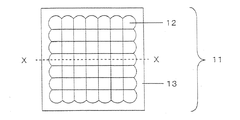
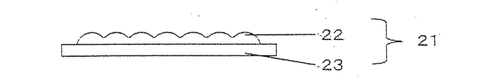
図1は、本発明で用いるレンズアレイの一種であるハエの目レンズの形状を示す平面図である。また、図2は、図1のX−Xにおける断面図を示す。
【0019】
図1のハエの目レンズ(11、21)は、インテグラルフォトグラフィ(IP)や立体テレビなどで用いられる複眼レンズであり、透明な平面板(13、23)の上に凸レンズ(12、22)を敷き詰めた構造になっている。このハエの目レンズの作製方法としては、透明な平面板に凸レンズを敷き詰める他に、金型を作製しての射出成形やプレス成形を用いて作製する方法などが考えられる。
【0020】
本発明に用いるハエの目レンズを構成する凸レンズ(12、22)は、0.1mmから10mm程度のピッチ幅をもつものが好ましく、その倍率は2倍から20倍程度が好ましい。
【0021】
図3はハエの目レンズに対応したドッドパターンを有する表示媒体(30)を説明する概念平面図を示し、レンズアレイの1個のサイズに対応する面積を本明細書ではセルと称することとする。即ち、レンズの縦、横のピッチで囲まれた部分がセルであり、図3(a)では31がセルを示す。
このセル(31)中には複数の画像を構成するドットパターン(32a,32b)を有している。
例えば、図3(a)において32aのドットパターンが「T」の画像を表示するドットパターン、32bのドットパターンが「O」の画像を表示するドットパターンであった場合、図3(b)に示すようにドットパターン表示媒体(30)にハエの目レンズ(11)を重ねて、レンズの焦点を32aのドットパターンに合わせると図4(a)に示す「T」の画像が、ハエの目レンズを移動させ32bのドットパターンにレンズの焦点を合わせると図4(b)に示す「O」の画像が表示される。
【0022】
ドットパターンを構成するドットは、レンズのフォーカスサイズと同程度の大きさで設ける。また、ドットパターンを構成するドットの色は何色でもよく、フルカラーのドットによりドットパターンを形成し、ハエの目レンズを通して見た場合、フルカラーの画像が現れる。
【0023】
図3のセル(31)には、2画像を構成するドットしか示していないが、これ以上の画像のドット数を形成して、レンズアレイを各ドットに重ねることで形成したドット数の画像を表示させることは可能である。
【0024】
また、同一のセルに複数のドットを設けた場合、ハエの目レンズを構成する凸レンズのピッチ内でずらしてドットパターンを設けることにより、複数のドットを同じセルに設けることができる。
これらのドットパターンは、レンズをどれか一つのドットパターンに合わせると、見る角度を変えることにより、他のドットパターンの画像が現れる。このことを利用して、画像が変化するチェンジング、画像が動きを持つアニメーションを実現する。
【0025】
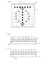
図5は、潜像(隠し絵)を構成しているドットパターンをカモフラージュし、潜像を判別できないようにし偽造、改竄を防止する機能を有するドットパターン表示媒体を説明する図である。
【0026】
図5(a)は、ドット(42)に隣接しドットと補色で、且つドット(42)と等面積を有する領域部分(43)を設けた疑似ドット(41a)を示す。また図5(b)は、41aの疑似ドットとは反対に、42に相当する44の領域には前記疑似ドットの43の色に、43に相当する45の領域には前記ドット(42)の色して、もう一方の疑似ドット(41b)である。
【0027】
上記のような構成の疑似ドット(41a,41b)は、ドットパターンがフルカラー画像であっても遠目には単なる網点にしか見えなく、且つ両者は同じ色調に見えることで区別がつかなく、単に画像構成要素である網点が形成されているとしか認識されず、どのような潜像画像が埋め込まれているか判らなくすることができる。
【0028】
従って、図5(c)のように41aの疑似ドットで画像「T」を潜像(隠し絵)とし、この周辺に41bの疑似ドットを配置させると、どのような潜像(隠し絵)を埋め込ませてあるか肉眼で表示媒体を見た場合、判別が付きにくい。
従って、潜像(隠し絵)が設けられていることが判らないと言う効果が生じ、証券類にドットパターンによる潜像(隠し絵)を設けておくことで偽造、改竄を防ぐことができる。
【0029】
この図5では、ドットの形状及び疑似ドットの形状が矩形で示しているが、円形等どのような形状であってもよいが、通常は矩形、円形が一般的である。
【0030】
上記の図5において、ドットと隣接して異なる色を有する領域部を設けた場合であるが、必ずしもドットと接している必要はなく、離れていても目の解像度より小さい距離であれば、同様な効果が得られる。更に、ドット(42)と領域部分(43)の色を互いに補色関係にすると潜像(隠し絵)が判り難くなる。
【0031】
図6の(a)、(b)はドットパターンを構成するドットのスクリーン線数およびスクリーン角度を変えた例であり、(c)はスクリーン線数を変えたドットにより構成したドットパターンの例である。
ドットは必ずしも、1個の点で形成されている必要はなく、小さな点の集合であっても何ら差支えなく同様な効果が得られる。
【0032】
従って、網点面積率が同じであれば普通にハエの目レンズを通して見た場合には同じ様に見えるが、コピーすると、線数が大きい或いは網点角度によって再現されるドットの濃度が変わる。
このことを利用してスクリーン線数および/もしくはスクリーン角度にドットによって変化させたドットパターンを形成することにより、コピーされたものかどうか識別することができる。
【0033】
すなわち、スクリーン線数が細かな例えば300線/inch以上の網点でドットを形成した場合、複写機では解像できなく潰れてしまい、潰れたドットパターン(特定の画像)が現れる。また、複写機の解像度は方向性によって異なる機種があるので、スクリーン角度を変えることによっても、潰れが生じ同様に潰れたドットパターン(特定の画像)が現れる。
【0034】
また、スクリーン線数及びスクリーン角度とを同時に変えてドットパターンを作製することで、より複製困難になり偽造防止効果を高めることができる。
【0035】
レンズアレイをドットパターンに重ね合わせ、レンズアレイを構成している各レンズの焦点位置とドットの位置が合致すればドットパターンで構成された潜像(隠し絵)を表示できる。しかし、ドットが重なった場合は、重なった部分がノイズとなるので、鮮明に画像を分離して表示させるにはドットが重なり合わないようにした方が良い。
しかし、画像の分離を犠牲にしても、潜像(隠し絵)が埋め込まれていることを第3者に知られないようにカモフラージュし、偽造、改竄を防止する場合には重なり有っていても構わない。
【0036】
このドットパターン表示媒体上にレンズアレイを置き、ドットパターンで構成された潜像(隠し絵)が現れるか否かで真正品であるか、偽造されたものであるか判定でき、有価証券等の偽造防止対策の1手段として利用可能である。
【0037】
また偽造、改竄を防止する方法の他の方法として、通常の絵柄(81)の一部に図8に示すように、ドットの周辺の絵柄、色調と違和感なく溶け込むようにドットパターン(82)を形成しておく。この時に通常の絵柄を構成している網点と重なりあっても良い。
【0038】
また、図7図に示す如く、右目(71)と左目(72)の視差を用いて、ハエの目レンズ(73)を通した場合、別々の視差を有する画像が見えるように右目で見るドットパターン(75)および左目で見るドットパターン(74)を設けることにより、立体画像を現すことができる。
【0039】
ドットパターンは、媒体に印刷により形成することができ、ドットパターンを有する表示媒体を作製することができる。ここで用いる印刷方法としては、オフセット、グラビア、凸版、スクリーンなど既存の印刷技術を用いることができ、媒体は、紙、樹脂フィルム、金属箔など通常印刷に用いる材質のものが挙げられる。
【0040】
また、ドットパターン媒体の形成に情報処理機器に接続したプリンタを用いた場合には、情報処理機器(コンピュータ)で処理され作製された画像のドットパターンを形成した表示媒体を作製することができる。又、ナンバリングされた証券媒体などの番号と関連したドットパターンを形成することにより、セキュリティー性が向上する。
【0041】
本発明で使用するレンズアレイは、2次元に配列した場合はハエの目レンズ、ハニカムレンズであり、1次元に配列した場合はレンチキュラーである。
【0042】
【実施例】
通常の画像中に「T」(82)の文字を矩形ドットとして、「COPY」(83)の文字をスクリーン線数が大きいドットパターンとし、周りの通常の絵柄に溶け込むようにし
たドットで図8に示すような画像をコンピュータ上で作製し、フィルム出力機でY、M、C、K用の4枚のフィルムを作製し、印刷版を作製し、オフセット印刷機を用いて印刷して媒体を得た。
【0043】
このものは、一見、通常の画像であるが、ハエの目レンズを通して見ると、「T」、「COPY」の文字が現れ、潜像媒体として機能した。
また、印刷によって得られた媒体をカラーコピーし、コピーして得られたものは、スクリーン線数の大きなドットで作製された「COPY」のいう文字が潰れて現れて偽造、改竄の牽制媒体として機能した。
【0044】
【発明の効果】
本発明は、上記に記述したように複数のカラー画像を構成するドットを一のセルに設けることで、画像が変化するチェンジング、画像が動きを持つアニメーション画像を実現することができる。また、ドットパターンが視差を有する画像である場合には、立体画像を得ることができる。
【0045】
また、ドットパターンを構成するそれぞれのドットに隣接しドットとは異なる色で、ドットと等面積を有する領域部分を設けた疑似ドットを設け、ドットパターンをカモフラージュすることで、どのような潜像(隠し絵)が埋め込まれているか判らなくしているので、偽造、改竄等が困難となる。従って、有価証券と偽造防止対策に有効な手段となる。
【0046】
また、通常の絵柄の一部に本発明のドットパターンを通常の絵柄と違和感なく埋め込むことで、どのような潜像(隠し絵)が埋め込まれているか判らなくしているので、偽造、改竄等が困難となる。従って、有価証券と偽造防止対策に有効な手段となる。
【0047】
また、ドットパターン表示媒体にレンズアレイを置き、特定の画像が現れるか否かによって真偽判定ができ、更に複製する場合解像できないようなスクリーン線数或いはスクリーン角度でドットパターンを形成することで偽造、改竄防止の効果が生じる。
【図面の簡単な説明】
【図1】 本発明で用いるハエの目レンズの平面図である。
【図2】 図1のX−Xにおける断面図である。
【図3】 ドットパターンおよびドットパターンにハエの目レンズを通したときに現れる画像を説明するものであり、
(a)は、ドットパターンを有する表示媒体の平面図、
(b),(c)は、表示媒体の各ドットに焦点を合わせた場合を説明する断面図
である。
【図4】 図3に於ける1のドットに焦点を合わせて場合に表示される像を示し、
(a)は、「T」の画像を構成するドットに焦点を合わせた場合、(b)は「O」の画像を構成するドットに焦点を合わせた場合に表示される像を示す。
【図5】 ドットパターンを構成するドットに隣接し、ドットとは異なる色で、ドットと等面積を有する領域部分を設けた疑似ドットを用いたドットパターンを有する表示媒体を説明するものであり、
(a)、(b)は疑似ドットを、(c)はこの疑似ドットを有する表示媒体の概念平面図である。
【図6】 スクリーン線数およびスクリーン角度を変えたドットおよびドットパターンを説明するものであり、
(a)、(b)はスクリーン線数およびスクリーン角度を変えたドットを、(c)は、このドットを有する表示媒体の概念平面図である。
【図7】 右目と左目の視差を用いて立体画像を表示する場合を説明する模式図である。
【図8】 通常の画像中にドットパターンを形成した一例を示す平面図である。
【図9】 従来の潜像パターンを設ける方法を説明するものであり、
(a)はスクリーン角度を変えて潜像を設けた概略平面図、
(b)はモアレを生じさせるためのフィルムの概略平面図、
(c)は(a)に(b)を重ねた時にモアレによって生じた潜像を示す概略平面図、
をそれぞれ示す。
【符号の説明】
11…ハエの目レンズ
12…凸レンズ
13…透明な平面版
21…ハエの目レンズ
22…凸レンズ
23…透明な平面版
30…表示媒体
31…セル
32a,32b…ドットパターン
40…表示媒体
41a,41b…疑似ドット
42…ドット
50…表示媒体
71…右目
72…左目
74…右目で見るドットパターン
75…左目で見るドットパターン
80…表示媒体
81…通常の画像
82…ドットパターン潜像
83…スクリーン線数が大きいドットパターン潜像
91…隠しパターン(潜像)
92…フィルム
93…モワレにより現れた隠しパターン[0001]
BACKGROUND OF THE INVENTION
The present invention provides a display medium having a dot pattern for displaying images such as changing images, animation, and stereo for use in hidden pictures and play by lens arrays such as fly-eye lenses and lenticulars. The present invention relates to a dot pattern display medium having an effect of improving a latent image and copy restraint, and a manufacturing method thereof.
[0002]
[Prior art]
Conventionally, as a method of concealing a pattern such as a character in a picture, there is a method of changing a screen angle of a halftone dot constituting a printed picture only at a portion forming the pattern as shown in FIG. When a film (92) in which halftone dots are formed is applied to the pattern, a technique is used in which a portion having the same screen angle causes moire and a hidden pattern (93) appears.
However, with this method, the number of images that can be placed in the same place is limited, and the color is limited to a single color.
[0003]
[Problems to be solved by the invention]
Therefore, when a plurality of color images are formed as a latent image in a dot pattern and the lens array is aligned, a dot pattern display medium that can display the latent image, and when a display medium having this dot pattern is copied, It is an object to provide a display medium that can be detected and has a function of preventing forgery and tampering.
Another object of the present invention is to determine the authenticity of securities and prevent duplication using the above functions.
[0004]
[Means for Solving the Problems]
The invention made in order to solve the above-mentioned problems in the present invention provides a dot pattern composed of dots of at least two kinds of colors having the same pitch as the lens pitch of the lens array, and the image is obtained by overlapping the lens arrays. This is based on a dot pattern display medium characterized by providing a dot pattern that appears.
[0005]
First, the invention according to claim 1 is provided with a complementary color region portion adjacent to each dot constituting a dot pattern composed of dots of at least two kinds of colors having the same pitch in the periphery and having the same area as the dots. It is composed of dots of at least two kinds of colors with the same pitch, which are different from the dot pattern, adjacent to each dot constituting the dot pattern in which an image appears by overlapping the same lens array as the pitch, and has the same area as the dot. This is a dot pattern display medium in which a dot pattern provided with a complementary color region is provided as a latent image .
Further, the invention according to
[0006]
According to a third aspect of the present invention, there is provided a complementary color region portion adjacent to each dot constituting a dot pattern composed of dots of at least two kinds of colors having the same pitch at the periphery, and having the same area as the dots. Different dot patterns, consisting of dots of at least two types of colors with the same pitch, and by overlapping the same lens array with the pitch, an area equal to the dots is formed in the vicinity of each dot constituting the dot pattern that appears. A dot pattern display medium comprising a dot pattern provided with a complementary color region as a latent image .
According to a fourth aspect of the present invention, there is provided a dot pattern in which an image appears by overlapping a lens array having the same pitch as that of a dot having at least two kinds of colors having the same pitch on a part of a normal image. This is a dot pattern display medium in which a dot pattern in which a complementary color region having the same area as a dot is provided as a latent image in the vicinity of each dot.
[0007]
According to a fifth aspect of the present invention, in the dot pattern according to any one of the first to fourth aspects , each dot constituting the dot pattern is composed of at least two types of screen lines. It is a display medium.
[0008]
According to a sixth aspect of the present invention, in the dot pattern display according to any one of the first to fourth aspects , each dot constituting the dot pattern is composed of halftone dots having at least two types of screen angles. It is a medium.
[0009]
The invention described in claim 7 is characterized in that each dot constituting the dot pattern is composed of at least two types of screen lines and at least two types of screen angle halftone dots. To 4. The dot pattern display medium according to any one of 4 to 4 .
[0010]
The invention according to claim 8 is the dot pattern according to any one of claims 1 to 7 , wherein the dots constituting the dot pattern are formed so as not to overlap each other. It is a display medium.
[0011]
The invention according to claim 9 is characterized in that when the dot pattern is passed through a lens array having the same pitch as the dot pitch, the right eye and the left eye are arranged so that images having different parallaxes can be seen. The dot pattern display medium according to any one of 1 to 8 .
[0012]
[0013]
The invention according to claim 10 is the production of the dot pattern display medium according to any one of claims 1 to 9 using printing or a printer. Is the method.
[0014]
The invention of claim 1 1, wherein, in the manufacturing method of claim 10, wherein the Dodd pattern display medium, comprising at least two kinds of colored dots of the same pitch at least a portion of the ordinary image represented by the dot pattern, A method for producing a dot pattern display medium, comprising the step of changing to a dot pattern in which an image appears by overlapping lens arrays having the same pitch.
[0015]
[0016]
[0017]
In general, dot and halftone are synonyms. However, in this specification, in order to make the invention easy to understand, the dots are the components (area) of the image displayed when the lens array of the present invention is overlaid, and the halftone dots are in the printing field. It refers to a normal point that is defined and is expressed separately. That is, the halftone dots are gathered to form one image constituent element, and the block is also called a dot.
[0018]
DETAILED DESCRIPTION OF THE INVENTION
Hereinafter, embodiments of the present invention will be described in detail with reference to the drawings.
FIG. 1 is a plan view showing the shape of a fly-eye lens which is a kind of lens array used in the present invention. 2 shows a cross-sectional view taken along the line XX of FIG.
[0019]
The fly-eye lenses (11, 21) in FIG. 1 are compound eye lenses used in integral photography (IP), stereoscopic televisions, etc., and convex lenses (12, 22) on transparent flat plates (13, 23). ). As a method for manufacturing the fly-eye lens, in addition to spreading a convex lens on a transparent flat plate, a method of manufacturing a mold using injection molding or press molding may be considered.
[0020]
The convex lenses (12, 22) constituting the fly-eye lens used in the present invention preferably have a pitch width of about 0.1 mm to 10 mm, and the magnification is preferably about 2 to 20 times.
[0021]
FIG. 3 is a conceptual plan view illustrating a display medium (30) having a dod pattern corresponding to a fly-eye lens, and an area corresponding to one size of the lens array is referred to as a cell in this specification. . That is, the portion surrounded by the vertical and horizontal pitches of the lens is a cell, and 31 in FIG.
This cell (31) has dot patterns (32a, 32b) constituting a plurality of images.
For example, in FIG. 3A, when the dot pattern of 32a is a dot pattern that displays an image of “T”, and the dot pattern of 32b is a dot pattern that displays an image of “O”, FIG. When the fly-eye lens (11) is overlapped on the dot pattern display medium (30) and the focus of the lens is adjusted to the dot pattern of 32a, as shown in FIG. 4A, an image of “T” shown in FIG. When the lens is moved and the lens is focused on the dot pattern of 32b, an “O” image shown in FIG. 4B is displayed.
[0022]
The dots constituting the dot pattern are provided with the same size as the lens focus size. Further, the dot pattern may have any number of colors. When the dot pattern is formed by full-color dots and viewed through a fly-eye lens, a full-color image appears.
[0023]
In the cell (31) of FIG. 3, only the dots constituting the two images are shown, but an image of the number of dots formed by forming the number of dots of the image larger than this and overlaying the lens array on each dot is shown. It is possible to display.
[0024]
Further, when a plurality of dots are provided in the same cell, a plurality of dots can be provided in the same cell by providing a dot pattern that is shifted within the pitch of the convex lens constituting the fly-eye lens.
In these dot patterns, when the lens is matched with any one dot pattern, an image of another dot pattern appears by changing the viewing angle. Utilizing this fact, it is possible to realize changing with changing images and animation with moving images.
[0025]
FIG. 5 is a diagram for explaining a dot pattern display medium having a function of camouflaging a dot pattern constituting a latent image (hidden picture) so that the latent image cannot be discriminated and preventing forgery and alteration.
[0026]
FIG. 5A shows a pseudo dot (41a) that is adjacent to the dot (42) and has a region portion (43) that is complementary to the dot and has the same area as the dot (42). FIG. 5B shows, in contrast to the pseudo dots of 41a, 44 colors corresponding to 42 in the 43 colors of the pseudo dots, and 45 areas corresponding to 43 of the dots (42). Colored is the other pseudo dot (41b).
[0027]
The pseudo dots (41a, 41b) having the above-described configuration can only be seen as a halftone dot in the distance even if the dot pattern is a full-color image, and both are indistinguishable because they appear in the same color tone. Only a halftone dot that is an image component is recognized, and it is not possible to know what latent image is embedded.
[0028]
Accordingly, as shown in FIG. 5C, when the image “T” is made a latent image (hidden picture) with the
Therefore, there is an effect that it is not known that a latent image (hidden picture) is provided, and forgery and tampering can be prevented by providing a latent image (hidden picture) with a dot pattern in securities.
[0029]
In FIG. 5, the shape of the dot and the shape of the pseudo dot are shown as rectangles. However, any shape such as a circle may be used, but a rectangle or a circle is generally used.
[0030]
In FIG. 5 described above, a region portion having a different color is provided adjacent to the dot, but it is not necessarily in contact with the dot. Effects can be obtained. Furthermore, if the colors of the dot (42) and the area portion (43) are complementary to each other, the latent image (hidden picture) becomes difficult to understand.
[0031]
6A and 6B are examples in which the number of screen lines and the screen angle of the dots constituting the dot pattern are changed, and FIG. 6C is an example of a dot pattern constituted by dots in which the number of screen lines is changed. is there.
The dots are not necessarily formed by one point, and the same effect can be obtained without any problem even if the dots are a set of small points.
[0032]
Therefore, if the halftone dot area ratio is the same, it looks the same when viewed through a fly-eye lens. However, when copied, the number of lines is large or the density of the reproduced dot varies depending on the halftone dot angle.
By making use of this fact, a dot pattern in which the number of screen lines and / or the screen angle is changed by dots is formed, so that it is possible to identify whether or not it has been copied.
[0033]
That is, when dots are formed with a halftone dot of, for example, 300 lines / inch or more where the number of screen lines is fine, the image cannot be resolved by the copying machine, and a broken dot pattern (specific image) appears. In addition, since the resolution of the copying machine varies depending on the directionality, the dot pattern (specific image) appears in the same manner even when the screen angle is changed.
[0034]
In addition, by creating a dot pattern by simultaneously changing the number of screen lines and the screen angle, it becomes more difficult to duplicate and the forgery prevention effect can be enhanced.
[0035]
If the lens array is superimposed on the dot pattern and the focal position of each lens constituting the lens array matches the dot position, a latent image (hidden picture) composed of the dot pattern can be displayed. However, when the dots overlap, the overlapped portion becomes noise, so it is better to prevent the dots from overlapping each other in order to clearly separate and display the image.
However, even if image separation is sacrificed, it is overlapped when camouflaging so that a third party does not know that a latent image (hidden picture) is embedded, and preventing forgery and tampering. It doesn't matter.
[0036]
A lens array is placed on this dot pattern display medium, and it can be determined whether it is genuine or counterfeit depending on whether or not a latent image (hidden picture) composed of dot patterns appears. It can be used as a means for preventing counterfeiting.
[0037]
As another method for preventing forgery and alteration, as shown in FIG. 8, a dot pattern (82) is blended into a part of a normal pattern (81) so as to blend with the pattern and color tone around the dot without any sense of incongruity. Form it. At this time, it may overlap with halftone dots constituting a normal picture.
[0038]
Further, as shown in FIG. 7, when the parallax of the right eye (71) and the left eye (72) is used and the fly-eye lens (73) is passed through, the dots viewed by the right eye so that an image having different parallax can be seen. By providing the pattern (75) and the dot pattern (74) viewed with the left eye, a stereoscopic image can be displayed.
[0039]
The dot pattern can be formed on a medium by printing, and a display medium having the dot pattern can be manufactured. As the printing method used here, existing printing techniques such as offset, gravure, letterpress, and screen can be used, and examples of the medium include materials used for normal printing such as paper, resin film, and metal foil.
[0040]
In addition, when a printer connected to an information processing device is used for forming the dot pattern medium, a display medium on which a dot pattern of an image processed and manufactured by the information processing device (computer) is formed can be manufactured. Further, by forming a dot pattern associated with the number of the numbered securities medium or the like, security is improved.
[0041]
The lens array used in the present invention is a fly-eye lens or a honeycomb lens when arranged two-dimensionally, and a lenticular when arranged one-dimensionally.
[0042]
【Example】
In the normal image, the character “T” (82) is a rectangular dot, the character “COPY” (83) is a dot pattern having a large screen line number, and the dots are mixed with the surrounding normal pattern as shown in FIG. An image as shown in Fig. 4 is produced on a computer, four films for Y, M, C, and K are produced with a film output machine, a printing plate is produced, and printing is performed using an offset printing machine. Obtained.
[0043]
At first glance, this was a normal image, but when viewed through a fly's eye lens, the characters “T” and “COPY” appeared and functioned as a latent image medium.
In addition, the media obtained by printing is color-copied, and what is obtained by copying is a check medium for counterfeiting and falsification that appears as the characters “COPY” made with dots with a large number of screen lines collapse. It worked.
[0044]
【The invention's effect】
In the present invention, as described above, by providing dots constituting a plurality of color images in one cell, it is possible to realize a changing image in which the image changes and an animation image in which the image moves. In addition, when the dot pattern is an image having parallax, a stereoscopic image can be obtained.
[0045]
In addition, by providing a pseudo dot that is adjacent to each dot constituting the dot pattern and has a different area from the dot and having an area equal to the dot, and camouflaging the dot pattern, any latent image ( It is difficult to forge or falsify because it is not known whether the (hidden picture) is embedded. Therefore, it becomes an effective means for securities and counterfeiting prevention measures.
[0046]
In addition, by embedding the dot pattern of the present invention in a part of the normal pattern without any sense of incongruity with the normal pattern, it is not possible to know what latent image (hidden picture) is embedded. It becomes difficult. Therefore, it becomes an effective means for securities and counterfeiting prevention measures.
[0047]
In addition, by placing a lens array on a dot pattern display medium and making a true / false judgment based on whether or not a specific image appears, and forming a dot pattern with a screen line number or screen angle that cannot be resolved when copying. This has the effect of preventing counterfeiting and tampering.
[Brief description of the drawings]
FIG. 1 is a plan view of a fly-eye lens used in the present invention.
FIG. 2 is a cross-sectional view taken along the line XX of FIG.
FIG. 3 illustrates a dot pattern and an image that appears when a fly-eye lens is passed through the dot pattern;
(A) is a plan view of a display medium having a dot pattern;
(B), (c) is sectional drawing explaining the case where each dot of a display medium is focused.
4 shows an image displayed when focusing on one dot in FIG. 3,
(A) shows an image displayed when focusing on the dots constituting the “T” image, and (b) shows an image displayed when focusing on the dots constituting the “O” image.
FIG. 5 illustrates a display medium having a dot pattern using pseudo dots that are adjacent to the dots constituting the dot pattern and are provided with a region portion having an area equal to the dots in a color different from the dots;
(A), (b) is a pseudo | simulation dot, (c) is a conceptual top view of the display medium which has this pseudo dot.
FIG. 6 is a diagram for explaining dots and dot patterns with different screen line numbers and screen angles;
(A), (b) is the dot which changed the screen line number and the screen angle, (c) is a conceptual top view of the display medium which has this dot.
FIG. 7 is a schematic diagram illustrating a case where a stereoscopic image is displayed using parallax of the right eye and the left eye.
FIG. 8 is a plan view showing an example in which a dot pattern is formed in a normal image.
FIG. 9 illustrates a conventional method of providing a latent image pattern;
(A) is a schematic plan view in which a latent image is provided by changing the screen angle;
(B) is a schematic plan view of a film for generating moire,
(C) is a schematic plan view showing a latent image generated by moire when (b) is superimposed on (a),
Respectively.
[Explanation of symbols]
DESCRIPTION OF
92 ...
Claims (11)
Priority Applications (1)
| Application Number | Priority Date | Filing Date | Title |
|---|---|---|---|
| JP2000143284A JP4013450B2 (en) | 2000-05-16 | 2000-05-16 | Dot pattern display medium and manufacturing method thereof |
Applications Claiming Priority (1)
| Application Number | Priority Date | Filing Date | Title |
|---|---|---|---|
| JP2000143284A JP4013450B2 (en) | 2000-05-16 | 2000-05-16 | Dot pattern display medium and manufacturing method thereof |
Publications (2)
| Publication Number | Publication Date |
|---|---|
| JP2001324949A JP2001324949A (en) | 2001-11-22 |
| JP4013450B2 true JP4013450B2 (en) | 2007-11-28 |
Family
ID=18650125
Family Applications (1)
| Application Number | Title | Priority Date | Filing Date |
|---|---|---|---|
| JP2000143284A Expired - Fee Related JP4013450B2 (en) | 2000-05-16 | 2000-05-16 | Dot pattern display medium and manufacturing method thereof |
Country Status (1)
| Country | Link |
|---|---|
| JP (1) | JP4013450B2 (en) |
Cited By (3)
| Publication number | Priority date | Publication date | Assignee | Title |
|---|---|---|---|---|
| CN102725148A (en) * | 2009-07-09 | 2012-10-10 | Ovd基尼格拉姆股份公司 | Multilayer |
| US8876167B2 (en) | 2008-10-03 | 2014-11-04 | National Printing Bureau, Incorporated Administrative Agency | Anti-counterfeit printed matter |
| US8985634B2 (en) | 2008-09-16 | 2015-03-24 | National Printing Bureau, Incorporated Administrative Agency | Anti-counterfeit printed matter, method of manufacturing the same, and recording medium storing halftone dot data creation software |
Families Citing this family (28)
| Publication number | Priority date | Publication date | Assignee | Title |
|---|---|---|---|---|
| AU2002952371A0 (en) * | 2002-10-31 | 2002-11-14 | Robert Van Der Zijpp | Mutli Image to Merged Image Software Process |
| US8867134B2 (en) | 2003-11-21 | 2014-10-21 | Visual Physics, Llc | Optical system demonstrating improved resistance to optically degrading external effects |
| JP2006051646A (en) * | 2004-08-11 | 2006-02-23 | National Printing Bureau | Authentic printed material |
| JP4800302B2 (en) * | 2005-04-11 | 2011-10-26 | 日本カーバイド工業株式会社 | Retroreflective sheet with printed image |
| KR101265368B1 (en) * | 2005-05-18 | 2013-05-20 | 비쥬얼 피직스 엘엘씨 | Image presentation and micro-optic security system |
| JP2007068032A (en) | 2005-09-01 | 2007-03-15 | Ricoh Co Ltd | Image display medium, synthetic image display data creation method, and image generation system |
| JP4649612B2 (en) * | 2005-11-25 | 2011-03-16 | 独立行政法人 国立印刷局 | Authentic printed material |
| CN1888949A (en) * | 2006-07-12 | 2007-01-03 | 张华升 | Hidden image identifying system, products, identifying device and producing method |
| JP4635160B2 (en) * | 2007-09-03 | 2011-02-16 | 独立行政法人 国立印刷局 | Anti-counterfeit printed matter |
| JP6110068B2 (en) * | 2009-03-04 | 2017-04-05 | イノヴィア セキュリティー プロプライアタリー リミテッド | Improvement of lens array fabrication method |
| JP2011025557A (en) * | 2009-07-27 | 2011-02-10 | Dainippon Printing Co Ltd | Printed matter and authenticity verification method for printed matter |
| WO2011019912A1 (en) | 2009-08-12 | 2011-02-17 | Visual Physics, Llc | A tamper indicating optical security device |
| JP2011173267A (en) * | 2010-02-23 | 2011-09-08 | Toppan Printing Co Ltd | Id card and card case |
| WO2012103441A1 (en) | 2011-01-28 | 2012-08-02 | Crane & Co., Inc | A laser marked device |
| JP2014524600A (en) | 2011-08-19 | 2014-09-22 | ビジュアル フィジクス エルエルシー | Optical system capable of transfer on demand with reduced thickness |
| JP2014526711A (en) * | 2012-06-12 | 2014-10-06 | メディア レリーフ | Method for creating an iridescent image, the resulting image, a device with the iridescent image, and an associated program |
| RU2621558C9 (en) | 2012-08-17 | 2017-12-05 | Визуал Физикс, Ллс | Process of transfering microstructures on final substrate |
| JP6061192B2 (en) * | 2013-02-12 | 2017-01-18 | 独立行政法人 国立印刷局 | Three-dimensional display formed body and method for producing the same |
| BR112015022369A2 (en) * | 2013-03-15 | 2017-07-18 | Visual Physics Llc | optical safety device |
| US9873281B2 (en) | 2013-06-13 | 2018-01-23 | Visual Physics, Llc | Single layer image projection film |
| US10766292B2 (en) | 2014-03-27 | 2020-09-08 | Crane & Co., Inc. | Optical device that provides flicker-like optical effects |
| KR102385592B1 (en) | 2014-03-27 | 2022-04-11 | 비쥬얼 피직스 엘엘씨 | An optical device that produces flicker-like optical effects |
| ES3014185T3 (en) | 2014-07-17 | 2025-04-21 | Visual Physics Llc | An improved polymeric sheet material for use in making polymeric security documents such as bank notes |
| EP3194180B1 (en) | 2014-09-16 | 2025-05-07 | Crane Security Technologies, Inc. | Secure lens layer |
| KR102693122B1 (en) | 2015-02-11 | 2024-08-08 | 크레인 앤 코, 인크 | Method for applying a security device to a surface of a substrate |
| WO2018147966A1 (en) | 2017-02-10 | 2018-08-16 | Crane & Co., Inc. | Machine-readable optical security device |
| JP2019045791A (en) * | 2017-09-06 | 2019-03-22 | 凸版印刷株式会社 | Anti-counterfeit medium, production method thereof, and dot pattern display method |
| JP7251134B2 (en) * | 2018-12-21 | 2023-04-04 | 凸版印刷株式会社 | Anti-counterfeit medium, display method and method for producing the same |
-
2000
- 2000-05-16 JP JP2000143284A patent/JP4013450B2/en not_active Expired - Fee Related
Cited By (3)
| Publication number | Priority date | Publication date | Assignee | Title |
|---|---|---|---|---|
| US8985634B2 (en) | 2008-09-16 | 2015-03-24 | National Printing Bureau, Incorporated Administrative Agency | Anti-counterfeit printed matter, method of manufacturing the same, and recording medium storing halftone dot data creation software |
| US8876167B2 (en) | 2008-10-03 | 2014-11-04 | National Printing Bureau, Incorporated Administrative Agency | Anti-counterfeit printed matter |
| CN102725148A (en) * | 2009-07-09 | 2012-10-10 | Ovd基尼格拉姆股份公司 | Multilayer |
Also Published As
| Publication number | Publication date |
|---|---|
| JP2001324949A (en) | 2001-11-22 |
Similar Documents
| Publication | Publication Date | Title |
|---|---|---|
| JP4013450B2 (en) | Dot pattern display medium and manufacturing method thereof | |
| JP4495824B2 (en) | Information processing method | |
| US5924870A (en) | Lenticular image and method | |
| US7845572B2 (en) | Solid-color embedded security feature | |
| JPH0793503A (en) | Anti-counterfeiting method using micro-convex lenticular optics and color masking | |
| JP2010217886A (en) | High resolution scalable gloss effect | |
| MX2008014176A (en) | Security enhanced print media with copy protection. | |
| JP2020089971A (en) | Anti-counterfeit printed matter, method of manufacturing data for anti-counterfeit printed matter, and manufacturing system for anti-counterfeit printed matter | |
| JPS60645B2 (en) | Password formation using moiré effect | |
| US20060129823A1 (en) | Security device | |
| JP5652789B2 (en) | 3D printed material | |
| JP3686953B2 (en) | Anti-counterfeit printed matter and its production method | |
| JP5365133B2 (en) | Image forming body and image making method | |
| JP4411399B2 (en) | Authenticity discriminator | |
| JP4415542B2 (en) | Printed material having latent image and method for visualizing the same | |
| JP2014117892A (en) | Printed matter prevented from being duplicated or falsified | |
| JP6112357B2 (en) | Anti-counterfeit latent image display structure | |
| JP2011189690A (en) | Forgery preventing printed matter | |
| JPH0725130A (en) | Front and back pattern composite printed material in which latent image appears as color image and method for producing the same | |
| KR101470619B1 (en) | Print media Applied to the security element and method. | |
| JP4595068B2 (en) | Authentic printed material | |
| JP3840944B2 (en) | Information recording medium having encrypted information | |
| JP7352232B2 (en) | Copy check prints and methods for creating copy check prints | |
| JP2007068032A (en) | Image display medium, synthetic image display data creation method, and image generation system | |
| JP2021011098A (en) | Copy prevention sheet and manufacturing method thereof |
Legal Events
| Date | Code | Title | Description |
|---|---|---|---|
| A621 | Written request for application examination |
Free format text: JAPANESE INTERMEDIATE CODE: A621 Effective date: 20040318 |
|
| A977 | Report on retrieval |
Free format text: JAPANESE INTERMEDIATE CODE: A971007 Effective date: 20050929 |
|
| A131 | Notification of reasons for refusal |
Free format text: JAPANESE INTERMEDIATE CODE: A131 Effective date: 20051101 |
|
| A521 | Request for written amendment filed |
Free format text: JAPANESE INTERMEDIATE CODE: A523 Effective date: 20051227 |
|
| A521 | Request for written amendment filed |
Free format text: JAPANESE INTERMEDIATE CODE: A523 Effective date: 20051227 |
|
| A131 | Notification of reasons for refusal |
Free format text: JAPANESE INTERMEDIATE CODE: A131 Effective date: 20061010 |
|
| A521 | Request for written amendment filed |
Free format text: JAPANESE INTERMEDIATE CODE: A523 Effective date: 20061207 |
|
| A02 | Decision of refusal |
Free format text: JAPANESE INTERMEDIATE CODE: A02 Effective date: 20070123 |
|
| A521 | Request for written amendment filed |
Free format text: JAPANESE INTERMEDIATE CODE: A523 Effective date: 20070323 |
|
| A911 | Transfer to examiner for re-examination before appeal (zenchi) |
Free format text: JAPANESE INTERMEDIATE CODE: A911 Effective date: 20070404 |
|
| A131 | Notification of reasons for refusal |
Free format text: JAPANESE INTERMEDIATE CODE: A131 Effective date: 20070612 |
|
| A521 | Request for written amendment filed |
Free format text: JAPANESE INTERMEDIATE CODE: A523 Effective date: 20070727 |
|
| TRDD | Decision of grant or rejection written | ||
| A01 | Written decision to grant a patent or to grant a registration (utility model) |
Free format text: JAPANESE INTERMEDIATE CODE: A01 Effective date: 20070821 |
|
| A61 | First payment of annual fees (during grant procedure) |
Free format text: JAPANESE INTERMEDIATE CODE: A61 Effective date: 20070903 |
|
| FPAY | Renewal fee payment (event date is renewal date of database) |
Free format text: PAYMENT UNTIL: 20100921 Year of fee payment: 3 |
|
| R150 | Certificate of patent or registration of utility model |
Free format text: JAPANESE INTERMEDIATE CODE: R150 |
|
| FPAY | Renewal fee payment (event date is renewal date of database) |
Free format text: PAYMENT UNTIL: 20110921 Year of fee payment: 4 |
|
| FPAY | Renewal fee payment (event date is renewal date of database) |
Free format text: PAYMENT UNTIL: 20110921 Year of fee payment: 4 |
|
| FPAY | Renewal fee payment (event date is renewal date of database) |
Free format text: PAYMENT UNTIL: 20120921 Year of fee payment: 5 |
|
| FPAY | Renewal fee payment (event date is renewal date of database) |
Free format text: PAYMENT UNTIL: 20120921 Year of fee payment: 5 |
|
| FPAY | Renewal fee payment (event date is renewal date of database) |
Free format text: PAYMENT UNTIL: 20130921 Year of fee payment: 6 |
|
| LAPS | Cancellation because of no payment of annual fees |