JP5494571B2 - Fuel property determination device and catalyst abnormality diagnosis device provided with the same - Google Patents
Fuel property determination device and catalyst abnormality diagnosis device provided with the same Download PDFInfo
- Publication number
- JP5494571B2 JP5494571B2 JP2011119411A JP2011119411A JP5494571B2 JP 5494571 B2 JP5494571 B2 JP 5494571B2 JP 2011119411 A JP2011119411 A JP 2011119411A JP 2011119411 A JP2011119411 A JP 2011119411A JP 5494571 B2 JP5494571 B2 JP 5494571B2
- Authority
- JP
- Japan
- Prior art keywords
- catalyst
- downstream
- fuel
- temperature
- upstream
- Prior art date
- Legal status (The legal status is an assumption and is not a legal conclusion. Google has not performed a legal analysis and makes no representation as to the accuracy of the status listed.)
- Expired - Fee Related
Links
Images


Description
本発明は、内燃機関の使用燃料の燃料性状を判定する燃料性状判定装置及びこれを備えた触媒異常診断装置に係り、特に、内燃機関の使用燃料の硫黄濃度を推定可能な燃料性状判定装置及びこれを備えた触媒異常診断装置に関する。 The present invention relates to a fuel property determination device that determines the fuel property of fuel used in an internal combustion engine and a catalyst abnormality diagnosis device equipped with the fuel property determination device, and in particular, a fuel property determination device that can estimate the sulfur concentration of fuel used in an internal combustion engine and The present invention relates to a catalyst abnormality diagnosis apparatus provided with this.
例えば自動車用内燃機関において、その排気系には排気ガスを浄化するための触媒が設置されている。この触媒の中には酸素吸蔵能(O2ストレージ能)を有するものがある。この酸素吸蔵能を有する触媒は、触媒に流入する排気ガスの空燃比が理論空燃比(ストイキ)よりも大きくなると、即ちリーンになると排気ガス中に存在する過剰酸素を吸蔵し、排気ガスの空燃比がストイキよりも小さくなると、即ちリッチになると吸蔵した酸素を放出する。例えばガソリンエンジンでは触媒に流入する排気ガスがストイキ近傍となるよう空燃比制御が行われるが、酸素吸蔵能を有する三元触媒を使用すると、運転条件により実際の空燃比がストイキから多少ズレてしまっても、三元触媒の酸素吸蔵・放出作用により、かかる空燃比ズレを吸収することができる。 For example, in an internal combustion engine for automobiles, a catalyst for purifying exhaust gas is installed in the exhaust system. Some of these catalysts have an oxygen storage capacity (O 2 storage capacity). When the air-fuel ratio of the exhaust gas flowing into the catalyst becomes larger than the stoichiometric air-fuel ratio (stoichiometric), that is, when the engine becomes lean, the catalyst having oxygen storage capacity occludes excess oxygen present in the exhaust gas. When the fuel ratio becomes smaller than stoichiometric, that is, when it becomes rich, the stored oxygen is released. For example, in a gasoline engine, air-fuel ratio control is performed so that the exhaust gas flowing into the catalyst is in the vicinity of the stoichiometric. However, if a three-way catalyst having an oxygen storage capacity is used, the actual air-fuel ratio slightly deviates from the stoichiometric depending on the operating conditions. However, such an air-fuel ratio shift can be absorbed by the oxygen storage / release action of the three-way catalyst.
一方、触媒が劣化すると触媒の浄化率が低下する。触媒の劣化度と酸素吸蔵能の低下度との間には相関関係がある。よって、酸素吸蔵能の低下を検出することで触媒の劣化ないし異常を検出することができる。一般的には、空燃比をリッチ及びリーンに交互に切り替えるアクティブ空燃比制御を行い、触媒の酸素吸蔵容量を計測し、触媒の劣化を診断する方法(所謂Cmax法)が採用される。 On the other hand, when the catalyst deteriorates, the purification rate of the catalyst decreases. There is a correlation between the deterioration degree of the catalyst and the reduction degree of the oxygen storage capacity. Therefore, it is possible to detect deterioration or abnormality of the catalyst by detecting a decrease in oxygen storage capacity. In general, a method (so-called Cmax method) that performs active air-fuel ratio control that alternately switches the air-fuel ratio between rich and lean, measures the oxygen storage capacity of the catalyst, and diagnoses deterioration of the catalyst is employed.
ところで、使用地域等によっては燃料中に硫黄(S)が比較的高濃度で含まれていることがある。このような高硫黄燃料が給油された場合、排気ガス中の硫黄成分の影響により、触媒が硫黄被毒(S被毒)することがある。S被毒が発生すると、触媒の酸素吸放出作用が妨げられて触媒の見掛け上の酸素吸蔵容量が低下する。しかしながら、硫黄濃度の低い燃料が再度給油されたり、高温且つリッチな雰囲気に触媒が曝されたりすると、被毒状態は解消する。 By the way, depending on a use area etc., sulfur (S) may be contained in fuel by comparatively high concentration. When such a high sulfur fuel is supplied, the catalyst may be sulfur poisoned (S poison) due to the influence of the sulfur component in the exhaust gas. When S poisoning occurs, the oxygen storage / release action of the catalyst is hindered, and the apparent oxygen storage capacity of the catalyst decreases. However, when the fuel with a low sulfur concentration is refueled or the catalyst is exposed to a high temperature and rich atmosphere, the poisoning state is eliminated.
S被毒による触媒の性能低下は一時的且つ回復可能なものである。よって触媒の異常診断においては、かかるS被毒による一時的異常を、本来診断すべき回復不能な恒久的異常(熱劣化)と誤って診断しないようにする必要がある。 The catalyst performance degradation due to S poisoning is temporary and recoverable. Therefore, in the abnormality diagnosis of the catalyst, it is necessary not to mistakenly diagnose the temporary abnormality due to the S poisoning as an unrecoverable permanent abnormality (thermal deterioration) that should be diagnosed.
例えば特許文献1に記載の装置では、前記Cmax法により触媒の吸蔵酸素量を計測すると共に、所定条件が成立した場合に空燃比をリッチからリーンに切り替えるタイミングを遅らせて再度吸蔵酸素量を計測する。そしてこれら計測値に基づき前者の計測値を補正し、計測値を低硫黄燃料使用時相当の値に補正した上で劣化診断する。
For example, in the apparatus described in
上記誤診断を防止するためには、燃料性状、特に燃料の硫黄濃度を推定ないし判定するのが好適である。かかる推定ないし判定を行えば、燃料が高硫黄濃度であると判定したときに必要な措置を執ることができ、誤診断を未然に防止できるからである。 In order to prevent the above-mentioned misdiagnosis, it is preferable to estimate or determine the fuel properties, particularly the sulfur concentration of the fuel. This is because if such estimation or determination is performed, necessary measures can be taken when it is determined that the fuel has a high sulfur concentration, and erroneous diagnosis can be prevented.
そこで本発明はこのような実情に鑑みてなされたもので、その目的は、燃料の硫黄濃度を好適に推定することができる燃料性状判定装置、及びこれを備えた触媒異常診断装置を提供することにある。 Therefore, the present invention has been made in view of such circumstances, and an object thereof is to provide a fuel property determination device that can suitably estimate the sulfur concentration of fuel, and a catalyst abnormality diagnosis device including the same. It is in.
本発明の第1の態様によれば、
内燃機関の排気通路の上流側および下流側にそれぞれ設けられた上流触媒および下流触媒と、
これら上流触媒および下流触媒の劣化度を表す指標値をそれぞれ計測する計測手段と、
前記計測手段によって計測された前記上流触媒の指標値に基づき前記下流触媒の指標値を推定する指標値推定手段と、
前記指標値推定手段によって推定された前記下流触媒の推定指標値と、前記計測手段によって計測された前記下流触媒の計測指標値とに基づき、使用燃料の硫黄濃度を推定する硫黄濃度推定手段と、
を備えたことを特徴とする燃料性状判定装置が提供される。
According to a first aspect of the invention,
An upstream catalyst and a downstream catalyst respectively provided on the upstream side and the downstream side of the exhaust passage of the internal combustion engine;
Measuring means for measuring index values representing the degree of deterioration of the upstream catalyst and the downstream catalyst,
Index value estimating means for estimating the index value of the downstream catalyst based on the index value of the upstream catalyst measured by the measuring means;
A sulfur concentration estimating means for estimating the sulfur concentration of the fuel used based on the estimated index value of the downstream catalyst estimated by the index value estimating means and the measured index value of the downstream catalyst measured by the measuring means;
There is provided a fuel property determination device characterized by comprising:
好ましくは、前記硫黄濃度推定手段は、前記下流触媒の推定指標値と計測指標値との差に基づき、使用燃料の硫黄濃度を推定する。 Preferably, the sulfur concentration estimating means estimates the sulfur concentration of the fuel used based on the difference between the estimated index value of the downstream catalyst and the measured index value.
好ましくは、前記硫黄濃度推定手段は、前記差が所定のしきい値以上のとき、使用燃料の硫黄濃度が所定濃度以上であると推定する。 Preferably, the sulfur concentration estimation means estimates that the sulfur concentration of the fuel used is equal to or greater than a predetermined concentration when the difference is equal to or greater than a predetermined threshold.
好ましくは、前記硫黄濃度推定手段は、前記上流触媒の計測指標値の値に応じて前記しきい値を可変設定する。 Preferably, the sulfur concentration estimating means variably sets the threshold value according to the value of the measurement index value of the upstream catalyst.
好ましくは、前記硫黄濃度推定手段は、前記上流触媒の計測指標値の値が大きいほど、前記しきい値を大きな値に設定する。 Preferably, the sulfur concentration estimating means sets the threshold value to a larger value as the value of the measurement index value of the upstream catalyst is larger.
好ましくは、前記指標値は、酸素吸蔵容量からなる。 Preferably, the index value includes an oxygen storage capacity.
好ましくは、前記指標値は、前記内燃機関の冷間始動時から所定時間経過した時点における触媒温度からなる。 Preferably, the index value includes a catalyst temperature at a time when a predetermined time has elapsed since the cold start of the internal combustion engine.
本発明の第2の態様によれば、
第1の態様に係る燃料性状判定装置を備えると共に、前記上流触媒および下流触媒の少なくとも一方が正常か異常かを診断する触媒異常診断装置であって、
前記硫黄濃度推定手段によって使用燃料の硫黄濃度が所定濃度以上であると推定されたとき、診断を禁止することを特徴とする触媒異常診断装置が提供される。
According to a second aspect of the invention,
A catalyst abnormality diagnosis device comprising a fuel property determination device according to a first aspect and diagnosing whether at least one of the upstream catalyst and the downstream catalyst is normal or abnormal,
When the sulfur concentration estimating means estimates that the sulfur concentration of the fuel used is equal to or higher than a predetermined concentration, a diagnosis of a catalyst abnormality is provided that prohibits diagnosis.
本発明の第3の態様によれば、
第1の態様に係る燃料性状判定装置を備えると共に、前記上流触媒および下流触媒の少なくとも一方が正常か異常かを診断する触媒異常診断装置であって、
前記硫黄濃度推定手段によって使用燃料の硫黄濃度が所定濃度以上であると推定されたとき、診断を行う温度条件をより高温側に変更することを特徴とする触媒異常診断装置が提供される。
According to a third aspect of the invention,
A catalyst abnormality diagnosis device comprising a fuel property determination device according to a first aspect and diagnosing whether at least one of the upstream catalyst and the downstream catalyst is normal or abnormal,
When the sulfur concentration estimation means estimates that the sulfur concentration of the fuel used is equal to or higher than a predetermined concentration, a temperature abnormality condition for diagnosis is changed to a higher temperature side.
好ましくは、前記触媒異常診断装置は、変更された温度条件下で、前記計測手段により前記上流触媒および下流触媒の少なくとも一方の指標値を計測し、当該計測された指標値に基づき、前記上流触媒および下流触媒の少なくとも一方が正常か異常かを診断する。 Preferably, the catalyst abnormality diagnosis device measures an index value of at least one of the upstream catalyst and the downstream catalyst by the measuring unit under the changed temperature condition, and based on the measured index value, the upstream catalyst And whether at least one of the downstream catalyst is normal or abnormal.
本発明の第4の態様によれば、
内燃機関の排気通路の上流側および下流側にそれぞれ設けられた上流触媒および下流触媒と、
前記上流触媒の劣化度を表す指標値を計測する計測手段と、
前記下流触媒の温度を検出する温度検出手段と、
前記計測手段によって計測された前記上流触媒の指標値に基づき前記下流触媒の温度を推定する温度推定手段と、
前記温度推定手段によって推定された前記下流触媒の推定温度と、前記温度検出手段によって検出された前記下流触媒の検出温度とに基づき、使用燃料の硫黄濃度を推定する硫黄濃度推定手段と、
を備えたことを特徴とする燃料性状判定装置が提供される。
According to a fourth aspect of the invention,
An upstream catalyst and a downstream catalyst respectively provided on the upstream side and the downstream side of the exhaust passage of the internal combustion engine;
Measuring means for measuring an index value indicating the degree of deterioration of the upstream catalyst;
Temperature detecting means for detecting the temperature of the downstream catalyst;
Temperature estimating means for estimating the temperature of the downstream catalyst based on the index value of the upstream catalyst measured by the measuring means;
A sulfur concentration estimating means for estimating the sulfur concentration of the fuel used based on the estimated temperature of the downstream catalyst estimated by the temperature estimating means and the detected temperature of the downstream catalyst detected by the temperature detecting means;
There is provided a fuel property determination device characterized by comprising:
好ましくは、前記硫黄濃度推定手段は、前記下流触媒の推定温度と検出温度との差に基づき、使用燃料の硫黄濃度を推定する。 Preferably, the sulfur concentration estimating means estimates the sulfur concentration of the fuel used based on the difference between the estimated temperature of the downstream catalyst and the detected temperature.
好ましくは、前記硫黄濃度推定手段は、前記差が所定のしきい値以上のとき、使用燃料の硫黄濃度が所定濃度以上であると推定する。 Preferably, the sulfur concentration estimation means estimates that the sulfur concentration of the fuel used is equal to or greater than a predetermined concentration when the difference is equal to or greater than a predetermined threshold.
好ましくは、前記硫黄濃度推定手段は、前記上流触媒の指標値の値に応じて前記しきい値を可変設定する。 Preferably, the sulfur concentration estimating means variably sets the threshold value in accordance with the index value of the upstream catalyst.
好ましくは、前記硫黄濃度推定手段は、前記上流触媒の指標値の値が大きいほど、前記しきい値を大きな値に設定する。 Preferably, the sulfur concentration estimating means sets the threshold value to a larger value as the index value of the upstream catalyst is larger.
好ましくは、前記指標値は酸素吸蔵容量からなる。 Preferably, the index value includes an oxygen storage capacity.
好ましくは、前記下流触媒の温度は、前記上流触媒の指標値計測時における温度からなる。 Preferably, the temperature of the downstream catalyst is a temperature at the time of measuring the index value of the upstream catalyst.
本発明の第5の態様によれば、
第4の態様に係る燃料性状判定装置を備えると共に、前記上流触媒および下流触媒の少なくとも一方が正常か異常かを診断する触媒異常診断装置であって、
前記硫黄濃度推定手段によって使用燃料の硫黄濃度が所定濃度以上であると推定されたとき、診断を禁止することを特徴とする触媒異常診断装置が提供される。
According to a fifth aspect of the present invention,
A catalyst abnormality diagnosis device comprising a fuel property determination device according to a fourth aspect and diagnosing whether at least one of the upstream catalyst and the downstream catalyst is normal or abnormal,
When the sulfur concentration estimating means estimates that the sulfur concentration of the fuel used is equal to or higher than a predetermined concentration, a diagnosis of a catalyst abnormality is provided that prohibits diagnosis.
本発明の第6の態様によれば、
第4の態様に係る燃料性状判定装置を備えると共に、前記上流触媒および下流触媒の少なくとも一方が正常か異常かを診断する触媒異常診断装置であって、
前記硫黄濃度推定手段によって使用燃料の硫黄濃度が所定濃度以上であると推定されたとき、診断を行う温度条件をより高温側に変更することを特徴とする触媒異常診断装置が提供される。
According to a sixth aspect of the present invention,
A catalyst abnormality diagnosis device comprising a fuel property determination device according to a fourth aspect and diagnosing whether at least one of the upstream catalyst and the downstream catalyst is normal or abnormal,
When the sulfur concentration estimation means estimates that the sulfur concentration of the fuel used is equal to or higher than a predetermined concentration, a temperature abnormality condition for diagnosis is changed to a higher temperature side.
好ましくは、前記触媒異常診断装置は、変更された温度条件下で、前記計測手段により前記上流触媒および下流触媒の少なくとも一方の指標値を計測し、当該計測された指標値に基づき、前記上流触媒および下流触媒の少なくとも一方が正常か異常かを診断する。 Preferably, the catalyst abnormality diagnosis device measures an index value of at least one of the upstream catalyst and the downstream catalyst by the measuring unit under the changed temperature condition, and based on the measured index value, the upstream catalyst And whether at least one of the downstream catalyst is normal or abnormal.
本発明によれば、燃料の硫黄濃度を好適に推定することができる燃料性状判定装置、及びこれを備えた触媒異常診断装置を提供することができるという、優れた効果が発揮される。 According to the present invention, it is possible to provide a fuel property determination device that can suitably estimate the sulfur concentration of fuel, and a catalyst abnormality diagnosis device that includes the fuel property determination device.
以下、本発明の好適実施形態を添付図面に基づき説明する。
[第1実施形態]
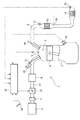
図1は、第1実施形態の構成を示す概略図である。図示されるように、内燃機関たるエンジン1は、シリンダブロック2に形成された燃焼室3の内部で燃料および空気の混合気を燃焼させ、燃焼室3内でピストン4を往復移動させることにより動力を発生する。本実施形態のエンジン1は自動車用多気筒エンジン(1気筒のみ図示)であり、火花点火式内燃機関、より具体的にはガソリンエンジンである。
DESCRIPTION OF EXEMPLARY EMBODIMENTS Hereinafter, preferred embodiments of the invention will be described with reference to the accompanying drawings.
[First Embodiment]
FIG. 1 is a schematic diagram showing the configuration of the first embodiment. As shown in the figure, an
エンジン1のシリンダヘッドには、吸気ポートを開閉する吸気弁Viと、排気ポートを開閉する排気弁Veとが気筒ごとに配設されている。各吸気弁Viおよび各排気弁Veは図示しないカムシャフトによって開閉させられる。また、シリンダヘッドの頂部には、燃焼室3内の混合気に点火するための点火プラグ7が気筒ごとに取り付けられている。
The cylinder head of the
各気筒の吸気ポートは吸気マニホールドを介して吸気集合室であるサージタンク8に接続されている。サージタンク8の上流側には吸気集合通路をなす吸気管13が接続されており、吸気管13の上流端にはエアクリーナ9が設けられている。そして吸気管13には、上流側から順に、エンジンに流入する空気量すなわち吸入空気量を検出するためのエアフローメータ5と、電子制御式スロットルバルブ10とが設けられている。なお吸気ポート、吸気マニホールド、サージタンク8及び吸気管13により吸気通路が形成される。
The intake port of each cylinder is connected to a
吸気通路、特に吸気ポート内に燃料を噴射するインジェクタすなわち燃料噴射弁12が気筒ごとに配設される。インジェクタ12から噴射された燃料は吸入空気と混合されて混合気をなし、この混合気が吸気弁Viの開弁時に燃焼室3に吸入され、ピストン4で圧縮され、点火プラグ7で点火燃焼させられる。
An injector for injecting fuel into an intake passage, particularly an intake port, that is, a
一方、各気筒の排気ポートは、排気マニホールドを介して排気集合通路をなす排気管6に接続されている。これら排気ポート、排気マニホールド及び排気管6により排気通路が形成される。排気管6には、その上流側と下流側に、酸素吸蔵能を有する三元触媒からなる触媒、即ち上流触媒11及び下流触媒19が直列に設けられている。例えば、上流触媒11は排気マニホールドの直後に配置され、下流触媒19は車両の床下などに配置される。
On the other hand, the exhaust port of each cylinder is connected to an
上流触媒11の上流側及び下流側(前後)に、それぞれ、酸素濃度に基づいて排気ガスの空燃比を検出する空燃比センサ、即ち触媒前センサ17及び触媒後センサ18が設けられている。図5に示すように、触媒前センサ17は所謂広域空燃比センサからなり、比較的広範囲に亘る空燃比を連続的に検出可能で、その空燃比に比例した値の信号を出力する。他方、触媒後センサ18は所謂O2センサからなり、理論空燃比を境に出力値が急変する特性(Z特性)を持つ。
An air-fuel ratio sensor that detects the air-fuel ratio of the exhaust gas based on the oxygen concentration, that is, a
また、下流触媒11の下流側(後)に、触媒後センサ18と同様の下流触媒後センサ23が設けられている。
Further, a downstream
上述の点火プラグ7、スロットルバルブ10及びインジェクタ12等は、制御手段としての電子制御ユニット(以下ECUと称す)20に電気的に接続されている。ECU20は、何れも図示されないCPU、ROM、RAM、入出力ポート、および記憶装置等を含むものである。またECU20には、図示されるように、前述のエアフローメータ5、触媒前センサ17、触媒後センサ18、下流触媒後センサ23のほか、エンジン1のクランク角を検出するクランク角センサ14、アクセル開度を検出するアクセル開度センサ15、その他の各種センサが図示されないA/D変換器等を介して電気的に接続されている。ECU20は、各種センサの検出値等に基づいて、所望の出力が得られるように、点火プラグ7、インジェクタ12、スロットルバルブ10等を制御し、点火時期、燃料噴射量、燃料噴射時期、スロットル開度等を制御する。
The spark plug 7, the
上流触媒11及び下流触媒19は、これに流入する排気ガスの空燃比A/Fが理論空燃比(ストイキ、例えばA/Fs=14.6)のときにNOx ,HCおよびCOを同時に高効率で浄化する。よってこの特性に合わせて、ECU20は、エンジンの通常運転時、上流触媒11に流入する排気ガスの空燃比がストイキに一致するよう、燃焼室3に供給される混合気の空燃比(具体的にはインジェクタ12からの燃料噴射量)を触媒前センサ17および触媒後センサ18の出力に基づきフィードバック制御する。
When the air-fuel ratio A / F of the exhaust gas flowing into the
ここで、主に異常診断の対象となる上流触媒11についてより詳細に説明する。なお下流触媒19も上流触媒11と同様に構成されている。図2に示すように、触媒11においては、図示しない担体基材の表面上にコート材31が被覆され、このコート材31に微粒子状の触媒成分32が多数分散配置された状態で担持され、触媒11内部で露出されている。触媒成分32は主にPt,Pd等の貴金属からなり、NOx ,HCおよびCOといった排ガス成分を反応させる際の活性点となる。他方、コート材31は、排気ガスと触媒成分32との界面における反応を促進させる助触媒の役割を担うと共に、雰囲気ガスの空燃比に応じて酸素を吸放出可能な酸素吸蔵成分を含む。酸素吸蔵成分は例えば二酸化セリウムCeO2やジルコニアからなる。なお、「吸蔵」と同義で「吸収」または「吸着」を用いることもある。
Here, the
例えば、触媒内の雰囲気ガスが理論空燃比よりリーンであると、触媒成分32の周囲に存在する酸素吸蔵成分が雰囲気ガスから酸素を吸収し、この結果NOxが還元され、浄化される。他方、触媒内の雰囲気ガスが理論空燃比よりリッチであると、酸素吸蔵成分に吸蔵されていた酸素が放出され、この放出された酸素によりHCおよびCOが酸化され、浄化される。
For example, if the atmospheric gas in the catalyst is leaner than the stoichiometric air-fuel ratio, the oxygen storage component present around the
この酸素吸放出作用により、通常のストイキ空燃比制御に際して実際の空燃比がストイキに対して多少ばらついたとしても、このばらつきを吸収することができる。 Due to this oxygen absorption / release action, even if the actual air-fuel ratio varies somewhat with respect to the stoichiometry during normal stoichiometric air-fuel ratio control, this variation can be absorbed.
ところで、新品状態の触媒11では前述したように多数の触媒成分32が均等に分散配置されており、排気ガスと触媒成分32との接触確率が高い状態に維持されている。しかしながら、触媒11が劣化してくると、一部の触媒成分32に消失が見られるほか、触媒成分32同士が排気熱で焼き固まって焼結状態になるものがある(図の破線参照)。こうなると排気ガスと触媒成分32との接触確率が低下し、浄化率を落としめる原因となる。そしてこのほかに、触媒成分32の周囲に存在するコート材31の量、即ち酸素吸蔵成分の量が減少し、酸素吸蔵能自体が低下する。
Incidentally, in the
このように、触媒11の劣化度と酸素吸蔵能との間には相関関係がある。そこで本実施形態では、特にエミッションへの影響が大きい上流触媒11の酸素吸蔵能を検出することにより、上流触媒11の劣化度を間接的に検出し、上流触媒11が正常か異常かを診断することとしている。ここで触媒11の酸素吸蔵能は、現状の触媒11が吸蔵し得る最大酸素量である酸素吸蔵容量(OSC;O2 Storage Capacity、単位はg)の大きさによって表される。従って酸素吸蔵容量は触媒11の劣化度を表す指標値(劣化指標値)をなす。
Thus, there is a correlation between the degree of deterioration of the
本実施形態の触媒異常診断は前述のCmax法によるものを基本とする。そして異常診断に際しては、ECU20によりアクティブ空燃比制御が実行される。すなわちECU20は、触媒11に供給される排気ガスの空燃比、具体的には燃焼室3内の混合気の空燃比を、中心空燃比であるストイキA/Fsを境にリッチ及びリーンに交互に且つアクティブに切り替える。
The catalyst abnormality diagnosis of the present embodiment is basically based on the Cmax method described above. In the abnormality diagnosis, the active air-fuel ratio control is executed by the
また、アクティブ空燃比制御および診断は、所定の前提条件が満たされているときに限って実行される。この前提条件については後述する。 The active air-fuel ratio control and diagnosis are executed only when predetermined preconditions are satisfied. This precondition will be described later.
本実施形態では、上流触媒11および下流触媒19の両方の酸素吸蔵容量を計測し、これら計測値に基づき両触媒を診断できるようになっている。しかしながらここでは、便宜上、図3及び図4を用いて、上流触媒11のみの酸素吸蔵容量を単独で計測する場合の方法(基本方法という)を説明する。
In this embodiment, the oxygen storage capacity of both the
図3(A)において、破線は目標空燃比A/Ft、実線は触媒前センサ17の出力(但し触媒前空燃比A/Ffへの換算値)を示す。また図3(B)において、実線は触媒後センサ18の出力(但しその出力電圧Vr)を示す。 3A, the broken line indicates the target air-fuel ratio A / Ft, and the solid line indicates the output of the pre-catalyst sensor 17 (however, the converted value to the pre-catalyst air-fuel ratio A / Ff). In FIG. 3B, the solid line indicates the output of the post-catalyst sensor 18 (however, the output voltage Vr).
図示するように、時刻t1より前では、空燃比をリーンに切り替えるリーン制御が実行され、目標空燃比A/Ftはリーン空燃比A/Fl(例えば15.1)とされ、触媒11には、目標空燃比A/Ftと等しい空燃比のリーンガスが供給されている。このとき触媒11は酸素を吸蔵し続けているが、飽和状態即ち満杯まで酸素を吸蔵した時点でそれ以上酸素を吸蔵できなくなる。この結果、リーンガスが触媒11を通り抜けて触媒11の下流側に流れ出す。こうなると触媒後センサ18の出力がリーン側に変化し、出力電圧Vrが所定のリーン判定値VL(例えば0.21V)に達した時点t1で、目標空燃比A/Ftがリッチ空燃比A/Fr(例えば14.1)に切り替えられる。これによりリッチ制御が開始され、目標空燃比A/Ftと等しい空燃比のリッチガスが供給されるようになる。
As shown in the figure, before the time t1, lean control for switching the air-fuel ratio to lean is executed, the target air-fuel ratio A / Ft is set to lean air-fuel ratio A / Fl (for example, 15.1), and the catalyst 11 A lean gas having an air-fuel ratio equal to the target air-fuel ratio A / Ft is supplied. At this time, the
リッチガスが供給されると、触媒11は吸蔵酸素を放出し続ける。やがて触媒11から吸蔵酸素が放出され尽くすとその時点で触媒11は酸素を放出できなくなり、リッチガスが触媒11を通り抜けて触媒11の下流側に流れ出す。こうなると触媒後センサ18の出力がリッチ側に変化し、出力電圧Vrが所定のリッチ判定値VR(例えば0.59V)に達した時点t2で、目標空燃比A/Ftがリーン空燃比A/Fl(例えば15.1)に切り替えられる。これにより再びリーン制御が開始され、目標空燃比A/Ftと等しい空燃比のリーンガスが供給されるようになる。
When the rich gas is supplied, the
再び、触媒11が満杯まで酸素を吸蔵し、触媒後センサ18の出力電圧Vrがリーン判定値VLに達すると、その時点t3で、目標空燃比A/Ftがリッチ空燃比A/Frに切り替えられ、リッチ制御が開始される。
When the
こうして、触媒後センサ18の出力が反転する毎に、リーン制御とリッチ制御とが交互に繰り返し実行される。
In this way, every time the output of the
このアクティブ空燃比制御の実行中、次の方法で触媒11の酸素吸蔵容量OSCが計測される。
During execution of this active air-fuel ratio control, the oxygen storage capacity OSC of the
触媒11の有する酸素吸蔵容量が大きいほど、酸素を吸蔵或いは放出し続けることのできる時間が長くなる。つまり、触媒が劣化していない場合は触媒後センサ出力Vrの反転周期(例えばt1からt2までの時間)が長くなり、触媒の劣化が進むほどその反転周期は短くなる。
The larger the oxygen storage capacity of the
そこで、このことを利用して酸素吸蔵容量OSCが次のようにして計測される。図4に示すように、時刻t1で目標空燃比A/Ftがリッチ空燃比A/Frに切り替えられた直後、僅かに遅れて実際値としての触媒前空燃比A/Ffがリッチ空燃比A/Frに切り替わる。そして触媒前空燃比A/FfがストイキA/Fsに達した時点t11から、次に触媒後センサ出力Vrが反転する時点t2まで、次式(1)により、所定の演算周期毎の酸素吸蔵容量dOSCが逐次的に算出され、且つこの酸素吸蔵容量dOSCが時刻t11から時刻t2まで逐次的に積算される。こうして、リッチ制御時における最終積算値としての酸素吸蔵容量OSC、すなわち図4にOSCbで示す放出酸素量が計測される。 Therefore, using this fact, the oxygen storage capacity OSC is measured as follows. As shown in FIG. 4, immediately after the target air-fuel ratio A / Ft is switched to the rich air-fuel ratio A / Fr at time t1, the pre-catalyst air-fuel ratio A / Ff as an actual value is slightly delayed with the rich air-fuel ratio A / Ff. Switch to Fr. From the time t11 when the pre-catalyst air-fuel ratio A / Ff reaches the stoichiometric A / Fs to the time t2 when the post-catalyst sensor output Vr is next reversed, the oxygen storage capacity for each predetermined calculation cycle is obtained by the following equation (1). dOSC is sequentially calculated, and the oxygen storage capacity dOSC is sequentially accumulated from time t11 to time t2. Thus, the oxygen storage capacity OSC as the final integrated value during the rich control, that is, the amount of released oxygen indicated by OSCb in FIG. 4 is measured.
![]()
![]()
Qは燃料噴射量であり、空燃比差ΔA/Fに燃料噴射量Qを乗じるとストイキに対し不足又は過剰分の空気量を算出できる。σは空気に含まれる酸素割合(約0.23)を表す定数である。 Q is the fuel injection amount. When the air-fuel ratio difference ΔA / F is multiplied by the fuel injection amount Q, the air amount that is insufficient or excessive with respect to the stoichiometry can be calculated. σ is a constant representing the proportion of oxygen contained in air (about 0.23).
リーン制御時にも同様に酸素吸蔵容量、すなわち図4にOSCaで示す吸蔵酸素量が計測される。そしてリッチ制御とリーン制御が交互に行われる度に、放出酸素量と吸蔵酸素量が交互に計測される。 Similarly, during lean control, the oxygen storage capacity, that is, the amount of stored oxygen indicated by OSCa in FIG. 4 is measured. Each time the rich control and the lean control are alternately performed, the released oxygen amount and the stored oxygen amount are alternately measured.
ここで分かるように、「酸素吸蔵容量」とは「放出酸素量」と「吸蔵酸素量」を総称する用語である。また「放出酸素量」とはリッチ制御中に触媒が放出する酸素量をいい、「吸蔵酸素量」とはリーン制御中に触媒が吸蔵する酸素量をいう。 As can be seen here, “oxygen storage capacity” is a generic term for “amount of released oxygen” and “amount of stored oxygen”. The “released oxygen amount” refers to the amount of oxygen released by the catalyst during rich control, and the “occluded oxygen amount” refers to the amount of oxygen stored by the catalyst during lean control.
こうして複数ずつの放出酸素量と吸蔵酸素量との計測値が得られたならば、次の方法により触媒の正異常判定が行われる。 If a plurality of measured values of the released oxygen amount and the occluded oxygen amount are obtained in this way, whether the catalyst is normal or abnormal is determined by the following method.
まずECU20は、これら放出酸素量と吸蔵酸素量との複数の計測値の平均値を算出する。そしてこの平均値を所定の異常判定値α1と比較する。ECU20は、平均値が異常判定値α1より大きいときには上流触媒11を正常と判定し、平均値が異常判定値α1以下のときには上流触媒11を異常と判定する。なお上流触媒11を異常と判定した場合、その事実をユーザに知らせるため、チェックランプ等の警告装置(図示せず)を起動させるのが好ましい。
First, the
ところで前述したように、本実施形態では、上流触媒11および下流触媒19の両方の酸素吸蔵容量を計測し、これら計測値に基づき両触媒を診断できるようになっている。
As described above, in this embodiment, the oxygen storage capacities of both the
この場合、目標空燃比A/Ftの切り替えタイミングが前記基本方法と異なる。例えばリッチ制御中、前記基本方法では、触媒後センサ18の出力がリッチに反転した時(t2)に目標空燃比A/Ftをリーンに切り替えた。しかしながら本実施形態では、このタイミングではなく、下流触媒後センサ23の出力がリッチに反転した時に目標空燃比A/Ftをリーンに切り替える。
In this case, the target air-fuel ratio A / Ft switching timing is different from the basic method. For example, during the rich control, in the basic method, the target air-fuel ratio A / Ft is switched to lean when the output of the
リッチ制御中、上流触媒11から吸蔵酸素が放出され尽くすとリッチガスが上流触媒11から流れ出し、触媒後センサ18の出力がリッチに反転する。そしてこのリッチガスは下流触媒19に供給され、下流触媒19から吸蔵酸素を放出させる。下流触媒19から吸蔵酸素が放出され尽くすとリッチガスが下流触媒19から流れ出し、下流触媒後センサ23の出力がリッチに反転する。この反転と同時にリッチ制御終了となり、目標空燃比A/Ftがリーンに切り替えられる。
If the stored oxygen is exhausted from the
触媒後センサ18の出力がリッチに反転するまでの期間では前記基本方法と同じ要領で上流触媒11の放出酸素量が計測される。また、触媒後センサ18の出力がリッチに反転した時から、下流触媒後センサ23の出力がリッチに反転するまでの期間において、下流触媒19の放出酸素量が計測される。すなわち当該期間中、式(1)に基づく演算周期毎の酸素吸蔵容量dOSCが逐次的に積算される。
In the period until the output of the
リーン制御中にも同様の方法で、上流触媒11と下流触媒19の吸蔵酸素量が計測される。この場合、下流触媒後センサ23の出力がリーンに反転した時にリーン制御終了となり、目標空燃比A/Ftがリッチに切り替えられる。
During the lean control, the stored oxygen amounts of the
下流触媒19の正異常判定の方法は前記基本方法と同様である。すなわち、下流触媒19の放出酸素量と吸蔵酸素量との複数の計測値の平均値を算出し、この平均値を、下流触媒用の別の異常判定値α2と比較する。そして平均値が異常判定値α2より大きいときには下流触媒19を正常と判定し、平均値が異常判定値α2以下のときには下流触媒19を異常と判定する。異常判定時に警告装置を起動させるのが好ましいのも前記同様である。
The method for determining whether the
なお、上流触媒11と下流触媒19の酸素吸蔵容量計測値は必ずしも平均値でなくてもよい。
Note that the measured values of the oxygen storage capacity of the
次に、本実施形態における燃料性状判定、具体的には燃料の硫黄濃度の推定について説明する。ここで、予め使用が予定されている硫黄濃度が低い燃料、即ち硫黄濃度が所定濃度未満の燃料を低S燃料という。また硫黄濃度が高い燃料、即ち硫黄濃度が当該所定濃度以上の燃料を高S燃料という。 Next, the fuel property determination in this embodiment, specifically, estimation of the sulfur concentration of the fuel will be described. Here, a fuel having a low sulfur concentration scheduled to be used in advance, that is, a fuel having a sulfur concentration lower than a predetermined concentration is referred to as a low S fuel. A fuel having a high sulfur concentration, that is, a fuel having a sulfur concentration equal to or higher than the predetermined concentration is referred to as a high S fuel.
一般に、触媒温度が低いほど触媒への硫黄影響は増加する。すなわち、燃料の硫黄濃度が一定であっても、触媒温度が低いほど触媒のS被毒度合いは大きくなり、また触媒の硫黄蓄積量は増加する。 In general, the lower the catalyst temperature, the greater the effect of sulfur on the catalyst. That is, even if the sulfur concentration of the fuel is constant, the lower the catalyst temperature, the greater the degree of S poisoning of the catalyst, and the amount of sulfur accumulation in the catalyst increases.
また、上流触媒11と下流触媒19を比較した場合、下流触媒19の方がより低温の排気ガスが供給されるので、より低温となる傾向がある。
Further, when the
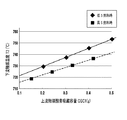
従って、燃料の硫黄濃度が一定の場合、上流触媒11の酸素吸蔵容量と下流触媒19の酸素吸蔵容量との間には一定の相関関係がある。これを図示したのが図6である。
Therefore, when the sulfur concentration of the fuel is constant, there is a certain correlation between the oxygen storage capacity of the
図6において、菱形および実線は低S燃料使用時のデータであり、四角および破線は高S燃料使用時のデータである。まず、燃料の硫黄濃度に拘わらず、下流触媒19の酸素吸蔵容量OSC2は常に上流触媒11の酸素吸蔵容量OSC1よりも小さい。その理由は下流触媒19が上流触媒11より低温だからである。そして燃料の硫黄濃度が一定の場合、すなわち低S燃料使用時と高S燃料使用時のいずれにおいても、下流触媒19の酸素吸蔵容量OSC2は上流触媒11の酸素吸蔵容量OSC1に対し比例関係にある。その理由は上流触媒11と下流触媒19の劣化が同程度に進むからである。
In FIG. 6, diamonds and solid lines are data when low S fuel is used, and squares and broken lines are data when high S fuel is used. First, regardless of the sulfur concentration of the fuel, the oxygen storage capacity OSC2 of the
さらに、上流触媒11の酸素吸蔵容量OSC1が一定の場合、高S燃料使用時の下流触媒19の酸素吸蔵容量OSC2は低S燃料使用時の下流触媒19の酸素吸蔵容量OSC2よりも小さい。その理由は、上流触媒11と比較してより低温な下流触媒19の方が、相対的に高S燃料の硫黄影響を強く受け、S被毒度合いが大きくなるからである。
Further, when the oxygen storage capacity OSC1 of the
そこで本実施形態では、この特性を利用して燃料の硫黄濃度をECU20により推定する。すなわち、図6に示す如き低S燃料使用時の上流触媒11の酸素吸蔵容量OSC1と下流触媒19の酸素吸蔵容量OSC2との関係を予めマップ(関数でもよい。以下同様)の形でECU20に記憶しておく。図7には図6のデータを反映したより具体的なマップを示す。そして、実際に計測された上流触媒11の酸素吸蔵容量(計測上流酸素吸蔵容量という)OSC1aに対応した下流触媒19の酸素吸蔵容量OSC2を、当該マップから推定する。この推定された酸素吸蔵容量(推定下流酸素吸蔵容量という)OSC2eは、図6の実線上の値となる。次いで推定下流酸素吸蔵容量OSC2eと、実際に計測された下流触媒19の酸素吸蔵容量(計測下流酸素吸蔵容量という)OSC2aとに基づき、使用燃料の硫黄濃度を推定する。
Therefore, in this embodiment, the
具体的には、推定下流酸素吸蔵容量OSC2eと計測下流酸素吸蔵容量OSC2aの差ΔOSC2=|OSC2e−OSC2a|が所定のしきい値β1以上のとき、使用燃料の硫黄濃度が所定濃度以上である、すなわち使用燃料が高S燃料であると推定する。他方、差ΔOSC2が所定のしきい値β1未満のときには、使用燃料の硫黄濃度が所定濃度未満である、すなわち使用燃料が低S燃料であると推定する。 Specifically, when the difference ΔOSC2 = | OSC2e−OSC2a | between the estimated downstream oxygen storage capacity OSC2e and the measured downstream oxygen storage capacity OSC2a is equal to or greater than a predetermined threshold value β1, the sulfur concentration of the fuel used is equal to or greater than the predetermined concentration. That is, it is estimated that the fuel used is high S fuel. On the other hand, when the difference ΔOSC2 is less than the predetermined threshold value β1, it is estimated that the sulfur concentration of the fuel used is less than the predetermined concentration, that is, the fuel used is low S fuel.
低S燃料使用時であれば、低S燃料を前提とした推定下流酸素吸蔵容量OSC2eと計測下流酸素吸蔵容量OSC2aの差ΔOSC2が小さい筈なので、この場合には使用燃料を低S燃料と推定できる。しかしながら、高S燃料使用時であれば、低S燃料を前提とした推定下流酸素吸蔵容量OSC2eと計測下流酸素吸蔵容量OSC2aの差ΔOSC2が大きくなる。よってこの場合には使用燃料を高S燃料と推定する。 If the low S fuel is used, the difference ΔOSC2 between the estimated downstream oxygen storage capacity OSC2e and the measured downstream oxygen storage capacity OSC2a on the premise of the low S fuel should be small. In this case, the used fuel can be estimated as the low S fuel. . However, when the high S fuel is used, the difference ΔOSC2 between the estimated downstream oxygen storage capacity OSC2e and the measured downstream oxygen storage capacity OSC2a on the premise of the low S fuel becomes large. Therefore, in this case, the fuel used is estimated to be high S fuel.
この推定方法には次の利点がある。まず、比較的高価な硫黄濃度センサを新たに設置する必要がないので装置全体を比較的低廉に抑えられるという利点がある。 This estimation method has the following advantages. First, since it is not necessary to newly install a relatively expensive sulfur concentration sensor, there is an advantage that the entire apparatus can be suppressed relatively inexpensively.
次に、上流触媒11および下流触媒19の一方のみの酸素吸蔵容量低下量に基づき燃料の硫黄濃度を推定することが考えられるが、これだと、触媒劣化に起因する低下なのか、あるいは硫黄影響に起因する低下なのかを区別することができない。しかし、本実施形態の推定方法によれば、上流触媒11および下流触媒19の両方の酸素吸蔵容量計測値ないし情報を利用する。よって触媒劣化原因を排除し、硫黄影響原因のみに基づいて硫黄濃度を推定できる。従って好適でしかも高精度な方法により燃料の硫黄濃度を推定することが可能である。
Next, it is conceivable that the sulfur concentration of the fuel is estimated based on the oxygen storage capacity reduction amount of only one of the
ここで好ましくは、ECU20は、差ΔOSC2の比較対象であるしきい値β1を、計測上流酸素吸蔵容量OSC1aに応じて可変設定する。具体的には、計測上流酸素吸蔵容量OSC1aの値が大きいほど、しきい値β1を大きな値に設定する。この設定は予め定めたマップを利用して行うことができる。
Here, preferably, the
図6から理解されるように、推定下流酸素吸蔵容量OSC2eと計測下流酸素吸蔵容量OSC2aの差ΔOSC2は、高S燃料使用時においては、計測上流酸素吸蔵容量OSC1aが大きくなるほど大きくなる傾向がある。よってこの傾向に合わせて、計測上流酸素吸蔵容量OSC1aの値が大きいほど、しきい値β1を大きくすることにより、図6の特性をより反映し、推定精度を一層向上することが可能となる。 As understood from FIG. 6, the difference ΔOSC2 between the estimated downstream oxygen storage capacity OSC2e and the measured downstream oxygen storage capacity OSC2a tends to increase as the measured upstream oxygen storage capacity OSC1a increases when the high S fuel is used. Therefore, in accordance with this tendency, the larger the value of the measured upstream oxygen storage capacity OSC1a, the larger the threshold value β1, thereby more reflecting the characteristics shown in FIG. 6 and further improving the estimation accuracy.
なお、ここでの例では硫黄濃度を高低の二段階で推定したが、差ΔOSC2に応じて硫黄濃度を無段階で推定してもよい。また差ΔOSC2に代わって、推定下流酸素吸蔵容量OSC2eと計測下流酸素吸蔵容量OSC2aの比R=OSC2e/OSC2aを用いてもよい。この場合比Rが大きいほど高い硫黄濃度を推定することになる。 In this example, the sulfur concentration is estimated in two steps of high and low, but the sulfur concentration may be estimated in a stepless manner according to the difference ΔOSC2. Instead of the difference ΔOSC2, the ratio R = OSC2e / OSC2a of the estimated downstream oxygen storage capacity OSC2e and the measured downstream oxygen storage capacity OSC2a may be used. In this case, the higher the ratio R, the higher the sulfur concentration is estimated.
ところで、使用燃料が高S燃料であることを推定した場合、硫黄影響を考慮して触媒の異常診断を実施するのが好ましい。そこで以下にはそのような異常診断の好適例を示す。 By the way, when it is estimated that the fuel to be used is a high S fuel, it is preferable to perform abnormality diagnosis of the catalyst in consideration of the influence of sulfur. Therefore, a suitable example of such an abnormality diagnosis will be shown below.
図8に異常診断処理のルーチンを示す。このルーチンはECU20により所定の演算周期(例えば16msec)毎に繰り返し実行される。
FIG. 8 shows a routine for abnormality diagnosis processing. This routine is repeatedly executed by the
まずステップS101において、診断に適した前提条件が成立しているか否かが判断される。例えば、(1)エンジンが暖機状態にあり、(2)上流触媒11および下流触媒19が暖機状態にあり、(3)触媒前センサ17、触媒後センサ18および下流触媒後センサ23が活性状態にあり、(4)エンジンが定常運転状態にある場合に、前提条件が成立する。
First, in step S101, it is determined whether a precondition suitable for diagnosis is satisfied. For example, (1) the engine is warmed up, (2) the
条件(1)の成否は図示しない水温センサの検出値に基づき判断され、例えば当該検出値が75℃以上だと条件成立となる。条件(2)の成否は別途推定または検出される各触媒の温度に基づき判断される。条件(3)の成否は各センサの素子インピーダンスに基づく素子温度の検出値に基づき判断される。条件(4)の成否は、例えば吸入空気量Ga及びエンジン回転速度Neの所定期間内における変動幅が所定範囲内に収まっているか否かによって判断される。なお吸入空気量Gaはエアフローメータ5により検出され、エンジン回転速度Neはクランク角センサ14の出力から計算される。なお前提条件についてはこれ以外の例も可能である。
The success or failure of the condition (1) is determined based on a detection value of a water temperature sensor (not shown). For example, if the detection value is 75 ° C. or higher, the condition is satisfied. The success or failure of the condition (2) is determined based on the temperature of each catalyst estimated or detected separately. The success or failure of the condition (3) is determined based on the detected value of the element temperature based on the element impedance of each sensor. The success or failure of the condition (4) is determined, for example, by whether or not the fluctuation range of the intake air amount Ga and the engine speed Ne within a predetermined period is within a predetermined range. The intake air amount Ga is detected by the
前提条件が成立していない場合には処理が終了され、他方、前提条件が成立している場合にはステップS102に進む。 If the precondition is not satisfied, the process is terminated. On the other hand, if the precondition is satisfied, the process proceeds to step S102.
ステップS102では、アクティブ空燃比制御が実行される。そしてステップS103では、アクティブ空燃比制御の実行中に、上流触媒11の酸素吸蔵容量OSC1と下流触媒19の酸素吸蔵容量OSC2とが計測される。
In step S102, active air-fuel ratio control is executed. In step S103, the oxygen storage capacity OSC1 of the
次いでステップS104では、上流触媒11の酸素吸蔵容量OSC1と下流触媒19の酸素吸蔵容量OSC2との計測が完了したか否かが判断される。複数である所定数ずつの酸素吸蔵容量OSC1,OSC2のデータが取得されたとき判断結果はイエスとなり、そうでなければ判断結果はノーとなり、処理が終了される。
Next, in step S104, it is determined whether or not the measurement of the oxygen storage capacity OSC1 of the
判断結果がイエスのとき、ステップS105に進んで、推定下流酸素吸蔵容量OSC2eと計測下流酸素吸蔵容量OSC2aの差ΔOSC2=|OSC2e−OSC2a|が算出される。 When the determination result is yes, the process proceeds to step S105, and a difference ΔOSC2 = | OSC2e−OSC2a | between the estimated downstream oxygen storage capacity OSC2e and the measured downstream oxygen storage capacity OSC2a is calculated.
このステップではまず、それぞれ計測された上流触媒11と下流触媒19の酸素吸蔵容量OSC1,OSC2の平均値が求められ、これらが最終的な計測値すなわち計測上流酸素吸蔵容量OSC1aおよび計測下流酸素吸蔵容量OSC2aとされる。
In this step, first, the average values of the oxygen storage capacities OSC1 and OSC2 of the measured
そして、図6および図7に示したようなマップから、計測上流酸素吸蔵容量OSC1aに対応した推定下流酸素吸蔵容量OSC2eが算出される。 Then, the estimated downstream oxygen storage capacity OSC2e corresponding to the measured upstream oxygen storage capacity OSC1a is calculated from the maps as shown in FIGS.
さらに式:ΔOSC2=|OSC2e−OSC2a|に従い、差ΔOSC2が算出される。この差ΔOSC2が、使用燃料が高S燃料であるか否かを判定するための高S燃料判定指標値となる。 Further, the difference ΔOSC2 is calculated according to the equation: ΔOSC2 = | OSC2e−OSC2a |. This difference ΔOSC2 becomes a high S fuel determination index value for determining whether or not the fuel used is high S fuel.
次に、ステップS106において、差ΔOSC2がしきい値β1と比較される。 Next, in step S106, the difference ΔOSC2 is compared with the threshold value β1.
差ΔOSC2がしきい値β1未満のときには、使用燃料が低S燃料であると推定され、通常通り、ステップS109において正常・異常判定が実行される。すなわち、計測上流酸素吸蔵容量OSC1aおよび計測下流酸素吸蔵容量OSC2aがそれぞれ異常判定値α1およびα2と比較され、上流触媒11および下流触媒19が正常か異常かが判定される。これにより処理が終了される。
When the difference ΔOSC2 is less than the threshold value β1, it is estimated that the fuel used is low S fuel, and normal / abnormal determination is executed in step S109 as usual. That is, the measured upstream oxygen storage capacity OSC1a and the measured downstream oxygen storage capacity OSC2a are compared with the abnormality determination values α1 and α2, respectively, to determine whether the
他方、差ΔOSC2がしきい値β1以上のときには、使用燃料が高S燃料であると推定される。この場合、ステップS107に進んで、今回計測された計測上流酸素吸蔵容量OSC1aおよび計測下流酸素吸蔵容量OSC2aに基づく正常・異常判定が保留される。上流触媒11および下流触媒19がS被毒しており、誤診断する可能性があるからである。またこのステップS107では計測値データを破棄するなどの所定のクリア処理が行われる。
On the other hand, when the difference ΔOSC2 is equal to or greater than the threshold value β1, it is estimated that the fuel used is high S fuel. In this case, the process proceeds to step S107, and normality / abnormality determination based on the measured upstream oxygen storage capacity OSC1a and the measured downstream oxygen storage capacity OSC2a measured this time is put on hold. This is because the
次いでステップS108において、ステップS101の前提条件のうちの触媒温度条件、すなわち前記条件(2)が、より高温側に変更される。すなわち前記条件(2)が、上流触媒温度が所定の第1温度Ts1以上且つ下流触媒温度が所定の第2温度Ts2以上であるとすると、触媒温度条件の変更後には、変更前の第1温度Ts1および第2温度Ts2がより高温側の値Ts1’およびTs2’に変更される。これら変更後の値Ts1’およびTs2’は、上流触媒11および下流触媒19のS被毒が解消するような十分高温な値であるのが好ましい。こうして触媒温度条件が変更されたら処理が終了される。
Next, in step S108, the catalyst temperature condition among the preconditions in step S101, that is, the condition (2) is changed to a higher temperature side. That is, if the condition (2) is that the upstream catalyst temperature is equal to or higher than the predetermined first temperature Ts1 and the downstream catalyst temperature is equal to or higher than the predetermined second temperature Ts2, the first temperature before the change is changed after the change in the catalyst temperature condition. Ts1 and the second temperature Ts2 are changed to higher temperature values Ts1 ′ and Ts2 ′. These changed values Ts1 'and Ts2' are preferably high enough to eliminate S poisoning of the
次回以降の再診断は、本ルーチンに従い、より高温な触媒温度条件が成立した場合に限って実行される。すなわち、ステップS101の前提条件成立時に上流触媒11と下流触媒19の酸素吸蔵容量OSC1,OSC2が計測され、これら計測値に基づき差ΔOSC2が算出される。このとき上流触媒11および下流触媒19の硫黄影響すなわちS被毒は解消している可能性が高い。よってこの場合には差ΔOSC2がしきい値β1未満となり、通常通り正常・異常判定が実行される。こうして、変更された触媒温度条件下で、計測された酸素吸蔵容量OSC1,OSC2に基づき、上流触媒11および下流触媒19が正常か異常かが診断される。
The re-diagnosis after the next time is executed only when a higher-temperature catalyst temperature condition is satisfied according to this routine. That is, the oxygen storage capacities OSC1 and OSC2 of the
上記診断処理によれば、使用燃料が高S燃料であると推定された場合、正常・異常判定が保留され、診断は実質的に禁止される。よって、上流触媒11および下流触媒19がS被毒した状態で診断を行うことを禁止し、誤診断を未然に防止することができる。特に、本来異常でない触媒を誤って異常と診断してしまうことを防止できる。なお、低S燃料使用時には通常通り診断を行うことができるので、診断頻度確保との両立も図れる。
According to the above diagnosis processing, when it is estimated that the fuel used is high S fuel, the normality / abnormality determination is suspended and the diagnosis is substantially prohibited. Therefore, it is possible to prohibit the diagnosis in a state where the
また、この場合により高温な触媒温度条件下で再度診断を実行するので、上流触媒11および下流触媒19の硫黄影響を除去した上で診断を実行でき、誤診断の防止と診断頻度確保とが図れる。
In this case, since the diagnosis is executed again under a higher temperature condition of the catalyst, the diagnosis can be executed after removing the influence of the sulfur of the
なお、上記異常診断処理においては正常・異常判定が保留ないし禁止された場合に触媒温度条件を変更した。しかしながら、これらは独立して一方のみ行うことが可能である。 In the abnormality diagnosis process, the catalyst temperature condition was changed when normality / abnormality determination was suspended or prohibited. However, these can be done independently only one way.
また、上記異常診断処理においては上流触媒11と下流触媒19の両方を診断した。しかしながら、これらのうちいずれか一方のみを診断するようにしてもよい。すなわち硫黄濃度推定に際しては両方の酸素吸蔵容量OSC1,OSC2を計測するが、触媒異常診断はこれらのうちの一方の計測値のみを用いて一方の触媒についてのみ実行することができる。
In the abnormality diagnosis process, both the
[第2実施形態]
次に、本発明の第2実施形態を説明する。なお前記第1実施形態と同様の部分については説明を省略し、以下相違点を中心に説明する。
[Second Embodiment]
Next, a second embodiment of the present invention will be described. The description of the same parts as in the first embodiment will be omitted, and the differences will be mainly described below.
本実施形態の主な相違点は、上流触媒11及び下流触媒19の劣化指標値として、酸素吸蔵容量の代わりに、触媒温度、特にエンジンの冷間始動時から所定時間経過時点における触媒温度を用いる点である。
The main difference between the present embodiment is that, instead of the oxygen storage capacity, the catalyst temperature, in particular, the catalyst temperature at the time when a predetermined time has elapsed from the cold start of the engine is used as the deterioration index value of the
図9には本実施形態のエンジン1の構成を示す。図示されるように、上流触媒11及び下流触媒19には、これらの温度をそれぞれ計測ないし検出するための上流温度センサ21および下流温度センサ22が設けられている。これら上流温度センサ21および下流温度センサ22はECU20に図示されないA/D変換器等を介して電気的に接続されている。第1実施形態において設けられていた下流触媒後センサ23は省略されている。ECU20は、エンジンが冷間始動された時から所定時間経過した時点における上流触媒11及び下流触媒19の温度を上流温度センサ21および下流温度センサ22により検出する。
FIG. 9 shows the configuration of the
ECU20は、図示しない水温センサの検出値が常温程度の所定範囲内にあるときにエンジンが始動された場合、エンジンが冷間始動されたと判断する。そしてこの冷間始動時から吸入空気量または燃料噴射量を逐次的に積算し、積算値が所定値に達した時に所定時間が経過したと判断する。所定時間は任意に定め得るが、例えば、正常な触媒が未活性から活性に変化するタイミングでの時間(第1の時間)としてもよいし、正常な触媒が活性化した後、暖機状態となってから、診断が行われるタイミングでの時間(第2の時間)としてもよい。
The
触媒の劣化度が大きいほど、触媒反応が緩慢になるので、所定時間経過時点における触媒温度は低くなる。このように触媒の劣化度と触媒温度との間には相関関係がある。そこで本実施形態では、所定時間経過時点における上流触媒11及び下流触媒19の触媒温度を計測ないし検出することにより、各触媒の劣化度を間接的に検出し、各触媒が正常か異常かを診断する。
The greater the degree of deterioration of the catalyst, the slower the catalytic reaction, and the lower the catalyst temperature at the predetermined time point. Thus, there is a correlation between the degree of deterioration of the catalyst and the catalyst temperature. Therefore, in this embodiment, the degree of deterioration of each catalyst is indirectly detected by measuring or detecting the catalyst temperatures of the
第1の時間を採用する場合、この第1の時間が経過した時点における上流触媒11及び下流触媒19の触媒温度が、それぞれ所定の異常判定値と比較される。触媒温度が異常判定値より大きい場合、触媒は正常と判定され、触媒温度上昇量が異常判定値以下の場合、触媒は異常と判定される。
When the first time is employed, the catalyst temperatures of the
第2の時間を採用する場合、この第2の時間が経過した時点における上流触媒11及び下流触媒19の触媒温度が、それぞれ所定の異常判定値と比較される。異常判定値は、積算吸入空気量または積算燃料噴射量に基づき、所定のマップから算出される。そして触媒温度が異常判定値より大きい場合、触媒は正常と判定され、触媒温度が異常判定値以下の場合、触媒は異常と判定される。
When the second time is adopted, the catalyst temperatures of the
次に、本実施形態における燃料性状判定、具体的には燃料の硫黄濃度の推定について説明する。前述したように、下流触媒19の方が上流触媒11より低温となる傾向がある。また触媒温度が低いほど触媒への硫黄影響は増加し、触媒のS被毒度合いは大きくなり、触媒の硫黄蓄積量は増加する。
Next, the fuel property determination in this embodiment, specifically, estimation of the sulfur concentration of the fuel will be described. As described above, the
よって燃料の硫黄濃度が一定の場合、上流触媒11の温度と下流触媒19の温度との間には一定の相関関係がある。これを図示したのが図10である。
Therefore, when the sulfur concentration of the fuel is constant, there is a certain correlation between the temperature of the
図10において、菱形および実線は低S燃料使用時のデータであり、四角および破線は高S燃料使用時のデータである。ここでは第2の時間を採用した場合、すなわち各触媒が活性化した後の暖機状態での値を示す。 In FIG. 10, diamonds and solid lines are data when low S fuel is used, and squares and broken lines are data when high S fuel is used. Here, the values in the warm-up state when the second time is adopted, that is, after each catalyst is activated, are shown.
まず燃料の硫黄濃度に拘わらず、下流触媒温度T2は常に上流触媒温度T1よりも低い。そして燃料の硫黄濃度が一定の場合、すなわち低S燃料使用時と高S燃料使用時のいずれにおいても、下流触媒温度T2は上流触媒温度T1に対し比例関係にある。 First, regardless of the sulfur concentration of the fuel, the downstream catalyst temperature T2 is always lower than the upstream catalyst temperature T1. When the fuel sulfur concentration is constant, that is, when the low S fuel is used and when the high S fuel is used, the downstream catalyst temperature T2 is proportional to the upstream catalyst temperature T1.
さらに、上流触媒温度T1が一定の場合、高S燃料使用時の下流触媒温度T2は低S燃料使用時の下流触媒温度T2よりも低い。その理由は、上流触媒11よりも低温な下流触媒19において、高S燃料による硫黄影響が大きくなり、S被毒度合いが大きくなり、触媒の反応熱が少なくなるからである。
Further, when the upstream catalyst temperature T1 is constant, the downstream catalyst temperature T2 when the high S fuel is used is lower than the downstream catalyst temperature T2 when the low S fuel is used. The reason is that in the
そこで本実施形態では、この特性を利用して燃料の硫黄濃度をECU20により推定する。すなわち、図示の如き低S燃料使用時の上流触媒温度と下流触媒温度の関係を予めマップの形でECU20に記憶しておく。そして、上流温度センサ21によって検出された実際の上流触媒温度(検出上流触媒温度という)T1aに対応した下流触媒温度を、当該マップから推定する。この推定された下流触媒温度(推定下流触媒温度という)T2eは、図10の実線上の値となる。次いで推定下流触媒温度T2eと、下流温度センサ22によって検出された実際の下流触媒温度(検出下流触媒温度という)T2aとに基づき、使用燃料の硫黄濃度を推定する。
Therefore, in this embodiment, the
具体的には、第2の時間経過時点における推定下流触媒温度T2eと検出下流触媒温度T2aの差ΔT2=|T2e−T2a|が所定のしきい値β2以上のとき、使用燃料の硫黄濃度が所定濃度以上である、すなわち使用燃料が高S燃料であると推定する。他方、差ΔT2がしきい値β2未満のときには、使用燃料の硫黄濃度が所定濃度未満である、すなわち使用燃料が低S燃料であると推定する。 Specifically, when the difference ΔT2 = | T2e−T2a | between the estimated downstream catalyst temperature T2e and the detected downstream catalyst temperature T2a when the second time has elapsed is equal to or greater than a predetermined threshold value β2, the sulfur concentration of the fuel used is predetermined. It is estimated that the concentration is higher than the concentration, that is, the fuel used is a high S fuel. On the other hand, when the difference ΔT2 is less than the threshold value β2, it is estimated that the sulfur concentration of the fuel used is less than a predetermined concentration, that is, the fuel used is a low S fuel.
この推定方法にも第1実施形態と同様の利点がある。 This estimation method has the same advantages as the first embodiment.
好ましくは、ECU20は、差ΔT2の比較対象であるしきい値β2を、検出上流触媒温度T1aに応じて可変設定する。具体的には、検出上流触媒温度T1aが高いほどしきい値β2を大きな値に設定する。この設定は予め定めたマップを利用して行うことができる。
Preferably,
図10から理解されるように、推定下流触媒温度T2eと検出下流触媒温度T2aとの差ΔT2は、高S燃料使用時においては、上流触媒温度T1が高くなるほど大きくなる傾向がある。よってこの傾向に合わせて、検出上流触媒温度T1aが高いほどしきい値を大きくすることにより、図10の特性をより反映し、推定精度を一層向上することが可能となる。 As understood from FIG. 10, the difference ΔT2 between the estimated downstream catalyst temperature T2e and the detected downstream catalyst temperature T2a tends to increase as the upstream catalyst temperature T1 increases when the high S fuel is used. Therefore, in accordance with this tendency, the threshold value is increased as the detected upstream catalyst temperature T1a is higher, so that the characteristics shown in FIG. 10 can be reflected more and the estimation accuracy can be further improved.
なお、硫黄濃度を無段階で推定してもよい点、差ΔT2に代わって比R=T2e/T2aを用いてもよい点は前記同様である。 Note that the sulfur concentration may be estimated steplessly, and the ratio R = T2e / T2a may be used instead of the difference ΔT2.
図11に本実施形態に係る異常診断処理のルーチンを示す。このルーチンはECU20により所定の演算周期(例えば16msec)毎に繰り返し実行される。
FIG. 11 shows a routine of abnormality diagnosis processing according to the present embodiment. This routine is repeatedly executed by the
ステップS201は前記ステップS101と同様である。ステップS202では、上流触媒11及び下流触媒19の触媒温度T1,T2がそれぞれ検出される。
Step S201 is the same as step S101. In step S202, the catalyst temperatures T1 and T2 of the
ステップS203では、推定下流触媒温度T2eと検出下流触媒温度T2aとの差ΔT2が算出される。まず図10に示したようなマップから検出上流触媒温度T1aに対応した推定下流触媒温度T2eが算出される。次いで式:ΔT2=|T2e−T2a|に従い、差ΔT2が算出される。この差ΔT2が、使用燃料が高S燃料であるか否かを判定するための高S燃料判定指標値となる。 In step S203, a difference ΔT2 between the estimated downstream catalyst temperature T2e and the detected downstream catalyst temperature T2a is calculated. First, the estimated downstream catalyst temperature T2e corresponding to the detected upstream catalyst temperature T1a is calculated from the map as shown in FIG. Next, the difference ΔT2 is calculated according to the equation: ΔT2 = | T2e−T2a |. This difference ΔT2 becomes a high S fuel determination index value for determining whether or not the fuel used is high S fuel.
次に、ステップS204において、差ΔT2がしきい値β2と比較される。 Next, in step S204, the difference ΔT2 is compared with the threshold value β2.
差ΔT2がしきい値β2未満のときには、使用燃料が低S燃料であると推定され、通常通り、ステップS207において検出上流触媒温度T1aおよび検出下流触媒温度T2aに基づく上流触媒11および下流触媒19の正常・異常判定が実行される。
When the difference ΔT2 is less than the threshold value β2, it is estimated that the fuel to be used is low S fuel. As usual, in step S207, the
他方、差ΔT2がしきい値β2以上のときには、使用燃料が高S燃料であると推定され、前記実施形態同様、ステップS205において正常・異常判定が保留され、ステップS206において触媒温度条件がより高温側に変更される。 On the other hand, when the difference ΔT2 is greater than or equal to the threshold value β2, it is estimated that the fuel used is high S fuel, and the normal / abnormal determination is suspended in step S205 and the catalyst temperature condition is higher in step S206 as in the above embodiment. Is changed to the side.
[第3実施形態]
次に、本発明の第3実施形態を説明する。なお前記実施形態と同様の部分については説明を省略し、以下相違点を中心に説明する。
[Third Embodiment]
Next, a third embodiment of the present invention will be described. The description of the same parts as in the above embodiment will be omitted, and the differences will be mainly described below.
本実施形態の主な相違点は、上流触媒の劣化度を表す劣化指標値に基づき下流触媒の温度を推定し、この下流触媒の推定温度と、別途検出された下流触媒の検出温度とに基づき、使用燃料の硫黄濃度を推定する点にある。 The main difference between the present embodiment is that the temperature of the downstream catalyst is estimated based on the deterioration index value representing the degree of deterioration of the upstream catalyst, and based on the estimated temperature of the downstream catalyst and the detected temperature of the downstream catalyst separately detected. The point is to estimate the sulfur concentration of the fuel used.
図12には本実施形態のエンジン1の構成を示す。図示されるように、下流触媒19には、その温度を検出するための温度検出手段たる下流温度センサ22が設けられている。下流温度センサ22はECU20に図示されないA/D変換器等を介して電気的に接続されている。第1実施形態において設けられていた下流触媒後センサ23と、第2実施形態において設けられていた上流温度センサ21とは省略されている。
FIG. 12 shows the configuration of the
そして第1実施形態またはその基本方法と同様の方法で、上流触媒11の劣化度を表す劣化指標値たる酸素吸蔵容量OSC1が計測される。なお併せて下流触媒19の酸素吸蔵容量OSC2を計測してもよい。
And oxygen storage capacity OSC1 which is a degradation index value showing the degradation degree of the
この計測された上流触媒11の酸素吸蔵容量OSC1、すなわち計測上流酸素吸蔵容量OSC1aに基づき、下流触媒19の温度が推定される。
Based on the measured oxygen storage capacity OSC1 of the
前述したように、下流触媒19の方が上流触媒11より低温となる傾向がある。また触媒温度が低いほど触媒への硫黄影響は増加する。さらに上流触媒11の劣化度が定まると、同程度に劣化した下流触媒19の温度が自ずと定まる。
As described above, the
よって燃料の硫黄濃度が一定の場合、上流触媒11の酸素吸蔵容量OSC1と下流触媒19の温度との間には一定の相関関係がある。これを図示したのが図13である。
Therefore, when the sulfur concentration of the fuel is constant, there is a certain correlation between the oxygen storage capacity OSC1 of the
図13に示すように、燃料の硫黄濃度に拘わらず、下流触媒温度T2は上流触媒の酸素吸蔵容量OSC1と比例関係にある。そして上流触媒の酸素吸蔵容量OSC1が一定の場合、高S燃料使用時の下流触媒温度T2は低S燃料使用時の下流触媒温度T2よりも低い。その理由は、上流触媒11よりも低温な下流触媒19において、高S燃料による硫黄影響が相対的に大きくなり、触媒の反応熱が少なくなるからである。
As shown in FIG. 13, the downstream catalyst temperature T2 is proportional to the oxygen storage capacity OSC1 of the upstream catalyst, regardless of the sulfur concentration of the fuel. When the oxygen storage capacity OSC1 of the upstream catalyst is constant, the downstream catalyst temperature T2 when the high S fuel is used is lower than the downstream catalyst temperature T2 when the low S fuel is used. The reason is that in the
そこで本実施形態では、この特性を利用して燃料の硫黄濃度をECU20により推定する。すなわち、図13に示す如き低S燃料使用時の上流触媒11の酸素吸蔵容量OSC1と下流触媒温度T2の関係を予めマップの形でECU20に記憶しておく。図14には図13のデータを反映したより具体的なマップを示す。そして、実際に計測された上流触媒11の酸素吸蔵容量OSC1すなわち計測上流酸素吸蔵容量OSC1aに対応した下流触媒温度T2を、当該マップから推定する。この推定された下流触媒の温度すなわち推定下流触媒温度T2eは、図13の実線上の値となる。次いで推定下流触媒温度T2eと、下流温度センサ22によって検出された下流触媒温度すなわち検出下流触媒温度T2aとに基づき、使用燃料の硫黄濃度を推定する。
Therefore, in this embodiment, the
具体的には、推定下流触媒温度T2eと検出下流触媒温度T2aの差ΔT2=|T2e−T2a|が所定のしきい値β3以上のとき、使用燃料が高S燃料であると推定する。他方、差ΔT2がしきい値β3未満のとき、使用燃料が低S燃料であると推定する。 Specifically, when the difference ΔT2 = | T2e−T2a | between the estimated downstream catalyst temperature T2e and the detected downstream catalyst temperature T2a is equal to or greater than a predetermined threshold value β3, it is estimated that the used fuel is high S fuel. On the other hand, when the difference ΔT2 is less than the threshold value β3, it is estimated that the used fuel is low S fuel.
この推定方法にも第1および第2実施形態と同様の利点がある。 This estimation method has the same advantages as those of the first and second embodiments.
ここで好ましくは、ECU20は、しきい値β3を、計測上流酸素吸蔵容量OSC1aの値に応じて可変設定する。具体的には、計測上流酸素吸蔵容量OSC1aの値が大きいほどしきい値β3を大きな値に設定する。この設定は予め定めたマップを利用して行うことができる。
Here, preferably, the
図13から理解されるように、推定下流触媒温度T2eと検出下流触媒温度T2aとの差ΔT2は、高S燃料使用時においては、計測上流酸素吸蔵容量OSC1aの値が高くなるほど大きくなる傾向がある。よってこの傾向に合わせて、計測上流酸素吸蔵容量OSC1aの値が大きいほど、しきい値β3を大きくすることにより、図13の特性をより反映し、推定精度を一層向上することが可能となる。 As understood from FIG. 13, the difference ΔT2 between the estimated downstream catalyst temperature T2e and the detected downstream catalyst temperature T2a tends to increase as the measured upstream oxygen storage capacity OSC1a increases when the high S fuel is used. . Therefore, in accordance with this tendency, as the value of the measured upstream oxygen storage capacity OSC1a is larger, the threshold value β3 is increased, thereby more reflecting the characteristics of FIG. 13 and further improving the estimation accuracy.
なお、硫黄濃度を無段階で推定してもよい点、差ΔT2に代わって比R=T2e/T2aを用いてもよい点は前記同様である。 Note that the sulfur concentration may be estimated steplessly, and the ratio R = T2e / T2a may be used instead of the difference ΔT2.
図15に本実施形態に係る異常診断処理のルーチンを示す。このルーチンはECU20により所定の演算周期(例えば16msec)毎に繰り返し実行される。
FIG. 15 shows a routine for abnormality diagnosis processing according to the present embodiment. This routine is repeatedly executed by the
ステップS301,S302は前記ステップS101,S102と同様である。ステップS303では、アクティブ空燃比制御実行中に上流触媒11の酸素吸蔵容量OSC1が計測されると共に、検出下流触媒温度T2aの値が積算される。なお併せて下流触媒19の酸素吸蔵容量OSC2を計測してもよい。
Steps S301 and S302 are the same as steps S101 and S102. In step S303, the oxygen storage capacity OSC1 of the
ステップS304では、上流触媒11の酸素吸蔵容量OSC1の計測が完了したか否かが判断される。完了してなければ処理が終了され、完了していればステップS305に進む。この完了と同時に検出下流触媒温度T2aの積算も終了される。
In step S304, it is determined whether or not the measurement of the oxygen storage capacity OSC1 of the
ステップS305では、推定下流触媒温度T2eと検出下流触媒温度T2aとの差Δが算出される。 In step S305, a difference Δ between the estimated downstream catalyst temperature T2e and the detected downstream catalyst temperature T2a is calculated.
まず、計測された複数の上流触媒11の酸素吸蔵容量OSC1の平均値が求められ、これが最終的な計測値すなわち計測上流酸素吸蔵容量OSC1aとされる。
First, the average value of the measured oxygen storage capacities OSC1 of the plurality of
そして、図13および図14に示したようなマップから、計測上流酸素吸蔵容量OSC1aに対応した推定下流触媒温度T2eが算出される。 Then, the estimated downstream catalyst temperature T2e corresponding to the measured upstream oxygen storage capacity OSC1a is calculated from the maps as shown in FIGS.
他方、検出下流触媒温度T2aの積算値がサンプル数で除され、検出下流触媒温度T2aの平均値が算出される。この平均値が最終的な検出下流触媒温度T2aの値とされる。すなわち、検出下流触媒温度T2aは、上流触媒11の酸素吸蔵容量OSC1の計測時における下流触媒温度T2の検出値であり、より具体的には、上流触媒11の酸素吸蔵容量OSC1の計測中に検出された下流触媒温度T2の平均値である。なお必ずしも平均値とする必要はなく、OSC1計測中の任意の時点における下流触媒温度T2を検出下流触媒温度T2aとすることができる。
On the other hand, the integrated value of the detected downstream catalyst temperature T2a is divided by the number of samples, and the average value of the detected downstream catalyst temperature T2a is calculated. This average value is the final detected downstream catalyst temperature T2a. That is, the detected downstream catalyst temperature T2a is a detected value of the downstream catalyst temperature T2 at the time of measurement of the oxygen storage capacity OSC1 of the
次いで式:ΔT2=|T2e−T2a|に従い、差ΔT2が算出される。この差ΔT2が、使用燃料が高S燃料であるか否かを判定するための高S燃料判定指標値となる。 Next, the difference ΔT2 is calculated according to the equation: ΔT2 = | T2e−T2a |. This difference ΔT2 becomes a high S fuel determination index value for determining whether or not the fuel used is high S fuel.
次に、ステップS306において、差ΔT2がしきい値β3と比較される。 Next, in step S306, the difference ΔT2 is compared with the threshold value β3.
差ΔT2がしきい値β3未満のときには、使用燃料が低S燃料であると推定され、通常通り、ステップS309において計測上流酸素吸蔵容量OSC1aに基づき上流触媒11の正常・異常判定が実行される。なお下流触媒19の酸素吸蔵容量OSC2を併せて計測した場合には、下流触媒19の正常・異常判定を併せて実行してもよい。
When the difference ΔT2 is less than the threshold value β3, it is estimated that the fuel used is low S fuel, and normal / abnormal determination of the
他方、差ΔT2がしきい値β3以上のときには、使用燃料が高S燃料であると推定され、前記実施形態同様、ステップS307において正常・異常判定が保留され、ステップS308において触媒温度条件がより高温側に変更される。 On the other hand, when the difference ΔT2 is greater than or equal to the threshold value β3, it is estimated that the fuel used is high S fuel, and the normal / abnormal determination is suspended in step S307, and the catalyst temperature condition is higher in step S308, as in the above embodiment. Is changed to the side.
以上、本発明の実施形態について詳細に述べたが、本発明の実施形態は他にも様々なものが考えられる。例えば内燃機関の用途や形式等は任意であり、自動車用以外であってもよいし、直噴式等であってもよい。上流触媒11および下流触媒19の劣化指標値は上記以外の値を用いることが可能であり、例えば空燃比センサ出力の軌跡長を用いることが可能である。公知のように、空燃比センサ出力の軌跡長とは、空燃比センサ出力の1演算周期間の差(微分値)を逐次的に積算した値である。例えば上流触媒11について述べると、アクティブ空燃比制御中、触媒劣化度が大きいほど触媒前センサ出力軌跡長に対して相対的に触媒後センサ出力軌跡長が大きくなる傾向にあるので、この特性を利用して上流触媒11の正常・異常を診断可能である。
Although the embodiment of the present invention has been described in detail above, various other embodiments of the present invention are conceivable. For example, the use and type of the internal combustion engine are arbitrary, and may be other than for automobiles, or may be a direct injection type or the like. The deterioration index values of the
本発明には、特許請求の範囲によって規定される本発明の思想に包含されるあらゆる変形例や応用例、均等物が含まれる。従って本発明は、限定的に解釈されるべきではなく、本発明の思想の範囲内に帰属する他の任意の技術にも適用することが可能である。 The present invention includes all modifications, applications, and equivalents included in the spirit of the present invention defined by the claims. Therefore, the present invention should not be construed as being limited, and can be applied to any other technique belonging to the scope of the idea of the present invention.
1 内燃機関(エンジン)
6 排気管
11 上流触媒
12 インジェクタ
17 触媒前センサ
18 触媒後センサ
19 下流触媒
20 電子制御ユニット(ECU)
21 上流温度センサ
22 下流温度センサ
23 下流触媒後センサ
1 Internal combustion engine
6
21
Claims (20)
これら上流触媒および下流触媒の劣化度を表す指標値をそれぞれ計測する計測手段と、
前記計測手段によって計測された前記上流触媒の指標値に基づき前記下流触媒の指標値を推定する指標値推定手段と、
前記指標値推定手段によって推定された前記下流触媒の推定指標値と、前記計測手段によって計測された前記下流触媒の計測指標値とに基づき、使用燃料の硫黄濃度を推定する硫黄濃度推定手段と、
を備えたことを特徴とする燃料性状判定装置。 An upstream catalyst and a downstream catalyst respectively provided on the upstream side and the downstream side of the exhaust passage of the internal combustion engine;
Measuring means for measuring index values representing the degree of deterioration of the upstream catalyst and the downstream catalyst,
Index value estimating means for estimating the index value of the downstream catalyst based on the index value of the upstream catalyst measured by the measuring means;
A sulfur concentration estimating means for estimating the sulfur concentration of the fuel used based on the estimated index value of the downstream catalyst estimated by the index value estimating means and the measured index value of the downstream catalyst measured by the measuring means;
A fuel property determining apparatus comprising:
ことを特徴とする請求項1に記載の燃料性状判定装置。 The fuel property determination device according to claim 1, wherein the sulfur concentration estimation unit estimates the sulfur concentration of the fuel used based on a difference between an estimated index value and a measured index value of the downstream catalyst.
ことを特徴とする請求項2に記載の燃料性状判定装置。 The fuel property determination device according to claim 2, wherein the sulfur concentration estimation means estimates that the sulfur concentration of the fuel used is equal to or greater than a predetermined concentration when the difference is equal to or greater than a predetermined threshold value.
ことを特徴とする請求項3に記載の燃料性状判定装置。 The fuel property determination device according to claim 3, wherein the sulfur concentration estimation unit variably sets the threshold value according to a value of a measurement index value of the upstream catalyst.
ことを特徴とする請求項4に記載の燃料性状判定装置。 The fuel property determination device according to claim 4, wherein the sulfur concentration estimation unit sets the threshold value to a larger value as the value of the measurement index value of the upstream catalyst is larger.
ことを特徴とする請求項1〜5のいずれか一項に記載の燃料性状判定装置。 The fuel property determination device according to any one of claims 1 to 5, wherein the index value includes an oxygen storage capacity.
ことを特徴とする請求項1〜5のいずれか一項に記載の燃料性状判定装置。 The fuel property determination device according to any one of claims 1 to 5, wherein the index value includes a catalyst temperature when a predetermined time has elapsed from a cold start of the internal combustion engine.
前記硫黄濃度推定手段によって使用燃料の硫黄濃度が所定濃度以上であると推定されたとき、診断を禁止することを特徴とする触媒異常診断装置。 A catalyst abnormality diagnosis device comprising the fuel property determination device according to any one of claims 1 to 7 and diagnosing whether at least one of the upstream catalyst and the downstream catalyst is normal or abnormal,
The catalyst abnormality diagnosis device, wherein diagnosis is prohibited when the sulfur concentration of the fuel used is estimated to be equal to or higher than a predetermined concentration by the sulfur concentration estimation means.
前記硫黄濃度推定手段によって使用燃料の硫黄濃度が所定濃度以上であると推定されたとき、診断を行う温度条件をより高温側に変更することを特徴とする触媒異常診断装置。 A catalyst abnormality diagnosis device comprising the fuel property determination device according to any one of claims 1 to 7 and diagnosing whether at least one of the upstream catalyst and the downstream catalyst is normal or abnormal,
A catalyst abnormality diagnosis device characterized in that when the sulfur concentration estimation means estimates that the sulfur concentration of the fuel used is equal to or higher than a predetermined concentration, the temperature condition for diagnosis is changed to a higher temperature side.
前記上流触媒の劣化度を表す指標値を計測する計測手段と、
前記下流触媒の温度を検出する温度検出手段と、
前記計測手段によって計測された前記上流触媒の指標値に基づき前記下流触媒の温度を推定する温度推定手段と、
前記温度推定手段によって推定された前記下流触媒の推定温度と、前記温度検出手段によって検出された前記下流触媒の検出温度とに基づき、使用燃料の硫黄濃度を推定する硫黄濃度推定手段と、
を備えたことを特徴とする燃料性状判定装置。 An upstream catalyst and a downstream catalyst respectively provided on the upstream side and the downstream side of the exhaust passage of the internal combustion engine;
Measuring means for measuring an index value indicating the degree of deterioration of the upstream catalyst;
Temperature detecting means for detecting the temperature of the downstream catalyst;
Temperature estimating means for estimating the temperature of the downstream catalyst based on the index value of the upstream catalyst measured by the measuring means;
A sulfur concentration estimating means for estimating the sulfur concentration of the fuel used based on the estimated temperature of the downstream catalyst estimated by the temperature estimating means and the detected temperature of the downstream catalyst detected by the temperature detecting means;
A fuel property determining apparatus comprising:
ことを特徴とする請求項11に記載の燃料性状判定装置。 The fuel property determination device according to claim 11, wherein the sulfur concentration estimation unit estimates a sulfur concentration of a fuel used based on a difference between an estimated temperature and a detected temperature of the downstream catalyst.
ことを特徴とする請求項12に記載の燃料性状判定装置。 The fuel property determination device according to claim 12, wherein the sulfur concentration estimation means estimates that the sulfur concentration of the fuel used is equal to or greater than a predetermined concentration when the difference is equal to or greater than a predetermined threshold value.
ことを特徴とする請求項13に記載の燃料性状判定装置。 The fuel property determination device according to claim 13, wherein the sulfur concentration estimation means variably sets the threshold value according to an index value of the upstream catalyst.
ことを特徴とする請求項14に記載の燃料性状判定装置。 The fuel property determination device according to claim 14, wherein the sulfur concentration estimation unit sets the threshold value to a larger value as the index value of the upstream catalyst is larger.
ことを特徴とする請求項11〜15のいずれか一項に記載の燃料性状判定装置。 The fuel property determination device according to any one of claims 11 to 15, wherein the index value includes an oxygen storage capacity.
ことを特徴とする請求項11〜16のいずれか一項に記載の燃料性状判定装置。 The fuel property determination device according to any one of claims 11 to 16, wherein the temperature of the downstream catalyst is a temperature at the time of measuring the index value of the upstream catalyst.
前記硫黄濃度推定手段によって使用燃料の硫黄濃度が所定濃度以上であると推定されたとき、診断を禁止することを特徴とする触媒異常診断装置。 A catalyst abnormality diagnosis device comprising the fuel property determination device according to any one of claims 11 to 17 and diagnosing whether at least one of the upstream catalyst and the downstream catalyst is normal or abnormal,
The catalyst abnormality diagnosis device, wherein diagnosis is prohibited when the sulfur concentration of the fuel used is estimated to be equal to or higher than a predetermined concentration by the sulfur concentration estimation means.
前記硫黄濃度推定手段によって使用燃料の硫黄濃度が所定濃度以上であると推定されたとき、診断を行う温度条件をより高温側に変更することを特徴とする触媒異常診断装置。 A catalyst abnormality diagnosis device comprising the fuel property determination device according to any one of claims 11 to 17 and diagnosing whether at least one of the upstream catalyst and the downstream catalyst is normal or abnormal,
A catalyst abnormality diagnosis device characterized in that when the sulfur concentration estimation means estimates that the sulfur concentration of the fuel used is equal to or higher than a predetermined concentration, the temperature condition for diagnosis is changed to a higher temperature side.
Priority Applications (1)
| Application Number | Priority Date | Filing Date | Title |
|---|---|---|---|
| JP2011119411A JP5494571B2 (en) | 2011-05-27 | 2011-05-27 | Fuel property determination device and catalyst abnormality diagnosis device provided with the same |
Applications Claiming Priority (1)
| Application Number | Priority Date | Filing Date | Title |
|---|---|---|---|
| JP2011119411A JP5494571B2 (en) | 2011-05-27 | 2011-05-27 | Fuel property determination device and catalyst abnormality diagnosis device provided with the same |
Publications (2)
| Publication Number | Publication Date |
|---|---|
| JP2012246842A JP2012246842A (en) | 2012-12-13 |
| JP5494571B2 true JP5494571B2 (en) | 2014-05-14 |
Family
ID=47467521
Family Applications (1)
| Application Number | Title | Priority Date | Filing Date |
|---|---|---|---|
| JP2011119411A Expired - Fee Related JP5494571B2 (en) | 2011-05-27 | 2011-05-27 | Fuel property determination device and catalyst abnormality diagnosis device provided with the same |
Country Status (1)
| Country | Link |
|---|---|
| JP (1) | JP5494571B2 (en) |
Families Citing this family (4)
| Publication number | Priority date | Publication date | Assignee | Title |
|---|---|---|---|---|
| WO2014123154A1 (en) * | 2013-02-06 | 2014-08-14 | トヨタ自動車株式会社 | Control device of internal combustion engine |
| US9194268B2 (en) * | 2013-10-14 | 2015-11-24 | GM Global Technology Operations LLC | Exhaust gas treatment system including an enhanced SCR diagnostic unit |
| JP2015169105A (en) | 2014-03-05 | 2015-09-28 | トヨタ自動車株式会社 | Internal combustion engine controller |
| JP6036786B2 (en) * | 2014-10-17 | 2016-11-30 | トヨタ自動車株式会社 | Internal combustion engine sulfur concentration determination system |
Family Cites Families (4)
| Publication number | Priority date | Publication date | Assignee | Title |
|---|---|---|---|---|
| JP4655731B2 (en) * | 2005-04-07 | 2011-03-23 | 株式会社豊田中央研究所 | Catalyst deterioration detection device / engine control device and method thereof |
| JP2009138604A (en) * | 2007-12-05 | 2009-06-25 | Toyota Motor Corp | Catalyst deterioration diagnosis device for internal combustion engine |
| JP2009215924A (en) * | 2008-03-07 | 2009-09-24 | Toyota Motor Corp | Fuel property determination device and catalyst deterioration diagnostic device having the same |
| JP4688941B2 (en) * | 2008-08-05 | 2011-05-25 | 本田技研工業株式会社 | Catalyst deterioration judgment device |
-
2011
- 2011-05-27 JP JP2011119411A patent/JP5494571B2/en not_active Expired - Fee Related
Also Published As
| Publication number | Publication date |
|---|---|
| JP2012246842A (en) | 2012-12-13 |
Similar Documents
| Publication | Publication Date | Title |
|---|---|---|
| JP5273297B2 (en) | Catalyst abnormality diagnosis device | |
| JP5293885B2 (en) | Catalyst abnormality diagnosis device | |
| JP4729518B2 (en) | NOx catalyst deterioration diagnosis device | |
| JP5062529B2 (en) | Apparatus and method for diagnosing catalyst degradation | |
| JP2008215260A (en) | ABNORMALITY DIAGNOSIS DEVICE FOR NOx SENSOR | |
| JP2009138604A (en) | Catalyst deterioration diagnosis device for internal combustion engine | |
| WO2010119554A1 (en) | Device for diagnosing catalyst abnormality | |
| JP2010185371A (en) | Catalyst deterioration diagnostic device | |
| JP5494571B2 (en) | Fuel property determination device and catalyst abnormality diagnosis device provided with the same | |
| JP5229628B2 (en) | Catalyst deterioration diagnosis device | |
| JP4761223B2 (en) | Catalyst deterioration detection device for internal combustion engine | |
| JP5212826B2 (en) | Catalyst abnormality diagnosis device | |
| JP5260978B2 (en) | Fuel property determination device and catalyst deterioration diagnosis device provided with the same | |
| JP2012219803A (en) | Fuel property determining device and catalyst abnormality diagnostic device | |
| JP2009036172A (en) | Catalyst-degradation diagnostic system for internal combustion engine | |
| JP2010159701A (en) | Catalyst deterioration diagnostic device | |
| JP2009127597A (en) | Catalyst degradation diagnostic device | |
| JP2010255490A (en) | Catalyst abnormality diagnostic device | |
| JP4853792B2 (en) | Catalyst deterioration diagnosis device | |
| JP2009121414A (en) | Catalyst deterioration diagnosing device for internal combustion engine | |
| JP2010168923A (en) | Catalyst degradation diagnostic device | |
| WO2013157048A1 (en) | Catalyst anomaly diagnosis device | |
| JP2009215924A (en) | Fuel property determination device and catalyst deterioration diagnostic device having the same | |
| JP5088632B2 (en) | Catalyst deterioration diagnosis device | |
| JP2014005797A (en) | Sulfur poisoning determination device |
Legal Events
| Date | Code | Title | Description |
|---|---|---|---|
| A621 | Written request for application examination |
Free format text: JAPANESE INTERMEDIATE CODE: A621 Effective date: 20130527 |
|
| A977 | Report on retrieval |
Free format text: JAPANESE INTERMEDIATE CODE: A971007 Effective date: 20140130 |
|
| TRDD | Decision of grant or rejection written | ||
| A01 | Written decision to grant a patent or to grant a registration (utility model) |
Free format text: JAPANESE INTERMEDIATE CODE: A01 Effective date: 20140204 |
|
| A61 | First payment of annual fees (during grant procedure) |
Free format text: JAPANESE INTERMEDIATE CODE: A61 Effective date: 20140217 |
|
| LAPS | Cancellation because of no payment of annual fees |