JP5473493B2 - Imaging apparatus and control method thereof - Google Patents
Imaging apparatus and control method thereof Download PDFInfo
- Publication number
- JP5473493B2 JP5473493B2 JP2009201087A JP2009201087A JP5473493B2 JP 5473493 B2 JP5473493 B2 JP 5473493B2 JP 2009201087 A JP2009201087 A JP 2009201087A JP 2009201087 A JP2009201087 A JP 2009201087A JP 5473493 B2 JP5473493 B2 JP 5473493B2
- Authority
- JP
- Japan
- Prior art keywords
- correction coefficient
- light source
- imaging lens
- subject
- light
- Prior art date
- Legal status (The legal status is an assumption and is not a legal conclusion. Google has not performed a legal analysis and makes no representation as to the accuracy of the status listed.)
- Expired - Fee Related
Links
Images


Description
本発明は、撮像装置及びその制御方法に関し、特には自動焦点検出(オートフォーカス)機能を有する撮像装置及びその制御方法に関する。 The present invention relates to an imaging apparatus and a control method thereof, and more particularly to an imaging apparatus having an automatic focus detection (autofocus) function and a control method thereof.
撮像レンズのピントずれ量を自動的に検出する自動焦点検出装置を有する撮像装置が普及している。そして、自動焦点検出の代表的な方法として、特許文献1に記載されるような、いわゆる位相差検出方式が知られている。位相差検出方式は、撮像レンズの、異なる射出瞳領域を通過した被写体からの光束を一対のラインセンサ上に結像させ、結像させた被写体像の相対位置の変位量によって被写体のピントずれ量(デフォーカス量)を求める方式である。ピントずれ量に基づいて撮像レンズのフォーカスレンズを移動させることで、撮像レンズを被写体に合焦させることができる。
2. Description of the Related Art Image pickup apparatuses having an automatic focus detection device that automatically detects the amount of focus deviation of an image pickup lens have become widespread. As a typical method of automatic focus detection, a so-called phase difference detection method as described in
しかし、撮像レンズや焦点検出装置が有する光学系に色収差が存在するため、位相差検出方式の自動焦点検出装置で検出されるピントずれ量は、入射光の波長によって異なる。例えば、太陽光に対して最適なピントずれ量が得られるように調整された焦点検出装置は、赤外光成分をほとんど含まない蛍光灯下では最適なピントずれ量が得られず、撮像レンズの合焦位置に誤差が生じてしまう。また、太陽光下であっても、被写体自体の色(赤や青など)の違いにより入射光の波長分布が異なるので、やはり検出されるピントずれ量には誤差が生じてしまう。そこで、特許文献2には分光感度特性が異なる2種類の受光素子の出力を比較して光源の種類を判定し、判定した光源の種類と予め用意した色収差のデータとを用いてピントずれ量を補正する撮像装置が開示されている。
However, since chromatic aberration exists in the optical system of the imaging lens and the focus detection device, the amount of focus deviation detected by the phase difference detection type automatic focus detection device differs depending on the wavelength of the incident light. For example, a focus detection device that has been adjusted so as to obtain an optimum amount of defocus for sunlight cannot obtain an optimum amount of defocus under a fluorescent lamp that contains almost no infrared light component. An error occurs in the in-focus position. Even under sunlight, the wavelength distribution of incident light differs depending on the color of the subject itself (red, blue, etc.), so that an error also occurs in the detected amount of defocus. Therefore,
一方、分光感度特性の異なる受光層を重ねて構成した多層構造のセンサが知られており、センサの実装面積を低減できる点で有利である。しかし、こうした多層構造のセンサを用いた場合、単層構造の受光センサを複数用いた場合と比較して、波長の変化と受光素子の出力値の対応精度が低い。 On the other hand, a multi-layer sensor in which light receiving layers having different spectral sensitivity characteristics are stacked is known, which is advantageous in that the mounting area of the sensor can be reduced. However, when such a multilayer structure sensor is used, the accuracy of correspondence between the change in wavelength and the output value of the light receiving element is lower than when a plurality of light receiving sensors having a single layer structure are used.
本発明はこのような従来技術の課題に鑑みなされたものである。本発明は、複数の受光層を有する多層構造の測光センサを用いた場合でも、一対の被写体像の位相差に基づき検出したピントずれ量を精度よく補正することが可能な撮像装置及びその制御方法を提供する。 The present invention has been made in view of the problems of the prior art. The present invention provides an imaging apparatus capable of accurately correcting a focus shift amount detected based on a phase difference between a pair of subject images and a control method thereof even when a multi-layer photometric sensor having a plurality of light receiving layers is used. I will provide a.
本発明の第1の見地による撮像装置は、撮像レンズを介した被写体像の光束の一部を受光する複数の受光層を有する多層構造の測光手段であって、複数の受光層の少なくとも1つの出力から被写体輝度を検出する測光手段と、被写体像の光束のうち、測光手段が受光する光束とは別の光束を受光し、撮像レンズのピントずれ量を位相差検出方式で検出する焦点検出手段と、測光手段により検出された被写体輝度の大きさによって光源の種類を判別する判別手段であって、測光手段により検出された被写体輝度が第1の閾値よりも大きい場合には光源が太陽光であると判別し、測光手段により検出された被写体輝度が第1の閾値よりも小さい第2の閾値より小さい場合には光源が蛍光灯であると判別する判別手段と、判別手段が判別した光源の種類に応じた補正係数曲線と、撮像レンズを介した被写体像について測光手段の複数の受光層の各々の出力から得られるエネルギー特性の差分値とから、補正係数を演算する演算手段と、撮像レンズの色収差データを取得する取得手段と、焦点検出手段が検出した撮像レンズのピントずれ量を、補正係数で補正した色収差データによって補正する補正手段と、補正手段が補正したピントずれ量に従って撮像レンズの位置を調整する調整手段とを有し、演算手段は、判別手段により光源が太陽光であると判別された場合には、第1の補正係数曲線を採用し、判別手段により光源が蛍光灯であると判別された場合には、第2の補正係数曲線を採用し、判別手段により、測光手段により検出された被写体輝度が第2の閾値以上第1の閾値以下であると判別された場合には、第1の補正係数曲線及び第2の補正係数曲線の間で補間した補正係数曲線を採用することを特徴とする。 An image pickup apparatus according to a first aspect of the present invention is a multi-layered photometric unit having a plurality of light receiving layers for receiving a part of a light beam of a subject image via an image pickup lens, and at least one of the plurality of light receiving layers. Photometric means for detecting subject brightness from the output, and focus detection means for detecting a focus deviation amount of the imaging lens using a phase difference detection method by receiving a light flux different from the light flux received by the photometric means from the light flux of the subject image Determining means for determining the type of the light source based on the magnitude of the subject brightness detected by the photometry means , and when the subject brightness detected by the photometry means is greater than the first threshold, the light source is sunlight. the determination is made that there, subject brightness detected by the photometry means and discriminating means for the light source is smaller than the smaller second threshold than the first threshold value is determined to be a fluorescent lamp, a light source discriminating means has discriminated A correction coefficient curve corresponding to the class, and calculating means and a difference value between a plurality of energy characteristics obtained from the output of each of the light receiving layer of the light measuring means for the subject image through the imaging lens, it calculates a compensation coefficient, imaging An acquisition unit that acquires chromatic aberration data of the lens, a correction unit that corrects the defocus amount of the imaging lens detected by the focus detection unit using chromatic aberration data corrected by a correction coefficient, and an imaging lens according to the defocus amount corrected by the correction unit position possess and adjusting means for adjusting the arithmetic unit, when the light source is determined to be a solar by determination means, a first correction coefficient curve employed, the light source is a fluorescent lamp by discriminating means Is determined, the second correction coefficient curve is adopted, and the subject brightness detected by the photometry means is greater than or equal to the second threshold and less than or equal to the first threshold by the discrimination means. When it is determined, characterized by employing the correction factor curve interpolation between the first correction coefficient curve and the second correction coefficient curve.
このような構成により、本発明によれば、複数の受光層を有する多層構造の測光センサを用いた場合でも、一対の被写体像の位相差に基づき検出したピントずれ量を精度よく補正することを可能となる。 With such a configuration, according to the present invention, even when a multi-layer photometric sensor having a plurality of light receiving layers is used, it is possible to accurately correct the amount of focus deviation detected based on the phase difference between a pair of subject images. It becomes possible.
(第1の実施形態)
以下、図面を参照して、本発明の好適かつ例示的な実施形態について詳細に説明する。
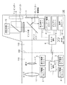
図2は、本発明の実施形態に係る撮像装置の一例としてのレンズ交換式一眼レフデジタルカメラ(以下、単にカメラという)100の構成例を示すブロック図である。カメラ100は、カメラ本体120のレンズマウント105に撮像レンズ110が着脱可能な構成を有する。
(First embodiment)
Hereinafter, preferred and exemplary embodiments of the present invention will be described in detail with reference to the drawings.
FIG. 2 is a block diagram illustrating a configuration example of a lens-interchangeable single-lens reflex digital camera (hereinafter simply referred to as a camera) 100 as an example of an imaging apparatus according to an embodiment of the present invention. The
レンズMPU(マイクロプロセッシングユニット)1は、撮像レンズ110の動作を制御するプログラムを格納したROM、変数を記憶するためのRAM、諸パラメタを記憶するためのEEPROM(電気的消去、書き込み可能メモリ)が内蔵されている。そしてROMに格納されたプログラムを実行することにより、レンズMPU1は撮像レンズ110に係る演算、制御を行う。レンズ駆動ユニット2は、レンズMPU1の指示に従い、撮像レンズ110のレンズ111を駆動する。なお、図2ではレンズ111が1枚のレンズとして示されているが、実際には、撮像レンズの合焦状態を調節するためのフォーカスレンズを含む複数のレンズから構成される。また、撮像レンズ110はズームレンズであってもよい。レンズ駆動ユニット2は、レンズMPU1の指示に従い、フォーカスレンズや画角調整用レンズなどを駆動する。
The lens MPU (microprocessing unit) 1 includes a ROM storing a program for controlling the operation of the
絞り駆動ユニット3は、レンズMPU1の指示に従い、撮像レンズ110が有する絞り112を駆動する。レンズ情報検出ユニット4は、撮像レンズ110の情報(例えば、現在のレンズ位置や絞り値、撮像レンズ110がズームレンズである場合にはその焦点距離(画角)など)を検出する。光学情報テーブル5は、自動焦点調節を行うために必要な、撮像レンズ110の光学情報を記憶するためのテーブルである。撮像レンズ110は、中央の点線で示されるレンズマウント105を介して、カメラ本体120と接続される。
The aperture driving unit 3 drives the
カメラMPU6は、カメラ本体120に係る演算、制御を行い、レンズマウント105が有する信号線を介してレンズMPU1と通信可能に接続される。カメラMPU6は、レンズMPU1に対し、例えば現在のレンズ位置又は焦点距離の取得や、撮像レンズ110ごとに固有の光学情報の取得等を要求することができる。
The camera MPU 6 performs calculation and control related to the
カメラMPU6内にはカメラ動作を制御するプログラムを格納したROM、変数を記憶するためのRAM、諸パラメタを記憶するためのEEPROM(電気的消去、書き込み可能メモリ)が内蔵されている。そしてROMに格納されたプログラムを実行することにより、後述の焦点検出処理を始めとしたカメラ本体120の動作を実現する。第1及び第2の実施形態の焦点検出処理において、カメラMPU6は、焦点検出に用いる輝度情報を測光/光源検知ユニット10から取得し、焦点検出ユニット7を用いて焦点検出処理を実行する。
The
焦点検出ユニット7はサブミラーで反射された被写体像から被写体のピントずれ量を検出するためのAFセンサを含み、AFセンサの読み出し完了をカメラMPU6に通知する。焦点検出ユニット7の動作の詳細については後述する。
The focus detection unit 7 includes an AF sensor for detecting the focus shift amount of the subject from the subject image reflected by the sub mirror, and notifies the
シャッター駆動ユニット8は、カメラMPU6の制御に従い、図示しないシャッターの駆動及び、ミラーの駆動を行う。ダイヤルユニット9は、カメラ本体120に対してユーザが、連続撮像速度(連写速度)、シャッター速度、絞り値、撮像モード等の諸設定を行うための操作部である。測光/光源検知ユニット10は、被写体の測光情報および被写体反射光源種別の情報を得る。撮像面11は撮像素子の受光面であり、メインミラー(及びサブミラー)を光路外に移動させ、シャッターを開くことにより、被写体像を受光する。表示ユニット12は例えばLCDや有機ELディスプレイなどの表示装置を含み、撮像面11で撮像された画像のレビュー表示や、メニュー画面などのGUI表示に用いる。また、連続的に撮像した画像を表示ユニット12に順次表示することで、表示ユニット12を電子ビューファインダーとして機能させることができる。
The shutter drive unit 8 drives a shutter (not shown) and a mirror according to the control of the
SW1は図示しないレリーズボタンの第1ストローク操作(半押し)によりオンするスイッチ、SW2はレリーズボタンの第2ストローク操作(全押し)によりオンするスイッチである。 SW1 is a switch that is turned on by a first stroke operation (half press) of a release button (not shown), and SW2 is a switch that is turned on by a second stroke operation (full press) of the release button.
図3(a)は、焦点検出ユニット7に設けられたAFセンサ(ラインセンサ)の配置例を示す平面図である。図中の複数のラインセンサのうち、センサ301a及び301bは、ファインダー中央に配置されたAFフレームに対応した横線検知用のセンサである。また、センサ302a及び302bは、ファインダー中央に配置されたAFフレームに対応した縦線検知用のセンサである。センサ301a及び301b(302a及び302b)は、焦点検出ユニット7にて分光された2像(A像及びB像)を受光し、各画素で受光した光量に応じた信号を出力する。
FIG. 3A is a plan view illustrating an arrangement example of AF sensors (line sensors) provided in the focus detection unit 7. Among the plurality of line sensors in the figure,
図3(b)は図3(a)に示した焦点検出ユニット7のラインセンサ配置に対応する、撮像面11上での焦点検出領域を示す。たとえばラインセンサ301a及び301bを用いた位相差検出方式での自動焦点検出領域は311であり、ラインセンサ302a及び302b用いた位相差検出方式で自動焦点検出領域は312となる。
FIG. 3B shows a focus detection area on the
図3(c)は、図3(b)に示した焦点検出範囲に、測光/光源検知ユニット10の測光センサの分割領域を重ねて示したものである。例えば、焦点検出領域311および312に対応する測光センサの検出領域は321となる。
FIG. 3C shows the divided area of the photometry sensor of the photometry / light
一般に位相差検出方式の焦点検出ユニット7に用いられる光学系では、特定の波長域(例えばd線(587nm)を中心とした400nm〜650nm)で、色収差などの諸収差の補正が行われる。このため、可視波長域(約360〜約830nm)以外の波長域では光源の種類に応じてピントずれ量の補正を行う必要がある。 In general, in an optical system used for the focus detection unit 7 of the phase difference detection method, various aberrations such as chromatic aberration are corrected in a specific wavelength range (for example, 400 nm to 650 nm centered on the d-line (587 nm)). For this reason, in the wavelength range other than the visible wavelength range (about 360 to about 830 nm), it is necessary to correct the focus shift amount according to the type of the light source.
本実施形態では、位相差検出領域に対応した測光分割領域における光源検出処理の結果に応じてピントずれ量を補正する。この光源検出処理は後述するようにカメラMPU6が測光/光源検知ユニット10を用いて実行する。
In the present embodiment, the focus shift amount is corrected according to the result of the light source detection process in the photometric division area corresponding to the phase difference detection area. This light source detection process is executed by the
測光/光源検知ユニット10は、ペンタミラーからの光束に基づき測光センサを介して測光処理を行う。図4(a)は、本実施形態の測光/光源検知ユニット10が有する測光センサの断面構成例を示す。401は光束の受光面であり、それぞれ分光感度特性の異なる2面の受光層402および403が、受光面から異なる深さに構成された多層構造を有する。測光/光源検知ユニット10は、測光センサが有する2つの受光層402、403のうち、受光層402で得られた出力に基づき被写体の測光情報を得ると同時に、受光層402と403との出力の差分によって被写体からの反射光のエネルギー特性を得る。上述の通り、このような多層構造の測光センサを用いることで、測光センサの実装スペースを削減可能な上、測光センサの読み出し処理に係る負荷を軽減することができる。
The photometry / light
ここで、被写体反射光のエネルギー特性を得る方法について説明する。
まず、従来の、単層構造の2つの測光センサを用いた場合の分光感度特性について図4(c)を用いて説明する。特許文献2では、2つの測光センサの受光面内の1つの受光素子面に着色することで、互いに異なる分光感度特性を得ている。このような構成では、比較的分光感度特性を分離しやすいため、分光感度特性を図4(c)に示す(i)および(ii)のような分光感度特性を設定する。すなわち、図4(c)の(iii)に示す、光学バンドパスフィルタを通過させて得られる光束から、非着色受光面では400nm〜700nmの周波数成分を、着色受光面では600nm〜700nmの周波数成分をそれぞれ検出する。
Here, a method for obtaining the energy characteristic of the subject reflected light will be described.
First, spectral sensitivity characteristics when two conventional photometric sensors having a single layer structure are used will be described with reference to FIG. In
一方で、本実施形態の測光センサの受光層402及び403の分光感度特性を、図4(b)の(i)及び(ii)に示す。図4(a)に示したように、深さ方向に2つ以上の受光層を設けた構成では、各々の受光層の分光感度特性を明確に分離することは構造上困難である。しかし、たとえば図4(b)の(i)及び(ii)に示すように、550nm〜700nmの長波長成分を主に検出する受光層402と、450nm〜550nmの短波長成分を主に検出する受光層403とを設けることができる。
On the other hand, the spectral sensitivity characteristics of the light receiving layers 402 and 403 of the photometric sensor of this embodiment are shown in (i) and (ii) of FIG. As shown in FIG. 4A, in the configuration in which two or more light receiving layers are provided in the depth direction, it is structurally difficult to clearly separate the spectral sensitivity characteristics of each light receiving layer. However, for example, as shown in (i) and (ii) of FIG. 4B, the
そして、長波長成分及び短波長成分のエネルギー特性の差分値あるいは相対比によって、蛍光灯下、外光曇天下、AF基準光下などの被写体反射光源の種類を判別することができる。 The type of subject reflection light source such as under fluorescent lamp, under external light cloudy, or under AF reference light can be determined based on the difference value or relative ratio of the energy characteristics of the long wavelength component and the short wavelength component.
図4(d)はいくつかの撮像シーンでの被写体反射光についてのエネルギー特性差分値と、ピントずれ補正量(補正係数)との関係を示している。ここでエネルギー特性差分値とは、例えば本実施形態であれば、図4の2層構造の測光センサの受光層402及び403それぞれの出力値の差分値を使用する。受光層402及び403はそれぞれがフォトダイオードを有しており、それぞれのフォトダイオードを流れる電流は、それぞれに設けられたダイオードによって対数圧縮されて電圧として出力される。上述の通り、2層の受光層402,403はそれぞれ異なる分光感度を有しており、測光結果として得られるそれぞれの対数圧縮された電圧値をデジタル値に変換し、これらデジタル値の差分値に所定の補正を加えて正規化した値をエネルギー特性差分値として得る。そしてエネルギー差分特性値の大小によって赤外成分を多く含む長波長成分、赤外成分が比較的少ない短波長成分の含有情報が分かり、これによって被写体反射光源の種類を判別する。そして図4(d)では、蛍光灯下での被写体反射光による長波長成分と短波長成分とのエネルギー特性差分値は21程度であり、その時のピントずれ補正量を1.0倍として扱うことを示している。同様に晴天下でのエネルギー特性差分値は17程度であり、補正係数は約0.4倍である。これは、蛍光灯下での補正量を1.0倍とした時の約0.4倍の補正量が生じる事を示している。 FIG. 4D shows the relationship between the energy characteristic difference value with respect to the object reflected light in several imaging scenes and the focus shift correction amount (correction coefficient). Here, as the energy characteristic difference value, for example, in this embodiment, the difference value between the output values of the light receiving layers 402 and 403 of the two-layer photometric sensor of FIG. 4 is used. Each of the light receiving layers 402 and 403 includes a photodiode, and the current flowing through each photodiode is logarithmically compressed by the diode provided in each of the photodiodes and output as a voltage. As described above, the two light receiving layers 402 and 403 have different spectral sensitivities, and each logarithmically compressed voltage value obtained as a photometric result is converted into a digital value, and the difference value between these digital values is converted. A value normalized by applying a predetermined correction is obtained as an energy characteristic difference value. The content information of the long wavelength component that contains a large amount of infrared components and the short wavelength component that contains a relatively small amount of infrared components can be found based on the magnitude of the energy difference characteristic value. In FIG. 4D, the energy characteristic difference value between the long wavelength component and the short wavelength component due to the subject reflected light under the fluorescent lamp is about 21, and the focus deviation correction amount at that time is handled as 1.0 times. Is shown. Similarly, the energy characteristic difference value in fine weather is about 17, and the correction coefficient is about 0.4 times. This indicates that a correction amount of about 0.4 times occurs when the correction amount under the fluorescent lamp is 1.0 times.
このように、異なる分光感度特性を有する受光層のエネルギー特性の出力を用いることにより、被写体反射光の種類は概ね判別可能である。しかしながら、図4(b)に示したような分光感度特性では、長波長成分のみを抽出すべき受光層においても550nm前後の短波長成分を含み、短波長成分のみを抽出すべき受光層においても700nm前後の長波長成分を含んでしまう。その結果、図4(d)の蛍光灯下と晴天日陰のように、ピントずれ補正量は異なるにも関わらず、ほぼ同じエネルギー特性差分値(21程度)を示すケースが発生する。このような分光感度特性の一部重複は、本実施形態で用いている測光センサのように、多層構造の測光センサを用いる場合に起こりうる。 As described above, by using the output of the energy characteristic of the light receiving layer having different spectral sensitivity characteristics, the type of the reflected light from the subject can be roughly determined. However, in the spectral sensitivity characteristics as shown in FIG. 4B, even in the light receiving layer from which only the long wavelength component should be extracted, the light receiving layer that includes the short wavelength component of around 550 nm and from which only the short wavelength component should be extracted. Long wavelength components around 700 nm are included. As a result, there is a case where the same energy characteristic difference value (about 21) is generated even though the focus shift correction amount is different, such as under the fluorescent lamp in FIG. Such partial overlap of spectral sensitivity characteristics can occur when a multi-layered photometric sensor is used, such as the photometric sensor used in the present embodiment.
次に、本実施形態のカメラ100における自動焦点検出処理について、図1のフローチャートを用いて説明する。
図2で示したカメラ本体120のスイッチSW1がONになると、カメラMPU6はS101で、焦点検出ユニット7が有するラインセンサのうち、ユーザーが選択した焦点検出領域に対応するラインセンサでの電荷蓄積を行う。そして、カメラMPU6は、ラインセンサに蓄積された電荷を画素毎に読み出し、ラインセンサ毎の被写体像を取得する。
Next, automatic focus detection processing in the
When the switch SW1 of the camera
S102でカメラMPU6は、一対のラインセンサで取得した一対の被写体像の位相差に基づき、公知の焦点検出方法によってピントずれ量を演算する。例えばカメラMPU6は、図3(a)に示した一対のラインセンサ301a及び301bで得られた2像のずれ(bit数)に対し、センサピッチ(mm)とオートフォーカス系の基線長などの光学係数を乗じ、撮像面11上でのピントずれ量(mm)を求める。
In S102, the
S103でカメラMPU6は、測光/光源検知ユニット10が有する測光センサの、第1の受光層402および第2の受光層403の測光値を読み出す。
In S <b> 103, the
S104で、輝度検出手段としてのカメラMPU6は、受光層402で得られた可視光側波長の測光結果により画面全体に対する被写体輝度BVを求める。そして、カメラMPU6は、設定されているISO感度SVと被写体輝度BVとを加算して露出値EVを求め、公知の方法で、絞り値AVおよびシャッター速度TVとを算出する。さらに、カメラMPU6は、ピントずれ量を求めたラインセンサ301a及び301bに対応した測光領域321についての被写体輝度BVと、受光層402と受光層403とから得た測光値の差分値とを内部のRAMに記憶する。
In S <b> 104, the
S105でカメラMPU6は、S104で得た、測光領域321についての被写体輝度BV及び測光差分値に基づいて、光源に応じたピントずれ補正係数を演算する。詳細は図1(b)を用いて後述する。
In S105, the
S106でカメラMPU6は、レンズMPU1に対し、撮像レンズ110の色収差に関する情報の送信を要求する。レンズMPU1はこの要求に応答して、撮像レンズ110の現在の焦点距離(画角であってもよい)およびレンズ位置(被写体距離であってもよい)をレンズ情報検出ユニット4を通じて取得する。そしてレンズMPU1は、現在の焦点距離及びレンズ位置を用いて光学情報テーブル5に記憶された色収差テーブルを参照して撮像レンズ110の現在の色収差データを取得し、カメラMPU6に返送する。
In S106, the camera MPU6 requests the lens MPU1 to transmit information regarding chromatic aberration of the
表1は、撮像レンズ110が焦点距離35〜70mmのズームレンズである場合に、光学情報テーブル5に記憶される色収差テーブルの例を示す。色収差テーブルは、白昼下で検出されるピントずれ量に対する、短波長領域の光を多く照射する光源として代表的な蛍光灯下での検出されるピントずれ量の差(割合)を、レンズの焦点距離と被写体距離とに応じて示している。こうした色収差テーブルは、個々の撮像レンズ110が有しており、基本的には光学設計で決定される値であるため、撮像レンズ110が有するROMに記録する。しかし、製造上の誤差を考慮し、個々のレンズに応じた修正を加えるためにEEPROMやフラッシュROMなどの書き換え可能な不揮発性メモリに記憶しても良い。
Table 1 shows an example of a chromatic aberration table stored in the optical information table 5 when the

S107でカメラMPU6は、S106で得た撮像レンズ110の色収差データに対して、S105で求めた補正係数を乗じてピントずれ補正量を演算する。さらにS108でカメラMPU6は、S102で得たピントずれ量に、S107で演算したピントずれ補正量を加算し、最終的なピントずれ量(補正後のピントずれ量)を演算する。
In S107, the
S109でカメラMPU6は、補正後のピントずれ量が予め定めた合焦範囲内、たとえば
|補正後のピントずれ量|≦Fδ×1/4 (F:レンズ絞り値、δ:定数)
であるなら合焦と判定し、S110でSW2がONであればS121に遷移する。S110でSW2がONでなければ、カメラMPU6はさらにS112でSW1の状態を確認し、SW1がONのままであればS110へ処理を戻し、SW1がOFFであれば自動焦点検出処理を終了する。
In S109, the
If it is, it determines with focusing, and if SW2 is ON in S110, it will transfer to S121. If SW2 is not ON in S110, the
一方、S109で補正後のピントずれ量が予め定めた合焦範囲内でなければ、カメラMPU6はS111で、レンズ駆動ユニット2を通じて、補正後のピントずれ量に応じてフォーカスレンズの駆動を行ない、撮像レンズ110の位置を調整する。そして、カメラMPU6は、S109で合焦と判定されるまで、S102からの動作を繰り返す。
On the other hand, if the defocus amount after correction in S109 is not within the predetermined focus range, the
S121以降は撮像処理である。S121でカメラMPU6は、メインミラーを駆動して撮像光路外に退避させるとともに、絞り112をS104で決定した絞り値AVに駆動するようレンズMPU1に指示する。レンズMPU1は、この指示に応答して、絞り駆動ユニット3を通じて絞り112を絞り値AVとなるように駆動する。メインミラーの退避が完了すると、カメラMPU6はS122でシャッター駆動ユニット8を通じてシャッター先幕の駆動を開始させる。
S121 and subsequent steps are imaging processing. In S121, the camera MPU6 drives the main mirror to retract outside the imaging optical path and instructs the lens MPU1 to drive the
S104で決定したシャッター速度TVに相当する開放時間が経過すると、カメラMPU6はS123でシャッター駆動ユニット8を通じてシャッター後幕の駆動を開始させ、S124でメインミラーを撮像光路中に戻して撮像動作を終了する。撮像後に行われる画像処理及び記録処理に関しては本発明と直接関係がないため説明を省略する。
When the opening time corresponding to the shutter speed TV determined in S104 has elapsed, the
次に図1(b)のフローチャートを用いて、図1(a)のS105で行う、光源に応じたピントずれ補正係数の演算処理について説明する。
一般に、以下の表2に示すように、室内及び屋外の明るさは照明の具合や天候などの気象条件、時刻などによりさまざまに変化するが、蛍光灯下と太陽光下では照度(ルクス)が大きく異なる。例えば、照明のある室内における照度は800ルクスから1000ルクス前後であるのに対し、昼間の曇天下における照度は32000ルクス程度であり、昼間の晴天下の照度は100000ルクスに達する。
Next, using the flowchart of FIG. 1B, the calculation process of the focus deviation correction coefficient corresponding to the light source performed in S105 of FIG.
In general, as shown in Table 2 below, the brightness of indoors and outdoors varies depending on lighting conditions, weather conditions such as weather, time, etc., but the illuminance (lux) is under fluorescent light and sunlight. to differ greatly. For example, the illuminance in a room with illumination is about 800 lux to about 1000 lux, whereas the illuminance under cloudy daytime is about 32,000 lux, and the illuminance under sunny daylight reaches 100,000 lux.
そこで、本実施形態では、被写体輝度BVを参照することにより、被写体を照射する光源(被写体反射光源)が蛍光灯であるか太陽光であるかを判別する。
まずS131でカメラMPU6は、S104にて得られた測光領域321の被写体輝度BVと所定の第1の閾値との大小を比較する。カメラMPU6は、図4(e)に示すように、被写体輝度BVが第1の閾値よりも小さければ被写体反射光源は蛍光灯であると判定して、S132にて最大補正係数曲線(蛍光灯補正係数曲線)を採用する。この最大補正係数とは、図4(d)の(i)で示した補正曲線と、長波長成分及び短波長成分のエネルギー特性差分値とから決定される係数である。
Therefore, in the present embodiment, by referring to the subject brightness BV, it is determined whether the light source (subject reflection light source) that irradiates the subject is a fluorescent lamp or sunlight.
First, in step S131, the
S133でカメラMPU6は、S104で取得した測光領域321の被写体輝度BVと所定の第2の閾値(第1の閾値<第2の閾値である)との大小を比較する。カメラMPU6は、図4(e)に示すように、被写体輝度情報が第2の閾値よりも大きければ被写体反射光源は太陽光であると判定して最小補正係数曲線(晴天日陰補正係数曲線)を採用する。この最小補正係数とは図4(d)の(ii)で示した補正曲線と、長波長成分及び短波長成分のエネルギー特性差分値とから決定される係数である。
In S133, the
被写体輝度BVが第1の閾値以上、第2の閾値以下の場合、カメラMPU6は、被写体輝度BVと第1及び第2の閾値との大小関係に応じて、補正曲線(ii)から補正曲線(i)の間で線形的に補間した補正係数を求める。具体的には被写体輝度BVが図4(e)のXの値である場合、対応する補正係数αは
α=(最大補正係数−最小補正係数)・(X−第1の閾値)/(第2の閾値−第1の閾値)
によって求める。
When the subject brightness BV is greater than or equal to the first threshold value and less than or equal to the second threshold value, the
Ask for.
なお、本実施形態のセンサの分光感度特性では蛍光灯下と晴天日陰とを区別するものであり、最大補正係数とは蛍光灯下での補正係数、最小補正係数とは晴天日陰下での補正係数のことである。BV値によって撮影シーンが蛍光灯下であるか晴天日陰であるかを判定し、補正すべきピントズレ量の補正曲線を選択的に適用することが狙いであるので、光源の判別を被写体BVで行う事で被写体反射光源のみに着目したピントズレ補正量を算出できる。しかし、多くの撮影シーンにおいては被写体領域のBV値も画面全体のBV値も大きな差はないので、画面全体についての被写体輝度BVを用いて光源の判別を行ってもよい。 Note that the spectral sensitivity characteristics of the sensor of this embodiment distinguish between fluorescent light and clear sky shade. The maximum correction coefficient is the correction coefficient under fluorescent light, and the minimum correction coefficient is the correction under clear sky shade. It is a coefficient. The objective is to determine whether the shooting scene is under a fluorescent light or in the shade with a BV value, and to selectively apply a correction curve for the defocus amount to be corrected, so that the light source is determined on the subject BV. Thus, it is possible to calculate the focus shift correction amount focusing only on the subject reflection light source. However, in many shooting scenes, there is no significant difference between the BV value of the subject area and the BV value of the entire screen, and the light source may be determined using the subject brightness BV for the entire screen.
以上の判定処理により、図4(d)に示すように長波長成分、短波長成分のエネルギー特性差分値が同じであっても、光源の種類を判別して適切な補正係数を得ることができる。つまり、被写体輝度が比較的低い場合は室内での撮像であると判断し、蛍光灯下や蛍光灯下の人肌などの撮像シーンに適したピントずれ量補正係数曲線(ii)を採用することができる。また、被写体輝度が比較的高い場合は室外での撮像であると判断し、晴天下や晴天日陰下などの撮像シーンに適したピントずれ量補正係数曲線(i)を採用することができる。 By the above determination processing, even if the energy characteristic difference values of the long wavelength component and the short wavelength component are the same as shown in FIG. 4D, it is possible to determine the type of the light source and obtain an appropriate correction coefficient. . In other words, if the subject brightness is relatively low, it is determined that the image is taken indoors, and a focus deviation correction coefficient curve (ii) suitable for an imaging scene such as a fluorescent light or a human skin under the fluorescent light is adopted. Can do. In addition, when the subject brightness is relatively high, it is determined that the image is taken outside the room, and a focus shift amount correction coefficient curve (i) suitable for an imaging scene such as under a clear sky or under a clear sky can be employed.
以上説明したように、本実施形態によれば、異なる分光感度特性を有する複数の受光層を有する多層構成の測光センサにより被写体反射光源を判別する場合に、各受光層で得られるエネルギー特性の差分値に加え、被写体輝度を考慮して光源の種類を判別する。そのため、各受光層で得られるエネルギー特性の差分値だけでは光源の種類が判別できない場合も、より適切にピントずれ量を補正することが可能になる。
従って、多層構成の測光センサの利点である省スペース性やセンサ読み出し処理の低負荷性と、適切なピントずれ量の補正とを両立させることが可能となる。
As described above, according to the present embodiment, when the subject reflection light source is discriminated by the multi-layer photometric sensor having a plurality of light receiving layers having different spectral sensitivity characteristics, the difference in energy characteristics obtained in each light receiving layer. In addition to the value, the type of light source is determined in consideration of the subject brightness. Therefore, even when the type of the light source cannot be determined only by the difference value of the energy characteristics obtained in each light receiving layer, it becomes possible to correct the focus shift amount more appropriately.
Accordingly, it is possible to achieve both the space saving and the low load of the sensor reading process, which are the advantages of the multi-layer photometric sensor, and the appropriate correction of the focus shift amount.
なお、本実施形態においては、最も説明および理解が容易な例として、暗い光源である蛍光灯と、明るい光源である太陽光との判別を行う構成について説明した。しかし、本発明はこれら特定の光源の判別に限定されず、被写体輝度によって判別可能な有意な差を有する光源の判別に適用可能であることは容易に理解されよう。例えば、一般に室内で用いられる人工光源(電球やLEDなど)は蛍光灯と同様に太陽光に対して輝度が低いため、各受光層で得られるエネルギー特性の差分値だけでは光源の種類が判別できない場合、被写体輝度を考慮することは有用である。 In the present embodiment, as an example that is easiest to explain and understand, a configuration has been described in which a fluorescent lamp that is a dark light source and sunlight that is a bright light source are discriminated. However, it will be easily understood that the present invention is not limited to the discrimination of these specific light sources, and can be applied to the discrimination of light sources having a significant difference that can be discriminated by subject luminance. For example, since artificial light sources (such as light bulbs and LEDs) that are generally used indoors have a low luminance relative to sunlight, as with fluorescent lamps, the type of light source cannot be determined only by the difference value of the energy characteristics obtained in each light receiving layer. In this case, it is useful to consider subject brightness.
また、被写体輝度BVを測光センサのうち可視波長側の分光感度特性を有する受光層402の出力に基づいて求めたが、両方の受光層402,403の出力に基づいて求めてもよい。また、外測測光センサを別途設けて被写体輝度を求めてもよい。
Further, although the subject brightness BV is obtained based on the output of the
(第2の実施形態)
次に、本発明の第2の実施形態について説明する。本実施形態は、被写体輝度と閾値との大小関係により光源の種類を判別する代わりに、ライブビュー撮像時に撮像面でフリッカを検出することにより、光源の種類を判別することを特徴とする。ライブビュー撮像とは、表示ユニット12を電子ビューファインダーとして機能させる際の撮像のように、連続的な(例えば30回/秒)撮像である。実質的には動画撮像と考えてもよい。カメラ100の構成は第1の実施形態と同様で良いため、以下、図5のフローチャートを用いて本実施形態における自動焦点検出処理について説明する。図5において、図1と同じ処理を行うステップには同じ参照数字を付して説明を省略する。
(Second Embodiment)
Next, a second embodiment of the present invention will be described. The present embodiment is characterized in that the type of light source is determined by detecting flicker on the imaging surface during live view imaging instead of determining the type of light source based on the magnitude relationship between subject brightness and threshold. The live view imaging is continuous (for example, 30 times / second) imaging as in imaging when the
ここでは、カメラ100が撮像スタンバイ状態であり、かつ表示ユニット12を電子ビューファインダーとして機能させるライブビューモードで動作しているものとする。ライブビューモードでは、連続的な撮像を行うため、カメラMPU6はメインミラーを撮像光路外に退避させ、撮像面11に撮像レンズ110からの光束が入射するようにする。
Here, it is assumed that the
S501では、撮像面11の情報(すなわち、撮像された画像)に基づき、フリッカ(フリッカ成分)の有無を検出する。ライブビューモードに撮像された画像(ライブビュー画像)からフリッカを検出する方法に特に制限はなく、例えば、特開2009−130531に記載されるような、任意の公知技術を用いることができる。 In S501, the presence / absence of flicker (flicker component) is detected based on the information on the imaging surface 11 (that is, the captured image). There is no particular limitation on the method for detecting flicker from an image captured in the live view mode (live view image), and any known technique as described in, for example, Japanese Patent Application Laid-Open No. 2009-130531 can be used.
S502でカメラMPU6は、撮像画像からフリッカ成分が検知されたか、すなわち、被写体反射光源がフリッカ光源(代表的には蛍光灯)であるかを判定する。そして、カメラMPU6は、フリッカが検知されたと判定した場合には、蛍光灯下のピントずれ量を補正すべく図4(d)の(i)に示す最大補正係数曲線を採用する(S503)。一方、フリッカが検出されないと判定した場合、カメラMPU6は図4(d)の(ii)に示す最小補正係数曲線を採用する(S504)。
In S502, the
S505でカメラMPU6はSW1がONか否かを判定し、ONでなければS501からの処理を繰り返す。一方、SW1がONであれば、カメラMPU6は焦点検出ユニット7を用いた自動焦点検出処理を行うため、S506でメインミラーを撮像光路中に戻す。以降、S101〜S103及びS106の動作は第1の実施形態と同様なので説明を省略する。
In step S505, the
S507でカメラMPU6は、S503もしくはS504で決定した補正係数曲線および、S103で得た長波長成分と短波長成分とのエネルギー特性の差分値とから、ピントずれ量の補正係数を演算する。そして、S106で得た撮像レンズ110の色収差データに対して補正係数を乗じてピントずれ補正量を演算する。
以後、S108からの処理は第1の実施形態と同様であるため説明を省略する。
In S507, the
Henceforth, since the process from S108 is the same as that of 1st Embodiment, description is abbreviate | omitted.
このように、本実施形態では、ライブビューモードで撮像された画像から被写体反射光源がフリッカ光源かどうかを検出することにより、光源の種類を判別する。本実施形態によっても、第1の実施形態と同様の効果が実現できる。 As described above, in this embodiment, the type of the light source is determined by detecting whether or not the subject reflection light source is a flicker light source from an image captured in the live view mode. According to this embodiment, the same effect as that of the first embodiment can be realized.
(その他の実施形態)
また、本発明は、以下の処理を実行することによっても実現される。即ち、上述した実施形態の機能を実現するソフトウェア(プログラム)を、ネットワーク又は各種記憶媒体を介してシステム或いは装置に供給し、そのシステム或いは装置のコンピュータ(またはCPUやMPU等)がプログラムを読み出して実行する処理である。
(Other embodiments)
The present invention can also be realized by executing the following processing. That is, software (program) that realizes the functions of the above-described embodiments is supplied to a system or apparatus via a network or various storage media, and a computer (or CPU, MPU, or the like) of the system or apparatus reads the program. It is a process to be executed.
なお、上述の実施形態ではレンズ交換型のカメラに本発明を適用した例を説明したが、レンズを交換できないカメラであっても位相差検出方式の自動焦点検出装置を用いる限りは同様の課題は存在し、また本発明を適用して課題を解決することが可能である。本発明は位相差検出方式の自動焦点検出装置を備えるいかなる撮像装置にも適用可能である。 In the above-described embodiment, the example in which the present invention is applied to the interchangeable lens camera has been described. However, even if the camera cannot replace the lens, the same problem occurs as long as the phase difference detection type automatic focus detection apparatus is used. It exists and can solve the problem by applying the present invention. The present invention can be applied to any imaging apparatus including a phase difference detection type automatic focus detection apparatus.
Claims (3)
前記被写体像の光束のうち、前記測光手段が受光する光束とは別の光束を受光し、前記撮像レンズのピントずれ量を位相差検出方式で検出する焦点検出手段と、
前記測光手段により検出された被写体輝度の大きさによって光源の種類を判別する判別手段であって、前記測光手段により検出された被写体輝度が第1の閾値よりも大きい場合には光源が太陽光であると判別し、前記測光手段により検出された被写体輝度が前記第1の閾値よりも小さい第2の閾値より小さい場合には光源が蛍光灯であると判別する判別手段と、
前記判別手段が判別した光源の種類に応じた補正係数曲線と、前記撮像レンズを介した被写体像について前記測光手段の前記複数の受光層の各々の出力から得られるエネルギー特性の差分値とから、補正係数を演算する演算手段と、
前記撮像レンズの色収差データを取得する取得手段と、
前記焦点検出手段が検出した前記撮像レンズのピントずれ量を、前記補正係数で補正した前記色収差データによって補正する補正手段と、
前記補正手段が補正したピントずれ量に従って前記撮像レンズの位置を調整する調整手段とを有し、
前記演算手段は、前記判別手段により光源が太陽光であると判別された場合には、第1の補正係数曲線を採用し、前記判別手段により光源が蛍光灯であると判別された場合には、第2の補正係数曲線を採用し、前記判別手段により、前記測光手段により検出された被写体輝度が前記第2の閾値以上前記第1の閾値以下であると判別された場合には、前記第1の補正係数曲線及び前記第2の補正係数曲線の間で補間した補正係数曲線を採用することを特徴とする撮像装置。 A multi-layer photometric means having a plurality of light receiving layers for receiving a part of the light flux of the subject image via the imaging lens, the photometric means for detecting the subject brightness from at least one output of the plurality of light receiving layers;
A focus detection unit that receives a light beam different from the light beam received by the photometry unit from the light beam of the subject image, and detects a focus deviation amount of the imaging lens by a phase difference detection method;
A discriminating means for discriminating the type of the light source based on the magnitude of the subject brightness detected by the photometry means, and when the subject brightness detected by the photometry means is greater than a first threshold, the light source is sunlight. Discriminating means for discriminating that the light source is a fluorescent lamp when the subject luminance detected by the photometric means is smaller than a second threshold value smaller than the first threshold value ;
From the correction coefficient curve according to the type of the light source determined by the determination unit , and the difference value of the energy characteristics obtained from the output of each of the plurality of light receiving layers of the photometry unit for the subject image via the imaging lens , a calculating means for calculating a compensation coefficient,
Obtaining means for obtaining chromatic aberration data of the imaging lens;
Correction means for correcting the focus shift amount of the imaging lens detected by the focus detection means with the chromatic aberration data corrected with the correction coefficient;
Possess and adjustment means for adjusting the position of the imaging lens according to the defocus amount which the correction means has corrected,
The calculating means adopts the first correction coefficient curve when the light source is determined to be sunlight by the determining means, and when the light source is determined to be a fluorescent lamp by the determining means. When the second correction coefficient curve is employed and the determining means determines that the subject brightness detected by the photometric means is not less than the second threshold and not more than the first threshold, An imaging apparatus that employs a correction coefficient curve interpolated between one correction coefficient curve and the second correction coefficient curve .
前記被写体像の光束のうち、前記測光手段が受光する光束とは別の光束を受光し、前記撮像レンズのピントずれ量を位相差検出方式で検出する焦点検出手段と、
を有する撮像装置の制御方法であって、
判別手段が前記測光手段により検出された被写体輝度の大きさによって光源の種類を判別する判別工程であって、前記測光手段により検出された被写体輝度が第1の閾値よりも大きい場合には光源が太陽光であると判別し、前記測光手段により検出された被写体輝度が前記第1の閾値よりも小さい第2の閾値より小さい場合には光源が蛍光灯であると判別する判別工程と、
前記判別工程で判別された光源の種類に応じた補正係数曲線と、前記被写体輝度と、前記撮像レンズを介した被写体像について前記測光手段の前記複数の受光層の各々の出力から得られるエネルギー特性の差分値とから、演算手段が補正係数を演算する演算工程と、
取得手段が前記撮像レンズの色収差データを取得する取得工程と、
補正手段が、前記焦点検出手段の検出した前記撮像レンズのピントずれ量を、前記補正係数で補正した前記色収差データによって補正する補正工程と、
調整手段が、前記補正工程で補正されたピントずれ量に従って前記撮像レンズの位置を調整する調整工程とを有し、
前記演算工程では、前記判別工程により光源が太陽光であると判別された場合には、第1の補正係数曲線を採用し、前記判別工程により光源が蛍光灯であると判別された場合には、第2の補正係数曲線を採用し、前記判別工程により前記測光手段により検出された被写体輝度が前記第2の閾値以上前記第1の閾値以下であると判別された場合には、前記第1の補正係数曲線及び前記第2の補正係数曲線の間で補間した補正係数曲線を採用することを特徴とする撮像装置の制御方法。 A multi-layer photometric means having a plurality of light receiving layers for receiving a part of the light flux of the subject image via the imaging lens, the photometric means for detecting the subject brightness from at least one output of the plurality of light receiving layers;
A focus detection unit that receives a light beam different from the light beam received by the photometry unit from the light beam of the subject image, and detects a focus deviation amount of the imaging lens by a phase difference detection method;
A method for controlling an imaging apparatus having:
A determining step in which the determining means determines the type of the light source based on the magnitude of the subject brightness detected by the photometric means, and if the subject brightness detected by the photometric means is greater than a first threshold, the light source is A determining step of determining that the light source is a fluorescent lamp when the subject brightness detected by the photometric means is smaller than a second threshold value that is smaller than the first threshold value ;
Energy characteristics obtained from the output of each of the plurality of light receiving layers of the photometric means for the correction coefficient curve according to the type of the light source determined in the determination step, the subject brightness, and the subject image via the imaging lens and a difference value of a calculation step of calculating means for calculating a compensation coefficient,
An acquisition step in which the acquisition means acquires chromatic aberration data of the imaging lens;
A correction step in which the correction unit corrects the focus shift amount of the imaging lens detected by the focus detection unit by the chromatic aberration data corrected by the correction coefficient;
Adjusting means, it possesses an adjusting step of adjusting a position of the imaging lens according to the defocus amount corrected by said correction step,
In the calculation step , when the light source is determined to be sunlight by the determination step, the first correction coefficient curve is adopted, and when the light source is determined to be a fluorescent lamp by the determination step When the second correction coefficient curve is adopted and the subject brightness detected by the photometry means is determined to be not less than the second threshold and not more than the first threshold in the determining step, the first correction coefficient curve is used. And a correction coefficient curve interpolated between the second correction coefficient curve and the second correction coefficient curve .
Priority Applications (1)
| Application Number | Priority Date | Filing Date | Title |
|---|---|---|---|
| JP2009201087A JP5473493B2 (en) | 2009-08-31 | 2009-08-31 | Imaging apparatus and control method thereof |
Applications Claiming Priority (1)
| Application Number | Priority Date | Filing Date | Title |
|---|---|---|---|
| JP2009201087A JP5473493B2 (en) | 2009-08-31 | 2009-08-31 | Imaging apparatus and control method thereof |
Publications (3)
| Publication Number | Publication Date |
|---|---|
| JP2011053377A JP2011053377A (en) | 2011-03-17 |
| JP2011053377A5 JP2011053377A5 (en) | 2012-10-18 |
| JP5473493B2 true JP5473493B2 (en) | 2014-04-16 |
Family
ID=43942457
Family Applications (1)
| Application Number | Title | Priority Date | Filing Date |
|---|---|---|---|
| JP2009201087A Expired - Fee Related JP5473493B2 (en) | 2009-08-31 | 2009-08-31 | Imaging apparatus and control method thereof |
Country Status (1)
| Country | Link |
|---|---|
| JP (1) | JP5473493B2 (en) |
Families Citing this family (4)
| Publication number | Priority date | Publication date | Assignee | Title |
|---|---|---|---|---|
| JP6118058B2 (en) * | 2012-10-02 | 2017-04-19 | キヤノン株式会社 | Solid-state imaging device, imaging apparatus, and control method |
| WO2014080718A1 (en) * | 2012-11-22 | 2014-05-30 | 富士フイルム株式会社 | Image pick-up device and focus control method |
| JP6529214B2 (en) | 2013-10-30 | 2019-06-12 | キヤノン株式会社 | Imaging device |
| CN105791811B (en) * | 2014-09-30 | 2018-11-27 | 宁波舜宇光电信息有限公司 | A kind of three-dimensional test mark version and its design and forming method |
Family Cites Families (3)
| Publication number | Priority date | Publication date | Assignee | Title |
|---|---|---|---|---|
| JP2006071741A (en) * | 2004-08-31 | 2006-03-16 | Olympus Corp | Focus detecting device |
| JP4377840B2 (en) * | 2005-03-31 | 2009-12-02 | イーストマン コダック カンパニー | Digital camera |
| JP4612869B2 (en) * | 2005-06-08 | 2011-01-12 | キヤノン株式会社 | Focus detection device, imaging device, and focusing method |
-
2009
- 2009-08-31 JP JP2009201087A patent/JP5473493B2/en not_active Expired - Fee Related
Also Published As
| Publication number | Publication date |
|---|---|
| JP2011053377A (en) | 2011-03-17 |
Similar Documents
| Publication | Publication Date | Title |
|---|---|---|
| JP5020651B2 (en) | Imaging apparatus and imaging system | |
| US7414231B2 (en) | Focus-state detecting device, image sensing apparatus and image sensing system having same and lens unit mounted thereon | |
| US8150252B2 (en) | Imaging apparatus and imaging apparatus control method | |
| US20140240550A1 (en) | Image capturing apparatus | |
| US7940323B2 (en) | Image-pickup apparatus and control method thereof | |
| US7925150B2 (en) | Camera system, camera body, flash device, and illumination method | |
| JP5473493B2 (en) | Imaging apparatus and control method thereof | |
| JP2006317595A (en) | Optical apparatus and its control method | |
| JP6336337B2 (en) | Imaging apparatus, control method therefor, program, and storage medium | |
| JP2009053568A (en) | Imaging apparatus and imaging system | |
| JP4350199B2 (en) | camera | |
| JP3927655B2 (en) | camera | |
| JP2004004449A (en) | Exposure control system for camera | |
| JP5794665B2 (en) | Imaging device | |
| JP4950634B2 (en) | Imaging apparatus and imaging system | |
| JP5163498B2 (en) | Camera system | |
| JP2006072084A (en) | Automatic focus detecting device and camera system | |
| JP4422442B2 (en) | Digital camera | |
| US10873707B2 (en) | Image pickup apparatus and method, for ensuring correct color temperature based on first or second preliminary light emission of a flash device | |
| JP4928236B2 (en) | Imaging apparatus and imaging system | |
| JP2014137449A (en) | Imaging device, control method and program | |
| JP2005121834A (en) | Imaging method, imaging apparatus, program, and storage medium | |
| JP2008203407A (en) | Imaging apparatus, lens device and imaging system | |
| JP2009003261A (en) | Focus adjustment device, imaging device and focus adjustment method | |
| JP2005165186A (en) | Camera |
Legal Events
| Date | Code | Title | Description |
|---|---|---|---|
| A521 | Request for written amendment filed |
Free format text: JAPANESE INTERMEDIATE CODE: A523 Effective date: 20120830 |
|
| A621 | Written request for application examination |
Free format text: JAPANESE INTERMEDIATE CODE: A621 Effective date: 20120830 |
|
| A977 | Report on retrieval |
Free format text: JAPANESE INTERMEDIATE CODE: A971007 Effective date: 20130520 |
|
| A131 | Notification of reasons for refusal |
Free format text: JAPANESE INTERMEDIATE CODE: A131 Effective date: 20130524 |
|
| A521 | Request for written amendment filed |
Free format text: JAPANESE INTERMEDIATE CODE: A523 Effective date: 20130723 |
|
| A131 | Notification of reasons for refusal |
Free format text: JAPANESE INTERMEDIATE CODE: A131 Effective date: 20131004 |
|
| A521 | Request for written amendment filed |
Free format text: JAPANESE INTERMEDIATE CODE: A523 Effective date: 20131202 |
|
| TRDD | Decision of grant or rejection written | ||
| A01 | Written decision to grant a patent or to grant a registration (utility model) |
Free format text: JAPANESE INTERMEDIATE CODE: A01 Effective date: 20140106 |
|
| A61 | First payment of annual fees (during grant procedure) |
Free format text: JAPANESE INTERMEDIATE CODE: A61 Effective date: 20140204 |
|
| R151 | Written notification of patent or utility model registration |
Ref document number: 5473493 Country of ref document: JP Free format text: JAPANESE INTERMEDIATE CODE: R151 |
|
| LAPS | Cancellation because of no payment of annual fees |