JP6336337B2 - Imaging apparatus, control method therefor, program, and storage medium - Google Patents
Imaging apparatus, control method therefor, program, and storage medium Download PDFInfo
- Publication number
- JP6336337B2 JP6336337B2 JP2014123809A JP2014123809A JP6336337B2 JP 6336337 B2 JP6336337 B2 JP 6336337B2 JP 2014123809 A JP2014123809 A JP 2014123809A JP 2014123809 A JP2014123809 A JP 2014123809A JP 6336337 B2 JP6336337 B2 JP 6336337B2
- Authority
- JP
- Japan
- Prior art keywords
- image information
- infrared light
- imaging apparatus
- light region
- processing
- Prior art date
- Legal status (The legal status is an assumption and is not a legal conclusion. Google has not performed a legal analysis and makes no representation as to the accuracy of the status listed.)
- Active
Links
Images


Description
本発明は、撮像装置及びその制御方法に関する。 The present invention relates to an imaging apparatus and a control method thereof.
人間が知覚できる光は、一般に約400nmから約680nmの範囲(以下可視光域)内の光である。従来、デジタルカメラやデジタルビデオカメラのような撮像装置では、上記範囲内の光のみを取り込むため、撮像用イメージセンサの前に400nm以下の紫外光域の除去フィルタや、680nm以上の赤外光域の除去フィルタ等を配置している。 The light that can be perceived by human beings is generally in the range of about 400 nm to about 680 nm (hereinafter, visible light region). Conventionally, in an imaging apparatus such as a digital camera or a digital video camera, in order to capture only light within the above range, an ultraviolet light removal filter of 400 nm or less or an infrared light range of 680 nm or more is provided in front of the image sensor for imaging. The removal filter etc. are arranged.
ところが一方で、撮像装置で光源の種類によるピントずれを抑制するために、赤外光を検知することが望まれている。例えば、特許文献1では、可視光域と赤外光域を検知する波長成分検出センサを配置し、2つの出力差に応じて焦点検出センサにより検知されたデフォーカス量を補正している。 On the other hand, it is desired to detect infrared light in order to suppress the focus shift due to the type of light source in the imaging apparatus. For example, in Patent Document 1, a wavelength component detection sensor that detects a visible light region and an infrared light region is arranged, and the defocus amount detected by the focus detection sensor is corrected according to two output differences.
しかしながら、特許文献1に開示されたセンサを一眼レフカメラの測光センサとして用いようとすると、以下のような問題が生じる。 However, when the sensor disclosed in Patent Document 1 is used as a photometric sensor of a single-lens reflex camera, the following problems arise.
特許文献1に開示された技術では、赤外光域に感度を持たせたセンサを用いている。そのため、このセンサで撮影用センサの露光量決定演算を行うと、センサ間の赤外光域の感度差によって測光結果にずれが生じる。 In the technique disclosed in Patent Document 1, a sensor having sensitivity in an infrared light region is used. For this reason, when the exposure amount determination calculation of the imaging sensor is performed with this sensor, the photometric result is shifted due to the sensitivity difference in the infrared light region between the sensors.
本発明は上述した課題に鑑みてなされたものであり、その目的は、赤外光域及び可視光域に感度を有する複数の画素を有する測光センサを用いた処理を良好に行うことができる撮像装置を提供することである。 The present invention has been made in view of the above-described problems, and an object of the present invention is to perform imaging using a photometric sensor having a plurality of pixels having sensitivity in the infrared light region and the visible light region. Is to provide a device.
本発明に係わる撮像装置は、赤外光域及び可視光域に感度を有する複数の画素を有する測光センサと、前記測光センサを複数の画素群に分け、該複数の画素群ごとに赤外光域の画像情報と可視光域の画像情報を取得する取得手段と、前記複数の画素群ごとの画像情報から前記赤外光域の画像情報に基づく赤外光成分を減算した可視光成分を生成する減算手段と、前記取得手段により取得された、前記赤外光域の画像情報と可視光域の画像情報を用いて第1の処理を行う第1の処理手段と、前記減算手段により生成された前記可視光成分を用いて、第2の処理を行う第2の処理手段と、を備えることを特徴とする。 An imaging apparatus according to the present invention includes a photometric sensor having a plurality of pixels having sensitivity in an infrared light region and a visible light region, and the photometric sensor is divided into a plurality of pixel groups, and infrared light is divided into the plurality of pixel groups. Acquisition means for acquiring image information of a region and image information of a visible light region, and generating a visible light component obtained by subtracting an infrared light component based on the image information of the infrared light region from the image information for each of the plurality of pixel groups Generated by the subtracting means, a first processing means for performing a first process using the image information in the infrared light range and the image information in the visible light range obtained by the obtaining means, and the subtracting means. And a second processing means for performing a second process using the visible light component.
本発明によれば、赤外光域及び可視光域に感度を有する複数の画素を有する測光センサを用いた処理を良好に行うことができる撮像装置を提供することが可能となる。 ADVANTAGE OF THE INVENTION According to this invention, it becomes possible to provide the imaging device which can perform the process using the photometric sensor which has a some pixel which has a sensitivity in an infrared light region and a visible light region favorably.
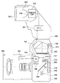
以下、本発明の一実施形態について、添付図面を参照して詳細に説明する。図1は本発明の一実施形態に係わる撮像装置(カメラシステム)の構成を示す図である。図1において、100はカメラ本体を、200はレンズを、300は照明装置(ストロボ)を示している。
Hereinafter, an embodiment of the present invention will be described in detail with reference to the accompanying drawings. FIG. 1 is a diagram showing a configuration of an imaging apparatus (camera system) according to an embodiment of the present invention. In FIG. 1,
まず、カメラ本体100とレンズ200の構成について説明する。101はカメラ100の各部を制御するマイクロコンピュータであるCPU(以下、カメラマイコン)である。102は赤外カットフィルタやローパスフィルタ等を含むCCD、CMOSセンサ等の撮影用の撮像素子であり、その撮像面上にレンズ200によって被写体の像が結像される。103はシャッターで、非撮影時には撮像素子102を遮光し、撮影時には開いて撮像素子102へ光線を導く。
First, the configuration of the
104はハーフミラーで非撮影時にレンズ200から入射する光の一部を反射しピント板105に結像させる。106は測光センサで、CCD、CMOSセンサ等の撮像素子を使用することにより光源判定処理、特定色検知処理や測光処理を行う。本実施形態では、測光センサ106としてR(赤),G(緑),B(青),IR(赤外光)画素からなるベイヤー配列のCMOSセンサを用いた場合について図4、図5を用いて後述する。
A
また、測光センサ106は、上記のように可視光域と赤外光域に感度を有し、ピント板105で拡散されてペンタプリズム107を通過した光のうち、光軸外の光線の一部が入射する位置に配置されている。107はペンタプリズムで、ピント板105に結像された被写体像を測光センサ106及びアイピース113に導く。108はCPU101に接続されているRAMやROM等のメモリである。
Further, the
109は焦点検出回路である。レンズ200から入射しハーフミラー104を通過した光線の一部がサブミラー110で反射され、焦点検出回路109内の焦点検出センサに導かれて焦点検出が行われる。111は測光センサ106の画像処理・演算用のCPU(以下ICPUと呼ぶ)である。112はICPU111に接続されているRAMやROM等のメモリである。113はユーザーが被写界を確認するためのアイピースである。なお、本実施形態では、測光センサ106専用のCPU111を用意しているが、カメラマイコン101を用いて測光センサ106の制御を行ってもよい。201はレンズ内のCPU(以下LPUと呼ぶ)で、被写体との距離情報等をカメラマイコン101に送る。
次に、ストロボ300の構成について説明する。301はストロボ300の各部の動作を制御するマイクロコンピュータSCPU(以下、ストロボマイコンと呼ぶ)である。302は光量制御装置で、電池電圧を昇圧して光源305を点灯させるための昇圧回路や、発光の開始及び停止を制御する電流制御回路等が含まれる。303はフレネルレンズなどのパネル等を備え、ストロボ300の照射角を変更するズーム光学系である。304は反射傘であり、光源の発光光束を集光し被写体に照射する。305はキセノン管や白色LEDなどの光源である。
Next, the configuration of the
次に、図2〜図3に示すフローチャートを参照して、カメラ本体100の動作について説明する。なお、ここでは、カメラ100の電源がオンされ、撮影スタンバイの状態にあるものとする。
Next, the operation of the
ステップS101でCPU101は、シャッタスイッチの第1ストローク(以下SW1と呼ぶ)がオンされたか否かを判別し、オンならステップS102に処理を進める。ステップS102でICPU111は測光センサ106を駆動させる。なお、測光センサ106の駆動の詳細は図3を参照して後述する。
In step S101, the
ステップS103で、CPU101、もしくはICPU111は、既知の位相差方式のAF(オートフォーカス)処理を行う。AF評価値を算出し、LPU201を介してレンズ200のフォーカスレンズを駆動させ、AF評価値が最大となるフォーカスレンズ位置にフォーカスレンズを移動させる。
In step S103, the
ステップS104でCPU101は、シャッタスイッチの第2ストローク(以下SW2と呼ぶ)がオンされたか否かを判別する。シャッタスイッチSW2がオフなら、CPU101はステップS105でシャッタスイッチSW1の状態を確認し、オンのままならステップS102に、オフになった場合はステップS101に、それぞれ処理を戻す。
In step S104, the
ステップS104でシャッタスイッチSW2がオンであれば、CPU101はステップS106で、ステップS102の測光センサ処理で得られた露出制御値に基づいて本撮像処理を実行する。
If the shutter switch SW2 is on in step S104, the
図3は、図2のステップS102における測光センサ処理の詳細を示すフローチャートである。ステップS201でICPU111は、測光センサの蓄積時間(Tv)を決定し、測光用蓄積処理を行う。ステップS202でICPU111は、撮像画像を複数のエリア(画素群)に分割し、エリア毎にR,G,B,IRの平均値(画像情報)を算出する(取得する)。なお、エリアの大きさは任意の大きさであり、平均値を算出せずに次のステップS203へ推移してもよい。
FIG. 3 is a flowchart showing details of the photometric sensor process in step S102 of FIG. In step S201, the
ステップS203でICPU111は、ステップS202で算出したエリア毎のR,G,B,IRの平均値に対して、既知のデフォーカス量補正処理を行う。デフォーカス量補正処理は、可視光域と赤外光域の出力差Pに応じて、オートフォーカスのピントずれを抑制する処理である。上記の出力差Pは、例えば以下の式によって算出される。
In step S203, the
P=(a1×R+b1×G+c1×B+d1×IR)/(a2×R+b2×G+c2×B+d2×IR) …(式1)
ここで、a1=1、b1=4、c1=1、d1=−10、a2=1、b2=1、c2=1、d2=1である。なお、デフォーカス量補正処理の詳細は図4から図7を参照して後述する。
P = (a1 * R + b1 * G + c1 * B + d1 * IR) / (a2 * R + b2 * G + c2 * B + d2 * IR) (Formula 1)
Here, a1 = 1, b1 = 4, c1 = 1, d1 = −10, a2 = 1, b2 = 1, c2 = 1, d2 = 1. Details of the defocus amount correction processing will be described later with reference to FIGS.
ステップS204でICPU111は、ステップS202で算出したエリア毎のR,G,B,IRの平均値に対して、以下の式により赤外光減算処理(赤外光成分の減算処理)を行う。
In step S204, the
R’=R−kr×IR …(式2)
G’=G−kg×IR …(式3)
B’=B−kb×IR …(式4)
ここで、kr=1.0,kg=0.3,kb=0.0とする。
R ′ = R−kr × IR (Formula 2)
G ′ = G−kg × IR (Formula 3)
B ′ = B−kb × IR (Formula 4)
Here, kr = 1.0, kg = 0.3, kb = 0.0.
上記演算では、R,G,Bの平均値からIRの平均値にゲインをかけたものを減算することで、色毎に赤外光減算処理を施したR’,G’,B’(可視光成分)を算出(生成)している。 In the above calculation, R ′, G ′, B ′ (visible) for which infrared light subtraction processing is performed for each color by subtracting the average value of IR multiplied by the gain from the average value of R, G, B. (Light component) is calculated (generated).
ステップS205でICPU111は、既知の光源判定処理を行う。光源判定処理結果をオートホワイトバランス処理等の画像処理に利用する。ステップS206でICPU111は、R’,G’,B’を用いて既知の特徴領域検出処理を行う。特徴領域検出処理とは、撮像画面内で人物の顔領域や特定色領域などの所定の条件を満たす特徴領域を検出する処理である。この特徴領域検出処理の結果もAF処理や測光処理などに用いられ、特徴領域に対して好適なAF処理や測光処理を行うことができる。
In step S205, the
ステップS207でICPU111は、ステップS202で算出したエリア毎のR,G,B、もしくはS204で算出したエリア毎のR’,G’,B’の積分値を任意の割合で加算した測光出力値Yを算出する。Yは例えば以下の式によって求められる。ここで、R,G,Bの積分値をそれぞれR_int,G_int,B_intとして、R’,G’,B’の積分値をそれぞれR’_int,G’_int,B’_intとする。
In step S207, the
Y=Ra×R_int+Ga×G_int+Ba×B_int …(式5)
Y=Ra×R’_int+Ga×G’_int+Ba×B’_int …(式6)
R画素、G画素、B画素の混合比Ra,Ga,Baに適当な値を入れることでエリア毎の輝度値Yが求められる。例えばRa=0.299、Ga=0.587、Ba=0.114とする。なお、測光演算処理の詳細は図4から図7を参照して後述する。
Y = Ra * R_int + Ga * G_int + Ba * B_int (Formula 5)
Y = Ra × R′_int + Ga × G′_int + Ba × B′_int (Formula 6)
The luminance value Y for each area can be obtained by entering appropriate values for the mixing ratios Ra, Ga, Ba of the R pixel, G pixel, and B pixel. For example, Ra = 0.299, Ga = 0.487, and Ba = 0.114. Details of the photometric calculation process will be described later with reference to FIGS.
エリア毎の測光出力値Yと後述する露出制御値用重み付け係数kとの加重平均値Ywを以下の式より算出する。 A weighted average value Yw of a photometric output value Y for each area and a weighting coefficient for exposure control value k described later is calculated from the following equation.
Yw=ΣYij×kij …(式7)
Yij、kijは、それぞれエリア毎の測光出力値Yと露出制御値用重み付け係数kを示している。iは横方向、jは縦方向のエリアの番号で、エリアの分割数に応じて合計する数が変わる。
Yw = ΣYij × kij (Expression 7)
Yij and kij indicate the photometric output value Y and the exposure control value weighting coefficient k for each area. i is the number of the area in the horizontal direction and j is the number of the area in the vertical direction, and the total number varies depending on the number of divided areas.
そしてICPU111は、加重平均値Yw、蓄積時間などから得られる被写体輝度に基づいて、本撮影時の露出制御値(シャッタ速度、絞り値、感度など)を算出する。なお、露出制御値(露光量)の決定方法は本実施形態とは直接関係がなく、また任意の方法を採用しうるためその詳細説明は省略する。
The
また、露出制御用重み付け係数kは、カメラ100の撮像モード、測光モードや撮影シーンなどに応じて各測光エリアの測光出力値の重み付けを変えるための係数である。例えば、測光モードが中央重点測光モードであれば、画像の中央付近の測光エリアに対する重み付け係数を画像の周辺付近に対する重み付け係数よりも大きくする。また、特徴領域検出機能を有する場合、特徴領域検出機能を用いる撮像モードでは特徴領域に対応する測光エリアに対する重み付け係数を他の測光エリアに対する重み付け係数よりも大きくする。
The exposure control weighting coefficient k is a coefficient for changing the weighting of the photometric output value of each photometric area in accordance with the imaging mode, photometric mode, shooting scene, etc. of the
また、被写界の状況に応じてどのような撮影シーンかを自動判別するシーン判別機能を有する場合、判別されたシーンに最適な重み付け係数をそれぞれの測光エリアに対して設定する。露出制御用重み付け係数kは本実施形態とは直接関係がないため、これ以上の詳細説明は省略する。 In addition, when the camera has a scene discrimination function for automatically discriminating what kind of shooting scene is in accordance with the situation of the object scene, an optimum weighting coefficient for the discriminated scene is set for each photometric area. Since the exposure control weighting coefficient k is not directly related to the present embodiment, further detailed description thereof is omitted.
次に、図4の測光センサ106の画素配列を示した図、図5のカラーフィルタの光学特性を示した図、図6の撮影用の撮像素子102の分光特性を示した図、図7の光源の分光特性を示した図を用いてデフォーカス量補正、光源判定、特徴色検出、測光演算処理について説明する。
Next, FIG. 4 is a diagram showing the pixel arrangement of the
本実施形態では、図4のようにR(赤),G(緑),B(青),IR(赤外光)の画素がM×N個(縦M画素、横N画素)ベイヤー状に並んだCMOSセンサを使用した例について説明する。 In this embodiment, as shown in FIG. 4, R (red), G (green), B (blue), and IR (infrared light) pixels are M × N (vertical M pixels, horizontal N pixels) Bayer shape. An example in which side-by-side CMOS sensors are used will be described.
図5(a)は測光センサ106のR,G,B,IR画素の分光特性を示している。図5(b)は図5(a)の出力に対して、赤外光減算処理を施したR’,G’,B’の分光特性を示す。図6は撮影用の撮像素子102の分光特性を示している。なお、赤外カットフィルタは680nmの例である。図5(b)、図6から、2つのセンサの分光特性の赤外光域の差を抑制できていることが確認できる。
FIG. 5A shows the spectral characteristics of the R, G, B, and IR pixels of the
しかし、赤外光減算処理(式2)〜(式4)の演算では、乗算、差分演算による演算誤差が発生することがある。一般的に、演算量削減や回路規模削減のため、整数型を用いて演算を行う。kr、kg、kbの少数第1位を表すためには、kr、kg、kbを10倍した値を乗算した後、10で除算することで表現される。ステップS202で算出した色毎の平均値がR=100、G=200、B=50、IR=40のとき、ステップS204での赤外光減算処理結果は(式2)〜(式4)よりR’=60、G’=188、B’=46となる。ステップS202で算出した色毎の平均値が上記値の10%のR=10、G=20、B=5、IR=4のとき、ステップS204での赤外光減算処理結果は(式2)〜(式4)よりR’=6、G’=19、B’=5となる。 However, in the calculation of the infrared light subtraction processing (Equation 2) to (Equation 4), calculation errors due to multiplication and difference calculation may occur. In general, computation is performed using an integer type in order to reduce the amount of computation and the circuit scale. In order to represent the first decimal place of kr, kg, kb, it is expressed by multiplying kr, kg, kb by 10 and then dividing by 10. When the average value for each color calculated in step S202 is R = 100, G = 200, B = 50, and IR = 40, the infrared light subtraction processing results in step S204 are obtained from (Expression 2) to (Expression 4). R ′ = 60, G ′ = 188, and B ′ = 46. When the average value for each color calculated in step S202 is 10% of the above values, R = 10, G = 20, B = 5, IR = 4, the result of the infrared light subtraction process in step S204 is (Expression 2). From (Expression 4), R ′ = 6, G ′ = 19, and B ′ = 5.
上記のように、色毎の平均値R,G,Bの比率が同じであっても、演算後のR’,G’,B’の比率が変わることがある。上記比率の変化はR,G,Bが小さい場合に発生し、演算誤差の原因となる。以上より、赤外光減算処理が必要ない処理では、色毎の平均値R,G,Bを用いることが望ましい。 As described above, even if the ratio of the average values R, G, and B for each color is the same, the ratio of R ′, G ′, and B ′ after the calculation may change. The change in the ratio occurs when R, G, and B are small, and causes a calculation error. As described above, it is desirable to use the average values R, G, and B for each color in the process that does not require the infrared light subtraction process.
ステップS203のデフォーカス量補正処理では、可視光域と赤外光域の比率を検知できればよい。そのため、色毎の平均値R,G,Bを用いて(式1)より出力差Pを算出する。ステップS205の光源判定処理とステップS206の特徴領域検出処理では、図7(a)のように赤外光域の光が少ないLEDなどの人工光源下と、図7(b)のような赤外光域を多く含む太陽光下(晴天時)での色相ずれを抑制するため、ステップS204で赤外光減算処理を行ったR’,G’,B’を用いて処理を行う。 In the defocus amount correction process in step S203, it is only necessary to detect the ratio between the visible light region and the infrared light region. Therefore, the output difference P is calculated from (Equation 1) using the average values R, G, and B for each color. In the light source determination processing in step S205 and the feature region detection processing in step S206, an artificial light source such as an LED with little light in the infrared light region as shown in FIG. 7A and an infrared light as shown in FIG. In order to suppress a hue shift under sunlight including a lot of light areas (at the time of fine weather), processing is performed using R ′, G ′, and B ′ that have been subjected to infrared light subtraction processing in step S204.
ステップS207の測光演算処理では、測光センサ106と撮影用の撮像素子102の分光感度差を抑制するため、ステップS204で赤外光減算処理を行ったR’,G’,B’を用いて(式6)より測光出力値Yを算出する。
In the photometric calculation process in step S207, R ′, G ′, and B ′ subjected to the infrared light subtraction process in step S204 are used in order to suppress the spectral sensitivity difference between the
しかし、ステップS202で算出した色毎の平均値R,G,Bの値が小さいときには、上述した演算誤差が発生する。そのため、色毎の平均値R,G,Bを用いて(式5)より測光出力値Yを算出してもよい。このとき、測光センサ106と撮影用の撮像素子102の分光感度差だけ測光演算結果にずれが生じるが、上述した演算誤差は抑制できる。
However, when the average values R, G, and B for each color calculated in step S202 are small, the calculation error described above occurs. Therefore, the photometric output value Y may be calculated from (Equation 5) using the average values R, G, and B for each color. At this time, a shift occurs in the photometric calculation result by the difference in spectral sensitivity between the
また、ステップS202で算出した色毎の平均値R,G,Bの出力に応じて、測光出力値Yを算出する式を切り替えてもよい。例えば、色毎の平均値R,G,Bがある閾値よりも大きい場合には(式6)、小さい場合には(式5)を演算に用いる。 Further, the equation for calculating the photometric output value Y may be switched according to the output of the average values R, G, and B for each color calculated in step S202. For example, when the average values R, G, and B for each color are larger than a certain threshold (Equation 6), when it is smaller, (Equation 5) is used for the calculation.
次に、図8から図11を用いて赤外光減算処理を用いた特定色検知処理について説明する。 Next, the specific color detection process using the infrared light subtraction process will be described with reference to FIGS.
特定色の抽出では、まず撮影環境における光源判定処理を行い、オートホワイトバランス制御を行う。これは、画面内の画像から得られる輝度情報や色情報により光源の色温度を推定し、白い被写体を撮影した時に、各R,G,Bの画素出力が同一のレベルになるように、R,G,Bのゲインを調整する既知の技術である。 In extraction of a specific color, first, light source determination processing in a shooting environment is performed, and auto white balance control is performed. This is because the color temperature of the light source is estimated from the luminance information and color information obtained from the image in the screen, and when a white subject is photographed, the R, G, B pixel outputs are at the same level. , G and B are known techniques for adjusting the gain.
図8は測光センサ106のR,G,B画素出力(分光特性:図4(a))にゲイン調整を行ったものを、縦軸R/G、横軸B/Gの色差平面上に簡略化してグラフとして示したものである。 FIG. 8 is a simplified version of the R, G, B pixel output of the photometric sensor 106 (spectral characteristics: FIG. 4A) on the color difference plane of the vertical axis R / G and the horizontal axis B / G. This is shown as a graph.
ホワイトバランス制御した画像データより、エリア毎に色成分毎の平均値をB/G値とR/G値の色差信号とする。色差信号の二次元平面上(色空間)において、特定色がプロットされる範囲が決まっているため、色空間であらかじめサンプリングした特定色の情報から特定色枠を定め、エリア毎に色空間上で特定色枠内に入るか否かを判定する。 From the image data subjected to white balance control, an average value for each color component is set as a color difference signal of B / G value and R / G value for each area. Since the range in which the specific color is plotted on the two-dimensional plane (color space) of the color difference signal is determined, a specific color frame is determined from information on the specific color sampled in advance in the color space, It is determined whether or not it falls within a specific color frame.
例えば、特定色として肌色を抽出する場合に、肌色は図8に示す色空間において左上(第2象限)の範囲に存在することがわかっているため、左上の範囲に肌検出枠400を設定し、肌色の抽出を行う。
For example, when the skin color is extracted as the specific color, since it is known that the skin color exists in the upper left (second quadrant) range in the color space shown in FIG. 8, the
図9(a)は肌色の分光特性、図9(b)は赤外線反射材を含む黒色繊維の分光特性を示している。図10は図7(a)のLED光源下と図7(b)の太陽光下(晴天時)の場合に、肌色座標410と赤外線反射材を含む黒色繊維座標420が図8の色差平面でどこにプロットされるかを示している。
FIG. 9A shows the spectral characteristics of skin color, and FIG. 9B shows the spectral characteristics of black fibers including an infrared reflecting material. FIG. 10 shows the
図10(a)のLED光源下(分光特性:図7(a))では赤外光域の光が少ないため、肌色410は肌検出枠400内にプロットされる。赤外線反射材を含む黒色繊維420は無彩色である色差平面中央にプロットされる。
Under the LED light source of FIG. 10A (spectral characteristics: FIG. 7A), the
しかし、図10(b)の太陽光下(晴天時)(分光特性:図7(b))では、LED光源下(分光特性:図7(a))に対して赤外光域の光が大きいため、図10(a)に対して相対的にR/Gが大きくなり、B/Gが小さくなる。つまり、肌色410が肌検出枠400外にプロットされることがある。また、赤外線反射材を含む黒色繊維420が肌検出枠400内にプロットされ、肌色と誤検知することがある。また、他の赤外線を多く反射する物質も、光源によって色差平面でプロットされる位置がずれるため、色の誤検知が発生することがある。
However, in the sunlight of FIG. 10B (at the time of fine weather) (spectral characteristics: FIG. 7B), the light in the infrared region is lower than that of the LED light source (spectral characteristics: FIG. 7A). Since it is large, R / G is relatively large and B / G is small relative to FIG. That is, the
図11は、上述した赤外光減算処理を行ったR’,G’,B’ (分光特性:図5(b))にゲイン調整を行った後の色差平面において、図7(a)のLED光源と図7(b)の太陽光下(晴天時)の場合に肌色410と赤外線反射材を含む黒色繊維420が色空間のどこにプロットされるかを示している。
FIG. 11 shows a color difference plane after gain adjustment is performed on R ′, G ′, B ′ (spectral characteristics: FIG. 5B) subjected to the above-described infrared light subtraction process. 7 shows where the
図11(a)のLED光源下(分光特性:図7(a))、図11(b)の太陽光下(晴天時)(分光特性:図7(b))共に、肌色410は肌検出枠400内にプロットされる。赤外線反射材を含む黒色繊維420は無彩色である色空間の中央にプロットされる。赤外光減算処理により色毎に赤外光域を減算することで、光源の赤外光の有無にかかわらず、色差平面におけるプロット位置のずれを抑制できる。
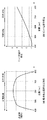
次に、図12を用いてデフォーカス量補正処理について説明する。焦点検出回路109では、公知の位相差による焦点検出方法によりデフォーカス量defの演算を行う。ここでは、レンズ200を透過した光束をビームスプリッタで2系統に分割して、分割した各光束の光軸を互いにずらし、2つの結像レンズで焦点検出センサに結像させ、形成された2つの画像間の位相差に基づいてデフォーカス量defを計算する。そして、そのデフォーカス量に応じてレンズ200を駆動し合焦させる。
Next, the defocus amount correction process will be described with reference to FIG. The
図12(a)は焦点検出回路109の分光特性を示している。低輝度下で合焦動作ができない場合に、カメラ側の発光ダイオードから近赤外(700nm程度)の光を被写体に照射するので、図6の撮影用の撮像素子102の分光特性よりも100nm程度長波長領域まで感度を有するようにしている。図12(b)は光の波長に対するレンズ200の色収差による相対的なピント位置の変位を示す図である。
FIG. 12A shows the spectral characteristics of the
被写体を照明する光源が赤外光域成分の少ないLED(分光特性:図7(a))の場合は、可視光域の500nm付近が光源の分光分布の中心であるので、レンズの焦点距離が短くなる方向である。一方、被写体を照明する光源が赤外光域成分を多く有する太陽光下(分光特性:図7(b))の場合は、レンズの焦点距離が伸びる方向である。そのため、同じ位置に被写体があったとしても、結果として撮像面側でピントがずれてしまうと言う問題が生じる。 When the light source for illuminating the subject is an LED (spectral characteristic: FIG. 7A) having a small infrared light component, the vicinity of 500 nm in the visible light region is the center of the spectral distribution of the light source. It is a direction to shorten. On the other hand, when the light source that illuminates the subject is in sunlight (spectral characteristics: FIG. 7B) having many infrared light region components, the focal length of the lens increases. Therefore, even if there is a subject at the same position, there arises a problem that as a result, the image plane is out of focus.
測光センサ106(分光特性:図5(a))では、複数の分光感度を検知することができる。このセンサの出力を(式1)に代入すると、被写体を照明する光源が短波長成分を多く含む程、出力差Pは正の値となる。また、被写体を照明する光源が長波長成分を多く含む程、出力差Pは負の値となる。 The photometric sensor 106 (spectral characteristics: FIG. 5A) can detect a plurality of spectral sensitivities. When the output of this sensor is substituted into (Equation 1), the output difference P becomes a positive value as the light source that illuminates the subject contains more short wavelength components. Further, as the light source that illuminates the subject includes more long wavelength components, the output difference P becomes a negative value.
出力差Pを用いて、デフォーカス量補正値(補正量)を算出する。つまりデフォーカス量をdef、ピント補正係数をkとすると、 最終デフォーカス量を(式8)より算出する。 A defocus amount correction value (correction amount) is calculated using the output difference P. That is, if the defocus amount is def and the focus correction coefficient is k, the final defocus amount is calculated from (Equation 8).
最終デフォーカス量=k×P+def …(式8)
この演算により、ピント方向の変位を補正することが可能となる。
Final defocus amount = k × P + def (Expression 8)
By this calculation, the displacement in the focus direction can be corrected.
なお、デフォーカス量補正値は、出力差Pの値に応じたテーブルデータを作り、このデータを参照して求めてもよい。また、(式1)を算出する場合、赤外光減算処理を行ったR’,G’,B’とIRを用いて演算することも可能であるが、上述したように演算誤差により精度が落ちる。そのため、R,G,B,IRを用いて演算することが望ましい。また、本実施形態では、デフォーカス量補正処理を行ってピント方向の変位を補正しているが、レンズ駆動量など他のピント合わせに係わる制御値(焦点制御値)を補正対象とした焦点制御値補正処理を行ってもよい。 The defocus amount correction value may be obtained by making table data corresponding to the value of the output difference P and referring to this data. In addition, when calculating (Equation 1), it is possible to calculate using R ′, G ′, B ′ and IR that have been subjected to infrared light subtraction processing. drop down. Therefore, it is desirable to calculate using R, G, B, and IR. In this embodiment, the defocus amount correction process is performed to correct the displacement in the focus direction. However, the focus control is performed using a control value (focus control value) related to another focus, such as a lens drive amount, as a correction target. Value correction processing may be performed.
これらの処理によりデフォーカス量補正、光源判定、特徴色検知、測光演算処理などを良好に行うことができる。なお、測光演算処理や顔領域検出処理は、夜景撮影シーンなどのR,G,Bの信号量が小さい場合に赤外光減算処理を行うと、R,G,Bの信号量が小さくなりすぎて測光演算処理や顔領域検出処理が精度よく行えないことがある。そのため、赤外光減算処理を行わずに測光演算処理や顔領域検出処理を行う構成でもよい。 With these processes, defocus amount correction, light source determination, characteristic color detection, photometric calculation processing, and the like can be performed satisfactorily. In the photometric calculation process and the face area detection process, if the R, G, B signal amount is small, such as in a night scene, the infrared light subtraction process causes the R, G, B signal amount to be too small. Therefore, the photometric calculation process and the face area detection process may not be performed accurately. Therefore, a configuration in which photometric calculation processing and face area detection processing are performed without performing infrared light subtraction processing may be employed.
以上、本発明の好ましい実施形態について説明したが、本発明はこれらの実施形態に限定されず、その要旨の範囲内で種々の変形及び変更が可能である。 As mentioned above, although preferable embodiment of this invention was described, this invention is not limited to these embodiment, A various deformation | transformation and change are possible within the range of the summary.
(その他の実施形態)
また、本発明は、以下の処理を実行することによっても実現される。即ち、上述した実施形態の機能を実現するソフトウェア(プログラム)を、ネットワーク又は各種記憶媒体を介してシステム或いは装置に供給し、そのシステム或いは装置のコンピュータ(またはCPUやMPU等)がプログラムを読み出して実行する処理である。
(Other embodiments)
The present invention can also be realized by executing the following processing. That is, software (program) that realizes the functions of the above-described embodiments is supplied to a system or apparatus via a network or various storage media, and a computer (or CPU, MPU, or the like) of the system or apparatus reads the program. It is a process to be executed.
100:カメラ本体、101:カメラマイコン、102:撮像素子、106:測光センサ、109:焦点検出回路、200:レンズ、300:照明装置(ストロボ) DESCRIPTION OF SYMBOLS 100: Camera main body, 101: Camera microcomputer, 102: Image sensor, 106: Photometric sensor, 109: Focus detection circuit, 200: Lens, 300: Illuminating device (strobe)
Claims (14)
前記測光センサを複数の画素群に分け、該複数の画素群ごとに赤外光域の画像情報と可視光域の画像情報を取得する取得手段と、
前記複数の画素群ごとの画像情報から前記赤外光域の画像情報に基づく赤外光成分を減算した可視光成分を生成する減算手段と、
前記取得手段により取得された、前記赤外光域の画像情報と可視光域の画像情報を用いて第1の処理を行う第1の処理手段と、
前記減算手段により生成された前記可視光成分を用いて、第2の処理を行う第2の処理手段と、
を備えることを特徴とする撮像装置。 A photometric sensor having a plurality of pixels having sensitivity in the infrared light region and the visible light region;
The photometric sensor is divided into a plurality of pixel groups, and acquisition means for acquiring image information in the infrared light region and image information in the visible light region for each of the plurality of pixel groups;
Subtracting means for generating a visible light component obtained by subtracting an infrared light component based on image information in the infrared light region from image information for each of the plurality of pixel groups;
First processing means for performing a first process using the image information in the infrared light range and the image information in the visible light range acquired by the acquisition means;
Second processing means for performing second processing using the visible light component generated by the subtracting means;
An imaging apparatus comprising:
前記測光センサを複数の画素群に分け、該複数の画素群ごとに赤外光域の画像情報と可視光域の画像情報を取得する取得工程と、
前記複数の画素群ごとの画像情報から前記赤外光域の画像情報に基づく赤外光成分を減算した可視光成分を生成する減算工程と、
前記取得工程により取得された、前記赤外光域の画像情報と可視光域の画像情報を用いて第1の処理を行う第1の処理工程と、
前記減算工程により生成された前記可視光成分を用いて、第2の処理を行う第2の処理工程と、
を有することを特徴とする撮像装置の制御方法。 A method for controlling an imaging device including a photometric sensor having a plurality of pixels having sensitivity in an infrared light region and a visible light region,
The step of dividing the photometric sensor into a plurality of pixel groups, and acquiring the image information in the infrared light region and the image information in the visible light region for each of the plurality of pixel groups;
A subtracting step for generating a visible light component obtained by subtracting an infrared light component based on the image information in the infrared light region from the image information for each of the plurality of pixel groups;
A first processing step of performing a first processing using the image information in the infrared light region and the image information in the visible light region acquired by the acquisition step;
A second processing step of performing a second processing using the visible light component generated by the subtraction step;
A method for controlling an imaging apparatus, comprising:
Priority Applications (2)
| Application Number | Priority Date | Filing Date | Title |
|---|---|---|---|
| JP2014123809A JP6336337B2 (en) | 2014-06-16 | 2014-06-16 | Imaging apparatus, control method therefor, program, and storage medium |
| US14/739,904 US10063795B2 (en) | 2014-06-16 | 2015-06-15 | Image capturing apparatus, method for controlling the same, and storage medium |
Applications Claiming Priority (1)
| Application Number | Priority Date | Filing Date | Title |
|---|---|---|---|
| JP2014123809A JP6336337B2 (en) | 2014-06-16 | 2014-06-16 | Imaging apparatus, control method therefor, program, and storage medium |
Publications (3)
| Publication Number | Publication Date |
|---|---|
| JP2016004134A JP2016004134A (en) | 2016-01-12 |
| JP2016004134A5 JP2016004134A5 (en) | 2017-07-20 |
| JP6336337B2 true JP6336337B2 (en) | 2018-06-06 |
Family
ID=55223451
Family Applications (1)
| Application Number | Title | Priority Date | Filing Date |
|---|---|---|---|
| JP2014123809A Active JP6336337B2 (en) | 2014-06-16 | 2014-06-16 | Imaging apparatus, control method therefor, program, and storage medium |
Country Status (1)
| Country | Link |
|---|---|
| JP (1) | JP6336337B2 (en) |
Cited By (1)
| Publication number | Priority date | Publication date | Assignee | Title |
|---|---|---|---|---|
| JP7337611B2 (en) | 2019-09-06 | 2023-09-04 | 株式会社東芝 | Gripping device, cargo handling device, and control device |
Families Citing this family (3)
| Publication number | Priority date | Publication date | Assignee | Title |
|---|---|---|---|---|
| US9188275B2 (en) | 2010-07-30 | 2015-11-17 | Ergotron, Inc. | Edge mount positioning apparatus, system, and method |
| JP7113283B2 (en) | 2017-05-26 | 2022-08-05 | パナソニックIpマネジメント株式会社 | Imaging device, imaging system, vehicle driving control system, and image processing device |
| TW202303511A (en) * | 2021-01-29 | 2023-01-16 | 日商索尼半導體解決方案公司 | Image processing device, image processing method, and image processing program |
Family Cites Families (7)
| Publication number | Priority date | Publication date | Assignee | Title |
|---|---|---|---|---|
| JP2006033483A (en) * | 2004-07-16 | 2006-02-02 | Aisin Seiki Co Ltd | Color imaging apparatus |
| JP2006065076A (en) * | 2004-08-27 | 2006-03-09 | Canon Inc | Imaging device, control method for imaging device, control program, and storage medium |
| JP2007139848A (en) * | 2005-11-15 | 2007-06-07 | Canon Inc | Focus detector and imaging apparatus |
| US7821552B2 (en) * | 2005-12-27 | 2010-10-26 | Sanyo Electric Co., Ltd. | Imaging apparatus provided with imaging device having sensitivity in visible and infrared regions |
| JP4420917B2 (en) * | 2005-12-27 | 2010-02-24 | 三洋電機株式会社 | Imaging device |
| JP5794665B2 (en) * | 2011-02-16 | 2015-10-14 | キヤノン株式会社 | Imaging device |
| JP2013121132A (en) * | 2011-12-08 | 2013-06-17 | Samsung Yokohama Research Institute Co Ltd | Imaging apparatus and imaging method |
-
2014
- 2014-06-16 JP JP2014123809A patent/JP6336337B2/en active Active
Cited By (1)
| Publication number | Priority date | Publication date | Assignee | Title |
|---|---|---|---|---|
| JP7337611B2 (en) | 2019-09-06 | 2023-09-04 | 株式会社東芝 | Gripping device, cargo handling device, and control device |
Also Published As
| Publication number | Publication date |
|---|---|
| JP2016004134A (en) | 2016-01-12 |
Similar Documents
| Publication | Publication Date | Title |
|---|---|---|
| US7852381B2 (en) | Image signal processor with white balance calculation based upon selected prediction area | |
| US10063795B2 (en) | Image capturing apparatus, method for controlling the same, and storage medium | |
| US8294785B2 (en) | Method for adjusting photosensitiveness of digital camera | |
| US11418730B2 (en) | Use of IR pre-flash for RGB camera's automatic algorithms | |
| US8831414B2 (en) | Imaging apparatus, light emitting device, imaging system, and control method | |
| JP6467190B2 (en) | EXPOSURE CONTROL DEVICE AND ITS CONTROL METHOD, IMAGING DEVICE, PROGRAM, AND STORAGE MEDIUM | |
| JP6336337B2 (en) | Imaging apparatus, control method therefor, program, and storage medium | |
| JP2009059326A (en) | Imaging apparatus | |
| JP2009004895A (en) | Imaging apparatus, image processor, and program | |
| US11275289B2 (en) | Image pickup apparatus that controls flash emission amount at photographing and control method therefor | |
| US9921454B2 (en) | Imaging apparatus capable of generating an image with a weight of a signal corresponding to each type of spectral sensitivity characteristics and method of controlling the apparatus | |
| US20200036877A1 (en) | Use of ir pre-flash for rgb camera's automatic algorithms | |
| JP5794665B2 (en) | Imaging device | |
| US9906705B2 (en) | Image pickup apparatus | |
| US8630535B2 (en) | Light emission control device and light emission control method | |
| US11115603B2 (en) | Image pickup apparatus that reduces time required for light control processing and method of controlling same | |
| JP2016004133A (en) | Imaging device and control method of the same, program, and memory medium | |
| JP6660036B2 (en) | Focus detection device and imaging device | |
| US10873707B2 (en) | Image pickup apparatus and method, for ensuring correct color temperature based on first or second preliminary light emission of a flash device | |
| JP6388391B2 (en) | Backlight discrimination device, control method thereof, control program, and imaging device | |
| JP2019053315A (en) | Focus adjustment device and imaging device | |
| JP2013040994A (en) | Imaging apparatus | |
| JP2015200714A (en) | Focus adjustment device and imaging device | |
| JPH09203926A (en) | Camera | |
| JP2008096517A (en) | Exposure arithmetic operation device, exposure arithmetic operation method and camera |
Legal Events
| Date | Code | Title | Description |
|---|---|---|---|
| A521 | Request for written amendment filed |
Free format text: JAPANESE INTERMEDIATE CODE: A523 Effective date: 20170608 |
|
| A621 | Written request for application examination |
Free format text: JAPANESE INTERMEDIATE CODE: A621 Effective date: 20170608 |
|
| A977 | Report on retrieval |
Free format text: JAPANESE INTERMEDIATE CODE: A971007 Effective date: 20180309 |
|
| TRDD | Decision of grant or rejection written | ||
| A01 | Written decision to grant a patent or to grant a registration (utility model) |
Free format text: JAPANESE INTERMEDIATE CODE: A01 Effective date: 20180406 |
|
| A61 | First payment of annual fees (during grant procedure) |
Free format text: JAPANESE INTERMEDIATE CODE: A61 Effective date: 20180502 |
|
| R151 | Written notification of patent or utility model registration |
Ref document number: 6336337 Country of ref document: JP Free format text: JAPANESE INTERMEDIATE CODE: R151 |