JP5467117B2 - Liquid ejection apparatus, liquid ejection head cleaning apparatus, and ink jet recording apparatus - Google Patents
Liquid ejection apparatus, liquid ejection head cleaning apparatus, and ink jet recording apparatus Download PDFInfo
- Publication number
- JP5467117B2 JP5467117B2 JP2012037836A JP2012037836A JP5467117B2 JP 5467117 B2 JP5467117 B2 JP 5467117B2 JP 2012037836 A JP2012037836 A JP 2012037836A JP 2012037836 A JP2012037836 A JP 2012037836A JP 5467117 B2 JP5467117 B2 JP 5467117B2
- Authority
- JP
- Japan
- Prior art keywords
- wiping
- liquid ejection
- wiping member
- head
- liquid
- Prior art date
- Legal status (The legal status is an assumption and is not a legal conclusion. Google has not performed a legal analysis and makes no representation as to the accuracy of the status listed.)
- Expired - Fee Related
Links
Images


Classifications
-
- B—PERFORMING OPERATIONS; TRANSPORTING
- B41—PRINTING; LINING MACHINES; TYPEWRITERS; STAMPS
- B41J—TYPEWRITERS; SELECTIVE PRINTING MECHANISMS, i.e. MECHANISMS PRINTING OTHERWISE THAN FROM A FORME; CORRECTION OF TYPOGRAPHICAL ERRORS
- B41J2/00—Typewriters or selective printing mechanisms characterised by the printing or marking process for which they are designed
- B41J2/005—Typewriters or selective printing mechanisms characterised by the printing or marking process for which they are designed characterised by bringing liquid or particles selectively into contact with a printing material
- B41J2/01—Ink jet
- B41J2/135—Nozzles
- B41J2/165—Preventing or detecting of nozzle clogging, e.g. cleaning, capping or moistening for nozzles
- B41J2/16517—Cleaning of print head nozzles
- B41J2/16535—Cleaning of print head nozzles using wiping constructions
-
- B—PERFORMING OPERATIONS; TRANSPORTING
- B41—PRINTING; LINING MACHINES; TYPEWRITERS; STAMPS
- B41J—TYPEWRITERS; SELECTIVE PRINTING MECHANISMS, i.e. MECHANISMS PRINTING OTHERWISE THAN FROM A FORME; CORRECTION OF TYPOGRAPHICAL ERRORS
- B41J2/00—Typewriters or selective printing mechanisms characterised by the printing or marking process for which they are designed
- B41J2/005—Typewriters or selective printing mechanisms characterised by the printing or marking process for which they are designed characterised by bringing liquid or particles selectively into contact with a printing material
- B41J2/01—Ink jet
- B41J2/135—Nozzles
- B41J2/165—Preventing or detecting of nozzle clogging, e.g. cleaning, capping or moistening for nozzles
- B41J2/16579—Detection means therefor, e.g. for nozzle clogging
-
- B—PERFORMING OPERATIONS; TRANSPORTING
- B41—PRINTING; LINING MACHINES; TYPEWRITERS; STAMPS
- B41J—TYPEWRITERS; SELECTIVE PRINTING MECHANISMS, i.e. MECHANISMS PRINTING OTHERWISE THAN FROM A FORME; CORRECTION OF TYPOGRAPHICAL ERRORS
- B41J2/00—Typewriters or selective printing mechanisms characterised by the printing or marking process for which they are designed
- B41J2/005—Typewriters or selective printing mechanisms characterised by the printing or marking process for which they are designed characterised by bringing liquid or particles selectively into contact with a printing material
- B41J2/01—Ink jet
- B41J2/21—Ink jet for multi-colour printing
- B41J2/2132—Print quality control characterised by dot disposition, e.g. for reducing white stripes or banding
- B41J2/2146—Print quality control characterised by dot disposition, e.g. for reducing white stripes or banding for line print heads
-
- B—PERFORMING OPERATIONS; TRANSPORTING
- B41—PRINTING; LINING MACHINES; TYPEWRITERS; STAMPS
- B41J—TYPEWRITERS; SELECTIVE PRINTING MECHANISMS, i.e. MECHANISMS PRINTING OTHERWISE THAN FROM A FORME; CORRECTION OF TYPOGRAPHICAL ERRORS
- B41J2/00—Typewriters or selective printing mechanisms characterised by the printing or marking process for which they are designed
- B41J2/005—Typewriters or selective printing mechanisms characterised by the printing or marking process for which they are designed characterised by bringing liquid or particles selectively into contact with a printing material
- B41J2/01—Ink jet
- B41J2/135—Nozzles
- B41J2/165—Preventing or detecting of nozzle clogging, e.g. cleaning, capping or moistening for nozzles
- B41J2/16517—Cleaning of print head nozzles
- B41J2/16535—Cleaning of print head nozzles using wiping constructions
- B41J2002/1655—Cleaning of print head nozzles using wiping constructions with wiping surface parallel with nozzle plate and mounted on reels, e.g. cleaning ribbon cassettes
Description
本発明は液体吐出装置、液体吐出ヘッドの清掃装置及びインクジェット記録装置に係り、特に長尺状の払拭部材を用いて液体吐出ヘッドの液体吐出面を払拭するヘッドクリーニング技術及びこれを適用した液体吐出装置及びインクジェット記録装置に関する。 The present invention relates to a liquid ejection apparatus, a liquid ejection head cleaning apparatus, and an ink jet recording apparatus, and more particularly, a head cleaning technique for wiping a liquid ejection surface of a liquid ejection head using a long wiping member, and a liquid ejection using the same. The present invention relates to an apparatus and an inkjet recording apparatus.
インクジェット記録装置では、使用に伴い液体吐出ヘッドの液体吐出面(ノズルが形成されているノズル面)にインクの残渣や紙粉などの異物が付着する。ノズルやその周囲に異物が付着していると、ノズルからの吐出液滴が影響を受けて吐出方向にバラツキが生じ、記録媒体上の所定の位置にインク液滴を着弾させることが困難となる。その結果、出力画像品質が低下する。そのためインクジェット記録装置では、ノズル面に付着した異物を定期的に又は適宜のタイミングでワイピング等によって除去するメンテナンス動作が行われる(特許文献1、2参照)。 In the ink jet recording apparatus, foreign matter such as ink residue or paper dust adheres to the liquid discharge surface (nozzle surface on which the nozzles are formed) of the liquid discharge head as it is used. If foreign matter adheres to the nozzle and its surroundings, the droplets ejected from the nozzle are affected, causing variations in the ejection direction, making it difficult to land the ink droplets at a predetermined position on the recording medium. . As a result, the output image quality is degraded. For this reason, in the ink jet recording apparatus, a maintenance operation is performed to remove foreign matter adhering to the nozzle surface periodically or at an appropriate timing by wiping or the like (see Patent Documents 1 and 2).
特許文献1には、ロール状に巻かれた長尺のワイピングシート(払拭部材)に対して洗浄液を供給する洗浄液供給手段と、ワイピングシートをヘッドのノズル面に押圧する押圧手段とを備えるワイピングユニットが開示されている。ワイピングシートは、シート供給ユニットの操出リールから送り出され、押圧ローラを経由して巻取リールに巻き取られる。このようにワイピングシートを一定方向に搬送しながら、押圧ローラをノズル面に沿って移動させることにより、ワイピングシートをノズル面に押圧、摺動させてノズル面の払拭が行われる。また、特許文献1では、洗浄液を含浸させた状態のワイピングシートをノズル面に押し当てる第1の払拭動作と、乾燥状態のワイピングシートをノズル面に押し当てる第2の払拭動作とを順次実行する制御手段を備えることを提案している。 Patent Document 1 discloses a wiping unit including a cleaning liquid supply unit that supplies a cleaning liquid to a long wiping sheet (wiping member) wound in a roll shape, and a pressing unit that presses the wiping sheet against a nozzle surface of a head. Is disclosed. The wiping sheet is sent out from the operation reel of the sheet supply unit, and taken up on the take-up reel via the pressing roller. In this way, by moving the pressing roller along the nozzle surface while conveying the wiping sheet in a certain direction, the nozzle surface is wiped by pressing and sliding the wiping sheet against the nozzle surface. Further, in Patent Document 1, a first wiping operation for pressing a wiping sheet impregnated with a cleaning liquid against a nozzle surface and a second wiping operation for pressing a dry wiping sheet against a nozzle surface are sequentially executed. Propose to provide control means.
特許文献2では、布やフィルムなどシート状の柔軟な清浄手段をヘッド下面に対応するように支持する支持手段と、この支持手段に支持された清浄手段を下方から押し付ける押し付け手段とを備えるインクジェットヘッドの清浄装置が開示されている。
In
特許文献1では、ワイピングシートをノズル面に押圧するための押圧ローラは、軸部の外周にゴム等の弾性体を装着した弾性ローラで構成されている(特許文献1の段落0056)。この弾性ローラ(押圧ローラ)がノズル面の直下部を横切るときに、ワイピングシートと押圧ローラが下方に圧縮されて、その弾性復元力によりワイピングシートがノズル面に押し付けられる構成となっている。しかし、引用文献1の装置は押し付け力を管理する手段を有していない。 In Patent Document 1, the pressing roller for pressing the wiping sheet against the nozzle surface is composed of an elastic roller in which an elastic body such as rubber is mounted on the outer periphery of the shaft portion (paragraph 0056 of Patent Document 1). When this elastic roller (pressing roller) crosses immediately below the nozzle surface, the wiping sheet and the pressing roller are compressed downward, and the wiping sheet is pressed against the nozzle surface by its elastic restoring force. However, the apparatus of the cited document 1 does not have a means for managing the pressing force.
一方、特許文献2では、押し付け時に弾性変形する押し付け手段が変形することでヘッドにかかる押し付け力を調整している。
On the other hand, in
しかしながら、弾性部材が変形することで、シート状である柔軟な清浄手段(布やフィルムなどの払拭部材)がたわみ、清浄手段を搬送できなくなる。たわみの発生によって清浄手段を搬送できなくなると、シート状清浄手段の拭き取り面が更新されず、汚れた面でヘッドを清掃することとなり、ノズル面に汚れを再付着させてしまうという問題がある。 However, when the elastic member is deformed, the sheet-like flexible cleaning means (wiping member such as cloth or film) is bent, and the cleaning means cannot be conveyed. If the cleaning means cannot be transported due to the occurrence of deflection, the wiping surface of the sheet-like cleaning means is not renewed, and the head is cleaned with the dirty surface, causing a problem that the dirt is reattached to the nozzle surface.
図12及び図13に示す具体的な例で課題を説明する。図中符号520は液体吐出ヘッド(以下、ヘッドという。)、符号630はヘッド520のノズル面522をワイピングする払拭ユニットである。払拭ユニット630は、長尺状の払拭ウェブ632を供給する送出側ウェブコア634と、送り出された払拭ウェブ632を巻き取る巻取側ウェブコア636と、払拭ウェブ632をヘッド520のノズル面522に当接させる押圧ロール640と、押圧ロール640及びこれに巻かれた払拭ウェブ632を図12の上方向に付勢する付勢バネ642と、払拭ウェブ632を搬送駆動するウェブ駆動ロール650と、を備える。
The problem will be described with specific examples shown in FIGS. In the figure,
送出側ウェブコア634から送り出される払拭ウェブ632は、第1ガイドロール672、第2ガイドロール676、押圧ロール640を経由して巻取側ウェブコア636に巻き取られる。なお、第1ガイドロール672と第2ガイドロール676の間に配置される符号662は、払拭ウェブ632に洗浄液を付与するための洗浄液付与ロールである。
The
図12のような構成において、ヘッド520と払拭ユニット630との相対的な移動が行われる。ここでは、ヘッド520を図の右から左に向かって水平に移動させる例を説明するが、停止したヘッド520に対して払拭ユニット630を図の左から右に移動させる構成でもよい。
In the configuration as shown in FIG. 12, the
図12のように、払拭ウェブ632がヘッド520のノズル面522に接触する前の状態では、押圧ロール640に巻かれた払拭ウェブ632の最上部の位置638がノズル面522の位置よりも僅かに高くなるように(例えば、約1.5mm高く)払拭ユニット630が配置される。ノズル面払拭時には、その高低差(ヘッドとラップする量)に応じて付勢バネ642が縮んで払拭ウェブ632がノズル面522と当接する。
As shown in FIG. 12, in the state before the
このように付勢バネ622の収縮を伴って払拭ウェブ612をノズル面522に当接させたとき、図13に示すように、押圧ロール640の両側(前後)に払拭ウェブ632のたるみ702が発生する。例えば、1.5mm程度ラップさせた場合、当接時には押圧ロール640の両側にそれぞれ1.5mmずつのたるみ702ができ、両側合わせて3mm程度のたるみ702となる。
When the wiping web 612 is brought into contact with the
ウェブ駆動ロール650の駆動による払拭ウェブ632の搬送速度を毎秒3.2ミリメートルであるとすると、このたるみ702が解消するまで約1秒間の払拭ウェブ632を搬送できない状態が発生する。その間、払拭ウェブ632の汚れた面でノズル面522を払拭することになる。
If the conveyance speed of the
このような課題はインクジェットプリンタのみならず、液体吐出ヘッドを用いる各種の液体吐出装置について共通の課題である。 Such a problem is common not only to ink jet printers but also to various liquid discharge devices using a liquid discharge head.
本発明はこのような事情に鑑みてなされたものであり、液体吐出ヘッドの液体吐出面に長尺状の払拭部材を押圧当接させて当該液体吐出面を払拭する場合の払拭部材のたるみを抑制し、ヘッドの清掃性を向上させることができる液体吐出装置、液体吐出ヘッドの清掃装置及びインクジェット記録装置を提供することを目的とする。 The present invention has been made in view of such circumstances, and the slack of the wiping member when wiping the liquid discharge surface by pressing and contacting the long wiping member to the liquid discharge surface of the liquid discharge head is provided. An object of the present invention is to provide a liquid discharge apparatus, a liquid discharge head cleaning apparatus, and an ink jet recording apparatus that can suppress and improve the cleaning performance of the head.
前記目的を達成するために本発明に係る液体吐出装置は、液滴を吐出するノズルが形成された液体吐出面を有する液体吐出ヘッドと、液体吐出ヘッドの液体吐出面に当接させて液体吐出面を払拭する長尺状の払拭部材と、払拭部材をその長手方向に沿って搬送駆動する払拭部材搬送手段と、払拭部材を液体吐出面に押圧当接させる押圧部材と、押圧当接時に弾性変形し押圧部材を介して払拭部材を液体吐出面に押し付ける力を付与する弾性部材と、液体吐出ヘッドに払拭部材を当接させながら払拭部材搬送手段の搬送駆動によって走行する払拭部材と液体吐出ヘッドとを相対移動させる相対移動手段と、相対移動による液体吐出ヘッドの払拭部材に対する進行方向前方の液体吐出ヘッドの側部に配置され、払拭部材を当接させたときに弾性部材の弾性変形によって発生する払拭部材のたるみを除去するたるみ除去部材と、を備える。 In order to achieve the above object, a liquid discharge apparatus according to the present invention includes a liquid discharge head having a liquid discharge surface on which nozzles for discharging droplets are formed, and a liquid discharge head in contact with the liquid discharge surface of the liquid discharge head. A long wiping member for wiping the surface, a wiping member conveying means for conveying and driving the wiping member along its longitudinal direction, a pressing member for pressing and contacting the wiping member against the liquid ejection surface, and elastic at the time of pressing contact An elastic member that imparts a force that deforms and presses the wiping member against the liquid ejection surface via the pressing member, and a wiping member that travels by the conveyance drive of the wiping member conveyance means while the wiping member is in contact with the liquid ejection head and the liquid ejection head Relative to the displacing means, and the elastic portion when the wiping member is brought into contact with the wiping member of the liquid ejection head by the relative movement. Comprising of a slack removing member for removing the slack of the wiping member caused by elastic deformation, the.
本発明によれば、たるみ除去部材は液体吐出ヘッドの相対移動の進行方向前方の側部に配置されており、相対移動手段による相対移動によって払拭部材は液体吐出ヘッドの液体吐出面に接触する前に、たるみ除去部材に接触する。押圧部材を介して払拭部材をたるみ除去部材に押圧当接させると弾性部材が弾性変形し、払拭部材にたるみが発生するが、このたるみは払拭部材がたるみ除去部材に接触している間に除去される。たるみ除去部材によって払拭部材のたるみを除去した後に、液体吐出ヘッドの液体吐出面に払拭部材を接触させて液体吐出面の払拭清掃を行うことができる。 According to the present invention, the sag removing member is disposed on the front side in the direction of the relative movement of the liquid discharge head, and the wiping member is contacted with the liquid discharge surface of the liquid discharge head by the relative movement by the relative movement unit. In addition, the slack removing member is contacted. When the wiping member is pressed and brought into contact with the sag removing member via the pressing member, the elastic member is elastically deformed and sagging occurs in the wiping member. This sagging is removed while the wiping member is in contact with the sag removing member. Is done. After the slack of the wiping member is removed by the slack removing member, the wiping member can be brought into contact with the liquid ejection surface of the liquid ejection head to perform wiping cleaning of the liquid ejection surface.
他の発明態様については明細書及び図面の記載により明らかにする。 Other aspects of the invention will become apparent from the description and drawings.
本発明によれば、液体吐出ヘッドの液体吐出面を払拭する払拭部材のたるみを抑制でき、払拭性を向上させることができる。これにより、液体吐出ヘッドの吐出性を維持、向上させることができ、安定した液滴の吐出が可能となる。 According to the present invention, sagging of the wiping member for wiping the liquid ejection surface of the liquid ejection head can be suppressed, and wiping performance can be improved. Thereby, the discharge property of the liquid discharge head can be maintained and improved, and stable droplet discharge can be performed.
以下、添付図面に従って本発明の好ましい実施の形態について詳説する。 Hereinafter, preferred embodiments of the present invention will be described in detail with reference to the accompanying drawings.
〔第1実施形態〕
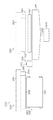
図1は本発明の第1実施形態に係る液体吐出装置の構成を示す模式図である。図1に示すように、この液体吐出装置10は、液体吐出ヘッド(以下「ヘッド」という。)と、ヘッド20のノズル面22(「液体吐出面」に相当)を払拭清掃する払拭ユニット30と、ヘッド20の側部に設けられたたるみ除去部材80とを備える。
[First Embodiment]
FIG. 1 is a schematic diagram showing the configuration of the liquid ejection apparatus according to the first embodiment of the present invention. As shown in FIG. 1, the
払拭ユニット30は、長尺状の払拭ウェブ32(「払拭部材」に相当)を供給する送出側ウェブコア34(「第1のコア」に相当)と、送出側ウェブコア34から送り出された払拭ウェブ32を巻き取る巻取側ウェブコア36(「第2のコア」に相当)と、送出側ウェブコア34から巻取側ウェブコア36に至るウェブ搬送経路の途中に配置されて払拭ウェブ32が巻き掛けられ、当該払拭ウェブ32をヘッド20のノズル面22に押圧当接させる押圧ロール40(「押圧部材」に相当)と、押圧ロール40を図1の上方向(払拭時にヘッド20のノズル面22に向かって押圧ロール40を押し付ける方向)に付勢する付勢バネ42(「弾性部材」に相当)と、払拭ウェブ32を搬送駆動するウェブ駆動ロール50と、を備える。
The wiping
また、液体吐出装置10は、ヘッド20を払拭ユニット30に対して相対移動させる相対移動機構90(「相対移動手段」に相当)を備える。ここでは、払拭ユニット30に対してヘッド20を図1の左から右に向かって矢印A方向に平行移動させる例を説明するが、相対移動の方法はこの例に限らない。
Further, the
例えば、停止したヘッド20に対して払拭ユニット30を図1の右から左の方向(矢印A方向と逆方向)に移動させる構成を採用してもよいし、ヘッド20と払拭ユニット30をそれぞれ互いに逆方向に移動させる構成であってもよい。
For example, a configuration in which the
払拭ウェブ32は、例えば、PET(Polyethylene terephthalate;ポリエチレンテレフタラート)、PEポリエチレン (Polyethylene;ポリエチレン)、NY(NYLON;ナイロン)等の極微細繊維を用いた編み又は織りからなるシートで構成され、ヘッド20のノズル面22の幅に対応した幅を有する帯状に形成される。この払拭ウェブ32は、送出側ウェブコア34にロール状に巻かれ、先端が巻取側ウェブコア36に固定された状態で提供される。
The wiping
送出側ウェブコア34は、一端が固定されて水平に支持された送出軸(不図示)に嵌められて装着されている。この送出軸は二重管構造とされ、内筒の周りを外筒が回転可能に支持される。内筒と外筒との間には、逆回転防止機構及びフリクション機構が配置され、外筒は一定の抵抗をもって一方向(払拭ウェブ32の送出方向)にのみ回転するように構成される。
The delivery-
巻取側ウェブコア36は、回転自在に水平に支持された巻取軸(不図示)に嵌めて装着されている。巻取軸はウェブ駆動ロール50の回転駆動と連動して一方向(払拭ウェブ32の巻取方向、図1において反時計回り方向)に回転する。なお、巻取軸に連結される巻取モータは、ウェブ駆動ロール50を回転駆動する図示せぬモータ(以下「ウェブ搬送モータ」という。)と兼用することができる。巻取側ウェブコア36の巻取軸は二重構造とされ、内筒の周りを外筒が回転可能に支持される。内筒と外筒との間には、トルクリミッタが配置され、一定以上の負荷(トルク)が掛かると、内筒に対して外筒が滑るように構成される。これにより、払拭ウェブ32に過剰な張力がかかるのを防止できる。
The winding-
押圧ロール40は、その軸部の一端が回転自在に支持されて水平に設置される。押圧ロール40には、ゴムロールなど弾性変形可能な弾性体ロールが用いられる。押圧ロール40は払拭ウェブ32の幅に対応したロール幅を有しており、この押圧ロール40は付勢バネ42によって図1の上方向に付勢されている。すなわち、払拭ウェブ32は押圧ロール40を介して付勢バネ42の力で図1の上方向に付勢されている。付勢バネ42が圧縮され、その弾性変形による力と、押圧ロール40の弾性変形による復元力とによって払拭ウェブ32をヘッド20のノズル面22に所定の圧力で当接させる。
The
払拭ウェブ32を搬送駆動するためのウェブ駆動ロール50(「払拭部材搬送手段」に相当)は、払拭ウェブ32を挟んで対向配置されるロール対で構成される。ウェブ駆動ロール50にはウェブ搬送モータ(図1中不図示、図4の符号116参照)が連結されており、該モータを駆動することでロール対に挟まれた払拭ウェブ32が搬送される。ウェブ駆動ロール50は巻取側ウェブコア36の近くに配置され、ウェブ駆動ロール50の回転に連動して巻取側ウェブコア36の巻取軸が回転駆動される。
The
また、この払拭ユニット30は、押圧ロール40の手前に洗浄液付与部60が設けられており、払拭ウェブ32の搬送経路には送出側ウェブコア34から送り出された払拭ウェブ32を洗浄液付与部60へガイドする第1ガイドロール72と、洗浄液付与部60による洗浄液付与後の払拭ウェブ32を押圧ロール40へと導く第2ガイドロール76とを備える。
Further, the wiping
洗浄液付与部60には、洗浄液付与ロール(転写ロール)62が配置される。図示は省略するが、洗浄液付与部60には、洗浄液を貯留する洗浄液トレイ(容器)と、洗浄液トレイの洗浄液に一部が浸漬されるアニロクスロールと、アニロクスロールに当接してアニロクスロールの表面の余剰液を除去するドクターブレードと、アニロクスロールに当接して回転する中間ロールなどが設けられ、この中間ロールの表面に保持された洗浄液が洗浄液付与ロール(転写ロール)62の表面に転写される。なお、アニロクスロールは、表面に洗浄液を保持するための多数のセルが形成された計量ロールであり、払拭ウェブ32の幅に対応した幅を有している。中間ロールと洗浄液付与ロール62も払拭ウェブ32の幅に対応した幅を有しており、アニロクスロール、中間ロールを介して洗浄液付与ロール62の表面に洗浄液が供給される。この洗浄液付与ロール62は、払拭ウェブ32に当接して払拭ウェブ32の搬送方向と同方向に回転しており、洗浄液付与ロール(転写ロール)の表面に保持された洗浄液が払拭ウェブ32に供給される。これにより、払拭ウェブ32に洗浄液が吸収される。
A cleaning liquid application roll (transfer roll) 62 is disposed in the cleaning liquid application unit 60. Although not shown, the cleaning liquid application unit 60 includes a cleaning liquid tray (container) for storing the cleaning liquid, an anilox roll partially immersed in the cleaning liquid in the cleaning liquid tray, and an anilox roll in contact with the anilox roll. A doctor blade that removes excess liquid on the surface of the roller and an intermediate roll that rotates in contact with the anilox roll are provided. The cleaning liquid held on the surface of the intermediate roll is applied to the surface of the cleaning liquid application roll (transfer roll) 62. Transcribed. The anilox roll is a measuring roll having a number of cells for holding the cleaning liquid on the surface, and has a width corresponding to the width of the wiping
本例では払拭ウェブ32に対する洗浄液の供給手段として塗布ローラ方式を採用しているが、これに代えて、液体噴射ノズルから洗浄液を噴射することによって払拭ウェブ32に洗浄液を付与する構成を採用することもできる。
In this example, the application roller system is adopted as a means for supplying the cleaning liquid to the wiping
なお、既述のとおり、払拭ウェブ32は、送出側ウェブコア34にロール状に巻かれた状態で提供されるため、払拭ユニット30への装着(交換)もこの状態で行われる。具体的には、送出側ウェブコア34を送出軸に嵌めて装着したのち、第1ガイドロール72、第2ガイドロール76、押圧ロール40に順に巻き掛け、巻取側ウェブコア36を巻取軸に嵌めて、装着を完了する。
In addition, since the wiping
ウェブ駆動ロール50を回転駆動することにより、送出側ウェブコア34から払拭前の払拭ウェブ32が送り出される。送り出された払拭ウェブ32は、第1ガイドロール72、第2ガイドロール76、押圧ロール40を順次経由して搬送され、巻取側ウェブコア36に巻き取られて回収される。
By rotating and driving the
また、図1には示されていないが、液体吐出装置10は、払拭ユニット30を図1の上下方向(z軸の方向)に昇降移動させることができる昇降機構を備えている。この昇降機構で払拭ユニット30のz方向位置を変更することができ、押圧ロール40に巻き掛けられた払拭ウェブ32の最上部の高さ位置(符号38)を可変調整することができる。
Although not shown in FIG. 1, the
たるみ除去部材80は、払拭ウェブ32の当接時に発生するたるみを除去する手段として設けられた部材である。たるみ除去部材80は、払拭動作時に相対移動機構90によってヘッド20を移動させる方向(図1の矢印Aで示す進行方向)の前側のヘッド側部に配置されている。また、たるみ除去部材80は、ヘッド20のノズル面22と同一の平面に配置される平面部82を有している。ここでいう「同一の平面」とは、厳密に一致する平面である場合に限らず、機械的な取り付け精度の誤差の範囲で若干の差を有する面など、実質的に同一の平面と見なすことができる略同一の平面も含むものとする。
The sagging removing
たるみ除去部材80の平面部82とヘッド20のノズル面22とは、実質的に単一の平面とみなせる程度に連続的に(大きな段差がなく)繋がっており、払拭ウェブ32の当接対象がたるみ除去部材80からヘッド20のノズル面22へと切り替わる際にも押圧ロール40の上下動は殆どなく、滑らかな摺動が可能である。
The
たるみ除去部材80は、ヘッド20の構成部品とは別の部品(別部材)としてヘッド20に取り付けられる構成であってもよいし、ヘッド20の構成部品の一部としてヘッド20に取り付けられる構成であってもよい。例えば、ヘッド20のノズル面22を構成するノズルプレートにたるみ除去部材80の平面部82として機能するたるみ除去領域を一体的に形成するなど、たるみ除去部材80をヘッド20と一体に構成することも可能である。
The sagging removing
払拭ウェブ32がたるみ除去部材80に接触する前の状態では、押圧ロール40に巻かれた払拭ウェブ32の最上部の位置38がたるみ除去部材80の平面部82の位置(すなわち、ノズル面22の位置)よりも僅かに高くなるように(例えば、約1.5mm高く)払拭ユニット30が配置される。
In a state before the wiping
本実施形態によれば、相対移動機構90によるヘッド20の移動に伴い、払拭ウェブ32がヘッド20のノズル面22(ノズルが形成されているノズル形成領域)に接触する前に、払拭ウェブ32がたるみ除去部材80に接触する。そして、払拭ウェブ32がたるみ除去部材80に接触している間に払拭ウェブ32のたるみが除去され、たるみ除去後の払拭ウェブ32がノズル面22に接触してノズル面22を払拭する。
According to the present embodiment, the wiping
<液体吐出装置10の動作説明>
次に、図1のように構成された液体吐出装置10におけるヘッド20の払拭清掃時の動作を説明する。ヘッド20のノズル面22を払拭清掃する際には、ヘッド20と払拭ユニット30の相対移動が行われる。払拭動作時に、ヘッド20を図1矢印A方向に移動させると、この相対移動に伴い、先ず、たるみ除去部材80が払拭ウェブ32に接触し、たるみ除去部材80が払拭ウェブ32の真上を通過してから、その後、ヘッド20のノズル面22(ノズルが形成されているノズル形成領域)が払拭ウェブ32に接触する。
<Description of Operation of
Next, the operation | movement at the time of the wiping cleaning of the
図2は、払拭ウェブ32をヘッド20のたるみ除去部材80に当接させた様子を示す模式図である。図1で説明したとおり、払拭ウェブ32がたるみ除去部材80に接触する前の状態において、払拭ウェブ32の最上部の位置38はたるみ除去部材80の平面部82よりも高い位置にあるため、ヘッド20を矢印A方向に移動させて図2のように押圧ロール40の真上にたるみ除去部材80を移動させると、その高低差(ヘッドとラップする量)に応じて押圧ロール40が押し下げられ、付勢バネ42が縮み、払拭ウェブ32がたるみ除去部材80に当接する。
FIG. 2 is a schematic view showing a state in which the wiping
このように付勢バネ42の収縮を伴って払拭ウェブ32をたるみ除去部材80の平面部82に当接させたとき、図2に示すように、押圧ロール40の両側(前後)にウェブのたるみ102が発生する。しかし、ウェブ駆動ロール50の駆動によるウェブ搬送により、このたるみ102は次第に吸収される。ヘッド20と払拭ウェブ32の相対移動によってたるみ除去部材80の平面部82が押圧ロール40の上を通過し終えるまでの間(払拭ウェブ32がたるみ除去部材80に当接している期間内)にたるみ102は解消される。
When the wiping
このため、図3に示すように、払拭ウェブ32がヘッド20のノズル面22と接触する時には、たるみ102は無くなっており(或いは、実質的に問題の無いたるみ量に低減されている状態も含む)、たるみ102の無い状態でノズル面22を払拭することができる。
For this reason, as shown in FIG. 3, when the wiping
払拭ウェブ32がヘッド20のノズル面22の払拭を開始する時点でたるみ102が除去されている状態が得られるように、たるみ除去部材80の平面部82の大きさ(相対移動方向の長さL)は、当接時に発生する払拭ウェブ32のたるみ102の量(たるみ量)と、ヘッド移動速度(相対移動速度)、ウェブ駆動ロール50によるウェブ搬送速度を考慮して設計される。ヘッド移動速度やウェブ搬送速度は、払拭ウェブ32の物性、洗浄液の特性、相対移動機構90の制御性、生産性、ウェブ使用量などを総合的に考慮して決定されるが、一般的には、ウェブ搬送速度はヘッド移動速度(相対移動の速度)に比べて十分に小さい速度に設定される。例えば、ウェブ搬送速度は、ヘッド移動速度の1/10以下の速さに設定される。好ましくはウェブ搬送速度がヘッド移動速度の1/20以下の速さに設定される。
The size (the length L in the relative movement direction) of the
一例として、ヘッド移動速度80mm/sec、ウェブ搬送速度3.2mm/secにて、L=100mmのたるみ除去部材80を取り付けて、払拭ウェブ32のたるみ(たるみ量約3mm)を除去することができた。
As an example, a
ウェブ駆動ロール50の駆動によるウェブ搬送速度が速いほど、たるみ102の除去に要する時間を短縮することができる。ただし、ウェブ搬送速度を高速にするとその分、ウェブの使用量が増加することになる。したがって、ウェブ使用量をできるだけ抑制する観点から、ウェブ駆動ロール50の駆動速度を適切に制御することが好ましい。
The faster the web transport speed by driving the
例えば、払拭ウェブ32がたるみ除去部材80に接触している限られた時間内のみウェブ駆動ロール50を高速駆動し、たるみ除去後に通常の駆動(低速駆動)に戻すという制御を採用することができる。或いはまた、たるみを検知するセンサを併用し、たるみの有無を検知して高速駆動と通常駆動の切り替えを行うことも好ましい。
For example, it is possible to employ a control in which the
たるみが除去された払拭ウェブ32を搬送走行させながら、その走行方向(ウェブ搬送方向)と逆方向にヘッド20と払拭ユニット30を相対移動させ、払拭ウェブ32をヘッド20のノズル面22に摺動させつつノズル面22を払拭清掃する。払拭ユニット30に対してヘッド20が相対的に移動することで払拭ウェブ32の払拭位置(当接位置)が順次変更され、ノズル面22の全域が払拭ウェブ32によって順次拭き取られていく。この相対移動中、払拭ウェブ32自体もウェブ駆動ロール50によって搬送され、払拭ウェブ32のノズル面22に当接する当接領域(拭き取り面)が順次更新される。このため、拭き取り部には常に新しい払拭ウェブ32の拭き取り面が供給される。
The
本実施形態によれば、汚れた面でヘッド20を生成することがなく、ヘッドの清掃性の向上を図ることができる。その結果、ヘッド20からの吐出安定性を向上させることができる。
According to the present embodiment, the
図1に示した第1実施形態において、払拭ユニット30、たるみ除去部材80、相対移動機構90の組み合わせが「液体吐出ヘッドの清掃装置」に相当する。
In the first embodiment shown in FIG. 1, the combination of the wiping
〔第2実施形態〕
図4は第2実施形態に係る液体吐出装置110の構成を示す模式図である。図4中、図1乃至図3で説明した第1実施形態と同一又は類似の要素には同一の符号を付し、その説明は省略する。
[Second Embodiment]
FIG. 4 is a schematic diagram illustrating a configuration of the
図4に示す第2実施形態の液体吐出装置110は、払拭ウェブ32のたるみ102を検知するたるみセンサ114(「検知手段」に相当)と、たるみセンサ114からの検知信号に基づいてウェブ搬送モータ116の駆動を制御する制御回路120(「制御手段」に相当)と、を備える。
The
払拭ウェブ32のたるみ102を検知する手段としては、例えば、レーザやLED(発光ダイオード)などの発光素子から払拭ウェブ32に向けて光を照射し、その反射光を受光素子(光電変換素子)で受光する反射型の光センサを用いることができる。たるみ102が発生していないときには払拭ウェブ32からの反射光が無く、たるみ102が発生するとそのたるみ102部分の払拭ウェブ32から反射光が受光素子で受光され、受光量に応じた電気信号が得られる。このような構成により、払拭ウェブ32からの反射光の有無によって、たるみを検知することができる。たるみセンサ114からの検知信号は制御回路120に送られる。
As means for detecting the
制御回路120は、中央演算処理装置(CPU)及びその周辺回路で構成することができる。制御回路120は、相対移動機構90の駆動源となるモータ(相対移動モータ)92を制御するとともに、ウェブ駆動ロール50の駆動源となるウェブ搬送モータ116を制御する。
The
図5は、第2実施形態の液体吐出装置110の制御例を示すフローチャートである。このフローチャートに沿って液体吐出装置110の動作を説明する。
FIG. 5 is a flowchart illustrating a control example of the
払拭清掃を実行する払拭指示が与えられ、図5のフローチャートの処理が開始されると、まず、相対移動モータ92を駆動して、ヘッド20を払拭ユニット30に向けて図4の矢印A方向に移動させる(ステップS11)。この移動開始と同時に、または、移動開始後の適宜のタイミングでウェブ搬送モータ116の駆動を開始する(ステップS12)。この時の駆動速度は、ノズル面22を拭き取る時の払拭ウェブ32の搬送速度(第1の搬送速度)を実現する通常回転の速度とする。制御回路120はたるみセンサ114からの検知信号を監視し、払拭ウェブ32のたるみか検知されたか否かの判断を行う(ステップS13)。
When a wiping instruction for performing wiping and cleaning is given and the processing of the flowchart of FIG. 5 is started, first, the
たるみ除去部材80に払拭ウェブ32が当接し、この当接によって発生したたるみ102をたるみセンサ114で検知すると(図6参照)、ウェブ搬送モータ116を高速駆動する(図5のステップS14)。通常回転よりも高速に駆動することにより、比較的短時間で払拭ウェブ32のたるみ102が除去される。制御回路120はたるみセンサ114からの検知信号の監視を継続しており、払拭ウェブ32のたるみが解消されたか否かの判断を行う(ステップS15)。たるみ102が解消され、たるみセンサ114がたるみ102を検知しなくなると、ウェブ搬送モータ116を通常回転に戻す制御が行われる(ステップS16)。なお、通常回転の駆動速度が「第1の駆動速度」に相当し、高速駆動時の駆動速度が「第2の駆動速度」に相当する。
When the wiping
これにより、払拭ウェブ32がヘッド20のノズル面22と接触する時には、たるみ102は無くなっており(図7参照)、たるみ102の無い状態でノズル面22の払拭を開始することができる。その後、この通常回転で払拭ウェブ32を走行させながら、ヘッド20と払拭ユニット30を相対移動させ、ヘッド20のノズル面22を払拭清掃する。
Thereby, when the wiping
ノズル面22の全域の払拭清掃が終了したか否かの判定がなされ(図5のステップS17)、未終了であれば清掃を継続する。例えば、相対移動機構90の移動量を検知するエンコーダ等の信号に基づいて払拭清掃が終了したか否かを判断することができる。
It is determined whether or not the wiping and cleaning of the entire area of the
払拭清掃が完了したら、相対移動モータ92を停止させ(ステップS18)、ウェブ搬送モータ116も停止させる(ステップS19)。こうして、払拭清掃の処理が終了する。
When the wiping cleaning is completed, the
なお、その後、ヘッド20を元の位置(描画位置)に戻す際には、払拭ウェブ32がヘッド20に接触しない高さとなる所定の退避位置まで払拭ユニット30を下降させてから、ヘッド20を矢印A方向と逆方向に移動させる。
After that, when the
この第2実施形態によれば、第1実施形態で得られる作用効果に加えて、払拭ウェブ32の使用量を抑えることができるとともに、たるみ除去に要する時間を短縮することができる。また、たるみ除去に要する時間が短くなる分、たるみ除去部材80を小さくする(相対移動方向の長さLを短くする)ことができる。
According to this 2nd Embodiment, in addition to the effect obtained by 1st Embodiment, while being able to suppress the usage-amount of the wiping
なお、第2実施形態において、相対移動機構90と相対移動モータ92の組み合わせが「相対移動手段」に相当すし、ウェブ駆動ロール50とウェブ搬送モータ116の組み合わせが「払拭部材搬送手段」に相当する。
In the second embodiment, the combination of the
<変形例1>
第2実施形態とは別の方法として、たるみセンサ114を省略して、払拭ウェブ32がたるみ除去部材80に接触するタイミングでウェブ搬送モータ116を高速駆動する方法がある。例えば、払拭ウェブ32をたるみ除去部材80に接触させた時点からウェブ搬送モータ116を高速駆動し、たるみ除去に要する時間として予め設定された所定時間経過後に、通常回転(低速駆動)に戻すという制御を行うことが可能である。この場合、高速駆動を継続する所定時間の設定に際しては、ウェブ搬送速度、ヘッド相対速度、発生するたるみ量など、様々な条件に応じて実験的に所要時間を調べておき、適度なマージンを付加したものを用いることができる。
<Modification 1>
As a method different from the second embodiment, there is a method in which the
かかる態様によれば、第2実施形態と同様に、短時間でたるみを除去することが可能である。ただし、たるみセンサを使用した場合と比較して、高速駆動時間が長くなる分、払拭ウェブ32の使用量が若干増加する。
According to this aspect, as in the second embodiment, it is possible to remove the sag in a short time. However, the amount of use of the wiping
<変形例2>
第1実施形態及び第2実施形態では、ヘッド20と払拭ユニット30の高さ方向(z方向)の相対位置については、払拭ユニット30を上下方向に昇降移動させるものとして説明したが、これに代えて、又はこれと組み合わせて、ヘッド20を上下方向に昇降移動させる機構を採用することができる。
<
In the first embodiment and the second embodiment, the relative position in the height direction (z direction) of the
<インクジェット記録装置への適用例>
次に、上述した液体吐出装置10又は110をインクジェット記録装置に適用した例を説明する。
<Application example to inkjet recording apparatus>
Next, an example in which the
図8は、インクジェット記録装置210の要部の構成を示す正面図、図9は平面図、図10は側面図である。これらの図面に示したように、このインクジェット記録装置210は、シングルパス方式のラインプリンタであり、記録媒体である用紙(枚葉紙)Pを搬送する用紙搬送機構220(「媒体搬送手段」に相当)と、用紙搬送機構220によって搬送される用紙Pに向けてシアン(C)、マゼンタ(M)、イエロー(Y)、黒(K)の各色インク滴を吐出するヘッドユニット230と、ヘッドユニット230に搭載された各色のヘッド232(「液体吐出ヘッド」に相当)のメンテナンスを行うメンテナンスユニット240と、ヘッドユニット230に装着された各ヘッド232のノズル面を清掃するノズル面清掃装置250とで構成される。図8のヘッド232が図1及び図4のヘッド20に相当し、図8のノズル面清掃装置250が図1及び図4の払拭ユニット30に対応する。
8 is a front view showing a configuration of a main part of the ink
図8に示した用紙搬送機構220は、ベルト搬送機構で構成され、走行するベルト222に用紙Pを吸着させて用紙Pを搬送する。
The
図9に示すように、ヘッドユニット230は、シアン(C)のインク滴を吐出するヘッド232Cと、マゼンタ(M)のインク滴を吐出するヘッド232Mと、イエロー(Y)のインク滴を吐出するヘッド232Yと、黒(K)のインク滴を吐出するヘッド232Kと、を備える。各ヘッド232C、232M、232Y、232Kは、印刷対象とする用紙Pの最大用紙幅に対応したラインヘッドで構成される。
As shown in FIG. 9, the
また、各ヘッド232C、232M、232Y、232Kの側部には、たるみ除去部材280C、280M、280Y、280Kが設けられている。なお、たるみ除去部材280C、280M、280Y、280Kを備えた各ヘッド232C、232M、232Y、232Kの構成は共通するため、以下の説明おいては、特にインク色を区別する場合を除いて、たるみ除去部材280、ヘッド232と記載する。
Further, slack removing
たるみ除去部材280は、図1で説明したたるみ除去部材80に相当する部材である。たるみ除去部材280は、ヘッド232のノズル面233と同一の平面に配置された平面部282を有している。
The sagging removing
ヘッドユニット230は、各ヘッド232が取り付けられるヘッド支持フレーム234と、ヘッド支持フレーム234を移動させるヘッド支持フレーム移動機構(不図示)とを備える。
The
ヘッド支持フレーム234は、各ヘッド232を取り付けるためのヘッド取付部(不図示)を備えている。各ヘッド232は、このヘッド取付部に着脱自在に取り付けられる。ヘッド取付部は、ヘッド支持フレーム234に昇降自在に設けられており、図示しない昇降機構によって昇降する。ヘッド取付部に取り付けられた各ヘッド232は、この昇降機構によって、用紙Pの搬送面に対して垂直に昇降する。
The
ヘッド支持フレーム234に取り付けられた各ヘッド232は、用紙Pの搬送方向に対して直交して配置される。また、各ヘッド232は用紙Pの搬送方向に沿って所定の順で一定の間隔をもって配置される。なお、本例では、CMYKの標準色(4色)の構成を例示したが、インク色や色数の組み合わせについては本実施形態に限定されず、必要に応じて淡インク、濃インク、特別色インクを追加してもよい。例えば、ライトシアン、ライトマゼンタなどのライト系インクを吐出するインクジェットヘッドを追加する構成も可能であり、各色ヘッドの配置順序も特に限定はない。
Each
ヘッド支持フレーム移動機構は、用紙搬送機構220の上方位置でヘッド支持フレーム234を用紙Pの搬送方向に対して直交する方向に水平にスライド移動させる。この「ヘッド支持フレーム移動機構」が図1の「相対移動機構90」に相当する。
The head support frame moving mechanism slides the
ヘッド支持フレーム移動機構は、例えば、用紙搬送機構220を跨いで水平に設置される天井フレームと、その天井フレームに敷設されるガイドレールと、ガイドレール上をスライド移動する走行体と、その走行体をガイドレールに沿って移動させる駆動手段(例えば、送りねじ機構など)で構成される。ヘッド支持フレーム234は、走行体に取り付けられて、水平にスライド移動する。
The head support frame moving mechanism includes, for example, a ceiling frame installed horizontally across the
ヘッド支持フレーム234は、ヘッド支持フレーム移動機構に駆動されて、所定の「画像記録位置(描画位置)」と「メンテナンス位置」との間を移動可能に設けられる。ヘッド支持フレーム234は、画像記録位置に位置すると、用紙搬送機構220の上方に配置される。これにより、用紙搬送機構220によって搬送される用紙Pに対して印刷可能になる。
The
一方、メンテナンス位置に位置すると、メンテナンスユニット240の設置位置に配置される。
On the other hand, when it is located at the maintenance position, it is arranged at the installation position of the
メンテナンスユニット240には、各ヘッド232のノズル面233を覆うキャップ242(242C、242M、242Y、242K)が備えられる。装置を長時間停止する場合などは、このメンテナンスユニット240の設置位置(メンテナンス位置)にヘッド232を移動させ、ノズル面233をキャップ242で覆う。これにより、乾燥による不吐出が防止される。
The
このキャップ242には、ノズル内を加圧・吸引するための加圧・吸引機構(不図示)、及び、キャップ242内に洗浄液を供給するための洗浄液供給機構(不図示)が備えられる。また、キャップ242の下方位置には廃液トレイ244が配置される(図8参照)。キャップ242に供給された洗浄液は、この廃液トレイ244に廃棄され、廃液トレイ244から廃液回収配管246を介して廃液タンク248に回収される。
The
ノズル面清掃装置250は、用紙搬送機構220とメンテナンスユニット240との間に配置される。ノズル面清掃装置250は、ヘッド支持フレーム234が、画像記録位置からメンテナンス位置に移動する際に、払拭ウェブ312でヘッド232のノズル面233を払拭することで、ノズル面233を清掃する。この払拭ウェブ312が図1で説明した払拭ウェブ32に相当する。
The nozzle
ノズル面清掃装置250は、払拭装置本体フレーム252に取り付けられる払拭ユニット300C、300M、300Y、300Kと、払拭装置本体フレーム252を昇降させる払拭装置本体昇降機構(不図示)とから構成される。
The nozzle
払拭ユニット300C、300M、300Y、300Kは、帯状に形成された払拭ウェブ312を走行させながらヘッド232のノズル面233に当接させて、ノズル面233を払拭する。払拭ユニット300C、300M、300Y、300Kは、ヘッドごとに設けられ、ヘッド232の設置間隔に合わせて、払拭装置本体フレーム252に設置される。なお、各払拭ユニット300C、300M、300Y、300Kの構成は同じなので、ここでは払拭ユニット300として説明する。払拭ユニット300の構成は、図1及び図4で説明した払拭ユニット30の構成と同様である。
The wiping units 300 </ b> C, 300 </ b> M, 300 </ b> Y, and 300 </ b> K wipe the
<ヘッドの構成例>
図11は、ヘッド232の平面透視図である。ヘッド232のノズル面233には、インク滴を吐出する複数のノズル235が形成されている。本実施形態のヘッド232は、いわゆるマトリックスヘッドで構成され、複数のノズル235は二次元マトリクス状に配置される。ノズル面233に多数のノズルを二次元的に配列させる構成によって、ヘッド232の長手方向(用紙搬送方向と直交する用紙幅方向)に沿って実質的に並ぶノズルのノズル間隔を狭めることができ、高記録解像度を実現できる。
<Example of head configuration>
FIG. 11 is a plan perspective view of the
二次元ノズル配列を有するインクジェットヘッド(マトリクスヘッド)の場合、当該二次元ノズル配列における各ノズルを媒体搬送方向(「副走査方向」に相当)と直交する方向(「主走査方向」に相当)に沿って並ぶように投影(正射影)した投影ノズル列は、主走査方向(媒体幅方向)について、記録解像度を達成するノズル密度でノズルが概ね等間隔で並ぶ一列のノズル列と等価なものと考えることができる。「概ね等間隔」とは、インクジェット印刷システムで記録可能な打滴点として実質的に等間隔であることを意味している。例えば、製造上の誤差や着弾干渉による媒体上での液滴の移動を考慮して僅かに間隔を異ならせたものなどが含まれている場合も「等間隔」の概念に含まれる。投影ノズル列(「実質的なノズル列」ともいう。)を考慮すると、主走査方向に沿って並ぶ投影ノズルの並び順に、ノズル位置(ノズル番号)を対応付けることができる。以下の説明で「ノズル位置」という場合、この実質的なノズル列におけるノズルの位置を指す。 In the case of an inkjet head (matrix head) having a two-dimensional nozzle array, each nozzle in the two-dimensional nozzle array is in a direction (corresponding to “main scanning direction”) orthogonal to the medium transport direction (corresponding to “sub-scanning direction”). The projection nozzle row projected so as to line up (orthogonal projection) is equivalent to a nozzle row in which the nozzles are arranged at substantially equal intervals at a nozzle density that achieves the recording resolution in the main scanning direction (medium width direction). Can think. The “substantially equidistant” means that the droplet ejection points that can be recorded by the ink jet printing system are substantially equidistant. For example, the concept of “equally spaced” also includes cases where the intervals are slightly different in consideration of manufacturing errors and movement of droplets on the medium due to landing interference. Considering projection nozzle rows (also referred to as “substantial nozzle rows”), nozzle positions (nozzle numbers) can be associated with the order of projection nozzles arranged along the main scanning direction. In the following description, “nozzle position” refers to the position of the nozzle in this substantial nozzle row.
また、本発明の実施に際してヘッド232におけるノズル235の配列形態は図示の例に限定されず、様々なノズル配置構造を適用できる。例えば、図11で説明したマトリクス配列に代えて、一列の直線配列、V字状のノズル配列、V字状配列を繰り返し単位とするジグザク状(W字状など)のような折れ線状のノズル配列なども可能である。
In the implementation of the present invention, the arrangement form of the
このようなノズル列を備えるヘッド232に対して用紙P(記録媒体)を相対的に移動させる動作を1回行うだけで(1回の副走査で)、用紙Pの画像形成領域に所定記録解像度(例えば、1200dpi)の画像を記録することができる。
The operation of moving the paper P (recording medium) relative to the
<吐出方式について>
本実施形態のヘッド232は、いわゆるピエゾ方式によってノズル235からインクの液滴を吐出させるものである。各ノズル235は、それぞれ圧力室236に連通されており、この圧力室236の壁面(例えば、ノズル235からの液滴の吐出方向を下方としたときの圧力室236の上面)を図示せぬ圧電素子で振動させることにより、ノズル235から液滴が吐出される。なお、インクジェットヘッドにおける各ノズルから液滴を吐出させるための吐出用の圧力(吐出エネルギー)を発生させる手段は、ピエゾアクチュエータ(圧電素子)に限らない。圧電素子の他、静電アクチュエータ、サーマル方式(ヒータの加熱による膜沸騰の圧力を利用してインクを吐出させる方式)におけるヒータ(加熱素子)や他の方式による各種アクチュエータなど様々な圧力発生素子(吐出エネルギー発生素子)を適用し得る。ヘッドの吐出方式に応じて、相応のエネルギー発生素子が流路構造体に設けられる。
<Discharge method>
The
<たるみ除去部材について>
たるみ除去部材280は、ヘッド232のノズル面233の外側(払拭時のヘッド進行方向の前側)に配置されており、ノズル面清掃装置250(図8,図9参照)の払拭ウェブ312がヘッド232のノズル形成領域に接触する前に(ノズル面233の払拭を開始する前に)、払拭ウェブ312がたるみ除去部材280に当接する。これにより、当接時に発生する払拭ウェブ312のたるみをたるみ除去部材280で除去することができる。
<About slack removing member>
The
<ノズル面の清掃動作について>
ノズル面清掃装置250は、ヘッド232が画像記録位置からメンテナンス位置へ移動する過程において、払拭ウェブ312を走行させながらヘッド232のノズル面233に摺動させてノズル面233を払拭する。
<About the cleaning operation of the nozzle surface>
Nozzle
ノズル面清掃装置250は、清掃時以外においては所定の待機位置に位置しており、清掃時には待機位置から所定量上昇した位置である所定の作動位置に位置する。ノズル面清掃装置250が所定の作動位置に位置した状態では、払拭ユニット300によって、ノズル面233を払拭することが可能となる。すなわち、各ヘッド232が、各払拭ユニット300の上を通過する際、そのノズル面233に払拭ウェブ312を押圧当接することが可能になる。
The nozzle
ノズル面の清掃指示が与えられ、ノズル面洗浄モードに入ると、ヘッド232を画像記録位置からメンテナンス位置に移動する。ヘッド232が所定の位置に到達すると、払拭ウェブ312はヘッド232の進行方向と逆向きに搬送される。払拭ウェブ312がたるみ除去部材280に当接した際に発生するたるみは、払拭ウェブ312がたるみ除去部材280に接触している間に解消され、たるみが除去された状態で払拭ウェブ312がノズル面233に接触する。払拭ウェブ312がノズル面233の移動方向と逆方向に走行してノズル面233を払拭することにより、効率よくノズル面233を払拭することができる。また、常に払拭ウェブ312の新しい面(未使用領域)を使ってノズル面233を払拭することができる。
When a nozzle surface cleaning instruction is given and the nozzle surface cleaning mode is entered, the
<他の変形例>
また、上記実施形態では、記録媒体の全幅に対応する長さのノズル列を有するページワイドのフルライン型ヘッドを用いたインクジェット記録装置(1回の副走査によって画像を完成させるシングルパス方式の画像形成装置)を説明したが、本発明の適用範囲はこれに限定されず、シリアル型(シャトルスキャン型)ヘッドなど、短尺の記録ヘッドを移動させながら、複数回のヘッド走査により画像記録を行うインクジェット記録装置についても本発明を適用できる。
<Other variations>
Further, in the above embodiment, an inkjet recording apparatus using a page-wide full-line head having a nozzle row having a length corresponding to the entire width of the recording medium (single-pass image for completing an image by one sub-scanning). However, the scope of application of the present invention is not limited to this, and an inkjet that performs image recording by scanning a plurality of heads while moving a short recording head such as a serial (shuttle scan) head. The present invention can also be applied to a recording apparatus.
<払拭清掃時のヘッド移動方向について>
上記実施形態ではヘッドを画像記録位置からメンテナンス位置に移動させる過程でノズル面を払拭清掃したが、これに代えて、又はこれと組み合わせて、ヘッドをメンテナンス位置から画像記録位置へ移動させる過程においてノズル面を払拭清掃してもよい。
<About the direction of head movement during wiping and cleaning>
In the above embodiment, the nozzle surface is wiped and cleaned in the process of moving the head from the image recording position to the maintenance position, but instead of or in combination with this, the nozzle is moved in the process of moving the head from the maintenance position to the image recording position. The surface may be wiped clean.
さらに、上記実施形態では払拭部材はヘッドのノズル面の短手方向の幅に対応した幅を有し、ノズル面を長手方向に払拭したが、払拭方向はこの方向に限られない。例えば、ノズル面の長手方向の幅に対応した幅を有する払拭部材を用いて、ノズル面を短手方向に払拭してもよい。 Further, in the above embodiment, the wiping member has a width corresponding to the width in the short direction of the nozzle surface of the head, and the nozzle surface is wiped in the longitudinal direction, but the wiping direction is not limited to this direction. For example, the nozzle surface may be wiped in the short direction by using a wiping member having a width corresponding to the width in the longitudinal direction of the nozzle surface.
いずれの形態においても、払拭部材がヘッドのノズル面(ノズルの形成領域)に接触する前に、払拭部材がたるみ除去部材に接触するように、ヘッドと払拭部材との相対的な移動方向を考慮して、ノズル形成領域の外側にたるみ除去部材が設けられる。 In any form, the relative movement direction of the head and the wiping member is considered so that the wiping member contacts the slack removing member before the wiping member contacts the nozzle surface (nozzle formation region) of the head. Then, a sag removing member is provided outside the nozzle formation region.
<ヘッドと記録媒体とを相対移動させる手段について>
上述の実施形態では、停止したヘッドに対して記録媒体を搬送する構成を例示したが、本発明の実施に際しては、停止した記録媒体(被描画媒体)に対してヘッドを移動させる構成も可能であり、また、両者を移動させる構成も可能である。
<Means for relatively moving the head and the recording medium>
In the above-described embodiment, the configuration in which the recording medium is transported to the stopped head is exemplified. However, in the implementation of the present invention, a configuration in which the head is moved with respect to the stopped recording medium (the drawing medium) is also possible. In addition, a configuration in which both are moved is also possible.
なお、シングルパス方式のフルライン型の記録ヘッドは、通常、記録媒体の送り方向(搬送方向)と直交する方向に沿って配置されるが、搬送方向と直交する方向に対して、ある所定の角度を持たせた斜め方向に沿ってヘッドを配置する態様もあり得る。その場合であっても、交差する2軸(第1方向、第2方向)を定義することで、実質的なノズル列方向などを特定することが可能である。 A single-pass type full-line type recording head is usually arranged along a direction orthogonal to the feeding direction (conveying direction) of the recording medium. There may be a mode in which the head is disposed along an oblique direction with an angle. Even in such a case, it is possible to specify a substantial nozzle row direction and the like by defining two intersecting axes (first direction and second direction).
また、上述の実施形態では、媒体搬送手段として、ベルト搬送方式の用紙搬送機構220を例示したが、ベルト搬送方式に限らず、ドラムの周面に記録媒体を巻き付けて搬送するドラム搬送方式を採用することもできる。
In the above-described embodiment, the belt conveyance type
<ノズル面の向きについて>
上記実施形態ではヘッドのノズル面を水平面とし、液滴の吐出方向を鉛直下方としたが、ヘッドのノズル面を水平面に対して一定の角度傾斜させた構成とすることもできる。この場、ノズル面の傾斜に合わせて払拭ウェブの当接面も傾斜させる。また、たるみ除去部材の平面部をノズル面と同じ平面に配置する構成とする。
<Direction of nozzle surface>
In the above embodiment, the nozzle surface of the head is a horizontal plane, and the droplet discharge direction is vertically downward. However, the nozzle surface of the head may be inclined at a certain angle with respect to the horizontal plane. In this case, the contact surface of the wiping web is also inclined in accordance with the inclination of the nozzle surface. Moreover, it is set as the structure which arrange | positions the plane part of a slack removal member on the same plane as a nozzle surface.
<記録媒体について>
「記録媒体」は、液体吐出ヘッドから吐出された液滴によってドットが記録される媒体の総称であり、印字媒体、被記録媒体、被画像形成媒体、受像媒体、被吐出媒体、印刷用紙など様々な用語で呼ばれるものが含まれる。本発明の実施に際して、記録媒体の材質や形状等は、特に限定されず、連続用紙、カット紙、シール用紙、OHPシート等の樹脂シート、フィルム、布、不織布、配線パターン等が形成されるプリント基板、ゴムシート、その他材質や形状を問わず、様々な媒体に適用できる。
<About recording media>
“Recording medium” is a general term for a medium on which dots are recorded by droplets ejected from a liquid ejection head, and includes various media such as a printing medium, a recording medium, an image forming medium, an image receiving medium, an ejection medium, and a printing paper. That are called in simple terms. In the practice of the present invention, the material, shape, etc. of the recording medium are not particularly limited, and a print on which a resin sheet such as continuous paper, cut paper, seal paper, OHP sheet, film, cloth, nonwoven fabric, wiring pattern, or the like is formed. It can be applied to various media regardless of the substrate, rubber sheet, and other materials and shapes.
<装置応用例>
上記の実施形態では、グラフィック印刷用のインクジェット記録装置への適用を例に説明したが、本発明の適用範囲はこの例に限定されない。例えば、電子回路の配線パターンを描画する配線描画装置、各種デバイスの製造装置、吐出用の機能性液体として樹脂液を用いるレジスト印刷装置、カラーフィルター製造装置、マテリアルデポジション用の材料を用いて微細構造物を形成する微細構造物形成装置など、液状機能性材料を用いて様々な形状やパターンを描画するインクジェット装置に広く適用できる。
<Device application example>
In the above embodiment, application to an inkjet recording apparatus for graphic printing has been described as an example, but the scope of application of the present invention is not limited to this example. For example, a wiring drawing apparatus for drawing a wiring pattern of an electronic circuit, a manufacturing apparatus for various devices, a resist printing apparatus that uses a resin liquid as a functional liquid for ejection, a color filter manufacturing apparatus, and a material deposition material. The present invention can be widely applied to an inkjet apparatus that draws various shapes and patterns using a liquid functional material, such as a fine structure forming apparatus that forms a structure.
<開示する発明の各種態様>
上記に詳述した実施形態についての記載から把握されるとおり、本明細書及び図面は以下に示す発明を含む多様な技術思想の開示を含んでいる。
<Various aspects of the disclosed invention>
As will be understood from the description of the embodiment described in detail above, the present specification and drawings include disclosure of various technical ideas including the invention described below.
(第1態様):液滴を吐出するノズルが形成された液体吐出面を有する液体吐出ヘッドと、液体吐出ヘッドの液体吐出面に当接させて液体吐出面を払拭する長尺状の払拭部材と、払拭部材をその長手方向に沿って搬送駆動する払拭部材搬送手段と、払拭部材を前記液体吐出面に押圧当接させる押圧部材と、押圧当接時に弾性変形し押圧部材を介して払拭部材を液体吐出面に押し付ける力を付与する弾性部材と、液体吐出ヘッドに払拭部材を当接させながら払拭部材搬送手段の搬送駆動によって走行する払拭部材と液体吐出ヘッドとを相対移動させる相対移動手段と、相対移動による液体吐出ヘッドの払拭部材に対する進行方向前方の液体吐出ヘッドの側部に配置され、払拭部材を当接させたときに弾性部材の弾性変形によって発生する払拭部材のたるみを除去するたるみ除去部材と、を備えた液体吐出装置。 (First Aspect): A liquid discharge head having a liquid discharge surface on which nozzles for discharging liquid droplets are formed, and a long wiping member that contacts the liquid discharge surface of the liquid discharge head and wipes the liquid discharge surface A wiping member conveying unit that conveys and drives the wiping member along its longitudinal direction, a pressing member that presses and contacts the wiping member against the liquid ejection surface, and a wiping member that is elastically deformed when pressed and contacted via the pressing member An elastic member that applies a force to press the liquid ejection surface, and a relative movement unit that relatively moves the wiping member and the liquid ejection head that are driven by the conveyance drive of the wiping member conveyance unit while bringing the wiping member into contact with the liquid ejection head; The wiping portion that is disposed on the side of the liquid ejection head in the forward direction relative to the wiping member of the liquid ejection head by relative movement and is generated by elastic deformation of the elastic member when the wiping member is brought into contact Liquid discharge apparatus comprising: a slack removing member, the removing the slack.
この態様によれば、払拭部材は液体吐出ヘッドの液体吐出面に接触する前に、たるみ除去部材に当接する。この当接時に発生した払拭部材のたるみは、たるみ除去部材との接触中に除去され、たるみ除去後に払拭部材が液体吐出面に当接される。これにより、払拭部材を順次搬送しながら常に新しい払拭面で液体吐出面を払拭することができ、払拭性を向上させることができる。 According to this aspect, the wiping member comes into contact with the sag removing member before contacting the liquid ejection surface of the liquid ejection head. The slack of the wiping member generated at the time of contact is removed during the contact with the slack removing member, and after the slack is removed, the wiping member is brought into contact with the liquid ejection surface. Thereby, it is possible to always wipe the liquid discharge surface with a new wiping surface while sequentially transporting the wiping member, and it is possible to improve the wiping property.
(第2態様):第1態様に記載の液体吐出装置において、たるみ除去部材は、液体吐出ヘッドの液体吐出面と同一の面に配置された平面部を有する構成とすることが好ましい。 (Second Aspect): In the liquid ejection device according to the first aspect, it is preferable that the sag removing member has a flat portion disposed on the same surface as the liquid ejection surface of the liquid ejection head.
かかる態様によれば、たるみ除去部材の平面部に払拭部材を当接させることで発生するたるみを除去し、たるみを除去した状態の払拭部材で液体吐出面の払拭を開始することができる。 According to this aspect, it is possible to remove the sag generated by bringing the wiping member into contact with the flat surface portion of the sag removing member, and to start wiping the liquid discharge surface with the wiping member in a state where the sag is removed.
(第3態様):第1態様又は第2態様に記載の液体吐出装置において、払拭部材がたるみ除去部材に接触しているときに払拭部材を払拭部材搬送手段で搬送駆動することによりたるみが解消される構成とすることができる。 (Third Aspect): In the liquid ejection device according to the first aspect or the second aspect, the sag is eliminated by driving the wiping member with the wiping member conveying means when the wiping member is in contact with the sag removing member. Can be configured.
かかる態様によれば、払拭部材をたるみ除去部材に当接させたときに発生した払拭部材のたるみは、たるみ除去部材との接触期間中における払拭部材の搬送駆動によって吸収される。 According to this aspect, the sag of the wiping member generated when the wiping member is brought into contact with the sag removing member is absorbed by the conveyance driving of the wiping member during the contact period with the sag removing member.
(第4態様):第3態様に記載の液体吐出装置において、払拭部材搬送手段の駆動速度を制御する制御手段を備え、制御手段は、払拭部材を液体吐出ヘッドの液体吐出面に当接させて相対移動によって液体吐出面を払拭する際に払拭部材搬送手段を第1の駆動速度で駆動させ、払拭部材が前記たるみ除去部材に接触しているときに第1の駆動速度よりも高速の第2の駆動速度で払拭部材搬送手段を駆動させる構成とすることができる。 (Fourth aspect): In the liquid ejection apparatus according to the third aspect, the liquid ejection apparatus includes a control unit that controls a driving speed of the wiping member conveying unit, and the control unit causes the wiping member to contact the liquid ejection surface of the liquid ejection head. When wiping the liquid discharge surface by relative movement, the wiping member transporting means is driven at the first driving speed, and when the wiping member is in contact with the sag removing member, the first driving speed is higher than the first driving speed. The wiping member conveying means can be driven at a driving speed of 2.
これにより、払拭部材の使用量を低減することができる。また、比較的短時間でたるみを解消できるため、たるみ除去部材の大きさを小さいものとすることができる。 Thereby, the usage-amount of a wiping member can be reduced. Further, since the sag can be eliminated in a relatively short time, the size of the sag removing member can be reduced.
(第5態様):第4態様に記載の液体吐出装置において、たるみを検知する検知手段を備え、制御手段は、検知手段からの検知信号に応じて払拭部材搬送手段の駆動速度を制御する構成とすることができる。 (Fifth aspect): The liquid ejection apparatus according to the fourth aspect, comprising a detecting means for detecting slack, wherein the control means controls the driving speed of the wiping member conveying means in accordance with a detection signal from the detecting means. It can be.
かかる態様によれば、払拭部材の使用量をより一層低減することができる。また、たるみ除去部材の大きさも一層の削減が可能である。 According to this aspect, the usage amount of the wiping member can be further reduced. Further, the size of the slack removing member can be further reduced.
(第6態様):第5態様に記載の液体吐出装置において、制御手段は、検知手段によってたるみが検知されると払拭部材搬送手段を第2の駆動速度で駆動させ、検知手段によってたるみが検知されなくなると払拭部材搬送手段を第1の駆動速度で駆動させる制御を行う構成とすることができる。 (Sixth aspect): In the liquid ejection apparatus according to the fifth aspect, the control means drives the wiping member transport means at the second driving speed when the detection means detects the sag, and the detection means detects the sag. When it is not performed, it can be set as the structure which performs control which drives a wiping member conveyance means at 1st drive speed.
たるみの有無を検知し、たるみ検知時に高速駆動とし、たるみが検知されなくなったら低速駆動とする制御態様により、払拭部材の使用量をより一層低減することができる。また、たるみ除去部材の大きさも一層の削減が可能である。 The amount of use of the wiping member can be further reduced by a control mode in which the presence / absence of sagging is detected, high speed driving is performed when sagging is detected, and low speed driving is performed when no sagging is detected. Further, the size of the slack removing member can be further reduced.
(第7態様):第1態様から第6態様のいずれか1項に記載の液体吐出装置において、払拭部材は送り出し側の第1のコアに巻回されており、払拭部材搬送手段の駆動によって第1のコアから押圧部材を経由して巻き取り側の第2のコアに巻き取られる構成とすることができる。 (Seventh aspect): In the liquid ejecting apparatus according to any one of the first to sixth aspects, the wiping member is wound around the first core on the delivery side, and is driven by the wiping member conveying unit. It can be set as the structure wound up by the 2nd core by the side of winding via a press member from a 1st core.
かかる態様によれば、長尺状の払拭部材は第1のコアにロール状に巻かれており、第1のコアから押圧部材を経由して第2のコアに向かって搬送される。 According to this aspect, the long wiping member is wound around the first core in a roll shape, and is conveyed from the first core to the second core via the pressing member.
(第8態様):第1態様から第7態様のいずれか1項に記載の液体吐出装置において、払拭部材搬送手段は、相対移動手段による液体吐出ヘッドの払拭部材に対する相対的な移動方向と逆方向に払拭部材を搬送する構成とすることが好ましい。 (Eighth aspect): In the liquid ejection device according to any one of the first to seventh aspects, the wiping member transporting unit is opposite to a relative movement direction of the liquid ejection head with respect to the wiping member by the relative movement unit. It is preferable that the wiping member is transported in the direction.
かかる態様によれば、効果的な払拭清掃が可能である。 According to this aspect, effective wiping and cleaning can be performed.
(第9態様):第1態様から第8態様のいずれか1項に記載の液体吐出装置において、払拭部材搬送手段による払拭部材の搬送速度は、相対移動手段による相対移動の速度の1/10よりも小さい低速であるものとすることができる。 (Ninth aspect): In the liquid ejection apparatus according to any one of the first to eighth aspects, the conveyance speed of the wiping member by the wiping member conveyance means is 1/10 of the relative movement speed by the relative movement means. Can be less than a low speed.
かかる態様によれば、払拭部材の使用量を抑制しつつ、良好な払拭性を維持することができる。 According to this aspect, it is possible to maintain good wiping properties while suppressing the amount of wiping member used.
(第10態様):液滴を吐出するノズルが形成された液体吐出面を有する液体吐出ヘッドの液体吐出面に当接させて当該液体吐出面を払拭する長尺状の払拭部材と、払拭部材をその長手方向に沿って搬送駆動する払拭部材搬送手段と、払拭部材を液体吐出面に押圧当接させる押圧部材と、押圧当接時に弾性変形し押圧部材を介して払拭部材を液体吐出面に押し付ける力を付与する弾性部材と、液体吐出ヘッドに払拭部材を当接させながら払拭部材搬送手段の搬送駆動によって走行する払拭部材と液体吐出ヘッドとを相対移動させて液体吐出面を払拭する際の相対移動による液体吐出ヘッドの払拭部材に対する進行方向前方の液体吐出ヘッドの側部に配置され、払拭部材を当接させたときに弾性部材の弾性変形によって発生する払拭部材のたるみを除去するたるみ除去部材と、を備える液体吐出ヘッドの清掃装置。 (Tenth aspect): A long wiping member for wiping the liquid discharge surface by bringing it into contact with the liquid discharge surface of a liquid discharge head having a liquid discharge surface on which nozzles for discharging droplets are formed, and a wiping member A wiping member conveying means that conveys and drives the wiping member along its longitudinal direction, a pressing member that presses and contacts the wiping member against the liquid ejection surface, and elastically deforms when pressed against the wiping member to the liquid ejection surface via the pressing member. When wiping the liquid ejection surface by moving the wiping member and the liquid ejection head relative to each other by an elastic member that applies a pressing force and the wiping member that is driven by the conveyance drive of the wiping member conveyance means while the wiping member is in contact with the liquid ejection head A wiping member which is disposed on the side of the liquid ejection head in the forward direction relative to the wiping member of the liquid ejection head by relative movement and which is generated by elastic deformation of the elastic member when the wiping member is brought into contact with the wiping member. Cleaning apparatus of the liquid discharge head and a slack removing member for removing.
第10態様に係る液体吐出ヘッドの清掃装置において、第2態様から第9態様の各態様に記載の構成を組み合わせることができる。 In the cleaning device for a liquid discharge head according to the tenth aspect, the configurations described in each aspect of the second aspect to the ninth aspect can be combined.
(第11態様):液滴を吐出するノズルが形成された液体吐出面を有する液体吐出ヘッドと、液体吐出ヘッドから吐出される液滴を付着される記録媒体を搬送する媒体搬送手段と、第10態様に記載の液体吐出ヘッドの清掃装置と、を備えたインクジェット記録装置。 (Eleventh aspect): a liquid ejection head having a liquid ejection surface on which nozzles for ejecting liquid droplets are formed; a medium conveying means for conveying a recording medium to which droplets ejected from the liquid ejection head are attached; An ink jet recording apparatus comprising: the liquid ejection head cleaning device according to 10 aspect.
第11態様に係るインクジェット記録装置において、第2態様から第9態様の各態様に記載の構成を組み合わせることができる。 In the ink jet recording apparatus according to the eleventh aspect, the configurations described in the respective aspects of the second aspect to the ninth aspect can be combined.
(第12態様):第11態様に記載のインクジェット記録装置において、液体吐出ヘッドは、記録媒体の搬送経路上に複数配置され、液体吐出ヘッドごとに液体吐出ヘッドの清掃装置が設けられている構成とすることができる。 (Twelfth aspect): In the ink jet recording apparatus according to the eleventh aspect, a plurality of liquid ejection heads are arranged on a recording medium conveyance path, and a liquid ejection head cleaning device is provided for each liquid ejection head. It can be.
かかる態様によれば、各液体吐出ヘッドを適切に払拭することができる。なお、この態様において、「相対移動手段」については、複数のヘッドを同時に相対移動させる共通の相対移動手段とすることができる。 According to this aspect, each liquid discharge head can be wiped appropriately. In this aspect, the “relative movement means” may be a common relative movement means for simultaneously moving a plurality of heads simultaneously.
10…液体吐出装置、20…ヘッド(液体吐出ヘッド)、22…ノズル面(液体吐出面)、30…払拭ユニット、32…払拭ウェブ、34…送出側ウェブコア、36…巻取側ウェブコア、40…押圧ロール、42…付勢バネ、50…ウェブ駆動ロール、80…たるみ除去部材、82…平面部、90…相対移動機構、相対移動モータ、102…たるみ、110…液体吐出装置、114…たるみセンサ、116…ウェブ搬送モータ、120…制御回路、210…インクジェット記録装置、220…用紙搬送機構、230…ヘッドユニット、232(32C、32M、32Y、32K)…ヘッド、233…ノズル面、235…ノズル、236…圧力室、250…ノズル面清掃装置、280(280C、280M、280Y、280K)…たるみ除去部材、300(300C、300M、300Y、300K)…払拭ユニット、312…払拭ウェブ
DESCRIPTION OF
Claims (12)
前記液体吐出ヘッドの液体吐出面に当接させて当該液体吐出面を払拭する長尺状の払拭部材と、
前記払拭部材をその長手方向に沿って搬送駆動する払拭部材搬送手段と、
前記払拭部材を前記液体吐出面に押圧当接させる押圧部材と、
前記押圧当接時に弾性変形し前記押圧部材を介して前記払拭部材を前記液体吐出面に押し付ける力を付与する弾性部材と、
前記液体吐出ヘッドに前記払拭部材を当接させながら前記払拭部材搬送手段の搬送駆動によって走行する前記払拭部材と前記液体吐出ヘッドとを相対移動させる相対移動手段と、
前記相対移動による前記液体吐出ヘッドの前記払拭部材に対する進行方向前方の前記液体吐出ヘッドの側部に配置され、前記払拭部材を当接させたときに前記弾性部材の弾性変形によって発生する前記払拭部材のたるみを除去するたるみ除去部材と、
を備えた液体吐出装置。 A liquid discharge head having a liquid discharge surface on which nozzles for discharging liquid droplets are formed;
A long wiping member for wiping the liquid discharge surface in contact with the liquid discharge surface of the liquid discharge head;
Wiping member conveying means for conveying and driving the wiping member along its longitudinal direction;
A pressing member that presses and contacts the wiping member against the liquid ejection surface;
An elastic member that elastically deforms at the time of the pressing contact and applies a force to press the wiping member against the liquid ejection surface via the pressing member;
Relative movement means for relatively moving the wiping member and the liquid ejection head that are driven by the conveyance drive of the wiping member conveyance means while bringing the wiping member into contact with the liquid ejection head;
The wiping member that is disposed on a side portion of the liquid ejection head that is forward of the liquid ejection head relative to the wiping member by the relative movement and that is generated by elastic deformation of the elastic member when the wiping member is brought into contact with the wiping member. A slack removing member for removing slack of
A liquid ejection device comprising:
前記制御手段は、前記払拭部材を前記液体吐出ヘッドの前記液体吐出面に当接させて前記相対移動によって前記液体吐出面を払拭する際に前記払拭部材搬送手段を第1の駆動速度で駆動させ、前記払拭部材が前記たるみ除去部材に接触しているときに前記第1の駆動速度よりも高速の第2の駆動速度で前記払拭部材搬送手段を駆動させる請求項3に記載の液体吐出装置。 Comprising control means for controlling the driving speed of the wiping member conveying means;
The control means drives the wiping member conveying means at a first driving speed when the wiping member is brought into contact with the liquid ejection surface of the liquid ejection head and the liquid ejection surface is wiped by the relative movement. The liquid ejecting apparatus according to claim 3, wherein the wiping member conveying unit is driven at a second driving speed higher than the first driving speed when the wiping member is in contact with the sag removing member.
前記制御手段は、前記検知手段からの検知信号に応じて前記払拭部材搬送手段の駆動速度を制御する請求項4に記載の液体吐出装置。 A detecting means for detecting the slack,
The liquid ejecting apparatus according to claim 4, wherein the control unit controls a driving speed of the wiping member transport unit according to a detection signal from the detection unit.
前記払拭部材をその長手方向に沿って搬送駆動する払拭部材搬送手段と、
前記払拭部材を前記液体吐出面に押圧当接させる押圧部材と、
前記押圧当接時に弾性変形し前記押圧部材を介して前記払拭部材を前記液体吐出面に押し付ける力を付与する弾性部材と、
前記液体吐出ヘッドに前記払拭部材を当接させながら前記払拭部材搬送手段の搬送駆動によって走行する前記払拭部材と前記液体吐出ヘッドとを相対移動させて前記液体吐出面を払拭する際の前記相対移動による前記液体吐出ヘッドの前記払拭部材に対する進行方向前方の前記液体吐出ヘッドの側部に配置され、前記払拭部材を当接させたときに前記弾性部材の弾性変形によって発生する前記払拭部材のたるみを除去するたるみ除去部材と、
を備える液体吐出ヘッドの清掃装置。 A long wiping member that abuts against the liquid ejection surface of a liquid ejection head having a liquid ejection surface on which nozzles for ejecting liquid droplets are formed and wipes the liquid ejection surface;
Wiping member conveying means for conveying and driving the wiping member along its longitudinal direction;
A pressing member that presses and contacts the wiping member against the liquid ejection surface;
An elastic member that elastically deforms at the time of the pressing contact and applies a force to press the wiping member against the liquid ejection surface via the pressing member;
The relative movement at the time of wiping the liquid ejection surface by moving the wiping member and the liquid ejection head which are driven by the conveyance drive of the wiping member conveyance means while bringing the wiping member into contact with the liquid ejection head The slack of the wiping member is generated by elastic deformation of the elastic member when the wiping member is brought into contact with the wiping member. A sagging removing member to be removed;
A liquid ejection head cleaning device comprising:
前記液体吐出ヘッドから吐出される液滴を付着される記録媒体を搬送する媒体搬送手段と、
前記液体吐出ヘッドに前記払拭部材を当接させながら前記払拭部材搬送手段の搬送駆動によって走行する前記払拭部材と前記液体吐出ヘッドとを相対移動させる相対移動手段と、
請求項10に記載の液体吐出ヘッドの清掃装置と、
を備えたインクジェット記録装置。 A liquid discharge head having a liquid discharge surface on which nozzles for discharging liquid droplets are formed;
Medium conveying means for conveying a recording medium to which droplets ejected from the liquid ejection head are attached;
Relative movement means for relatively moving the wiping member and the liquid ejection head that are driven by the conveyance drive of the wiping member conveyance means while bringing the wiping member into contact with the liquid ejection head;
A cleaning device for a liquid discharge head according to claim 10,
An ink jet recording apparatus comprising:
Priority Applications (4)
| Application Number | Priority Date | Filing Date | Title |
|---|---|---|---|
| JP2012037836A JP5467117B2 (en) | 2012-02-23 | 2012-02-23 | Liquid ejection apparatus, liquid ejection head cleaning apparatus, and ink jet recording apparatus |
| US13/773,371 US8757767B2 (en) | 2012-02-23 | 2013-02-21 | Liquid ejection apparatus, cleaning apparatus for liquid ejection head, and inkjet recording apparatus |
| EP13156321.5A EP2631073B1 (en) | 2012-02-23 | 2013-02-22 | Cleaning apparatus for liquid ejection head, liquid ejection apparatus, and inkjet recording apparatus |
| CN201310056467.3A CN103287097B (en) | 2012-02-23 | 2013-02-22 | Liquid injection device, for the cleaning equipment of jet head liquid and ink jet recording device |
Applications Claiming Priority (1)
| Application Number | Priority Date | Filing Date | Title |
|---|---|---|---|
| JP2012037836A JP5467117B2 (en) | 2012-02-23 | 2012-02-23 | Liquid ejection apparatus, liquid ejection head cleaning apparatus, and ink jet recording apparatus |
Publications (3)
| Publication Number | Publication Date |
|---|---|
| JP2013173244A JP2013173244A (en) | 2013-09-05 |
| JP2013173244A5 JP2013173244A5 (en) | 2013-11-07 |
| JP5467117B2 true JP5467117B2 (en) | 2014-04-09 |
Family
ID=47757390
Family Applications (1)
| Application Number | Title | Priority Date | Filing Date |
|---|---|---|---|
| JP2012037836A Expired - Fee Related JP5467117B2 (en) | 2012-02-23 | 2012-02-23 | Liquid ejection apparatus, liquid ejection head cleaning apparatus, and ink jet recording apparatus |
Country Status (4)
| Country | Link |
|---|---|
| US (1) | US8757767B2 (en) |
| EP (1) | EP2631073B1 (en) |
| JP (1) | JP5467117B2 (en) |
| CN (1) | CN103287097B (en) |
Cited By (2)
| Publication number | Priority date | Publication date | Assignee | Title |
|---|---|---|---|---|
| EP3498476A1 (en) | 2017-12-18 | 2019-06-19 | Ricoh Company, Limited | Liquid discharge apparatus |
| EP3636439A1 (en) | 2018-09-07 | 2020-04-15 | Ricoh Company, Ltd. | Roll device, roll apparatus, head maintenance device, and liquid discharge apparatus |
Families Citing this family (10)
| Publication number | Priority date | Publication date | Assignee | Title |
|---|---|---|---|---|
| JP6075856B2 (en) * | 2012-03-28 | 2017-02-08 | キヤノン株式会社 | Recording device |
| JP6528471B2 (en) * | 2015-03-09 | 2019-06-12 | セイコーエプソン株式会社 | Image forming apparatus and stain detection method |
| JP2017052117A (en) * | 2015-09-07 | 2017-03-16 | セイコーエプソン株式会社 | Liquid jet device and cleaning device |
| JP6537114B2 (en) * | 2016-02-15 | 2019-07-03 | 富士フイルム株式会社 | Liquid discharge apparatus and head maintenance method |
| JP6746954B2 (en) | 2016-03-01 | 2020-08-26 | 株式会社リコー | Device for ejecting liquid |
| US10226929B2 (en) | 2016-11-10 | 2019-03-12 | Ricoh Company, Ltd. | Head cleaner, maintenance device, and liquid discharge apparatus |
| JP6962210B2 (en) * | 2018-01-19 | 2021-11-05 | 株式会社リコー | Device that discharges liquid |
| JP7427904B2 (en) * | 2019-10-09 | 2024-02-06 | セイコーエプソン株式会社 | Liquid collection device, liquid injection device, control method for liquid injection device |
| JP2021171946A (en) | 2020-04-21 | 2021-11-01 | セイコーエプソン株式会社 | Wiping device and liquid jetting device |
| US20220204205A1 (en) * | 2020-12-15 | 2022-06-30 | Toshiba America Business Solutions, Inc. | Liner-less label pre-feed system |
Family Cites Families (15)
| Publication number | Priority date | Publication date | Assignee | Title |
|---|---|---|---|---|
| JP4909491B2 (en) | 2003-06-12 | 2012-04-04 | 旭化成ケミカルズ株式会社 | Rubber composition |
| JP2005022251A (en) | 2003-07-02 | 2005-01-27 | Seiko Epson Corp | Liquid droplet jet device, wiping unit of liquid droplet jet head, method of cleaning liquid droplet head, electro-optical device, and method of manufacturing the same |
| JP4400494B2 (en) * | 2005-03-24 | 2010-01-20 | ブラザー工業株式会社 | Inkjet recording device |
| JP2007030482A (en) | 2005-07-29 | 2007-02-08 | Toppan Printing Co Ltd | Cleaning device for inkjet head |
| JP5047708B2 (en) | 2007-07-03 | 2012-10-10 | 理想科学工業株式会社 | Image recording device |
| JP4706739B2 (en) * | 2008-09-01 | 2011-06-22 | ブラザー工業株式会社 | Recording device |
| JP5149231B2 (en) * | 2009-03-31 | 2013-02-20 | 富士フイルム株式会社 | Head cleaning method and apparatus |
| US8342639B2 (en) * | 2009-03-31 | 2013-01-01 | Fujifilm Corporation | Head cleaning method and head cleaning apparatus |
| JP2011073145A (en) * | 2009-09-29 | 2011-04-14 | Dainippon Screen Mfg Co Ltd | Printer and cleaning cartridge |
| JP5352409B2 (en) * | 2009-10-05 | 2013-11-27 | 富士フイルム株式会社 | CLEANER CARTRIDGE, CLEANING DEVICE, AND IMAGE FORMING DEVICE |
| JP5392132B2 (en) * | 2010-02-12 | 2014-01-22 | コニカミノルタ株式会社 | Wipe unit and ink jet printer having the wipe unit |
| JP5632177B2 (en) * | 2010-03-29 | 2014-11-26 | 富士フイルム株式会社 | Nozzle surface cleaning device and droplet discharge device |
| JP2011240583A (en) * | 2010-05-18 | 2011-12-01 | Seiko Epson Corp | Fluid jet apparatus |
| JP5438619B2 (en) | 2010-07-28 | 2014-03-12 | 富士フイルム株式会社 | Nozzle surface wiping device and droplet discharge device |
| JP5612962B2 (en) * | 2010-08-12 | 2014-10-22 | 富士フイルム株式会社 | Nozzle surface cleaning device and droplet discharge device |
-
2012
- 2012-02-23 JP JP2012037836A patent/JP5467117B2/en not_active Expired - Fee Related
-
2013
- 2013-02-21 US US13/773,371 patent/US8757767B2/en not_active Expired - Fee Related
- 2013-02-22 CN CN201310056467.3A patent/CN103287097B/en not_active Expired - Fee Related
- 2013-02-22 EP EP13156321.5A patent/EP2631073B1/en not_active Not-in-force
Cited By (2)
| Publication number | Priority date | Publication date | Assignee | Title |
|---|---|---|---|---|
| EP3498476A1 (en) | 2017-12-18 | 2019-06-19 | Ricoh Company, Limited | Liquid discharge apparatus |
| EP3636439A1 (en) | 2018-09-07 | 2020-04-15 | Ricoh Company, Ltd. | Roll device, roll apparatus, head maintenance device, and liquid discharge apparatus |
Also Published As
| Publication number | Publication date |
|---|---|
| US20130222476A1 (en) | 2013-08-29 |
| CN103287097A (en) | 2013-09-11 |
| US8757767B2 (en) | 2014-06-24 |
| JP2013173244A (en) | 2013-09-05 |
| CN103287097B (en) | 2016-07-13 |
| EP2631073A1 (en) | 2013-08-28 |
| EP2631073B1 (en) | 2015-05-27 |
Similar Documents
| Publication | Publication Date | Title |
|---|---|---|
| JP5467117B2 (en) | Liquid ejection apparatus, liquid ejection head cleaning apparatus, and ink jet recording apparatus | |
| JP5579762B2 (en) | Liquid ejection apparatus, liquid ejection head cleaning apparatus, and ink jet recording apparatus | |
| US9296211B2 (en) | Inkjet head cleaning device and cleaning method, and inkjet printing device | |
| JP5377188B2 (en) | Liquid discharge head cleaning apparatus and ink jet recording apparatus | |
| JP2017052117A (en) | Liquid jet device and cleaning device | |
| JP2018154123A (en) | Head cleaning device and device for discharging liquid | |
| JP2010253823A (en) | Image forming apparatus | |
| KR100727987B1 (en) | Image forming apparatus comprising hybrid inkjet head and inkjet head wiping device | |
| JP5583182B2 (en) | Head cleaning device and droplet discharge device | |
| JP6537114B2 (en) | Liquid discharge apparatus and head maintenance method | |
| JP5889036B2 (en) | Nozzle surface cleaning device and image recording device | |
| JP2012139829A (en) | Image forming apparatus | |
| JP2019162850A (en) | Wiping member, wiping method and image formation device | |
| WO2014157294A1 (en) | Contact state confirmation method, inkjet head cleaning device, and inkjet recording device | |
| JP5911779B2 (en) | Image recording apparatus and control method thereof | |
| JP6170775B2 (en) | Inkjet printing device | |
| JP6007624B2 (en) | Image forming apparatus | |
| JP2010012739A (en) | Liquid ejection recording apparatus and inkjet recording apparatus | |
| JP2020199634A (en) | Carriage and image formation device | |
| JP2013144386A (en) | Nozzle face cleaning device and image recording apparatus | |
| JP2010083121A (en) | Printer | |
| JP2014144615A (en) | Head module, liquid discharge head, and liquid discharge device | |
| JP2016037026A (en) | Inkjet printing device |
Legal Events
| Date | Code | Title | Description |
|---|---|---|---|
| A621 | Written request for application examination |
Free format text: JAPANESE INTERMEDIATE CODE: A621 Effective date: 20130902 |
|
| A521 | Request for written amendment filed |
Free format text: JAPANESE INTERMEDIATE CODE: A523 Effective date: 20130920 |
|
| TRDD | Decision of grant or rejection written | ||
| A977 | Report on retrieval |
Free format text: JAPANESE INTERMEDIATE CODE: A971007 Effective date: 20131227 |
|
| A01 | Written decision to grant a patent or to grant a registration (utility model) |
Free format text: JAPANESE INTERMEDIATE CODE: A01 Effective date: 20140106 |
|
| A61 | First payment of annual fees (during grant procedure) |
Free format text: JAPANESE INTERMEDIATE CODE: A61 Effective date: 20140127 |
|
| R150 | Certificate of patent or registration of utility model |
Ref document number: 5467117 Country of ref document: JP Free format text: JAPANESE INTERMEDIATE CODE: R150 Free format text: JAPANESE INTERMEDIATE CODE: R150 |
|
| R250 | Receipt of annual fees |
Free format text: JAPANESE INTERMEDIATE CODE: R250 |
|
| R250 | Receipt of annual fees |
Free format text: JAPANESE INTERMEDIATE CODE: R250 |
|
| R250 | Receipt of annual fees |
Free format text: JAPANESE INTERMEDIATE CODE: R250 |
|
| R250 | Receipt of annual fees |
Free format text: JAPANESE INTERMEDIATE CODE: R250 |
|
| R250 | Receipt of annual fees |
Free format text: JAPANESE INTERMEDIATE CODE: R250 |
|
| LAPS | Cancellation because of no payment of annual fees |