JP5438619B2 - Nozzle surface wiping device and droplet discharge device - Google Patents
Nozzle surface wiping device and droplet discharge device Download PDFInfo
- Publication number
- JP5438619B2 JP5438619B2 JP2010169566A JP2010169566A JP5438619B2 JP 5438619 B2 JP5438619 B2 JP 5438619B2 JP 2010169566 A JP2010169566 A JP 2010169566A JP 2010169566 A JP2010169566 A JP 2010169566A JP 5438619 B2 JP5438619 B2 JP 5438619B2
- Authority
- JP
- Japan
- Prior art keywords
- shaft
- wiping
- feeding
- nozzle surface
- winding
- Prior art date
- Legal status (The legal status is an assumption and is not a legal conclusion. Google has not performed a legal analysis and makes no representation as to the accuracy of the status listed.)
- Active
Links
- 238000004804 winding Methods 0.000 claims description 160
- 230000005540 biological transmission Effects 0.000 claims description 29
- 238000007599 discharging Methods 0.000 claims description 3
- 239000007788 liquid Substances 0.000 description 224
- 238000004140 cleaning Methods 0.000 description 206
- 239000002699 waste material Substances 0.000 description 28
- 238000012423 maintenance Methods 0.000 description 24
- 239000000976 ink Substances 0.000 description 18
- 230000002093 peripheral effect Effects 0.000 description 18
- 238000000034 method Methods 0.000 description 16
- 230000003028 elevating effect Effects 0.000 description 14
- 238000011084 recovery Methods 0.000 description 12
- 230000015572 biosynthetic process Effects 0.000 description 11
- 230000002940 repellent Effects 0.000 description 6
- 239000005871 repellent Substances 0.000 description 6
- 210000000078 claw Anatomy 0.000 description 5
- 238000004891 communication Methods 0.000 description 5
- 238000009434 installation Methods 0.000 description 4
- 239000010410 layer Substances 0.000 description 4
- 230000003020 moisturizing effect Effects 0.000 description 4
- 238000009940 knitting Methods 0.000 description 3
- 239000011159 matrix material Substances 0.000 description 3
- 238000009941 weaving Methods 0.000 description 3
- 238000011109 contamination Methods 0.000 description 2
- 238000005406 washing Methods 0.000 description 2
- DURPTKYDGMDSBL-UHFFFAOYSA-N 1-butoxybutane Chemical compound CCCCOCCCC DURPTKYDGMDSBL-UHFFFAOYSA-N 0.000 description 1
- 229920001410 Microfiber Polymers 0.000 description 1
- 238000001514 detection method Methods 0.000 description 1
- 238000001035 drying Methods 0.000 description 1
- 238000002474 experimental method Methods 0.000 description 1
- 238000011010 flushing procedure Methods 0.000 description 1
- 230000014759 maintenance of location Effects 0.000 description 1
- 230000007257 malfunction Effects 0.000 description 1
- 230000000630 rising effect Effects 0.000 description 1
- 238000005507 spraying Methods 0.000 description 1
- 239000002344 surface layer Substances 0.000 description 1
Images


Classifications
-
- B—PERFORMING OPERATIONS; TRANSPORTING
- B41—PRINTING; LINING MACHINES; TYPEWRITERS; STAMPS
- B41J—TYPEWRITERS; SELECTIVE PRINTING MECHANISMS, i.e. MECHANISMS PRINTING OTHERWISE THAN FROM A FORME; CORRECTION OF TYPOGRAPHICAL ERRORS
- B41J2/00—Typewriters or selective printing mechanisms characterised by the printing or marking process for which they are designed
- B41J2/005—Typewriters or selective printing mechanisms characterised by the printing or marking process for which they are designed characterised by bringing liquid or particles selectively into contact with a printing material
- B41J2/01—Ink jet
- B41J2/135—Nozzles
- B41J2/165—Preventing or detecting of nozzle clogging, e.g. cleaning, capping or moistening for nozzles
- B41J2/16517—Cleaning of print head nozzles
- B41J2/16535—Cleaning of print head nozzles using wiping constructions
-
- B—PERFORMING OPERATIONS; TRANSPORTING
- B41—PRINTING; LINING MACHINES; TYPEWRITERS; STAMPS
- B41J—TYPEWRITERS; SELECTIVE PRINTING MECHANISMS, i.e. MECHANISMS PRINTING OTHERWISE THAN FROM A FORME; CORRECTION OF TYPOGRAPHICAL ERRORS
- B41J2/00—Typewriters or selective printing mechanisms characterised by the printing or marking process for which they are designed
- B41J2/005—Typewriters or selective printing mechanisms characterised by the printing or marking process for which they are designed characterised by bringing liquid or particles selectively into contact with a printing material
- B41J2/01—Ink jet
- B41J2/135—Nozzles
- B41J2/165—Preventing or detecting of nozzle clogging, e.g. cleaning, capping or moistening for nozzles
- B41J2/16585—Preventing or detecting of nozzle clogging, e.g. cleaning, capping or moistening for nozzles for paper-width or non-reciprocating print heads
-
- B—PERFORMING OPERATIONS; TRANSPORTING
- B41—PRINTING; LINING MACHINES; TYPEWRITERS; STAMPS
- B41J—TYPEWRITERS; SELECTIVE PRINTING MECHANISMS, i.e. MECHANISMS PRINTING OTHERWISE THAN FROM A FORME; CORRECTION OF TYPOGRAPHICAL ERRORS
- B41J2/00—Typewriters or selective printing mechanisms characterised by the printing or marking process for which they are designed
- B41J2/005—Typewriters or selective printing mechanisms characterised by the printing or marking process for which they are designed characterised by bringing liquid or particles selectively into contact with a printing material
- B41J2/01—Ink jet
- B41J2/135—Nozzles
- B41J2/165—Preventing or detecting of nozzle clogging, e.g. cleaning, capping or moistening for nozzles
- B41J2/16517—Cleaning of print head nozzles
- B41J2/16535—Cleaning of print head nozzles using wiping constructions
- B41J2002/1655—Cleaning of print head nozzles using wiping constructions with wiping surface parallel with nozzle plate and mounted on reels, e.g. cleaning ribbon cassettes
Description
本発明は、ノズル面払拭装置及び液滴吐出装置に係り、特に走行する帯状の払拭ウェブを押圧ローラでノズル面に押圧当接させて、ノズル面を払拭するノズル面払拭装置及び液滴吐出装置に関する。 The present invention relates to a nozzle surface wiping device and a droplet discharge device, and in particular, a nozzle surface wiping device and a droplet discharge device for wiping a nozzle surface by causing a traveling belt-like wiping web to press and abut against the nozzle surface with a pressing roller. About.
インクジェット記録装置では、連続して記録作業を行うと、インクがノズル付近に付着、堆積し、ノズルに目詰まりが生じる。ノズルの目詰まりは、印刷品質を大きく低下させるため、インクジェット記録装置では、定期的にヘッドのノズル面の清掃が行われる。 In an ink jet recording apparatus, when a recording operation is continuously performed, ink adheres and accumulates in the vicinity of the nozzle, and the nozzle is clogged. Since clogging of the nozzle greatly reduces the print quality, the inkjet recording apparatus periodically cleans the nozzle surface of the head.
特許文献1には、ヘッドのノズル面を清掃する装置として、一対のリール間を走行する帯状の払拭ウェブ(ワイピングシート)を押圧ローラでノズル面に押圧当接させて、ノズル面を払拭清掃する装置が記載されている。この装置では、巻取側のリールをモータで駆動するとともに、押圧ローラをモータで回転駆動することにより、払拭ウェブを繰出側のリールから巻取側のリールに向けて走行させている。また、払拭ウェブの速度を一定に保つため、払拭ウェブの速度を速度検出器で検出し、2つのモータの駆動制御を行っている。 In Patent Document 1, as a device for cleaning the nozzle surface of a head, a belt-like wiping web (wiping sheet) running between a pair of reels is pressed and brought into contact with the nozzle surface by a pressing roller, and the nozzle surface is wiped and cleaned. An apparatus is described. In this apparatus, the reel on the winding side is driven by a motor, and the wiping web is caused to travel from the reel on the feeding side toward the reel on the winding side by rotating the pressing roller with the motor. Further, in order to keep the speed of the wiping web constant, the speed of the wiping web is detected by a speed detector, and drive control of the two motors is performed.
しかしながら、特許文献1の装置は、払拭ウェブの速度を検出しながら、2つのモータの駆動を制御しなければならないため、制御が複雑になるという欠点がある。また、2つのモータと払拭ウェブの速度を検出する機構を設置しなければならないため、コンパクト化が困難であるという欠点もある。また、速度検出器が故障した場合や、インク等による汚染で誤検出が生じた場合などに、弛みなどが発生し、払拭ウェブを安定して走行させることができないという欠点がある。 However, the apparatus of Patent Document 1 has a drawback in that the control becomes complicated because the driving of the two motors must be controlled while detecting the speed of the wiping web. Moreover, since the mechanism which detects the speed of two motors and the wiping web must be installed, there also exists a fault that compactization is difficult. In addition, when the speed detector breaks down or when erroneous detection occurs due to contamination with ink or the like, there is a drawback that the wiping web cannot be stably driven due to slackening.
本発明は、このような事情に鑑みてなされたもので、複雑な制御を必要とせずにシンプルな構成で安定して払拭ウェブを走行させることができるノズル面払拭装置及び液滴吐出装置を提供することを目的とする。 The present invention has been made in view of such circumstances, and provides a nozzle surface wiping device and a droplet discharge device capable of stably running a wiping web with a simple configuration without requiring complicated control. The purpose is to do.
請求項1に係る発明は、前記目的を達成するために、液滴吐出ヘッドと相対的に移動してノズル面を払拭するノズル面払拭装置において、帯状の払拭ウェブと、前記払拭ウェブがロール状に巻回された繰出コアが装着されて、前記払拭ウェブを繰り出す繰出軸と、前記払拭ウェブを巻き取る巻取コアが装着され、回転駆動されて前記巻取コアに前記払拭ウェブを巻き取る巻取軸と、前記繰出軸と前記巻取軸との間の払拭ウェブを前記ノズル面に当接させる当接手段と、前記当接手段と前記巻取軸との間の払拭ウェブが巻き掛けられ、回転駆動されて前記払拭ウェブを前記巻取軸に向けて送る駆動ローラと、駆動源と、前記駆動ローラが前記払拭ウェブに与える送りの速度よりも前記巻取軸が前記払拭ウェブを巻き取る速度の方が速くなるように、前記駆動源の動力を前記巻取軸と前記駆動ローラとに伝達して、前記駆動ローラと前記巻取軸とを回転させる動力伝達手段と、前記繰出軸と、前記巻取軸と、前記当接手段と、前記駆動ローラと、前記動力伝達手段とが設けられるケースと、前記駆動源が設けられる本体フレームと、を備え、前記ケースを前記本体フレームに装着すると、前記駆動源と前記動力伝達手段とが動力伝達可能に接続されることを特徴とするノズル面払拭装置を提供する。 In order to achieve the above object, the invention according to claim 1 is a nozzle surface wiping device that moves relative to the droplet discharge head to wipe the nozzle surface, wherein the belt- like wiping web and the wiping web are in a roll shape. wound on the pay-out core is mounted, a feeding shaft for feeding the wiping web, the wiping is reeling winding core web mounted, is rotated to wind the previous SL wiping web to the winding core A winding shaft, contact means for contacting the wiping web between the feeding shaft and the winding shaft with the nozzle surface, and a wiping web between the contact means and the winding shaft are wound around A driving roller that is driven to rotate and feeds the wiping web toward the winding shaft, a driving source, and the winding shaft winds the wiping web faster than a feed speed that the driving roller applies to the wiping web. So that the speed of taking is faster , Power transmission means for transmitting the power of the driving source to the winding shaft and the driving roller to rotate the driving roller and the winding shaft, the feeding shaft, the winding shaft, A case provided with contact means, the drive roller, and the power transmission means; and a main body frame provided with the drive source . When the case is attached to the main body frame, the drive source and the power Provided is a nozzle surface wiping device, wherein the transmission means is connected to be able to transmit power .
本発明によれば、1つ駆動手段によって巻取軸と駆動ローラとが回転駆動されて、払拭ウェブの搬送が行われる。この際、駆動ローラが払拭ウェブに与える送りの速度よりも巻取軸が払拭ウェブを巻き取る速度の方が速くなるように、駆動ローラと巻取軸とが駆動手段によって駆動される。これにより、複雑な制御を行わなくても、弛みなく払拭ウェブを巻き取ることができ、安定して払拭ウェブを走行させることができる。また、駆動手段で巻取軸と駆動ローラとを駆動することにより、構成も簡素化することができる。
また、本発明によれば、繰出軸に装着された繰出コアから払拭ウェブが繰り出され、巻取軸に装着された巻取コアに巻き取られる。これにより、払拭ウェブの交換を容易に行うことができる。
また、本発明によれば、駆動手段が、駆動源と、その駆動源の動力を駆動ローラと巻取軸とに伝達して、駆動ローラと巻取軸とを回転させる動力伝達手段とで構成される。そして、その動力伝達手段によって、駆動ローラが払拭ウェブに与える送りの速度よりも巻取軸が払拭ウェブを巻き取る速度の方が速くなるように、駆動ローラと巻取軸の回転速度が設定される。これにより、1つの駆動源の動力で駆動ローラと巻取軸を回転駆動することができる。
また、本発明によれば、本体フレームから着脱可能なケースに払拭ウェブが装填され、このケースを本体フレームに装着すると、本体フレーム側に設けられた駆動源が、ケース側に設けられた動力伝達手段と接続される。これにより、払拭ウェブの交換を容易に行うことができる。
According to the present invention, the winding shaft and the driving roller are rotationally driven by one driving means, and the wiping web is conveyed. At this time, the drive roller and the take-up shaft are driven by the drive means so that the take-up shaft takes up the wiping web faster than the feed speed that the drive roller applies to the wiping web. Thereby, even if it does not perform complicated control, a wiping web can be wound up without slack and a wiping web can be run stably. In addition, the configuration can be simplified by driving the winding shaft and the driving roller by the driving means.
Further, according to the present invention, the wiping web is fed out from the feeding core attached to the feeding shaft and wound around the winding core attached to the winding shaft. Thereby, replacement | exchange of a wiping web can be performed easily.
Further, according to the present invention, the drive means includes a drive source and power transmission means for transmitting the power of the drive source to the drive roller and the take-up shaft to rotate the drive roller and the take-up shaft. Is done. Then, the rotational speeds of the drive roller and the take-up shaft are set so that the speed at which the take-up shaft winds the wiping web is faster than the feed speed that the drive roller gives to the wiping web. The Thereby, the drive roller and the winding shaft can be rotationally driven by the power of one drive source.
Further, according to the present invention, when the wiping web is loaded into a case removable from the main body frame, and the case is attached to the main body frame, the drive source provided on the main body frame side becomes the power transmission provided on the case side. Connected with the means. Thereby, replacement | exchange of a wiping web can be performed easily.
請求項2に係る発明は、前記目的を達成するために、前記ケースは、上部が開口して形成されるとともに、前面に開閉自在な蓋を有することを特徴とする請求項1に記載のノズル面払拭装置を提供する。 The invention according to claim 2 is characterized in that, in order to achieve the above object, the case is formed with an upper opening, and has a lid that can be opened and closed on the front surface. A surface wiping device is provided.
請求項3に係る発明は、前記目的を達成するために、前記巻取軸は、前記動力伝達手段を介して前記駆動源に回転駆動される巻取主軸と、前記巻取主軸にトルクリミッタを介して取り付けられる巻取滑り軸と、を備え、前記巻取コアは、前記巻取滑り軸に対して周方向の回転が規制されて装着されることを特徴とする請求項1又は2に記載のノズル面払拭装置を提供する。 According to a third aspect of the present invention, in order to achieve the object, the winding shaft includes a winding main shaft that is rotationally driven by the drive source via the power transmission means, and a torque limiter on the winding main shaft. and a winding sliding shaft mounted through the winding core, according to claim 1 or 2 rotating in the circumferential direction with respect to the winding slip shaft, characterized in that it is mounted is restricted A nozzle surface wiping device is provided.
本発明によれば、トルクリミッタによって巻取軸が滑るように構成される。これにより、シンプルな構成で巻取軸が滑るように構成することができる。 According to the present invention, the take-up shaft is configured to slide by the torque limiter. Thereby, it can comprise so that a winding shaft may slide with a simple structure.
請求項4に係る発明は、前記目的を達成するために、前記動力伝達手段は、前記駆動ローラを回転させる駆動ローラギアと、前記巻取軸を回転させる巻取軸ギアと、前記駆動ローラギアに噛み合わされるとともに、前記巻取軸ギアに噛み合わされ、前記駆動源から動力を得て回転する回転伝達ギアと、を備え、前記駆動ローラギアと前記巻取軸ギアのギア比を変えることにより、前記駆動ローラが前記払拭ウェブに与える送りの速度よりも前記巻取軸が前記払拭ウェブを巻き取る速度の方が速くなるように設定されることを特徴とする請求項1から3のいずれか1項に記載のノズル面払拭装置を提供する。 According to a fourth aspect of the present invention, in order to achieve the object, the power transmission means meshes with a driving roller gear that rotates the driving roller, a winding shaft gear that rotates the winding shaft, and the driving roller gear. And a rotation transmission gear meshed with the take-up shaft gear and rotated by obtaining power from the drive source, and changing the gear ratio between the drive roller gear and the take-up shaft gear, thereby driving the drive from claim 1 roller characterized in that the speed the winding shaft than the feed to be given to the wiping web is set so towards the speed of winding the wiping web is faster to any one of the 3 A nozzle surface wiping device as described is provided.
本発明によれば、駆動ローラを回転駆動する駆動ローラギアと、巻取軸を回転駆動する巻取軸ギアとを1つの回転駆動ギアに歯合させ、そのギア比を変えることにより、駆動ローラが払拭ウェブに与える送りの速度よりも巻取軸が払拭ウェブを巻き取る速度の方が速くなるように設定される。これにより、簡単な構成で駆動ローラの送り速度と巻取軸の巻取速度を調整することができる。 According to the present invention, the drive roller gear for rotating the drive roller and the take-up shaft gear for rotating the take-up shaft are engaged with one rotation drive gear, and the drive roller is changed by changing the gear ratio. The speed at which the winding shaft winds the wiping web is set faster than the feeding speed applied to the wiping web. Thereby, the feed speed of the drive roller and the winding speed of the winding shaft can be adjusted with a simple configuration.
請求項5に係る発明は、前記目的を達成するために、前記本体フレームにニップローラが設けられ、前記ケースを前記本体フレームに装着すると、前記駆動ローラに巻き掛けられた前記払拭ウェブが、前記駆動ローラと前記ニップローラとによってニップされることを特徴とする請求項4に記載のノズル面払拭装置を提供する。 According to a fifth aspect of the present invention, in order to achieve the above object, when the body frame is provided with a nip roller, and the case is mounted on the body frame, the wiping web wound around the driving roller is The nozzle surface wiping device according to claim 4 , wherein nipping is performed by a roller and the nip roller.
本発明によれば、本体フレーム側にニップローラが設けられ、ケースを本体フレームに装着すると、駆動ローラに巻き掛けられた払拭ウェブが、駆動ローラとニップローラとによってニップされる。これにより、より確実に払拭ウェブに送りを与えることができる。 According to the present invention, the nip roller is provided on the main body frame side, and when the case is attached to the main body frame, the wiping web wound around the driving roller is nipped by the driving roller and the nip roller. Thereby, it is possible to feed the wiping web more reliably.
請求項6に係る発明は、前記目的を達成するために、前記繰出軸は、繰出主軸と、前記繰出主軸にフリクション機構を介して回転自在に支持される繰出滑り軸と、を備え、前記繰出コアは、前記繰出滑り軸に対して周方向の回転が規制されて装着されることを特徴とする請求項1〜5のいずれか一項に記載のノズル面払拭装置を提供する。 The invention according to claim 6, in order to achieve the object, the feeding shaft is provided with a feeding spindle, and a feed-out sliding shaft which is rotatably supported via a friction mechanism in the feeding spindle, said feeding core, the rotation of the circumferential direction relative to the feeding slip shaft to provide a nozzle surface wiping device according to any one of claims 1 to 5, characterized in that it is mounted is restricted.
本発明によれば、繰出軸に装着される繰出コアにフリクションが与えられる。これにより、払拭ウェブにテンションを掛けることができ、急な張力変化が生じたときでも、払拭ウェブに弛みを発生させることなく、安定して走行させることができる。 According to the present invention, friction is given to the feeding core mounted on the feeding shaft. As a result, tension can be applied to the wiping web, and even when a sudden change in tension occurs, the wiping web can be stably run without causing slack in the wiping web.
請求項7に係る発明は、前記目的を達成するために、前記繰出コアは、前記繰出軸に回転自在に装着され、該繰出軸に装着された前記繰出コアにフリクションを与えるフリクション手段を備えたことを特徴とする請求項1〜6のいずれか一項に記載のノズル面払拭装置を提供する。 In order to achieve the above object, the invention according to claim 7 is provided with friction means, wherein the feeding core is rotatably mounted on the feeding shaft and gives friction to the feeding core mounted on the feeding shaft. The nozzle surface wiping apparatus according to any one of claims 1 to 6 is provided.
本発明によれば、繰出軸に装着される繰出コアにフリクションが与えられる。これにより、払拭ウェブにテンションを掛けることができ、急な張力変化が生じたときでも、払拭ウェブに弛みを発生させることなく、安定して走行させることができる。 According to the present invention, friction is given to the feeding core mounted on the feeding shaft. As a result, tension can be applied to the wiping web, and even when a sudden change in tension occurs, the wiping web can be stably run without causing slack in the wiping web.
請求項8に係る発明は、前記目的を達成するために、前記繰出コアは、前記繰出軸に回転自在に装着され、前記ケースの蓋には、閉じられると、前記繰出軸に装着された前記繰出コアの端面を押圧して、前記繰出コアにフリクションを与えるフリクション手段を有することを特徴とする請求項2に記載のノズル面払拭装置を提供する。 In the invention according to claim 8 , in order to achieve the object, the feeding core is rotatably attached to the feeding shaft, and when the case lid is closed, the feeding core is attached to the feeding shaft. The nozzle surface wiping device according to claim 2 , further comprising a friction unit that presses an end face of the feeding core and applies friction to the feeding core.
本発明によれば、繰出軸に装着される繰出コアにフリクションが与えられる。これにより、払拭ウェブにテンションを掛けることができ、急な張力変化が生じたときでも、払拭ウェブに弛みを発生させることなく、安定して走行させることができる。 According to the present invention, friction is given to the feeding core mounted on the feeding shaft. As a result, tension can be applied to the wiping web, and even when a sudden change in tension occurs, the wiping web can be stably run without causing slack in the wiping web.
請求項9に係る発明は、前記目的を達成するために、メディアに対して液滴を吐出する液滴吐出ヘッドと、前記液滴吐出ヘッドのノズル面を払拭する請求項1〜8のいずれか一項に記載のノズル面払拭装置と、を備えたことを特徴とする液滴吐出装置を提供する。 The invention according to claim 9, in order to achieve the object, a liquid droplet discharge head for discharging droplets to media claim 1-8 for wiping the nozzle surface of the droplet discharge head A droplet discharge device comprising the nozzle surface wiping device according to one item.
本発明によれば、安定した走行の払拭ウェブで装置に備えられた液滴吐出ヘッドのノズル面を払拭清掃することができる。 According to the present invention, the nozzle surface of the droplet discharge head provided in the apparatus can be wiped and cleaned with a stable traveling wiping web.
本発明によれば、複雑な制御を必要とせずにシンプルな構成で安定して払拭ウェブを走行させることができる。 According to the present invention, the wiping web can be stably driven with a simple configuration without requiring complicated control.
以下、添付図面に従って本発明に係るノズル面払拭装置及び液滴吐出装置の好ましい実施の形態について詳説する。 Hereinafter, preferred embodiments of a nozzle surface wiping device and a droplet discharge device according to the present invention will be described in detail with reference to the accompanying drawings.
なお、ここでは、液滴吐出装置として、枚葉紙に画像を記録するインクジェット記録装置を例に説明する。 Here, an ink jet recording apparatus that records an image on a sheet will be described as an example of the droplet discharge apparatus.
≪インクジェット記録装置の画像記録部の構成≫
図1は、インクジェット記録装置の画像記録部の概略構成を示す側面図である。
<< Configuration of image recording unit of inkjet recording apparatus >>
FIG. 1 is a side view illustrating a schematic configuration of an image recording unit of an ink jet recording apparatus.
同図に示すように、本実施の形態のインクジェット記録装置の画像記録部10は、メディア(枚葉紙)12を画像記録ドラム14によってドラム搬送する。そして、その画像記録ドラム14による搬送過程でC(シアン)、M(マゼンタ)、Y(イエロ)、K(クロ)の各色のインクの液滴を画像記録ドラム14の周囲に配設されたインクジェットヘッド16C、16M、16Y、16Kから吐出させて、メディア12の表面にカラー画像を画像記録する。
As shown in the figure, the
画像記録ドラム14は、その回転軸18の両端部を一対の軸受22に軸支されて回転自在に設けられている(図2参照)。一対の軸受22は、インクジェット記録装置の本体フレーム20に設けられており、この一対の軸受22に回転軸18の両端部が軸支されることにより、画像記録ドラム14は水平に取り付けられる(水平な設置面に対して回転軸18が平行に取り付けられる。)。
The
画像記録ドラム14の回転軸18には、図示しない回転伝達機構を介してモータが連結されている。画像記録ドラム14は、このモータに駆動されて回転する。
A motor is connected to the
また、画像記録ドラム14の周面には、メディア12の先端部を把持するグリッパ24が設けられている(本例では、外周面上の2カ所に設置されている。)。メディア12は、このグリッパ24に先端部を把持されて、画像記録ドラム14の外周面上に保持される。
Further,
また、この画像記録ドラム14には、図示しない吸着保持機構(たとえば、静電吸着、真空吸着)が備えられている。先端部をグリッパ24に把持されて、画像記録ドラム14の外周面上に巻き掛けられたメディア12は、その裏面部を吸着保持機構によって吸着されて、画像記録ドラム14の外周面上に保持される。
Further, the
なお、本実施の形態のインクジェット記録装置において、メディア12は、前段の工程から搬送ドラム26を介して、画像記録ドラム14に受け渡される。搬送ドラム26は、画像記録ドラム14に並列して配置されており、タイミングを合わせて、画像記録ドラム14にメディア12を受け渡す。
In the ink jet recording apparatus according to the present embodiment, the medium 12 is transferred to the
また、画像記録後のメディア12は、搬送ドラム28を介して、後段の工程に受け渡される。搬送ドラム28は、画像記録ドラム14に並列して配置されており、タイミングを合わせて、画像記録ドラム14からメディア12を受け取る。
Further, the medium 12 after image recording is transferred to a subsequent process via the
4本のインクジェットヘッド16C、16M、16Y、16Kは、メディア幅に対応したラインヘッドで構成されており、画像記録ドラム14の回転軸18を中心とした同心円上に一定の間隔をもって放射状に配置されている。
The four
なお、本例では、4本のインクジェットヘッド16C、16M、16Y、16Kが、画像記録ドラム14を挟んで左右対称になるように配置されている。すなわち、画像記録ドラム14の中心を通る鉛直な線分に対してシアンのインクジェットヘッド16Cとクロのインクジェットヘッド16Kとが左右対称に配置されるとともに、マゼンタのインクジェットヘッド16Mとイエロのインクジェットヘッド16Yとが左右対称に配置されている。
In this example, the four
このように配置された各インクジェットヘッド16C、16M、16Y、16Kは、それぞれその下端部に形成されたノズル面30C、30M、30Y、30Kが、画像記録ドラム14の外周面に対向して配置されるとともに、それぞれそのノズル面30C、30M、30Y、30Kが、画像記録ドラム14の外周面から所定高さの位置に位置する(画像記録ドラム14の外周面とノズル面30C、30M、30Y、30Kとの間に同じ量のギャップが形成される。)。また、そのノズル面30C、30M、30Y、30Kに形成されたノズル列が、メディア12の搬送方向と直交して配置される。
Each of the inkjet heads 16C, 16M, 16Y, and 16K arranged in this way is arranged so that the nozzle surfaces 30C, 30M, 30Y, and 30K formed at the lower ends thereof face the outer peripheral surface of the
そして、このように配置された各インクジェットヘッド16C、16M、16Y、16Kからは、そのノズル面30C、30M、30Y、30Kに形成されたノズルから画像記録ドラム14の外周面に向けて垂直にインクの液滴が吐出される。
Then, the ink jet heads 16C, 16M, 16Y, and 16K arranged in this manner are perpendicular to the outer surface of the
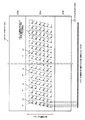
図3は、インクジェットヘッドのノズル面の平面透視図である。また、図4は、インクジェットヘッドの下端領域の側面図である。 FIG. 3 is a plan perspective view of the nozzle surface of the inkjet head. FIG. 4 is a side view of the lower end region of the inkjet head.
なお、各インクジェットヘッド16C、16M、16Y、16Kの構成は共通しているので、ここではインクジェットヘッド16として、そのノズル面30(30C、30M、30Y、30K)の構成を説明する。
In addition, since the structure of each
同図に示すように、ノズル面30は、長方形状に形成され、その幅方向(メディア搬送方向)の中央部に一定幅を有するノズル形成領域30Aが形成され、そのノズル形成領域30Aを挟んでノズル保護領域30Bが対称に形成される。
As shown in the figure, the
ノズル形成領域30Aは、ノズルが形成される領域であり、その表面には所定の撥液処理が施されている(撥液膜が被覆されている)。
The
ここで、図3に示すように、本実施の形態のインクジェットヘッド16は、いわゆるマトリックスヘッドで構成され、ノズルNがノズル形成領域30Aに二次元マトリクス状に配置される。より具体的には、メディア12の搬送方向に対して所定角度傾斜した方向に複数のノズルNが一定ピッチで配置されたノズルの列が形成されるとともに、そのノズルの列がメディア12の搬送方向と直交する方向(ヘッドの長手方向)に一定ピッチで多数配列される。このようなノズルの配置構成とすることにより、ヘッドの長手方向(メディア12の搬送方向と直交する方向)に投影される実質的なノズルNの間隔を狭めることができ、ノズルNの高密度化を図ることができる。
Here, as shown in FIG. 3, the
なお、マトリックスヘッドでは、このヘッドの長手方向に投影されるノズルの列が実質的なノズル列とされる。 In the matrix head, the nozzle row projected in the longitudinal direction of the head is a substantial nozzle row.
ノズル形成領域30Aの両側に配置されるノズル保護領域30Bは、ノズル形成領域30Aを保護するための領域であり、ノズル形成領域30Aは、このノズル保護領域30Bから所定量退避して凹状に形成されている(0.2mm程度)。
The
なお、本実施の形態のインクジェットヘッド16は、ノズル形成領域30Aにのみ撥液処理が施される(ノズル保護領域30Bには撥液処理は施されない)。この場合、ノズル保護領域30Bに液体が付着すると、液体はノズル保護領域30Bに濡れ広がる。
In addition, the
また、本実施の形態のインクジェットヘッド16は、いわゆるピエゾ方式でノズルNからインクの液滴を吐出させる。すなわち、ノズル面30に形成された各ノズルNは、それぞれ圧力室Pに連通されており、この圧力室Pの壁面をピエゾ素子で振動させることにより、圧力室Pの容積を拡縮させて、ノズルNからインクの液滴を吐出させる。
In addition, the
なお、インクの吐出方式は、これに限らずサーマル方式で吐出させる構成とすることもできる。 The ink ejection method is not limited to this, and a thermal ejection method may be employed.
画像記録部10は、以上のように構成される。この画像記録部10において、メディア12は、前段の工程から搬送ドラム26を介して画像記録ドラム14に受け渡され、画像記録ドラム14の周面に吸着保持されて回転搬送される。そして、その搬送過程で各インクジェットヘッド16C、16M、16Y、16Kの下を通過し、その通過時に各インクジェットヘッド16C、16M、16Y、16Kから吐出されたインクの液滴が記録面に打滴されて、記録面にカラー画像が形成される。画像が記録されたメディア12は、画像記録ドラム14から搬送ドラム28に受け渡され、後段の工程へと搬送される。
The
さて、以上のように構成される画像記録部10において、各インクジェットヘッド16C、16M、16Y、16Kは、図2に示すように、ヘッド支持フレーム40に取り付けられて、画像記録ドラム14の周囲に配置される。
In the
ヘッド支持フレーム40は、画像記録ドラム14の回転軸18と直交して設けられた一対のサイドプレート42L、42Rと、その一対のサイドプレート42L、42Rを上端部で連結する連結フレーム44とで構成されている。
The
一対のサイドプレート42L、42Rは、板状に形成されており、画像記録ドラム14を挟んで互いに対向するように配置されている。この一対のサイドプレート42L、42Rの内側には、各インクジェットヘッド16C、16M、16Y、16Kを取り付けるための取付部46C、46M、46Y、46Kが設けられている(図2では、便宜上、取付部46Yのみ図示)。
The pair of
取付部46C、46M、46Y、46Kは、画像記録ドラム14の回転軸18を中心とした同心円上に一定の間隔をもって放射状に配置されている。各インクジェットヘッド16C、16M、16Y、16Kは、その両端に形成された被取付部48C、48M、48Y、48K(図2では、便宜上、被取付部48Yのみ図示)を取付部46C、46M、46Y、46Kに固定することにより、ヘッド支持フレーム40に取り付けられる。そして、このヘッド支持フレーム40に取り付けられることにより、各インクジェットヘッド16C、16M、16Y、16Kが、画像記録ドラム14の回転軸18を中心とした同心円上に一定の間隔をもって放射状に配置される。
The mounting
ヘッド支持フレーム40は、図示しないガイドレールにガイドされて、画像記録ドラム14の回転軸18と平行にスライド移動自在に設けられている。そして、図示しないリニア駆動機構(たとえば、送りネジ機構など)に駆動されて、図2に実線で示す「画像記録位置」と図2に破線で示す「メンテナンス位置」との間を移動する。
The
各インクジェットヘッド16C、16M、16Y、16Kは、ヘッド支持フレーム40を画像記録位置に位置させると、画像記録ドラム14の周囲に配置され、画像記録可能な状態になる。
Each of the inkjet heads 16C, 16M, 16Y, and 16K is disposed around the
メンテナンス位置は、各インクジェットヘッド16C、16M、16Y、16Kが画像記録ドラム14から退避する位置に設定される。このメンテナンス位置には、各インクジェットヘッド16C、16M、16Y、16Kを保湿するための保湿ユニット50が設けられる。
The maintenance position is set to a position where each
保湿ユニット50には、各インクジェットヘッド16C、16M、16Y、16Kのノズル面を覆うキャップ52C、52M、52Y、52K(図2では、便宜上、キャップ52Yのみ図示)が備えられている。装置を長時間停止する場合などは、このキャップ52C、52M、52Y、52Kでノズル面が覆われる。これにより、乾燥による不吐出が防止される。
The
なお、このキャップ52C、52M、52Y、52Kには、図示しない加圧・吸引機構が備えられており、ノズル内を加圧・吸引できるように構成されている。
The
また、このキャップ52C、52M、52Y、52Kには、図示しない洗浄液供給機構が備えられており、内部に洗浄液を供給できるように構成されている。
The
キャップ52C、52M、52Y、52Kの下方位置には廃液トレイ54が配置されている。キャップ52C、52M、52Y、52Kに供給された洗浄液は、この廃液トレイ54に廃棄され、廃液回収配管56を介して廃液タンク58に回収される。
A
画像記録位置とメンテナンス位置との間には、各インクジェットヘッド16C、16M、16Y、16Kのノズル面30C、30M、30Y、30Kを清掃するためのノズル面清掃装置60が設けられている。各インクジェットヘッド16C、16M、16Y、16Kは、メンテナンス位置から画像記録位置に移動する過程で、このノズル面清掃装置60によってノズル面30C、30M、30Y、30Kが清掃される。
Between the image recording position and the maintenance position, a nozzle
以下、このノズル面清掃装置60の構成について説明する。
Hereinafter, the configuration of the nozzle
≪ノズル面清掃装置の構成≫
≪第1の実施の形態≫
図2に示すように、ノズル面清掃装置60は、洗浄液付与装置62とノズル面払拭装置64とを備えて構成されている。
≪Configuration of nozzle surface cleaning device≫
<< First Embodiment >>
As shown in FIG. 2, the nozzle
洗浄液付与装置62は、メンテナンス位置から画像記録位置に向かって移動する各インクジェットヘッド16C、16M、16Y、16Kのノズル面30C、30M、30Y、30Kに洗浄液を付与する。
The cleaning liquid applying
ノズル面払拭装置64は、洗浄液が付与された各インクジェットヘッド16C、16M、16Y、16Kのノズル面30C、30M、30Y、30Kに払拭ウェブを押圧当接させて、ノズル面30C、30M、30Y、30Kを払拭する。
The nozzle
洗浄液付与装置62とノズル面払拭装置64は、ヘッド支持フレーム40の移動経路上に配置される。この際、洗浄液付与装置62がノズル面払拭装置64に対してメンテナンス位置側に配置される。これにより、各インクジェットヘッド16C、16M、16Y、16Kをメンテナンス位置から画像記録位置に移動させた際、洗浄液の付与後に払拭ウェブでノズル面30C、30M、30Y、30Kを払拭することができる。
The cleaning liquid applying
なお、この配置は逆にすることもできる。すなわち、ノズル面払拭装置64をメンテナンス位置側に配置することもできる。この場合、各インクジェットヘッド16C、16M、16Y、16Kを画像記録位置からメンテナンス位置に移動させる過程でヘッドのノズル面30C、30M、30Y、30Kに洗浄液を付与し、その後、払拭ウェブでノズル面30C、30M、30Y、30Kを払拭する。
This arrangement can also be reversed. That is, the nozzle
≪洗浄液付与装置の構成≫
図5は、洗浄液付与装置をメンテナンス位置側から見た側面図である。
≪Configuration of cleaning liquid application device≫
FIG. 5 is a side view of the cleaning liquid application device viewed from the maintenance position side.
洗浄液付与装置62は、各インクジェットヘッド16C、16M、16Y、16Kに対応して設けられた洗浄液付与ユニット70C、70M、70Y、70Kと、その洗浄液付与ユニット70C、70M、70Y、70Kが搭載されるベース72とで構成され、保湿ユニット50に備えられた廃液トレイ54の内側に設置される(図2参照)。
The cleaning
〈ベースの構成〉
ベース72は、水平に設置されており、図示しない昇降装置によって昇降自在に設けられている。このベース72の上面部分には、洗浄液付与ユニット取付部72C、72M、72Y、72Kが形成されている。各洗浄液付与ユニット70C、70M、70Y、70Kは、このベース72に形成された洗浄液付与ユニット取付部72C、72M、72Y、72Kにボルト等で固定されて、所定位置に取り付けられる。そして、このベース72に取り付けられることにより、各洗浄液付与ユニット70C、70M、70Y、70Kは、対応するインクジェットヘッド16C、16M、16Y、16Kの移動経路上に配置される(画像記録位置からメンテナンス位置への移動経路上に配置される。)。
<Base configuration>
The
〈洗浄液付与ユニットの構成〉
次に、洗浄液付与ユニット70C、70M、70Y、70Kの構成について説明する。
<Configuration of cleaning liquid application unit>
Next, the configuration of the cleaning
なお、各洗浄液付与ユニット70C、70M、70Y、70Kの基本構成は共通しているので、ここでは洗浄液付与ユニット70として、その構成を説明する。
Since the basic configuration of each of the cleaning
図6、図7は、それぞれ洗浄液付与ユニットの正面図と側面図である。 6 and 7 are a front view and a side view of the cleaning liquid application unit, respectively.
同図に示すように、洗浄液付与ユニット70は、ノズル面30に洗浄液を付与する洗浄液付与ヘッド74と、ノズル面30から落ちる洗浄液を回収する洗浄液回収皿76とを備えて構成される。
As shown in the figure, the cleaning
洗浄液回収皿76は、上部が開口した矩形の箱状に形成されている。洗浄液付与ヘッド74は、この洗浄液回収皿76の内部に垂直に立設される。
The cleaning
洗浄液付与ヘッド74は、上面が傾斜した四角いブロック状に形成されており、その上部に傾斜した洗浄液保持面74Aを有している。この洗浄液保持面74Aは、清掃対象とするヘッドのノズル面30と同じ傾斜角度で形成されており、ノズル面30の幅(メディア搬送方向の幅)よりも若干広い幅をもって形成されている。
The cleaning
洗浄液保持面74Aの上部近傍には、洗浄液噴出口78が形成されており、この洗浄液噴出口78から洗浄液が流れ出る。洗浄液噴出口78から流れ出た洗浄液は、傾斜した洗浄液保持面74Aを流れ落ちる。これにより、洗浄液保持面74Aの上に洗浄液の層(膜)が形成される。インクジェットヘッド16は、この洗浄液保持面74Aの上に形成される洗浄液の層にノズル面30を接触させることにより、ノズル面30に洗浄液が付与される。
A cleaning
洗浄液付与ヘッド74の内部には、洗浄液噴出口78に連通する供給流路80が形成されている。この供給流路80は、洗浄液回収皿76に形成された連通流路76Aに連通されており、連通流路76Aは、洗浄液回収皿76に形成された洗浄液供給口76Bに連通されている。洗浄液付与ヘッド74は、この洗浄液供給口76Bに洗浄液が供給されることにより、洗浄液噴出口78から洗浄液が流れ出る。
Inside the cleaning
洗浄液は、洗浄液タンク(図示せず)から供給される。洗浄液供給口76Bには、この洗浄液タンクに接続された配管(図示せず)が接続される。この配管には洗浄液供給ポンプ(図示せず)及びバルブ(図示せず)が設けられ、このバルブを開けて、洗浄液供給ポンプを駆動することにより、洗浄液タンクから洗浄液付与ヘッド74に洗浄液が供給される。
The cleaning liquid is supplied from a cleaning liquid tank (not shown). A pipe (not shown) connected to the cleaning liquid tank is connected to the cleaning liquid supply port 76B. This pipe is provided with a cleaning liquid supply pump (not shown) and a valve (not shown). By opening this valve and driving the cleaning liquid supply pump, the cleaning liquid is supplied from the cleaning liquid tank to the cleaning
洗浄液回収皿76は、上記のように上部が開口した矩形の箱状に形成されている。この洗浄液回収皿76の底部は、傾斜して形成されており、その傾斜方向の下端部に回収穴88が形成されている。この回収穴88は、洗浄液回収皿76の内部に形成された回収流路76Cを介して、洗浄液回収皿76の側面部に形成された洗浄液排出口76Dに連通されている。
The cleaning
洗浄液付与ヘッド74の洗浄液噴出口78から噴出させた洗浄液は、洗浄液保持面74Aから流れ落ちて洗浄液回収皿76に回収される。この洗浄液回収皿76で回収された洗浄液は、ノズル面払拭装置64へと導かれ、廃液のフラッシングに供される。この点については、のちに詳述する。
The cleaning liquid ejected from the cleaning
洗浄液付与ユニット70(70C、70M、70Y、70K)は、以上のように構成される。そして、この洗浄液付与ユニット70C、70M、70Y、70Kが、ベース72に形成された洗浄液付与ユニット取付部72C、72M、72Y、72Kに取り付けられることにより、洗浄液付与装置62が構成される。
The cleaning liquid application unit 70 (70C, 70M, 70Y, 70K) is configured as described above. The cleaning
なお、洗浄液付与装置62の動作は、図示しない制御装置によって制御される。制御装置は、昇降装置等の駆動を制御して、洗浄液付与装置62による洗浄液の付与動作を制御する。
The operation of the cleaning liquid applying
また、洗浄液としては、たとえば、ジエチレンモノブチルエーテルを主成分とする洗浄液が用いられる。この種の洗浄液をノズル面30に付与することで、ノズル面30に付着したインク由来の固着物を溶解し除去しやすくすることができる。
As the cleaning liquid, for example, a cleaning liquid mainly composed of diethylene monobutyl ether is used. By applying this type of cleaning liquid to the
〈洗浄液付与装置の作用〉
次に、以上のように構成された洗浄液付与装置62による洗浄液の付与動作について説明する。
<Operation of cleaning liquid applicator>
Next, the operation of applying the cleaning liquid by the cleaning
洗浄液付与装置62は、インクジェットヘッド16(16C、16M、16Y、16K)がメンテナンス位置から画像記録位置に移動する過程でヘッドのノズル面30(30C、30M、30Y、30K)に洗浄液を付与する。具体的には、次のように洗浄液を付与する。
The cleaning liquid applying
洗浄液付与装置62は、全体が昇降自在に設けられている。清掃時以外、洗浄液付与装置62は、所定の待機位置に位置している。清掃時、洗浄液付与装置62は、待機位置から所定量上昇して、所定の作動位置に移動する。
The entire cleaning
洗浄液付与装置62が、作動位置に移動すると、各洗浄液付与ユニット70C、70M、70Y、70Kが、所定の洗浄液付与位置にセットされる。これにより、各洗浄液付与ユニット70C、70M、70Y、70Kに備えられた洗浄液付与ヘッド74によって各ヘッドのノズル面30C、30M、30Y、30Kに洗浄液を付与することが可能になる。すなわち、各洗浄液付与ユニット70C、70M、70Y、70Kが、洗浄液付与位置にセットされると、洗浄液付与ヘッド74の洗浄液保持面74Aを流れる洗浄液が、ノズル面30C、30M、30Y、30Kに接触する位置(洗浄液保持面74Aとノズル面30C、30M、30Y、30Kとのギャップが所定範囲になる位置)に各洗浄液付与ユニット70C、70M、70Y、70Kがセットされる。
When the cleaning
各洗浄液付与ユニット70C、70M、70Y、70Kが、所定の洗浄液付与位置にセットされると、制御装置は、リニア駆動機構を駆動して、ヘッド支持フレーム40をメンテナンス位置から画像記録位置に向けて所定の移動速度で移動させる。
When each of the cleaning
その一方で制御装置は、各インクジェットヘッド16C、16M、16Y、16Kが、洗浄液付与ユニット70C、70M、70Y、70Kの洗浄液付与ヘッド74に到達するタイミングに合わせて、洗浄液供給ポンプを駆動する。これにより、各洗浄液付与ユニット70C、70M、70Y、70Kに備えられた洗浄液付与ヘッド74の洗浄液噴出口78から洗浄液が所定の流量で流れ出る。洗浄液噴出口78から流れ出た洗浄液は、洗浄液保持面74Aを流れ落ちる。これにより、洗浄液保持面74Aの上に洗浄液の層(膜)が形成される。
On the other hand, the control device drives the cleaning liquid supply pump in accordance with the timing at which each
画像記録位置に向かうインクジェットヘッド16C、16M、16Y、16Kは、この洗浄液付与ヘッド74を通過する際、そのノズル面30C、30M、30Y、30Kが、洗浄液付与ヘッド74の洗浄液保持面74Aの上に形成された洗浄液の層に接触する。これにより、ノズル面30C、30M、30Y、30Kに洗浄液が付与される。
When the inkjet heads 16C, 16M, 16Y, and 16K heading toward the image recording position pass through the cleaning
≪ノズル面払拭装置の構成≫
図8は、ノズル面払拭装置をメンテナンス位置側から見た側面図である。
≪Configuration of nozzle surface wiping device≫
FIG. 8 is a side view of the nozzle surface wiping device as viewed from the maintenance position side.
同図に示すように、ノズル面払拭装置64は、各インクジェットヘッド16C、16M、16Y、16Kに対応して設けられた払拭ユニット100C、100M、100Y、100Kと、その払拭ユニット100C、100M、100Y、100Kがセットされる払拭装置本体フレーム102とで構成されている。
As shown in the figure, the nozzle
〈払拭装置本体フレームの構成〉
払拭装置本体フレーム102は、水平に設置されており、図示しない昇降装置によって昇降自在に設けられている。この払拭装置本体フレーム102は、上端部が開口した箱状に形成されており、その内部に各払拭ユニット100C、100M、100Y、100Kを装着するための払拭ユニット装着部104C、104M、104Y、104Kが形成されている。
<Configuration of wiping device body frame>
The wiping device
払拭ユニット装着部104C、104M、104Y、104Kは、払拭ユニット100C、100M、100Y、100Kを収容可能な空間として形成されており、上部が開口して形成されている。各払拭ユニット100C、100M、100Y、100Kは、各払拭ユニット装着部104C、104M、104Y、104Kの上部開口部から鉛直下向きに差し込むことにより、各払拭ユニット装着部104C、104M、104Y、104Kにセットされる。
The wiping
なお、各払拭ユニット装着部104C、104M、104Y、104Kには、図示しないロック機構が備えられ、装着された払拭ユニット100C、100M、100Y、100Kをロックできるように構成される。ロック機構は、たとえば、払拭ユニット100C、100M、100Y、100Kを払拭ユニット装着部104C、104M、104Y、104Kに差し込むと、自動的に作動するように構成される。
Each wiping
〈払拭ユニットの構成〉
次に、払拭ユニット100C、100M、100Y、100Kの構成について説明する。
<Configuration of wiping unit>
Next, the configuration of the wiping
なお、各払拭ユニット100C、100M、100Y、100Kの基本構成は共通しているので、ここでは払拭ユニット100として、その構成を説明する。払拭ユニット装着部104C、104M、104Y、104Kについても同様であり、払拭ユニット装着部104として説明する。
In addition, since the basic structure of each wiping
図9は払拭ユニットの平面図、図10は払拭ユニットを画像記録位置側から見た側面図、図11は払拭ユニットの側面部分断面図、図12は払拭ユニットの正面部分断面図、図13は払拭ユニットの背面図である。 9 is a plan view of the wiping unit, FIG. 10 is a side view of the wiping unit viewed from the image recording position side, FIG. 11 is a side sectional view of the wiping unit, FIG. 12 is a front sectional view of the wiping unit, and FIG. It is a rear view of a wiping unit.
図9〜図13に示すように、払拭ユニット100は、傾斜して設置された押圧ローラ118に帯状に形成された払拭ウェブ110を巻き掛け、この押圧ローラ118に巻き掛けた払拭ウェブ110をインクジェットヘッドのノズル面に押圧当接させることにより、インクジェットヘッドのノズル面を払拭清掃する。
As shown in FIGS. 9 to 13, the
この払拭ユニット100は、ケース112と、帯状に形成された払拭ウェブ110を繰り出す繰出軸114と、払拭ウェブ110を巻き取る巻取軸116と、繰出軸114から繰り出された払拭ウェブ110が押圧ローラ118に巻き掛けられるようにガイドする前段ガイド120と、押圧ローラ118に巻き掛けられた払拭ウェブ110が巻取軸116に巻き取られるようにガイドする後段ガイド122と、払拭ウェブ110を搬送するグリッドローラ(駆動ローラ)124とを備えて構成される。
The
ケース112は、ケース本体126と蓋128とで構成されている。ケース本体126は、縦方向に長い四角い箱状に形成されており、上端部と前面部とが開口して形成されている。蓋128は、ヒンジ130を介して、ケース本体126の前面部に取り付けられている。ケース本体126は、この蓋128によって前面部が開閉される。
The
なお、蓋128には弾性変形可能なロック爪132が設けられており、このロック爪132をケース本体126に形成された爪受部134に弾性変形させて係合させることにより、ケース本体126に固定される。
The
繰出軸114は、円柱状に形成され、その基端部をケース本体126に設けられた軸支持部136に固定(片持ち支持)されて、ケース本体126の内部に水平に設置される。この繰出軸114には繰出コア138が着脱自在に装着される。なお、繰出軸114は、繰出コア138の長さよりも若干短く形成される。したがって、繰出コア138が装着されると、繰出軸114は、繰出コア138の内周部に退避する。
The feeding
繰出コア138は、円筒状に形成される。帯状に形成された払拭ウェブ110は、この繰出コア138にロール状に巻回される。
The
繰出コア138は、その内周部に繰出軸114を挿入して、繰出軸114に嵌めることにより、繰出軸114に装着される。繰出軸114に装着された繰出コア138は、繰出軸114の周りを回転して、回転自在に支持される。
The
ここで、図11に示すように、ケース112の蓋128には、繰出軸114の設置位置に対応して繰出コア押え駒139が設けられている。蓋128が閉じられると、この繰出コア押え駒139が、繰出軸114に装着された繰出コア138の端面を軸方向に押圧し、繰出コア138にフリクションを与える。
Here, as shown in FIG. 11, the
この繰出コア押え駒139は、軸部139Aと、その軸部139Aに摺動自在に設けられた押圧部139Bと、押圧部139Bを軸方向に付勢するバネ139Cとで構成される。
The feeding
軸部139Aは、円柱状に形成され、蓋128の内面に垂直に取り付けられる。この軸部139Aは、蓋128を閉めたときに、繰出軸114と同軸上に位置するように配置される。
The
押圧部139Bは、ボス139B1とフランジ部139B2とで構成される。ボス139B1は、円筒状に形成され、その外周は、繰出コア138の内径とほぼ同じに形成され、繰出コア138の内周部に挿入可能に形成される。また、その内径は軸部139Aの外径とほぼ同じに形成され、軸部139Aに沿って摺動可能に形成される。フランジ部139B2は、ボス139B1の基端部に一体的に形成され、外周方向に張り出して形成される。このフランジ部139B2の基端部の内径は拡大して形成されており、この拡大して形成されたフランジ部139B2の内周部にバネ139Cが収容される。押圧部139Bは、このバネ139Cによって軸部139Aの先端方向に向けて付勢される。
The pressing portion 139B includes a boss 139B1 and a flange portion 139B2. The
なお、軸部139Aの先端には、フランジ部が形成され、このフランジ部により、押圧部139Bの抜けが防止される。
A flange portion is formed at the tip of the
以上のように構成された繰出コア押え駒139は、ケース112の蓋128を閉じると、押圧部139Bのボス139B1が、繰出コア138の内周部に嵌入するとともに、フランジ部139B2が、繰出コア138の端面に当接し、バネ139Cの力によって、繰出コア138を軸方向に押圧する。これにより、繰出コア138は、繰出コア押え駒139とフランジ114Aとの間で押圧挟持され、回転に際してフリクションが与えられる。
When the
なお、払拭ウェブ110には、たとえば、PET、PE、NY等の極微細繊維を用いた編み又は織りからなるシートが用いられ、払拭対象とするヘッドのノズル面の幅に対応した幅を有する帯状に形成される。
For the wiping
巻取軸116は、繰出軸114の下方位置に水平に配設される。すなわち、巻取軸116と繰出軸114とは、上下に並列して配置される。
The winding
この巻取軸116は、図11に示すように、主軸116Aと、その主軸116Aの周りを周方向に回転自在に設けられた滑り軸116Bと、主軸116Aと滑り軸116Bとを連結するトルクリミッタ116Cとで構成され、一定以上の負荷(トルク)が掛かると、主軸116Aに対して滑り軸116Bが滑るように構成されている。
As shown in FIG. 11, the take-up
主軸116Aは、円柱の棒状に形成され、その基端部近傍をケース本体126に設けられた軸受部140に回動自在に支持される。
The
滑り軸116Bは、円筒状に形成され、主軸116Aの外周部を周方向に回転自在に設けられる。
The sliding shaft 116B is formed in a cylindrical shape, and is provided so that the outer peripheral portion of the
トルクリミッタ116Cは、滑り軸116Bの先端内周部に配置され、主軸116Aと滑り軸116Bと連結する。このトルクリミッタ116Cは、同軸上に配置された入力側回転体(図示せず)と出力側回転体(図示せず)とを備えており、入力側回転体に対して出力側回転体に一定以上の負荷(トルク)が掛かると、その入力側回転体と出力側回転体との間で滑るように構成されている。トルクリミッタ116Cは、入力側回転体を主軸116Aに接続(たとえば、キーとキー溝、あるいは、ボスとボス孔とにより回転伝達可能に接続、又は、一体的に固定して回転伝達可能に接続)され、出力側回転体を滑り軸116Bに接続(たとえば、キーとキー溝、あるいは、ボスとボス孔とにより回転伝達可能に接続、又は、一体的に固定して回転伝達可能に接続)されて、主軸116Aと滑り軸116Bとを回転伝達可能に連結する。これにより、滑り軸116Bに一定以上の負荷がかかると、主軸116Aに対して滑り軸116Bが滑るように機能する。
The torque limiter 116C is disposed on the inner periphery of the tip end of the sliding shaft 116B and is connected to the
以上の構成の巻取軸116は、滑り軸116Bに作用する負荷(トルク)が一定範囲内であれば、滑りは発生せず、滑り軸116Bが主軸116Aと共に一体的に回転する。一方、滑り軸116Bに作用する負荷(トルク)が一定範囲を超えると、滑り軸116Bと主軸116Aとの間で滑りが生じ、主軸116Aに無理な負荷が掛かるのを防止することができる。
When the load (torque) acting on the sliding shaft 116B is within a certain range, the winding
この巻取軸116には、繰出コア138から繰り出された払拭ウェブ110を巻き取る巻取コア142が装着される。
A winding
巻取コア142の構成は、繰出コア138の構成とほぼ同じである。すなわち、円筒状に形成される。繰出コア138に巻回された払拭ウェブ110の先端は、この巻取コア142に固定される。
The configuration of the winding
巻取コア142は、その内周部に繰出軸114を嵌めることにより、繰出軸114に装着される。
The winding
ここで、図11に示すように、巻取コア142は、その内周部にキー溝142Cが形成されている。一方、巻取軸116の外周(滑り軸116Bの外周)には、そのキー溝142Cに嵌合するキー116Dが形成されている。巻取コア142の装着時には、この巻取軸116に形成されたキー116Dを巻取コア142に形成された形成されたキー溝142Cに嵌めて装着する。これにより、巻取軸116の回転を巻取コア142に伝達可能に装着される。
Here, as shown in FIG. 11, the winding
また、図11に示すように、ケース112の蓋128の内側には、巻取軸116の設置位置に対応してガイド板143が設けられる。このガイド板143は、払拭ウェブ110の巻取径に対応した径の円盤状に形成され、蓋128が閉じられると、巻取軸116の先端に配置される。
As shown in FIG. 11, a
また、図11に示すように、巻取軸116の基端部には、ガイド板143とほぼ同径のフランジ116Eが形成される。巻取コア142は、巻取軸116に装着されて、ケース112の蓋128が閉じられると、このフランジ116Eとガイド板143との間に配置される。巻取コア142に巻き取られる払拭ウェブ110は、このフランジ116Eとガイド板143とによって両縁部をガイドされながら、巻取コア142に巻き取られる。
As shown in FIG. 11, a
巻取軸116の主軸116Aは、その基端部がケース本体126の外側に突出して設けられており、その突出した基端部に巻取軸ギア158が取り付けられる。巻取軸116(主軸116A)は、この巻取軸ギア158が回転駆動されることにより回転する。なお、この巻取軸116の駆動機構については後述する。
The
押圧ローラ118は、繰出軸114の上方に配置されており(本例では、押圧ローラ118と繰出軸114と巻取軸116とが同一直線上に配置されている。)、水平面に対して所定角度傾斜して配置されている。すなわち、この押圧ローラ118は、払拭ウェブ110をインクジェットヘッド16のノズル面30に押圧当接させるものであるため、払拭対象とするインクジェットヘッド16のノズル面30の傾きに合わせて傾けて配置されている(ノズル面と平行になるように配置されている)。
The
また、押圧ローラ118は、払拭対象とするインクジェットヘッド16のノズル面30の断面形状に倣って中央部が拡径して形成されている(図14参照)。すなわち、本実施の形態のインクジェットヘッド16は、ノズル面30の中央部(ノズル形成領域30A)が凹状に退避して形成されているので、この凹状に形成されたノズル面30に対応して中央部が凸状に突出して形成されている。より具体的には、凹状に退避したノズル形成領域30Aに対応する領域(払拭時に当接する領域)が、その退避量に対応して突出(拡大)して形成されている。これにより、凹状に退避して形成されたノズル形成領域30Aに適切に払拭ウェブ110を当接させることができる。
Further, the
押圧ローラ118は、その両端部に軸部118L、118Rが突出して設けられており、この軸部118L、118Rを一対の軸支持部146L、146Rに軸支されて、回動自在かつ揺動自在に支持されている。
The
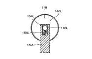
図14は、押圧ローラ118の軸部を支持する軸支持部の構成を示す正面部分断面図である。また、図15は、図14の15−15断面図である。
FIG. 14 is a front partial cross-sectional view showing the configuration of the shaft support portion that supports the shaft portion of the
同図に示すように、軸支持部146L、146Rは、水平に設けられた昇降ステージ170の上に設けられている。この軸支持部146L、146Rは、ともに昇降ステージ170に垂直に立設された柱部150L、150Rと、その柱部150L、150Rの先端に屈曲して設けられた支持部152L、152Rとで構成されている。
As shown in the figure, the
支持部152L、152Rは、押圧ローラ118の軸と直交するように設けられており、その内側に凹部154L、154Rが形成されている。凹部154L、154Rは、押圧ローラ118の軸部118L、118Rの幅とほぼ同じ幅を有する長方形状に形成されており、清掃の対象とするインクジェットヘッドのノズル面に対して直交して形成されている(図15参照)。押圧ローラ118は、その両端の軸部118L、118Rが、この支持部152L、152Rの凹部154L、154Rに遊嵌されている。この結果、押圧ローラ118は、清掃の対象とするインクジェットヘッドのノズル面に対して直交する面内で揺動自在に支持される。
The
凹部154L、154Rの内側には、バネ156L、156Rが収容されており、凹部154L、154R内に遊嵌された押圧ローラ118の軸部118L、118Rは、このバネ156L、156Rによって上方に付勢されている。これにより、清掃の対象とするインクジェットヘッドのノズル面に倣って、押圧ローラ118の周面をノズル面に密着させることができる。
前段ガイド120は、第1前段ガイド160と、第2前段ガイド162とで構成され、繰出軸114から繰り出された払拭ウェブ110が、傾斜して設置された押圧ローラ118に巻き掛けられるようにガイドする。
The
一方、後段ガイド122は、第1後段ガイド164と、第2後段ガイド166とで構成され、傾斜して設置された押圧ローラ118に巻き掛けられた払拭ウェブ110が、水平に設置された巻取軸116に巻き取れるようにガイドする。
On the other hand, the
この前段ガイド120と後段ガイド122は、押圧ローラ118を挟んで対称に配置されている。すなわち、第1前段ガイド160と第1後段ガイド164とが押圧ローラ118を挟んで対称に配置されるとともに、第2前段ガイド162と第2後段ガイド166とが押圧ローラ118を挟んで対称に配置されている。
The
第1前段ガイド160は、所定の幅を有する板状に形成されており、昇降ステージ170の上に垂直に立設されている。この第1前段ガイド160は、上縁部160Aが、払拭ウェブ110の巻き掛け部として形成されており、その表面が円弧状に形成されている。また、この上縁部160Aは、水平面に対して所定角度傾斜して形成されており、これにより、払拭ウェブ110の走行方向が変換される。
The first
第1後段ガイド164は、第1前段ガイド160と同じ構成である。すなわち、所定の幅を有する板状に形成されており、昇降ステージ170の上に垂直に立設されている。そして、その上縁部164Aが、払拭ウェブ110の巻き掛け部として形成され、円弧状に形成されるとともに、水平面に対して所定角度傾斜して形成されている。
The first
この第1前段ガイド160と第1後段ガイド164とが、押圧ローラ118を挟んで対称に配置されている。繰出軸114から繰り出された払拭ウェブ110は、第1前段ガイド160に巻き掛けられることにより、繰出軸114と直交する方向から押圧ローラ118と略直交する方向に方向転換される。また、後述する第2後段ガイド166に巻き掛けられた払拭ウェブ110は、第1後段ガイド164に巻き掛けられることにより、巻取軸116と直交する方向に方向転換される。
The first
第2前段ガイド162は、両端部にフランジ162L、162Rを有するガイドローラとして構成されている。この第2前段ガイド162は、第1前段ガイド160と押圧ローラ118との間に配置され、第1前段ガイド160に巻き掛けられた払拭ウェブ110が、押圧ローラ118に巻き掛けられるようにガイドする。すなわち、第1前段ガイド160によって押圧ローラ118と略直交する方向に方向転換された払拭ウェブ110が、押圧ローラ118と直交する方向に走行するように、払拭ウェブ110の走行方向を微調整する。また、両端のフランジ162L、162Rによって、払拭ウェブ110の斜行を防止する。
The second
この第2前段ガイド162は、一端をブラケット168Aに片持ち支持されて、所定角度傾斜して設けられている。ブラケット168Aは、図13及び図16に示すように、先端が屈曲したプレート状に形成されており、その基端部がケース本体126の背面上端部に固定されている。そして、そのケース本体126の上端部から上方に向けて垂直に突出して設けられている。第2前段ガイド162は、このブラケット168Aの先端の屈曲部に片持ち支持されて回動自在に支持されている。
The second
第2後段ガイド166は、第2前段ガイド162と同じ構成である。すなわち、両端部にフランジ166L、166Rを有するガイドローラとして構成され、一端をブラケット168Bに片持ち支持されて、所定角度傾斜して設けられている。ブラケット168Bは、先端が屈曲したプレート状に形成されており、その基端部がケース本体126の背面上端部に固定されている。第2後段ガイド166は、このブラケット168Bの先端の屈曲部に片持ち支持されて回動自在に支持されている。
The second
この第2後段ガイド166は、押圧ローラ118と第1後段ガイド164との間に配置され、押圧ローラ118に巻き掛けられた払拭ウェブ110が、第1後段ガイド164に巻き掛けられるようにガイドする。
The second
この第2前段ガイド162と第2後段ガイド166とが、押圧ローラ118を挟んで対称に配置されている。第1前段ガイド160によって押圧ローラ118と略直交する方向に方向転換された払拭ウェブ110は、第2前段ガイド162に巻き掛けられることにより、押圧ローラ118と直交する方向に走行するように、走行方向が微調整される。また、押圧ローラ118に巻き掛けられた払拭ウェブ110は、第1後段ガイド164に巻き掛けられるように、第2後段ガイド166によって走行方向が微調整される。そして、第1後段ガイド164に巻き掛けられることにより、巻取軸116と直交する方向に方向転換される。
The second
このように、前段ガイド120と後段ガイド122は、段階的に払拭ウェブ110の走行方向を切り換えることにより、払拭ウェブ110が、無理なく押圧ローラ118に巻き掛けられるようにガイドする。
In this way, the
このため、第1前段ガイド160の傾斜角度に比べて第2前段ガイド162の傾斜角度は押圧ローラ118の傾斜角度に近い角度となっており、同様に第1後段ガイド164の傾斜角度に比べて第2後段ガイド166の傾斜角度は押圧ローラ118の傾斜角度に近い角度となっている。
For this reason, the inclination angle of the second
ところで、上記のように、第1前段ガイド160と押圧ローラ118と第1後段ガイド164は、それぞれ昇降ステージ170の上に設けられている。この昇降ステージ170は、水平面に対して垂直方向に昇降移動自在に設けられている。
By the way, as described above, the first
図11に示すように、昇降ステージ170には、その下部にガイド軸172が一体的に取り付けられている。ガイド軸172は、昇降ステージ170の下面部から鉛直下向きに延びており、ケース本体126内に配置されたガイドブッシュ174に嵌合されている。ガイドブッシュ174は、支持部材176を介してケース本体126の内壁面に固定されており、ガイド軸172を水平面に対して垂直にガイドする。
As shown in FIG. 11, a
このように、第1前段ガイド160と押圧ローラ118と第1後段ガイド164が設けられた昇降ステージ170は、水平面に対して垂直に昇降自在に設けられている。このため、図17に示すように、この昇降ステージ170を昇降移動させることにより、第1前段ガイド160と押圧ローラ118と第1後段ガイド164とを、固定して設置された第2前段ガイド162と第2後段ガイド166に対して、進退移動させることができる。これにより、払拭ウェブ110の交換を簡単に行うことができる。
As described above, the elevating
すなわち、昇降ステージ170を下降させることにより、図17(b)に示すように、第1前段ガイド160と押圧ローラ118と第1後段ガイド164を、第2前段ガイド162と第2後段ガイド166とに対して下方へ退避させることができ、その間のスペースを大きく確保することができる。これにより、各部への払拭ウェブ110の巻き掛け作業を簡単に行うことができる。また、各部に払拭ウェブ110を巻き掛ける場合は、第1前段ガイド160と押圧ローラ118と第1後段ガイド164を下方に退避させた状態で、第1前段ガイド160と押圧ローラ118と第1後段ガイド164に払拭ウェブ110を巻き掛け、その後、昇降ステージ170を上昇させるだけで済む。すなわち、第1前段ガイド160と押圧ローラ118と第1後段ガイド164に払拭ウェブ110を巻き掛け、その後、昇降ステージ170を上昇させると、図17(a)に示すように、自動的に第2前段ガイド162と第2後段ガイド166とに払拭ウェブ110が巻き掛けられる。
That is, by lowering the elevating
このように、第1前段ガイド160と押圧ローラ118と第1後段ガイド164を、第2前段ガイド162と第2後段ガイド166に対して、進退可能とすることにより、払拭ウェブ110の交換作業を簡単に行うことができる。
As described above, the first
なお、第1前段ガイド160と押圧ローラ118と第1後段ガイド164は、使用に際して、所定の使用位置(図17(a)の位置)に位置させる必要があるが、この第1前段ガイド160と押圧ローラ118と第1後段ガイド164の使用位置への移動は、払拭装置本体フレーム102への払拭ユニット100の装着に連動して行われる。
The first
ここで、この連動機構について説明する。図11及び図13に示すように、第1前段ガイド160と押圧ローラ118と第1後段ガイド164とが設けられた昇降ステージ170には、背部に昇降レバー(係合部)178が設けられている。この昇降レバー178は、ケース本体126の背面に形成された切欠き部180を介してケース本体126の背面から突出して設けられている。昇降ステージ170は、この昇降レバー178をスライドさせることにより、昇降移動する。
Here, this interlocking mechanism will be described. As shown in FIGS. 11 and 13, the elevating
一方、図18に示すように、払拭ユニット100がセットされる払拭装置本体フレーム102の払拭ユニット装着部104(104C、104M、104Y、104K)には、その内側にピン(被係合部)182が突出して設けられている。このピン182は、払拭ユニット100が、払拭ユニット装着部104に装着されると、払拭ユニット100に設けられた昇降レバー178に係合するように設けられている。
On the other hand, as shown in FIG. 18, the wiping unit mounting portion 104 (104C, 104M, 104Y, 104K) of the wiping device
以上の構成により、図18に示すように、払拭ユニット100を払拭装置本体フレーム102の払拭ユニット装着部104に差し込むと、昇降レバー178がピン182に係合し、強制的に所定位置まで上昇させられる。この結果、第1前段ガイド160と押圧ローラ118と第1後段ガイド164とが、所定の使用位置に位置決めされる。
With the above configuration, as shown in FIG. 18, when the
このように、第1前段ガイド160と押圧ローラ118と第1後段ガイド164の使用位置への移動は、払拭装置本体フレーム102への払拭ユニット100の装着に連動して行われる。
Thus, the movement of the first
グリッドローラ124は、第1後段ガイド164の下方位置であって、ケース本体126の底部近傍に配置されている。このグリッドローラ124は、第1後段ガイド164によって巻取軸116と直交する方向に方向転換された払拭ウェブ110が、巻取軸116に巻き取られるように駆動力を与えながらガイドする。
The
グリッドローラ124は、巻取軸116と平行(=水平面と平行)に設けられており、その回転軸をケース本体126に設けられた軸受部184に回動自在に支持されている。回転軸は、基端部がケース本体126の外側に突出して設けられており、その突出した基端部には、グリッドローラギア186が固着されている。グリッドローラ124は、このグリッドローラギア186が回転駆動されることにより回転する。
The
ここで、このグリッドローラ124を含む払拭ユニット100の駆動機構について説明する。
Here, a driving mechanism of the
本実施の形態の払拭ユニット100では、巻取軸116を回転駆動するとともに、グリッドローラ124を回転駆動することにより、払拭ウェブ110を繰出軸114から巻取軸116に向けて走行させる。
In the
上記のように、巻取軸116(巻取軸116を構成する主軸116A)には、巻取軸ギア158が取り付けられている。一方、グリッドローラ124には、グリッドローラギア186が取り付けられている。この巻取軸ギア158とグリッドローラギア186は、図13に示すように、回転伝達ギア188に噛み合わされている。
As described above, the take-up
回転伝達ギア188は、その回転軸が水平に設けられており、ケース本体126に設けられた軸受部190に回動自在に支持されている。巻取軸ギア158とグリッドローラギア186は、この回転伝達ギア188を回転させることにより、同じ方向に回転する。そして、この巻取軸ギア158とグリッドローラギア186とが回転することにより、巻取軸116とグリッドローラ124とが回転する。
The
ここで、本例のノズル面払拭装置64では、巻取軸ギア158とグリッドローラギア186に径の異なるギア(歯数の異なるギア)を用いており、巻取軸116とグリッドローラ124とが異なる速度で回転するように設定されている。すなわち、本例のノズル面払拭装置64では、払拭ウェブ110を弛みなく搬送できるようにするために、グリッドローラ124で払拭ウェブ110を送る速度よりも巻取コア142で払拭ウェブ110を巻き取る速度の方が速くなるように、巻取軸116の回転速度とグリッドローラ124の回転速度が設定されている。これにより、弛みなく安定して払拭ウェブ110を巻き取ることができる。
Here, in the nozzle
具体的には、巻取軸116に装着された巻取コア142の周速度V1が、グリッドローラ124の周速度V2よりも大きくなるように(V1>V2)、巻取軸116の回転速度とグリッドローラ124の回転速度が設定され、それに基づき巻取軸ギア158とグリッドローラギア186とのギア比が設定される。
Specifically, the rotational speed of the winding
なお、実際に設定する回転速度については、実験等で最適な数値を求めて設定される。すなわち、両者の間にあまりに差を設けすぎると、磨耗、故障等の原因になるので、実験等により最適な速度を求めて設定される。 Note that the rotation speed that is actually set is set by obtaining an optimal numerical value through experiments or the like. That is, if there is too much difference between the two, it will cause wear, failure, etc., so an optimum speed is obtained by experimentation.
なお、このように巻取速度と送り速度に差を設けたとしても、本例のノズル面払拭装置64では、巻取軸116に滑り機構(トルクリミッタ116Cによる滑り機構)が備えられているので、巻取軸116やグリッドローラ124、モータ194等に過負荷を与えることなく、駆動することができる。
Even if a difference is provided between the winding speed and the feeding speed in this way, in the nozzle
巻取軸ギア158とグリッドローラギア186とを回転させる回転伝達ギア188は、払拭ユニット100を払拭装置本体フレーム102の払拭ユニット装着部104に装着すると、払拭ユニット装着部104内に設けられた駆動ギア192に噛み合わされる。
The
駆動ギア192は、モータ194の出力軸に取り付けられており、払拭ユニット100を払拭ユニット装着部104に装着した際、その回転伝達ギア188が歯合する位置に配置される。
The
モータ194は、たとえば、パルスモータで構成され、払拭ユニット装着部104の底部に取り付けられる。このモータ194の駆動は、図示しない制御装置によって制御される。
The
払拭ユニット100の駆動機構は以上のように構成される。
The drive mechanism of the
上記のように、払拭ユニット100を払拭装置本体フレーム102の払拭ユニット装着部104に装着すると、払拭ユニット100のケース112に設けられた回転伝達ギア188が、払拭ユニット装着部104に設けられた駆動ギア192に噛み合わされる(図18参照)。この状態でモータ194を駆動すると、そのモータ194の出力軸に取り付けられた駆動ギア192が回転し、その回転が回転伝達ギア188に伝達されて、回転伝達ギア188が回転する。
As described above, when the
回転伝達ギア188が回転すると、その回転伝達ギア188の回転が巻取軸ギア158とグリッドローラギア186とに伝達されて、巻取軸ギア158とグリッドローラギア186とが回転する。この結果、巻取軸116とグリッドローラ124とが回転する。そして、この巻取軸116とグリッドローラ124が回転することにより、繰出軸114に装着された繰出コア138から払拭ウェブ110が繰り出され、所定の走行経路を通って巻取軸116に装着された巻取コア142に巻き取られる。
When the
このように、払拭ユニット100を払拭ユニット装着部104に装着すると、回転伝達ギア188が駆動ギア192に噛み合わされて、巻取軸116とグリッドローラ124とを駆動することが可能になる。
As described above, when the
一方、払拭ユニット100を払拭ユニット装着部104に装着すると、図19及び図20に示すように、払拭ユニット装着部104に設けられたニップローラ200が、ケース本体126の底部に形成された開口部126Aを介してグリッドローラ124の外周部に押圧当接される。
On the other hand, when the
ニップローラ200は、グリッドローラ124とほぼ同じ幅で形成されており、外周部がゴム等の弾性体で被覆れている。このニップローラ200は、払拭ユニット装着部104に設置された廃液受け202に水平に取り付けられている。
The
廃液受け202は、上部が開口した矩形の箱状に形成されており、その上辺部にニップローラ200を支持する軸受部(図示せず)が設けられている。ニップローラ200は、この軸受部に軸支されて、廃液受け202に回動自在に支持される。
The
廃液受け202は、内側の底面部が傾斜して形成されており、その傾斜方向の下端部に廃液口206が形成されている。廃液口206には、図示しない配管を介して廃液タンク58に接続される。
The
払拭ウェブ110が装填された払拭ユニット100を払拭ユニット装着部104に装着すると、グリッドローラ124に巻き掛けられた払拭ウェブ110は、ニップローラ200とグリッドローラ124との間にニップされる。
When the
ニップローラ200とグリッドローラ124との間にニップされた払拭ウェブ110は、この状態でグリッドローラ124が回転駆動されることにより、巻取コア142に向けて送られる。
The wiping
ここで、このニップローラ200とグリッドローラ124とにニップされる払拭ウェブ110は、ノズル面を払拭した後の払拭ウェブ110であるため、洗浄液等が吸収されている。この払拭ウェブ110に吸収された液体は、グリッドローラ124とニップローラ200との間を通過することにより、払拭ウェブ110から除去され、廃液受け202で回収される。
Here, since the wiping
このように、ニップローラ200とグリッドローラ124とは、払拭ウェブ110の搬送手段として機能するとともに、払拭ウェブ110で吸収された液体(廃液)の除去手段としても機能する。これにより、巻取コア142に巻き取られた払拭ウェブ110から廃液が垂れ落ちて、周囲を汚染したり、装置を故障させたりするのを防止できる。
As described above, the
払拭ユニット100(100C、100M、100Y、100K)は、以上のように構成される。 The wiping unit 100 (100C, 100M, 100Y, 100K) is configured as described above.
ノズル面払拭装置64は、この払拭ユニット100C、100M、100Y、100Kが払拭装置本体フレーム102の払拭ユニット装着部104に装着されることにより構成される。
The nozzle
なお、ノズル面払拭装置64の動作は、図示しない制御装置によって制御される。制御装置は、昇降装置、モータ194等の駆動を制御して、ノズル面払拭装置64による付与動作を制御する。
The operation of the nozzle
〈払拭装置の作用〉
次に、以上のように構成された本実施の形態のノズル面払拭装置64の作用について説明する。
<Operation of wiping device>
Next, the operation of the nozzle
<払拭ウェブの装着>
まず、払拭ユニット100への払拭ウェブ110の装着方法について説明する。
<Installation of wiping web>
First, a method for attaching the wiping
払拭ウェブ110は、繰出コア138にロール状に巻回された状態で提供され、その先端は巻取コア142に固定される。
The wiping
まず、払拭ユニット100を払拭装置本体フレーム102から取り出し、ケース112の蓋128を開ける。蓋128を開けると、繰出軸114と巻取軸116とが露出するので、繰出軸114に繰出コア138を装着し、巻取軸116に巻取コア142を装着する。
First, the
この際、払拭ウェブ110を第1前段ガイド160、押圧ローラ118、第1後段ガイド164、グリッドローラ124に巻き掛けながら、繰出コア138と巻取コア142を装着する。
At this time, the
具体的には、まず、繰出コア138を繰出軸114に装着する。繰出コア138の装着は、繰出コア138を繰出軸114に嵌めることにより行われる。これにより、繰出コア138が、繰出軸114の周りを回動自在に支持される。
Specifically, first, the
次いで、繰出コア138から払拭ウェブ110を所定量引き出し、第2前段ガイド162と第2後段ガイド166の下を通して、払拭ウェブ110を第1前段ガイド160と押圧ローラ118と第1後段ガイド164の上に巻き掛ける。この際、第1前段ガイド160と押圧ローラ118と第1後段ガイド164への払拭ウェブ110の巻き掛けは、昇降ステージ170を下降させた状態、すなわち、第1前段ガイド160と押圧ローラ118と第1後段ガイド164を下方に退避させた状態で行う。これにより、第2前段ガイド162と第2後段ガイド166との間に十分なスペースを確保することができ、その第2前段ガイド162と第2後段ガイド166の下を通して、払拭ウェブ110を第1前段ガイド160と押圧ローラ118と第1後段ガイド164に巻き掛けやすくすることができる。
Next, a predetermined amount of the wiping
第1前段ガイド160と押圧ローラ118と第1後段ガイド164に巻き掛けた払拭ウェブ110は、さらにグリッドローラ124に巻き掛け、最後に巻取コア142を巻取軸116に装着する。
The wiping
巻取コア142の装着は、巻取コア142を巻取軸116に嵌めることにより行われる。この際、巻取コア142の内周に形成されたキー溝142Cを巻取軸116の外周に形成されたキー116Dに嵌めて装着する。これにより、周方向の回転が規制された状態で巻取コア142が巻取軸116に装着される。そして、これにより、巻取軸116の回転を巻取コア142に伝達でき、巻取軸116とともに巻取コア142を回転させることができる。
The winding
なお、上記のように、巻取軸116にはトルクリミッタ116Cが備えられているので、一定以上の負荷がかかると滑りが生じ、払拭ウェブ110を無理なく巻き取ることができる。
As described above, since the winding
以上の工程で払拭ウェブ110の装着が完了する。この後、ケース112の蓋128を閉める。
The mounting of the wiping
ここで、蓋128が閉められると、蓋128の内側に備えられた繰出コア押え駒139が、繰出軸114に装着された繰出コア138の端面に当接し、繰出コア138を軸方向に押圧する。この結果、繰出コア138が、繰出コア押え駒139と繰出軸114のフランジ114Aとの間に挟持され、フリクションが与えられる。そして、このようなフリクションが繰出コア138に与えられることにより、払拭ウェブ110は急な張力変化が生じたときでも弛むことなく、安定して走行することができる。
Here, when the
また、蓋128が閉められると、蓋128の内側に備えられたガイド板143が、巻取軸116の先端に配置される。これにより、端面を揃えて払拭ウェブ110を巻取コア142に巻き取ることができる。
When the
<払拭装置本体フレームへのセッティング>
次に、払拭ウェブ110が装着された払拭ユニット100を払拭装置本体フレーム102にセットする。
<Setting to the wiping device body frame>
Next, the
払拭装置本体フレーム102への払拭ユニット100のセッティングは、払拭装置本体フレーム102に形成された払拭ユニット装着部104に払拭ユニット100を垂直に差し込むことにより行われる。
Setting of the
払拭ユニット100が払拭ユニット装着部104にセットされると、図18(b)に示すように、払拭ユニット100の回転伝達ギア188が、払拭ユニット装着部104に設けられた駆動ギア192に噛み合わされる。これにより、巻取軸116及びグリッドローラ124が駆動可能になる。
When the
また、払拭ユニット100が払拭ユニット装着部104にセットされると、昇降ステージ170に設けられた昇降レバー178が、払拭ユニット装着部104に設けられたピン182に係合し、昇降ステージ170が強制的に所定位置まで上昇させられる。この結果、第1前段ガイド160と押圧ローラ118と第1後段ガイド164とが、所定の使用位置に位置決めされる。そして、この第1前段ガイド160と押圧ローラ118と第1後段ガイド164とが、所定の使用位置に位置決めされることにより、第1前段ガイド160と押圧ローラ118との間に配置された第2前段ガイド162に払拭ウェブ110が巻き掛けられるとともに、押圧ローラ118と第1後段ガイド164との間に配置された第2後段ガイド166に払拭ウェブ110が巻き掛けられる。これにより、押圧ローラ118の周面に弛みなく払拭ウェブ110が巻き掛けられる。
When the
さらに、払拭ユニット100が払拭ユニット装着部104にセットされると、図19及び図20に示すように、払拭ユニット装着部104に設けられたニップローラ200がグリッドローラ124に押圧当接される。これにより、グリッドローラ124に巻き掛けられた払拭ウェブ110が、ニップローラ200とグリッドローラ124との間にニップされる。
Further, when the
以上により、払拭装置本体フレーム102への払拭ユニット100のセッティングが完了する。
Thus, the setting of the
払拭装置本体フレーム102にセットされた払拭ユニット100は、モータ194を駆動することにより、繰出軸114から払拭ウェブ110が繰り出され、所定の走行経路を通って巻取軸116に巻き取られる。
The
また、図8に示すように、傾斜して設けられたインクジェットヘッド16C、16M、16Y、16Kのノズル面30C、30M、30Y、30Kに対して、対応する払拭ユニット100C、100M、100Y、100Yの押圧ローラ118が平行に配置される。これにより、各押圧ローラ118に巻き掛けられた払拭ウェブ110を対応するノズル面30C、30M、30Y、30Kに密着させることができる。
Further, as shown in FIG. 8, the nozzle surfaces 30C, 30M, 30Y, and 30K of the inkjet heads 16C, 16M, 16Y, and 16K provided in an inclined manner have corresponding wiping
<払拭動作>
洗浄液付与装置62と同様に、ノズル面払拭装置64は、インクジェットヘッド16(16C、16M、16Y、16K)がメンテナンス位置から画像記録位置に移動する過程でヘッドのノズル面30(30C、30M、30Y、30K)を払拭清掃する。具体的には、次のようにノズル面を払拭する。
<Wipe operation>
Similar to the cleaning
ノズル面払拭装置64は、全体が昇降自在に設けられている。清掃時以外、ノズル面払拭装置64は、所定の待機位置に位置している。清掃時、ノズル面払拭装置64は、待機位置から所定量上昇して、所定の作動位置に移動する。
The entire nozzle
ノズル面払拭装置64が作動位置に移動すると、各払拭ユニット100C、100M、100Y、100Kによってヘッドのノズル面30C、30M、30Y、30Kを払拭することが可能になる。すなわち、インクジェットヘッド16C、16M、16Y、16Kが、各払拭ユニット100C、100M、100Y、100Kを通過する際、そのノズル面30C、30M、30Y、30Kに押圧ローラ118に巻き掛けられた払拭ウェブ110を押圧当接することが可能になる。
When the nozzle
洗浄液付与装置62によってノズル面30C、30M、30Y、30Kに洗浄液が付与された各インクジェットヘッド16C、16M、16Y、16Kは、各払拭ユニット100C、100M、100Y、100Kを通過する際、そのノズル面30C、30M、30Y、30Kに押圧ローラ118に巻き掛けられた払拭ウェブ110が押圧当接される。これにより、ノズル面30C、30M、30Y、30Kが払拭される。
The inkjet heads 16C, 16M, 16Y, and 16K to which the cleaning liquid is applied to the nozzle surfaces 30C, 30M, 30Y, and 30K by the cleaning liquid applying
制御装置は、各インクジェットヘッド16C、16M、16Y、16Kが、払拭ユニット100C、100M、100Y、100Kに到達するタイミングに合わせて、モータ194を駆動し、払拭ウェブ110を走行させる。これにより、ノズル面30C、30M、30Y、30Kに走行する払拭ウェブ110が押圧当接され、ノズル面30C、30M、30Y、30Kが走行する払拭ウェブ110によって払拭される。
The control device drives the
この際、払拭ウェブ110は、ノズル面30C、30M、30Y、30Kの移動方向と逆方向に走行して、ノズル面30C、30M、30Y、30Kを払拭する。これにより、効率よくノズル面30C、30M、30Y、30Kを払拭することができる。また、常に新しい面を使ってノズル面30C、30M、30Y、30Kを払拭することができる。
At this time, the wiping
なお、払拭ウェブ110の走行は、次のように行われる。
The traveling of the wiping
モータ194を駆動すると、その回転が駆動ギア192、回転伝達ギア188を介して巻取軸ギア158とグリッドローラギア186に伝達される。これにより、巻取軸116とグリッドローラ124とが回転する。
When the
グリッドローラ124が回転すると、払拭ウェブ110に送りが与えられ、払拭ウェブ110が繰出コア138から繰り出される。そして、巻取コア142に向けて送られる。
When the
この際、上記のように、繰出コア138にはフリクションが与えられているため、払拭ウェブ110に急な張力変化が生じても弛みを発生させることなく、払拭ウェブ110を繰り出すことができる。
At this time, as described above, since friction is given to the
また、巻取軸ギア158が回転することにより、巻取コア142が回転し、これにより、払拭ウェブ110が巻き取られる。
Further, when the winding
この際、本実施の形態のノズル面払拭装置64では、グリッドローラ124で払拭ウェブ110を送る速度よりも巻取コア142で払拭ウェブ110を巻き取る速度の方が速くなるように設定されている。これにより、弛みなく安定して払拭ウェブ110を巻き取ることができる。
At this time, in the nozzle
一方、このように払拭ウェブ110の巻取速度を送り速度よりも速くすると、巻取コア142での巻き径が増したときに、巻取軸116に負荷がかかるが、本実施の形態のノズル面払拭装置64では、巻取軸116にトルクリミッタ116Cが備えられているため、無理なく巻き取ることができ、安定して払拭ウェブ110を走行させることができる。
On the other hand, when the winding speed of the wiping
以上のように、払拭ウェブ110は、モータ194を駆動することにより、走行させることができる。そして、このように走行する払拭ウェブ110をノズル面に当接させることにより、ノズル面が払拭ウェブ110によって払拭される。
As described above, the wiping
払拭を終えた払拭ウェブ110は、上記のように巻取コア142に巻き取られるが、その前段位置でグリッドローラ124とニップローラ200とにニップされる。これにより、吸収した液体(洗浄液、インク等)が、廃液として払拭ウェブ110から除去される。
The wiping
払拭ウェブ110から除去された廃液は、自重で落下し、廃液受け202に回収される。廃液受け202に回収された廃液は、廃液口206から図示しない配管を介して廃液タンク58に回収される。
The waste liquid removed from the wiping
≪ノズル面清掃装置の作用≫
本実施の形態のノズル面清掃装置60は、以上のように構成される。
≪Function of nozzle surface cleaning device≫
The nozzle
次に、本実施の形態のノズル面清掃装置60によるノズル面の清掃動作について説明する。
Next, the nozzle surface cleaning operation by the nozzle
ノズル面の清掃は、各インクジェットヘッド16C、16M、16Y、16Kをメンテナンス位置から画像記録位置に移動させる過程で行われる。
The cleaning of the nozzle surface is performed in the process of moving each
ノズル面の清掃指令が制御装置に入力されると、制御装置は、洗浄液付与装置62とノズル面払拭装置64とを所定の作動位置に移動させる。これにより、洗浄液付与装置62による洗浄液の付与と、ノズル面払拭装置64による払拭が可能になる。
When the nozzle surface cleaning command is input to the control device, the control device moves the cleaning liquid applying
洗浄液付与装置62とノズル面払拭装置64とを所定の作動位置に移動させた後、制御装置は、ヘッド支持フレーム40をメンテナンス位置から画像記録位置に向けて所定の移動速度で移動させる。
After moving the cleaning liquid applying
その一方で制御装置は、各インクジェットヘッド16C、16M、16Y、16Kが、洗浄液付与ユニット70C、70M、70Y、70Kの洗浄液付与ヘッド74に到達するタイミングに合わせて、洗浄液供給ポンプを駆動する。これにより、各洗浄液付与ユニット70C、70M、70Y、70Kに備えられた洗浄液付与ヘッド74の洗浄液噴出口78から洗浄液が所定の流量で流れ出る。洗浄液噴出口78から流れ出た洗浄液は、洗浄液保持面74Aを流れ落ちる。
On the other hand, the control device drives the cleaning liquid supply pump in accordance with the timing at which each
メンテナンス位置に向かうインクジェットヘッド16C、16M、16Y、16Kは、この洗浄液付与ヘッド74を通過する際、その洗浄液付与ヘッド74の洗浄液保持面74Aを流れる洗浄液がノズル面30C、30M、30Y、30Kに接触し、ノズル面30C、30M、30Y、30Kに洗浄液が付与される。
When the inkjet heads 16C, 16M, 16Y, and 16K heading to the maintenance position pass through the cleaning
洗浄液が付与されたノズル面30C、30M、30Y、30Kは、そのままメンテナンス位置に向かって移動する。そして、払拭ユニット100C、100M、100Y、100Kを通過する際、そのノズル面30C、30M、30Y、30Kが払拭清掃される。
The nozzle surfaces 30C, 30M, 30Y, and 30K to which the cleaning liquid is applied move directly toward the maintenance position. When passing through the wiping
制御装置は、各インクジェットヘッド16C、16M、16Y、16Kが、払拭ユニット100C、100M、100Y、100Kに到達するタイミングに合わせて、モータ194を駆動し、払拭ウェブ110を走行させる。これにより、ノズル面30C、30M、30Y、30Kに走行する払拭ウェブ110が押圧当接され、ノズル面30C、30M、30Y、30Kが払拭清掃される。
The control device drives the
制御装置は、ノズル面30C、30M、30Y、30Kが、洗浄液付与ユニット70C、70M、70Y、70Kを通過し終えると、洗浄液供給ポンプの駆動を停止し、洗浄液の供給を停止する。そして、洗浄液付与装置62を待機位置に退避させる。
When the nozzle surfaces 30C, 30M, 30Y, and 30K have passed through the cleaning
また、ノズル面30C、30M、30Y、30Kが、払拭ユニット100C、100M、100Y、100Kを通過し終えると、モータ194の駆動を停止し、払拭ウェブ110の走行を停止する。そして、ノズル面払拭装置64を待機位置に退避させる。
Further, when the nozzle surfaces 30C, 30M, 30Y, and 30K have finished passing through the wiping
以上一連の工程でインクジェットヘッド16C、16M、16Y、16Kのノズル面30C、30M、30Y、30Kの清掃が終了する。 The cleaning of the nozzle surfaces 30C, 30M, 30Y, and 30K of the inkjet heads 16C, 16M, 16Y, and 16K is completed through the series of steps described above.
このように、本実施の形態のノズル面清掃装置60では、洗浄液付与装置62によってノズル面30C、30M、30Y、30Kに洗浄液を付与し、その後、ノズル面払拭装置64でノズル面30C、30M、30Y、30Kを払拭することにより、ノズル面30C、30M、30Y、30Kを清掃する。これにより、ノズル面30C、30M、30Y、30Kに付着した汚れ等を確実に除去することができる。
Thus, in the nozzle
また、本実施の形態のノズル面清掃装置60では、ノズル面払拭装置64において、払拭ウェブ110を終始安定して走行させることができるので、ノズル面30C、30M、30Y、30Kを確実に払拭することができる。
Moreover, in the nozzle
また、ノズル面払拭装置64は、1つのモータ194で巻取軸116及びグリッドローラ124を駆動する構成としているので、装置構成を簡素化することができる。また、複雑な制御を行うことなく、安定して払拭ウェブ110を走行させることができる。
Further, since the nozzle
また、ノズル面払拭装置64は、グリッドローラ124で払拭ウェブ110を送る速度よりも巻取コア142で払拭ウェブ110を巻き取る速度の方を速くしているので、走行する払拭ウェブ110に弛みを発生させることなく、安定して巻き取ることができる。
Further, the nozzle
一方、このように払拭ウェブ110の巻取速度を送り速度よりも速くすると、巻取コア142での巻き径が増したときに、巻取軸116に負荷がかかるが、本実施の形態のノズル面払拭装置64では、巻取軸116にトルクリミッタ116Cが備えられているため、無理なく巻き取ることができる。
On the other hand, when the winding speed of the wiping
また、ノズル面払拭装置64は、繰出コア138に対してフリクションを与えているので、払拭ウェブ110に急な張力変化が生じても、弛みを発生させることなく走行させることができる。
Further, since the nozzle
また、繰出コア138に与えるフリクションは、ケース112の蓋128を閉めると自動的に付与され、蓋128を開けると自動的に解除されるように構成されているので、払拭ウェブ110の交換作業を簡単に行うことができる。
Further, the friction applied to the
≪他の実施の形態≫
上記実施の形態では、巻取軸116に滑りを発生させる機構として、主軸116Aと滑り軸116Bとの間にトルクリミッタ116Cを設け、このトルクリミッタ116Cで滑るように構成しているが、巻取軸116に滑りを発生させる機構は、これに限定されるものではない。一定以上の負荷がかかったときに、滑り軸116Bが主軸116Aの周りを回るように構成されていればよい。
<< Other embodiments >>
In the above embodiment, as a mechanism for causing the winding
また、上記実施の形態では、繰出コア138にフリクションを与える機構として、蓋128に繰出コア押え駒139を設け、この繰出コア押え駒139で繰出コア138を押圧して、フリクションを与えるように構成しているが、繰出コア138にフリクションを与える機構は、これに限定されるものではない。この他、たとえば、繰出軸114を巻取軸116と同様に主軸と滑り軸とで構成し、その主軸と滑り軸との間にフリクションを与えるようにしてもよい。この場合、繰出コア138は、巻取コア142と同様に周方向の回転を規制して、繰出軸114に装着する。
Further, in the above-described embodiment, as a mechanism for imparting friction to the
また、上記実施の形態では、払拭ウェブ110として極微細な編み又は織りからなる払拭ウェブ110を用いたが、払拭ウェブの構成は、これに限定されるものではない。吸収性を有するものであれば、他の構成の払拭ウェブを用いることもできる。なお、極微細な編み又は織りからなる払拭ウェブを用いることにより、表面の凹凸によって付着物を効果的に除去することができる。また、本例のように吸収性を有する払拭ウェブを用いることにより、ノズル内に入った洗浄液や、ノズル穴表層の増粘したインクをノズル穴から引き出すことができる。
Moreover, in the said embodiment, although the wiping
また、上記実施の形態では、ノズル面30の走行方向と反対方向に払拭ウェブ110を走行させて、ノズル面30を払拭する構成としているが、ノズル面30の走行方向と同方向に払拭ウェブ110を走行させて、ノズル面30を払拭するようにしてもよい。
In the above embodiment, the wiping
また、上記実施の形態では、インクジェットヘッド側を移動させて、そのノズル面30に洗浄液を付与する構成としているが、洗浄液付与装置62を移動させて、そのノズル面30に洗浄液を付与する構成とすることもできる。また、インクジェットヘッド16と洗浄液付与装置62の双方を移動させて、ノズル面30に洗浄液を付与する構成とすることもできる。同様に、ノズル面払拭装置64を移動させて、そのノズル面30を払拭する構成とすることもできる。また、インクジェットヘッド16とノズル面払拭装置64の双方を移動させて、ノズル面30を払拭する構成とすることもできる。
Moreover, in the said embodiment, although it has set it as the structure which moves the inkjet head side and provides the cleaning liquid to the
また、上記実施の形態では、インクジェットヘッド16をメンテナンス位置から画像記録位置に移動させる工程でノズル面を清掃する構成としているが、インクジェットヘッド16を画像記録位置からメンテナンス位置に移動させる工程でノズル面を清掃する構成とすることもできる。この場合、ノズル面払拭装置64に対して画像記録位置側に洗浄液付与装置62が配置される。
In the above embodiment, the nozzle surface is cleaned in the step of moving the
また、上記実施の形態では、洗浄液付与装置62によってノズル面に洗浄液を付与する構成としているが、ノズル面に洗浄液を付与する構成(ノズル面をウェット化する構成)は、これに限定されるものではない。この他、たとえば、スプレー等によりノズル面に洗浄液を付与する構成とすることもできる。
Moreover, in the said embodiment, it is set as the structure which provides a cleaning liquid to a nozzle surface by the cleaning
また、ノズル面をキャップ52で覆い、吸引してノズル面をウェット化させる構成とすることもできる。さらに、洗浄液を付与せずに払拭ウェブで払拭する構成とすることもできる。 Alternatively, the nozzle surface may be covered with the cap 52 and sucked to wet the nozzle surface. Furthermore, it can also be set as the structure wiped with a wiping web, without providing a washing | cleaning liquid.
また、上記実施の形態では、傾斜して設置されたノズル面を清掃する場合を例に説明したが、本発明の適用は、これに限定されるものではない。水平に設置されたノズル面を清掃する場合にも同様に適用することができる。 Moreover, although the said embodiment demonstrated to the example the case where the nozzle surface installed incline was cleaned, application of this invention is not limited to this. The same can be applied to the case of cleaning a horizontally installed nozzle surface.
また、上記実施の形態では、ノズル形成領域30Aが凹状に退避して形成された場合を例に説明したが、ノズル形成領域30Aは、ノズル保護領域30Bと同じ高さで形成するようにしてもよい。すなわち、ノズル面はフラットに形成されていてもよい。
In the above-described embodiment, the case where the
また、上記実施の形態では、ノズル形成領域30Aにのみ撥液処理が施されている場合を例に説明したが、ノズル保護領域30Bにも撥液処理を施すようにしてもよい。
In the above embodiment, the case where the liquid repellent process is performed only on the
10…インクジェット記録装置の画像記録部、12…メディア、14…画像記録ドラム、16(16C、16M、16Y、16K)…インクジェットヘッド、18…回転軸、20…インクジェット記録装置の本体フレーム、22…軸受、24…グリッパ、26…搬送ドラム、28…搬送ドラム、30(30C、30M、30Y、30K)…ノズル面、30A…ノズル形成領域、30B…ノズル保護領域、40…ヘッド支持フレーム、42L、42R…サイドプレート、44…連結フレーム、46C、46M、46Y、46K…取付部、48C、48M、48Y、48K…被取付部、50…保湿ユニット、52C、52M、52Y、52K…キャップ、54…廃液トレイ、56…廃液回収配管、58…廃液タンク、60…ノズル面清掃装置、62…洗浄液付与装置、64…ノズル面払拭装置、70(70C、70M、70Y、70K)…洗浄液付与ユニット、72…ベース、72C、72M、72Y、72K…洗浄液付与ユニット取付部、74…洗浄液付与ヘッド、74A…洗浄液保持面、76…洗浄液回収皿、76A…連通流路、76B…洗浄液供給口、76C…回収流路、76D…洗浄液排出口、78…洗浄液噴出口、80…供給流路、88…回収穴、100(100C、100M、100Y、100K)…払拭ユニット、102…払拭装置本体フレーム、104(104C、104M、104Y、104K)…払拭ユニット装着部、110…払拭ウェブ、112…ケース、114…繰出軸、114A…フランジ、116…巻取軸、116A…主軸、116B…滑り軸、116C…トルクリミッタ、116D…キー、116E…フランジ、118…押圧ローラ、118L、118R…軸部、120…前段ガイド、122…後段ガイド、124…グリッドローラ(駆動ローラ)、126…ケース本体、126A…開口部、128…蓋、130…ヒンジ、132…ロック爪、134…爪受部、136…軸支持部、138…繰出コア、139…繰出コア押え駒、139A…軸部、139B…押圧部、139B1…ボス、139B2…フランジ部、139C…バネ、140…軸受部、142…巻取コア、142C…キー溝、143…ガイド板、146L、146R…軸支持部、150L、150R…柱部、152L、152R…支持部、154L、154R…凹部、156L、156R…バネ、158…巻取軸ギア、160…第1前段ガイド、160A…上縁部、162…第2前段ガイド、162L、162R…フランジ、164…第1後段ガイド、164A…上縁部、166…第2後段ガイド、166L、166R…フランジ、168A…ブラケット、168B…ブラケット、170…昇降ステージ、172…ガイド軸、174…ガイドブッシュ、176…支持部材、178…昇降レバー、180…切欠き部、182…ピン、184…軸受部、186…グリッドローラギア、188…回転伝達ギア、190…軸受部、192…駆動ギア、194…モータ、200…ニップローラ、202…廃液受け、206…廃液口
DESCRIPTION OF
Claims (9)
帯状の払拭ウェブと、
前記払拭ウェブがロール状に巻回された繰出コアが装着されて、前記払拭ウェブを繰り出す繰出軸と、
前記払拭ウェブを巻き取る巻取コアが装着され、回転駆動されて前記巻取コアに前記払拭ウェブを巻き取る巻取軸と、
前記繰出軸と前記巻取軸との間の払拭ウェブを前記ノズル面に当接させる当接手段と、
前記当接手段と前記巻取軸との間の払拭ウェブが巻き掛けられ、回転駆動されて前記払拭ウェブを前記巻取軸に向けて送る駆動ローラと、
駆動源と、
前記駆動ローラが前記払拭ウェブに与える送りの速度よりも前記巻取軸が前記払拭ウェブを巻き取る速度の方が速くなるように、前記駆動源の動力を前記巻取軸と前記駆動ローラとに伝達して、前記駆動ローラと前記巻取軸とを回転させる動力伝達手段と、
前記繰出軸と、前記巻取軸と、前記当接手段と、前記駆動ローラと、前記動力伝達手段とが設けられるケースと、
前記駆動源が設けられる本体フレームと、
を備え、前記ケースを前記本体フレームに装着すると、前記駆動源と前記動力伝達手段とが動力伝達可能に接続されることを特徴とするノズル面払拭装置。 In the nozzle surface wiping device that moves relative to the droplet discharge head and wipes the nozzle surface,
A strip-shaped wiping web;
A feeding core on which the wiping web is wound in a roll shape is attached, and a feeding shaft for feeding out the wiping web;
The wiping is reeling winding core web mounting a winding shaft which is rotated to wind the previous SL wiping web to the winding core,
A contact means for bringing a wiping web between the feeding shaft and the winding shaft into contact with the nozzle surface;
A driving roller around which the wiping web is wound between the contact means and the winding shaft, and is driven to rotate to feed the wiping web toward the winding shaft;
A driving source;
The power of the drive source is applied to the winding shaft and the driving roller so that the winding shaft winds the wiping web faster than the feeding speed that the driving roller applies to the wiping web. Power transmission means for transmitting and rotating the drive roller and the winding shaft;
A case in which the feeding shaft, the winding shaft, the contact means, the drive roller, and the power transmission means are provided;
A body frame provided with the drive source;
When the case is mounted on the main body frame, the drive source and the power transmission means are connected so as to be able to transmit power .
前記動力伝達手段を介して前記駆動源に回転駆動される巻取主軸と、
前記巻取主軸にトルクリミッタを介して取り付けられる巻取滑り軸と、
を備え、前記巻取コアは、前記巻取滑り軸に対して周方向の回転が規制されて装着されることを特徴とする請求項1又は2に記載のノズル面払拭装置。 The winding shaft is
A winding spindle that is rotationally driven by the drive source via the power transmission means ;
A winding sliding shaft attached to the winding main shaft via a torque limiter;
Wherein the winding core, the nozzle surface wiping device according to claim 1 or 2 rotating in the circumferential direction with respect to the winding slip shaft, characterized in that it is mounted is restricted.
前記駆動ローラを回転させる駆動ローラギアと、
前記巻取軸を回転させる巻取軸ギアと、
前記駆動ローラギアに噛み合わされるとともに、前記巻取軸ギアに噛み合わされ、前記駆動源から動力を得て回転する回転伝達ギアと、
を備え、前記駆動ローラギアと前記巻取軸ギアのギア比を変えることにより、前記駆動ローラが前記払拭ウェブに与える送りの速度よりも前記巻取軸が前記払拭ウェブを巻き取る速度の方が速くなるように設定されることを特徴とする請求項1から3のいずれか1項に記載のノズル面払拭装置。 The power transmission means is
A driving roller gear for rotating the driving roller;
A winding shaft gear for rotating the winding shaft;
A rotation transmission gear meshed with the drive roller gear, meshed with the take-up shaft gear, and rotated by obtaining power from the drive source;
By changing the gear ratio between the drive roller gear and the take-up shaft gear, the take-up shaft winds the wiping web faster than the feed speed that the drive roller gives to the wiping web. The nozzle surface wiping device according to any one of claims 1 to 3, wherein the nozzle surface wiping device is set to be.
繰出主軸と、
前記繰出主軸にフリクション機構を介して回転自在に支持される繰出滑り軸と、
を備え、前記繰出コアは、前記繰出滑り軸に対して周方向の回転が規制されて装着されることを特徴とする請求項1〜5のいずれか一項に記載のノズル面払拭装置。 The feeding shaft is
Feeding spindle,
A feeding slide shaft rotatably supported by the feeding main shaft via a friction mechanism;
The nozzle surface wiping device according to any one of claims 1 to 5 , wherein the feeding core is mounted with rotation in a circumferential direction restricted with respect to the feeding sliding shaft.
前記ケースの蓋には、閉じられると、前記繰出軸に装着された前記繰出コアの端面を押圧して、前記繰出コアにフリクションを与えるフリクション手段を有することを特徴とする請求項2に記載のノズル面払拭装置。 The feeding core is rotatably mounted on the feeding shaft,
The lid of the case, when closed, to press the end face of the feed-out core mounted on the feeding shaft, according to claim 2, characterized in that it comprises a friction means for providing friction to the feed-out core Nozzle surface wiping device.
前記液滴吐出ヘッドのノズル面を払拭する請求項1〜8のいずれか一項に記載のノズル面払拭装置と、
を備えたことを特徴とする液滴吐出装置。 A droplet discharge head for discharging droplets to the medium;
The nozzle surface wiping device according to any one of claims 1 to 8 , wherein the nozzle surface of the droplet discharge head is wiped off.
A droplet discharge apparatus comprising:
Priority Applications (4)
| Application Number | Priority Date | Filing Date | Title |
|---|---|---|---|
| JP2010169566A JP5438619B2 (en) | 2010-07-28 | 2010-07-28 | Nozzle surface wiping device and droplet discharge device |
| US13/192,296 US20120026244A1 (en) | 2010-07-28 | 2011-07-27 | Nozzle surface wiping apparatus and droplet ejection apparatus |
| CN201110216769.3A CN102407670B (en) | 2010-07-28 | 2011-07-28 | Nozzle surface wiping apparatus and droplet ejection apparatus |
| US13/789,843 US9033461B2 (en) | 2010-07-28 | 2013-03-08 | Nozzle surface wiping apparatus and droplet ejection apparatus |
Applications Claiming Priority (1)
| Application Number | Priority Date | Filing Date | Title |
|---|---|---|---|
| JP2010169566A JP5438619B2 (en) | 2010-07-28 | 2010-07-28 | Nozzle surface wiping device and droplet discharge device |
Publications (3)
| Publication Number | Publication Date |
|---|---|
| JP2012030391A JP2012030391A (en) | 2012-02-16 |
| JP2012030391A5 JP2012030391A5 (en) | 2013-02-21 |
| JP5438619B2 true JP5438619B2 (en) | 2014-03-12 |
Family
ID=45526295
Family Applications (1)
| Application Number | Title | Priority Date | Filing Date |
|---|---|---|---|
| JP2010169566A Active JP5438619B2 (en) | 2010-07-28 | 2010-07-28 | Nozzle surface wiping device and droplet discharge device |
Country Status (3)
| Country | Link |
|---|---|
| US (2) | US20120026244A1 (en) |
| JP (1) | JP5438619B2 (en) |
| CN (1) | CN102407670B (en) |
Families Citing this family (18)
| Publication number | Priority date | Publication date | Assignee | Title |
|---|---|---|---|---|
| JP2013040918A (en) | 2011-07-21 | 2013-02-28 | Denso Corp | Insulation failure diagnosis device and method for diagnosing insulation failure |
| JP5467117B2 (en) * | 2012-02-23 | 2014-04-09 | 富士フイルム株式会社 | Liquid ejection apparatus, liquid ejection head cleaning apparatus, and ink jet recording apparatus |
| JP5583182B2 (en) * | 2012-08-22 | 2014-09-03 | 富士フイルム株式会社 | Head cleaning device and droplet discharge device |
| US9067415B2 (en) * | 2012-11-30 | 2015-06-30 | Seiko Epson Corporation | Ink-jet recording apparatus |
| JP6237037B2 (en) * | 2013-09-20 | 2017-11-29 | セイコーエプソン株式会社 | Liquid ejector |
| JP6330555B2 (en) | 2014-07-31 | 2018-05-30 | セイコーエプソン株式会社 | Liquid ejecting apparatus and maintenance method |
| JP6938997B2 (en) * | 2017-03-21 | 2021-09-22 | 富士フイルムビジネスイノベーション株式会社 | Wiping device and discharge device |
| KR102279862B1 (en) | 2017-06-13 | 2021-07-21 | 휴렛-팩커드 디벨롭먼트 컴퍼니, 엘.피. | Wiper systems and non-transitory computer-readable storage media |
| JP6969232B2 (en) * | 2017-09-01 | 2021-11-24 | セイコーエプソン株式会社 | How to determine the end state of the wiper unit, liquid injection device and wiping member |
| EP3689615B1 (en) * | 2017-09-25 | 2023-03-22 | FUJIFILM Corporation | Liquid discharge device, and liquid discharge head cleaning device and method |
| CN109968820A (en) * | 2017-12-28 | 2019-07-05 | Tcl集团股份有限公司 | A kind of ink jet printing head automatic cleaning apparatus and method |
| JP7206653B2 (en) * | 2018-07-05 | 2023-01-18 | コニカミノルタ株式会社 | Head cleaning device, image forming apparatus, and head cleaning method for image forming apparatus |
| TWI667147B (en) * | 2018-08-08 | 2019-08-01 | 東友科技股份有限公司 | Ink cartridge clean device |
| CN110816047B (en) * | 2018-08-08 | 2021-03-02 | 东友科技股份有限公司 | Ink box cleaning device |
| JP2020203442A (en) * | 2019-06-18 | 2020-12-24 | 株式会社ミマキエンジニアリング | Cleaning mechanism and inkjet printing device |
| JP7427904B2 (en) * | 2019-10-09 | 2024-02-06 | セイコーエプソン株式会社 | Liquid collection device, liquid injection device, control method for liquid injection device |
| WO2021117583A1 (en) * | 2019-12-11 | 2021-06-17 | 富士フイルム株式会社 | Printing device and back pressure control method |
| CN112319054B (en) * | 2020-09-18 | 2022-05-10 | 季华实验室 | Nozzle wiping device and ink-jet printing equipment |
Family Cites Families (9)
| Publication number | Priority date | Publication date | Assignee | Title |
|---|---|---|---|---|
| JPS60204559A (en) * | 1984-03-29 | 1985-10-16 | Sato :Kk | Device for appropriately sending out belt material |
| JP2979997B2 (en) * | 1995-06-02 | 1999-11-22 | ブラザー工業株式会社 | Maintenance unit |
| JPH0996988A (en) * | 1995-10-02 | 1997-04-08 | Ricoh Co Ltd | Fixing device |
| US6692100B2 (en) * | 2002-04-05 | 2004-02-17 | Hewlett-Packard Development Company, L.P. | Cleaning apparatus and method of assembly therefor for cleaning an inkjet print head |
| JP4389443B2 (en) | 2002-12-20 | 2009-12-24 | セイコーエプソン株式会社 | Wiping unit for inkjet head, liquid droplet ejection apparatus including the same, and method for manufacturing electro-optical device |
| JP3840452B2 (en) * | 2002-12-25 | 2006-11-01 | 紀州技研工業株式会社 | Inkjet printer |
| JP4049105B2 (en) * | 2004-02-24 | 2008-02-20 | セイコーエプソン株式会社 | Wiping device, droplet discharge device, electro-optical device, method of manufacturing electro-optical device, and electronic apparatus |
| JP2006160377A (en) * | 2004-12-02 | 2006-06-22 | Canon Inc | Recording apparatus |
| US8002382B2 (en) * | 2007-04-24 | 2011-08-23 | Hewlett-Packard Development Company, L.P. | Print head wiping |
-
2010
- 2010-07-28 JP JP2010169566A patent/JP5438619B2/en active Active
-
2011
- 2011-07-27 US US13/192,296 patent/US20120026244A1/en not_active Abandoned
- 2011-07-28 CN CN201110216769.3A patent/CN102407670B/en active Active
-
2013
- 2013-03-08 US US13/789,843 patent/US9033461B2/en active Active
Also Published As
| Publication number | Publication date |
|---|---|
| CN102407670A (en) | 2012-04-11 |
| US20130187980A1 (en) | 2013-07-25 |
| US20120026244A1 (en) | 2012-02-02 |
| CN102407670B (en) | 2015-05-20 |
| JP2012030391A (en) | 2012-02-16 |
| US9033461B2 (en) | 2015-05-19 |
Similar Documents
| Publication | Publication Date | Title |
|---|---|---|
| JP5438619B2 (en) | Nozzle surface wiping device and droplet discharge device | |
| JP5612962B2 (en) | Nozzle surface cleaning device and droplet discharge device | |
| JP5438632B2 (en) | Droplet discharge device | |
| JP5501061B2 (en) | Droplet discharge device | |
| JP5421318B2 (en) | Inkjet head cleaning system and inkjet head maintenance method | |
| US8770713B2 (en) | Nozzle surface cleaning apparatus and method, and inkjet recording apparatus | |
| JP5388917B2 (en) | Inkjet recording device | |
| US11084290B2 (en) | Liquid ejecting apparatus | |
| US8038258B2 (en) | Print head service shuttle | |
| JP5698567B2 (en) | Droplet discharge device and maintenance method of droplet discharge head | |
| JP5632177B2 (en) | Nozzle surface cleaning device and droplet discharge device | |
| EP2631073B1 (en) | Cleaning apparatus for liquid ejection head, liquid ejection apparatus, and inkjet recording apparatus | |
| JP2011079170A (en) | Cleaner cartridge, cleaning device and image forming apparatus | |
| JP5152424B2 (en) | Image forming apparatus | |
| JP2008229970A (en) | Image forming apparatus | |
| JP2018103399A (en) | Liquid injection device and cleaning device | |
| JP5860778B2 (en) | Nozzle surface cleaning device and image recording device | |
| JP5519370B2 (en) | Nozzle surface cleaning device and droplet discharge device | |
| JP2005335303A (en) | Inkjet recording device |
Legal Events
| Date | Code | Title | Description |
|---|---|---|---|
| A621 | Written request for application examination |
Free format text: JAPANESE INTERMEDIATE CODE: A621 Effective date: 20121227 |
|
| A521 | Request for written amendment filed |
Free format text: JAPANESE INTERMEDIATE CODE: A523 Effective date: 20130104 |
|
| A977 | Report on retrieval |
Free format text: JAPANESE INTERMEDIATE CODE: A971007 Effective date: 20130806 |
|
| A131 | Notification of reasons for refusal |
Free format text: JAPANESE INTERMEDIATE CODE: A131 Effective date: 20130809 |
|
| A521 | Request for written amendment filed |
Free format text: JAPANESE INTERMEDIATE CODE: A523 Effective date: 20131002 |
|
| A977 | Report on retrieval |
Free format text: JAPANESE INTERMEDIATE CODE: A971007 Effective date: 20131003 |
|
| TRDD | Decision of grant or rejection written | ||
| A01 | Written decision to grant a patent or to grant a registration (utility model) |
Free format text: JAPANESE INTERMEDIATE CODE: A01 Effective date: 20131126 |
|
| A61 | First payment of annual fees (during grant procedure) |
Free format text: JAPANESE INTERMEDIATE CODE: A61 Effective date: 20131213 |
|
| R150 | Certificate of patent or registration of utility model |
Ref document number: 5438619 Country of ref document: JP Free format text: JAPANESE INTERMEDIATE CODE: R150 Free format text: JAPANESE INTERMEDIATE CODE: R150 |
|
| R250 | Receipt of annual fees |
Free format text: JAPANESE INTERMEDIATE CODE: R250 |
|
| R250 | Receipt of annual fees |
Free format text: JAPANESE INTERMEDIATE CODE: R250 |
|
| R250 | Receipt of annual fees |
Free format text: JAPANESE INTERMEDIATE CODE: R250 |
|
| R250 | Receipt of annual fees |
Free format text: JAPANESE INTERMEDIATE CODE: R250 |
|
| R250 | Receipt of annual fees |
Free format text: JAPANESE INTERMEDIATE CODE: R250 |
|
| R250 | Receipt of annual fees |
Free format text: JAPANESE INTERMEDIATE CODE: R250 |
|
| R250 | Receipt of annual fees |
Free format text: JAPANESE INTERMEDIATE CODE: R250 |
|
| R250 | Receipt of annual fees |
Free format text: JAPANESE INTERMEDIATE CODE: R250 |