JP5438552B2 - 信号灯器の腕金用取付け金具 - Google Patents
信号灯器の腕金用取付け金具 Download PDFInfo
- Publication number
- JP5438552B2 JP5438552B2 JP2010045227A JP2010045227A JP5438552B2 JP 5438552 B2 JP5438552 B2 JP 5438552B2 JP 2010045227 A JP2010045227 A JP 2010045227A JP 2010045227 A JP2010045227 A JP 2010045227A JP 5438552 B2 JP5438552 B2 JP 5438552B2
- Authority
- JP
- Japan
- Prior art keywords
- base frame
- signal lamp
- metal base
- opening
- frame
- Prior art date
- Legal status (The legal status is an assumption and is not a legal conclusion. Google has not performed a legal analysis and makes no representation as to the accuracy of the status listed.)
- Active
Links
- 239000002184 metal Substances 0.000 claims description 40
- 239000000470 constituent Substances 0.000 description 3
- 238000000926 separation method Methods 0.000 description 3
- 238000005452 bending Methods 0.000 description 2
- 238000006073 displacement reaction Methods 0.000 description 1
- 238000009434 installation Methods 0.000 description 1
- 239000000463 material Substances 0.000 description 1
- 230000013011 mating Effects 0.000 description 1
- 239000000758 substrate Substances 0.000 description 1
- 238000003466 welding Methods 0.000 description 1
Images




Landscapes
- Road Signs Or Road Markings (AREA)
- Traffic Control Systems (AREA)
Description
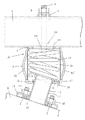
第一実施例の金具基枠1は、図9で示す展開図で表わせる金属板を折り曲げて上下面開口の方形中空体で構成したもので、ある。金属板は、金具基枠1の、前後の構成部片1b,1b´と、左右の構成部片1c,1c´の基端部で取り囲むようにして前記開口部8を備え、該開口部8の隅角部に、開口部8内方向に突出する前記受止部片9を設け、該受止部片9,9間を切欠状にして、前記受止部片9に掛止する、前記接続枠2の掛止部片10を挿通して基枠1内に収める係合孔17を、前記開口部8の両側に連通させて設け、また、左右の構成部片1c,1c´の自由端には前記フランジ1a,1aの構成片(フランジと同一符号で示す)を連設し、該構成片と左右の構成部片1c,1c´の境界部中央に前記止着ボルト5を設けてあり、更に、前後の構成部片1b,1b´の自由端には、金具基枠1上に載せる前記蓋板4の受部片1dを設けてある。
第二実施例の金具基枠1´は、受止部片9を構成する中央部片1´dの両側に前後の構成部片1´b,1´b´又は、左右の構成部片1´c,1´c´を、両側に相対設して構成した、第一、第二の溝状枠体1´A,1´B(図15と図16で示す)を順次接続枠2´に組付けて構成したものである。
2,2´ 接続枠
8 開口部
10 掛止部片
11 コイルばね
p 支柱
S 信号灯器
Claims (2)
- 支柱に設けた腕金に着脱自在に吊設する、中空筒状の金具基枠の下面に、該金具基枠の内外を連通する開口部を形成し、該開口部を通じて前記金具基枠内に配した、信号灯器上に立設する接続枠の上端部に、前記金具基枠に設けた係合孔に掛止する掛止部片を設け、該掛止部片が前記係合孔に係合する方向に押圧するコイルばねを前記金具基枠の内部に納めた、信号灯器の腕金用取付け金具。
- 金具基枠の下面の、開口部の両側に、掛止部片のL字形先端部が係合する長孔を設けた請求項1記載の信号灯器の腕金用取付け金具。
Priority Applications (1)
| Application Number | Priority Date | Filing Date | Title |
|---|---|---|---|
| JP2010045227A JP5438552B2 (ja) | 2010-03-02 | 2010-03-02 | 信号灯器の腕金用取付け金具 |
Applications Claiming Priority (1)
| Application Number | Priority Date | Filing Date | Title |
|---|---|---|---|
| JP2010045227A JP5438552B2 (ja) | 2010-03-02 | 2010-03-02 | 信号灯器の腕金用取付け金具 |
Publications (2)
| Publication Number | Publication Date |
|---|---|
| JP2011180879A JP2011180879A (ja) | 2011-09-15 |
| JP5438552B2 true JP5438552B2 (ja) | 2014-03-12 |
Family
ID=44692310
Family Applications (1)
| Application Number | Title | Priority Date | Filing Date |
|---|---|---|---|
| JP2010045227A Active JP5438552B2 (ja) | 2010-03-02 | 2010-03-02 | 信号灯器の腕金用取付け金具 |
Country Status (1)
| Country | Link |
|---|---|
| JP (1) | JP5438552B2 (ja) |
Cited By (1)
| Publication number | Priority date | Publication date | Assignee | Title |
|---|---|---|---|---|
| CN109285371A (zh) * | 2018-11-13 | 2019-01-29 | 唐文俊 | 一种智能交通信号灯及其使用方法 |
Families Citing this family (4)
| Publication number | Priority date | Publication date | Assignee | Title |
|---|---|---|---|---|
| JP6547202B1 (ja) * | 2018-04-11 | 2019-07-24 | 義烏市源徳進出口有限公司 | 取替便利な交通伝導装置 |
| CN111599195A (zh) * | 2020-05-18 | 2020-08-28 | 安徽省徽腾智能交通科技有限公司 | 一种变换导流方向的智能交通灯的安装装置 |
| CN112669633B (zh) * | 2020-12-29 | 2022-03-11 | 内蒙古高等级公路建设开发有限责任公司 | 一种led节能变光指示灯装置 |
| CN114973722A (zh) * | 2022-07-29 | 2022-08-30 | 山东元捷电子科技有限公司 | 一种移动式道路应急用交通指示信号灯 |
Family Cites Families (3)
| Publication number | Priority date | Publication date | Assignee | Title |
|---|---|---|---|---|
| JPH0681098U (ja) * | 1993-04-19 | 1994-11-15 | 日本信号株式会社 | 信号灯器吊設装置 |
| JP2003331392A (ja) * | 2002-05-16 | 2003-11-21 | Iwabuchi Corp | 信号灯器の腕金用取付金具 |
| JP4705890B2 (ja) * | 2006-07-11 | 2011-06-22 | 信号電材株式会社 | 信号灯器の腕金用取付金具 |
-
2010
- 2010-03-02 JP JP2010045227A patent/JP5438552B2/ja active Active
Cited By (1)
| Publication number | Priority date | Publication date | Assignee | Title |
|---|---|---|---|---|
| CN109285371A (zh) * | 2018-11-13 | 2019-01-29 | 唐文俊 | 一种智能交通信号灯及其使用方法 |
Also Published As
| Publication number | Publication date |
|---|---|
| JP2011180879A (ja) | 2011-09-15 |
Similar Documents
| Publication | Publication Date | Title |
|---|---|---|
| JP5438552B2 (ja) | 信号灯器の腕金用取付け金具 | |
| TW464556B (en) | A joint structure for extruded members | |
| EP1880878B1 (en) | Towing hook mounting member and bumper mechanism with the same | |
| CN103403369B (zh) | 带有螺母的托架 | |
| US6513878B2 (en) | Attachment structure of functional member | |
| US11148717B2 (en) | Fastening element | |
| US7281733B2 (en) | Attachment of airbag module to vehicle | |
| KR102185176B1 (ko) | 고정 구조체 | |
| JP2009029236A (ja) | リヤバンパー取付け構造 | |
| JP5288316B2 (ja) | 吊り金具用補強金具 | |
| JP2016075129A (ja) | 屋根板取り付け金具 | |
| JP2009084982A (ja) | 屋根上取り付け金具 | |
| EP3784551B1 (en) | Device for the temporary interconnection of accessories to a truck or an articulated rig composed of tractor and trailer or semi trailer | |
| JP6737079B2 (ja) | フックの取付構造 | |
| JP5600635B2 (ja) | 歩行者用信号灯器の腕金用取付け金具 | |
| JP2009074305A (ja) | 振れ止め用下地材の固定金具 | |
| JP2001106001A (ja) | 車両用バンパの取付構造及びバンパ取付用グロメット | |
| JP2005042468A (ja) | 溝蓋構造 | |
| JP2013116674A (ja) | ナットプレートの取付構造 | |
| KR20080107038A (ko) | 차량용 스페어타이어 고정장치 | |
| JP5796845B2 (ja) | シートベルトリトラクタの取付構造 | |
| JP2019119240A (ja) | 部品取付け部材 | |
| KR200341952Y1 (ko) | 차량용 접이식 시트의 잠금장치 | |
| JP2007070915A (ja) | 足場板支持用ブラケット | |
| JP4684050B2 (ja) | ロールスクリーン収納ボックス |
Legal Events
| Date | Code | Title | Description |
|---|---|---|---|
| A621 | Written request for application examination |
Free format text: JAPANESE INTERMEDIATE CODE: A621 Effective date: 20120221 |
|
| A977 | Report on retrieval |
Free format text: JAPANESE INTERMEDIATE CODE: A971007 Effective date: 20130612 |
|
| A131 | Notification of reasons for refusal |
Free format text: JAPANESE INTERMEDIATE CODE: A131 Effective date: 20130702 |
|
| A521 | Request for written amendment filed |
Free format text: JAPANESE INTERMEDIATE CODE: A523 Effective date: 20130830 |
|
| TRDD | Decision of grant or rejection written | ||
| A01 | Written decision to grant a patent or to grant a registration (utility model) |
Free format text: JAPANESE INTERMEDIATE CODE: A01 Effective date: 20131126 |
|
| A61 | First payment of annual fees (during grant procedure) |
Free format text: JAPANESE INTERMEDIATE CODE: A61 Effective date: 20131213 |
|
| R150 | Certificate of patent or registration of utility model |
Ref document number: 5438552 Country of ref document: JP Free format text: JAPANESE INTERMEDIATE CODE: R150 Free format text: JAPANESE INTERMEDIATE CODE: R150 |
|
| R250 | Receipt of annual fees |
Free format text: JAPANESE INTERMEDIATE CODE: R250 |
|
| R250 | Receipt of annual fees |
Free format text: JAPANESE INTERMEDIATE CODE: R250 |
|
| R250 | Receipt of annual fees |
Free format text: JAPANESE INTERMEDIATE CODE: R250 |
|
| R250 | Receipt of annual fees |
Free format text: JAPANESE INTERMEDIATE CODE: R250 |
|
| R250 | Receipt of annual fees |
Free format text: JAPANESE INTERMEDIATE CODE: R250 |
|
| R250 | Receipt of annual fees |
Free format text: JAPANESE INTERMEDIATE CODE: R250 |
|
| R250 | Receipt of annual fees |
Free format text: JAPANESE INTERMEDIATE CODE: R250 |
|
| R250 | Receipt of annual fees |
Free format text: JAPANESE INTERMEDIATE CODE: R250 |
|
| R250 | Receipt of annual fees |
Free format text: JAPANESE INTERMEDIATE CODE: R250 |