JP5380767B2 - Head unit assembly method - Google Patents
Head unit assembly method Download PDFInfo
- Publication number
- JP5380767B2 JP5380767B2 JP2006212914A JP2006212914A JP5380767B2 JP 5380767 B2 JP5380767 B2 JP 5380767B2 JP 2006212914 A JP2006212914 A JP 2006212914A JP 2006212914 A JP2006212914 A JP 2006212914A JP 5380767 B2 JP5380767 B2 JP 5380767B2
- Authority
- JP
- Japan
- Prior art keywords
- head
- droplet discharge
- nozzle
- unit
- center
- Prior art date
- Legal status (The legal status is an assumption and is not a legal conclusion. Google has not performed a legal analysis and makes no representation as to the accuracy of the status listed.)
- Active
Links
Images


Landscapes
- Particle Formation And Scattering Control In Inkjet Printers (AREA)
- Coating Apparatus (AREA)
Description
本発明は、部材をプレートの所定の位置に位置決めする位置決め方法に関する。本発明はまた、液滴を吐出するヘッドを有するヘッドユニットを備えた液滴吐出装置、当該ヘッドユニットを組立てるヘッドユニット組立方法、及びヘッドユニット組立装置に関する。 The present invention relates to a positioning method for positioning a member at a predetermined position of a plate. The present invention also relates to a droplet discharge device including a head unit having a head for discharging droplets, a head unit assembly method for assembling the head unit, and a head unit assembly device.
従来から、カラー液晶装置のカラーフィルタ膜や有機エレクトロルミネセンス装置の発光膜などの機能膜を形成する技術として、液体を液滴として吐出する液滴吐出ヘッドを有する液滴吐出装置を用いて、機能膜の材料を含む液状材料の液滴を吐出して基板上の任意の位置に着弾させ、着弾した液状材料を乾燥させて機能膜を形成する技術が知られている。このような膜形成に用いられる液滴吐出装置の液滴吐出ヘッドは、そのノズル列から微小な液滴を精度良く且つ選択的に吐出することができるため、液晶表示装置のカラーフィルタの製造などの他にも、各種の電子デバイスや光デバイス等の製造装置への応用も期待されている。 Conventionally, as a technique for forming a functional film such as a color filter film of a color liquid crystal device or a light emitting film of an organic electroluminescence device, a droplet discharge device having a droplet discharge head for discharging a liquid as a droplet is used. A technique is known in which droplets of a liquid material containing a functional film material are ejected and landed at an arbitrary position on a substrate, and the landed liquid material is dried to form a functional film. Since the droplet discharge head of the droplet discharge device used for forming such a film can accurately and selectively discharge minute droplets from the nozzle row, manufacturing a color filter of a liquid crystal display device, etc. In addition, application to manufacturing apparatuses such as various electronic devices and optical devices is also expected.
このような応用技術を考慮すると、液滴吐出ヘッド自体の性能に加え、液滴吐出ヘッドの液滴吐出ノズルが基板の所望の位置に対向するように液滴吐出ヘッドと基板とを相対移動させる走査機構の位置精度や、その前提となる液滴吐出装置におけるノズル(ノズル列)の位置精度(組付け精度)に、高い精度が要求される。また、吐出対象となる液体等によっては、液滴吐出ヘッドの寿命が短くなり、液滴吐出ヘッドの頻繁な交換も考慮する必要がある。即ち、高い精度が要求される組付けを、頻繁に行うことも考慮する必要がある。特許文献1には、複数の液滴吐出ヘッドを、単一のキャリッジに安定に且つ精度良く組み付けることができるヘッドユニットの構成および組立方法(複数IJヘッド搭載サブキャリッジおよびその組立方法)が開示されている。
Considering such applied technology, in addition to the performance of the droplet discharge head itself, the droplet discharge head and the substrate are relatively moved so that the droplet discharge nozzle of the droplet discharge head faces a desired position of the substrate. High accuracy is required for the positional accuracy of the scanning mechanism and the positional accuracy (assembly accuracy) of the nozzles (nozzle rows) in the droplet discharge device which is the premise thereof. In addition, depending on the liquid to be ejected, the life of the droplet ejection head is shortened, and frequent replacement of the droplet ejection head needs to be considered. In other words, it is necessary to consider frequently performing assembly requiring high accuracy.
しかしながら、一般的に、液滴吐出ヘッド単体には形状誤差が存在するため、ヘッドユニット組立時に液滴吐出ヘッドの位置を代表する部位として基準点に対して位置決めされる標準点に対して、液滴吐出ノズルの位置誤差が存在する。液滴吐出ノズルの位置誤差が増大すると、組立てられたヘッドユニットにおける液滴吐出ノズルの位置精度が低下するという課題があった。 However, in general, since there is a shape error in a single droplet discharge head, the liquid point is not compared with a standard point that is positioned with respect to a reference point as a portion representing the position of the droplet discharge head when the head unit is assembled. There is a position error of the droplet discharge nozzle. When the position error of the droplet discharge nozzle increases, there is a problem that the position accuracy of the droplet discharge nozzle in the assembled head unit is lowered.
本発明は、上記課題を解決するためのものであり、液滴吐出ヘッドの基準点に対する液滴吐出ノズルの位置誤差を抑制して、組み付けられた液滴吐出ヘッドにおける液滴吐出ノズルの位置誤差を小さくすることで、ヘッドユニットにおける液滴吐出ノズルの位置精度を高くすることができる位置決め方法、ヘッドユニット組立方法、ヘッドユニット組立装置、ヘッドユニット、及び液滴吐出装置を実現することを目的とする。 The present invention is for solving the above-described problem, and suppresses the position error of the droplet discharge nozzle with respect to the reference point of the droplet discharge head, thereby reducing the position error of the droplet discharge nozzle in the assembled droplet discharge head. It is an object to realize a positioning method, a head unit assembly method, a head unit assembly device, a head unit, and a droplet discharge device that can increase the positional accuracy of a droplet discharge nozzle in the head unit To do.
本発明によるヘッドユニット組立方法は、液滴吐出ヘッドがユニットプレートに固定されたヘッドユニットを形成するヘッドユニット組立方法であって、液滴吐出ヘッドが有する複数の液滴吐出ノズルから傾きを算出し、傾きが規格を満たすか否かを判定する工程と、傾きの傾き量が規格を満たさない場合に、傾きを補正する傾き補正工程と、複数の液滴吐出ノズルにより算出される重心点の位置データと、予め取得してある基準位置データを比較し、ずれ量が規格を満たすか否か判定する工程と、ずれ量が規格を満たさない場合に、位置補正を行い液滴吐出ヘッドを基準位置に位置決めする位置決め工程を有することを特徴とする。
A head unit assembly method according to the present invention is a head unit assembly method for forming a head unit in which a droplet discharge head is fixed to a unit plate, and calculates an inclination from a plurality of droplet discharge nozzles of the droplet discharge head. , A step of determining whether or not the inclination satisfies the standard, an inclination correction step of correcting the inclination when the inclination amount of the inclination does not satisfy the standard, and a position of the center of gravity calculated by a plurality of droplet discharge nozzles The process of comparing the data with the reference position data acquired in advance to determine whether or not the deviation amount satisfies the standard, and when the deviation amount does not meet the standard, the position is corrected and the droplet discharge head is moved to the reference position. It has the positioning process which positions to.
本発明において、ヘッドユニット組立方法は、複数の液滴吐出ノズルが整列してノズル列を形成していることが好ましい。
In the present invention, in the head unit assembling method, it is preferable that a plurality of droplet discharge nozzles are aligned to form a nozzle row.
このヘッドユニット組立方法によれば、液滴吐出ヘッドが有する一本のノズル列に含まれる液滴吐出ノズルのうちの2以上の液滴吐出ノズルの重心点が所定の位置に位置決めされることで、当該液滴吐出ヘッドがユニットプレートの所定の位置に位置決めされている。これにより、当該一本のノズル列に含まれる液滴吐出ノズルの位置決め精度を高くすることができる。
According to this head unit assembly method, the center of gravity of two or more droplet discharge nozzles among the droplet discharge nozzles included in one nozzle row of the droplet discharge head is positioned at a predetermined position. The droplet discharge head is positioned at a predetermined position on the unit plate. Thereby, the positioning accuracy of the droplet discharge nozzles included in the one nozzle row can be increased.
本発明において、ヘッドユニット組立方法は、複数の液滴吐出ノズルは第一の基準ノズルと第二の基準ノズルとであって、第一の基準ノズルの中心点と第二の基準ノズルの中心点とを結ぶ直線が複数の液滴吐出ノズルと描画対象とを相対的に移動させる複数の移動方向の中の第一の方向に対して一定の角度をなして、複数の液滴吐出ヘッドがユニットプレートに取り付けられており、複数の液滴吐出ヘッドは、ユニットプレートに位置決めされた状態で、第一の基準ノズルの中心点から第二の基準ノズルの中心点に向かう方向が第一の方向である第一の液滴吐出ヘッドと、第一の基準ノズルの中心点から第二の基準ノズルの中心点に向かう方向が、第一の方向とは異なる第二の方向である第二の液滴吐出ヘッドと、を含むことが好ましい。
In the present invention, in the head unit assembling method, the plurality of droplet discharge nozzles are the first reference nozzle and the second reference nozzle, and the center point of the first reference nozzle and the center point of the second reference nozzle A plurality of droplet discharge heads are united by a straight line connecting a plurality of droplet discharge nozzles and a first direction among a plurality of movement directions for relatively moving a plurality of droplet discharge nozzles and a drawing target. The plurality of droplet discharge heads, which are attached to the plate, are positioned on the unit plate, and the direction from the center point of the first reference nozzle to the center point of the second reference nozzle is the first direction. A first droplet discharge head and a second droplet in which the direction from the center point of the first reference nozzle to the center point of the second reference nozzle is a second direction different from the first direction And a discharge head.
このヘッドユニット組立方法によれば、液滴吐出装置上の液滴吐出ヘッドの配置姿勢に拠らず、液滴吐出ヘッドは、ユニットプレートに取り付けられる際に、2以上の液滴吐出ノズルの重心点が所定の位置に位置決めされることで、当該液滴吐出ヘッドがユニットプレートの所定の位置に位置決めさている。これにより、液滴吐出装置上の液滴吐出ヘッドの配置姿勢に拠らず、液滴吐出装置の液滴吐出ヘッドの組立位置精度を高くすることができる。 According to this head unit assembly method, the center of gravity of the two or more droplet discharge nozzles can be used when the droplet discharge head is attached to the unit plate regardless of the arrangement posture of the droplet discharge head on the droplet discharge device. When the point is positioned at a predetermined position, the droplet discharge head is positioned at a predetermined position of the unit plate. Thereby, it is possible to increase the assembly position accuracy of the droplet discharge head of the droplet discharge device regardless of the arrangement posture of the droplet discharge head on the droplet discharge device.
以下、本発明に係る位置決め方法、ヘッドユニット組立方法、ヘッドユニット組立装置、ヘッドユニット、及び液滴吐出装置の一実施形態について図面を参照して、説明する。 DESCRIPTION OF EXEMPLARY EMBODIMENTS An embodiment of a positioning method, a head unit assembling method, a head unit assembling apparatus, a head unit, and a droplet discharge apparatus according to the invention will be described below with reference to the drawings.
(液滴吐出装置)
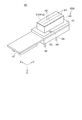
最初に、液滴吐出装置の全体構成について、図1を参照して説明する。図1は液滴吐出装置の概略構成を示す外観斜視図である。図1に示すように、液滴吐出装置1は、液状体を液滴として吐出して着弾させる対象である描画対象としての基板Wを載置するための基板ステージ14と、基板ステージ14を主走査方向に移動させるX軸走査機構10と、を備えている。また、複数の液滴吐出ヘッド40(図2参照)を搭載するヘッドユニット30(図5参照)を有するキャリッジ22(図5参照)を備えるキャリッジユニット20と、キャリッジユニット20を副走査方向に移動させるY軸走査機構17と、を備えている。図1に矢印で示したように、主走査方向をX軸方向、主走査方向(X軸方向)に略直交する副走査方向をY軸方向、X軸方向及びY軸方向に直交する方向をZ軸方向、Z軸方向回りの回動方向をθ方向と表記する。
(Droplet discharge device)
First, the overall configuration of the droplet discharge device will be described with reference to FIG. FIG. 1 is an external perspective view showing a schematic configuration of a droplet discharge device. As shown in FIG. 1, a
基板ステージ14は、基板Wを真空吸着して固定する吸着テーブルであり、ステージ回動機構16を介してX軸移動プレート12に、θ方向に回動可能に固定されている。X軸走査機構10は、X軸移動プレート12と、床上に設置されてX軸方向に延在しており、X軸移動プレート12をエアスライダ(図示省略)を介してX軸方向に移動させるリニアモータ11aを備えた一対のX軸ガイドレール11,11とを有している。一対のX軸ガイドレール11,11を挟むように、収容ボックス9が2個所配設されている。収容ボックス9内には、エアスライダに圧縮空気を供給するエアー供給手段の給気パイプや、X軸走査機構10に駆動信号などを送る信号ケーブルなどが収容されている。
The
キャリッジユニット20は、キャリッジプレート21を備え、キャリッジ22がキャリッジプレート21にθ方向に回動可能に取り付けられている。キャリッジプレート21は、一対のY軸ガイドレール18,18に差し渡されるようにして配置されている。差し渡されたキャリッジプレート21の上には、各液状体が貯留されたタンクから配管を経由して送り込まれた液状体を所定量貯留して、各液滴吐出ヘッド40に液状体を供給する液状体供給ユニット23と、各液滴吐出ヘッド40を駆動するための電気信号を供給するヘッド用電装ユニット24とが、載置されている。
The
Y軸走査機構17は、10基のキャリッジユニット20をエアスライダ(図示省略)を介してY軸方向に移動させるリニアモータ18aを備えた一対のY軸ガイドレール18,18を有している。10基のキャリッジユニット20はそれぞれ個別にY軸方向に移動可能である。一対のY軸ガイドレール18,18は、床上に間隔を置いて立脚した6本の支持スタンド19上に、X軸走査機構10を跨ぐように配設されている。
The Y-
一対のY軸ガイドレール18,18の間には、キャリッジ22(ヘッドユニット30)に搭載された複数の液滴吐出ヘッド40のノズルの目詰まりの解消や、ノズル面の異物や汚れの除去、などのメンテナンスを行うメンテナンスユニット26が、複数の液滴吐出ヘッド40を臨む位置に配設されている。
Between the pair of Y-
(液滴吐出ヘッド)
次に、図2を参照して液滴吐出ヘッド40について説明する。図2は、液滴吐出ヘッドをノズル形成プレート側から見た外観斜視図である。この液滴吐出ヘッド40は、いわゆる2連のものであり、2連の接続針46,46を有する液体導入部45と、液体導入部45の側方に連なる2連のヘッド基板47と、液体導入部45に連なる2連のポンプ部48と、ポンプ部48に連なるノズル形成プレート41とを備えている。液体導入部45には、配管接続部材が接続され、ヘッド基板47には、フレキシブルフラットケーブルが接続される。一方、このポンプ部48とノズル形成プレート41とにより、方形のヘッド本体40Aが構成されている。
(Droplet ejection head)
Next, the
ポンプ部48の基部側、すなわちヘッド本体40Aの基部側は、液体導入部45を受けるべく方形フランジ状にフランジ部44が形成されている。このフランジ部44には、液滴吐出ヘッド40を副ヘッド保持部材33(図3参照)に固定する小ねじ用のねじ孔(雌ねじ)49が一対形成されている。この一対のねじ孔49,49は、両長辺部分に位置し、且つノズル形成面41aの中心に対し点対称となるように配設されている。詳細は後述するが、副ヘッド保持部材33を貫通してねじ孔49に螺合したヘッド止めねじ37により、液滴吐出ヘッド40が副ヘッド保持部材33に固定される(図3参照)。
A
ノズル形成プレート41のノズル形成面41aには、ノズル形成プレート41に形成されており液滴を吐出する吐出ノズル42から成る2本のノズル列43,43が形成されている。2本のノズル列43,43は相互に平行に列設されており、各ノズル列43は、等ピッチで並べた吐出ノズル42を180個(図示では模式的に表している)有している。すなわち、ヘッド本体40Aのノズル形成面41aには、その中心線を挟んで2本のノズル列43,43が対称に配設されている。
On the
(液滴吐出ヘッドの取付)
次に、液滴吐出ヘッド40のユニットプレート51への取付構造について、図3を参照して説明する。図3は、液滴吐出ヘッドのユニットプレートへの取付構造を示す図である。図3(a)は、ユニットプレートに取り付けられた液滴吐出ヘッドをノズルプレート側からみた平面図であり、図3(b)は、図3(a)にA−Aで示した断面の断面図である。
(Installation of droplet discharge head)
Next, a structure for attaching the
図3(a)及び(b)に示すように、ユニットプレート51にはヘッド開口51aが形成されており、主ヘッド保持部材32がヘッド開口51aを略覆うように、ユニットプレート51に固定されている。主ヘッド保持部材32は、主ヘッド保持部材32に形成された孔を貫通してユニットプレート51に形成されたねじ孔に螺合した3本の保持部材ねじ38,38,38により、ユニットプレート51に固定されている。(以降、主ヘッド保持部材32がセットされた側を「裏面側」と表記し、反対側を「表面側」と表記する。)
As shown in FIGS. 3A and 3B, a
主ヘッド保持部材32にはフランジ開口32aが形成されており、副ヘッド保持部材33は、その長辺方向の両端部でフランジ開口32aを跨ぐようにして、主ヘッド保持部材32の裏面側に固定されている。副ヘッド保持部材33は、副ヘッド保持部材33に形成された孔を貫通して主ヘッド保持部材32に形成されたねじ孔に螺合した2本の保持部材ねじ38,38により、主ヘッド保持部材32に固定されている。
A
副ヘッド保持部材33は、ステンレス等で構成された略長方形の平板状に形成されている。副ヘッド保持部材33には、その中央に液滴吐出ヘッド40のヘッド本体40Aが挿通する方形のヘッド本体開口33dが形成されている。上記したように、副ヘッド保持部材33は、フランジ開口32aを跨ぐようにして主ヘッド保持部材32の裏面側にセットされている。これに対し液滴吐出ヘッド40は、そのヘッド本体40Aをヘッド本体開口33dに挿通してヘッド本体40Aを副ヘッド保持部材33の裏面側に突出させるようにして、主ヘッド保持部材32の表面側からセットされている。液滴吐出ヘッド40は、副ヘッド保持部材33に形成された孔を貫通してフランジ部44に形成された一対のねじ孔49,49に螺合した2本のヘッド止めねじ37,37により、副ヘッド保持部材33に固定されている。
The sub
副ヘッド保持部材33のヘッド本体開口33dの周囲には、上記した一対のねじ孔49,49に対応する2つの貫通孔、及びヘッド本体開口33dの中心線上において第一調整穴33aと第二調整穴33bとが形成されている。第一調整穴33a及び第二調整穴33bは、後述するヘッドユニット組立装置100(図7参照)における位置補正用の調整ピン121(図7参照)が係合される部位である。この場合、一対の調整ピン121,121の係合が無理なく為されるように、第一調整穴33aが円形に、第二調整穴33bが上記中心線方向に長い長円形に形成されている。
Around the head body opening 33d of the sub
また、ヘッド本体開口33dの中心線上において、第一調整穴33a及び第二調整穴33bのヘッド本体開口33dの反対側には2つの接着剤孔33c,33cが、ヘッド本体開口33dに関して略対称位置に形成されている。接着剤孔33cは副ヘッド保持部材33の横断方向に延びる長孔となっている。接着剤孔33cに接着剤を注入して、当該接着剤(図示省略)によって副ヘッド保持部材33を主ヘッド保持部材32に接着固定する。
On the center line of the head main body opening 33d, two
なお、液滴吐出ヘッド40がヘッド止めねじ37により副ヘッド保持部材33に固定されており、副ヘッド保持部材33の保持部材ねじ38および接着剤による主ヘッド保持部材32への固定がなされていない状態では、液滴吐出ヘッド40は、ユニットプレート51に対して、フランジ部44とフランジ開口32aとの隙間分、またはヘッド基板47とヘッド開口51aとの隙間分だけ移動可能に、固定された状態となる。本実施形態では、このような状態を「仮装着」状態と表記する。副ヘッド保持部材33及びヘッド基板47はフランジ開口32aの開口より大きいため、仮装着状態の液滴吐出ヘッド40(液滴吐出ヘッド40が主ヘッド保持部材32を挟んで副ヘッド保持部材33に固定された液滴吐出ヘッド40と副ヘッド保持部材33との組)が主ヘッド保持部材32から脱落することはない。液滴吐出ヘッド40のユニットプレート51への組付けは、液滴吐出ヘッド40を仮装着し、次に仮装着状態の液滴吐出ヘッド40の位置調整を行った後に、副ヘッド保持部材33の主ヘッド保持部材32への接着剤による接着固定、及び保持部材ねじ38によるねじ固定を行うことで実行される。
The
(基準ピン)
次に、液滴吐出ヘッド40のユニットプレート51上の位置を規定する際の基準となる基準ピン54について、図4を参照して説明する。一対の基準ピン54,54(図5参照)は、ヘッドユニット30が取り付けられたキャリッジユニット20を液滴吐出装置1に取り付ける際にθ方向に位置決め(位置認識)するための基準としても用いられる。また、ヘッドユニット30(ユニットプレート51)をヘッドユニット組立装置100(図7参照)に取り付ける際にθ方向に位置決めするための基準としても用いられる。一対の基準ピン54,54のユニットプレート51上の配置位置については後述する。
(Reference pin)
Next, the
図4(a)は、基準ピンを基準マーク孔側から見た平面図であり、図4(b)は、基準ピンの側面図である。図4に示すように、各基準ピン54は、円柱状のピン本体と、ピン本体の先端面57の中央部に形成した凹状、具体的には孔状の基準マーク孔56とで構成されている。ピン本体は、ユニットプレート51に圧入するための基部圧入部54bと、基部圧入部54bに連なる胴部54aと、胴部54aの先端に突出形成したマーク形成部54cとから成り、このマーク形成部54cの先端面57に基準マーク孔56が形成されている。
4A is a plan view of the reference pin viewed from the reference mark hole side, and FIG. 4B is a side view of the reference pin. As shown in FIG. 4, each
先端面57は鏡面加工されており、この先端面57の中心位置に基準マーク孔56となる小孔が穿孔されている。小孔(基準マーク孔56)は、例えば直径0.3mm程度のものであり、基部圧入部54bから胴部54aにかけてその軸心部分に形成した軸心孔に連通している。なお、基準ピン54は、断面を円形状として説明したが、楕円状でも、多角形状でも構わない。さらに、小孔の基準マーク孔56も、小孔に限定されるものではなく、充分なコントラストが得られるような溝を持つ凹形状であればよく、その凹の平面形状も円形に限定されるものではない。
The
このように形成された基準ピン54は、ユニットプレート51に形成した取付用の孔部分に基部圧入部54bを打ち込むようにして圧入される。ユニットプレート51に圧入された基準ピン54は、先端面57の高さが、ユニットプレート51に取り付けられた液滴吐出ヘッド40のノズル形成面41a(図2又は図3参照)と略同一高さとなるように、ユニットプレート51の裏面側から突出している。すなわち、基準ピン54の画像認識面となる先端面57と、液滴吐出ヘッド40の画像認識面となるノズル形成面41aとが、略同一平面内に位置するようになっている。
The
(ヘッドユニット)
次に、図5を参照してヘッドユニット30の全体構成について説明する。図5は、キャリッジにおけるヘッドユニットの平面図である。図3を参照して説明したように、ヘッドユニット30のユニットプレート51には、主ヘッド保持部材32及び副ヘッド保持部材33を介して液滴吐出ヘッド40が取り付けられている。図5に示すように、1基のヘッドユニット30は、12個の液滴吐出ヘッド40を備えている。ユニットプレート51には、基準マーク孔56(図4参照)が形成された一対の基準ピン54,54が固定されており、12個の液滴吐出ヘッド40はそれぞれ基準ピン54に形成された基準マーク孔56を基準として、適切な位置に位置決めして固定されている。基準マーク孔56が、液滴吐出ヘッドを位置決めする際に基準とする基準点に相当する。
(Head unit)
Next, the overall configuration of the
ユニットプレート51には、また、第一位置規制孔52aと、第二位置規制孔52bと、が形成されている。第一位置規制孔52a及び第二位置規制孔52bは、キャリッジ枠62に立設された位置規制ピン63に嵌合することで、ユニットプレート51(ヘッドユニット30)のキャリッジ枠62に対するX軸とY軸とに平行な平面方向の位置を規定している。この場合、一対の位置規制ピン63,63の相互間の距離がばらついても係合が無理なく為されるように、第一位置規制孔52aが円形に、第二位置規制孔52bが第一位置規制孔52aの中心と第二位置規制孔52bの中心とを結ぶ直線の方向に長い長円形に形成されている。図5に示したX軸、Y軸、Z軸は、図1に示したX軸、Y軸、Z軸と同一である。即ち、ヘッドユニット30が液滴吐出装置1に取り付けられた状態では、液滴吐出ヘッド40に形成されたノズル列43(図2参照)は、Y軸方向に延在する構成になっている。ヘッドユニット30は、ユニットプレート51に形成されたユニット固定孔53を貫通してキャリッジ枠62に形成されたねじ孔64に螺合した4本のユニット固定ねじ68により、キャリッジ枠62に固定されている。
The
次に、液滴吐出ヘッド40と、一対の基準マーク孔56,56と、第一位置規制孔52aと、第二位置規制孔52bとの、ユニットプレート51上の位置関係について説明する。図5に一点鎖線で示した線Aは、一対の基準マーク孔56,56のそれぞれの中心を通る仮想線である。同じく一点鎖線で示した線Bは、一対の基準マーク孔56,56の中点Gで線Aと直交する仮想線である。ヘッドユニット30が液滴吐出装置1に取り付けられた状態では、線Aは主操作方向であるX軸方向に延在し、線Bは副操作方向であるY軸方向に延在する。第一位置規制孔52aと、第二位置規制孔52bとも、その中心を線Aが通る位置に形成されている。図5に示したように、12個の液滴吐出ヘッド40をそれぞれヘッド400a,400b,400c,400d,400e,400f,401a,401b,401c,401d,401e,401fと表記する。
Next, the positional relationship on the
ヘッド400aとヘッド400dとはY軸方向にノズル列43の長さだけずれている。ヘッド400aのノズル列43,43とヘッド400dのノズル列43,43とで、液滴吐出ヘッド40のノズル列43の2倍の長さのノズル列を構成している。なお、ノズル列43を構成する吐出ノズル42の一部を使用しない場合には、ヘッド400aとヘッド400dとの使用する吐出ノズル42が連続したノズル列となるように構成する。同様に、ヘッド400bとヘッド400eとで、又はヘッド400cとヘッド400fとで、ノズル列43の2倍の長さのノズル列を構成している。ヘッド400aとヘッド400bとヘッド400cとはY軸方向にノズル列43の長さの3分の1の長さだけずれている。従って、6個のヘッド400a,400b,400c,400d,400e,400fは、Y軸方向にノズル列43の長さの3分の1の長さだけずれて配列されている。6個のヘッド400a,400b,400c,400d,400e,400fは、X軸方向に等間隔で、線Bの両側に各3個づつ配置されている。
The
ヘッド401f,401e,401d,401c,401b,401aは、ヘッド400a,400b,400c,400d,400e,400fに対して中点Gに関して点対称の位置及び方向に配置されている。ヘッド401f,401e,401d,401c,401b,401aのそれぞれを固定するための主ヘッド保持部材32及び副ヘッド保持部材33も、ヘッド400a,400b,400c,400d,400e,400fのそれぞれを固定するための主ヘッド保持部材32及び副ヘッド保持部材33に対して中点Gに関して点対称の位置及び方向に配置されている。また、ユニットプレート51の外形形状も中点Gに関して点対称となる形状であり、第一位置規制孔52aと、第二位置規制孔52bとは、線Bに関して互いに対称の位置に形成されており、4個所のねじ孔64も線Bに関して互いに対称の位置に形成されている。
The
(吐出ノズル位置測定)
次に、図6を参照して、液滴吐出ヘッド40における吐出ノズル42の位置測定について説明する。図6は、吐出ノズルが形成された液滴吐出ヘッドのノズル形成面の模式平面図である。
(Discharge nozzle position measurement)
Next, the position measurement of the
液滴吐出ヘッド40は、180個の吐出ノズル42からなるノズル列43を2本有している。それぞれのノズル列43を、Aノズル列43A、Bノズル列43Bと表記する。Aノズル列43Aの一番端の吐出ノズル42を1番ノズル001Aと表記し、並び順に二番目の吐出ノズル42を2番ノズル002Aと表記し、180番目の吐出ノズル42を180番ノズル180Aと表記する。Bノズル列43Bの吐出ノズル42も同様に、1番ノズル001Bから180番ノズル180Bと表記する。液滴吐出ヘッド40が図5に示したヘッド400aからヘッド400fのようにユニットプレート51に取り付けられる場合は、図6に示したX2軸方向とY2方向とが、図5に示したX軸方向とY方向とに一致する。液滴吐出ヘッド40が図5に示したヘッド401aからヘッド401fのようにユニットプレート51に取り付けられる場合は、図6に示したX1軸方向とY1方向とが、図5に示したX軸方向とY方向とに一致する。
The
吐出ノズル42の位置は、Aノズル列43Aの1番ノズル001Aと180番ノズル180Aとの重心点(中点)を基準にして測定する。最初に、基準線として、1番ノズル001Aと180番ノズル180Aとを検出して、1番ノズル001Aの中心と180番ノズル180Aの中心とを通る仮想のAノズル列線430Aを規定する。Aノズル列線430Aの延在方向をY軸(図6では、Y1軸又はY2軸)方向と規定する。また、基準点として、1番ノズル001Aの中心と180番ノズル180Aの中心との中点であるA列重心420Aを規定する。Aノズル列43Aを構成する吐出ノズル42の位置は、それぞれの中心の、A列重心420AからのAノズル列線430Aの延在方向(Y軸方向)の距離と、Aノズル列線430Aからの距離(ずれ量)とで表す。
The position of the
Bノズル列43Bを構成する吐出ノズル42の位置測定の基準とするBノズル列線430Bは、Aノズル列線430Aに対して、Aノズル列43AとBノズル列43Bとの距離の規格値だけ離れた、Aノズル列線430Aに平行な仮想線を規定する。Bノズル列43Bを構成する吐出ノズル42の位置は、それぞれの中心の、A列重心420AからのAノズル列線430Aの延在方向(Y軸方向)の距離と、Bノズル列線430Bからの距離(ずれ量)とで表す。それぞれの吐出ノズル42の位置が規定された位置どおりであれば、Bノズル列線430Bは、Bノズル列43Bを構成する各吐出ノズル42の中心を通る直線となる。
The B
なお、図6に示したB列重心420Bは、1番ノズル001Bの中心と180番ノズル180Bの中心との中点であり、ノズル重心420Gは、1番ノズル001Aの中心と180番ノズル180Aの中心と1番ノズル001Bの中心と180番ノズル180Bの中心との重心点である。図6に示したそれぞれの吐出ノズル42の位置は、規定された位置どおりの位置であって、A列重心420Aは、Aノズル列43Aを構成する全部の吐出ノズル42の重心点でもあり、B列重心420Bは、Bノズル列43Bを構成する全部の吐出ノズル42の重心点でもある。同様に、ノズル重心420Gは、Aノズル列43A及びBノズル列43Bを構成する全部の吐出ノズル42、即ち液滴吐出ヘッド40が有する全ての吐出ノズル42の重心点でもある。Aノズル列43A又はBノズル列43Bが、第一のノズル列又は第二のノズル列に相当する。A列重心420A又はB列重心420Bが、複数の液滴吐出ノズルのうちの2以上の液滴吐出ノズルの重心点又は第一のノズル列を構成する2以上の液滴吐出ノズルの重心点に相当し、ノズル重心420Gが、複数の液滴吐出ノズルのうちの2以上の液滴吐出ノズルの重心点又は液滴吐出ノズルが形成する四角形の重心点に相当する。
6 is the midpoint between the center of the
基準であるAノズル列線430Aを規定する二点である1番ノズル001A及び180番ノズル180AのAノズル列線430Aからの距離(ずれ量)は、0である。Y軸方向の基準であるA列重心420Aを規定する二点である1番ノズル001A及び180番ノズル180AのA列重心420AからのY軸方向の距離の規定値からの誤差(ずれ量)は、1番ノズル001Aと180番ノズル180Aとのノズル間寸法の規定値からの誤差の二分の一になる。Aノズル列43Aを構成する各吐出ノズル42の中心からAノズル列線430Aまでの距離は、0が望ましく、Aノズル列の規格値以下であることが必要である。Bノズル列43Bを構成する各吐出ノズル42の中心からBノズル列線430Bまでの距離は、0が望ましく、Aノズル列の規格値より大きいBノズル列の規格値以下であることと、距離のばらつきがAノズル列の規格値の2倍位以内であることと、が必要である。
The distance (shift amount) from the A
(ヘッドユニット組立装置)
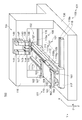
次に、ヘッドユニット30を組立てるヘッドユニット組立装置100について説明する。ヘッドユニット組立装置100は、上記したヘッドユニット30を組立対象物とし、ユニットプレート51に仮装着した12個の液滴吐出ヘッド40をそれぞれ精度良く位置決めして接着(一次固定)するものである。なお、このヘッドユニット組立装置100で、液滴吐出ヘッド40を一次固定したヘッドユニット30は、保持部材ねじ38を用いてさらに固定する二次固定工程及び洗浄工程を経て、キャリッジ枠62にセットされる。図7は、ヘッドユニット組立装置の構成を示す模式図である。
(Head unit assembly equipment)
Next, the head
図7に示すように、ヘッドユニット組立装置100は、ユニット移動装置101、ヘッド補正装置102、接着固定装置(図示省略)、及び認識装置104を備えている。ユニット移動装置101は、ヘッドユニット30を搭載し、これをX軸及びY軸に平行な平面内においてX軸方向、Y軸方向、θ方向に移動させる。ヘッド補正装置102は、ユニットプレート51に仮装着されている各液滴吐出ヘッド40の位置を適切な位置に合わせ込む位置補正を行う。ヘッド補正装置102が、位置調整部に相当する。接着固定装置は、接着剤孔33c(図3参照)に流入させるように接着剤を供給して、ユニットプレート51に対して位置補正された各液滴吐出ヘッド40を、当該位置に一次固定(接着固定)する。認識装置104は、液滴吐出ヘッド40の位置補正に先立ってユニットプレート51及び各液滴吐出ヘッド40を位置認識する。ヘッドユニット組立装置100はまた、これらユニット移動装置101、ヘッド補正装置102、接着固定装置、及び認識装置104を統括制御する制御装置(図示省略)を備えている。制御装置は、算出部に相当する演算装置を含んでいる。制御装置と認識装置104とが、設定位置取得部に相当する。ユニット移動装置101、ヘッド補正装置102、接着固定装置、及び認識装置104は、機台106の上、または機台106の上に設置された支持スタンド116に支持されるように設置されている。
As shown in FIG. 7, the head
ユニット移動装置101は、組立対象物であるヘッドユニット30を載置して保持する保持テーブル110を備えている。また、保持テーブル110が固定されており、保持テーブル110をθ方向に回動することで保持テーブル110に載置されたヘッドユニット30をθ方向に回動する回動機構109を備えている。ユニット移動装置101は、また、回動機構109をX軸方向に移動することでヘッドユニット30をX軸方向に移動するX軸移動機構107と、回動機構109をY軸方向に移動することでヘッドユニット30をY軸方向に移動するY軸移動機構108とを備えている。
The
Y軸移動機構108は、Y軸移動プレート117と、機台106の上にY軸方向に延在するように設けられており、Y軸移動プレート117をエアスライダ(図示省略)を介してY軸方向に移動させるリニアモータ118aを備えた一対のY軸レール118,118とを有している。X軸移動機構107は、X軸移動プレート112と、Y軸移動プレート117の上にX軸方向に延在するように設けられており、X軸移動プレート112をエアスライダ(図示省略)を介してX軸方向に移動させるリニアモータ111aを備えた一対のX軸レール111,111とを有している。回動機構109は、X軸移動プレート112に固定された固定プレート119aと、図示省略した回動モータを介して固定プレート119aにθ方向に回動可能に支持されている回動プレート119bとを有している。保持テーブル110は、回動プレート119bに固定されている。
The Y-
保持テーブル110には、保持テーブル110に固定されるユニットプレート51が当接する部分である略長方形のユニット受部162が2個所形成されている。2個所のユニット受部162は、X軸及びY軸に略平行な平面であって、Z軸方向の位置が略同一の平面である。ユニット受部162の中央付近には位置規制ピン163が立設されている。1個所のユニット受部162にはそれぞれ2個所のねじ孔164が形成されている。ユニット受部162の両側には、マスク受部161が形成されている。マスク受部161は、ユニット受部162より高くなっている。マスク受部161は、後述するアライメントマスク200(図9参照)を取り付ける際に、アライメントマスク200を載置するために使用される。図示省略したが、マスク受部161には、アライメントマスク200を位置決めするための位置決め構造が設けられている。
The holding table 110 is formed with two substantially rectangular
認識装置104は、ヘッドなどの画像を認識するためのカメラ143及びレンズ144と、対象物を照明するための照明装置146と、カメラ143及びレンズ144をZ軸方向に移動してピント調節を行うためのカメラ昇降機構147及びカメラ昇降モータ148と、を有している。認識装置104は、カメラ143、レンズ144、照明装置146、カメラ昇降機構147、及びカメラ昇降モータ148の組を、一対備えている。認識装置104は、レンズ144が保持テーブル110上に載置されたヘッドユニット30に対向できるように、支持スタンド116に支持されている。
The recognizing
ヘッド補正装置102は、一対の調整ピン121,121を有している。一対の調整ピン121,121は、副ヘッド保持部材33に形成された第一調整穴33aと第二調整穴33bとに係合して、ユニットプレート51に仮装着された液滴吐出ヘッド40を適切な位置に位置決めするために微少移動させる力を副ヘッド保持部材33に印加する。ヘッド補正装置102は、また、図7では認識装置104の影になる部分に設けられたピンX軸移動機構、ピンY軸移動機構、ピン回動機構、および調整ピン昇降機構、を有している。調整ピン昇降機構によって調整ピン121を下降させることで第一調整穴33aまたは第二調整穴33bに係合させる。ピンX軸移動機構とピンY軸移動機構とによって、X軸およびY軸に平行な方向に第一調整穴33a及び第二調整穴33bに係合した一対の調整ピン121,121を移動させること、及び、ピン回動機構によってθ方向に回動させることで、ユニットプレート51に仮装着された液滴吐出ヘッド40を微少移動させて、適切な位置に位置決めする。一対の調整ピン121,121相互のX軸Y軸平面方向の位置関係は固定であって、ピンX軸移動機構、ピンY軸移動機構、およびピン回動機構によって同時に移動させられる。調整ピン昇降機構による移動は、調整ピン121毎に個別に行われる。
The
次に、図8を参照して、ヘッドユニット30が保持テーブル110に載置された状態について説明する。図8は、保持テーブルと保持テーブルに載置されたヘッドユニットの平面図である。上述したように、ヘッドユニット30のユニットプレート51には、第一位置規制孔52a及び第二位置規制孔52bと、ユニット固定孔53とが形成されている。保持テーブル110には、2個所のユニット受部162と、2個所の位置規制ピン163と、4個所のねじ孔164と、が形成されている。図8に示すように、ヘッドユニット30は、保持テーブル110に設けられた位置規制ピン163をユニットプレート51に形成された第一位置規制孔52a及び第二位置規制孔52bに嵌入させることで、保持テーブル110に対して位置決めされている。位置決めされたヘッドユニット30は、ユニットプレート51に形成されたユニット固定孔53を貫通して保持テーブル110に形成されたねじ孔164(図7参照)に螺合した4本のユニット固定ねじ68により、保持テーブル110に固定されている。回動機構109と保持テーブル110とのX軸,Y軸に平行な平面方向の位置は、回動機構109の回動中心109Gが、保持テーブル110の略中央に位置するように構成されている。一対の基準マーク孔56,56は、回動中心109Gを通り、X軸方向に延在する直線上であって、回動中心109Gを挟んで対称な位置にその中心が位置する。図5を参照して説明したように、ヘッドユニット30が液滴吐出装置1に取り付けられた状態では、液滴吐出ヘッド40に形成されたノズル列43は、Y軸方向に延在する構成になっている。ヘッドユニット組立装置100による位置調整が完了した液滴吐出ヘッド40に形成されたノズル列43は、Y軸方向に延在する。
Next, a state where the
(アライメントマスク)
次に、アライメントマスク200について、図9を参照して詳細に説明する。図9は、アライメントマスクの概略構成を示す平面図である。本実施形態のヘッドユニット組立装置100では、ヘッドユニット30の組立個数に関わらず、常に一定レベルの組立精度を有するヘッドユニット30を供給する必要がある。そこで、一対の基準マーク孔56,56および12個の液滴吐出ヘッド40の基準位置をマークしたアライメントマスク200を用意している。すなわち、アライメントマスク200を部品位置の原型(原版)とし、複製としてのヘッドユニット30を、このヘッドユニット組立装置100で組立てる。これにより、ヘッドユニット30に対する各ヘッドユニット組立装置100が持つ癖や経時変化等が液滴吐出ヘッド40の位置精度に影響を及ぼすことを排除することができるようにしている。
(Alignment mask)
Next, the
アライメントマスク200は、基準マーク孔56の基準位置および各液滴吐出ヘッド40の基準位置をマスクパターン形成したマスタプレート201と、マスタプレート201を下側から保持するプレートホルダ(図示省略)とで構成されている。マスタプレート201は、原型として狂いが生じないように厚手の透明な石英ガラスで構成されている。
The
マスタプレート201の表面には、各液滴吐出ヘッド40の基準位置を表す各7個のヘッド基準マーク204を1組として、これが両側に6組ずつ計12組形成されている。また、この12組のヘッド基準マーク204の両側には、基準マーク孔56の基準位置を表す一対のマーク孔基準マーク205,205が形成されている。各7個のヘッド基準マーク204は、1番ノズル001Aおよび180番ノズル180Aの中心位置を示すA基準マーク204Aと、1番ノズル001Bおよび180番ノズル180Bの中心位置を示すB基準マーク204Bと、ノズル重心420Gの位置を示すC基準マーク204Cと、A列重心420Aの位置を示すD基準マーク204Dと、B列重心420Bの位置を示すE基準マーク204Eと、である。マーク孔基準マーク205の位置が基準点設定位置に相当し、ヘッド基準マーク204の位置がノズル標準位置に相当し、A基準マーク204A、B基準マーク204B、C基準マーク204C、D基準マーク204D、またはE基準マーク204Eの位置が、重心点標準位置に相当する。
On the surface of the
図6を参照して説明したように、A列重心420Aは、Aノズル列43Aを構成する全部の吐出ノズル42の重心点であり、1番ノズル001Aと180番ノズル180Aとの重心点でもある。B列重心420Bは、Bノズル列43Bを構成する全部の吐出ノズル42の重心点であり、1番ノズル001Bと180番ノズル180Bとの重心点でもある。ノズル重心420Gは、Aノズル列43A及びBノズル列43Bを構成する全部の吐出ノズル42、即ち液滴吐出ヘッド40が有する全ての吐出ノズル42の重心点であり、1番ノズル001Aと180番ノズル180Aと1番ノズル001Bと180番ノズル180Bとの重心点でもある。
As described with reference to FIG. 6, the A-row center of
図5に示したヘッド400aからヘッド400fである液滴吐出ヘッド40の基準位置を表す各7個のヘッド基準マーク204は、図9の上側がAノズル列43Aの1番ノズル001Aおよび180番ノズル180Aの中心位置を示すA基準マーク204Aであり、下側がBノズル列43Bの1番ノズル001Bおよび180番ノズル180Bの中心位置を示すB基準マーク204Bである。図5に示したヘッド401aからヘッド401fである液滴吐出ヘッド40の基準位置を表す各7個のヘッド基準マーク204は、図9の下側がAノズル列43Aの1番ノズル001Aおよび180番ノズル180Aの中心位置を示すA基準マーク204Aであり、上側がBノズル列43Bの1番ノズル001Bおよび180番ノズル180Bの中心位置を示すB基準マーク204Bである。
Each of the seven head reference marks 204 representing the reference positions of the droplet discharge heads 40 that are the
なお、説明の際にわかりやすくするために、A基準マーク204AとB基準マーク204Bとを区別したが、ヘッド基準マーク204は、互いに規定の位置に殆ど誤差なく形成されているため、7個のヘッド基準マーク204において、A基準マーク204AとB基準マーク204Bとは実質的に同等の位置に形成されており、区別はない。同様に、D基準マーク204Dと、E基準マーク204Eとは実質的に同等の位置に形成されており、区別はない。従って、7個のヘッド基準マーク204は、C基準マーク204Cに関して対称な位置に形成されている。図5に示したヘッド400aからヘッド400fとヘッド401aからヘッド401fとは、ノズル列43の延在方向が同じで、向きがθ方向に180度回転しており、1番ノズル001Aから180番ノズル180Aの並び方向が反転しているが、各液滴吐出ヘッド40に対応する7個のヘッド基準マーク204は、実質的に同じ位置関係に形成されている。
For ease of explanation, the
各ヘッド基準マーク204は、円形ラインの内部に中抜きの十字を描くと共に、十字を除く円形内に斜線を描いて形成されている。したがって、これを認識装置104で画像認識(撮像)すると、暗色の円形部分の内部に、明色の十字部分が認識される。同様に、各マーク孔基準マーク205も、円形ラインの内部に中抜きの十字を描くと共に、十字を除く円形内に斜線を描いて形成されている。なお、C基準マーク204Cは、2個所のA基準マーク204Aと2個所のB基準マーク204Bとから演算可能であるため、省略してもよい。同様に、D基準マーク204Dと、E基準マーク204Eとは、それぞれ2個所のA基準マーク204Aまたは2個所のB基準マーク204Bから演算可能であるため、省略してもよい。マスタプレート201に形成された各パターンは、Cr等の金属に代表される不透明膜を一面形成し、その膜を半導体技術を用いてパターニングする等して形成される。
Each
マスタプレート201を支持するプレートホルダは、アライメントマスク200をヘッドユニット組立装置100の保持テーブル110に固定する際に、マスク受部161に形成された位置決め構造と協働してアライメントマスク200を保持テーブル110に対して位置決めする位置決め構造(図示省略)を有している。アライメントマスク200とヘッドユニット30とは、ヘッドユニット組立装置100の保持テーブル110に交換セットされる。
The plate holder that supports the
(ヘッドユニット組立方法)
次に、ヘッドユニット30を組み立てるヘッドユニット組立装置100による組立方法について、図10を参照して詳細に説明する。図10は、ヘッドユニット組立装置によるヘッドユニットの組立過程を示すフローチャートである。
(Head unit assembly method)
Next, an assembly method by the head
作業の実行に先立ち、保持テーブル110にアライメントマスク200を導入し、認識装置104によりアライメントマスク200のヘッド基準マーク204およびマーク孔基準マーク205を画像認識する。アライメントマスク200のヘッド基準マーク204およびマーク孔基準マーク205を画像認識する工程が、設定位置取得ステップ又は設定位置取得工程に相当する。ヘッドユニット組立装置100は、画像認識したヘッド基準マーク204およびマーク孔基準マーク205の基準位置データを記憶し、この基準位置データ(マスタデータ)に基づいて各液滴吐出ヘッド40の位置補正が行われる。なお、アライメントマスク200は、新規のヘッドユニット30の導入組立時はもとより、同一のヘッドユニット30であっても、その組立個数や稼動時間に基づいて、定期的に導入される。もちろん、その際に基準位置データはリセットされる。
Prior to execution of the work, the
ヘッドユニット組立装置100には、液滴吐出ヘッド40が仮装着されたヘッドユニット30がセットされる。ヘッドユニット30は、各液滴吐出ヘッド40のヘッド本体40Aを上向きにして保持テーブル110の上面にセットされる。ヘッドユニット30が保持テーブル110の上面にセットされて、ヘッドユニット組立装置100による液滴吐出ヘッド40の位置調整であるヘッドユニット30の組立工程を開始する。
In the head
図10のステップS21では、認識装置104によって一対の基準ピン54,54の一方の基準ピン54に形成された基準マーク孔56を認識することで、基準マーク孔56の位置を検出する。
In step S <b> 21 of FIG. 10, the position of the
次に、ステップS22では、認識装置104が一対の基準ピン54,54の他方の基準ピン54に形成された基準マーク孔56を認識できるようにするために、他方の基準ピン54が認識装置104に臨む位置になるように、X軸移動機構107によって、保持テーブル110にセットされているヘッドユニット30をX軸方向に移動させる。
Next, in step S <b> 22, the
次に、ステップS23では、認識装置104が一対の基準ピン54,54の他方の基準ピン54に形成された基準マーク孔56を認識することで、もう一方の基準マーク孔56の位置を検出する。
Next, in step S23, the
次に、ステップS24では、ステップS21で認識した一方の基準マーク孔56の位置と、ステップS23で認識したもう一方の基準マーク孔56の位置とのY軸方向のずれ量が規格を満たすか否かを判定する。図8を参照して説明したように、一対の基準マーク孔56,56は、回動中心109Gを通り、X軸方向に延在する直線上であって、回動中心109Gを挟んで対称な位置にその中心が位置するように規定されている。即ち一方の基準マーク孔56の位置と、他方の基準マーク孔56の位置とのY軸方向のずれは、ヘッドユニット30がθ方向に傾いていることにより発生する。
Next, in step S24, whether the amount of deviation in the Y-axis direction between the position of one
Y軸方向のずれ量が規格を満たさない場合(ステップS24でNO)は、ステップS25に進む。ステップS25では、回動機構109によって、保持テーブル110上のヘッドユニット30をθ方向に回動させることで、ヘッドユニット30の方向を調整する。上述したように、一対の基準マーク孔56,56は、回動中心109Gを挟んで略対称な位置に位置するため、基準マーク孔56の一方がY軸方向のずれ量の半分程度移動するように回動させることで、Y軸方向のずれを是正することができる。ステップS25の次にはステップS21に進み、ステップS21からステップS24を繰返す。
If the amount of deviation in the Y-axis direction does not satisfy the standard (NO in step S24), the process proceeds to step S25. In step S <b> 25, the direction of the
Y軸方向のずれ量が規格を満たす場合(ステップS24でYES)は、ステップS26に進む。ステップS26では、予め取得してある基準位置データ上のマーク孔基準マーク205の位置に認識された基準マーク孔56の位置が合致するように、ヘッドユニット30を移動する。ヘッドユニット30の移動は、X軸移動機構107と、Y軸移動機構108と、を用いて、保持テーブル110上のヘッドユニット30をX軸方向及びY軸方向に移動することで実行する。
If the amount of deviation in the Y-axis direction satisfies the standard (YES in step S24), the process proceeds to step S26. In step S26, the
次に、ステップS27では、認識装置104によって、次に位置調整を実行する対象の液滴吐出ヘッド40の吐出ノズル42を認識することができる位置に、ヘッドユニット30を移動する。ヘッドユニット30の移動は、X軸移動機構107と、Y軸移動機構108と、を用いて、保持テーブル110上のヘッドユニット30をX軸方向及びY軸方向に移動することで実行する。
Next, in step S <b> 27, the
次に、ステップS28では、ヘッド補正装置102の一対の調整ピン121,121を副ヘッド保持部材33に形成された第一調整穴33aと第二調整穴33bとに係合させる。ヘッド補正装置102と認識装置104との位置関係は、認識装置104によって液滴吐出ヘッド40の吐出ノズル42を認識することができる位置に液滴吐出ヘッド40が位置する場合には、ヘッド補正装置102の一対の調整ピン121,121は、液滴吐出ヘッド40が固定された副ヘッド保持部材33に形成された第一調整穴33aと第二調整穴33bに臨んで位置するような位置関係になっている。この位置で調整ピン昇降機構によって一対の調整ピン121,121を下降させることで第一調整穴33a及び第二調整穴33bに係合させる。
Next, in step S <b> 28, the pair of adjustment pins 121, 121 of the
次に、ステップS29では、認識装置104によって液滴吐出ヘッド40の位置を検出する。液滴吐出ヘッド40の検出は、液滴吐出ヘッド40の吐出ノズル42を、認識装置104によって認識することで実行する。より詳細には、Aノズル列43Aの一方の一番端の1番ノズル001A(図6参照)と他方の一番端の180番ノズル180A(図6参照)とを認識する。1番ノズル001Aと180番ノズル180Aとは、図6を参照して説明した、液滴吐出ヘッド40における吐出ノズル42の位置測定をする際に基準として用いた吐出ノズル42である。ステップS29が、検出工程に相当する。
Next, in step S29, the position of the
次に、ステップS30では、ステップS29で検出した1番ノズル001Aと180番ノズル180Aとの位置から、1番ノズル001Aと180番ノズル180AとのX軸方向の位置ずれと、Y軸方向の距離とを算出する。図8を参照して説明したように、ヘッドユニット組立装置100による位置調整が完了した液滴吐出ヘッド40に形成されたノズル列43は、Y軸方向に延在する構成である。1番ノズル001Aと180番ノズル180AとのX軸方向の位置ずれは、Aノズル列43AがY軸方向に対して傾くことで発生する。算出した1番ノズル001Aと180番ノズル180AとのX軸方向の位置と、Y軸方向の距離とから、Aノズル列43AのY軸方向に対する傾きを算出する。
Next, in step S30, the positional deviation in the X-axis direction between the
次に、ステップS31では、ステップS30で算出したAノズル列43Aの傾き、即ち液滴吐出ヘッド40の傾きが規格を満たすか否かを判定する。
Next, in step S31, it is determined whether or not the inclination of the
Aノズル列43Aの傾き量が規格を満たさない場合(ステップS31でNO)は、ステップS32に進む。ステップS32では、ヘッド補正装置102により、液滴吐出ヘッド40の傾き補正を行う。液滴吐出ヘッド40の傾き補正は、ステップS28で第一調整穴33a及び第二調整穴33bに係合させた一対の調整ピン121,121を、ピン回動機構によってθ方向に回動させることで、ユニットプレート51に仮装着された液滴吐出ヘッド40を微少回動させることにより、実行する。なお、ピン回動機構の回動中心を一対の調整ピン121,121の中心を結ぶ線分の略中央にすることで、ピン回動機構によって液滴吐出ヘッド40を回動させることに伴うA列重心420A(図6参照)の位置の移動を小さくすることができる。
When the inclination amount of the
ステップS32の次には、一対の調整ピン121,121が、第一調整穴33aと第二調整穴33bとに係合している状態を維持しながらステップS29に進み、ステップS29からステップS31を繰返す。
After step S32, the process proceeds to step S29 while maintaining a state where the pair of adjustment pins 121, 121 are engaged with the
Aノズル列43Aの傾き量が規格を満足する場合(ステップS31でYES)は、ステップS33に進む。ステップS33では、ステップS29で検出した1番ノズル001Aと180番ノズル180Aとの位置からA列重心420A(図6参照)の位置を算出する。ステップS33が算出工程に相当する。
When the inclination amount of the
次に、ステップS34では、ステップS28で算出したA列重心420Aの位置データと、予め取得してある基準位置データ上のD基準マーク204D(図9参照)の位置データとを比較する。そして、A列重心420Aの位置とD基準マーク204Dの位置とのずれ量が、規格を満たすか否かを判定する。
Next, in step S34, the position data of the column A center of
A列重心420Aの位置とD基準マーク204Dの位置とのずれ量が規格を満たさない場合(ステップS34でNO)は、ステップS35に進む。ステップS35では、ヘッド補正装置102により、液滴吐出ヘッド40のX軸方向及びY軸方向の位置補正を行う。
If the amount of deviation between the position of the A column center of
液滴吐出ヘッド40のX軸方向及びY軸方向の位置補正は、ステップS28で第一調整穴33a及び第二調整穴33bに係合させた一対の調整ピン121,121を、ピンX軸移動機構とピンY軸移動機構とによって、X軸およびY軸に平行な方向に移動させることで、ユニットプレート51に仮装着された液滴吐出ヘッド40を微少移動させることにより、実行する。液滴吐出ヘッド40を微少移動させることで、ステップS28で算出したA列重心420Aの位置を、予め取得してある基準位置データ上のD基準マーク204Dの位置に移動させる。これにより、液滴吐出ヘッド40を、予め取得してある基準位置データ上の液滴吐出ヘッド40の位置に移動させ、当該位置に位置決めする。ステップS35が、位置決め工程に相当する。
To correct the position of the
ステップS35の次には、一対の調整ピン121,121が、第一調整穴33aと第二調整穴33bとに係合している状態を維持しながらステップS29に進み、ステップS29からステップS34を繰返す。なお、ピンX軸移動機構とピンY軸移動機構とによる位置補正によって液滴吐出ヘッド40がθ方向に回動することは殆どないため、ステップS30からステップS32は省略して、ステップS29とステップS33とステップS34とを繰返してもよい。
After step S35, the process proceeds to step S29 while maintaining the state where the pair of adjustment pins 121, 121 are engaged with the
ずれ量が規格を満たす場合(ステップS34でYES)は、この位置決め完了状態を維持しつつ、ステップS36に進む。位置決め完了状態を維持するためには、調整ピン121,121が、第一調整穴33aと第二調整穴33bとに係合している状態を維持する。ステップS36では、接着固定装置によって、接着剤孔33cに接着剤を注入することで、副ヘッド保持部材33の主ヘッド保持部材32への接着剤による接着固定を実行する。接着剤注入後、当該接着剤が略硬化するまで、調整ピン121,121が、第一調整穴33aと第二調整穴33bとに係合している状態を維持することで、接着剤が硬化する過程で変形することによる液滴吐出ヘッド40の新たな位置ずれの発生を抑制する。
If the deviation amount satisfies the standard (YES in step S34), the process proceeds to step S36 while maintaining this positioning completion state. In order to maintain the positioning completion state, the adjustment pins 121 and 121 are maintained in a state where they are engaged with the
次に、ステップS37では、ヘッドユニット30の12個の液滴吐出ヘッド40の全てについて、位置決め及び接着固定が実行されたか否かを判定する。12個の液滴吐出ヘッド40の全てについて、位置決め及び接着固定が実行されていない場合(ステップS37でNO)は、ステップS27に進み、位置決め及び接着固定が実行されていない液滴吐出ヘッド40について、ステップS27からステップS35の各工程を繰返して、それぞれの液滴吐出ヘッド40の位置決め及び接着固定を実行する。
Next, in step S <b> 37, it is determined whether or not positioning and adhesive fixing have been executed for all the 12 droplet discharge heads 40 of the
図5に示したヘッド400aからヘッド400fとヘッド401aからヘッド401fとは、ノズル列43の延在方向が同じで、向きがθ方向に180度回転している。従って、ヘッド400aからヘッド400fにおいては、図5又は図8の上側のノズル列43がAノズル列43Aであり、ヘッド401aからヘッド401fにおいては、図5又は図8の下側のノズル列43がAノズル列43Aである。ヘッド400aからヘッド400fまたはヘッド401aからヘッド401fのいずれにおいても、Aノズル列43Aの1番ノズル001Aと180番ノズル180Aとを認識して、A列重心420Aの位置を、D基準マーク204Dの位置に位置合わせする。
The
12個の液滴吐出ヘッド40の全てについて、位置決め及び接着固定が完了していた場合(ステップS37でYES)は、ヘッドユニット組立装置100によるヘッドユニット30の組立過程を終了する。
If positioning and adhesive fixing have been completed for all twelve droplet discharge heads 40 (YES in step S37), the assembly process of the
さらに、手作業によって、保持部材ねじ38を用いて、副ヘッド保持部材33を、主ヘッド保持部材32に固定することで、図3を参照して説明したように、液滴吐出ヘッド40がユニットプレート51に固定される。
Further, the
以下、実施形態の効果を記載する。本実施形態によれば、以下の効果が得られる。
(1)液滴吐出ヘッド40をユニットプレート51に位置決め固定する際に、A列重心420Aの位置を、D基準マーク204Dの位置に位置合わせすることで、液滴吐出ヘッド40をユニットプレート51に位置決めする。A列重心420Aは、Aノズル列43Aの1番ノズル001Aと180番ノズル180Aとを認識してこれらの中点として算出される。1番ノズル001Aと180番ノズル180Aとの間の距離の誤差が、A列重心420Aと1番ノズル001Aとの距離および180番ノズル180Aとの距離の誤差として按分されるため、1番ノズル001Aと180番ノズル180Aとの一方を位置決めして、他方が1番ノズル001Aと180番ノズル180Aとの間の距離の誤差の精度で位置決めされる場合に比べて、吐出ノズル42の位置決め精度を向上させることができる。これにより、液滴吐出ヘッド40を精度良く位置決めすることができる。
Hereinafter, effects of the embodiment will be described. According to the present embodiment, the following effects can be obtained.
(1) When the
(2)ヘッド基準マーク204が精度良く形成されたアライメントマスク200を用いて、ヘッド基準マーク204の中のD基準マーク204DにA列重心420Aの位置を、位置合わせするため、当該A列重心420Aを有する液滴吐出ヘッド40は、概ねアライメントマスク200におけるヘッド基準マーク204の精度で位置決めされる。これにより、ヘッドユニット30に対する各ヘッドユニット組立装置100が持つ癖や経時変化等が液滴吐出ヘッド40の位置精度に影響を及ぼすことを抑制して、液滴吐出ヘッド40を精度良く位置決めすることができる。
(2) In order to align the position of the A column center of
以上、添付図面を参照しながら本発明に係る好適な実施形態について説明したが、本発明の実施形態は、前記実施形態に限らない。本発明は、前記実施形態に限定されるものではなく、本発明の要旨を逸脱しない範囲内において種々変更を加え得ることは勿論であり、以下のように実施することもできる。 As mentioned above, although preferred embodiment which concerns on this invention was described referring an accompanying drawing, embodiment of this invention is not restricted to the said embodiment. The present invention is not limited to the above-described embodiment, and various modifications can be made without departing from the scope of the present invention, and can be implemented as follows.
(変形例1)前記実施形態においては、ヘッドユニット30における液滴吐出ヘッド40のユニットプレート51への位置決めを行うヘッドユニット組立装置100を例に説明したが、位置決めの対象物が液滴吐出ヘッドであることは必須ではない。部材をプレート上の所定の位置に精度良く位置決めするためには、本発明の位置決め方法を実行することで、上述した実施形態と同様の効果が得られる。
(Modification 1) In the above embodiment, the head
(変形例2)前記実施形態においては、アライメントマスク200を部品位置の原型とし、複製としてのヘッドユニット30を、ヘッドユニット組立装置100で組立てていたが、アライメントマスク200を用いることは必須ではない。液滴吐出ヘッド40を配置するべき位置を、例えば数値情報としてヘッドユニット組立装置に入力し、当該数値情報に従ってユニットを組立ててもよい。
(Modification 2) In the above-described embodiment, the
(変形例3)前記実施形態においては、Aノズル列43Aの1番ノズル001Aと180番ノズル180Aとの重心点、又はAノズル列43Aを構成する吐出ノズル42の重心点であるA列重心420Aを位置決めすることで液滴吐出ヘッド40を位置決めしていたが、液滴吐出ヘッド40を代表させる点としてノズル列の重心点を用いることは必須ではない。Aノズル列43A及びBノズル列43Bを構成する全部の吐出ノズル42、即ち液滴吐出ヘッド40が有する全ての吐出ノズル42の重心点であるノズル重心420Gを、液滴吐出ヘッド40を代表させる点として用いてもよい。
(Modification 3) In the above embodiment, the center of gravity of the
(変形例4)前記実施形態においては、アライメントマスク200に形成された吐出ノズル42の位置を示すヘッド基準マーク204は、1番ノズル又は180番ノズルの位置を示しており、位置決めするために利用する吐出ノズル42が、ノズル列43の両端に位置する1番ノズルおよび180番ノズルであった。しかし、位置決めするために利用する吐出ノズルが、ノズル列の端に位置する吐出ノズルであることは必須ではない。吐出ヘッドの方向及び位置を決めるための、ノズル列の延在方向および吐出ヘッドの位置を代表させて所定の位置に位置決めする重心点を求めることができれば、どの吐出ノズルを用いてもよい。
(Modification 4) In the embodiment, the
(変形例5)前記実施形態においては、液滴吐出装置1におけるノズル列43の延在方向は副走査方向(Y軸方向)であったが、ノズル列43の延在方向が副走査方向に一致することは必須ではない、ノズル列43の延在方向は一定の角度で傾いた構成であってもよい。
(Modification 5) In the embodiment, the extending direction of the
(変形例6)前記実施形態においては、ヘッドユニット30に設けられたヘッド400aからヘッド400fとヘッド401aからヘッド401fとは、ノズル列43の延在方向が同じで、向きがθ方向に180度回転していたが、液滴吐出ヘッド40のθ方向の向きが異なることは必須ではない。ヘッドユニット30を構成する複数の液滴吐出ヘッド40のθ方向の向きが全て同じであってもよい。
(Modification 6) In the embodiment, the
(変形例7)前記実施形態においては、基板Wと液滴吐出ヘッド40との相対移動は、基板Wと液滴吐出ヘッド40との双方が走査方向に移動することで実行されていたが、双方が移動することは必須ではない。走査は一方が固定されており、他方が主走査方向及び副走査方向に移動する構成であってもよい。
(Modification 7) In the embodiment described above, the relative movement between the substrate W and the
(変形例8)前記実施形態においては、基板Wと液滴吐出ヘッド40との相対移動は、主走査方向及び副走査方向に相対移動する構成であったが、主走査方向及び副走査方向の両方向に相対移動することは必須ではない。基板Wの副走査方向全面にわたって吐出ノズル42を形成し、主走査のみを行う構成であってもよい。
(Modification 8) In the above embodiment, the relative movement between the substrate W and the
(変形例9)前記実施形態においては、1基のヘッドユニット30の12個の液滴吐出ヘッド40について接着剤を用いる固定が完了した後に、保持部材ねじ38を用いる副ヘッド保持部材33の主ヘッド保持部材32への固定を実行していたが、12個の液滴吐出ヘッド40について接着固定完了後に保持部材ねじ38を用いるネジ固定を実行することは必須ではない。液滴吐出ヘッド40一個所毎に、接着固定に続いてねじ固定を実行してもよい。
(Modification 9) In the above embodiment, after the fixing using the adhesive is completed for the 12 droplet discharge heads 40 of one
(変形例10)前記実施形態においては、ヘッドユニット組立装置100による組立工程は、接着剤を塗布して接着固定することで終了していたが、接着剤塗布後、再度液滴吐出ヘッド40の位置確認を行っても良い。組立(液滴吐出ヘッド40の位置調整)結果を検証することができることから、ヘッドユニット30の信頼性が向上する。
(Modification 10) In the above embodiment, the assembly process by the head
(変形例11)前記実施形態においては、液滴吐出ヘッド40のユニットプレート51上の位置を規定する際などの基準として、基準ピン54に形成された小孔である基準マーク孔56を用いていたが、基準が孔であることは必須ではない。認識装置104によって明瞭に検出することができるものであればよい。微小経の突起の頂上を基準として用いてもよい。
(Modification 11) In the above embodiment, the
(変形例12)前記実施形態においては、液滴吐出ヘッド40のユニットプレート51上の位置を規定する際などの基準として、基準ピン54に形成された小孔である基準マーク孔56を用いていたが、基準マーク孔56を基準ピン54に形成することは必須ではない。ユニットプレート51に直接基準マーク孔56を形成してもよい。ユニットプレート51に直接基準マーク孔56を形成することで、基準ピン54の形状誤差の影響を排除して、より正確な位置に基準マーク孔56を形成することができる。
(Modification 12) In the above embodiment, the
1…液滴吐出装置、001A,001B…1番ノズル、30…ヘッドユニット、32…主ヘッド保持部材、33…副ヘッド保持部材、33a…第一調整穴、33b…第二調整穴、40…液滴吐出ヘッド、42…吐出ノズル、43…ノズル列、43A…Aノズル列、43B…Bノズル列、51…ユニットプレート、54…基準ピン、56…基準マーク孔、100…ヘッドユニット組立装置、101…ユニット移動装置、102…ヘッド補正装置、104…認識装置、110…保持テーブル、121…調整ピン、180A,180B…180番ノズル、200…アライメントマスク、204…ヘッド基準マーク、204A…A基準マーク、204B…B基準マーク、204C…C基準マーク、204D…D基準マーク、204E…E基準マーク、205…マーク孔基準マーク、400a,400b,400c,400d,400e,400f,401a,401b,401c,401d,401e,401f…ヘッド、420A…A列重心、420B…B列重心、420G…ノズル重心、430A…Aノズル列線、430B…Bノズル列線。
DESCRIPTION OF
Claims (3)
前記液滴吐出ヘッドが有する複数の液滴吐出ノズルから傾きを算出し、前記傾きが規格を満たすか否かを判定する工程と、
前記傾きの傾き量が規格を満たさない場合に、前記傾きを補正する傾き補正工程と、
前記複数の液滴吐出ノズルにより算出される重心点の位置データと、予め取得してある基準位置データを比較し、ずれ量が規格を満たすか否か判定する工程と、
前記ずれ量が規格を満たさない場合に、位置補正を行い前記液滴吐出ヘッドを基準位置に位置決めする位置決め工程
を有することを特徴とするヘッドユニット組立方法。 A head unit assembly method for forming a head unit in which a droplet discharge head is fixed to a unit plate,
Calculating a tilt from a plurality of droplet discharge nozzles of the droplet discharge head, and determining whether the tilt satisfies a standard;
An inclination correction step of correcting the inclination when the inclination amount of the inclination does not satisfy a standard ;
Comparing the position data of the center of gravity calculated by the plurality of droplet discharge nozzles with reference position data acquired in advance, and determining whether or not the deviation amount satisfies the standard;
A head unit assembling method comprising: a positioning step of performing position correction and positioning the droplet discharge head at a reference position when the deviation amount does not satisfy a standard .
複数の前記液滴吐出ヘッドは、前記ユニットプレートに位置決めされた状態で、前記第一の基準ノズルの中心点から前記第二の基準ノズルの中心点に向かう方向が第一の方向である第一の液滴吐出ヘッドと、前記第一の基準ノズルの中心点から前記第二の基準ノズルの中心点に向かう方向が、前記第一の方向とは異なる第二の方向である第二の液滴吐出ヘッドと、を含むことを特徴とする、請求項2に記載のヘッドユニット組立方法。 The plurality of droplet discharge nozzles are a first reference nozzle and a second reference nozzle, and a straight line connecting a center point of the first reference nozzle and a center point of the second reference nozzle is the plurality of droplet discharge nozzles. The plurality of droplet discharge heads are attached to the unit plate at a certain angle with respect to a first direction among a plurality of movement directions for relatively moving the droplet discharge nozzle and the drawing target. And
In the state where the plurality of droplet discharge heads are positioned on the unit plate, the first direction is a direction from the center point of the first reference nozzle toward the center point of the second reference nozzle. And a second droplet in which the direction from the center point of the first reference nozzle toward the center point of the second reference nozzle is a second direction different from the first direction. The head unit assembling method according to claim 2, comprising a discharge head.
Priority Applications (1)
| Application Number | Priority Date | Filing Date | Title |
|---|---|---|---|
| JP2006212914A JP5380767B2 (en) | 2006-08-04 | 2006-08-04 | Head unit assembly method |
Applications Claiming Priority (1)
| Application Number | Priority Date | Filing Date | Title |
|---|---|---|---|
| JP2006212914A JP5380767B2 (en) | 2006-08-04 | 2006-08-04 | Head unit assembly method |
Publications (3)
| Publication Number | Publication Date |
|---|---|
| JP2008036512A JP2008036512A (en) | 2008-02-21 |
| JP2008036512A5 JP2008036512A5 (en) | 2009-09-17 |
| JP5380767B2 true JP5380767B2 (en) | 2014-01-08 |
Family
ID=39172137
Family Applications (1)
| Application Number | Title | Priority Date | Filing Date |
|---|---|---|---|
| JP2006212914A Active JP5380767B2 (en) | 2006-08-04 | 2006-08-04 | Head unit assembly method |
Country Status (1)
| Country | Link |
|---|---|
| JP (1) | JP5380767B2 (en) |
Families Citing this family (2)
| Publication number | Priority date | Publication date | Assignee | Title |
|---|---|---|---|---|
| JP4557027B2 (en) | 2008-03-13 | 2010-10-06 | ブラザー工業株式会社 | Recording device |
| JP5311024B2 (en) * | 2009-01-20 | 2013-10-09 | セイコーエプソン株式会社 | Liquid ejecting head, liquid ejecting head unit, manufacturing method thereof, and liquid ejecting apparatus |
Family Cites Families (9)
| Publication number | Priority date | Publication date | Assignee | Title |
|---|---|---|---|---|
| JP3616264B2 (en) * | 1998-06-19 | 2005-02-02 | 株式会社リコー | Inkjet head positioning method and apparatus |
| JP3694600B2 (en) * | 1998-06-22 | 2005-09-14 | 株式会社リコー | Inkjet head positioning method and apparatus |
| CN1326694C (en) * | 2001-09-28 | 2007-07-18 | 兄弟工业株式会社 | Nozzle head, nozzle head holder, and droplet jet patterning device |
| JP3982223B2 (en) * | 2001-10-04 | 2007-09-26 | ブラザー工業株式会社 | Inkjet printer head |
| JP3893937B2 (en) * | 2001-10-19 | 2007-03-14 | セイコーエプソン株式会社 | Head unit assembling apparatus and assembling method, and droplet discharge head positioning apparatus and positioning method |
| JP2003191462A (en) * | 2001-12-27 | 2003-07-08 | Seiko Epson Corp | Image plotter, method of manufacturing liquid crystal display device using the same, method of manufacturing organic el device, method of electron emitting device, method of manufacturing pdp device, method of manufacturing cataphoresis display device, method of manufacturing color filter, method manufacturing organic el, method of forming spacer, method of forming metallic wiring pattern, method of forming lens, method of forming resist, and method of forming optical diffusion body |
| JP4103612B2 (en) * | 2003-02-06 | 2008-06-18 | セイコーエプソン株式会社 | Liquid ejecting apparatus and method for adjusting position of nozzle row thereof |
| JP2005224685A (en) * | 2004-02-12 | 2005-08-25 | Seiko Epson Corp | Sub-carriage loaded with multiple ink jet heads and its assembling method |
| JP2005246669A (en) * | 2004-03-02 | 2005-09-15 | Canon Inc | Striking position measuring method and apparatus |
-
2006
- 2006-08-04 JP JP2006212914A patent/JP5380767B2/en active Active
Also Published As
| Publication number | Publication date |
|---|---|
| JP2008036512A (en) | 2008-02-21 |
Similar Documents
| Publication | Publication Date | Title |
|---|---|---|
| JP2008155294A (en) | Positioning method, method and apparatus for assembling head unit, head unit, and device for discharging liquid drop | |
| JP4730250B2 (en) | POSITIONING DEVICE, POSITIONING METHOD, HEAD UNIT ASSEMBLY DEVICE, AND HEAD UNIT ASSEMBLY METHOD | |
| JP5380767B2 (en) | Head unit assembly method | |
| JP4379509B2 (en) | Capping jig | |
| JP5380768B2 (en) | Droplet discharge device | |
| TWI441689B (en) | Coating device and its coating position correction method | |
| JP4904664B2 (en) | Assembly equipment | |
| JP2008049217A (en) | Head unit assembling method, head unit assembling apparatus and liquid droplet discharge device | |
| JP2009279531A (en) | Drawing inspection device, and drawing inspection method | |
| US11491781B2 (en) | Apparatus for aligning head module and system for treating substrate with the apparatus | |
| JP2012111098A (en) | Liquid injection head unit and method of manufacturing the same | |
| KR20110135815A (en) | Componemt mounting method of component placement apparatus and component placement apparatus | |
| JP5887843B2 (en) | Inkjet head assembly method | |
| JP5125018B2 (en) | Head unit manufacturing method and manufacturing apparatus | |
| JP2008043913A (en) | Temperature controller, operation device, temperature controlling method, image recognition device, method of controlling temperature of image recognition device and unit assembling device | |
| JP4622269B2 (en) | Head unit | |
| JP2008000843A (en) | Head unit assembling method, head unit assembling apparatus, and liquid droplet ejection apparatus | |
| JP4668546B2 (en) | Positioning jig, pattern forming device, head unit | |
| KR102569247B1 (en) | Apparatus for correcting impact point of ink and system for treating substrate with the apparatus | |
| JP2009069093A (en) | Correction method for aging shift amount of reference value | |
| JPH11207533A (en) | Method and device for part assembling | |
| JP2011104493A (en) | Head plate and alignment method for inkjet head | |
| KR102290672B1 (en) | Apparatus and method for checking printing device | |
| JP2013099878A (en) | Assembling method of carriage unit | |
| JP2009279528A (en) | Drawing inspection apparatus and drawing inspection method |
Legal Events
| Date | Code | Title | Description |
|---|---|---|---|
| A521 | Request for written amendment filed |
Free format text: JAPANESE INTERMEDIATE CODE: A523 Effective date: 20090730 |
|
| A621 | Written request for application examination |
Free format text: JAPANESE INTERMEDIATE CODE: A621 Effective date: 20090730 |
|
| A977 | Report on retrieval |
Free format text: JAPANESE INTERMEDIATE CODE: A971007 Effective date: 20110819 |
|
| A131 | Notification of reasons for refusal |
Free format text: JAPANESE INTERMEDIATE CODE: A131 Effective date: 20110823 |
|
| A521 | Request for written amendment filed |
Free format text: JAPANESE INTERMEDIATE CODE: A523 Effective date: 20111024 |
|
| A131 | Notification of reasons for refusal |
Free format text: JAPANESE INTERMEDIATE CODE: A131 Effective date: 20120501 |
|
| A521 | Request for written amendment filed |
Free format text: JAPANESE INTERMEDIATE CODE: A523 Effective date: 20120627 |
|
| A131 | Notification of reasons for refusal |
Free format text: JAPANESE INTERMEDIATE CODE: A131 Effective date: 20130108 |
|
| A521 | Request for written amendment filed |
Free format text: JAPANESE INTERMEDIATE CODE: A523 Effective date: 20130307 |
|
| TRDD | Decision of grant or rejection written | ||
| A01 | Written decision to grant a patent or to grant a registration (utility model) |
Free format text: JAPANESE INTERMEDIATE CODE: A01 Effective date: 20130903 |
|
| A61 | First payment of annual fees (during grant procedure) |
Free format text: JAPANESE INTERMEDIATE CODE: A61 Effective date: 20130916 |
|
| R150 | Certificate of patent or registration of utility model |
Ref document number: 5380767 Country of ref document: JP Free format text: JAPANESE INTERMEDIATE CODE: R150 Free format text: JAPANESE INTERMEDIATE CODE: R150 |
|
| S531 | Written request for registration of change of domicile |
Free format text: JAPANESE INTERMEDIATE CODE: R313531 |
|
| R350 | Written notification of registration of transfer |
Free format text: JAPANESE INTERMEDIATE CODE: R350 |
|
| R250 | Receipt of annual fees |
Free format text: JAPANESE INTERMEDIATE CODE: R250 |
|
| R250 | Receipt of annual fees |
Free format text: JAPANESE INTERMEDIATE CODE: R250 |
|
| R250 | Receipt of annual fees |
Free format text: JAPANESE INTERMEDIATE CODE: R250 |