JP5361259B2 - Spin torque oscillator, magnetic recording head, magnetic head assembly, and magnetic recording apparatus - Google Patents
Spin torque oscillator, magnetic recording head, magnetic head assembly, and magnetic recording apparatus Download PDFInfo
- Publication number
- JP5361259B2 JP5361259B2 JP2008161025A JP2008161025A JP5361259B2 JP 5361259 B2 JP5361259 B2 JP 5361259B2 JP 2008161025 A JP2008161025 A JP 2008161025A JP 2008161025 A JP2008161025 A JP 2008161025A JP 5361259 B2 JP5361259 B2 JP 5361259B2
- Authority
- JP
- Japan
- Prior art keywords
- magnetic
- layer
- magnetic recording
- spin torque
- torque oscillator
- Prior art date
- Legal status (The legal status is an assumption and is not a legal conclusion. Google has not performed a legal analysis and makes no representation as to the accuracy of the status listed.)
- Expired - Fee Related
Links
Images


Classifications
-
- G—PHYSICS
- G11—INFORMATION STORAGE
- G11B—INFORMATION STORAGE BASED ON RELATIVE MOVEMENT BETWEEN RECORD CARRIER AND TRANSDUCER
- G11B5/00—Recording by magnetisation or demagnetisation of a record carrier; Reproducing by magnetic means; Record carriers therefor
- G11B5/127—Structure or manufacture of heads, e.g. inductive
- G11B5/31—Structure or manufacture of heads, e.g. inductive using thin films
- G11B5/3109—Details
- G11B5/313—Disposition of layers
- G11B5/3133—Disposition of layers including layers not usually being a part of the electromagnetic transducer structure and providing additional features, e.g. for improving heat radiation, reduction of power dissipation, adaptations for measurement or indication of gap depth or other properties of the structure
- G11B5/314—Disposition of layers including layers not usually being a part of the electromagnetic transducer structure and providing additional features, e.g. for improving heat radiation, reduction of power dissipation, adaptations for measurement or indication of gap depth or other properties of the structure where the layers are extra layers normally not provided in the transducing structure, e.g. optical layers
-
- G—PHYSICS
- G11—INFORMATION STORAGE
- G11B—INFORMATION STORAGE BASED ON RELATIVE MOVEMENT BETWEEN RECORD CARRIER AND TRANSDUCER
- G11B5/00—Recording by magnetisation or demagnetisation of a record carrier; Reproducing by magnetic means; Record carriers therefor
- G11B5/02—Recording, reproducing, or erasing methods; Read, write or erase circuits therefor
-
- G—PHYSICS
- G11—INFORMATION STORAGE
- G11B—INFORMATION STORAGE BASED ON RELATIVE MOVEMENT BETWEEN RECORD CARRIER AND TRANSDUCER
- G11B5/00—Recording by magnetisation or demagnetisation of a record carrier; Reproducing by magnetic means; Record carriers therefor
- G11B5/127—Structure or manufacture of heads, e.g. inductive
- G11B5/31—Structure or manufacture of heads, e.g. inductive using thin films
- G11B5/3109—Details
- G11B5/313—Disposition of layers
- G11B5/3143—Disposition of layers including additional layers for improving the electromagnetic transducing properties of the basic structure, e.g. for flux coupling, guiding or shielding
- G11B5/3146—Disposition of layers including additional layers for improving the electromagnetic transducing properties of the basic structure, e.g. for flux coupling, guiding or shielding magnetic layers
-
- H—ELECTRICITY
- H03—ELECTRONIC CIRCUITRY
- H03B—GENERATION OF OSCILLATIONS, DIRECTLY OR BY FREQUENCY-CHANGING, BY CIRCUITS EMPLOYING ACTIVE ELEMENTS WHICH OPERATE IN A NON-SWITCHING MANNER; GENERATION OF NOISE BY SUCH CIRCUITS
- H03B15/00—Generation of oscillations using galvano-magnetic devices, e.g. Hall-effect devices, or using superconductivity effects
- H03B15/006—Generation of oscillations using galvano-magnetic devices, e.g. Hall-effect devices, or using superconductivity effects using spin transfer effects or giant magnetoresistance
-
- G—PHYSICS
- G11—INFORMATION STORAGE
- G11B—INFORMATION STORAGE BASED ON RELATIVE MOVEMENT BETWEEN RECORD CARRIER AND TRANSDUCER
- G11B5/00—Recording by magnetisation or demagnetisation of a record carrier; Reproducing by magnetic means; Record carriers therefor
- G11B2005/0002—Special dispositions or recording techniques
- G11B2005/0005—Arrangements, methods or circuits
- G11B2005/0024—Microwave assisted recording
-
- Y—GENERAL TAGGING OF NEW TECHNOLOGICAL DEVELOPMENTS; GENERAL TAGGING OF CROSS-SECTIONAL TECHNOLOGIES SPANNING OVER SEVERAL SECTIONS OF THE IPC; TECHNICAL SUBJECTS COVERED BY FORMER USPC CROSS-REFERENCE ART COLLECTIONS [XRACs] AND DIGESTS
- Y10—TECHNICAL SUBJECTS COVERED BY FORMER USPC
- Y10T—TECHNICAL SUBJECTS COVERED BY FORMER US CLASSIFICATION
- Y10T428/00—Stock material or miscellaneous articles
- Y10T428/11—Magnetic recording head
- Y10T428/1107—Magnetoresistive
- Y10T428/1121—Multilayer
-
- Y—GENERAL TAGGING OF NEW TECHNOLOGICAL DEVELOPMENTS; GENERAL TAGGING OF CROSS-SECTIONAL TECHNOLOGIES SPANNING OVER SEVERAL SECTIONS OF THE IPC; TECHNICAL SUBJECTS COVERED BY FORMER USPC CROSS-REFERENCE ART COLLECTIONS [XRACs] AND DIGESTS
- Y10—TECHNICAL SUBJECTS COVERED BY FORMER USPC
- Y10T—TECHNICAL SUBJECTS COVERED BY FORMER US CLASSIFICATION
- Y10T428/00—Stock material or miscellaneous articles
- Y10T428/11—Magnetic recording head
- Y10T428/1107—Magnetoresistive
- Y10T428/1143—Magnetoresistive with defined structural feature
-
- Y—GENERAL TAGGING OF NEW TECHNOLOGICAL DEVELOPMENTS; GENERAL TAGGING OF CROSS-SECTIONAL TECHNOLOGIES SPANNING OVER SEVERAL SECTIONS OF THE IPC; TECHNICAL SUBJECTS COVERED BY FORMER USPC CROSS-REFERENCE ART COLLECTIONS [XRACs] AND DIGESTS
- Y10—TECHNICAL SUBJECTS COVERED BY FORMER USPC
- Y10T—TECHNICAL SUBJECTS COVERED BY FORMER US CLASSIFICATION
- Y10T428/00—Stock material or miscellaneous articles
- Y10T428/11—Magnetic recording head
- Y10T428/115—Magnetic layer composition
-
- Y—GENERAL TAGGING OF NEW TECHNOLOGICAL DEVELOPMENTS; GENERAL TAGGING OF CROSS-SECTIONAL TECHNOLOGIES SPANNING OVER SEVERAL SECTIONS OF THE IPC; TECHNICAL SUBJECTS COVERED BY FORMER USPC CROSS-REFERENCE ART COLLECTIONS [XRACs] AND DIGESTS
- Y10—TECHNICAL SUBJECTS COVERED BY FORMER USPC
- Y10T—TECHNICAL SUBJECTS COVERED BY FORMER US CLASSIFICATION
- Y10T428/00—Stock material or miscellaneous articles
- Y10T428/11—Magnetic recording head
- Y10T428/1171—Magnetic recording head with defined laminate structural detail
Abstract
Description
本発明は、スピントルク発振子、磁気記録ヘッド、磁気ヘッドアセンブリ及び磁気記録装置に関する。 The present invention relates to a spin torque oscillator, a magnetic recording head, a magnetic head assembly, and a magnetic recording apparatus.
1990年代においては、MR(Magneto-Resistive effect)ヘッドとGMR(Giant Magneto-Resistive effect)ヘッドの実用化が引き金となって、HDD(Hard Disk Drive)の記録密度と記録容量が飛躍的な増加を示した。しかし、2000年代に入ってから磁気記録媒体の熱揺らぎの問題が顕在化してきたために、記録密度増加のスピードが一時的に鈍化した。それでも、面内磁気記録よりも原理的に高密度記録に有利である垂直磁気記録が2005年に実用化されたことが牽引力となって、昨今、HDDの記録密度は年率約40%の伸びを示している。 In the 1990s, the practical use of MR (Magneto-Resistive effect) and GMR (Giant Magneto-Resistive effect) heads triggered a dramatic increase in HDD (Hard Disk Drive) recording density and recording capacity. Indicated. However, since the problem of thermal fluctuation of magnetic recording media has become apparent since the 2000s, the speed of increase in recording density has temporarily slowed down. Even so, perpendicular magnetic recording, which is in principle advantageous for high-density recording over in-plane magnetic recording, was put into practical use in 2005, and the recording density of HDDs has been growing at an annual rate of about 40%. Show.
また、最新の記録密度実証実験では400Gbits/inch2を超えるレベルが達成されており、このまま堅調に進展すれば、2012年頃には記録密度1Tbits/inch2が実現されると予想されている。しかしながら、このような高い記録密度の実現は、垂直磁気記録方式を用いても、再び熱揺らぎの問題が顕在化するために容易ではないと考えられる。 Further, in the latest recording density verification experiment, a level exceeding 400 Gbits / inch 2 has been achieved, and if progressed as it is, it is expected that a recording density of 1 Tbits / inch 2 will be realized around 2012. However, realization of such a high recording density is not easy even if the perpendicular magnetic recording method is used because the problem of thermal fluctuation becomes obvious again.
この問題を解消し得る記録方式として「高周波磁界アシスト記録方式」が提案されている(例えば特許文献1)。高周波磁界アシスト記録方式では、記録信号周波数よりも十分に高い、磁気記録媒体の共鳴周波数付近の高周波磁界を、媒体に局所的に印加する。この結果、媒体が共鳴し、高周波磁界が印加された部分の媒体の保磁力(Hc)がもとの保磁力の半分以下となる。この効果を利用して、記録磁界に高周波磁界を重畳することにより、より高保磁力(Hc)かつ高磁気異方性エネルギー(Ku)の媒体への磁気記録が可能となる。しかし、この特許文献1に開示された手法では、コイルにより高周波磁界を発生させているので、媒体に高周波磁界を効率的に印加することが困難であった。 As a recording method that can solve this problem, a “high-frequency magnetic field assist recording method” has been proposed (for example, Patent Document 1). In the high frequency magnetic field assisted recording method, a high frequency magnetic field that is sufficiently higher than the recording signal frequency and near the resonance frequency of the magnetic recording medium is locally applied to the medium. As a result, the medium resonates, and the coercive force (Hc) of the part where the high frequency magnetic field is applied becomes half or less of the original coercive force. By utilizing this effect and superimposing a high-frequency magnetic field on the recording magnetic field, magnetic recording on a medium having a higher coercive force (Hc) and higher magnetic anisotropy energy (Ku) becomes possible. However, in the method disclosed in Patent Document 1, since a high frequency magnetic field is generated by a coil, it is difficult to efficiently apply the high frequency magnetic field to the medium.
そこで高周波磁界の発生手段として、スピントルク発振子を利用する手法が提案されている(例えば、特許文献2〜4、及び、非特許文献1)。これらにより開示された技術においては、スピントルク発振子は、スピン注入層と、中間層と、磁性体層と、電極とからなる。電極を通じてスピントルク発振子に直流電流を通電すると、スピン注入層によって生じたスピントルクにより、磁性体層の磁化が強磁性共鳴を生じる。その結果、スピントルク発振子から高周波磁界が発生する。
Therefore, methods using a spin torque oscillator as means for generating a high-frequency magnetic field have been proposed (for example,
スピントルク発振子のサイズは数十ナノメートル程度であるため、発生する高周波磁界はスピントルク発振子の近傍の数十ナノメートル程度の領域に局在する。さらに高周波磁界の面内成分により、垂直磁化した媒体を効率的に共鳴すること可能となり、媒体の保磁力を大幅に低下させることが可能となる。この結果、主磁極による記録磁界と、スピントルク発振子による高周波磁界とが重畳した部分のみで高密度磁気記録が行われ、高保磁力(Hc)かつ高磁気異方性エネルギー(Ku)の媒体を利用することが可能となる。このため、高密度記録時の熱揺らぎの問題を回避できる。 Since the size of the spin torque oscillator is about several tens of nanometers, the generated high frequency magnetic field is localized in a region of about several tens of nanometers near the spin torque oscillator. Further, the in-plane component of the high-frequency magnetic field makes it possible to efficiently resonate the perpendicularly magnetized medium, thereby greatly reducing the coercivity of the medium. As a result, high-density magnetic recording is performed only in a portion where the recording magnetic field by the main magnetic pole and the high-frequency magnetic field by the spin torque oscillator are superimposed, and a medium having high coercive force (Hc) and high magnetic anisotropy energy (Ku) is obtained. It can be used. For this reason, the problem of thermal fluctuation during high-density recording can be avoided.
高周波磁界アシスト記録ヘッドを実現するためには、低駆動電流で安定して発振が可能であり、かつ、媒体磁化を十分に共鳴させる面内高周波磁界の発生が可能な、スピントルク発振子を設計・作製することが重要になる。 In order to realize a high-frequency magnetic field assisted recording head, a spin torque oscillator that can oscillate stably with a low drive current and can generate an in-plane high-frequency magnetic field that sufficiently resonates the medium magnetization is designed.・ Production is important.
スピントルク発振子に通電可能な最大電流密度は、例えば素子サイズが70nm程度のとき、2×10⁸A/cm2である。これ以上の電流密度では、例えばスピントルク発振子の発熱及びマイグレーションにより、特性が劣化する。このため、なるべく低電流密度で発振可能なスピントルク発振子を設計することが重要となる。 The maximum current density that can be passed through the spin torque oscillator is 2 × 10 8 A / cm 2 when the element size is about 70 nm, for example. At a current density higher than this, the characteristics deteriorate due to, for example, heat generation and migration of the spin torque oscillator. For this reason, it is important to design a spin torque oscillator that can oscillate at as low a current density as possible.
一方、媒体磁化を十分に共鳴させるためには、面内高周波磁界の強度を、媒体の異方性磁界(Hk)の10%以上にすることが望ましいことが報告されている(例えば非特許文献2)。面内高周波磁界の強度を高める手段としては、発振層の飽和磁化の増加、発振層の層厚の増加、及び、発振層の磁化の回転角度の増加、が挙げられるが、これらのいずれの手段も、駆動電流を増加させてしまう。 On the other hand, it has been reported that in order to sufficiently resonate the medium magnetization, it is desirable that the intensity of the in-plane high-frequency magnetic field be 10% or more of the anisotropic magnetic field (Hk) of the medium (for example, non-patent document). 2). Examples of means for increasing the strength of the in-plane high frequency magnetic field include an increase in the saturation magnetization of the oscillation layer, an increase in the layer thickness of the oscillation layer, and an increase in the rotation angle of the magnetization of the oscillation layer. However, the drive current is increased.
このように、駆動電流の低電流密度化と、面内高周波磁界の強度の増加とは、二律背反の関係にあり、これらを同時に実現するスピントルク発振子の実現が望まれる。 Thus, there is a trade-off between reducing the current density of the drive current and increasing the strength of the in-plane high-frequency magnetic field, and it is desirable to realize a spin torque oscillator that simultaneously realizes these.
なお、特許文献5には、TMRを利用した面内磁化型メモリ応用におけるフリー層にFeCoAl合金を用いる例が開示されている。また、特許文献6には、ホイッスラー合金を利用する例が公開されている。また、非特許文献3には、面内磁化膜CPP−GMRヘッド応用にて、FeCoAlを用いる例が公開されている。
本発明は、低電流密度で安定して発振が可能であり、かつ、面内高周波磁界の強度の高いスピントルク発振子、磁気記録ヘッド、磁気ヘッドアセンブリ及び磁気記録装置を提供する。 The present invention provides a spin torque oscillator, a magnetic recording head, a magnetic head assembly, and a magnetic recording apparatus that can stably oscillate at a low current density and have a high in-plane high-frequency magnetic field strength.
本発明の一態様によれば、Fe−CoにAl、Si、Ge、Mn、Cr、Bの少なくともいずれか1つ以上を添加した材料からなり、Fe組成比率が20原子パーセント以上でbcc構造の合金を含む第1の磁性体層と、垂直磁化膜を含む第2の磁性体層と、前記第1の磁性体層と前記第2の磁性体層との間に設けられた中間層と、を備え、前記第2の磁性体層は、前記中間層との界面において、Fe−CoにAl、Si、Ge、Mn、Cr、Bの少なくともいずれか1つ以上を添加した材料からなる合金を含むことを特徴とするスピントルク発振子が提供される。 According to one embodiment of the present invention, it is made of a material obtained by adding at least one of Al, Si, Ge, Mn, Cr, and B to Fe-Co, and has a Fe composition ratio of 20 atomic percent or more and a bcc structure. A first magnetic layer including an alloy, a second magnetic layer including a perpendicular magnetization film, an intermediate layer provided between the first magnetic layer and the second magnetic layer, And the second magnetic layer is made of an alloy made of a material obtained by adding at least one of Al, Si, Ge, Mn, Cr, and B to Fe-Co at the interface with the intermediate layer. spin torque oscillator, characterized in that it comprises is provided.
また、本発明の他の一態様によれば、第1の磁性体層と、垂直磁化膜を含む第2の磁性体層と、前記第1の磁性体層と前記第2の磁性体層との間に設けられた中間層と、を備え、前記第2の磁性体層は、前記中間層との界面において、Fe−CoにAl、Si、Ge、Mn、Cr、Bの少なくともいずれか1つ以上を添加した材料からなる合金を含むことを特徴とするスピントルク発振子が提供される。 According to another aspect of the present invention, a first magnetic layer, a second magnetic layer including a perpendicular magnetization film , the first magnetic layer, and the second magnetic layer, An intermediate layer provided between the intermediate layer and the second magnetic layer at least one of Al, Si, Ge, Mn, Cr, and B in Fe-Co at the interface with the intermediate layer. One spin torque oscillator, wherein is provided to include alloys ing from material added above.
また、本発明の他の一態様によれば、上記のいずれか1つに記載のスピントルク発振子と、前記スピントルク発振子に併置された主磁極と、を備えたことを特徴とする磁気記録ヘッドが提供される。 According to another aspect of the present invention, there is provided a magnetic device comprising: the spin torque oscillator according to any one of the above; and a main magnetic pole disposed in parallel with the spin torque oscillator. A recording head is provided.
また、本発明の他の一態様によれば、上記の磁気記録ヘッドと、前記磁気記録ヘッドが搭載されたヘッドスライダーと、前記ヘッドスライダーを一端に搭載するサスペンションと、前記サスペンションの他端に接続されたアームと、を備えたことを特徴とする磁気ヘッドアセンブリが提供される。 According to another aspect of the present invention, the magnetic recording head, a head slider on which the magnetic recording head is mounted, a suspension on which the head slider is mounted on one end, and the other end of the suspension are connected. And a magnetic head assembly.
また、本発明の他の一態様によれば、磁気記録媒体と、上記の磁気ヘッドアセンブリと、前記磁気ヘッドアセンブリに搭載された前記磁気記録ヘッドを用いて前記磁気記録媒体への信号の書き込みと読み出しを行う信号処理部と、を備えたことを特徴とする磁気記録装置が提供される。 According to another aspect of the present invention, a magnetic recording medium, the magnetic head assembly described above, and signal writing to the magnetic recording medium using the magnetic recording head mounted on the magnetic head assembly, There is provided a magnetic recording device comprising a signal processing unit for reading.
本発明によれば、低電流密度で安定して発振が可能であり、かつ、面内高周波磁界の強度の高いスピントルク発振子、磁気記録ヘッド、磁気ヘッドアセンブリ及び磁気記録装置が提供される。 According to the present invention, there are provided a spin torque oscillator, a magnetic recording head, a magnetic head assembly, and a magnetic recording apparatus that can stably oscillate at a low current density and have a high in-plane high-frequency magnetic field strength.
以下に、本発明の各実施の形態について図面を参照しつつ説明する。
なお、図面は模式的または概念的なものであり、各部分の厚みと幅との関係、部分間の大きさの比係数などは、必ずしも現実のものと同一とは限らない。また、同じ部分を表す場合であっても、図面により互いの寸法や比係数が異なって表される場合もある。
また、本願明細書と各図において、既出の図に関して前述したものと同様の要素には同一の符号を付して詳細な説明は適宜省略する。
Embodiments of the present invention will be described below with reference to the drawings.
Note that the drawings are schematic or conceptual, and the relationship between the thickness and width of each part, the ratio coefficient of the size between the parts, and the like are not necessarily the same as actual ones. Further, even when the same part is represented, the dimensions and ratio coefficient may be represented differently depending on the drawing.
Further, in the present specification and each drawing, the same reference numerals are given to the same elements as those described above with reference to the previous drawings, and detailed description thereof will be omitted as appropriate.
(第1の実施の形態)
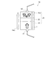
図1は、本発明の第1の実施形態に係るスピントルク発振子の構成を例示する模式的断面図である。
図1に表したように、本発明の第1の実施形態に係るスピントルク発振子10は、発振層(第1の磁性体層)10aと、スピン注入層(第2の磁性体層)30と、発振層10aとスピン注入層30との間に設けられた中間層22を有する積層構造体25を有する。
(First embodiment)
FIG. 1 is a schematic cross-sectional view illustrating the configuration of a spin torque oscillator according to the first embodiment of the invention.
As shown in FIG. 1, the
そして、スピントルク発振子10は、積層構造体25の積層方向に通電可能な1対の電極、すなわち、第1電極41及び第2電極42を有することができる。すなわち、第1電極41及び第2電極42によって、駆動電流Iが積層構造体25に通電される。
The
ただし、これらの第1及び第2の電極41、42の少なくともいずれかは、例えば、後述する磁気記録ヘッドの例えば主磁極及びリターンパス(シールド)等と兼用されても良く、この場合は、スピントルク発振子10の上記の第1及び第2の電極41、42の少なくともいずれかは省略可能である。以下では、スピントルク発振子10が、第1及び第2の電極41、42を有する場合として説明する。
However, at least one of the first and
なお、図1に表したように、積層構造体25には外部磁界Hexが印加される。
As shown in FIG. 1, an external magnetic field Hex is applied to the laminated
本実施形態に係るスピントルク発振子10においては、発振層10aは、Fe−Co−Al合金を含む。すなわち、本実施形態に係るスピントルク発振子10は、スピンFe−Co−Alを含む層を含む第1の磁性体層10aと、第2の磁性体層30と、第1の磁性体層10aと第2の磁性体層30との間に設けられた中間層22と、を備える。なお、本実施形態に係るスピントルク発振子10において、発振層10a(第1の磁性体層10a)が1層の磁性体層からなり、その磁性体層がFe−Co−Al合金を含んでも良い。また、発振層10a(第1の磁性体層10a)が、複数の層からなり、その複数の層の少なくとも1つの層が、Fe−Co−Al合金を含んでも良い。なお、本願明細書において、「Fe−Co−Al合金」は、「FeCoAl合金」と省略して記述されることがある。
In the
スピントルク発振子10は、図示しない適切な基板の上や下地の上に形成され、図示しないアルミナやSiO2等の絶縁体により、他の回路と分離される。
The
第1及び第2の電極41、42には、Ti、Cuなどの電気抵抗が低く、酸化されにくい材料を用いることができる。また、第1の電極41のうち、第1の磁性体層10aとの界面はCuにすることが望ましい。これは、界面をCuとすることで、第1の磁性体層10aを構成するAl原子の拡散防止層として働き、Al原子が第1の電極41へ拡散することを防ぐことが可能となるためである。
The first and
本実施形態に係るスピントルク発振子10においては、発振層10aには以下の組成比率のFe−Co−Al合金が用いられている。すなわち、FeとCoとの比率(Fe:Co)が、50原子パーセント(原子百分率):50原子パーセントであり、そのFeとCoの混合部物と、Alと、の比率(FeCo:Al)が、68原子パーセント:32原子パーセントである。以下、この比率を、「(Fe50at%Co50at%)68at%Al32at%」と記述する。なお、この材料の飽和磁化Msは、600emu/ccである。また、この発振層10aの層厚は、12nmである。
そして、中間層22には、層厚が3nmのCuが用いられている。
また、一方、スピン注入層30には、層厚が20nmの、CoとPtとの比率(Co:Pt)が、80原子パーセント:20原子パーセントの合金(Co80at%Pt20at%合金)が用いられている。このCo80at%Pt20at%合金は、垂直異方性を有する。なお、スピントルク発振子10の素子のサイズは、70nm四方である。
In the
The
On the other hand, for the
ただし、本実施形態に係るスピントルク発振子10は、上記の材料及び層厚だけでなく、各種の材料と層厚を有することができる。
However, the
例えば、中間層22には、例えば、Cu、Au、Agなどのスピン透過率の高い材料を用いることができる。中間層22の層厚は、1原子層から3nmとすることが望ましい。これにより発振層10aとスピン注入層30の交換結合を最適な値に調節することが可能となる。
For example, the
また、スピン注入層30には、例えば、膜面直方向に磁化配向したCoCrPt、CoCrTa、CoCrTaPt、CoCrTaNb等のCoCr系磁性、TbFeCo等のRE−TM系アモルファス合金磁性層、Co/Pd、Co/Pt、CoCrTa/Pd等のCo人工格子磁性層、CoPt系やFePt系の合金磁性層、SmCo系合金磁性層など、垂直配向性に優れた材料、CoFe、CoNiFe、NiFe、CoZrNb、FeN、FeSi、FeAlSi等の、比較的、飽和磁束密度の大きく膜面内方向に磁気異方性を有する軟磁性層や、CoFeSi、CoMnSi、CoMnAl等のグループから選択されるホイスラー合金、膜面内方向に磁化が配向したCoCr系の磁性合金膜も適宜用いることができる。さらに、複数の上記材料を積層したものを用いてもよい。
The
また、発振層10aには、FeCoAl合金と、上記のスピン注入層30に用いることができる各種の材料を積層したものを用いても良い。
なお、発振層10aには、FeCoAl合金に、さらに、Si、Ge、Mn、Cr、Bの少なくともいずれか1つ以上を添加した材料を用いても良い。さらに、発振層10aには、FeCoAl合金におけるAlの替わりに、Si、Ge、Mn、Cr、Bのいずれか1つ以上を用いた、FeCoSi、FeCoGe、FeCoMn、FeCoCr、FeCoB合金を用いても良い。これにより、例えば、発振層10aとスピン注入層30との飽和磁束密度(Bs)、異方性磁界(Hk)、及び、スピントルク伝達効率を調整することができる。
このように、本実施形態のスピントルク発振子10においては、発振層10aは、Fe−Co−(Al、Si、Ge、Mn、Cr、B)合金を含む。なお、「Fe−Co−(Al、Si、Ge、Mn、Cr、B)合金」は、Feと、Coと、Al、Si、Ge、Mn、Cr及びBの少なくともいずれかと、を含む合金である。
In addition, the
For the
Thus, in the
なお、発振層10aの層厚は、5nmから20nmとすることが望ましく、スピン注入層30の層厚は、2nmから60nmとすることが望ましい。また、スピントルク発振子10の素子のサイズは10nm四方から100nm四方にすることが望ましく、素子形状も直方体だけでなく、円柱状や六角柱状としてもよい。
Note that the layer thickness of the
図2は、本発明の第1の実施形態に係るスピントルク発振子の特性を例示するグラフ図である。
すなわち、同図(a)は、スピントルク発振子10を流れる電流の電流密度が低い場合、すなわち、駆動電流Iの電流密度Jが0.2×10⁸A/cm2の時のRH曲線であり、同図(b)は、スピントルク発振子10を流れる電流の電流密度が高い場合、すなわち、駆動電流Iの電流密度Jが1.5×108A/cm2の時のRH曲線である。これらの図において、横軸は、スピントルク発振子10に印加される外部磁界Hexを表し、縦軸は、積層構造体25を流れる電流における抵抗変化(第1電極41と第2電極42との間の抵抗の変化)を表す。なお同図(b)では、Hex=0での値が、同図(a)と等しくなるよう、値をずらしている。
また、同図(c)、(d)は、同図(a)の点A、点Bの状態における磁化の状態をそれぞれ示す模式的断面図である。また、同図(e)は、同図(b)の点Cの状態における磁化の状態を示す模式的断面図である。
FIG. 2 is a graph illustrating characteristics of the spin torque oscillator according to the first embodiment of the invention.
That is, FIG. 5A is an RH curve when the current density of the current flowing through the
FIGS. 7C and 7D are schematic cross-sectional views showing the states of magnetization in the states of points A and B in FIG. FIG. 5E is a schematic cross-sectional view showing the state of magnetization in the state of point C in FIG.
図2(a)に表したように、低電流密度の時は、典型的な保磁力差型のRH曲線となっており、スピントルクの影響はない。すなわち、同図(a)における点Aの状態、すなわち、外部磁界が零の時は、発振層10aの形状異方性により、同図(c)に表したように、発振層10aの磁化の方向は、層面に対して平行方向となっている。そして、同図(a)における点Bの状態、すなわち、外部磁界が大きい時は、同図(d)に表したように、発振層10aの磁化の方向は、外部磁界の方向と略同一方向となっている。
As shown in FIG. 2A, when the current density is low, a typical coercivity difference type RH curve is obtained, and there is no influence of the spin torque. That is, when the state at point A in FIG. 10A, that is, when the external magnetic field is zero, the magnetization anisotropy of the
一方、図2(b)に表したように、電流密度Jが大きいと、RH曲線は谷型となる。このことは、発振層10aが発振していることを表している。すなわち、すなわち、同図(b)における点Cの状態、すなわち、外部磁界が大きい時、同図(e)に表したように、発振層10aの磁化の方向は、スピントルクによって、外部磁界に対して逆向きとなり、磁化が回転している。すなわち、スピントルク発振子10の駆動電流によるスピントルクにより、発振層10aの磁化が発振している。
On the other hand, as shown in FIG. 2B, when the current density J is large, the RH curve has a valley shape. This indicates that the
このように、本実施形態に係るスピントルク発振子10は、例えば、低電流密度Jが0.2×10⁸A/cm2の時は発振しないが、電流密度Jが1.5×108A/cm2の時には、適正な発振を示す。
Thus, for example, the
(第1の比較例)
図3は、第1の比較例のスピントルク発振子の特性を例示するグラフ図である。
第1の比較例のスピントルク発振子は、発振層10aとして、CoFeを用いたものである。これ以外は、本実施形態に係るスピントルク発振子10と同様なので説明を省略する。なお、CoFeの飽和磁化Msは、1400emu/ccであり、本実施形態に係るスピントルク発振子10の発振層10aに用いられているFeCoAl合金の600emu/ccに比べて大きい。また、図3は、第1の比較例のスピントルク発振子の駆動電流の電流密度Jが1.5×108A/cm2の時の結果である。
(First comparative example)
FIG. 3 is a graph illustrating characteristics of the spin torque oscillator of the first comparative example.
The spin torque oscillator of the first comparative example uses CoFe as the
図3に表したように、第1の比較例のスピントルク発振子の場合、駆動電流Iの電流密度Jが1.5×10⁸A/cm2と、比較的大きいにもかかわらず発振現象を示していない。すなわち、図2(a)に例示した、本実施形態に係るスピントルク発振子10における電流密度Jが低い場合(Jが0.2×108A/cm2)のRH曲線に類似のRH曲線を示している。
As shown in FIG. 3, in the case of the spin torque oscillator of the first comparative example, the oscillation phenomenon despite the relatively high current density J of the drive current I of 1.5 × 10 8 A / cm 2. Not shown. That is, the RH curve similar to the RH curve when the current density J in the
なお、マイクロマグネティクス法によるシミュレーションによると、第1の比較例のように発振層10aに例えばCoFeを用いた場合には、RH曲線が谷型となる電流密度J、すなわち、発振現象を示す電流密度Jは、5.6×10⁸A/cm2であった。このように、第1の比較例のスピントルク発振子においては、発振するためには5.6×108A/cm2と非常に大きい電流を必要とする。しかし、この電流は非常に大きいため、ジュール熱による発熱が非常に大きく、素子特性が劣化してしまうため、実用上、この電流を通電することは非常に困難である。このためCoFeを発振層10aに適用した場合には、安定して発振することが困難である。
According to the simulation by the micromagnetic method, when CoFe is used for the
これに対し、本実施形態に係るスピントルク発振子10は、低電流密度(例えば電流密度Jが1.5×10⁸A/cm2)でも発振し易い特性を発揮する。すなわち、本実施形態に係るスピントルク発振子10は、第1の比較例のスピントルク発振子に比べて、約1/4の電流密度で発振が可能である。
On the other hand, the
このように、本実施形態に係るスピントルク発振子10によれば、低電流密度で安定して発振が可能であり、かつ、面内高周波磁界の強度の高いスピントルク発振子が提供できる。
Thus, according to the
本実施形態に係るスピントルク発振子10では、スピン注入層30として垂直磁化膜を用いており、これにより、スピントルクの伝達効率が向上したものと考えられる。
In the
すなわち、垂直磁化膜をスピン注入層30に用いた場合、発振層10aの磁化の軌跡が通る平面と、スピン注入層30の磁化方向は略垂直となり、発振層10aの磁化方向とスピン注入層30の磁化方向とがなす角は、常に略垂直となる。このため、常に安定したスピントルク伝達が行われる。
That is, when a perpendicular magnetization film is used for the
一方、スピン注入層30が面内磁化膜の場合、発振層10aの磁化の軌跡が通る平面と、スピン注入層30の磁化方向は略平行となる。このため、発振層10aの磁化方向とスピン注入層30の磁化方向がなす角は、瞬間瞬間によって変動する。その結果、ある瞬間はスピントルク伝達効率が高いが、ある瞬間は小さくなり、時間平均をとると、スピントルク伝達効率は大きく低下することになる。
On the other hand, when the
従って、スピン注入層30に垂直磁化膜を用いた方が、スピントルク伝達効率が高く、低電流密度での安定した発振が可能となる。
Therefore, the use of the perpendicular magnetization film for the
従って、本実施形態のスピントルク発振子10において、スピン注入層30は、垂直磁化膜を含むことが望ましい。
Therefore, in the
図4は、本発明の第1の実施形態に係るスピントルク発振子における特性を例示するグラフ図である。
すなわち、同図は、発振層10aの磁化の回転の開き角が180度となる時の臨界電流密度Jcと、発振層10aの飽和磁化Ms及び層厚tとの関係の実験結果を例示するグラフである。同図(a)の横軸は、発振層10aの飽和磁化Msを表し、同図(b)の横軸は発振層10aの層厚tを表す。そして、同図(a)、(b)の縦軸は、発振層10aの層厚方向の全ての領域において均一に、磁化の回転の開き角が180度となる時の臨界電流密度の平均値Jcの絶対値を表す。
FIG. 4 is a graph illustrating characteristics of the spin torque oscillator according to the first embodiment of the invention.
That is, this figure is a graph illustrating the experimental results of the relationship between the critical current density Jc when the rotation angle of the magnetization of the
図4(a)、(b)に表したように、臨界電流密度Jcの飽和磁化層Ms依存性は、層厚t依存性よりも大きい。すなわち、臨界電流密度Jcの飽和磁化Msに対する傾きは、臨界電流密度Jcの層厚tに対する傾きの約2倍となっている。すなわち、臨界電流密度Jcは、発振層10aの層厚tに比例し、飽和密度Msの2乗に比例する。すなわち、臨界電流密度Jcは、tMs2に比例する。
4A and 4B, the dependency of the critical current density Jc on the saturation magnetic layer Ms is larger than the dependency on the layer thickness t. That is, the gradient of the critical current density Jc with respect to the saturation magnetization Ms is about twice the gradient of the critical current density Jc with respect to the layer thickness t. That is, the critical current density Jc is proportional to the layer thickness t of the
スピントルク発振子10において、発振層10aの媒体対向面に発生する磁荷量によって高周波磁界Hacが作られる。このため、発振層10aが均一に大きな角度で回転する場合(磁化の回転の開き角が180度となる場合)、高周波磁界の強度Hacは、発振層10aの層厚tと飽和磁化Msとの積(tMs)に比例すると考えられる。
In the
その結果、発振層10aの飽和磁化Msが小さい場合は、層厚tを厚くしないと、高周波磁界アシスト記録に必要な高い強度の、高周波磁界の強度Hacが得られない。
As a result, when the saturation magnetization Ms of the
従って、本実施形態に係る発振層10aでは、発振層10aの飽和磁化Msの低い材料を用いることで臨界電流密度Jcの低減を図り、そして、発振層10aの層厚tを実用的に可能な範囲で増大することで高周波磁界の強度Hacの増加を図る必要がある。
Therefore, in the
図5は、本発明の第1の実施形態に係るスピントルク発振子に用いられるFeCoAl合金の特性を例示するグラフ図である。
すなわち、同図は、第1の実施形態に用いることができるFeCoAl合金におけるAl組成比率と、飽和磁化Msと、の関係を例示している。同図において、横軸はFeCoAl合金におけるAl組成比率を表し、縦軸は飽和磁化Msを表す。
なお、同図には、比較例である、FeCoの飽和磁化の値と、NiFeの飽和磁化の値とを破線で示している。
FIG. 5 is a graph illustrating characteristics of the FeCoAl alloy used in the spin torque oscillator according to the first embodiment of the invention.
That is, this figure illustrates the relationship between the Al composition ratio in the FeCoAl alloy that can be used in the first embodiment and the saturation magnetization Ms. In the figure, the horizontal axis represents the Al composition ratio in the FeCoAl alloy, and the vertical axis represents the saturation magnetization Ms.
In the figure, the saturation magnetization value of FeCo and the saturation magnetization value of NiFe, which are comparative examples, are indicated by broken lines.
図5に表したように、FeCoAl合金において、Al組成比率の増加により、飽和磁化Msは減少し、Al組成比率が24原子パーセント以上では、NiFeの飽和磁化の値以下となる。 As shown in FIG. 5, in the FeCoAl alloy, the saturation magnetization Ms decreases as the Al composition ratio increases. When the Al composition ratio is 24 atomic percent or more, the saturation magnetization Ms becomes less than the saturation magnetization value of NiFe.
スピントルクは、中間層22と発振層10aとの界面で受け渡されるため、発振層10aの層厚tが過度に厚い場合、界面付近では、磁化の回転の開き角が180度となる大きな回転を示すが、界面から離れた領域では大きな回転ができないことが生じる。このため、層厚tを厚くしても、高周波磁界の強度Hacは大きくは増加しないことが発生し得る。
このため、発振層10aの層厚方向の全ての領域において、均一に、大きな角度で回転する(磁化の回転の開き角が180度となる)には、発振層10aの層厚tは、30nm以下にする必要がある。
Since the spin torque is transferred at the interface between the
For this reason, in all regions in the layer thickness direction of the
このため、発振層10aに飽和磁化Msが低い材料を用いたときに、必要な高周波磁界の強度Hacを必要な強度とするために、その材料の飽和磁化Msは、500emu以上とする必要がある。従って、図5に例示した飽和磁化MsのAl組成比率依存性の実験結果から、Al組成比率は、40原子パーセント以下とすることが望ましい。
For this reason, when a material having a low saturation magnetization Ms is used for the
一方、発振層10aの飽和磁化Msは、700emu/cc〜1000emu/ccが最適である。この時、発振層10aの層厚tは、10nm〜25nmとなり、発振層10aの層厚方向の全ての領域において、大きな角度で回転する(磁化の回転の開き角が180度となる)ことが可能である。すなわち、このとき、高周波磁界の強度Hacを最も効率的に大きくすることができる。
このため、Al組成比率は、20原子パーセント〜30原子パーセントであることがより望ましい。
On the other hand, the saturation magnetization Ms of the
For this reason, the Al composition ratio is more preferably 20 atomic percent to 30 atomic percent.
一方、既に図4に関して説明したように、発振層10aの飽和磁化Msが増加すると、臨界電流密度Jc(駆動電流I)は、Msの2乗に比例して増加する。さらに、スピントルク発振子10の素子のジュール熱による発熱は、駆動電流Iの2乗に比例して増加する。このため、素子のジュール熱による発熱は、飽和磁化Msの4乗に比例して増加することになる。この時、飽和磁化Msが1300emu/ccよりも大きいとき、素子の発熱により素子特性が劣化するため、利用することが難しい。
On the other hand, as already described with reference to FIG. 4, when the saturation magnetization Ms of the
従って、発振層10aの飽和磁化Msは、1300emu/cc以下とすることが望ましい。従って、図5に例示した飽和磁化MsのAl組成比率依存性の実験結果から、Al組成比率は、12原子パーセント以上とすることが望ましい。
Therefore, the saturation magnetization Ms of the
スピントルク発振子におけるスピントルク効果の原理と、CPP−GMR(Current Perpendicular to Plane - Giant Magneto-Resistive)効果の原理と、は、同一の起源により発生していると考えられている。すなわち、反平行状態に磁化した2枚の磁性体層とその間に設けられた中間層からなる積層構造体において、最初の磁性層の磁化方向にスピン分極した伝導電子が、中間層を経由して、もう一方の磁性層に流入する現象を考える。このとき、最初の磁性層の磁化方向にスピン分極した伝導電子は、もう一方の磁性層に流入する際にスピン散乱し、抵抗が増加すると同時に、スピン角運動量をスピントルクとして受け渡すことになる。このため、MR比の増加が、スピントルク伝達効率の増加に直結する。 It is considered that the principle of the spin torque effect in the spin torque oscillator and the principle of the CPP-GMR (Current Perpendicular to Plane-Giant Magneto-Resistive) effect are generated from the same origin. That is, in a laminated structure composed of two magnetic layers magnetized antiparallel to each other and an intermediate layer provided therebetween, conduction electrons spin-polarized in the magnetization direction of the first magnetic layer pass through the intermediate layer. Consider the phenomenon of flowing into the other magnetic layer. At this time, conduction electrons spin-polarized in the magnetization direction of the first magnetic layer are spin-scattered when flowing into the other magnetic layer, and the resistance increases, and at the same time, the spin angular momentum is transferred as spin torque. . For this reason, an increase in MR ratio is directly linked to an increase in spin torque transmission efficiency.
このため、GMR効果が大きい材料を発振層およびスピン注入層界面に用いることが望ましい。このため、本実施形態に係るスピントルク発振子10の発振層10aに用いるFeCo−(Al、Si、Ge、Mn、Cr、B)合金におけるFeCoの組成は、結晶構造がbcc構造となる組成、すなわち、Fe組成が20原子パーセント以上であることが望ましい。
For this reason, it is desirable to use a material having a large GMR effect for the interface between the oscillation layer and the spin injection layer. For this reason, the composition of FeCo in the FeCo- (Al, Si, Ge, Mn, Cr, B) alloy used for the
以上のように、本実施形態に係るスピントルク発振子10において、発振層10aに用いるFeCoAl合金において、Al組成比率を10原子パーセント〜40原子パーセントとすることで、良好な高周波磁界の強度が達成可能かつ、低駆動電流で発振可能な、スピントルク発振素子を製作することが可能となる。
As described above, in the
なお、特許文献5においては、フリー層にFeCoAl合金を利用している。しかし、特許文献5に開示された技術は、TMRを利用した面内磁化型メモリ応用であり、GMRを利用したスピントルク発振子への応用を目的とした本発明とは、異なる。また、特許文献6では、ホイッスラー合金の利用を想定し、組成もCo2FeAlに限定しており、本実施形態にスピントルク発振子10とは、FeCoの組成が大きく異なっている。また、非特許文献3では、面内磁化膜CPP−GMRヘッド応用において、FeCoAlによるJcの低減について記載されているが、この効果はJc∝tMs2で説明可能であり、本実施形態に係るスピントルク発振子10では、垂直磁化膜を用いたスピントルク発振素子であり、Jc∝tMs2で説明不可能な新たに見いだされた効果により、Jcの低減が可能となっている。
In Patent Document 5, an FeCoAl alloy is used for the free layer. However, the technique disclosed in Patent Document 5 is an in-plane magnetization type memory application using TMR, and is different from the present invention aimed at application to a spin torque oscillator using GMR. In Patent Document 6, the use of a Whistler alloy is assumed, and the composition is also limited to
(第2の実施の形態)
図6は、本発明の第2の実施形態に係るスピントルク発振子の構成を例示する模式的断面図である。
図6に表したように、本発明の第2の実施形態に係るスピントルク発振子10bにおいては、スピン注入層30として、層厚2nmの(Fe50at%Co50at%)76at%Al24at%合金(第1スピン注入層30a)と、層厚20nmのCoPt層(第2スピン注入層30b)30bと、の積層膜が用いられている。FeCoAl層である第1スピン注入層30aは、中間層22との界面、すなわち、発振層10aの側に設けられている。発振層10aには、層厚が12nmの(Fe50at%Co50at%)84at%Al16at%合金が用いられている。
(Second Embodiment)
FIG. 6 is a schematic cross-sectional view illustrating the configuration of the spin torque oscillator according to the second embodiment of the invention.
As shown in FIG. 6, in the
これ以外は、第1の実施形態に係るスピントルク発振子10と同様である。すなわち、中間層22には、層厚が3nmのCuが用いられている。なお、スピントルク発振子10の素子のサイズは、70nm四方である。
The rest is the same as the
このような構成を有する本実施形態に係るスピントルク発振子10bは、6kOeの外部磁界の印加の状態において、電流密度Jが1.4×10⁸A/cm2の場合に、良好に発振する。すなわち、スピントルク発振子10bの発振層10aは、磁化の回転の開き角が180度となる大きな回転を示す。
The
図7は、本発明の第2の実施形態に係るスピントルク発振子の特性を例示するグラフ図である。
すなわち、同図は、本発明の第2の実施形態に係るスピントルク発振子10bにおいて、各磁性体層の面内磁化成分の発振スペクトルを例示している。同図の横軸は、発振周波数であり、縦軸は面内磁化成分の発振強度である。
FIG. 7 is a graph illustrating characteristics of the spin torque oscillator according to the second embodiment of the invention.
That is, this figure illustrates the oscillation spectrum of the in-plane magnetization component of each magnetic layer in the
図7に表したように、本実施形態に係るスピントルク発振子10bは、19GHzにシャープなピークを有する。このことから、発振層10aは非常に安定して発振していることがわかる。
As shown in FIG. 7, the
このように、発振層10a、及び、スピン注入層30の中間層との界面に、FeCoAl合金からなる第1スピン注入層30aを設けることで、スピントルク伝達効率がさらに向上する。すなわち、従来のCoFe/NiFeを用いた発振層やCoPtを用いたスピン注入層よりも、スピントルク伝達効率の向上が可能となる。
Thus, by providing the first
これにより、本実施形態に係るスピントルク発振子10bによれば、低電流密度で安定して発振が可能であり、かつ、面内高周波磁界の強度の高いスピントルク発振子が提供できる。
Thereby, according to the
ところで、スピン注入層30の中間層との界面にFeCoAl合金からなる第1スピン注入層30aを設けた場合に、面内磁化膜であるFeCoAl合金が垂直に磁化するかどうかが懸念されるが、FeCoAl合金が低Msであること、第1スピン注入層30aの層厚を2nmと薄くしたこと、及び、第1スピン注入層30aのFeCoAl層と、第2スピン注入層30bのCoPt合金層との交換結合力が十分に大きいこと、によって、面内磁化膜であるFeCoAl合金が垂直に磁化することが実現可能になっている。なお、第1スピン注入層30aの膜厚が5nm以下とすることが望ましく、この時、第2スピン注入層30bの異方性エネルギーおよび、第1スピン注入層30aと第2スピン注入層30aとの間の交換結合力を調整することにより、第1スピン注入層30aを垂直に磁化することが可能となる。
By the way, when the first
また、スピン注入層30の中間層との界面にFeCoAl合金からなる第1スピン注入層30aを設けた場合に、スピントルク伝達効率を十分に大きくできるかどうかが懸念される。FeCoAl合金のスピン拡散長が短いため、第1スピン注入層30aのFeCoAl合金が薄い場合でも伝導電子はスピン分極する。この結果、第1スピン注入層30aのFeCoAl層が薄い場合でも、スピントルク伝達効率を十分に大きくできる。このため、第1スピン注入層30aの膜厚は0.5nm以上であればよい。
In addition, there is a concern whether the spin torque transmission efficiency can be sufficiently increased when the first
以上より、第1スピン注入層30aのFeCoAl合金の膜厚は0.5nmから5nmとすることが望ましい。
From the above, it is desirable that the film thickness of the FeCoAl alloy of the first
ただし、本実施形態に係るスピントルク発振子10bにおいても、上記の材料及び層厚だけでなく、各種の材料と層厚を有することができる。
However, the
例えば、中間層22には、例えば、Cu、Au、Agなどのスピン透過率の高い材料を用いることができる。中間層22の層厚は、1原子層から3nmとすることが望ましい。これにより発振層10aとスピン注入層30の交換結合を最適な値に調節することが可能となる。
For example, the
また、スピン注入層30の第2スピン注入層30bには、例えば、膜面直方向に磁化配向したCoCrPt、CoCrTa、CoCrTaPt、CoCrTaNb等のCoCr系磁性、TbFeCo等のRE−TM系アモルファス合金磁性層、Co/Pd、Co/Pt、CoCrTa/Pd等のCo人工格子磁性層、CoPt系やFePt系の合金磁性層、SmCo系合金磁性層など、垂直配向性に優れた材料、CoFe、CoNiFe、NiFe、CoZrNb、FeN、FeSi、FeAlSi等の、比較的、飽和磁束密度の大きく膜面内方向に磁気異方性を有する軟磁性層や、CoFeSi、CoMnSi、CoMnAl等のグループから選択されるホイスラー合金、膜面内方向に磁化が配向したCoCr系の磁性合金膜も適宜用いることができる。さらに、複数の上記材料を積層したものを用いてもよい。
The second
また、発振層10aには、FeCoAl合金と、上記のスピン注入層30の第2スピン注入層30bに用いることができる各種の材料を積層したものを用いても良い。
なお、発振層10aおよび第1スピン注入層30aには、FeCoAl合金に、さらに、Si、Ge、Mn、Cr、Bの少なくともいずれか1つ以上を添加した材料を用いても良い。さらに、発振層10aおよび第1スピン注入層30aには、FeCoAl合金におけるAlの替わりに、Si、Ge、Mn、Cr、Bのいずれか1つ以上を用いた、FeCoSi、FeCoGe、FeCoMn、FeCoCr、FeCoB合金を用いても良い。これにより、例えば、発振層10aとスピン注入層30との飽和磁束密度(Bs)、異方性磁界(Hk)、及び、スピントルク伝達効率を調整することができる。
In addition, the
The
すなわち、本実施形態に係るスピントルク発振子10bにおいては、発振層10aは、Fe−Co−(Al、Si、Ge、Mn、Cr、B)合金を含み、スピン注入層30の中間層22の側の部分は、Fe−Co−(Al、Si、Ge、Mn、Cr、B)合金を含む。
That is, in the
なお、発振層10aの層厚は、5nmから20nmとすることが望ましく、スピン注入層30の層厚は、2nmから60nmとすることが望ましい。また、Siは、アニールする際にFeCo合金母相から拡散しにくい、という特徴がある。このため、素子プロセスでアニールが必要な場合や、第1スピン注入層30aに用いる場合には、FeCoSi合金を用いることが望ましい。
Note that the layer thickness of the
(第3の実施の形態)
図8は、本発明の第3の実施形態に係るスピントルク発振子の構成を例示する模式的断面図である。
図8に表したように、本発明の第3の実施形態に係るスピントルク発振子10cにおいては、スピン注入層30として、中間層側のFeCoAl層(第1スピン注入層30a)と、層厚20nmのCoPt層(第2スピン注入層30b)30bと、の積層膜が用いられている。また、本実施形態に係るスピントルク発振子においては、発振層10aはFeCoAl合金を含んでいない。
(Third embodiment)
FIG. 8 is a schematic cross-sectional view illustrating the configuration of a spin torque oscillator according to the third embodiment of the invention.
As shown in FIG. 8, in the
すなわち、スピン注入層30は、FeCoAl合金層と、膜面垂直方向に磁化配向したCoPt合金層と、の積層構造からなっており、中間層22との界面に、FeCoAl合金層が配置されている。すなわち、スピン注入層30は、膜面垂直方向に磁化配向したCoPt合金を含む第2スピン注入層30bと、第2スピン注入層30bと中間層22との間に配置され、FeCoAl合金を含む第1スピン注入層30aと、を有している。
第1スピン注入層30aとなるFeCoAl合金層の層厚は、0.5nmから5nmであることが望ましい。
一方、第2スピン注入層30bとなるCoPt合金の層厚は、2nmから60nmとすることが望ましい。
なお、第1スピン注入層30aの層厚と、第2スピン注入層30bの層厚とは、第1スピン注入層30aとなるFeCoAl合金によりスピントルクが十分に発振層に伝達し、かつ、第2スピン注入層30bとなるCoPt合金の垂直磁気異方性によりFeCoAl合金層が垂直に磁化するように、適宜調整することができる。
That is, the
The thickness of the FeCoAl alloy layer serving as the first
On the other hand, the thickness of the CoPt alloy to be the second
The thickness of the first
なお、第1スピン注入層30aに用いられるFeCoAl合金は、Si、Ge、Mn、Cr、Bのうちのいずれか1つ以上を含むこともできる。
さらに、第1スピン注入層30aに用いられるFeCoAl合金のAlの替わりに、Si、Ge、Mn、Cr、Bをいずれか1つ以上用いた、FeCoSi、FeCoGe、FeCoMn、FeCoCr、FeCoB合金を、第1スピン注入層30aに用いても良い。
すなわち、本実施形態に係るスピントルク発振子10cにおいては、スピン注入層30の中間層22との界面では、Fe−Co−(Al、Si、Ge、Mn、Cr、B)合金を含む。
Note that the FeCoAl alloy used for the first
Further, instead of Al of the FeCoAl alloy used for the first
That is, the
一方、発振層10aには、発振時に磁界を発生する高Bs軟磁性材料(FeCo/NiFe積層膜)を用いることができ、発振層10aの層厚は5nmから20nmとすることが望ましい。
On the other hand, a high Bs soft magnetic material (FeCo / NiFe laminated film) that generates a magnetic field during oscillation can be used for the
また、第2スピン注入層30b、及び、発振層10aには、CoFe、CoNiFe、NiFe、CoZrNb、FeN、FeSi、FeAlSi等の、比較的、飽和磁束密度の大きく膜面内方向に磁気異方性を有する軟磁性層や、CoFeSi、CoMnSi、CoMnAl等のグループから選択されるホイスラー合金、膜面内方向に磁化が配向したCoCr系の磁性合金膜を用いることができる。さらに、膜面直方向に磁化配向したCoCrPt、CoCrTa、CoCrTaPt、CoCrTaNb等のCoCr系磁性、TbFeCo等のRE−TM系アモルファス合金磁性層、Co/Pd、Co/Pt、CoCrTa/Pd等のCo人工格子磁性層、CoPt系やFePt系の合金磁性層、SmCo系合金磁性層など、垂直配向性に優れた材料も適宜用いることができる。
Further, the second
また、第2スピン注入層30b、及び、発振層10aにおいては、複数の上記材料を積層してもよい。これにより、発振層10aとスピン注入層30との飽和磁束密度(Bs)及び異方性磁界(Hk)を調整することができる。
In the second
また、第1、第2の電極41、42としては、Ti、Cuなどの電気抵抗が低く、酸化されにくい材料を用いることができる。
また、中間層22としては、Cu、Au、Agなどのスピン透過率の高い材料を用いることができる。中間層22の層厚は、1原子層から3nmとすることが望ましい。これにより発振層とスピン注入層の交換結合を最適な値に調節することが可能となる。
The first and
The
このような構造を有する本実施形態に係るスピントルク発振子10cにおいては、スピン注入層30の中間層との界面に、FeCoAl合金からなる第1スピン注入層30aを設けることで、スピントルク伝達効率が向上する。
In the
これにより、本実施形態に係るスピントルク発振子10cによれば、低電流密度で安定して発振が可能であり、かつ、面内高周波磁界の強度の高いスピントルク発振子が提供できる。
Thereby, according to the
ところで、スピン注入層30の中間層側の界面にFeCoAl合金からなる第1スピン注入層30aを設けた場合において、FeCoAl合金が低Msであること、第1スピン注入層30aの層厚を2nmと薄くしたこと、及び、第1スピン注入層30aのFeCoAl層と、第2スピン注入層30bのCoPt合金層との交換結合力が十分に大きいこと、によって、面内磁化膜であるFeCoAl合金が垂直に磁化することが実現可能である。また、FeCoAl合金のスピン拡散長が短いため、スピントルク伝達効率を十分に大きくできる。
By the way, when the first
(第4の実施の形態)
本発明の第4の実施の形態に係る磁気記録ヘッドについて、多粒子系の垂直磁気記録媒体に記録する場合を想定して、説明する。
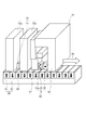
図9は、本発明の第4の実施形態に係る磁気記録ヘッドの構成を例示する模式的斜視図である。
図10は、本発明の第4の実施形態に係る磁気記録ヘッドが搭載されるヘッドスライダーの構成を例示する模式的斜視図である。
図11は、本発明の第4の実施形態に係る磁気記録ヘッドに用いられるスピントルク発振子の構成を例示する模式的斜視図である。
(Fourth embodiment)
A magnetic recording head according to a fourth embodiment of the present invention will be described on the assumption that recording is performed on a multi-particle perpendicular magnetic recording medium.
FIG. 9 is a schematic perspective view illustrating the configuration of a magnetic recording head according to the fourth embodiment of the invention.
FIG. 10 is a schematic perspective view illustrating the configuration of a head slider on which a magnetic recording head according to the fourth embodiment of the invention is mounted.
FIG. 11 is a schematic perspective view illustrating the configuration of a spin torque oscillator used in a magnetic recording head according to the fourth embodiment of the invention.
図9に表したように、本発明の第4の実施形態に係る磁気記録ヘッド51は、主磁極61と、上記の本発明の実施形態に係るスピントルク発振子10と、を備える。
As shown in FIG. 9, the
なお、本具体例では、スピントルク発振子として、第1の実施形態に係るスピントルク発振子10が用いられているが、本発明はこれに限らず、第2及び第3の実施形態に係るスピントルク発振子10b、10c、及び、それらを変形した各種のスピントルク発振子を用いることができる。以下に説明する具体例では、スピントルク発振子として第1の実施形態に係るスピントルク発振子10を用いる例として説明する。
In this example, the
図9に表したように、発振層10aは、主磁極61とスピン注入層30との間に配置することができる。ただし、それとは逆に、スピン注入層30を、主磁極61と発振層10aとの間に配置しても良い。
上記の主磁極61と、スピントルク発振子10と、は、書き込みヘッド部60に含まれる。
さらに、書き込みヘッド部60は、リターンパス(シールド)62をさらに含むことができる。
As shown in FIG. 9, the
The main
Further, the
なお、主磁極61と第2の電極42は共用されており、リターンパス(シールド)62と第1の電極41は共用されている。
The main
なお、図9に表したように、本実施形態に係る磁気記録ヘッド51には、さらに、再生ヘッド部70を設けることができる。
再生ヘッド部70は、第1磁気シールド層72aと、第2磁気シールド層72bと、第1磁気シールド層72aと第2磁気シールド層72bとの間に設けられた磁気再生素子71と、を含む。
上記の再生ヘッド部70の各要素、及び、上記の書き込みヘッド部60の各要素は、図示しないアルミナ等の絶縁体により分離される。
磁気再生素子71としては、GMR素子やTMR(Tunnel Magneto-Resistive effect)素子などを利用することが可能である。なお、再生分解能をあげるために、磁気再生素子71は、2枚の磁気シールド層、すなわち、第1及び第2磁気シールド層72a、72bの間に設置される。
As shown in FIG. 9, the
The reproducing
Each element of the read
As the magnetic reproducing
そして、図9に表したように、磁気記録ヘッド51の媒体対向面61sに対向して磁気記録媒体80が設置される。そして、主磁極61は、磁気記録媒体80に記録磁界を印加する。なお、磁気記録ヘッド51の媒体対向面61sは、磁気記録ヘッド51に対して設置される磁気記録媒体80に対向した主磁極61の主面とすることができる。
また、例えば、図10に表したように、磁気記録ヘッド51は、ヘッドスライダー3に搭載される。ヘッドスライダー3は、Al2O3/TiCなどからなり、磁気ディスクなどの磁気記録媒体80の上を、浮上または接触しながら相対的に運動できるように設計され、製作される。
ヘッドスライダー3は、空気流入側3Aと空気流出側3Bとを有し、磁気記録ヘッド51は、空気流出側3Bの側面などに配置される。これにより、ヘッドスライダー3に搭載された磁気記録ヘッド51は、磁気記録媒体80の上を浮上または接触しながら相対的に運動する。
Then, as shown in FIG. 9, the
For example, as shown in FIG. 10, the
The
図9に表したように、磁気記録媒体80は、媒体基板82と、その上に設けられた磁気記録層81と、を有する。書き込みヘッド部60から印加される磁界により、磁気記録層81の磁化83が所定の方向に制御され、書き込みがなされる。なお、この時、磁気記録媒体80は、媒体移動方向85の方向に、磁気記録ヘッド51に対して相対的に移動する。
一方、再生ヘッド部70は、磁気記録層81の磁化の方向を読み取る。
As shown in FIG. 9, the
On the other hand, the reproducing
図11に表したように、本実施形態に用いられるスピントルク発振子10は、スピン注入層30と、スピン透過率の高い中間層22と、発振層10aがこの順に積層された積層構造体25を有し、積層構造体25に接続された第1電極41及び第2電極42を通じて駆動電子流を流すことにより、発振層10aから高周波磁界を発生させることができる。駆動電流密度は、所望の発振状態になるよう適宜調整する。なお、記録トラックピッチが縮小し、スピントルク発振子の素子サイズがより小さくなった場合、熱の放散が改善されるため、駆動電流密度をより改善することが可能である。
As shown in FIG. 11, the
また、スピン注入層30の保磁力は、主磁極61から印加される磁界より小さくすることが望ましい。この時、スピン注入層30の磁化方向と、主磁極61からの印加磁界方向とは略平行となる。その結果、主磁極61から発振層10aに印加される磁界と、スピン注入層30から発振層10aに印加されるスピントルクとが、主磁極61からの印加磁界方向に依存せず常につりあい、安定した発振が可能となる。このため、主磁極61が、「0」及び「1」のどちらを磁気記録媒体80に記録する場合にも、安定した高周波磁界アシスト記録が可能となる。
The coercive force of the
なお、スピン注入層30の保磁力が主磁極61から印加される磁界より大きい場合、スピン注入層30の磁化方向は、主磁極61からの印加磁界によらず、常に略同一方向に磁化する。この時、主磁極61が「0」を記録する場合には、安定した発振が可能であったとする。しかし、「1」を記録する場合、主磁極61からの磁界が反転する必要がある。この結果、主磁極61から発振層10aに印加される磁界と、スピン注入層30から発振層10aに印加されるスピントルクとがつりあわなくなり、発振が停止する。このため、安定した高周波磁界アシスト記録が不可能となる。以上の理由から、スピン注入層30の保磁力は、主磁極61から印加される磁界より小さくすることが望ましい。
When the coercive force of the
スピントルク発振子10の各構成要素に関しては、既に第1の実施形態に関して説明したので省略する。
Since each component of the
主磁極61及びリターンパス62は、FeCo、CoFe、CoNiFe、NiFe、CoZrNb、FeN、FeSi、FeAlSi等の、比較的、飽和磁束密度の大きい軟磁性層で構成されている。
The main
また、主磁極61は、媒体対向面61sの側の部分と、それ以外の部分の材料を別々の材料としても良い。すなわち、例えば、磁気記録媒体80やスピントルク発振子10に発生する磁界を大きくするため、媒体対向面61sの側の部分の材料を、飽和磁束密度の特に大きいFeCo、CoNiFe、FeN等とし、それ以外の部分は、特に透磁率が高いNiFe等にしても良い。また、磁気記録媒体80やスピントルク発振子10に発生する磁界を大きくするため、主磁極61の媒体対向面61sの側の形状を、バックギャップ部より小さくしても良い。これにより、磁束が媒体対向面61sの側の部分に集中し、高強度の磁界を発生することが可能となる。
In addition, the main
主磁極61のコイルには、Ti、Cuなどの電気抵抗が低く、酸化されにくい材料を用いることができる。
For the coil of the main
このような構成を有する本実施形態に係る磁気記録ヘッド51によれば、低電流密度で安定して発振が可能であり、かつ、面内高周波磁界の強度の高いスピントルク発振子による安定した高周波磁界が得られ、高密度の磁気記録を実現できる磁気記録ヘッドが提供できる。
According to the
なお、スピントルク発振子10の高周波磁界の強度Hacの最大領域は、発振層10aのリーディング側及びトレーリング側にある。主磁極61からの記録磁界の最大領域と、トレーリング側の高周波磁界の強度Hacの最大領域と、が重畳するように、スピントルク発振子10と、主磁極61と、シールド62の位置を調整することにより、良好な記録が可能である。
The maximum region of the high frequency magnetic field intensity Hac of the
本実施形態に係る磁気記録ヘッド51において、スピントルク発振子として第2の実施形態で説明したスピントルク発振子10bを用いることができる。
すなわち、発振層10a、及び、スピン注入層30の中間層側の界面側、に、FeCoAl合金からなる第1スピン注入層30aを設ける。これにより、スピントルク伝達効率がさらに向上する。
In the
That is, the first
従って、低電流密度でさらに安定して発振が可能であり、かつ、面内高周波磁界の強度の高いスピントルク発振子によるさらに安定した高周波磁界が得られ、高密度の磁気記録を実現できる磁気記録ヘッドが提供できる。 Therefore, a magnetic recording that can oscillate more stably at a low current density and that can provide a more stable high-frequency magnetic field by a spin torque oscillator having a high in-plane high-frequency magnetic field strength and can realize high-density magnetic recording. Head can be provided.
なお、この場合も、スピントルク発振子10bの高周波磁界の強度Hacの最大領域は、発振層10aのリーディング側及びトレーリング側にある。主磁極61からの記録磁界の最大領域と、トレーリング側の高周波磁界の強度Hacの最大領域と、が重畳するように、スピントルク発振子10bと、主磁極61と、シールド62の位置を調整することにより、良好な記録が可能である。
In this case, the maximum region of the high frequency magnetic field intensity Hac of the
さらに、本実施形態に係る磁気記録ヘッド51において、スピントルク発振子として第3の実施形態で説明したスピントルク発振子10cを用いることができる。
すなわち、スピン注入層30の中間層側の界面側に、FeCoAl合金からなる第1スピン注入層30aを設ける。これにより、スピントルク伝達効率が向上する。
Furthermore, in the
That is, the first
また、主磁極61の発振層10aとの界面をCuとすることができる。これにより、FeCoAl合金からなる発振層10aのAl原子の拡散を防止することが可能となる。その結果、良好なスピントルク発振子を作製することが可能となる。
Further, the interface between the main
従って、低電流密度で安定して発振が可能であり、かつ、面内高周波磁界の強度の高いスピントルク発振子による安定した高周波磁界が得られ、高密度の磁気記録を実現できる磁気記録ヘッドが提供できる。 Therefore, a magnetic recording head that can stably oscillate at a low current density and can obtain a stable high-frequency magnetic field by a spin torque oscillator having a high in-plane high-frequency magnetic field intensity and can realize high-density magnetic recording. Can be provided.
(第5の実施の形態)
以下、本発明の第5の実施の形態に係る磁気記録装置及び磁気ヘッドアセンブリについて説明する。
上記で説明した本発明の実施形態に係る磁気記録ヘッドは、例えば、記録再生一体型の磁気ヘッドアセンブリに組み込まれ、磁気記録装置に搭載することができる。なお、本実施形態に係る磁気記録装置は、記録機能のみを有することもできるし、記録機能と再生機能の両方を有することもできる。
(Fifth embodiment)
Hereinafter, a magnetic recording apparatus and a magnetic head assembly according to a fifth embodiment of the invention will be described.
The magnetic recording head according to the embodiment of the present invention described above can be incorporated in a recording / reproducing integrated magnetic head assembly and mounted on a magnetic recording apparatus, for example. The magnetic recording apparatus according to the present embodiment can have only a recording function, or can have both a recording function and a reproducing function.
図12は、本発明の第5の実施形態に係る磁気記録装置の構成を例示する模式的斜視図である。
図13は、本発明の第5の実施形態に係る磁気記録装置の一部の構成を例示する模式的斜視図である。
図12に表したように、本発明の第5の実施形態に係る磁気記録装置150は、ロータリーアクチュエータを用いた形式の装置である。同図において、記録用媒体ディスク180は、スピンドルモータ4に装着され、図示しない駆動装置制御部からの制御信号に応答する図示しないモータにより矢印Aの方向に回転する。本実施形態に係る磁気記録装置150は、複数の記録用媒体ディスク180を備えたものとしても良い。
FIG. 12 is a schematic perspective view illustrating the configuration of a magnetic recording apparatus according to the fifth embodiment of the invention.
FIG. 13 is a schematic perspective view illustrating the configuration of a part of the magnetic recording apparatus according to the fifth embodiment of the invention.
As shown in FIG. 12, the
記録用媒体ディスク180に格納する情報の記録再生を行うヘッドスライダー3は、既に説明したような構成を有し、薄膜状のサスペンション154の先端に取り付けられている。ここで、ヘッドスライダー3は、例えば、前述した実施の形態に係る磁気記録ヘッドをその先端付近に搭載している。
The
記録用媒体ディスク180が回転すると、サスペンション154による押付け圧力とヘッドスライダー3の媒体対向面(ABS)で発生する圧力とがつりあい、ヘッドスライダー3の媒体対向面は、記録用媒体ディスク180の表面から所定の浮上量をもって保持される。なお、ヘッドスライダー3が記録用媒体ディスク180と接触するいわゆる「接触走行型」としても良い。
When the
サスペンション154は、図示しない駆動コイルを保持するボビン部などを有するアクチュエータアーム155の一端に接続されている。アクチュエータアーム155の他端には、リニアモータの一種であるボイスコイルモータ156が設けられている。ボイスコイルモータ156は、アクチュエータアーム155のボビン部に巻き上げられた図示しない駆動コイルと、このコイルを挟み込むように対向して配置された永久磁石及び対向ヨークからなる磁気回路とから構成することができる。
The
アクチュエータアーム155は、軸受部157の上下2箇所に設けられた図示しないボールベアリングによって保持され、ボイスコイルモータ156により回転摺動が自在にできるようになっている。その結果、磁気記録ヘッドを記録用媒体ディスク180の任意の位置に移動可能となる。
The
図13(a)は、本実施形態に係る磁気記録装置の一部の構成を例示しており、ヘッドスタックアセンブリ160の拡大斜視図である。また、図13(b)は、ヘッドスタックアセンブリ160の一部となる磁気ヘッドアセンブリ(ヘッドジンバルアセンブリ)158を例示する斜視図である。
図13(a)に表したように、ヘッドスタックアセンブリ160は、軸受部157と、この軸受部157から延出したヘッドジンバルアセンブリ158と、軸受部157からヘッドジンバルアセンブリ158と反対方向に延出しているとともにボイスコイルモータのコイル162を支持した支持フレーム161を有している。
FIG. 13A illustrates a partial configuration of the magnetic recording apparatus according to the present embodiment, and is an enlarged perspective view of the
As shown in FIG. 13A, the
また、図13(b)に表したように、ヘッドジンバルアセンブリ158は、軸受部157から延出したアクチュエータアーム155と、アクチュエータアーム155から延出したサスペンション154と、を有している。
As shown in FIG. 13B, the
サスペンション154の先端には、既に説明した本発明の実施形態に係る磁気記録ヘッドを具備するヘッドスライダー3が取り付けられている。そして、既に説明したように、ヘッドスライダー3には、本発明の実施形態に係る磁気記録ヘッドが搭載される。
The
すなわち、本発明の実施形態に係る磁気ヘッドアセンブリ(ヘッドジンバルアセンブリ)158は、本発明の実施形態に係る磁気記録ヘッドと、前記磁気記録ヘッドが搭載されたヘッドスライダー3と、前記ヘッドスライダー3を一端に搭載するサスペンション154と、前記サスペンション154の他端に接続されたアクチュエータアーム155と、を備える。
That is, a magnetic head assembly (head gimbal assembly) 158 according to an embodiment of the present invention includes a magnetic recording head according to an embodiment of the present invention, a
サスペンション154は、信号の書き込み及び読み取り用、浮上量調整のためのヒーター用、スピントルク発振子用のリード線(図示しない)を有し、このリード線とヘッドスライダー3に組み込まれた磁気記録ヘッドの各電極とが電気的に接続される。また、図示しない電極パッドが、ヘッドジンバルアセンブリ158に設けられる。本具体例においては、電極パッドは8個設けられる。すなわち、主磁極61のコイル用の電極パッドが2つ、磁気再生素子71用の電極パッドが2つ、DFH(ダイナミックフライングハイト)用の電極パッドが2つ、スピントルク発振子10用の電極パッドが2つ、設けられる。
The
そして、磁気記録ヘッドを用いて磁気記録媒体への信号の書き込みと読み出しを行う信号処理部190が設けられる。信号処理部190は、例えば、図12に例示した磁気記録装置150の図面中の背面側に設けられる。信号処理部190の入出力線は、ヘッドジンバルアセンブリ158の電極パッドに接続され、磁気記録ヘッドと電気的に結合される。
A
このように、本実施形態に係る磁気記録装置150は、磁気記録媒体と、上記の実施形態に係る磁気記録ヘッドと、磁気記録媒体と磁気記録ヘッドとを離間させ、または、接触させた状態で対峙させながら相対的に移動可能とした可動部と、磁気記録ヘッドを磁気記録媒体の所定記録位置に位置合せする位置制御部と、磁気記録ヘッドを用いて磁気記録媒体への信号の書き込みと読み出しを行う信号処理部と、を備える。
As described above, the
すなわち、上記の磁気記録媒体として、記録用媒体ディスク180が用いられる。
上記の可動部は、ヘッドスライダー3を含むことができる。
また、上記の位置制御部は、ヘッドジンバルアセンブリ158を含むことができる。
That is, a
The movable part can include the
The position controller may include a
すなわち、本実施形態に係る磁気記録装置150は、磁気記録媒体と、本発明の実施形態に係る磁気ヘッドアセンブリと、前記磁気ヘッドアセンブリに搭載された前記磁気記録ヘッドを用いて前記磁気記録媒体への信号の書き込みと読み出しを行う信号処理部と、を備える。
That is, the
本実施形態に係る磁気記録装置150によれば、上記の実施形態のスピントルク発振子及び上記の実施形態に係る磁気記録ヘッドを用いることで、低電流密度で安定して発振が可能であり、かつ、面内高周波磁界の強度の高いスピントルク発振子による安定した高周波磁界が得られ、高密度の磁気記録を実現できる磁気記録装置が提供できる。
According to the
なお、本発明の実施形態に係る磁気記録装置において、スピントルク発振子10は、主磁極61のトレーリング側に設けることができる。この場合は、磁気記録媒体80の磁気記録層81は、まず、スピントルク発振子10に対向し、その後で主磁極61に対向する。
In the magnetic recording apparatus according to the embodiment of the present invention, the
また、本発明の実施形態に係る磁気記録装置において、スピントルク発振子10は、主磁極61のリーディング側に設けることができる。この場合は、磁気記録媒体80の磁気記録層81は、まず、主磁極61に対向し、その後でスピントルク発振子10に対向する。
In the magnetic recording apparatus according to the embodiment of the present invention, the
以下、上記の実施形態の磁気記録装置に用いることができる磁気記録媒体について説明する。
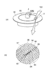
図14は、本発明の実施形態に係る磁気記録装置の磁気記録媒体の構成を例示する模式的斜視図である。
図14に表したように、本発明の実施形態に係る磁気記録装置に用いられる磁気記録媒体80は、非磁性体(あるいは空気)87により互いに分離された垂直配向した多粒子系の磁性ディスクリートトラック(記録トラック)86を有する。この磁気記録媒体80がスピンドルモータ4により回転され、媒体移動方向85に向けて移動する際に、上記の実施形態に係る磁気記録ヘッドのいずれかが設けられ、これにより、記録磁化84を形成することができる。
このように、本発明の実施形態に係る磁気記録装置においては、磁気記録媒体80は、隣接し合う記録トラック同士が非磁性部材を介して形成されたディスクリートトラック媒体とすることができる。
Hereinafter, a magnetic recording medium that can be used in the magnetic recording apparatus of the above embodiment will be described.
FIG. 14 is a schematic perspective view illustrating the configuration of the magnetic recording medium of the magnetic recording apparatus according to the embodiment of the invention.
As shown in FIG. 14, the
As described above, in the magnetic recording apparatus according to the embodiment of the present invention, the
スピントルク発振子10の記録トラック幅方向の幅(TS)を記録トラック86の幅(TW)以上で、かつ記録トラックピッチ(TP)以下とすることによって、スピントルク発振子10から発生する漏れ高周波磁界による隣接記録トラックの保磁力低下を大幅に抑制することができる。このため、本具体例の磁気記録媒体80では、記録したい記録トラック86のみを効果的に高周波磁界アシスト記録することができる。
Leakage high frequency generated from the
本具体例によれば、いわゆる「べた膜状」の多粒子系垂直媒体を用いるよりも、狭トラックすなわち高トラック密度の高周波アシスト記録装置を実現することが容易になる。また、高周波磁界アシスト記録方式を利用し、さらに従来の磁気記録ヘッドでは書き込み不可能なFePtやSmCo等の高磁気異方性エネルギー(Ku)の媒体磁性材料を用いることによって、媒体磁性粒子をナノメートルのサイズまでさらに微細化することが可能となり、記録トラック方向(ビット方向)においても、従来よりも遥かに線記録密度の高い磁気記録装置を実現することができる。
本実施形態に係る磁気記録装置によれば、ディスクリート型の磁気記録媒体80において、高い保磁力を有する磁気記録層に対しても確実に記録することができ、高密度かつ高速の磁気記録が可能となる。
According to this example, it is easier to realize a high-frequency assist recording apparatus having a narrow track, that is, a high track density, than using a so-called “solid film-like” multi-particle perpendicular medium. Further, by using a high-frequency magnetic field assisted recording method and using a medium magnetic material with high magnetic anisotropy energy (Ku) such as FePt or SmCo which cannot be written by a conventional magnetic recording head, the medium magnetic particles are nano-sized. It is possible to further reduce the size to a meter size, and it is possible to realize a magnetic recording device having a much higher linear recording density than the conventional one in the recording track direction (bit direction).
According to the magnetic recording apparatus of this embodiment, in the discrete
図15は、本発明の実施形態に係る磁気記録装置の別の磁気記録媒体の構成を例示する模式的斜視図である。
図15に表したように、本発明の実施形態に係る磁気記録装置に用いることができる別の磁気記録媒体80は、非磁性体87により互いに分離された磁性ディスクリートビット88を有する。この磁気記録媒体80がスピンドルモータ4により回転され、媒体移動方向85に向けて移動する際に、本発明の実施形態に係る磁気記録ヘッドにより、記録磁化84を形成することができる。
このように、本発明の実施形態に係る磁気記録装置においては、磁気記録媒体80は、非磁性部材を介して孤立した記録磁性ドットが規則的に配列形成されたディスクリートビット媒体とすることができる。
FIG. 15 is a schematic perspective view illustrating the configuration of another magnetic recording medium of the magnetic recording apparatus according to the embodiment of the invention.
As shown in FIG. 15, another
As described above, in the magnetic recording apparatus according to the embodiment of the present invention, the
本実施形態に係る磁気記録装置によれば、ディスクリート型の磁気記録媒体80において、高い保磁力を有する磁気記録層に対しても確実に記録することができ、高密度かつ高速の磁気記録が可能となる。
According to the magnetic recording apparatus of this embodiment, in the discrete
この具体例においても、スピントルク発振子10の記録トラック幅方向の幅(TS)を記録トラック86の幅(TW)以上で、かつ記録トラックピッチ(TP)以下とすることによって、スピントルク発振子10から発生する漏れ高周波磁界による隣接記録トラックの保磁力低下を大幅に抑制することができるため、記録したい記録トラック86のみを効果的に高周波磁界アシスト記録することができる。本具体例を用いれば、使用環境下での熱揺らぎ耐性を維持できる限りは、磁性ディスクリートビット88の高磁気異方性エネルギー(Ku)化と微細化を進めることで、10Tbits/inch2以上の高い記録密度の高周波磁界アシスト記録装置を実現できる可能性がある。
Also in this specific example, by setting the width (TS) of the
以上、具体例を参照しつつ、本発明の実施の形態について説明した。しかし、本発明は、これらの具体例に限定されるものではない。例えば、スピントルク発振子、磁気記録ヘッド、磁気ヘッドアセンブリ及び磁気記録装置を構成する各要素の具体的な構成に関しては、当業者が公知の範囲から適宜選択することにより本発明を同様に実施し、同様の効果を得ることができる限り、本発明の範囲に包含される。
また、各具体例のいずれか2つ以上の要素を技術的に可能な範囲で組み合わせたものも、本発明の要旨を包含する限り本発明の範囲に含まれる。
The embodiments of the present invention have been described above with reference to specific examples. However, the present invention is not limited to these specific examples. For example, regarding the specific configuration of each element constituting the spin torque oscillator, the magnetic recording head, the magnetic head assembly, and the magnetic recording apparatus, those skilled in the art can similarly implement the present invention by appropriately selecting from a known range. As long as the same effect can be obtained, it is included in the scope of the present invention.
Moreover, what combined any two or more elements of each specific example in the technically possible range is also included in the scope of the present invention as long as the gist of the present invention is included.
その他、本発明の実施の形態として上述したスピントルク発振子、磁気記録ヘッド、磁気ヘッドアセンブリ及び磁気記録装置を基にして、当業者が適宜設計変更して実施し得る全てのスピントルク発振子、磁気記録ヘッド、磁気ヘッドアセンブリ及び磁気記録装置も、本発明の要旨を包含する限り、本発明の範囲に属する。 In addition, based on the spin torque oscillator, the magnetic recording head, the magnetic head assembly, and the magnetic recording apparatus described above as embodiments of the present invention, all spin torque oscillators that can be implemented by a person skilled in the art with appropriate design changes, A magnetic recording head, a magnetic head assembly, and a magnetic recording apparatus also belong to the scope of the present invention as long as they include the gist of the present invention.
その他、本発明の思想の範疇において、当業者であれば、各種の変更例及び修正例に想到し得るものであり、それら変更例及び修正例についても本発明の範囲に属するものと了解される。 In addition, in the category of the idea of the present invention, those skilled in the art can conceive of various changes and modifications, and it is understood that these changes and modifications also belong to the scope of the present invention. .
3 ヘッドスライダー
3A 空気流入側
3B 空気流出側
4 スピンドルモータ
5 磁気記録ヘッド、
10、10b、10c スピントルク発振子
10a 発振層
20 バイアス層
22 中間層
25 積層構造体
30 スピン注入層
41 第1電極
42 第2電極
51 磁気記録ヘッド
60 書き込みヘッド部
61 主磁極
61s 媒体対向面
62 シールド(リターンパス)
70 再生ヘッド部
71 磁気再生素子
72a、72b 磁気シールド層
80 磁気記録媒体
81 磁気記録層
82 媒体基板
83 磁化
84 記録磁化
85 媒体移動方向
86 記録トラック
87 非磁性体
88 磁気ディスクリートビット
150 磁気記録装置
154 サスペンション
155 アクチュエータアーム
156 ボイスコイルモータ
157 軸受部
158 ヘッドジンバルアセンブリ(磁気ヘッドアセンブリ)
160 ヘッドスタックアセンブリ
161 支持フレーム
162 コイル
180 記録用媒体ディスク
190 信号処理部
3
10, 10b, 10c
DESCRIPTION OF
160
Claims (15)
垂直磁化膜を含む第2の磁性体層と、
前記第1の磁性体層と前記第2の磁性体層との間に設けられた中間層と、
を備え、
前記第2の磁性体層は、前記中間層との界面において、Fe−CoにAl、Si、Ge、Mn、Cr、Bの少なくともいずれか1つ以上を添加した材料からなる合金を含むことを特徴とするスピントルク発振子。 A first magnetic layer made of a material obtained by adding at least one of Al, Si, Ge, Mn, Cr, and B to Fe-Co, and containing an alloy having a Fe composition ratio of 20 atomic percent or more and a bcc structure When,
A second magnetic layer including a perpendicular magnetization film;
An intermediate layer provided between the first magnetic layer and the second magnetic layer;
Equipped with a,
The second magnetic layer includes an alloy made of a material obtained by adding at least one of Al, Si, Ge, Mn, Cr, and B to Fe-Co at the interface with the intermediate layer. A featured spin torque oscillator.
前記中間層との界面に設けられる前記合金は、前記垂直磁化膜と前記中間層との間に配置されることを特徴とする請求項1記載のスピントルク発振子。 The second magnetic layer further includes a perpendicular magnetization film,
Wherein said alloy is provided in the interface with the intermediate layer, the spin torque oscillator according to claim 1, characterized in that it is arranged between the perpendicular magnetization film and the intermediate layer.
垂直磁化膜を含む第2の磁性体層と、
前記第1の磁性体層と前記第2の磁性体層との間に設けられた中間層と、
を備え、
前記第2の磁性体層は、前記中間層との界面において、Fe−CoにAl、Si、Ge、Mn、Cr、Bの少なくともいずれか1つ以上を添加した材料からなる合金を含むことを特徴とするスピントルク発振子。 A first magnetic layer;
A second magnetic layer including a perpendicular magnetization film;
An intermediate layer provided between the first magnetic layer and the second magnetic layer;
With
The second magnetic layer includes an alloy made of a material obtained by adding at least one of Al, Si, Ge, Mn, Cr, and B to Fe-Co at the interface with the intermediate layer. A featured spin torque oscillator.
前記中間層との界面に設けられる前記合金は、前記垂直磁化膜と前記中間層との間に配置されることを特徴とする請求項4記載のスピントルク発振子。 The second magnetic layer further includes a perpendicular magnetization film,
5. The spin torque oscillator according to claim 4 , wherein the alloy provided at the interface with the intermediate layer is disposed between the perpendicular magnetization film and the intermediate layer.
前記スピントルク発振子に併置された主磁極と、
を備えたことを特徴とする磁気記録ヘッド。 The spin torque oscillator according to any one of claims 1 to 5 ,
A main magnetic pole juxtaposed to the spin torque oscillator;
A magnetic recording head comprising:
前記磁気記録ヘッドが搭載されたヘッドスライダーと、
前記ヘッドスライダーを一端に搭載するサスペンションと、
前記サスペンションの他端に接続されたアクチュエータアームと、
を備えたことを特徴とする磁気ヘッドアセンブリ。 A magnetic recording head according to any one of claims 6 to 9 ,
A head slider on which the magnetic recording head is mounted;
A suspension for mounting the head slider at one end;
An actuator arm connected to the other end of the suspension;
A magnetic head assembly comprising:
請求項10記載の磁気ヘッドアセンブリと、
前記磁気ヘッドアセンブリに搭載された前記磁気記録ヘッドを用いて前記磁気記録媒体への信号の書き込みと読み出しを行う信号処理部と、
を備えたことを特徴とする磁気記録装置。 A magnetic recording medium;
A magnetic head assembly according to claim 10 ;
A signal processing unit that writes and reads signals to and from the magnetic recording medium using the magnetic recording head mounted on the magnetic head assembly;
A magnetic recording apparatus comprising:
Priority Applications (2)
| Application Number | Priority Date | Filing Date | Title |
|---|---|---|---|
| JP2008161025A JP5361259B2 (en) | 2008-06-19 | 2008-06-19 | Spin torque oscillator, magnetic recording head, magnetic head assembly, and magnetic recording apparatus |
| US12/382,940 US8687321B2 (en) | 2008-06-19 | 2009-03-26 | Magnetic head assembly |
Applications Claiming Priority (1)
| Application Number | Priority Date | Filing Date | Title |
|---|---|---|---|
| JP2008161025A JP5361259B2 (en) | 2008-06-19 | 2008-06-19 | Spin torque oscillator, magnetic recording head, magnetic head assembly, and magnetic recording apparatus |
Related Child Applications (1)
| Application Number | Title | Priority Date | Filing Date |
|---|---|---|---|
| JP2013150389A Division JP2013251042A (en) | 2013-07-19 | 2013-07-19 | Spin torque oscillator, magnetic recording head, magnetic head assembly, and magnetic recorder |
Publications (3)
| Publication Number | Publication Date |
|---|---|
| JP2010003354A JP2010003354A (en) | 2010-01-07 |
| JP2010003354A5 JP2010003354A5 (en) | 2012-02-16 |
| JP5361259B2 true JP5361259B2 (en) | 2013-12-04 |
Family
ID=41431015
Family Applications (1)
| Application Number | Title | Priority Date | Filing Date |
|---|---|---|---|
| JP2008161025A Expired - Fee Related JP5361259B2 (en) | 2008-06-19 | 2008-06-19 | Spin torque oscillator, magnetic recording head, magnetic head assembly, and magnetic recording apparatus |
Country Status (2)
| Country | Link |
|---|---|
| US (1) | US8687321B2 (en) |
| JP (1) | JP5361259B2 (en) |
Families Citing this family (32)
| Publication number | Priority date | Publication date | Assignee | Title |
|---|---|---|---|---|
| JP2008277586A (en) | 2007-04-27 | 2008-11-13 | Toshiba Corp | Magnetic element, magnetic recording head and magnetic recording apparatus |
| US8994587B2 (en) | 2010-05-14 | 2015-03-31 | Qualcomm Incorporated | Compressed sensing for navigation data |
| JP4358279B2 (en) | 2007-08-22 | 2009-11-04 | 株式会社東芝 | Magnetic recording head and magnetic recording apparatus |
| JP4929108B2 (en) * | 2007-09-25 | 2012-05-09 | 株式会社東芝 | Magnetic head and magnetic recording apparatus |
| JP2009080875A (en) | 2007-09-25 | 2009-04-16 | Toshiba Corp | Magnetic head and magnetic recording system |
| JP5377893B2 (en) | 2008-06-19 | 2013-12-25 | 株式会社東芝 | Magnetic head assembly and magnetic recording / reproducing apparatus |
| JP5361259B2 (en) | 2008-06-19 | 2013-12-04 | 株式会社東芝 | Spin torque oscillator, magnetic recording head, magnetic head assembly, and magnetic recording apparatus |
| JP2010040126A (en) | 2008-08-06 | 2010-02-18 | Toshiba Corp | Magnetic recording head, magnetic head assembly, and magnetic recording device |
| JP5173750B2 (en) | 2008-11-06 | 2013-04-03 | 株式会社東芝 | Spin torque oscillator, magnetic recording head, magnetic head assembly, and magnetic recording apparatus |
| JP5558698B2 (en) | 2008-11-28 | 2014-07-23 | 株式会社東芝 | Magnetic recording head, magnetic head assembly, magnetic recording apparatus, and magnetic recording method |
| US8705213B2 (en) * | 2010-02-26 | 2014-04-22 | Seagate Technology Llc | Magnetic field detecting device with shielding layer at least partially surrounding magnetoresistive stack |
| JP2011198399A (en) * | 2010-03-17 | 2011-10-06 | Toshiba Corp | Magnetic recording head, magnetic head assembly, and magnetic recording and reproducing apparatus |
| JP5581980B2 (en) * | 2010-11-08 | 2014-09-03 | 株式会社日立製作所 | Magnetic recording head and magnetic recording apparatus |
| JP2012119027A (en) * | 2010-11-30 | 2012-06-21 | Toshiba Corp | Magnetic recording head, magnetic head assembly, and magnetic recorder |
| JP2012226799A (en) * | 2011-04-18 | 2012-11-15 | Toshiba Corp | Magnetic recording head, head gimbal assembly equipped with the same, and disc device |
| US8456967B1 (en) | 2011-10-12 | 2013-06-04 | Western Digital (Fremont), Llc | Systems and methods for providing a pole pedestal for microwave assisted magnetic recording |
| US8982502B2 (en) * | 2011-12-12 | 2015-03-17 | HGST Netherlands B.V. | Hard disk drive with write assist based on detected conditions |
| JP5606482B2 (en) * | 2012-03-26 | 2014-10-15 | 株式会社東芝 | Magnetic head, magnetic head assembly, magnetic recording / reproducing apparatus, and magnetic head manufacturing method |
| JP5902037B2 (en) | 2012-05-25 | 2016-04-13 | 株式会社東芝 | Magnetic recording head, magnetic head assembly, and magnetic recording / reproducing apparatus |
| US8941196B2 (en) * | 2012-07-10 | 2015-01-27 | New York University | Precessional reversal in orthogonal spin transfer magnetic RAM devices |
| US8970996B2 (en) * | 2012-09-27 | 2015-03-03 | HSGT Netherlands B.V. | Spin-torque oscillator for microwave assisted magnetic recording |
| US8953283B2 (en) | 2012-11-29 | 2015-02-10 | Kabushiki Kaisha Toshiba | Magnetic head, magnetic head assembly, and magnetic recording/reproduction apparatus |
| US8908330B1 (en) | 2012-12-21 | 2014-12-09 | Western Digital Technologies, Inc. | Spin torque oscillator for microwave assisted magnetic recording with optimal geometries |
| US9355654B1 (en) | 2012-12-21 | 2016-05-31 | Western Digital Technologies, Inc. | Spin torque oscillator for microwave assisted magnetic recording with increased damping |
| JP6000866B2 (en) * | 2013-01-31 | 2016-10-05 | 株式会社日立製作所 | Magnetic head and magnetic recording / reproducing apparatus |
| JP2015043247A (en) * | 2013-08-26 | 2015-03-05 | 株式会社東芝 | Magnetic recording head and magnetic record reproducing apparatus using the same |
| JP2018147540A (en) | 2017-03-08 | 2018-09-20 | 株式会社東芝 | Magnetic head and magnetic recording/reproducing device |
| US11367551B2 (en) * | 2017-12-20 | 2022-06-21 | Montana State University | Large moments in BCC FExCOyMNz and other alloy thin films |
| JP7319604B2 (en) * | 2019-10-03 | 2023-08-02 | 株式会社東芝 | Magnetic head and magnetic recording device |
| JP7424946B2 (en) | 2019-11-07 | 2024-01-30 | 株式会社東芝 | Magnetic head and magnetic recording device |
| JP2022182326A (en) * | 2021-05-28 | 2022-12-08 | 株式会社東芝 | Magnetic head and magnetic recording device |
| JP2023020022A (en) * | 2021-07-30 | 2023-02-09 | 株式会社東芝 | Magnetic head and magnetic recording device |
Family Cites Families (133)
| Publication number | Priority date | Publication date | Assignee | Title |
|---|---|---|---|---|
| US3899834A (en) * | 1972-10-02 | 1975-08-19 | Westinghouse Electric Corp | Electronic compass system |
| US4103315A (en) | 1977-06-24 | 1978-07-25 | International Business Machines Corporation | Antiferromagnetic-ferromagnetic exchange bias films |
| US4782415A (en) * | 1985-10-02 | 1988-11-01 | International Business Machines Corp. | Differential twin track vertical read/write magnetic head structure |
| DE3728237A1 (en) | 1987-08-25 | 1989-03-09 | Philips Patentverwaltung | METHOD FOR WRITING BINARY INFORMATION IN A MAGNETO-OPTICAL STORAGE LAYER AND ARRANGEMENT FOR IMPLEMENTING THE METHOD |
| US5139322B1 (en) * | 1990-08-31 | 1996-06-18 | Zaca Inc | Medicine cabinet |
| JP3022023B2 (en) | 1992-04-13 | 2000-03-15 | 株式会社日立製作所 | Magnetic recording / reproducing device |
| JPH05314424A (en) * | 1992-05-11 | 1993-11-26 | Matsushita Electric Ind Co Ltd | Magnetic head |
| US5576915A (en) | 1993-03-15 | 1996-11-19 | Kabushiki Kaisha Toshiba | Magnetoresistive head with antiferromagnetic sublayers interposed between first and second spin-valve units to exchange bias inner magnetic films thereof |
| JPH0845029A (en) * | 1994-08-01 | 1996-02-16 | Alps Electric Co Ltd | Thin-film magnetic head |
| US5898546A (en) | 1994-09-08 | 1999-04-27 | Fujitsu Limited | Magnetoresistive head and magnetic recording apparatus |
| US6011664A (en) * | 1995-08-31 | 2000-01-04 | Carnegie Mellon University | Techniques for ultrahigh density writing with a probe on erasable magnetic media |
| US5695864A (en) | 1995-09-28 | 1997-12-09 | International Business Machines Corporation | Electronic device using magnetic components |
| KR100274522B1 (en) | 1996-03-14 | 2001-01-15 | 니시무로 타이죠 | Multi magnetic head and magnetic disk device having this |
| US5869963A (en) | 1996-09-12 | 1999-02-09 | Alps Electric Co., Ltd. | Magnetoresistive sensor and head |
| JPH10302211A (en) | 1997-01-14 | 1998-11-13 | Sony Corp | Magnetic head and manufacture thereof |
| JP3255872B2 (en) * | 1997-04-17 | 2002-02-12 | アルプス電気株式会社 | Spin valve type thin film element and method of manufacturing the same |
| US5748399A (en) | 1997-05-13 | 1998-05-05 | International Business Machines Corporation | Resettable symmetric spin valve |
| JPH11316919A (en) * | 1998-04-30 | 1999-11-16 | Hitachi Ltd | Spin tunnel magnetoresistive effect magnetic head |
| JP3400378B2 (en) | 1999-03-26 | 2003-04-28 | アルプス電気株式会社 | Rotating head assembly using thin film magnetic head |
| US7330833B1 (en) * | 2000-09-29 | 2008-02-12 | Printvision, Inc. | System and method for auctioning services over an information exchange network |
| JP2001118217A (en) * | 1999-10-14 | 2001-04-27 | Alps Electric Co Ltd | Spin valve type thin-film magnetic device, thin-film magnetic head, and manufacturing method of spin valve thin-film magnetic device |
| US6519119B1 (en) | 1999-11-03 | 2003-02-11 | Seagate Technology, Llc | Structure for current perrpendicular to plane giant magnetoresistive read heads |
| US6621664B1 (en) | 2000-02-28 | 2003-09-16 | Seagate Technology Llc | Perpendicular recording head having integrated read and write portions |
| JP4297585B2 (en) * | 2000-02-28 | 2009-07-15 | 株式会社日立グローバルストレージテクノロジーズ | Magnetic recording / reproducing device |
| US6583969B1 (en) | 2000-04-12 | 2003-06-24 | International Business Machines Corporation | Pinned layer structure having nickel iron film for reducing coercivity of a free layer structure in a spin valve sensor |
| JP2002032903A (en) | 2000-07-13 | 2002-01-31 | Alps Electric Co Ltd | Thin film magnetic head for perpendicular magnetic recording |
| JP3872259B2 (en) * | 2000-07-26 | 2007-01-24 | セイコーインスツル株式会社 | Method for adjusting driving current of magnetic sensor and electronic compass |
| JP2002100005A (en) | 2000-09-25 | 2002-04-05 | Toshiba Corp | Magnetic head |
| JP4365520B2 (en) | 2000-09-29 | 2009-11-18 | Tdk株式会社 | Magnetic recording medium and magnetic recording / reproducing system |
| US6580589B1 (en) | 2000-10-06 | 2003-06-17 | International Business Machines Corporation | Pinned layer structure for a spin valve sensor having cobalt iron (CoFe) and cobalt iron oxide (CoFeO) laminated layers |
| JP3833512B2 (en) | 2000-10-20 | 2006-10-11 | 株式会社東芝 | Magnetoresistive effect element |
| US6937446B2 (en) | 2000-10-20 | 2005-08-30 | Kabushiki Kaisha Toshiba | Magnetoresistance effect element, magnetic head and magnetic recording and/or reproducing system |
| US20020051330A1 (en) | 2000-11-01 | 2002-05-02 | Seagate Technology Llc | High resistance CPP transducer in a read/write head |
| US6922316B2 (en) | 2000-11-10 | 2005-07-26 | Tdk Corporation | Thin-film magnetic head and method of manufacturing same |
| JP3629431B2 (en) | 2001-01-15 | 2005-03-16 | アルプス電気株式会社 | Method for manufacturing soft magnetic film and method for manufacturing thin film magnetic head |
| US6809900B2 (en) | 2001-01-25 | 2004-10-26 | Seagate Technology Llc | Write head with magnetization controlled by spin-polarized electron current |
| JP3861197B2 (en) | 2001-03-22 | 2006-12-20 | 株式会社東芝 | Manufacturing method of recording medium |
| US6785092B2 (en) * | 2001-07-24 | 2004-08-31 | Seagate Technology Llc | White head for high anisotropy media |
| US7532434B1 (en) | 2001-09-06 | 2009-05-12 | Schreck Erhard T | Recessed write pole for perpendicular recording |
| JP2003152239A (en) | 2001-11-12 | 2003-05-23 | Fujitsu Ltd | Magnetoresistive effect element and read head and drive having the same |
| JP3680035B2 (en) | 2002-03-29 | 2005-08-10 | 株式会社東芝 | Magnetic recording apparatus and magnetic recording method |
| JP4027145B2 (en) | 2002-04-15 | 2007-12-26 | キヤノン株式会社 | Perpendicular magnetic recording medium, magnetic recording / reproducing apparatus, and information processing apparatus |
| US7119990B2 (en) | 2002-05-30 | 2006-10-10 | Komag, Inc. | Storage device including a center tapped write transducer |
| JP2004171733A (en) | 2002-11-06 | 2004-06-17 | Alps Electric Co Ltd | Magnetic head, magnetic tape device including the same and method for producing the magnetic head |
| JP3989368B2 (en) | 2002-12-12 | 2007-10-10 | 株式会社東芝 | Magnetic head and magnetic recording apparatus |
| EP2264725B1 (en) * | 2002-12-13 | 2016-11-23 | Japan Science and Technology Agency | Magnetic apparatus with magnetic thin film |
| JP4873338B2 (en) | 2002-12-13 | 2012-02-08 | 独立行政法人科学技術振興機構 | Spin injection device and magnetic apparatus using the same |
| JP2004221298A (en) | 2003-01-15 | 2004-08-05 | Alps Electric Co Ltd | Magnetic detection element |
| JP4317717B2 (en) | 2003-01-22 | 2009-08-19 | 株式会社日立グローバルストレージテクノロジーズ | Magnetic disk drive using thin film magnetic head for perpendicular recording |
| KR20040069062A (en) | 2003-01-28 | 2004-08-04 | 삼성전자주식회사 | Magnetic recording head |
| JP4116913B2 (en) | 2003-03-26 | 2008-07-09 | Tdk株式会社 | Perpendicular magnetic recording head and magnetic recording apparatus |
| JP3889374B2 (en) | 2003-04-10 | 2007-03-07 | アルプス電気株式会社 | Magnetic head device and magnetic disk device using the magnetic head device |
| JP2004335931A (en) | 2003-05-12 | 2004-11-25 | Alps Electric Co Ltd | Cpp-type giant magnetoresistance effect element |
| JP2005025831A (en) * | 2003-06-30 | 2005-01-27 | Toshiba Corp | High-frequency oscillator, magnetic information recording head, and magnetic storage device |
| US6836971B1 (en) * | 2003-07-30 | 2005-01-04 | Honeywell International Inc. | System for using a 2-axis magnetic sensor for a 3-axis compass solution |
| US6980469B2 (en) * | 2003-08-19 | 2005-12-27 | New York University | High speed low power magnetic devices based on current induced spin-momentum transfer |
| US7120988B2 (en) * | 2003-09-26 | 2006-10-17 | Hitachi Global Storage Technologies Netherlands B.V. | Method for forming a write head having air bearing surface (ABS) |
| JP2005108315A (en) | 2003-09-30 | 2005-04-21 | Toshiba Corp | Perpendicular magnetic recording type disk drive and magnetic head |
| US7177122B2 (en) * | 2003-10-27 | 2007-02-13 | Seagate Technology Llc | Biasing for tri-layer magnetoresistive sensors |
| US7492550B2 (en) * | 2003-11-18 | 2009-02-17 | Tandberg Storage Asa | Magnetic recording head and method for high coercivity media, employing concentrated stray magnetic fields |
| US7271981B2 (en) * | 2003-11-20 | 2007-09-18 | Seagate Technology Llc | Ultrafast pulse field source utilizing optically induced magnetic transformation |
| US20050110004A1 (en) * | 2003-11-24 | 2005-05-26 | International Business Machines Corporation | Magnetic tunnel junction with improved tunneling magneto-resistance |
| JP3874759B2 (en) * | 2004-03-03 | 2007-01-31 | 横河電機株式会社 | Gyro compass |
| US7256955B2 (en) | 2004-03-17 | 2007-08-14 | Seagate Technology Llc | High frequency assisted writing |
| US7471491B2 (en) | 2004-03-30 | 2008-12-30 | Kabushiki Kaisha Toshiba | Magnetic sensor having a frequency filter coupled to an output of a magnetoresistance element |
| JP4050245B2 (en) | 2004-03-30 | 2008-02-20 | 株式会社東芝 | Magnetic recording head and magnetic storage device |
| JP2005294376A (en) | 2004-03-31 | 2005-10-20 | Toshiba Corp | Magnetic recording element and magnetic memory |
| US7322095B2 (en) | 2004-04-21 | 2008-01-29 | Headway Technologies, Inc. | Process of manufacturing a four-sided shield structure for a perpendicular write head |
| US20060039089A1 (en) * | 2004-08-17 | 2006-02-23 | Kabushiki Kaisha Toshiba | Magnetic oscillator, magnetic head, and magnetic recording and reproducing apparatus |
| JP5032009B2 (en) | 2004-08-17 | 2012-09-26 | 株式会社東芝 | Magnetic sensor, magnetic head, and magnetic recording / reproducing apparatus |
| US7466525B2 (en) | 2004-09-03 | 2008-12-16 | Tdk Corporation | Magnetic sensing element including laminated film composed of half-metal and NiFe alloy as free layer |
| JP4770144B2 (en) * | 2004-09-10 | 2011-09-14 | ソニー株式会社 | Memory element |
| JP4160947B2 (en) | 2004-11-09 | 2008-10-08 | Tdk株式会社 | Magnetic head and magnetic recording apparatus |
| JP2006147023A (en) | 2004-11-18 | 2006-06-08 | Fujitsu Ltd | Thin film magnetic head and its manufacturing method |
| US7161753B2 (en) | 2005-01-28 | 2007-01-09 | Komag, Inc. | Modulation of sidewalls of servo sectors of a magnetic disk and the resultant disk |
| US7397633B2 (en) | 2005-03-01 | 2008-07-08 | Seagate Technology, Llc | Writer structure with assisted bias |
| JP4677589B2 (en) | 2005-03-18 | 2011-04-27 | 独立行政法人科学技術振興機構 | Transmission circuit integrated microwave generation element and microwave detection method, microwave detection circuit, microwave detection element, and transmission circuit integrated microwave detection element |
| US7100294B1 (en) * | 2005-03-24 | 2006-09-05 | Spectron Glass And Electronics, Inc | Method of sensing tilt, tilt sensor, and method of manufacturing same |
| JP4585353B2 (en) | 2005-03-31 | 2010-11-24 | 株式会社東芝 | Magnetic oscillation element, magnetic sensor, magnetic head, and magnetic reproducing apparatus |
| JP4098786B2 (en) | 2005-03-31 | 2008-06-11 | 株式会社東芝 | Magnetic sensor and magnetic recording / reproducing apparatus |
| JP4032062B2 (en) | 2005-07-15 | 2008-01-16 | アルプス電気株式会社 | Perpendicular magnetic recording head |
| KR100682949B1 (en) | 2005-07-27 | 2007-02-15 | 삼성전자주식회사 | Perpendicular magnetic recording head and perpendicular magnetic recording apparatus comprising gap shield |
| US7973349B2 (en) * | 2005-09-20 | 2011-07-05 | Grandis Inc. | Magnetic device having multilayered free ferromagnetic layer |
| JP2007116003A (en) | 2005-10-21 | 2007-05-10 | Toshiba Corp | Magnetoresistance effect element and magnetic head, and magnetic recording and reproducing device using the same |
| US7637024B2 (en) * | 2005-10-26 | 2009-12-29 | Honeywell International Inc. | Magnetic field sensing device for compassing and switching |
| JP4886268B2 (en) | 2005-10-28 | 2012-02-29 | 株式会社東芝 | High-frequency oscillation element, in-vehicle radar device using the same, inter-vehicle communication device, and inter-information terminal communication device |
| US7461933B2 (en) * | 2005-12-07 | 2008-12-09 | Xerox Corporation | Sheet heater assembly having air bearing platelets |
| US7486475B2 (en) * | 2005-12-14 | 2009-02-03 | International Business Machines Corporation | Magnetic data system having bias circuit with bias resistor |
| US7911882B2 (en) | 2005-12-16 | 2011-03-22 | Tdk Corporation | Thin-film magnetic head with near-field-light-generating layer |
| JP4193847B2 (en) | 2006-01-20 | 2008-12-10 | Tdk株式会社 | THIN FILM MAGNETIC HEAD HAVING NEAR FIELD LIGHT GENERATING LAYER AND THERMAL EXPANSION PROJECTING LAYER, HEAD GIMBAL ASSY |
| US7473478B2 (en) * | 2005-12-30 | 2009-01-06 | Tdk Corporation | Oscillator |
| US7732881B2 (en) * | 2006-11-01 | 2010-06-08 | Avalanche Technology, Inc. | Current-confined effect of magnetic nano-current-channel (NCC) for magnetic random access memory (MRAM) |
| JP2006209960A (en) | 2006-03-13 | 2006-08-10 | Toshiba Corp | Magnetic recording-and-reproducing device |
| JP2006209964A (en) | 2006-03-27 | 2006-08-10 | Hitachi Global Storage Technologies Netherlands Bv | Magnetic disk device |
| JP2007299880A (en) | 2006-04-28 | 2007-11-15 | Toshiba Corp | Magnetoresistance effect element and its manufacturing method |
| US7616412B2 (en) * | 2006-07-21 | 2009-11-10 | Carnegie Melon University | Perpendicular spin-torque-driven magnetic oscillator |
| JP4231068B2 (en) | 2006-08-14 | 2009-02-25 | 株式会社東芝 | Magnetic head and magnetic recording apparatus |
| JP2008109118A (en) * | 2006-09-29 | 2008-05-08 | Toshiba Corp | Magnetoresistance effect element and magnetic random access memory using it |
| US7848059B2 (en) * | 2006-09-29 | 2010-12-07 | Kabushiki Kaisha Toshiba | Magnetoresistive effect device and magnetic random access memory using the same |
| US20080112087A1 (en) * | 2006-11-14 | 2008-05-15 | Seagate Technology Llc | WAMR writer with an integrated spin momentum transfer driven oscillator for generating a microwave assist field |
| US20080117545A1 (en) | 2006-11-20 | 2008-05-22 | Seagate Technology Llc | Data storage system with field assist source |
| EP2089732A2 (en) * | 2006-11-27 | 2009-08-19 | Nxp B.V. | A magnetic field sensor circuit |
| US7724469B2 (en) | 2006-12-06 | 2010-05-25 | Seagate Technology Llc | High frequency field assisted write device |
| US7633699B2 (en) * | 2006-12-15 | 2009-12-15 | Seagate Technology Llc | CPP reader with phase detection of magnetic resonance for read-back |
| US7876531B2 (en) * | 2007-01-09 | 2011-01-25 | Seagate Technology Llc | Virtual front shield writer |
| KR100866956B1 (en) * | 2007-01-26 | 2008-11-05 | 삼성전자주식회사 | Perpendicular magnetic recording head |
| US20080218891A1 (en) | 2007-03-07 | 2008-09-11 | Seagate Technology Llc | Magnetic recording device with an integrated microelectronic device |
| JP2008277586A (en) * | 2007-04-27 | 2008-11-13 | Toshiba Corp | Magnetic element, magnetic recording head and magnetic recording apparatus |
| KR20080108016A (en) * | 2007-06-07 | 2008-12-11 | 가부시끼가이샤 도시바 | Magnetic recording head and magnetic recording device |
| JP4358279B2 (en) * | 2007-08-22 | 2009-11-04 | 株式会社東芝 | Magnetic recording head and magnetic recording apparatus |
| US8994587B2 (en) * | 2010-05-14 | 2015-03-31 | Qualcomm Incorporated | Compressed sensing for navigation data |
| JP4919901B2 (en) * | 2007-09-04 | 2012-04-18 | 株式会社東芝 | Magnetic recording head and magnetic recording apparatus |
| JP4818234B2 (en) * | 2007-09-05 | 2011-11-16 | 株式会社東芝 | Magnetic recording / reproducing device |
| JP2009064500A (en) | 2007-09-05 | 2009-03-26 | Toshiba Corp | Magnetic head and magnetic disk device |
| JP2009070439A (en) | 2007-09-11 | 2009-04-02 | Toshiba Corp | Magnetic recording head and magnetic recording device |
| JP2009080875A (en) * | 2007-09-25 | 2009-04-16 | Toshiba Corp | Magnetic head and magnetic recording system |
| JP2009080878A (en) * | 2007-09-25 | 2009-04-16 | Toshiba Corp | Magnetic recording head and magnetic recording device |
| JP4996406B2 (en) | 2007-09-25 | 2012-08-08 | 株式会社東芝 | Amplifier, radio transmitter and radio receiver |
| JP4929108B2 (en) * | 2007-09-25 | 2012-05-09 | 株式会社東芝 | Magnetic head and magnetic recording apparatus |
| JP2009080904A (en) * | 2007-09-26 | 2009-04-16 | Toshiba Corp | Magnetic recording device |
| US8049567B2 (en) | 2007-11-01 | 2011-11-01 | Johan Persson | Circuit for phase locked oscillators |
| US8057925B2 (en) | 2008-03-27 | 2011-11-15 | Magic Technologies, Inc. | Low switching current dual spin filter (DSF) element for STT-RAM and a method for making the same |
| US9449618B2 (en) | 2008-04-21 | 2016-09-20 | Seagate Technology Llc | Microwave assisted magnetic recording system |
| JP5377893B2 (en) * | 2008-06-19 | 2013-12-25 | 株式会社東芝 | Magnetic head assembly and magnetic recording / reproducing apparatus |
| JP5361259B2 (en) | 2008-06-19 | 2013-12-04 | 株式会社東芝 | Spin torque oscillator, magnetic recording head, magnetic head assembly, and magnetic recording apparatus |
| JP2010003353A (en) * | 2008-06-19 | 2010-01-07 | Toshiba Corp | Magnetic recording head, magnetic head assembly, and magnetic recorder |
| JP2010020857A (en) | 2008-07-11 | 2010-01-28 | Toshiba Corp | Magnetic recording head, magnetic head assembly and magnetic recording system |
| JP2010040060A (en) * | 2008-07-31 | 2010-02-18 | Toshiba Corp | Magnetic head for high-frequency field assist recording and magnetic recording apparatus using the same |
| JP2010040126A (en) * | 2008-08-06 | 2010-02-18 | Toshiba Corp | Magnetic recording head, magnetic head assembly, and magnetic recording device |
| JP5320009B2 (en) * | 2008-10-06 | 2013-10-23 | 株式会社東芝 | Spin torque oscillator, magnetic recording head, magnetic head assembly, and magnetic recording apparatus |
| JP5173750B2 (en) * | 2008-11-06 | 2013-04-03 | 株式会社東芝 | Spin torque oscillator, magnetic recording head, magnetic head assembly, and magnetic recording apparatus |
| JP5558698B2 (en) | 2008-11-28 | 2014-07-23 | 株式会社東芝 | Magnetic recording head, magnetic head assembly, magnetic recording apparatus, and magnetic recording method |
| US8446690B2 (en) * | 2009-08-17 | 2013-05-21 | HGST Netherlands B.V. | Perpendicular magnetic recording write head with spin torque oscillator for fast switching of write pole magnetization |
-
2008
- 2008-06-19 JP JP2008161025A patent/JP5361259B2/en not_active Expired - Fee Related
-
2009
- 2009-03-26 US US12/382,940 patent/US8687321B2/en active Active
Also Published As
| Publication number | Publication date |
|---|---|
| US8687321B2 (en) | 2014-04-01 |
| US20090316303A1 (en) | 2009-12-24 |
| JP2010003354A (en) | 2010-01-07 |
Similar Documents
| Publication | Publication Date | Title |
|---|---|---|
| JP5361259B2 (en) | Spin torque oscillator, magnetic recording head, magnetic head assembly, and magnetic recording apparatus | |
| JP5320009B2 (en) | Spin torque oscillator, magnetic recording head, magnetic head assembly, and magnetic recording apparatus | |
| JP2013251042A (en) | Spin torque oscillator, magnetic recording head, magnetic head assembly, and magnetic recorder | |
| JP5173750B2 (en) | Spin torque oscillator, magnetic recording head, magnetic head assembly, and magnetic recording apparatus | |
| JP4919901B2 (en) | Magnetic recording head and magnetic recording apparatus | |
| US8970996B2 (en) | Spin-torque oscillator for microwave assisted magnetic recording | |
| JP4358279B2 (en) | Magnetic recording head and magnetic recording apparatus | |
| US8446691B2 (en) | Magnetic recording device | |
| JP5377893B2 (en) | Magnetic head assembly and magnetic recording / reproducing apparatus | |
| JP5268289B2 (en) | Magnetic recording head and magnetic recording apparatus | |
| JP5787524B2 (en) | Recording head, magnetic head assembly, and magnetic recording apparatus | |
| JP4960319B2 (en) | Magnetic recording device | |
| US20100027158A1 (en) | Magnetic head for high-frequency field assist recording and magnetic recording apparatus using magnetic head for high-frequency field assist recording | |
| WO2011027396A1 (en) | Magnetic recording/reproducing device | |
| WO2010016296A1 (en) | Magnetic recording head, magnetic head assembly and magnetic recording device | |
| JP4975836B2 (en) | Magnetic recording head and magnetic recording / reproducing apparatus using the same | |
| IE20150401A1 (en) | Spin torque oscillator with low magnetic moment and high perpendicular magnetic anisotropy material | |
| JP2009080878A (en) | Magnetic recording head and magnetic recording device | |
| JP2008277586A (en) | Magnetic element, magnetic recording head and magnetic recording apparatus | |
| JP2010020857A (en) | Magnetic recording head, magnetic head assembly and magnetic recording system | |
| JP2011198399A (en) | Magnetic recording head, magnetic head assembly, and magnetic recording and reproducing apparatus | |
| JP5570745B2 (en) | Magnetic recording head, magnetic head assembly, and magnetic recording apparatus | |
| JP5011331B2 (en) | Magnetic recording device | |
| JP2014149911A (en) | Magnetic recording head, magnetic head assembly, and magnetic recording device |
Legal Events
| Date | Code | Title | Description |
|---|---|---|---|
| A621 | Written request for application examination |
Free format text: JAPANESE INTERMEDIATE CODE: A621 Effective date: 20110328 |
|
| A521 | Request for written amendment filed |
Free format text: JAPANESE INTERMEDIATE CODE: A523 Effective date: 20110614 |
|
| A521 | Request for written amendment filed |
Free format text: JAPANESE INTERMEDIATE CODE: A523 Effective date: 20111226 |
|
| A977 | Report on retrieval |
Free format text: JAPANESE INTERMEDIATE CODE: A971007 Effective date: 20120815 |
|
| A131 | Notification of reasons for refusal |
Free format text: JAPANESE INTERMEDIATE CODE: A131 Effective date: 20120919 |
|
| A521 | Request for written amendment filed |
Free format text: JAPANESE INTERMEDIATE CODE: A523 Effective date: 20121115 |
|
| A131 | Notification of reasons for refusal |
Free format text: JAPANESE INTERMEDIATE CODE: A131 Effective date: 20130604 |
|
| A521 | Request for written amendment filed |
Free format text: JAPANESE INTERMEDIATE CODE: A523 Effective date: 20130719 |
|
| TRDD | Decision of grant or rejection written | ||
| A01 | Written decision to grant a patent or to grant a registration (utility model) |
Free format text: JAPANESE INTERMEDIATE CODE: A01 Effective date: 20130806 |
|
| A61 | First payment of annual fees (during grant procedure) |
Free format text: JAPANESE INTERMEDIATE CODE: A61 Effective date: 20130903 |
|
| LAPS | Cancellation because of no payment of annual fees |