JP2006209964A - Magnetic disk device - Google Patents
Magnetic disk device Download PDFInfo
- Publication number
- JP2006209964A JP2006209964A JP2006085468A JP2006085468A JP2006209964A JP 2006209964 A JP2006209964 A JP 2006209964A JP 2006085468 A JP2006085468 A JP 2006085468A JP 2006085468 A JP2006085468 A JP 2006085468A JP 2006209964 A JP2006209964 A JP 2006209964A
- Authority
- JP
- Japan
- Prior art keywords
- magnetic
- slider
- terminal
- thin film
- magnetic pole
- Prior art date
- Legal status (The legal status is an assumption and is not a legal conclusion. Google has not performed a legal analysis and makes no representation as to the accuracy of the status listed.)
- Pending
Links
Images


Landscapes
- Magnetic Heads (AREA)
- Adjustment Of The Magnetic Head Position Track Following On Tapes (AREA)
Abstract
Description
本発明は、磁気ディスク装置の高記録密度化を実現するための磁気ディスク装置に係わり、特に磁気ディスクと磁気ヘッドの距離を調整する機能を持った浮上量調整スライダを備えた磁気ディスク装置に関する。 The present invention relates to a magnetic disk device for realizing high recording density of a magnetic disk device, and more particularly to a magnetic disk device including a flying height adjustment slider having a function of adjusting a distance between a magnetic disk and a magnetic head.
磁気ディスク装置は、回転する磁気ディスクと、記録再生素子を搭載しサスペンションを備える磁気ヘッド支持機構によって支持され、磁気ディスクの径方向に位置決めされる薄膜磁気ヘッドスライダ(以下「スライダ」と称す)を有し、スライダが相対的に磁気ディスク上を走行して磁気ディスク上に記録された磁気情報を読み書きする。前記スライダは空気潤滑軸受として空気のくさび膜効果によって浮上し、磁気ディスクとスライダが直接は固体接触しないようになっている。磁気ディスク装置の高記録密度化と、それによる装置の大容量化あるいは小型化を実現するためには、スライダと磁気ディスクの距離、すなわちスライダ浮上量を縮め、線記録密度を上げることが有効である。 A magnetic disk apparatus includes a rotating magnetic disk and a thin film magnetic head slider (hereinafter referred to as a “slider”) that is supported by a magnetic head support mechanism that includes a recording / reproducing element and includes a suspension and is positioned in the radial direction of the magnetic disk. The slider travels relatively on the magnetic disk and reads / writes magnetic information recorded on the magnetic disk. The slider floats as an air-lubricated bearing by the wedge film effect of air so that the magnetic disk and the slider are not in direct solid contact. In order to increase the recording density of a magnetic disk device and increase the capacity or size of the device, it is effective to increase the linear recording density by reducing the distance between the slider and the magnetic disk, that is, the slider flying height. is there.
従来からスライダ浮上量の設計においては、加工ばらつきや使用環境気圧差、使用環境温度差などによる浮上量低下を見込み、最悪条件でもスライダとディスクが接触しないように、浮上量マージンを設けてきた。ヘッド個体毎に、または使用環境に応じて浮上量を調整する機能を設けたスライダを実現すれば上記マージンを廃することができ、スライダとディスクの接触を防ぎつつ記録再生素子の浮上量を大幅に縮めることができる。例えば、薄膜抵抗体から成る加熱装置を記録素子と再生素子の近傍に設け、スライダの一部を必要に応じて加熱して熱膨張、突出させ、記録素子及び再生素子と磁気記録媒体との距離を調整するスライダ構造が提案されている(例えば、特許文献1(第3頁および図1)参照)。
Conventionally, in the design of the slider flying height, a flying height margin has been provided so that the slider and the disk do not come into contact with each other even in the worst conditions, with the expectation that the flying height will decrease due to processing variations, operating environment pressure differences, operating environment temperature differences, and the like. If a slider with a function to adjust the flying height according to the individual head or according to the usage environment is realized, the above margin can be eliminated, and the flying height of the recording / reproducing element is greatly increased while preventing contact between the slider and the disk. Can be shortened. For example, a heating device composed of a thin film resistor is provided in the vicinity of the recording element and the reproducing element, and a part of the slider is heated as necessary to thermally expand and protrude, and the distance between the recording element and the reproducing element and the magnetic recording medium There has been proposed a slider structure for adjusting (see, for example, Patent Document 1 (
一方、従来のスライダでは磁気再生素子を外部に電気的に接続するための再生用中継端子と磁気記録素子を外部に電気的に接続するための記録素子の端子がある。スライダの中には、再生素子の端子(2端子)と記録素子の端子(2端子)に加えて、製造プロセス中の研磨及び洗浄の工程において水溶液中での磁性膜の腐食を抑制するための磁極腐食防止用端子(1端子)を必要とするスライダがある。(例えば、特許文献2(第3頁および図1)参照)。磁極腐食防止用端子を必要とするスライダの端子数は全て合わせて5個となる。
On the other hand, the conventional slider has a reproducing relay terminal for electrically connecting the magnetic reproducing element to the outside and a recording element terminal for electrically connecting the magnetic recording element to the outside. In addition to the reproducing element terminal (two terminals) and the recording element terminal (two terminals), the slider is used to suppress corrosion of the magnetic film in an aqueous solution during the polishing and cleaning steps during the manufacturing process. There is a slider that requires a magnetic pole corrosion prevention terminal (one terminal). (For example, see Patent Document 2 (
しかしながら、浮上量調整のために通電加熱する加熱装置用の端子を新たに設置すると、実装が困難になるという課題がある。従来のスライダには、記録素子の端子、再生素子の端子と磁極腐食防止用端子を合わせて5個の端子がある。これに対し、浮上量調整のために加熱装置用マイクロ熱アクチュエータ用の端子を新設すると端子の数が7個になり端子の実装が困難である。さらに、本発明の熱式浮上量調整スライダが実用化される次世代のスライダは更に小型化されるため、7個の端子をスライダに実装するのはより困難となる。 However, if a new terminal for a heating device that is electrically heated to adjust the flying height is newly installed, there is a problem that mounting becomes difficult. A conventional slider has five terminals including a recording element terminal, a reproducing element terminal, and a magnetic pole corrosion prevention terminal. On the other hand, when a terminal for a micro thermal actuator for a heating device is newly provided for adjusting the flying height, the number of terminals becomes seven and it is difficult to mount the terminals. Furthermore, since the next-generation slider in which the thermal flying height adjustment slider of the present invention is put into practical use is further miniaturized, it becomes more difficult to mount seven terminals on the slider.
また、7個の端子を無理に実装しようとすると、磁極腐食防止用端子を実装するスペースは浮上面近くにしかそのスペースを取ることが出来ない。 Further, if the seven terminals are forcibly mounted, the space for mounting the magnetic pole corrosion prevention terminal can be taken only near the air bearing surface.
スライダの製造工程では、浮上面形状を形成する研磨加工とその加工残渣を取り除くための洗浄工程がある。その際、端子側に保護材を付けるが、研磨加工により削れてしまい、磁極腐食防止用端子が露出してしまうことがある。加工残渣を取り除くための洗浄の際に使用するブラシは帯電していることが良くあるため、ブラシと磁極腐食防止用端子が接触すると磁極腐食防止用端子が帯電してしまい、腐食が起こる危険性がある。 In the manufacturing process of the slider, there are a polishing process for forming the air bearing surface shape and a cleaning process for removing the processing residue. At that time, a protective material is attached to the terminal side, but it may be scraped off by polishing and the magnetic pole corrosion prevention terminal may be exposed. Since the brush used for cleaning to remove processing residues is often charged, the contact between the brush and the magnetic pole corrosion prevention terminal may cause the magnetic pole corrosion prevention terminal to be charged and the risk of corrosion. There is.
本発明の目的は、通電加熱する加熱装置を搭載した熱式浮上量調整スライダの端子数を減らし、従来サイズの薄膜磁気ヘッドだけでなく、次世代の小型サイズの薄膜磁気ヘッドにおいても端子の実装を可能とすることにある。 An object of the present invention is to reduce the number of terminals of a thermal flying height adjustment slider equipped with a heating device for energization heating, so that terminals can be mounted not only in conventional size thin film magnetic heads but also in next generation small size thin film magnetic heads. Is to make it possible.
上記目的を達成するために、本発明では、スライダ基板と、前記基板上に積層形成されたスライダ薄膜と、該スライダ基板と該スライダ薄膜の間に形成された通電部と、磁気記録素子と、磁気再生素子とを備え、磁気記録媒体面上に対向するように浮上させて用いられる薄膜磁気ヘッドスライダにおいて、磁気記録素子の端子と、磁気再生素子の端子と、通電部の端子は薄膜磁気ヘッドスライダの流出側端面に形成され、通電部の端子は、水溶液中における標準電極電位が前記磁気記録素子および前記磁気再生素子よりも高い導体から形成され、かつ、磁気記録素子の一部である下部磁極もしくは前記磁気再生素子の一部である磁気シールドと電気的に接続して形成されているようにした。 In order to achieve the above object, in the present invention, a slider substrate, a slider thin film formed on the substrate, a current-carrying portion formed between the slider substrate and the slider thin film, a magnetic recording element, A thin film magnetic head slider having a magnetic reproducing element and used to float on a surface of a magnetic recording medium, wherein the magnetic recording element terminal, the magnetic reproducing element terminal, and the current-carrying terminal are thin film magnetic heads A terminal formed on the outflow side end face of the slider, and a terminal of the energizing portion is formed of a conductor having a standard electrode potential higher than that of the magnetic recording element and the magnetic reproducing element in an aqueous solution, and is a part of the magnetic recording element It is formed to be electrically connected to a magnetic pole or a magnetic shield that is a part of the magnetic reproducing element.
さらに、前記通電部は、薄膜磁気ヘッドスライダ基板上に形成された下地絶縁膜と、該下地絶縁膜上に形成された磁気再生素子の下部磁気シールドとの間に形成されているようにした。 Further, the energization portion is formed between a base insulating film formed on the thin film magnetic head slider substrate and a lower magnetic shield of the magnetic reproducing element formed on the base insulating film.
また、前記磁気記録素子の下部磁極と導通接続している記録素子の端子は前記サスペンション配線に導通し、かつ、アースに接続して形成されているようにした。 The terminal of the recording element that is conductively connected to the lower magnetic pole of the magnetic recording element is formed to be conductive to the suspension wiring and connected to the ground.
本発明によれば、熱式浮上量調整スライダの加熱装置すなわち通電部の端子の一方を下部磁極もしくはシールドに電気的に接続して磁極の腐食防止用端子の役割を持たせることにより、端子数を7端子から6端子へと1つ減らす事が可能となる。これにより、従来のスライダだけでなく、次世代の小型化されたスライダにおいても端子の実装ができ、限られた面積で必要な全ての電気的接続が可能となる。また、磁極をアースすることにより、浮上中に静電気がスライダに溜まってスライダ/ディスク間の放電が起こるのを防ぎ、信頼性を高めるという効果も奏する。 According to the present invention, the number of terminals is increased by electrically connecting one of the terminals of the heating device for the thermal flying height adjustment slider, i.e., the current-carrying portion, to the lower magnetic pole or the shield to serve as a corrosion prevention terminal for the magnetic pole. Can be reduced by one from 7 terminals to 6 terminals. Thus, terminals can be mounted not only on the conventional slider but also on the next-generation miniaturized slider, and all necessary electrical connections can be made in a limited area. In addition, by grounding the magnetic pole, static electricity can be prevented from accumulating on the slider during levitation, and discharge between the slider / disk can be prevented and reliability can be improved.
本発明の実施形態に係わる薄膜磁気ヘッドスライダ、およびそのスライダを用いた薄膜磁気ヘッドの製造方法ならびにこ該スライダを用いた磁気ヘッド支持気候を有する磁気ディスク装置について、図面を用いて以下説明する。 A thin film magnetic head slider according to an embodiment of the present invention, a method of manufacturing a thin film magnetic head using the slider, and a magnetic disk device having a magnetic head support climate using the slider will be described below with reference to the drawings.
(装置全体)
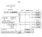
本発明の一実施例による磁気ディスク装置の概略構成を図1に示す。
(Whole device)
A schematic configuration of a magnetic disk apparatus according to an embodiment of the present invention is shown in FIG.
磁気ディスク装置は、磁気情報が格納されスピンドルモータによって回転する磁気ディスク10と、記録再生素子を搭載しサスペンションを有する磁気ヘッド支持機構(ロードビーム)15によって支持され、磁気ディスクの径方向に位置決めされたスライダ1を有し、スライダが相対的に磁気ディスク10上を走行して磁気ディスク上に記録された磁気情報を読み書きする。前記スライダは空気潤滑軸受として空気のくさび膜効果によって浮上し、磁気ディスクとスライダが直接は固体接触しないようになっている。回転する磁気ディスクと対面し、空気流を受けるスライダの後端がスライダの流出端面となる。
The magnetic disk device is supported by a
磁気ディスク装置の高記録密度化と、それによる装置の大容量化あるいは小型化を実現するためには、スライダ1と磁気ディスク10の距離、すなわちスライダ浮上量を縮め、線記録密度を上げることが有効である。近年、スライダ浮上量は10nm程度あるいは10nm以下まで縮められている。
In order to increase the recording density of the magnetic disk device and to increase the capacity or the size of the device, the distance between the slider 1 and the
スライダ1は、サスペンションを有する板ばね状の磁気ヘッド支持機構(ロードビーム)15に取り付けられており、磁気ヘッド支持機構(ロードビーム)によって磁気ディスク面への押し付け荷重を与えられ、磁気ヘッド支持機構(ロードビーム)15とともにボイスコイルモータ16によって磁気ディスク10の径方向にシーク動作し、磁気ディスク面全体で記録再生を行う。スライダ1は、装置の停止時あるいは読み書き命令が一定時間無い時に、磁気ディスク10上からランプ14上に待避する。
The slider 1 is attached to a leaf spring-like magnetic head support mechanism (load beam) 15 having a suspension, and a pressing load is applied to the magnetic disk surface by the magnetic head support mechanism (load beam). A
なお、ここではロード・アンロード機構を備えた装置を示したが、装置停止中はスライダ1が磁気ディスク10のある特定の領域で待機するコンタクト・スタート・ストップ方式の磁気ディスク装置でも本発明の効果は同様に得られる。
Here, an apparatus having a load / unload mechanism is shown, but a contact start / stop type magnetic disk apparatus in which the slider 1 stands by in a specific area of the
(スライダ)
図1におけるスライダのみを拡大して図2に示し、図2のコイル部分の拡大図を図12に示す。スライダ1は、アルミナとチタンカーバイドの焼結体(以後アルチックと略す)に代表される材料の基板(ウエハ)部分1aと、薄膜磁気ヘッド部分1bとから成る。薄膜磁気ヘッド部分1bは基板1a上に薄膜プロセスで形成された磁気記録素子(2の上段部)と磁気再生素子(2の下段部)、磁気記録素子および磁気再生素子と導通接触して形成された引きだし線となる内部の金属膜3c、磁気記録素子(2の上段部)を外部に電気的に接続するための記録素子の端子4、磁気再生素子(2の下段部)を外部に電気的に接続するための再生素子の端子5、スライダの一部を加熱して熱膨張、突出させ、記録再生素子の浮上量を調整するための加熱装置となる通電部11、加熱装置となる通電部11と導通接触して形成された引きだし線となる内部の金属膜17、加熱装置となる通電部11を外部に電気的に接続するための加熱装置となる通電部の端子30から成る。
(Slider)
Only the slider in FIG. 1 is enlarged and shown in FIG. 2, and an enlarged view of the coil portion in FIG. 2 is shown in FIG. The slider 1 comprises a substrate (wafer)
スライダ1は例えば従来のスライダでは、長さ1.25mm、幅1.0mm、厚さ0.3mmのほぼ直方体形状をしており、浮上面6、空気流入端面7、空気流出端面8、両側の側面、背面の計6面から構成される。なお、次世代の小型スライダでは質量減による位置決め精度の向上や低コスト化等のため、小型化の方向である。例えば規格では従来の約70パーセントの大きさになり、長さ0.85mm、0.7mm、厚さ0.23mmである。浮上面6にはイオンミリングやエッチングなどのプロセスによって微細な段差(ステップ軸受)が設けられており、図示されていないディスクと対向して空気圧力を発生し、背面に負荷される荷重を支える空気軸受の役目を果たしている。本発明のスライダは厚み0.1mmのスライダに対しても有効であることを確認した。スライダ厚み0.1mmは、後述のスライダとサスペンションの接着・配線における、サスペンションの端子とスライダの端子の形成において、一辺80μmの大きさの端子をスライダの流出端面に設けることを可能にするのに十分な厚さである。
For example, the conventional slider 1 has a substantially rectangular parallelepiped shape with a length of 1.25 mm, a width of 1.0 mm, and a thickness of 0.3 mm, and has a
浮上面6には前記のように段差が設けられ、実質的に平行な3種類の面に分類される。最もディスクに近いレール面6a、レール面より約100nm乃至200nm深いステップ軸受面である浅溝面6b、レール面より約1μm深くなっている深溝面6cの3種類である。ディスクが回転することで生じる空気流が、ステップ軸受である浅溝面6bからレール面である6aへ進入する際に、先すぼまりの流路によって圧縮され、正の空気圧力を生じる。一方、レール面6aや浅溝面6bから深溝面6cへ空気流が進入する際には流路の拡大によって、負の空気圧力が生じる。なお、図2は溝の深さを強調して示してある。
The air bearing
スライダ1は空気流入端7側の浮上量が空気流出端側8の浮上量より大きくなるような姿勢で浮上するように設計されている。従って流出端近傍の浮上面がディスクに最も接近する。流出端近傍では、レール面6aが周囲の浅溝面6b、深溝面6cに対して突出しているので、スライダピッチ姿勢およびロール姿勢が一定限度を超えて傾かない限り、レール面6aが最もディスクに近づくことになる。磁気記録再生素子2は、レール面6aの薄膜ヘッド部分1bに属する部分に形成されている。磁気ヘッド支持機構(ロードビーム)から押し付けられる荷重と、浮上面6で生じる正負の空気圧力とがうまくバランスし、磁気記録再生素子2からディスクまでの距離を10nm程度の適切な値に保つよう、浮上面6の形状が設計されている。
The slider 1 is designed to float in such a posture that the flying height on the air inflow end 7 side is larger than the flying height on the air
なお、ここでは浮上面6が実質的に平行な3種類の面6a、6b、6cから形成される、二段ステップ軸受浮上面のスライダについて説明したが、4種類以上の平行な面から形成されるステップ軸受浮上面のスライダでも本発明は同様の効果が得られる。
Here, the slider of the two-step step bearing air bearing surface in which the
(薄膜ヘッド構造)
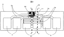
図2に示したスライダを空気流出端側から見た図を図3に示し、磁気記録素子2aと磁気再生素子2bが形成された薄膜ヘッド部分1bの断面拡大図として図3のX−X断面図を図4に示し、図3のY−Y断面図を図5に示す。また、図3のコイル部分の拡大図を図13に示した。図2、図3、図4、図5を用いて本実施例を詳細に説明する。
(Thin film head structure)
FIG. 3 is a view of the slider shown in FIG. 2 as viewed from the air outflow end side. FIG. 3 is an XX cross section of FIG. 3 as an enlarged cross-sectional view of the thin film head portion 1b on which the magnetic recording element 2a and the magnetic reproducing element 2b are formed. The figure is shown in FIG. 4, and the YY sectional view of FIG. 3 is shown in FIG. An enlarged view of the coil portion of FIG. 3 is shown in FIG. The present embodiment will be described in detail with reference to FIGS. 2, 3, 4, and 5.
本発明の磁気ヘッド製造方法における製造工程では、まず、基板1a上に下地絶縁膜9を形成し、次に下地絶縁膜9上にパーマロイからなる加熱装置11を形成し、アルミナ等からなる加熱体となる通電部11の絶縁層12を形成する。さらに、加熱体となる通電部から引き出された内部金属膜17を形成する。加熱体となる通電部については後で詳細に説明する。
In the manufacturing process of the magnetic head manufacturing method of the present invention, first, the base insulating film 9 is formed on the
次に、絶縁層12上に下部シールド膜18、アルミナ等から成る下部ギャップ膜19を形成し、さらに、磁気再生素子である磁気抵抗効果型素子(以下「MR素子」と称す)20と、MR素子20の磁気信号を引き出すための一対の電極21を形成する。次に、アルミナ等から成る上部ギャップ膜22、上部シールド膜23を形成し、さらに、アルミナ等から成る上部シールド絶縁膜24を形成する。次に、上部シールド絶縁膜24上に磁気記録用素子の下部磁極25を形成し、下部磁極25から引き出され、加熱装置から引き出された内部金属膜17の一方と下部磁極25を導通接続するための内部金属膜3cを形成する。次いで、アルミナ等から成る磁気ギャップ膜26、磁気記録用素子の上部磁極27を形成する。次に、上部磁極27に磁界を発生させるための電流を流すコイル28及び、有機絶縁膜29を形成する。さらに、MR素子20に接合した電極21から引き出された再生用引き出し線3bと、コイル28から引き出された記録用引き出し線3aを形成する。次に、以上の素子群を保護絶縁するためのアルミナ等からなる保護絶縁膜(スライダ薄膜ヘッド部分)1bを、成膜した素子全体を覆うように形成し、最後に、コイル27へ電流を外部より入力するための記録素子の端子4と、磁気信号を外部へ伝達するための再生素子の端子5を形成する。同時に、下部磁極25や上部磁極27の構成材料の一部である例えばCo・Ni・Fe合金よりも、後の工程である浮上面研磨及び洗浄で使用する水溶液中で標準電極電位が高い金属又はセラミックス、例えばAu、Ag、Pt、Ru、Rh、Pd、Os、Ir等の金属、又は、Al2O3・TiC、SiC、TiC、WC,B4C等の導電性のあるセラミックスからなる群から選ばれた材料(例えば、金属単体、合金又は、化合物)により通電部の端子を形成する。この通電部の端子は下部磁極25が内部金属膜2cを介して導通接触している加熱体である通電部から引き出された一対の内部金属膜17に導通接触したものであり、加熱体である通電部へ外部から電流を入力するものである。
Next, a
上記通電部の端子30の面積は、磁気記録素子の下部磁極25や上部磁極27の浮上面における断面積よりも大きく形成される。
The area of the terminal 30 of the energizing portion is formed larger than the cross-sectional area of the air bearing surface of the lower
上記のようにして、後工程において腐食を抑制したい下部磁極25と上部磁極27を下部磁極25や上部磁極27の構成材料の一部である例えばCo・Ni・Fe合金の単体における水溶液中での標準電極電位よりも高い電位である通電部端子30と導通接触させることによって、通電部端子30と導通後の下部磁極25と上部磁極27における水溶液中での標準電極電位を不働態領域に電位をずらすことで、下部磁極25と上部磁極27の腐食を抑制し、通電部端子30が磁極の腐食を防止する役割を果たせる。
As described above, the lower
続いて図6を用いて本発明の磁気ディスク装置の製造工程を説明する。上記のように、薄膜磁気ヘッド部分1bをスライダ基板1a上に複数個同時に形成した(工程101)後、基板1aを機械研削加工によりバー状態に切断する(工程102)。次に、切断したバー状態の切断面を研磨加工し浮上面6を形成した(工程103)後、洗浄を行う(工程104)。続いて、浮上面6にディスクとの短時間かつ軽微な接触が起こっても摩耗しないよう、また浮上面における薄膜素子部の腐食を防ぐため、厚さ数nmの炭素保護膜を形成する(工程105)。次に、スライダを安定にさせるための浮上面のレール面6a、浅溝面6b、深溝面6cを形成(工程106)後、バー状に切断された複数の薄膜磁気ヘッドを1個ずつに切断する(工程107)。再び洗浄を行い(工程108)、薄膜磁気ヘッドスライダ1を完成させる。その後、完成したスライダを磁気ヘッド支持機構の一部をなすサスペンションに接着し、配線組立てを行い(工程109)、洗浄を行う(工程110)。最後に磁気ディスク装置の組立てを行う(工程111)。工程110では、通電部の端子30は電気的に浮かせ、サスペンション下地のステンレスと電気的に絶縁させること、すなわち、導通させない配慮が好ましいことを確認した。理由は通電部の端子30すなわち磁極に通ずる配線がステンレスと導通すると異種金属同士が水溶液に接して閉回路を形成し、腐食が起こってしまう可能性があるからである。なお、上部シールド膜を下部磁極として兼ねるような薄膜磁気ヘッドにでは、上部シールド膜から内部金属膜2cを導通接触して形成することで同様の効果が得られる。
Next, the manufacturing process of the magnetic disk apparatus of the present invention will be described with reference to FIG. As described above, after a plurality of thin film magnetic head portions 1b are simultaneously formed on the
(加熱装置用中継端子を磁極腐食防止用端子と共有する理由)
通電部の端子は記録素子の端子や再生素子の端子と比べて、下部磁極に電気的に接続しても磁極に与える悪影響が少ない。その理由は、下部磁極に電気的に接続されている通電部の端子はアースに接続されているため下部磁極に電荷が加わる心配が無いことと、シールドと加熱体である通電部の絶縁膜は自由に厚くできるため通電部とシールド間での放電の心配が無く通電部と下部磁極を接続しても再生素子に与える悪影響は無いことが挙げられる。記録素子の端子や再生素子の端子に磁極の腐食防止の役割を持たせるために、下部磁極に接続すると、磁極や再生素子に電荷が加わる可能性があり、記録再生特性を悪化させてしまう危険性がある。そのため、磁極の腐食を防止する役割を持たせる中継端子は加熱装置用中継端子が最も適している。
(Reason for sharing relay terminal for heating device with terminal for preventing magnetic pole corrosion)
Compared with the recording element terminal and the reproducing element terminal, the current-carrying terminal has less adverse effect on the magnetic pole even if it is electrically connected to the lower magnetic pole. The reason is that the terminal of the current-carrying part that is electrically connected to the lower magnetic pole is connected to the ground, so there is no fear of charge being applied to the lower magnetic pole, and the insulation film of the current-carrying part that is the shield and heating element is Since the thickness can be freely increased, there is no fear of discharge between the current-carrying part and the shield, and there is no adverse effect on the reproducing element even if the current-carrying part and the lower magnetic pole are connected. If the terminal of the recording element or the terminal of the reproducing element has a role of preventing the corrosion of the magnetic pole, if it is connected to the lower magnetic pole, there is a possibility that electric charges may be applied to the magnetic pole or the reproducing element, which may deteriorate the recording / reproducing characteristics. There is sex. For this reason, the relay terminal for heating apparatus is most suitable as the relay terminal for preventing the magnetic pole from being corroded.
(加熱装置用端子の一方をアースする)
前述のように、下部磁極25と上部磁極27は、コイルを流れる電流で磁極間に磁界を発生して磁気情報を記録する記録素子であるため、磁極部分に加熱装置11へ入力する電流が加わることは避けなければならない。そのため、下部磁極25が内部金属膜2cと加熱装置から引き出された内部金属膜17を介して導通接続している片方の通電部の端子30はサスペンションの配線を介してアースに接続される必要がある。このようにして磁極の電位を強制的にゼロにすることにより、浮上中に静電気がスライダに溜まってスライダ/ディスク間の放電が起こるのを防ぎ、信頼性を高めるという効果がある。
(Ground one of the heating device terminals)
As described above, since the lower
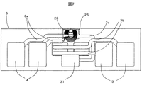
なお、本発明の別の実施形態として、浮上量調整用の加熱装置がなくても、単にヘッドの帯電およびディスクへの放電を防ぐための中継端子をスライダ上に設けた構成がある。この構成図を図7に示す。放電防止用中継端子31は下部磁極25に通じるとともに、サスペンション配線に金ボールやハンダ等で導通していて、稼動時には接地され磁極の電位をゼロに保つしくみである。
As another embodiment of the present invention, there is a configuration in which a relay terminal for simply preventing the head from being charged and discharging to the disk is provided on the slider without a flying height adjustment heating device. This configuration diagram is shown in FIG. The discharge preventing
(加熱体である通電部)
記録再生素子の近傍には、図4に示す如く、薄膜抵抗体による加熱である通電部11が薄膜プロセスを用いて形成されている。薄膜抵抗体である通電部として本実施例では、材質がパーマロイ、厚さが0.5μm、幅が4.5μmの細線を、奥行き60μm、幅60μmの領域に蛇行させ、間隙はアルミナで埋めて加熱体である通電部を形成した。抵抗値は約50Ωである。通電部置11を、流出端側から見た図(図4のZ−Z断面図)を図8に示す。
(Energizing part that is a heating element)
In the vicinity of the recording / reproducing element, as shown in FIG. 4, a current-carrying
(端子、配線の順番)
加熱体である通電部の端子は以下に述べる理由により、スライダの中央もしくは両端にあるのが望ましい。および記録再生素子用の合計6個の端子から、サスペンションジンバル上の配線パッドにボンディングされ、3本ずつの配線にわかれてジンバルの腕2本の上を通り、再び6本に合流し、サスペンションの根元まで配線が引き回される際に、スライダ中央の配線がサスペンション上で外側に来て、スライダ両端の配線がサスペンション上で中央に来る。現在4本配線のところに6本通そうとすると配線間隔を小さくせざるを得ないが、記録電流と再生電流の間を流れるとノイズの影響を受ける可能性がある。本発明では加熱体である通電部の端子の片方は下部磁極に導通接続しているため、通電部用配線は極力ノイズの影響を受け難くする必要がある。そのため、通電部の端子をスライダの中央にしてサスペンション上で一番外側に配線するか、スライダの両端にして、サスペンション上で一番中央に配線すれば、磁極がノイズの影響を受ける可能性を小さくすることができる
(浮上量調整方法)
次に、本発明の実施例による実際の浮上量調整方法を説明する。
(Terminal and wiring order)
It is desirable that the terminals of the current-carrying part, which is a heating element, be at the center or both ends of the slider for the reasons described below. In addition, a total of six terminals for recording / reproducing elements are bonded to wiring pads on the suspension gimbal, passed through two gimbals' arms, separated by three wirings, and merged again into six. When the wiring is routed to the base, the wiring at the center of the slider comes to the outside on the suspension, and the wiring at both ends of the slider comes to the center on the suspension. At present, when trying to pass 6 wires through 4 wires, the wiring interval must be reduced, but if it flows between the recording current and the reproducing current, it may be affected by noise. In the present invention, one of the terminals of the current-carrying part, which is a heating element, is conductively connected to the lower magnetic pole, so that the current-carrying part wiring needs to be made less susceptible to noise. For this reason, if the terminal of the current-carrying part is centered on the slider and wired on the outermost side on the suspension, or if both ends of the slider are wired on the centermost on the suspension, the magnetic pole may be affected by noise. Can be reduced (flying height adjustment method)
Next, an actual flying height adjustment method according to an embodiment of the present invention will be described.
浮上量調整手続きは、設計時、出荷前検査時、使用時の三段階に大きく分けられる。設計時は予想される最高の環境温度で、予想される最低の気圧で、連続ライトの時に、ばらつき下限のスライダのみがディスクと接触するよう設計する。すなわち、浮上量調整を伴わない従来のスライダ設計と同様である。携帯機器用の磁気ディスク装置では環境温度の高低差が激しく、サーバ用の磁気ディスク装置では連続ライト時の磁極の発熱で熱突出が起こって浮上量が低下するのが激しいなど、用いられる機器によって設計条件が異なる。 The flying height adjustment procedure is roughly divided into three stages: design, pre-shipment inspection, and use. At the time of design, the slider is designed so that only the slider with the lower limit of variation comes into contact with the disk during continuous writing at the highest expected ambient temperature and the lowest expected atmospheric pressure. That is, it is the same as the conventional slider design without the flying height adjustment. Depending on the equipment used, such as magnetic disk devices for portable devices, the difference in environmental temperature is severe, and in magnetic disk devices for servers, the amount of heat generated due to the heat generated by the magnetic poles during continuous writing is severe and the flying height decreases. The design conditions are different.
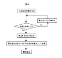
出荷前の検査時には、個々のスライダの浮上量を検査し、メモリに記憶する。浮上量の検査方法を具体的に図9に示す。浮上調整量は供給電力に比例するので、まず印加電力をゼロ状態にしておき、その後徐々に印加電力を増やしていって、スライダとディスクの接触を検知したら、その時の印加電力と、浮上調整量と供給電力の間の比例係数から、当該スライダの浮上量を計算するという方法である。スライダとディスクの接触を検知する方法については後述する。なお、スライダ浮上量の個別ばらつきだけでなく、内外周差も同時にメモリに記憶すると更に浮上量調整の精度を上げることができる。 At the time of inspection before shipment, the flying height of each slider is inspected and stored in the memory. A method for inspecting the flying height is specifically shown in FIG. Since the flying height adjustment is proportional to the supplied power, first set the applied power to zero, then gradually increase the applied power and detect contact between the slider and the disk. The flying height of the slider is calculated from a proportional coefficient between the power supply and the supplied power. A method for detecting contact between the slider and the disk will be described later. If not only the individual variations in the flying height of the slider but also the inner and outer circumference differences are simultaneously stored in the memory, the flying height adjustment accuracy can be further improved.
使用時は、基本的にはコンピュータなどのクライアント側からリードライト命令を受けた時、セレクトされたアクティブなヘッドのみに、当該スライダの浮上量に応じた電力を供給する。アイドル状態のヘッドには電力を供給しない。アクティブなヘッドに供給される電力量は、浮上調整量と供給電力の間の比例係数を用い、連続ライト時には減らし、高環境温度時には減らし、低環境温度時には増やす。 In use, basically, when a read / write command is received from the client side such as a computer, power corresponding to the flying height of the slider is supplied only to the selected active head. No power is supplied to the idle head. The amount of power supplied to the active head uses a proportional coefficient between the flying height adjustment amount and the supplied power, and is decreased during continuous writing, decreased at high environmental temperatures, and increased at low environmental temperatures.
(最も簡単な基本的調整アルゴリズム)
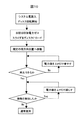
最も基本的な制御アルゴリズムを図10に示す。気圧や温度を測るセンサを別途設ける方法もあるが、気圧、温度、個体差など全ての影響が入った状態で、接触が起こる(近すぎる)ことなく、かつ磁気情報の再生にエラーが起こる(遠すぎる)こともない、という2つの条件が満足されれば問題ないため、接触や再生エラーを監視してそれらが起こった時だけ加熱装置への入力電力を調整するフィードバック制御をするのが最も簡単な制御方法である。なお、ロードによる衝撃で素子が傷つくのを防ぐため、スライダをディスクにロードする時、特に装置起動時は、加熱装置に通電せず浮上量を高くしておくのが有効である。接触の検知方法については後述する。
(Simplest basic adjustment algorithm)
The most basic control algorithm is shown in FIG. There is also a method of separately providing sensors for measuring atmospheric pressure and temperature, but in the state where all influences such as atmospheric pressure, temperature, individual differences are included, contact does not occur (too close) and an error occurs in reproduction of magnetic information ( If the two conditions are satisfied, it is best to monitor the contact and regeneration errors and perform feedback control to adjust the input power to the heating device only when they occur. It is a simple control method. In order to prevent the element from being damaged by the impact due to the load, it is effective to increase the flying height without energizing the heating device when the slider is loaded on the disk, particularly when the device is activated. A contact detection method will be described later.
なお、気圧差起因の浮上量変動およびヘッド個体差による浮上量変動を補償する方法については図示したように起動時のみでよいが、温度差起因の浮上量変動に関しては、規定の時間間隔毎に、あるいは使用中常に、接触および再生エラーを監視する必要がある。したがって、使用時の温度差変動が大きい機器に使用される磁気ディスク装置の場合は規定の時間間隔毎にあるいは使用中常に浮上量変動を補償すると有効である。 As shown in the figure, the method of compensating for the flying height fluctuation caused by the atmospheric pressure difference and the flying height fluctuation caused by the individual head difference is only required at the time of start-up. Or constantly during use, contact and regeneration errors need to be monitored. Therefore, in the case of a magnetic disk device used for a device having a large temperature difference fluctuation during use, it is effective to compensate for the flying height fluctuation at regular time intervals or during use.
環境温度情報は装置に付属の温度センサから得ることもでき、そうすればより精度の高い浮上量調整が可能である。 The environmental temperature information can also be obtained from a temperature sensor attached to the apparatus, so that the flying height can be adjusted with higher accuracy.
(接触検知方法)
接触を検知する方法は、(1)アコースティックエミッション(AE)センサを用いる方法、(2)接触発熱によって再生信号に表れるノイズであるサーマルアスペリティを監視する方法、(3)接触摩擦力によってスライダがピボット回りに微小回転しオフトラックが起こるオフトラック信号(ポジションエラーシグナル)を監視する方法、などがある。
(Contact detection method)
The method for detecting contact includes (1) a method using an acoustic emission (AE) sensor, (2) a method for monitoring thermal asperity, which is noise that appears in a reproduction signal due to contact heat generation, and (3) a slider pivoting by contact frictional force. For example, there is a method of monitoring an off-track signal (position error signal) in which an off-track occurs by slightly rotating around.
一方、磁気情報の再生エラーについてはいわゆるビットエラーレートを監視すればよい。再生エラーと違って記録エラーは監視するのが難しいが、記録時は記録素子のコイル発熱によって素子部が膨張して再生時より浮上量が低いのが一般的であるため、再生エラーが起こらない条件ならば記録エラーが起こる可能性も低い。 On the other hand, what is necessary is just to monitor what is called a bit error rate about the reproduction | regeneration error of magnetic information. Unlike playback errors, recording errors are difficult to monitor, but during recording, the element part expands due to coil heat generation of the recording element and the flying height is generally lower than during playback, so playback errors do not occur If the condition is met, the possibility of a recording error is low.
また、浮上量調整に関わる別の方法としては、再生信号の振幅を用いて再生素子と媒体間の距離をその場観測する方法があり、これを応用することもできる。 In addition, as another method for adjusting the flying height, there is a method of in-situ observation of the distance between the reproducing element and the medium using the amplitude of the reproducing signal, which can be applied.
(システム構成)
図11に、本発明による浮上量調整機能を備えた磁気ディスク装置の、システム構成を示す。なお、本図においては、加熱体である通電部を加熱装置として表示した。
(System configuration)
FIG. 11 shows a system configuration of a magnetic disk apparatus having a flying height adjustment function according to the present invention. In addition, in this figure, the electricity supply part which is a heating body was displayed as a heating apparatus.
1…スライダ、1a…スライダ基板部分、1b…スライダ薄膜ヘッド部分、2…記録再生素子、3…引き出し線、3a…記録用引き出し線、3b…再生用引き出し線、3c…内部金属膜、4…記録素子の端子、5…再生である端子、6…浮上面、6a…レール面、6b…浅溝面、6c…深溝面、7…空気流入端、8…空気流出端、9…下地絶縁膜、10…磁気ディスク、11…加熱体である通電部、12…絶縁層、13…磁気ディスク装置、14…ランプ、15…ロードビーム、16…ボイスコイルモータ、17…内部金属膜、18…下部シールド膜、19…下部ギャップ膜、20…磁気抵抗効果型素子、21…磁気信号を引き出すための電極、22…上部ギャップ膜、23…上部シールド膜、24…上部シールド絶縁膜、25…下部磁極、26…磁気ギャップ膜、27…上部磁極、28…コイル、29…有機絶縁膜、30…通電部の端子、31…放電防止用中継端子
DESCRIPTION OF SYMBOLS 1 ... Slider, 1a ... Slider board | substrate part, 1b ... Slider thin film head part, 2 ... Recording / reproducing element, 3 ... Lead-out line, 3a ... Lead-out line for recording, 3b ... Lead-out line for reproduction | regeneration, 3c ... Internal metal film, 4 ... Recording element terminal, 5... Reproduction terminal, 6. Air bearing surface, 6 a. Rail surface, 6 b. Shallow groove surface, 6 c. Deep groove surface, 7. Air inflow end, 8. DESCRIPTION OF
Claims (4)
4. A magnetic disk drive comprising the thin film magnetic head slider according to claim 1, wherein the slider has a thickness of 0.23 mm or less and 0.10 mm or more.
Priority Applications (1)
| Application Number | Priority Date | Filing Date | Title |
|---|---|---|---|
| JP2006085468A JP2006209964A (en) | 2006-03-27 | 2006-03-27 | Magnetic disk device |
Applications Claiming Priority (1)
| Application Number | Priority Date | Filing Date | Title |
|---|---|---|---|
| JP2006085468A JP2006209964A (en) | 2006-03-27 | 2006-03-27 | Magnetic disk device |
Related Parent Applications (1)
| Application Number | Title | Priority Date | Filing Date |
|---|---|---|---|
| JP2003369912A Division JP3978420B2 (en) | 2003-10-30 | 2003-10-30 | Magnetic head slider and method for manufacturing magnetic head support mechanism |
Publications (2)
| Publication Number | Publication Date |
|---|---|
| JP2006209964A true JP2006209964A (en) | 2006-08-10 |
| JP2006209964A5 JP2006209964A5 (en) | 2006-10-12 |
Family
ID=36966585
Family Applications (1)
| Application Number | Title | Priority Date | Filing Date |
|---|---|---|---|
| JP2006085468A Pending JP2006209964A (en) | 2006-03-27 | 2006-03-27 | Magnetic disk device |
Country Status (1)
| Country | Link |
|---|---|
| JP (1) | JP2006209964A (en) |
Cited By (13)
| Publication number | Priority date | Publication date | Assignee | Title |
|---|---|---|---|---|
| US8081397B2 (en) | 2008-06-19 | 2011-12-20 | Kabushiki Kaisha Toshiba | Magnetic head assembly and magnetic recording apparatus |
| US8139322B2 (en) | 2007-09-04 | 2012-03-20 | Kabushiki Kaisha Toshiba | Magnetic recording head with protruding spin torque oscillator |
| US8154825B2 (en) | 2007-09-25 | 2012-04-10 | Kabushiki Kaisha Toshiba | Magnetic recording head and magnetic recording device |
| US8164854B2 (en) | 2007-06-07 | 2012-04-24 | Kabushiki Kaisha Toshiba | Magnetic recording head with spin oscillation device and magnetic recording apparatus including the magnetic recording head |
| US8238060B2 (en) | 2007-08-22 | 2012-08-07 | Kabushiki Kaisha Toshiba | Magnetic recording head and magnetic recording apparatus |
| US8238058B2 (en) | 2008-08-06 | 2012-08-07 | Kabushiki Kaisha Toshiba | Magnetic recording head, magnetic head assembly, and magnetic recording apparatus |
| US8264799B2 (en) | 2007-04-27 | 2012-09-11 | Kabushiki Kaisha Toshiba | Magnetic recording head |
| US8295009B2 (en) | 2007-08-22 | 2012-10-23 | Kabushiki Kaisha Toshiba | Magnetic recording head and magnetic recording apparatus |
| US8320079B2 (en) | 2008-06-19 | 2012-11-27 | Kabushiki Kaisha Toshiba | Magnetic head assembly and magnetic recording/reproducing apparatus |
| US8325442B2 (en) | 2008-11-06 | 2012-12-04 | Kabushiki Kaisha Toshiba | Spin torque oscillator, magnetic recording head, magnetic head assembly and magnetic recording apparatus |
| US8687321B2 (en) | 2008-06-19 | 2014-04-01 | Kabushiki Kaisha Toshiba | Magnetic head assembly |
| US8767346B2 (en) | 2008-11-28 | 2014-07-01 | Kabushiki Kaisha Toshiba | Magnetic recording head, magnetic head assembly, magnetic recording apparatus, and magnetic recording method |
| US9196268B2 (en) | 2012-03-26 | 2015-11-24 | Kabushiki Kaisha Toshiba | Magnetic head manufacturing method forming sensor side wall film by over-etching magnetic shield |
Families Citing this family (1)
| Publication number | Priority date | Publication date | Assignee | Title |
|---|---|---|---|---|
| JP2009080875A (en) | 2007-09-25 | 2009-04-16 | Toshiba Corp | Magnetic head and magnetic recording system |
-
2006
- 2006-03-27 JP JP2006085468A patent/JP2006209964A/en active Pending
Cited By (16)
| Publication number | Priority date | Publication date | Assignee | Title |
|---|---|---|---|---|
| US8264799B2 (en) | 2007-04-27 | 2012-09-11 | Kabushiki Kaisha Toshiba | Magnetic recording head |
| US8164854B2 (en) | 2007-06-07 | 2012-04-24 | Kabushiki Kaisha Toshiba | Magnetic recording head with spin oscillation device and magnetic recording apparatus including the magnetic recording head |
| US8238060B2 (en) | 2007-08-22 | 2012-08-07 | Kabushiki Kaisha Toshiba | Magnetic recording head and magnetic recording apparatus |
| US8295009B2 (en) | 2007-08-22 | 2012-10-23 | Kabushiki Kaisha Toshiba | Magnetic recording head and magnetic recording apparatus |
| US8139322B2 (en) | 2007-09-04 | 2012-03-20 | Kabushiki Kaisha Toshiba | Magnetic recording head with protruding spin torque oscillator |
| US8154825B2 (en) | 2007-09-25 | 2012-04-10 | Kabushiki Kaisha Toshiba | Magnetic recording head and magnetic recording device |
| US8320079B2 (en) | 2008-06-19 | 2012-11-27 | Kabushiki Kaisha Toshiba | Magnetic head assembly and magnetic recording/reproducing apparatus |
| US8081397B2 (en) | 2008-06-19 | 2011-12-20 | Kabushiki Kaisha Toshiba | Magnetic head assembly and magnetic recording apparatus |
| US8687321B2 (en) | 2008-06-19 | 2014-04-01 | Kabushiki Kaisha Toshiba | Magnetic head assembly |
| US8238058B2 (en) | 2008-08-06 | 2012-08-07 | Kabushiki Kaisha Toshiba | Magnetic recording head, magnetic head assembly, and magnetic recording apparatus |
| US8325442B2 (en) | 2008-11-06 | 2012-12-04 | Kabushiki Kaisha Toshiba | Spin torque oscillator, magnetic recording head, magnetic head assembly and magnetic recording apparatus |
| US8767346B2 (en) | 2008-11-28 | 2014-07-01 | Kabushiki Kaisha Toshiba | Magnetic recording head, magnetic head assembly, magnetic recording apparatus, and magnetic recording method |
| US8995085B2 (en) | 2008-11-28 | 2015-03-31 | Kabushiki Kaisha Toshiba | Magnetic recording head, magnetic head assembly, magnetic recording apparatus, and magnetic recording method |
| US9129617B2 (en) | 2008-11-28 | 2015-09-08 | Kabushiki Kaisha Toshiba | Magnetic recording head, magnetic head assembly, magnetic recording apparatus, and magnetic recording method |
| US9378756B2 (en) | 2008-11-28 | 2016-06-28 | Kabushiki Kaisha Toshiba | Magnetic recording head, magnetic head assembly, magnetic recording apparatus, and magnetic recording method |
| US9196268B2 (en) | 2012-03-26 | 2015-11-24 | Kabushiki Kaisha Toshiba | Magnetic head manufacturing method forming sensor side wall film by over-etching magnetic shield |
Similar Documents
| Publication | Publication Date | Title |
|---|---|---|
| JP3978420B2 (en) | Magnetic head slider and method for manufacturing magnetic head support mechanism | |
| JP2006209964A (en) | Magnetic disk device | |
| JP4072469B2 (en) | Magnetic head slider and magnetic disk apparatus | |
| JP4979894B2 (en) | Magnetic disk unit | |
| JP5085853B2 (en) | Method for providing electrical crossing in a laminated structure | |
| US7583479B2 (en) | Thin-film magnetic head with heater in overcoat multilayer, head gimbal assembly with thin-film magnetic head, and magnetic disk drive apparatus with head gimbal assembly | |
| US7733606B2 (en) | Thin film magnetic head with thermal flying height control pads located at both ends of all pads series on slider side plane | |
| US20090262460A1 (en) | Head assembly having a sensing element | |
| JP2010027156A (en) | Magnetic recorder and contact detection method | |
| JP2007287277A (en) | Magnetic head slider and head gimbal assembly | |
| JP2010146629A (en) | Thin-film magnetic head including built-in thin-film acoustic-emission sensor | |
| JP2006053973A (en) | Magnetic head slider and magnetic disk device | |
| JP2007287190A (en) | Thin film magnetic head | |
| JP2007280502A (en) | Magnetic head slider | |
| US8503132B2 (en) | Head gimbal assembly, slider, and method of manufactuing a head gimbal assembly with reduced lead length | |
| JP2008165950A (en) | Magnetic head slider, head gimbal assembly, and magnetic disk device | |
| JP4704947B2 (en) | Thin film magnetic head | |
| US8144427B2 (en) | Magnetic head, head assembly and magnetic recording/reproducing apparatus | |
| US8213117B2 (en) | Magnetic head with protective layer and a protective film removal method for the magnetic head | |
| US20070217053A1 (en) | Storage device | |
| JP2008084466A (en) | Head slider support device and storage system | |
| JP2008186549A (en) | Magnetic head and disk drive equipped therewith | |
| US7777990B2 (en) | Magnetic disk unit and magnetic head slider | |
| US20100321816A1 (en) | Magnetic head and disk apparatus provided with the same | |
| JP2007265493A (en) | Method for manufacturing magnetic head slider, method for manufacturing head gimbals assembly, and the magnetic head slider |
Legal Events
| Date | Code | Title | Description |
|---|---|---|---|
| A521 | Written amendment |
Free format text: JAPANESE INTERMEDIATE CODE: A523 Effective date: 20060829 |
|
| A621 | Written request for application examination |
Free format text: JAPANESE INTERMEDIATE CODE: A621 Effective date: 20060829 |
|
| A131 | Notification of reasons for refusal |
Free format text: JAPANESE INTERMEDIATE CODE: A131 Effective date: 20070605 |
|
| A521 | Written amendment |
Free format text: JAPANESE INTERMEDIATE CODE: A523 Effective date: 20070831 |
|
| A131 | Notification of reasons for refusal |
Free format text: JAPANESE INTERMEDIATE CODE: A131 Effective date: 20071030 |
|
| A521 | Written amendment |
Effective date: 20080130 Free format text: JAPANESE INTERMEDIATE CODE: A523 |
|
| A02 | Decision of refusal |
Effective date: 20080513 Free format text: JAPANESE INTERMEDIATE CODE: A02 |