JP5377893B2 - Magnetic head assembly and magnetic recording / reproducing apparatus - Google Patents
Magnetic head assembly and magnetic recording / reproducing apparatus Download PDFInfo
- Publication number
- JP5377893B2 JP5377893B2 JP2008160856A JP2008160856A JP5377893B2 JP 5377893 B2 JP5377893 B2 JP 5377893B2 JP 2008160856 A JP2008160856 A JP 2008160856A JP 2008160856 A JP2008160856 A JP 2008160856A JP 5377893 B2 JP5377893 B2 JP 5377893B2
- Authority
- JP
- Japan
- Prior art keywords
- magnetic
- recording
- layer
- spin torque
- torque oscillator
- Prior art date
- Legal status (The legal status is an assumption and is not a legal conclusion. Google has not performed a legal analysis and makes no representation as to the accuracy of the status listed.)
- Expired - Fee Related
Links
Images


Classifications
-
- B—PERFORMING OPERATIONS; TRANSPORTING
- B82—NANOTECHNOLOGY
- B82Y—SPECIFIC USES OR APPLICATIONS OF NANOSTRUCTURES; MEASUREMENT OR ANALYSIS OF NANOSTRUCTURES; MANUFACTURE OR TREATMENT OF NANOSTRUCTURES
- B82Y10/00—Nanotechnology for information processing, storage or transmission, e.g. quantum computing or single electron logic
-
- G—PHYSICS
- G11—INFORMATION STORAGE
- G11B—INFORMATION STORAGE BASED ON RELATIVE MOVEMENT BETWEEN RECORD CARRIER AND TRANSDUCER
- G11B5/00—Recording by magnetisation or demagnetisation of a record carrier; Reproducing by magnetic means; Record carriers therefor
- G11B5/127—Structure or manufacture of heads, e.g. inductive
- G11B5/33—Structure or manufacture of flux-sensitive heads, i.e. for reproduction only; Combination of such heads with means for recording or erasing only
- G11B5/39—Structure or manufacture of flux-sensitive heads, i.e. for reproduction only; Combination of such heads with means for recording or erasing only using magneto-resistive devices or effects
- G11B5/3903—Structure or manufacture of flux-sensitive heads, i.e. for reproduction only; Combination of such heads with means for recording or erasing only using magneto-resistive devices or effects using magnetic thin film layers or their effects, the films being part of integrated structures
- G11B5/3906—Details related to the use of magnetic thin film layers or to their effects
-
- B—PERFORMING OPERATIONS; TRANSPORTING
- B82—NANOTECHNOLOGY
- B82Y—SPECIFIC USES OR APPLICATIONS OF NANOSTRUCTURES; MEASUREMENT OR ANALYSIS OF NANOSTRUCTURES; MANUFACTURE OR TREATMENT OF NANOSTRUCTURES
- B82Y25/00—Nanomagnetism, e.g. magnetoimpedance, anisotropic magnetoresistance, giant magnetoresistance or tunneling magnetoresistance
-
- G—PHYSICS
- G11—INFORMATION STORAGE
- G11B—INFORMATION STORAGE BASED ON RELATIVE MOVEMENT BETWEEN RECORD CARRIER AND TRANSDUCER
- G11B5/00—Recording by magnetisation or demagnetisation of a record carrier; Reproducing by magnetic means; Record carriers therefor
- G11B2005/0002—Special dispositions or recording techniques
- G11B2005/0005—Arrangements, methods or circuits
-
- G—PHYSICS
- G11—INFORMATION STORAGE
- G11B—INFORMATION STORAGE BASED ON RELATIVE MOVEMENT BETWEEN RECORD CARRIER AND TRANSDUCER
- G11B5/00—Recording by magnetisation or demagnetisation of a record carrier; Reproducing by magnetic means; Record carriers therefor
- G11B5/127—Structure or manufacture of heads, e.g. inductive
- G11B5/33—Structure or manufacture of flux-sensitive heads, i.e. for reproduction only; Combination of such heads with means for recording or erasing only
- G11B5/39—Structure or manufacture of flux-sensitive heads, i.e. for reproduction only; Combination of such heads with means for recording or erasing only using magneto-resistive devices or effects
- G11B2005/3996—Structure or manufacture of flux-sensitive heads, i.e. for reproduction only; Combination of such heads with means for recording or erasing only using magneto-resistive devices or effects large or giant magnetoresistive effects [GMR], e.g. as generated in spin-valve [SV] devices
Landscapes
- Engineering & Computer Science (AREA)
- Chemical & Material Sciences (AREA)
- Nanotechnology (AREA)
- Crystallography & Structural Chemistry (AREA)
- Manufacturing & Machinery (AREA)
- Physics & Mathematics (AREA)
- Mathematical Physics (AREA)
- Theoretical Computer Science (AREA)
- Magnetic Heads (AREA)
- Recording Or Reproducing By Magnetic Means (AREA)
Abstract
Description
本発明は、高記録密度、高記録容量、高データ転送レートのデータストレージの実現に好適なスピントルク発振子を備えた磁気記録ヘッド、磁気ヘッドアセンブリおよび磁気記録再生装置に関する。 The present invention relates to a magnetic recording head, a magnetic head assembly, and a magnetic recording / reproducing apparatus including a spin torque oscillator suitable for realizing data storage with high recording density, high recording capacity, and high data transfer rate.
1990年代においては、MR(Magneto-Resistive effect)ヘッドとGMR(Giant Magneto-Resistive effect)ヘッドの実用化が引き金となって、HDD(Hard Disk Drive)の記録密度と記録容量が飛躍的な増加を示した。しかし、2000年代に入ってから磁気記録媒体の熱揺らぎの問題が顕在化してきたために、記録密度増加のスピードが一時的に鈍化した。それでも、面内磁気記録よりも原理的に高密度記録に有利である垂直磁気記録が2005年に実用化されたことが牽引力となって、昨今、HDDの記録密度は年率約40%の伸びを示している。 In the 1990s, the practical use of MR (Magneto-Resistive effect) and GMR (Giant Magneto-Resistive effect) heads triggered a dramatic increase in HDD (Hard Disk Drive) recording density and recording capacity. Indicated. However, since the problem of thermal fluctuation of magnetic recording media has become apparent since the 2000s, the speed of increase in recording density has temporarily slowed down. Even so, perpendicular magnetic recording, which is in principle advantageous for high-density recording over in-plane magnetic recording, was put into practical use in 2005, and the recording density of HDDs has been growing at an annual rate of about 40%. Show.
また、最新の記録密度実証実験では250Gbits/inch2レベルが達成されており、このまま堅調に進展すれば、2012年頃には記録密度1Tbits/inch2が実現されると予想されている。しかしながら、このような高い記録密度の実現は、垂直磁気記録方式を用いても、再び熱揺らぎの問題が顕在化するために容易ではないと考えられる。 In the latest recording density verification experiment, the 250 Gbits / inch 2 level has been achieved, and if it progresses as it is, it is expected that a recording density of 1 Tbits / inch 2 will be realized around 2012. However, realization of such a high recording density is not easy even if the perpendicular magnetic recording method is used because the problem of thermal fluctuation becomes obvious again.
この問題を解消し得る記録方式として「高周波磁界アシスト記録方式」が提案されている。高周波磁界アシスト記録方式では、記録信号周波数より十分に高い、磁気記録媒体の共鳴周波数付近の高周波磁界を局所的に印加する。この結果、磁気記録媒体が共鳴し、高周波磁界を印加された磁気記録媒体の保磁力Hcを大幅に低減できる。このため、記録磁界に高周波磁界を重畳することにより、保磁力Hcがより高くかつ磁気異方性エネルギーKuがより高い磁気記録媒体への磁気記録が可能となる。 As a recording method that can solve this problem, a “high-frequency magnetic field assist recording method” has been proposed. In the high frequency magnetic field assisted recording method, a high frequency magnetic field that is sufficiently higher than the recording signal frequency and near the resonance frequency of the magnetic recording medium is locally applied. As a result, the magnetic recording medium resonates and the coercive force Hc of the magnetic recording medium to which a high frequency magnetic field is applied can be greatly reduced. Therefore, by superimposing a high-frequency magnetic field on the recording magnetic field, magnetic recording on a magnetic recording medium having a higher coercive force Hc and a higher magnetic anisotropy energy Ku becomes possible.
高周波磁界の発生手段として、スピントルク発振子を利用する手法が提案されている(例えば、特許文献1および2)。この特許文献1および2に開示された技術においては、スピントルク発振子は、スピン注入層と、非磁性層と、磁性層と、これらの層を挟む一対の電極層とを備えている。この一対の電極層を通じてスピントルク発振子に直流電流を通電すると、スピン注入層によって生じたスピントルクにより、磁性層の磁化が強磁性共鳴を起こす。その結果、スピントルク発振子から高周波磁界が発生することになる。 As a means for generating a high-frequency magnetic field, a method using a spin torque oscillator has been proposed (for example, Patent Documents 1 and 2). In the techniques disclosed in Patent Documents 1 and 2, the spin torque oscillator includes a spin injection layer, a nonmagnetic layer, a magnetic layer, and a pair of electrode layers sandwiching these layers. When a direct current is applied to the spin torque oscillator through the pair of electrode layers, the magnetization of the magnetic layer causes ferromagnetic resonance due to the spin torque generated by the spin injection layer. As a result, a high frequency magnetic field is generated from the spin torque oscillator.
スピントルク発振子のサイズは数十ナノメートル程度であるため、発生する高周波磁界はスピントルク発振子の近傍の数十ナノメートル程度に局在する。さらに高周波磁界の面内成分により、垂直磁化した磁気記録媒体を効率的に共鳴させることが可能となり、磁気記録媒体の保磁力を大幅に低下させることが可能となる。この結果、主磁極による記録磁界と、スピントルク発振子による高周波磁界とが重畳した部分のみで高密度磁気記録が行われ、高い保磁力Hcかつ高い磁気異方性エネルギーKuの磁気記録媒体を利用することが可能となり、これにより、高密度記録時の熱揺らぎの問題を回避することができる。
上述した構成では、スピントルク発振子と主磁極とを近接させた場合、書き込み時に主磁極からスピントルク発振子に大きな磁界が発生する。さらにこの主磁極からの書き込み磁界は、書き込み方向により正負に方向が反転する。その結果、主磁極からの書き込み磁界の変化により、スピントルク発振子の発振特性が大きく変化してしまい、安定な高周波磁界の発生が困難になる。 In the configuration described above, when the spin torque oscillator and the main magnetic pole are brought close to each other, a large magnetic field is generated from the main magnetic pole to the spin torque oscillator during writing. Further, the direction of the write magnetic field from the main magnetic pole is reversed between positive and negative depending on the write direction. As a result, the change in the write magnetic field from the main pole greatly changes the oscillation characteristics of the spin torque oscillator, making it difficult to generate a stable high-frequency magnetic field.
さらに、後述するように、主磁極からの磁界の影響によりスピントルク発振子の発振周波数と発振に必要な電流密度が増大し、スピントルク発振子の信頼性の確保が困難になるという問題が生じる。 Furthermore, as will be described later, the influence of the magnetic field from the main magnetic pole increases the oscillation frequency of the spin torque oscillator and the current density necessary for oscillation, which makes it difficult to ensure the reliability of the spin torque oscillator. .
本発明は、スピントルク発振子が受ける主磁極からの書き込み磁界を低減することのできる高周波磁界アシスト記録用の磁気記録ヘッドおよびこれを用いた磁気記録装置を提供することを目的とする。 An object of the present invention is to provide a magnetic recording head for high-frequency magnetic field assist recording and a magnetic recording apparatus using the same, which can reduce a write magnetic field from a main magnetic pole received by a spin torque oscillator.
本発明の第1の態様による磁気ヘッドアセンブリは、記録磁極と、第1および第2磁性層と、前記第1磁性層と前記第2磁性層との間に設けられる中間層とを有し、前記第1および第2磁性層間に電流を通電して前記第2磁性層から高周波磁界を発生するスピントルク発振子と、前記第2磁性層の側面の少なくとも一部に近接して配置される第3磁性層と、を備えていることを特徴とする。 The magnetic head assembly according to the first aspect of the present invention includes a recording magnetic pole, first and second magnetic layers, and an intermediate layer provided between the first magnetic layer and the second magnetic layer, A spin torque oscillator that generates a high-frequency magnetic field from the second magnetic layer by passing a current between the first and second magnetic layers, and a first portion disposed in proximity to at least a part of a side surface of the second magnetic layer. And 3 magnetic layers.
また、本発明の第2の態様による磁気ヘッドアセンブリは、記録磁極と、第1および第2磁性層と、前記第1磁性層と前記第2磁性層との間に設けられる中間層とを有し、前記第1および第2磁性層間に電流を通電して前記第2磁性層から高周波磁界を発生するスピントルク発振子と、前記記録磁極および前記第2磁性層のトラック幅方向の面に対向して設けられた磁気シールドと、を備え、前記磁気シールドと前記第2磁性層との間隔が、前記記録磁極と前記磁気シールドとの間隔よりも狭いことを特徴とする。 The magnetic head assembly according to the second aspect of the present invention includes a recording magnetic pole, first and second magnetic layers, and an intermediate layer provided between the first magnetic layer and the second magnetic layer. A spin torque oscillator that generates a high-frequency magnetic field from the second magnetic layer by passing a current between the first and second magnetic layers, and a surface in the track width direction of the recording magnetic pole and the second magnetic layer. And an interval between the magnetic shield and the second magnetic layer is narrower than an interval between the recording magnetic pole and the magnetic shield.
また、本発明の第3の態様による磁気記録再生装置は、磁気記録媒体と、第1または第2の態様のいずれかの磁気ヘッドアセンブリと、前記磁気記録媒体と前記磁気ヘッドアセンブリとが浮上または接触の状態で対峙しながら相対的に移動するように制御する移動制御部と、前記磁気ヘッドアセンブリを前記磁気記録媒体の所定記録位置に位置するように制御する位置制御部と、前記磁気ヘッドアセンブリを用いて前記磁気記録媒体への書き込み信号および前記磁気記録媒体からの読み出し信号を処理する信号処理手段と、を備えることを特徴とする。 According to a third aspect of the present invention, there is provided a magnetic recording / reproducing apparatus in which a magnetic recording medium, the magnetic head assembly according to the first or second aspect, the magnetic recording medium and the magnetic head assembly float or A movement control unit that controls to move relative to each other while facing each other; a position control unit that controls the magnetic head assembly to be positioned at a predetermined recording position of the magnetic recording medium; and the magnetic head assembly. And a signal processing means for processing a write signal to the magnetic recording medium and a read signal from the magnetic recording medium.
本発明によれば、発振層に加わる主磁極からの磁界を低減することができる。その結果、第1に、高周波磁界の発生に必要なスピントルク発振子に流す電流を低減することが可能となるので、電流による発熱を低減することができる。第2に、スピントルク発振子の発振特性の変動を低減することができる。 According to the present invention, the magnetic field from the main magnetic pole applied to the oscillation layer can be reduced. As a result, first, it is possible to reduce the current flowing through the spin torque oscillator necessary for generating the high-frequency magnetic field, so that heat generation due to the current can be reduced. Second, fluctuations in the oscillation characteristics of the spin torque oscillator can be reduced.
まず、本発明の実施形態を説明する前に、本発明に至った経緯について説明する。 First, before explaining the embodiments of the present invention, the background to the present invention will be described.
本発明者達は、主磁極からの書き込み磁界によるスピントルク発振子の発振特性の変動を低減するために、シミュレーションなどを用いて研究を行った。その結果、主磁極から発生される書き込み磁界に概ね比例して、スピントルク発振子の発振周波数と、発振に必要な電流密度とが増大してしまうことを本発明者達は見出した。さらに、従来の磁気ヘッド構造、例えば米国特許出願公開第2008/0019040号明細書に記載の磁気ヘッド構造では、通常10kOe以上の主磁極からの書き込み磁界がスピントルク発振子に加わること、その場合発振周波数は30GHz以上、電流密度は500MA/cm2になることが上記シミュレーションにより判明した。30GHz以上の高周波磁界を用いた書き込みは、磁気異方性エネルギーKuの高い磁気記録媒体にしか適用することができないという問題が生じる。また、500MA/cm2の電流密度をスピントルク発振子に投入すると発熱によりスピントルク発振子の信頼性の確保が困難になるという問題が生じる。 In order to reduce fluctuations in the oscillation characteristics of the spin torque oscillator due to the write magnetic field from the main magnetic pole, the present inventors conducted research using simulations and the like. As a result, the present inventors have found that the oscillation frequency of the spin torque oscillator and the current density necessary for oscillation increase in proportion to the write magnetic field generated from the main pole. Further, in a conventional magnetic head structure, for example, a magnetic head structure described in US Patent Application Publication No. 2008/0019040, a write magnetic field from a main magnetic pole of 10 kOe or more is normally applied to a spin torque oscillator, in which case oscillation occurs. The above simulation revealed that the frequency is 30 GHz or more and the current density is 500 MA / cm 2 . The writing using a high frequency magnetic field of 30 GHz or more has a problem that it can be applied only to a magnetic recording medium having a high magnetic anisotropy energy Ku. Further, when a current density of 500 MA / cm 2 is input to the spin torque oscillator, there is a problem that it becomes difficult to ensure the reliability of the spin torque oscillator due to heat generation.
そこで、本発明者達は鋭意研究に努めた結果、スピントルク発振子の側部に磁性体を設ければ、主磁極からの書き込み磁界によるスピントルク発振子の発振特性の変動を低減することができるとともに、スピントルク発振子が受ける主磁極からの書き込み磁界を低減することができることを発見した。これを以下に実施形態として説明する。 Thus, as a result of diligent research, the inventors of the present invention can reduce fluctuations in the oscillation characteristics of the spin torque oscillator due to the write magnetic field from the main pole if a magnetic material is provided on the side of the spin torque oscillator. It was found that the write magnetic field from the main pole received by the spin torque oscillator can be reduced. This will be described below as an embodiment.
(第1実施形態)
本発明の第1実施形態による高周波磁界アシスト記録用の磁気記録ヘッドを図1乃至図5を参照して説明する。図1は本実施形態の磁気記録ヘッド5の概略構成を示す斜視図、図2はこの磁気記録ヘッド5が搭載されるヘッドスライダー3を示す斜視図、図3はヘッドスライダー3が搭載されるヘッドスタックアセンブリ160を磁気記録媒体80側から見た斜視図である。また、図4は本実施形態の磁気記録ヘッド5に設けられるスピントルク発振子10と側壁磁性層101との配置を示す斜視図、図5は磁気記録ヘッド5を磁気記録媒体80から見た平面図である。
(First embodiment)
A magnetic recording head for high-frequency magnetic field assist recording according to a first embodiment of the present invention will be described with reference to FIGS. 1 is a perspective view showing a schematic configuration of a
本実施形態の磁気記録ヘッド5は、書き込みヘッド部60と、再生ヘッド部70と、を備えている。再生ヘッド部70は、磁気再生素子71と、この磁気再生素子を挟む磁気シールド層72a、72bと、を有する。磁気再生素子71としては、GMR素子またはTMR素子などを用いることが可能である。また、再生分解能を上げるために、磁気再生素子71は、2枚の磁気シールド層72a、72bの磁気記録媒体80側の端部に挟まれて設置されている。
The
また、書き込みヘッド部60は、主磁極(記録磁極)62および磁気シールド(リターンヨーク)64からなる磁気コア61と、この磁気コア61を励磁するための励磁コイル67と、スピントルク発振子10と、このスピントルク発振子10の後述する発振層の側壁に設けられた側壁磁性層101と、を有する。スピントルク発振子10は、主磁極62と磁気シールド64のそれぞれの磁気記録媒体80側の端部に挟まれて設置されている。書き込みヘッド部60の各要素および再生ヘッド部70の各要素は、アルミナ等の絶縁体(図示せず)により分離されている。
The
この磁気記録ヘッド5は、図2に示すようにヘッドスライダー153に搭載される。ヘッドスライダー153は、Al2O3/TiCの積層体などからなり、磁気ディスクなどの磁気記録媒体80の上を浮上または接触しながら相対的に運動できるように構成されている。そして、ヘッドスライダー153は、空気流入側153Aと空気流出側153Bとを有し、磁気記録ヘッド5は空気流出側153Bの側面などに配置される。ヘッドスライダー153は、図3に示すようにヘッドスタックアセンブリ160に組み立てられる。ヘッドスタックアセンブリ160は、軸受部157と、この軸受部157から延出したヘッドジンバルアセンブリ(以下、HGAともいう)158と、を有している。なお、HGAは、磁気ヘッドアセンブリともいう。HGA158は、軸受部157から延出したアクチュエータアーム155と、アクチュエータアーム155から延出したサスペンション154と、を有する。サスペンション154の先端には、磁気記録ヘッド5を具備するヘッドスライダー153が取り付けられている。すなわち、ヘッドスタックアセンブリ160は、磁気記録ヘッド5と、磁気記録ヘッド5を一端に搭載するサスペンション154と、このサスペンションの他端に接続されたアクチュエータアーム155とを備えている。サスペンション154は、信号の書き込みおよび読み取り用のリード線(図示せず)を有し、このリード線とヘッドスライダー153に組み込まれた磁気記録ヘッド5の各電極とが電気的に接続される。
The
磁気記録媒体80は、媒体基板81と、この媒体基板81上に設けられた磁気記録層82とを備えている。書き込みヘッド部60から印加される磁界により磁気記録層82の磁化が所定の方向に制御され、書き込みが行われる。そして、再生ヘッド部70は、磁気記録層82の磁化の方向を読み取る。
The
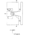
図4に示すように、スピントルク発振子10は、磁化の向きが固着されたスピン注入層10aと、スピン透過率の高い中間層10bと、発振層10cと、を有している。また、スピン注入層10aと磁気シールド64との間に非磁性層10eが設けられ、発振層10cと主磁極62との間に非磁性層10dが設けられている。すなわち、スピントルク発振子10は、非磁性層10e、発振層10c、中間層10b、スピン注入層10a、および非磁性層10dの積層構造を有している。そして、この積層構造の膜面は、磁気記録媒体80に対向する媒体対向面100に対して略直交するともに磁気記録媒体80の進行方向85に対して略直交している。このスピントルク発振子10には、主磁極62と磁気シールド64とを経由して、発振層10cからスピン注入層10aに向かって所定の直流電流を流すことができる。なお、本明細書においては、直流電流はパルス電流も含む。この直流電流がスピントルク発振子10に流れないとき、スピン注入層10aは磁化が膜面に略直交する方向に配向し、発振層10cは磁化が膜面に略平行な方向に配向している。この状態で、スピントルク発振子10に直流電流を流すと、発振層10cの磁化にスピントルクが与えられ、図4に示すように、発振層10cの磁化は強磁性共鳴(磁化の歳差運動)し、高周波磁界が発生される。
As shown in FIG. 4, the
非磁性層10d、10eとしては、Ti、Cu、Ru、Ta、Zr、Nb、Hf、Pt、Pdなどを用いることが好ましい。下地またはキャップ層として機能する。スピントルク発振子10を形成する際に、主磁極62側から順次成膜する場合には非磁性層10eが下地層となり、非磁性層10dがキャップ層となる。これに対して、磁気シールド64側から順次成膜する場合には、非磁性層10dが下地層となり、非磁性層10eがキャップ層となる。非磁性層10e、10dは、主磁極62とスピントルク発振子10との磁気結合および磁気シールド64とスピントルク発振子10との磁気結合をそれぞれ調整する機能を有する。また、非磁性層10e、10dは、スピントルク発振子10の電極として用いることもできる。
As the
中間層10bとしては、非磁性でCu、Au、Ag等のスピン透過率の高い材料を用いることが好ましい。その厚みは0.2nm〜10nmの範囲で、発振層10cとスピン注入層10aとの磁気結合を適度な値に抑制できて、かつできる限り薄い厚みであることが望ましい。その観点から1nm〜3nmの厚みであることが望ましい。
As the
発振層10cとしては、電流が流れていないときに磁化の向きが膜面に略平行である材料を用いることが望ましい、具体的には、CoFe、CoNiFe、NiFe、CoZrNb、FeN、FeSi、FeAlSi、FeCoAl、FeCoSi等の磁気異方性エネルギーKuが比較的小さい合金を用いることが好ましい。その厚みは5nm〜30nmが望ましく、飽和磁束密度Bsは0.5T〜2Tであることが望ましい。
As the
スピン注入層10aとしては、膜面に垂直方向に磁化容易軸を有する磁気異方性エネルギーKuが大きな磁性材料を用いることが好ましい。具体的には
(1)CoCrPt、CoCrTa、CoCrTaPt、CoCrTaNb等のCoCr系合金、
(2)TbFeCo等のRE−TM系アモルファス合金、
(3)Co/Pd、Co/Pt、CoCrTa/Pd等のCo人工格子、
(4)CoPt系やFePt系の合金、
(5)SmCo系合金、あるいは
(6)上記(1)〜(5)と、CoFe合金などの発振層に用いる合金との積層構造、
であることが好ましい。スピン注入層10aの磁気異方性エネルギーKuは1Merg/cm3〜10Merg/cm3であることが望ましい。また、スピン注入層10aの膜厚は10nm〜30nmであることが望ましい。
The
(2) RE-TM amorphous alloys such as TbFeCo,
(3) Co artificial lattice such as Co / Pd, Co / Pt, CoCrTa / Pd,
(4) CoPt and FePt alloys,
(5) SmCo-based alloy, or (6) Laminated structure of (1) to (5) above and an alloy used for an oscillation layer such as a CoFe alloy,
It is preferable that Anisotropy energy K u of the
スピントルク発振子10において、磁化方向を軸とした歳差運動により、安定した発振を実現するためには、発振層10cのトラック幅方向の寸法と媒体対向面100に垂直な方向の寸法とを等しくすることが望ましい。本実施形態においては、図4に示すように、非磁性層10eを挟んで発振層10cと主磁極62とが近接するように積層した。一方、主磁極62からスピン注入層10aへ効率よく磁界を印加するために、スピン注入層10aと主磁極62とを近接するように積層してもよい。
In the
側壁磁性層101は、発振層10cの側面、すなわち非磁性層10eおよび中間層10bと接していない面の少なくとも一部に近接して配置される。図4においては、トラック幅方向に位置する一対の側面に近接して配置した例を示したが、片側の側面にのみ近接して配置しても良い。また、図6(a)に示すように、媒体対向面100とは反対側の発振層10cの面(側面)に近接して配置しても良いし、或いは、図6(b)に示すように、媒体対向面100を除いた発振層10cの全ての面を覆うように近接して配置しても良い。発振層10cの側面のみでなく、非磁性層10eや、スピン注入層10aにまで延在するように配置してもよい。
The side wall
側壁磁性層101としては、概ね記録磁界が加わる方向となる、膜面に対して垂直方向に磁化容易軸を有するCoPt系合金などのハード膜を用いることができる。この方向に磁化した側壁磁性層101により、発振層10cへの記録磁界の低減効果を増大することができる。なお、この場合、側壁磁性層101の磁化容易軸は、スピン注入層10aの磁化の向き(磁化容易軸)と略平行となっている。すなわち、側壁磁性層101とスピン注入層10aとは、ほぼ同方向の磁気異方性を有している。
As the sidewall
また、側壁磁性層101としては、飽和磁束密度Bsが発振層10cのそれよりも大きなFeCo系合金が用いてもよい。これにより、発振層10cよりも側壁磁性層101に記録磁界が加わりやすくなり、発振層10cへの記録磁界の低減効果を更に増大することができる。
Further, as the sidewall
なお、発振層10cに流れる電流が側壁磁性層101に分流しないように、側壁磁性層101と発振層10cとの間には絶縁層102(図5参照)を設けることが望ましい。側壁磁性層101の作製は、垂直通電型のTMR素子またはGMR素子の側壁に絶縁層を介して側壁にCoPt系ハードバイアス膜を作製する方法と同様な方法を用いることにより、行うことができる。しかし、CoPt合金の磁気異方性を膜面に垂直方向とするためには、Ruなどの下地層が用いられる。なお一般に、TMR素子やGMR素子ではCrの下地層が用いられている。
It is desirable to provide an insulating layer 102 (see FIG. 5) between the sidewall
このように構成されたスピントルク発振子10においては、主磁極62からの書き込み磁界の極性が反転して、スピントルク発振子10に加わる磁界が逆方向に加わると、発振周波数が大幅に変動して、場合によっては発振が停止してしまう。この問題を回避するために、主磁極62から発生される磁界の極性の反転に応じてスピン注入層10aの磁化を反転させる動作が望ましい。これにより、発振層10cの磁化も同様に反転することになる。この動作を用いたスピントルク発振子10を、ピンフリップ型スピントルク発振子と呼ぶ。スピン注入層10aに加わる記録磁界よりも、スピン注入層10aの保磁力を小さく設定することにより(当然、発振層10cの保磁力も小さく設定する)、ピンフリップ型スピントルク発振子10が実現できる。スピン注入層10aの保磁力を小さく設定することに加えて側壁磁性層101の保磁力も記録磁界よりも小さく設定することにより、側壁磁性層101の磁化も反転するので、記録磁界の極性に依らず安定した発振層10cへの記録磁界の低減効果が得られる。
In the
また、本実施形態においては、図5に示すように、隣接トラックへの書き込みを防ぐために、トラック進行方向だけでなくトラック幅方向にも磁気シールド64を配置する。すなわち、スピントルク発振子10のトラック進行方向だけでなく、主磁極62およびスピントルク発振子10のトラック幅方向の面に対向して磁気シールド64が設けられている。スピントルク発振子10とトラック幅方向の磁気シールド64との間に側壁磁性層101を配置する。トラック幅方向における磁気シールド64と、主磁極62やスピントルク発振子10との間隔は10nm〜60nmとすることが好ましい。最適間隔は、トラック幅などの諸条件に鑑みて決定される。トラック幅が狭まるにつれて、その間隔も狭める必要がある。磁気シールド64としては、FeCo、NiFe、FeCoNi合金などが用いられる。図5においては、スピントルク発振子10の電極として、主磁極62および磁気シールド64を用いた場合を示したが、非磁性層10dやスピン注入層10aの下地層、キャップ部を厚くしたものを電極として用いても良い。本実施形態のように、スピントルク発振子10に電流を供給する電極の一部に主磁極62を用いて、高周波磁界の発生源である発振層10cと主磁極62との距離を近づけた場合は、主磁極62からの磁界と高周波磁界とが重畳することになるが、記録効率を上昇させることができる。
In the present embodiment, as shown in FIG. 5, in order to prevent writing to adjacent tracks,
以上説明したように、本実施形態によれば、主磁極からの書き込み磁界によるスピントルク発振子の発振特性の変動を低減することができるとともに、スピントルク発振子が受ける主磁極からの書き込み磁界を低減することができる。 As described above, according to the present embodiment, fluctuations in the oscillation characteristics of the spin torque oscillator due to the write magnetic field from the main magnetic pole can be reduced, and the write magnetic field from the main magnetic pole received by the spin torque oscillator can be reduced. Can be reduced.
(変形例)
図7に、第1実施形態の一変形例による磁気記録ヘッドを図7に示す。図7は、本変形例の磁気記録ヘッドを媒体対向面(ABS)から見た平面図である。本変形例においては、発振層10cのトラック幅方向の長さは、スピン注入層10aの長さよりも短くすることにより、発振層10cの、電流が流れる方向の断面積をスピン注入層10aの断面積よりも小さくする。その結果、スピン注入層10aの電流密度を低く保ち、発振層10cのみ電流密度を効率的に増大することができるので、発熱を抑制して大きな電流密度を発振層10cに投入することが可能となる。これにより、第1実施形態よりも信頼性の高いスピントルク発振子とすることができる。
(Modification)
FIG. 7 shows a magnetic recording head according to a modification of the first embodiment. FIG. 7 is a plan view of the magnetic recording head of this modification as viewed from the medium facing surface (ABS). In the present modification, the length of the
なお、本変形例においては、トラック幅方向の長さを変えて断面積を調整したが、スピン注入層10aおよび発振層10cは、媒体対向面100に垂直方向(トラック幅方向およびトラック進行方向に垂直な方向)の長さを変えて断面積を調整しても良い。
In this modification, the cross-sectional area is adjusted by changing the length in the track width direction. However, the
本変形例も第1実施形態と同様に、主磁極からの書き込み磁界によるスピントルク発振子の発振特性の変動を低減することができるとともに、スピントルク発振子が受ける主磁極からの書き込み磁界を低減することができる。 As in the first embodiment, this modification can also reduce fluctuations in the oscillation characteristics of the spin torque oscillator due to the write magnetic field from the main magnetic pole, and reduce the write magnetic field from the main magnetic pole received by the spin torque oscillator. can do.
(第2実施形態)
次に、本発明の第2実施形態による磁気記録ヘッドを、図8を参照して説明する。図8は、本実施形態の磁気記録ヘッドを媒体対向面から見た平面図である。
(Second Embodiment)
Next, a magnetic recording head according to a second embodiment of the invention will be described with reference to FIG. FIG. 8 is a plan view of the magnetic recording head of this embodiment as viewed from the medium facing surface.
本実施形態においては、第1実施形態と異なり、側壁磁性層101を設ける代わりに磁気シールド64で置き換えた構成となっている。すなわち、磁気シールド64が、主磁極62およびスピントルク発振子10のトラック幅方向側に近接して設けられている。本実施形態においては、図8に示すように、スピントルク発振子10を構成する層のうち少なくとも発振層10cおよび非磁性層10eが磁気シールド64に設けられた凹部64a内に位置するように構成されている。この場合、非磁性層10eが凹部64aの底面と接触している。なお、図8においては、主磁極62およびスピントルク発振子10のトラック幅方向の両側面に対向するとともに近接して磁気シールド64を設けているが片側のみ設けるように構成してもよい。
In the present embodiment, unlike the first embodiment, the
本実施形態の磁気記録ヘッドは、トラック幅方向において、スピントルク発振子10と磁気シールド64との間隔a(望ましい値は5nm〜20nm)は、主磁極62と磁気シールド64との間隔b(望ましい値は10nm〜60nm)よりも狭く形成される。この構成により、発振層10cに加わる記録磁界を、発振層10cに隣接する磁気シールド64に導くことにより、発振層10cに加わる過剰な記録磁界の流入を抑制することが可能になる。さらに、主磁極62と発振層10cに隣接する磁気シールド64との間のギャップcは記録ギャップとして作用するので、本実施形態においては、トレーリング側(進行方向からみて最後部側)に磁気シールドが配置された従来の場合に比べて狭い記録ギャップを形成することが可能となる。その結果、線記録密度の向上が可能になる。さらに詳しく説明すると、この磁気ギャップに、媒体面に垂直な方向から傾いた方向に強い記録磁界が発生する。一方、記録に有効な高周波磁界は媒体面内である。その面内成分は、高周波磁界を発生する発振層10cの直下でなく、発振層10cの周辺で最大となる。したがって、斜め成分の記録磁界と面内高周波磁界の両者を磁気記録媒体の小さな領域に重畳して加えることが可能となる。
In the magnetic recording head of this embodiment, in the track width direction, the distance a between the
本実施形態においては、図8に示すように、主磁極62と発振層10cとの間にスピン注入層10aが配置された構成となっている。この場合、スピン注入層10aには大きな記録磁界が加わるので、ピンフリップ型スピントルク発振子10を用いた場合に適する。
In the present embodiment, as shown in FIG. 8, the
一方、図9に示すように、主磁極62とスピン注入層10aとの間に発振層10cが配置される本実施形態の第1の変形例による磁気記録ヘッドにおいては、発振層10cと磁気ギャップcを接近させることが容易であり、磁気ギャップcでの高周波磁界の強度を増大できる利点を有する。この変形例においては、スピントルク発振子10の発振層10cばかりでなく、中間層10b、スピン注入層10a、および非磁性層10dも磁気シールド64に設けられた凹部64a内に位置するように構成されている。この場合、非磁性層10dが凹部64aの底面と接触している。
On the other hand, as shown in FIG. 9, in the magnetic recording head according to the first modification of the present embodiment in which the
図8に示す第2実施形態の磁気記録ヘッドにおいて、磁気ギャップcを狭めるために、図10に示す第2実施形態の第2変形例のように、スピン注入層10aの側部にも磁気シールド64が存在するような構成を用いることも可能である。この場合、磁気シールド64内に設けられる凹部64aは、磁気シールド64をトラック進行方向に貫通した構成となる。そして、非磁性層10eが、発振層10cから凹部64aを通って、磁気シールド64の主磁極62と反対側の面を突き抜けて延在するように構成されている。この実施形態においては、スピントルク発振子10には、電極を兼用した主磁極62と、電極を兼用した非磁性層10eとの間に電流を通電する。磁気シールド64の凹部をトラック進行方向に貫通させたので、電極を兼用した非磁性層10eを設けるスペースが確保できる。本実施形態と異なり、非磁性層10eの代わりに磁気シールド64を電極として用いると、スピントルク発振子10との接続部以外では、主磁極62と磁気シールド64との間での絶縁が必要となり、そこに新たな磁気ギャップが発生して、記録効率の低下を引き起こすことが懸念される。これに対して、本実施形態では、磁気シールド64と主磁極62との絶縁は必ずしも必要としないので、この問題も回避できる。
In the magnetic recording head of the second embodiment shown in FIG. 8, in order to narrow the magnetic gap c, a magnetic shield is also formed on the side of the
また、この第2変形例の磁気記録ヘッドにおいて、図11に示すように、主磁極62にスピン注入層10aの一部を埋め込んだ、第2実施形態の第3変形例による磁気記録ヘッドのように構成してもよい。この場合も第2変形例と同様の効果を得ることができる。第2実施形態および第1変形例においては、主磁極62の媒体対向面における平面形状は、トレーリング側に向かうにつれて幅が狭くなる台形であったが、第2実施形態の第2および第3変形例においては、長方形となっているが、第1実施形態のような台形構造を用いても良い。
Further, in the magnetic recording head of the second modification example, as shown in FIG. 11, like the magnetic recording head according to the third modification example of the second embodiment in which a part of the
以上説明したように、第2実施形態およびその変形例においては、側壁非磁性層を設ける代わりに磁気シールド64をスピントルク発振子10の発振層10cの側面に近接して配置したので、第1実施形態と同様に、主磁極からの書き込み磁界によるスピントルク発振子の発振特性の変動を低減することができるとともに、スピントルク発振子が受ける主磁極からの書き込み磁界を低減することができる。
As described above, in the second embodiment and the modification thereof, the
(第3実施形態)
次に、本発明の第3実施形態による磁気記録再生装置について説明する。図1乃至図11に関して説明した本発明の各実施形態およびその変形例による磁気記録ヘッドは、例えば、記録再生一体型のヘッドスタックアセンブリに組み込まれ、磁気記録再生装置に搭載することができる。本実施形態の磁気記録再生装置は、磁気記録媒体と、上記実施形態のいずれかに記載の磁気記録ヘッドと、上記磁気記録媒体と上記磁気記録ヘッドとが浮上または接触の状態で対峙しながら相対的に移動するように制御する移動制御部と、上記磁気記録ヘッドを上記磁気記録媒体の所定記録位置に位置するように制御する位置制御部と、上記磁気記録ヘッドを用いて上記磁気記録媒体への書き込み信号および上記磁気記録媒体からの読み出し信号を処理する信号処理手段と、を備えている。
(Third embodiment)
Next explained is a magnetic recording / reproducing apparatus according to the third embodiment of the invention. The magnetic recording head according to each of the embodiments of the present invention described with reference to FIGS. 1 to 11 and the modification thereof can be incorporated into a recording / reproducing integrated head stack assembly and mounted on a magnetic recording / reproducing apparatus, for example. The magnetic recording / reproducing apparatus according to the present embodiment includes a magnetic recording medium, the magnetic recording head according to any of the above-described embodiments, and the magnetic recording medium and the magnetic recording head while facing each other in a floating or contact state. A movement control unit for controlling the magnetic recording head to move, a position control unit for controlling the magnetic recording head to be positioned at a predetermined recording position of the magnetic recording medium, and the magnetic recording medium using the magnetic recording head. Signal processing means for processing the write signal and the read signal from the magnetic recording medium.
図12は、このような磁気記録再生装置の概略構成を例示する要部斜視図である。すなわち、本実施形態の磁気記録再生装置150は、ロータリーアクチュエータを用いた形式の装置である。図12において、長手記録用または垂直記録用磁気ディスク200は、スピンドル152に装着され、図示しない駆動装置制御部からの制御信号に応答する図示しないモータにより矢印Aの方向に回転する。磁気ディスク200は、垂直記録用の記録層と、軟磁性裏打ち層とを有した、2層の磁気記録媒体である。磁気ディスク200に格納する情報の記録再生を行うヘッドスライダー153は、薄膜状のサスペンション154の先端に取り付けられている。ここで、ヘッドスライダー153は、例えば、前述したいずれかの実施形態にかかる磁気記録ヘッドをその先端付近に搭載している。サスペンション154は、アクチュエータアーム155の一端に接続されている。アクチュエータアーム155の他端にはリニアモータの一種であるボイスコイルモータ156が設けられている。ボイスコイルモータ156は、アクチュエータアーム155のボビン部に巻き上げられた図示しない駆動コイルと、この駆動コイルを挟むように、対向して配置された永久磁石および対向ヨークからなる磁気回路とから構成することができる。
FIG. 12 is a main part perspective view illustrating a schematic configuration of such a magnetic recording / reproducing apparatus. That is, the magnetic recording / reproducing
アクチュエータアーム155は、軸受部157の上下2箇所に設けられた図示しないボールベアリングによって保持され、ボイスコイルモータ156により回転摺動が自在にできるようになっている。
The
磁気ディスク200が回転すると、ヘッドスライダー153の媒体対向面(ABS)は磁気ディスク200の表面から所定の浮上量をもって保持される。
When the
また、本実施形態の磁気記録再生装置においては、磁気記録ヘッドを用いて磁気記録媒体200への信号の書き込みと読み出しを行う、図示しない信号処理部190が設けられている。信号処理部190は、例えば、図12に例示した磁気記録再生装置の図面中の背面側に設けられる。信号処理部190の入出力線は、ヘッドスタックアセンブリ160の電極パッドに接続され、磁気記録ヘッドと電気的に結合される。
Further, in the magnetic recording / reproducing apparatus of the present embodiment, a signal processing unit 190 (not shown) that performs writing and reading of signals to and from the
このように構成された本実施形態の磁気記録再生装置において、磁気記録媒体に加わる高周波磁界Hacと記録磁界Hrの比(=Hac/Hr)が1より小さくなる磁気ヘッドを用いる場合には、磁気記録媒体のディスクの回転方向、すなわち磁気記録媒体の移動方向は、最初に主磁極を通り、次にスピントルク発振子を通過するトレーリング記録を用いることが望ましい。すなわち、このトレーリング記録は、スピントルク発振子が磁気記録媒体の進行方向のトレーリング側(進行方向からみて最後部側)に配置される。この場合、記録磁界が弱まるスピントルク発振子の近傍領域(高周波磁界が強い)では記録されないことになり、記録は主磁極の近傍(記録磁界が強い)の磁気記録媒体の領域で決定されるために、高い線記録密度の記録が可能となる。一方、高周波磁界が主となり記録磁界が従となる、すなわち高周波磁界Hacと記録磁界Hrの比(=Hac/Hr)が1より大きくなる磁気記録ヘッドでは、逆に、磁気記録媒体のディスクの回転方向、すなわち磁気記録媒体の移動方向は、最初にスピントルク発振子を通り、次に主磁極を通過するリーディング記録を用いることが望ましい。すなわち、このリーディング記録は、スピントルク発振子が磁気記録媒体の進行方向のリーディング側(進行方向からみて最前部側)に配置される。この場合、高周波磁界が弱まる主磁極の近傍領域では記録されないことになり、記録はスピントルク発振子の近傍の磁気記録媒体の領域で決定されるために、高い線記録密度の記録が可能となる。 In the magnetic recording / reproducing apparatus of the present embodiment configured as described above, when using a magnetic head in which the ratio of the high frequency magnetic field Hac applied to the magnetic recording medium to the recording magnetic field Hr (= Hac / Hr) is less than 1, the magnetic head It is desirable to use trailing recording in which the rotation direction of the disk of the recording medium, that is, the moving direction of the magnetic recording medium, first passes through the main magnetic pole and then passes through the spin torque oscillator. That is, in this trailing recording, the spin torque oscillator is arranged on the trailing side in the traveling direction of the magnetic recording medium (the rearmost side as viewed from the traveling direction). In this case, recording is not performed in the region near the spin torque oscillator where the recording magnetic field is weakened (the high frequency magnetic field is strong), and recording is determined in the region of the magnetic recording medium near the main magnetic pole (the recording magnetic field is strong). In addition, recording with a high linear recording density is possible. On the other hand, in the magnetic recording head in which the high frequency magnetic field is the main and the recording magnetic field is the subordinate, that is, the ratio of the high frequency magnetic field Hac to the recording magnetic field Hr (= Hac / Hr) is greater than 1, conversely, the rotation of the disk of the magnetic recording medium For the direction, that is, the moving direction of the magnetic recording medium, it is desirable to use leading recording that first passes through the spin torque oscillator and then passes through the main magnetic pole. That is, in this leading recording, the spin torque oscillator is arranged on the leading side in the traveling direction of the magnetic recording medium (the frontmost side when viewed from the traveling direction). In this case, recording is not performed in the vicinity of the main magnetic pole where the high-frequency magnetic field is weakened, and recording is determined in the area of the magnetic recording medium in the vicinity of the spin torque oscillator, so that recording with a high linear recording density is possible. .
また、本発明の第3実施形態による磁気記録再生装置においては、スピントルク発振子の発振周波数は、後述する磁気記録媒体の記録磁性層を構成する記録磁性粒または記録磁性ドットの強磁性共鳴周波数と略等しいことが好ましい。 In the magnetic recording / reproducing apparatus according to the third embodiment of the present invention, the oscillation frequency of the spin torque oscillator is the ferromagnetic resonance frequency of the recording magnetic grains or recording magnetic dots constituting the recording magnetic layer of the magnetic recording medium described later. Is preferably approximately equal to
以上、具体例を参照しつつ、本発明の実施形態について説明した。しかし、本発明は、これらの具体例に限定されるものではない。例えば、磁気記録媒体として用い得るものは、図1に例示した磁気記録媒体80には限定されない。
The embodiments of the present invention have been described above with reference to specific examples. However, the present invention is not limited to these specific examples. For example, what can be used as a magnetic recording medium is not limited to the
図13に、本発明の各実施形態の磁気記録再生装置に用いることのできる磁気記録媒体180の第1具体例を示す。基板上(図示せず)にソフトアンダーレーヤ184、中間層183、記録磁性層182、記録磁性層181が順次積層され、その表面にはオーバコート(ダイヤモンド状カーボンなど、図示せず)が積層される。磁気記録ヘッドから離れた下層の記録磁性層182の磁気異方性に比べて、磁気記録ヘッドに近い上層の記録磁性層181の磁気異方性は小さいことが望ましい。下層の記録磁性層182は、膜面に垂直方向に磁化容易軸を有するが、上層の記録磁性層181は膜面内、膜面に垂直あるいはその中間方向の磁気異方性であっても良い。記録磁性層182には、記録磁性層181に比べて磁気異方性が大きな材料が用いられる。記録磁性層182として例えばCoCrPt合金に約10%の非磁性酸化物(SiO2またはAlOx)を混入させた垂直配向硬磁性膜を用いることができる。たとえばCo74Cr10Pt16に約10%のSiO2を混入させた垂直配向硬磁性膜は約14kOeの磁気異方性磁界Hkを有する。さらに磁気異方性磁界Hkの高いFePtなどを用いてもよい、記録磁性層181としてはCoに非磁性酸化物たとえばSiO2を混入させ、記録層上にhcp(六方最密充填)成長させた硬磁性膜を用いることができる。このような硬磁性膜は約6.8kOeのHkを有する。
FIG. 13 shows a first specific example of a
SiO2を含まないCo系合金を用いても良い。記録磁性層181の厚みt1と記録磁性層182の厚みt2は、t2/t1が0.5〜4の範囲にあることが望ましい。記録磁性層181と記録磁性層182との間に、交換結合を調整する層を設けても良い。
A Co-based alloy not containing SiO 2 may be used. The thickness t1 of the recording
シミュレーションなどにより鋭意検討した結果、図13に示すような2層媒体では、記録磁性層181の強磁性共鳴周波数に高周波磁界の周波数を合わせることにより、最も効率よく、小さな記録磁界で記録可能となることを見出した。記録磁性層181の強磁性共鳴周波数は、磁気異方性が小さいので、従来の単層の磁気記録媒体の共鳴周波数に比べて低下する。一方、今まで説明してきた本発明の各実施形態およびその変形例による磁気記録ヘッドを用いると、発振層に加わる記録磁界が低減される。シミュレーションなどに鋭意検討した結果、高周波磁界の周波数は概ね発振層に加わる記録磁界に比例することが本発明者達によって見出された。したがって、高周波磁界周波数の低減に適した本発明の各実施形態およびその変形例による磁気記録ヘッドを、図13に示す磁気記録媒体を用いた磁気記録再生装置に適用することにより、磁気記録媒体の共鳴周波数と高周波磁界周波数とのマッチングが良好となる。その結果、より容易な記録が可能となり、高い記録密度の磁気記録再生装置が実現できる。また、発振層に加わる記録磁界を低減して、高周波磁界周波数を低減した上記各実施形態の磁気記録ヘッドと、図13に示す上記2層構成の磁気記録媒体を組み合わせることにより、従来では困難であった高記録密度に適した大きな磁気異方性を有する微細結晶粒径の磁気記録媒体にも十分な記録が可能となる。
As a result of intensive studies by simulations and the like, in the two-layer medium as shown in FIG. 13, by adjusting the frequency of the high frequency magnetic field to the ferromagnetic resonance frequency of the recording
第1及び第2実施形態およびその変形例による磁気記録ヘッドを用いると、場合によってはトラック幅端部にも大きな高周波磁界が加わる。そのため、隣接トラックとの間に非磁性領域を設けた媒体との組み合わせが望ましい。そのような媒体として、いわゆるディスクリートトラック媒体が挙げられる。このディスクリートトラック媒体は、トラック進行方向には結晶粒界以外に非磁性領域は存在しない。また、トラック進行方向にも明確な非磁性領域を有する、いわゆるパターンド媒体でも良い。さらに、スピントルク発振子のトラック幅方向に、スピントルク発振子との間隔が狭いサイド磁気シールドを設けた実施形態(たとえば第2実施形態)による磁気記録ヘッドでは、トラック幅両端にて、強い記録磁界が発生し易いく、トラック幅端部にそれぞれ磁性パターン部が存在するパターンド媒体が望ましい。このパターンド媒体では、隣接するトラック幅方向の2つの磁性パターン部を一つの情報単位として記録することになる。これらの磁気記録媒体を第2乃至第4具体例として以下に説明する。 When the magnetic recording heads according to the first and second embodiments and the modifications thereof are used, a large high-frequency magnetic field is applied to the end portion of the track width in some cases. Therefore, a combination with a medium in which a nonmagnetic region is provided between adjacent tracks is desirable. An example of such a medium is a so-called discrete track medium. This discrete track medium has no nonmagnetic regions other than crystal grain boundaries in the track traveling direction. Also, a so-called patterned medium having a clear nonmagnetic region in the track traveling direction may be used. Further, in the magnetic recording head according to the embodiment (for example, the second embodiment) in which the side magnetic shield having a narrow interval with the spin torque oscillator is provided in the track width direction of the spin torque oscillator, strong recording is performed at both ends of the track width. A patterned medium that is easy to generate a magnetic field and has a magnetic pattern portion at each track width end is desirable. In this patterned medium, two magnetic pattern portions in the adjacent track width direction are recorded as one information unit. These magnetic recording media will be described below as second to fourth specific examples.
図14に、本発明の磁気記録再生装置に用いることができる磁気記録媒体の第2具体例を示す。 FIG. 14 shows a second specific example of a magnetic recording medium that can be used in the magnetic recording / reproducing apparatus of the present invention.
すなわち、本具体例の磁気記録媒体201は、非磁性体(あるいは空気)287により互いに分離された垂直配向した多粒子系の磁性ディスクリートトラック286を有する。この磁気記録媒体201がスピンドルモータ204により回転され、媒体走行方向に向けて移動する際に、ヘッドスライダー203に搭載された磁気記録ヘッド205により、記録磁化284を形成することができる。なお、ヘッドスライダー203はサスペンション202の先端に取り付けられている。このサスペンション202には、信号の書き込みおよび読み取り用のリード線を有し、これらのリード線とヘッドスライダー203に組み込まれた磁気ヘッド205の各電極とが電気的に接続される。
That is, the
スピントルク発振子の記録トラック幅方向の幅(TS)を記録トラックの幅(TW)以上で、且つ記録トラックピッチ(TP)以下とすることによって、スピントルク発振子から発生する漏れ高周波磁界による隣接記録トラックの保磁力の低下を大幅に抑制することができる。このため、本具体例の磁気記録媒体201では、記録したい記録トラックのみを効果的に高周波磁界アシスト記録することができる。特に、高周波磁界は周波数が高くシールド効果がないため、トラック幅方向に設けたシールドで隣接記録トラックへの記録滲みを低減することが困難である。本発明の各実施形態およびその変形例による磁気ヘッドでは、図14で示した磁気記録媒体を用いた磁気記録再生装置により、隣接記録トラックのイレーズ問題を解決することができる。また、本具体例によれば、従来の磁気記録ヘッドでは書き込み不可能なFePtやSmCo等の高磁気異方性エネルギーKuの媒体磁性材料を用いることによって、媒体磁性粒子のさらなる微細化(ナノメーター級のサイズ)が可能となり、記録トラック方向(ビット方向)においても、従来よりも遥かに線記録密度の高い磁気記録装置を実現することができる。
By setting the width (TS) of the spin torque oscillator in the recording track width direction to be equal to or larger than the recording track width (TW) and equal to or smaller than the recording track pitch (TP), it is adjacent to the leakage high frequency magnetic field generated from the spin torque oscillator. A decrease in the coercivity of the recording track can be greatly suppressed. For this reason, in the
図15に、本発明の各実施形態の磁気記録ヘッドに用いることができる磁気記録媒体の第3具体例を示す。すなわち、本具体例の磁気記録媒体201は、非磁性体287により分離された磁性ディスクリートビット288を有する。この磁気記録媒体201がスピンドルモータ204により回転され、媒体走行方向に向けて移動する際に、ヘッドスライダー203に搭載された磁気記録ヘッド205により、記録磁化を形成することができる。
FIG. 15 shows a third specific example of a magnetic recording medium that can be used in the magnetic recording head of each embodiment of the invention. In other words, the
この具体例においても、スピントルク発振子の記録トラック幅方向の幅(TS)を記録トラックの幅(TW)以上で、且つ記録トラックピッチ(TP)以下とすることによって、スピントルク発振子から発生する漏れ高周波磁界による隣接記録トラックの保磁力の低下を大幅に抑制することができるため、記録したい記録トラックのみを効果的に高周波磁界アシスト記録することができる。 Also in this specific example, when the width (TS) in the recording track width direction of the spin torque oscillator is equal to or larger than the recording track width (TW) and equal to or smaller than the recording track pitch (TP), the spin torque oscillator generates from Since the decrease in the coercive force of the adjacent recording track due to the leaking high frequency magnetic field can be significantly suppressed, only the recording track to be recorded can be effectively recorded with the high frequency magnetic field assist.
図16に、本発明の各実施形態の磁気記録ヘッドに用いることができる磁気記録媒体の第4具体例を示す。図15と同様な磁性ディスクリードビッド288により磁気記録媒体は構成される。図16では、トラック幅に2つのピットを1つの情報単位として記録することを特徴とする。図8〜図11に示した磁気ヘッドを用いると、トラック幅方向の両端に磁気ギャップが2つ形成される。この磁気ギャップを、図16に示す隣接する2つのピットに合わせることにより、2つのビットのみが同時に記録できる。2つのピット間は非磁性領域なので、記録磁界の強度が不十分による磁気情報の乱れに起因したノイズを発生することがない。したがって、より高SN比に磁気記録再生装置が実現できる。 FIG. 16 shows a fourth specific example of a magnetic recording medium that can be used in the magnetic recording head of each embodiment of the present invention. A magnetic recording medium is constituted by a magnetic disk lead bid 288 similar to that shown in FIG. In FIG. 16, two pits are recorded as one information unit in the track width. When the magnetic head shown in FIGS. 8 to 11 is used, two magnetic gaps are formed at both ends in the track width direction. By aligning this magnetic gap with two adjacent pits shown in FIG. 16, only two bits can be recorded simultaneously. Since the area between the two pits is a non-magnetic area, noise due to magnetic information disturbance due to insufficient recording magnetic field strength is not generated. Therefore, a magnetic recording / reproducing apparatus can be realized with a higher SN ratio.
以上説明したように、本発明の各実施形態によれば、発振層に加わる主磁極からの磁界を低減することができる。その結果、第1に、高周波磁界の発生に必要なスピントルク発振子に流す電流を低減することが可能となるので、電流による発熱を低減することができる。第2に、主磁極からの書き込み磁界によるスピントルク発振子の発振特性の変動を低減することができる。第2の効果は、正負の記録磁界に応じてスピン発振子の磁化が反転するピンフリップ型スピントルク発振子を用いた場合に顕著となる。第3に、高周波磁界の周波数を低減できるので、磁気異方性が異なる2層からなる磁気記録媒体を用いることにより、大きな記録効率のアップ、より小さな磁界による媒体書込みが可能となる。 As described above, according to each embodiment of the present invention, the magnetic field from the main magnetic pole applied to the oscillation layer can be reduced. As a result, first, it is possible to reduce the current flowing through the spin torque oscillator necessary for generating the high-frequency magnetic field, so that heat generation due to the current can be reduced. Second, fluctuations in the oscillation characteristics of the spin torque oscillator due to the write magnetic field from the main pole can be reduced. The second effect becomes prominent when a pin-flip type spin torque oscillator in which the magnetization of the spin oscillator is reversed in accordance with positive and negative recording magnetic fields is used. Third, since the frequency of the high-frequency magnetic field can be reduced, by using a magnetic recording medium having two layers having different magnetic anisotropies, the recording efficiency can be greatly increased, and the medium can be written with a smaller magnetic field.
5 磁気記録ヘッド
10 スピントルク発振子
10a スピン注入層
10b 中間層
10c 発振層
10d 非磁性層
10e 非磁性層
60 書き込みヘッド部
61 磁気コア
62 主磁極(記録磁極)
64 磁気シールド
67 励磁コイル
70 再生ヘッド部
71 磁気再生素子
72a 磁気シールド
72b 磁気シールド
80 磁気記録媒体
81 媒体基板
82 磁気記録層
85 磁気記録媒体の移動方向
100 媒体対向面
101 側壁磁性層
153 ヘッドスライダー
153A 空気流入側
153B 空気流出側
158 HGA(磁気ヘッドアセンブリ)
160 ヘッドスタックアセンブリ
180 磁気記録媒体
5
64
160
Claims (17)
第1および第2磁性層と、前記第1磁性層と前記第2磁性層との間に設けられる中間層とを有し、前記第1および第2磁性層間に電流を通電して前記第2磁性層から高周波磁界を発生するスピントルク発振子と、
前記第2磁性層の側面の少なくとも一部に近接して配置される第3磁性層と、
を備え、
前記第1磁性層および前記第3磁性層の保磁力が、前記第1磁性層および前記第3磁性層に加わる前記記録磁極からの磁界よりも小さいことを特徴とする磁気記録部を有する磁気ヘッドアセンブリ。 Recording magnetic pole,
First and second magnetic layers, and an intermediate layer provided between the first magnetic layer and the second magnetic layer, and by passing a current between the first and second magnetic layers, A spin torque oscillator that generates a high-frequency magnetic field from a magnetic layer;
A third magnetic layer disposed proximate to at least a part of a side surface of the second magnetic layer;
Equipped with a,
A magnetic head having a magnetic recording unit , wherein coercive forces of the first magnetic layer and the third magnetic layer are smaller than a magnetic field from the recording magnetic pole applied to the first magnetic layer and the third magnetic layer assembly.
第1および第2磁性層と、前記第1磁性層と前記第2磁性層との間に設けられる中間層とを有し、前記第1および第2磁性層間に電流を通電して前記第2磁性層から高周波磁界を発生するスピントルク発振子と、
前記第2磁性層の側面の少なくとも一部に近接して配置される第3磁性層と、
を備え、
前記第3磁性層は、前記第1磁性層と概ね同方向の磁気異方性を有することを特徴とする磁気記録部を有する磁気ヘッドアセンブリ。 Recording magnetic pole,
First and second magnetic layers, and an intermediate layer provided between the first magnetic layer and the second magnetic layer, and by passing a current between the first and second magnetic layers, A spin torque oscillator that generates a high-frequency magnetic field from a magnetic layer;
A third magnetic layer disposed proximate to at least a part of a side surface of the second magnetic layer;
With
The magnetic head assembly having a magnetic recording portion, wherein the third magnetic layer has magnetic anisotropy in substantially the same direction as the first magnetic layer.
第1および第2磁性層と、前記第1磁性層と前記第2磁性層との間に設けられる中間層とを有し、前記第1および第2磁性層間に電流を通電して前記第2磁性層から高周波磁界を発生するスピントルク発振子と、
前記記録磁極および前記第2磁性層のトラック幅方向の面に対向して設けられる磁気シールドと、
を備え、
前記磁気シールドと前記第2磁性層との間隔が、前記記録磁極と前記磁気シールドとの間隔よりも狭いことを特徴とする磁気ヘッドアセンブリ。 Recording magnetic pole,
First and second magnetic layers, and an intermediate layer provided between the first magnetic layer and the second magnetic layer, and by passing a current between the first and second magnetic layers, A spin torque oscillator that generates a high-frequency magnetic field from a magnetic layer;
A magnetic shield provided facing the surfaces of the recording magnetic pole and the second magnetic layer in the track width direction;
With
A magnetic head assembly, wherein an interval between the magnetic shield and the second magnetic layer is narrower than an interval between the recording magnetic pole and the magnetic shield.
請求項1乃至9のいずれかに記載の磁気ヘッドアセンブリと、
前記磁気記録媒体と前記磁気ヘッドアセンブリとが浮上または接触の状態で対峙しながら相対的に移動するように制御する移動制御部と、
前記磁気ヘッドアセンブリを前記磁気記録媒体の所定記録位置に位置するように制御する位置制御部と、
前記磁気ヘッドアセンブリを用いて前記磁気記録媒体への書き込み信号および前記磁気記録媒体からの読み出し信号を処理する信号処理手段と、
を備えることを特徴とする磁気記録再生装置。 A magnetic recording medium;
A magnetic head assembly according to any one of claims 1 to 9 ,
A movement control unit for controlling the magnetic recording medium and the magnetic head assembly to move relatively while facing each other in a floating or contact state;
A position controller for controlling the magnetic head assembly to be positioned at a predetermined recording position of the magnetic recording medium;
Signal processing means for processing a write signal to the magnetic recording medium and a read signal from the magnetic recording medium using the magnetic head assembly;
A magnetic recording / reproducing apparatus comprising:
Priority Applications (2)
| Application Number | Priority Date | Filing Date | Title |
|---|---|---|---|
| JP2008160856A JP5377893B2 (en) | 2008-06-19 | 2008-06-19 | Magnetic head assembly and magnetic recording / reproducing apparatus |
| US12/457,657 US8320079B2 (en) | 2008-06-19 | 2009-06-17 | Magnetic head assembly and magnetic recording/reproducing apparatus |
Applications Claiming Priority (1)
| Application Number | Priority Date | Filing Date | Title |
|---|---|---|---|
| JP2008160856A JP5377893B2 (en) | 2008-06-19 | 2008-06-19 | Magnetic head assembly and magnetic recording / reproducing apparatus |
Publications (2)
| Publication Number | Publication Date |
|---|---|
| JP2010003351A JP2010003351A (en) | 2010-01-07 |
| JP5377893B2 true JP5377893B2 (en) | 2013-12-25 |
Family
ID=41504931
Family Applications (1)
| Application Number | Title | Priority Date | Filing Date |
|---|---|---|---|
| JP2008160856A Expired - Fee Related JP5377893B2 (en) | 2008-06-19 | 2008-06-19 | Magnetic head assembly and magnetic recording / reproducing apparatus |
Country Status (2)
| Country | Link |
|---|---|
| US (1) | US8320079B2 (en) |
| JP (1) | JP5377893B2 (en) |
Families Citing this family (87)
| Publication number | Priority date | Publication date | Assignee | Title |
|---|---|---|---|---|
| JP2008277586A (en) * | 2007-04-27 | 2008-11-13 | Toshiba Corp | Magnetic element, magnetic recording head and magnetic recording apparatus |
| US8994587B2 (en) | 2010-05-14 | 2015-03-31 | Qualcomm Incorporated | Compressed sensing for navigation data |
| JP4358279B2 (en) | 2007-08-22 | 2009-11-04 | 株式会社東芝 | Magnetic recording head and magnetic recording apparatus |
| JP2009070439A (en) * | 2007-09-11 | 2009-04-02 | Toshiba Corp | Magnetic recording head and magnetic recording device |
| JP2009080875A (en) | 2007-09-25 | 2009-04-16 | Toshiba Corp | Magnetic head and magnetic recording system |
| JP5361259B2 (en) * | 2008-06-19 | 2013-12-04 | 株式会社東芝 | Spin torque oscillator, magnetic recording head, magnetic head assembly, and magnetic recording apparatus |
| JP5377893B2 (en) * | 2008-06-19 | 2013-12-25 | 株式会社東芝 | Magnetic head assembly and magnetic recording / reproducing apparatus |
| JP2010040060A (en) * | 2008-07-31 | 2010-02-18 | Toshiba Corp | Magnetic head for high-frequency field assist recording and magnetic recording apparatus using the same |
| JP2010040126A (en) | 2008-08-06 | 2010-02-18 | Toshiba Corp | Magnetic recording head, magnetic head assembly, and magnetic recording device |
| JP5142923B2 (en) * | 2008-09-30 | 2013-02-13 | 株式会社東芝 | Magnetic oscillation element, magnetic sensor, and magnetic recording / reproducing apparatus |
| JP5173750B2 (en) * | 2008-11-06 | 2013-04-03 | 株式会社東芝 | Spin torque oscillator, magnetic recording head, magnetic head assembly, and magnetic recording apparatus |
| JP5558698B2 (en) | 2008-11-28 | 2014-07-23 | 株式会社東芝 | Magnetic recording head, magnetic head assembly, magnetic recording apparatus, and magnetic recording method |
| JP4649519B2 (en) * | 2009-03-13 | 2011-03-09 | 株式会社東芝 | Magnetic disk drive and magnetic head drive control method |
| US8547661B2 (en) * | 2009-10-21 | 2013-10-01 | Headway Technologies, Inc. | MAMR head with self-aligned write element and microwave field generator |
| JPWO2011052021A1 (en) | 2009-10-30 | 2013-03-14 | 株式会社東芝 | Magnetic recording device |
| JP4975836B2 (en) | 2010-02-19 | 2012-07-11 | 株式会社東芝 | Magnetic recording head and magnetic recording / reproducing apparatus using the same |
| JP2012119027A (en) * | 2010-11-30 | 2012-06-21 | Toshiba Corp | Magnetic recording head, magnetic head assembly, and magnetic recorder |
| JP5135419B2 (en) | 2010-12-03 | 2013-02-06 | 株式会社東芝 | Spin torque oscillator, manufacturing method thereof, magnetic recording head, magnetic head assembly, magnetic recording apparatus |
| JP5412415B2 (en) | 2010-12-08 | 2014-02-12 | 株式会社日立製作所 | Magnetic recording head, manufacturing method thereof, and magnetic disk apparatus |
| US8542463B2 (en) * | 2011-06-10 | 2013-09-24 | Headway Technologies, Inc. | Non-uniform write gap perpendicular writer for shingle writing |
| JP5269957B2 (en) | 2011-07-14 | 2013-08-21 | 株式会社東芝 | RECORDING HEAD AND DISK DEVICE EQUIPPED WITH THE SAME |
| US8634163B2 (en) | 2011-07-27 | 2014-01-21 | HGST Netherlands B.V. | Dual reverse microwave assisted magnetic recording (MAMR) and systems thereof |
| JP5890983B2 (en) * | 2011-08-29 | 2016-03-22 | 株式会社日立製作所 | Magnetic recording device |
| JP2013051018A (en) * | 2011-08-31 | 2013-03-14 | Hitachi Ltd | Microwave assisted magnetic recording head and magnetic recording device with spin torque oscillator |
| US8553362B2 (en) | 2011-09-06 | 2013-10-08 | HGST Netherlands B.V. | Magnetic recording head with adjacent track interference suppresion by novel microwave-assisted magnetic recording element |
| JP5364135B2 (en) * | 2011-09-06 | 2013-12-11 | 株式会社日立製作所 | Magnetic recording head, magnetic recording apparatus |
| JP5117606B1 (en) * | 2011-09-13 | 2013-01-16 | 株式会社日立製作所 | Magnetic recording head, manufacturing method thereof, and magnetic disk apparatus |
| JP5172004B1 (en) * | 2011-09-20 | 2013-03-27 | 株式会社日立製作所 | Magnetic recording head and magnetic recording apparatus |
| JP5416746B2 (en) * | 2011-09-29 | 2014-02-12 | 株式会社日立製作所 | Magnetic storage device, head drive control device, and head drive control method |
| US8456967B1 (en) | 2011-10-12 | 2013-06-04 | Western Digital (Fremont), Llc | Systems and methods for providing a pole pedestal for microwave assisted magnetic recording |
| US8630064B2 (en) | 2011-11-11 | 2014-01-14 | HGST Netherlands B.V. | Magnetic write head with novel shield structure having latterally extending trailing gap layer and concaved side gap |
| US8547656B2 (en) | 2012-02-21 | 2013-10-01 | HGST Netherlands B.V. | Spin-torque oscillator (STO) for microwave-assisted magnetic recording (MAMR) and methods of use thereof |
| US8472135B1 (en) | 2012-03-09 | 2013-06-25 | HGST Netherlands B.V. | Microwave-assisted magnetic recording head having a current confinement structure |
| JP5701801B2 (en) * | 2012-03-22 | 2015-04-15 | 株式会社東芝 | Magnetic recording head, head gimbal assembly including the same, and disk device |
| JP5606482B2 (en) | 2012-03-26 | 2014-10-15 | 株式会社東芝 | Magnetic head, magnetic head assembly, magnetic recording / reproducing apparatus, and magnetic head manufacturing method |
| JP2013254547A (en) * | 2012-06-08 | 2013-12-19 | Hitachi Ltd | Microwave assisted recording magnetic head and magnetic recording/reproducing apparatus |
| JP2014017030A (en) | 2012-07-06 | 2014-01-30 | Toshiba Corp | Magnetic head, manufacturing method thereof, and magnetic recording and reproducing device |
| US8908330B1 (en) | 2012-12-21 | 2014-12-09 | Western Digital Technologies, Inc. | Spin torque oscillator for microwave assisted magnetic recording with optimal geometries |
| US9355654B1 (en) | 2012-12-21 | 2016-05-31 | Western Digital Technologies, Inc. | Spin torque oscillator for microwave assisted magnetic recording with increased damping |
| US9412398B2 (en) * | 2013-08-21 | 2016-08-09 | HGST Netherlands B.V. | Shield with uniform magnetic properties for a perpendicular magnetic recording head |
| US9202528B2 (en) | 2013-09-27 | 2015-12-01 | HGST Netherlands B.V. | MAMR head with recessed STO |
| US9135933B2 (en) | 2013-11-08 | 2015-09-15 | HGST Netherlands B.V. | Tapered write head for MAMR |
| JP2015149112A (en) * | 2014-02-07 | 2015-08-20 | 株式会社東芝 | Magnetic recording head and disk unit including the same |
| US9406316B2 (en) | 2014-05-15 | 2016-08-02 | HGST Netherlands B.V. | Asymmetric MAMR head with self-aligned spin torque oscillator along flare edge for shingled magnetic recording |
| US9305574B1 (en) | 2014-09-23 | 2016-04-05 | HGST Netherlands B.V. | Negative-polarization spin-torque-oscillator |
| JP6486673B2 (en) * | 2014-12-18 | 2019-03-20 | 株式会社東芝 | High frequency assisted magnetic recording head and magnetic recording apparatus provided with the magnetic recording head |
| JP2017045490A (en) * | 2015-08-25 | 2017-03-02 | 株式会社東芝 | Magnetic recording head, and disk device including the same |
| US9691416B1 (en) | 2016-04-18 | 2017-06-27 | Western Digital Technologies, Inc. | Microwave assisted magnetic recording head with trailing shield heat sink |
| US9741373B1 (en) | 2016-04-26 | 2017-08-22 | Tdk Corporation | Microwave assisted magnetic head, head gimbal assembly, and magnetic recording device |
| JP2019057337A (en) * | 2017-09-19 | 2019-04-11 | 株式会社東芝 | Magnetic head and magnetic record playback apparatus |
| JP2020004468A (en) | 2018-06-27 | 2020-01-09 | 株式会社東芝 | Magnetic recording head, and magnetic recording/reproducing device with the same |
| US10950257B2 (en) | 2018-11-14 | 2021-03-16 | Headway Technologies, Inc. | Process of forming a recessed spin flipping element in the write gap |
| US10446178B1 (en) | 2018-11-14 | 2019-10-15 | Headway Technologies, Inc. | Writer with recessed spin flipping element in the write gap |
| US10424326B1 (en) | 2018-11-21 | 2019-09-24 | Headway Technologies, Inc. | Magnetic flux guiding device with antiferromagnetically coupled (AFC) spin polarizer in assisted writing application |
| US10522174B1 (en) | 2018-11-21 | 2019-12-31 | Headway Technologies, Inc. | Magnetic flux guiding device with antiferromagnetically coupled (AFC) spin polarizer in assisted writing application |
| US10490216B1 (en) | 2018-12-04 | 2019-11-26 | Headway Technologies, Inc. | Magnetic flux guiding device with antiferromagnetically coupled (AFC) oscillator in assisted writing application |
| US10762916B1 (en) | 2019-03-05 | 2020-09-01 | Headway Technologies, Inc. | Shared MAMR and HDI sensor/driver |
| US10559318B1 (en) | 2019-03-29 | 2020-02-11 | Headway Technologies, Inc. | Magnetic recording assisted by a single spin hall effect (SHE) layer in the write gap |
| US10580441B1 (en) | 2019-03-29 | 2020-03-03 | Headway Technologies, Inc. | Magnetic recording assisted by two spin hall effect (SHE) layers in the write gap |
| US10811034B1 (en) | 2019-04-01 | 2020-10-20 | Headway Technologies, Inc. | Heat sink structure for microwave-assisted magnetic recording (MAMR) head |
| US10714129B1 (en) | 2019-04-02 | 2020-07-14 | Headway Technologies, Inc. | Writer with recessed spin flipping element in the main pole surrounding gap |
| US10714132B1 (en) | 2019-06-25 | 2020-07-14 | Headway Technologies, Inc. | Magnetic flux guiding devices all around main pole design without leading shield and side shields in assisted writing applications |
| US10714127B1 (en) | 2019-06-25 | 2020-07-14 | Headway Technologies, Inc. | Shape designs of magnetic flux guiding devices all around the main pole in assisted writing applications |
| US11355141B2 (en) | 2019-07-10 | 2022-06-07 | Headway Technologies, Inc. | Writer with narrower high moment trailing shield |
| US10861486B1 (en) | 2019-07-10 | 2020-12-08 | Headway Technologies, Inc. | Writer with narrower high moment trailing shield |
| US11170802B2 (en) | 2019-07-10 | 2021-11-09 | Headway Technologies, Inc. | Writer with HMTS (high moment trailing shield) aligned with spin layer |
| US11417356B1 (en) * | 2019-07-12 | 2022-08-16 | Western Digital Technologies, Inc. | Write assist stack to reduce resistance and improve reliability |
| US11205447B2 (en) | 2019-08-21 | 2021-12-21 | Headway Technologies, Inc. | Reader noise reduction using spin hall effects |
| US11043234B2 (en) | 2019-08-21 | 2021-06-22 | Headway Technologies, Inc. | Spin transfer torque oscillator (STO) with spin torque injection to a flux generating layer (FGL) from two sides |
| US10770104B1 (en) | 2019-09-06 | 2020-09-08 | Headway Technologies, Inc. | Alternative designs for magnetic recording assisted by a single spin hall effect (SHE) layer in the write gap |
| US10714136B1 (en) | 2019-09-06 | 2020-07-14 | Headway Technologies, Inc. | Alternative designs for magnetic recording assisted by two spin hall effect (SHE) layers in the write gap |
| US11189304B2 (en) | 2019-09-06 | 2021-11-30 | Headway Technologies, Inc. | Spin injection assisted magnetic recording |
| US10803888B1 (en) | 2019-09-18 | 2020-10-13 | Headway Technologies, Inc. | Magnetic head including spin torque oscillator and manufacturing method for the same |
| US10839829B1 (en) | 2019-09-27 | 2020-11-17 | Headway Technologies, Inc. | Magnetic head with a main pole including first and second layers and manufacturing method for the same |
| US10748562B1 (en) | 2019-11-12 | 2020-08-18 | Headway Technologies, Inc. | Third alternative design for magnetic recording assisted by one or two spin hall effect (SHE) layers in the write gap |
| US11043232B1 (en) | 2020-02-04 | 2021-06-22 | Headway Technologies, Inc. | Spin torque reversal assisted magnetic recording (STRAMR) device having a width substantially equal to that of a traililng shield |
| US11011193B1 (en) | 2020-02-04 | 2021-05-18 | Headway Technologies, Inc. | Dual flux change layer (FCL) assisted magnetic recording |
| US10748559B1 (en) | 2020-02-26 | 2020-08-18 | Headway Technologies, Inc. | Magnetic head including spin torque oscillator and manufacturing method for the same |
| US10978098B1 (en) * | 2020-03-11 | 2021-04-13 | Kabushiki Kaisha Toshiba | Magnetic recording device |
| US10937450B1 (en) | 2020-07-13 | 2021-03-02 | Headway Technologies, Inc. | Magnetic flux guiding device with spin torque oscillator (STO) film having one or more negative spin polarization layers in assisted writing application |
| US11295768B1 (en) | 2020-09-23 | 2022-04-05 | Headway Technologies, Inc. | Writer with laterally graded spin layer MsT |
| US11348605B1 (en) | 2020-11-20 | 2022-05-31 | Headway Technologies, Inc. | Writer with adaptive side gap |
| US11211082B1 (en) | 2021-02-08 | 2021-12-28 | Headway Technologies, Inc. | Magnetic head including spin torque oscillator |
| US11289117B1 (en) | 2021-02-08 | 2022-03-29 | Headway Technologies, Inc. | Magnetic head including spin torque oscillator |
| JP7465224B2 (en) * | 2021-02-12 | 2024-04-10 | 株式会社東芝 | Magnetic head and magnetic recording device |
| US11380353B1 (en) | 2021-05-06 | 2022-07-05 | Headway Technologies, Inc. | Magnetic head including spin torque oscillator, first and second gap films, and first and second guard films, and manufacturing method for the same |
| US11514931B1 (en) | 2022-02-22 | 2022-11-29 | Headway Technologies, Inc. | Magnetic head including main pole having top surface including first inclined portion, second inclined portion, and third inclined portion, and spin torque oscillator |
Family Cites Families (112)
| Publication number | Priority date | Publication date | Assignee | Title |
|---|---|---|---|---|
| US4103316A (en) * | 1977-05-12 | 1978-07-25 | Sanki Denshi Kogyo Kabushiki Kaisha | Apparatus for preventing the occurrence of possible transient phenomena in an electric power transmission circuit |
| US4103315A (en) | 1977-06-24 | 1978-07-25 | International Business Machines Corporation | Antiferromagnetic-ferromagnetic exchange bias films |
| DE3728237A1 (en) * | 1987-08-25 | 1989-03-09 | Philips Patentverwaltung | METHOD FOR WRITING BINARY INFORMATION IN A MAGNETO-OPTICAL STORAGE LAYER AND ARRANGEMENT FOR IMPLEMENTING THE METHOD |
| JP3022023B2 (en) * | 1992-04-13 | 2000-03-15 | 株式会社日立製作所 | Magnetic recording / reproducing device |
| US5576915A (en) * | 1993-03-15 | 1996-11-19 | Kabushiki Kaisha Toshiba | Magnetoresistive head with antiferromagnetic sublayers interposed between first and second spin-valve units to exchange bias inner magnetic films thereof |
| JPH0845029A (en) * | 1994-08-01 | 1996-02-16 | Alps Electric Co Ltd | Thin-film magnetic head |
| US5898546A (en) * | 1994-09-08 | 1999-04-27 | Fujitsu Limited | Magnetoresistive head and magnetic recording apparatus |
| US6011664A (en) * | 1995-08-31 | 2000-01-04 | Carnegie Mellon University | Techniques for ultrahigh density writing with a probe on erasable magnetic media |
| US5695864A (en) | 1995-09-28 | 1997-12-09 | International Business Machines Corporation | Electronic device using magnetic components |
| KR100274522B1 (en) * | 1996-03-14 | 2001-01-15 | 니시무로 타이죠 | Multi magnetic head and magnetic disk device having this |
| US5869963A (en) | 1996-09-12 | 1999-02-09 | Alps Electric Co., Ltd. | Magnetoresistive sensor and head |
| JPH10302211A (en) * | 1997-01-14 | 1998-11-13 | Sony Corp | Magnetic head and manufacture thereof |
| JP3255872B2 (en) * | 1997-04-17 | 2002-02-12 | アルプス電気株式会社 | Spin valve type thin film element and method of manufacturing the same |
| US5748399A (en) * | 1997-05-13 | 1998-05-05 | International Business Machines Corporation | Resettable symmetric spin valve |
| JPH11316919A (en) * | 1998-04-30 | 1999-11-16 | Hitachi Ltd | Spin tunnel magnetoresistive effect magnetic head |
| JP3400378B2 (en) * | 1999-03-26 | 2003-04-28 | アルプス電気株式会社 | Rotating head assembly using thin film magnetic head |
| US7330833B1 (en) * | 2000-09-29 | 2008-02-12 | Printvision, Inc. | System and method for auctioning services over an information exchange network |
| JP2001118217A (en) * | 1999-10-14 | 2001-04-27 | Alps Electric Co Ltd | Spin valve type thin-film magnetic device, thin-film magnetic head, and manufacturing method of spin valve thin-film magnetic device |
| US6519119B1 (en) * | 1999-11-03 | 2003-02-11 | Seagate Technology, Llc | Structure for current perrpendicular to plane giant magnetoresistive read heads |
| JP4297585B2 (en) * | 2000-02-28 | 2009-07-15 | 株式会社日立グローバルストレージテクノロジーズ | Magnetic recording / reproducing device |
| US6621664B1 (en) * | 2000-02-28 | 2003-09-16 | Seagate Technology Llc | Perpendicular recording head having integrated read and write portions |
| US6583969B1 (en) * | 2000-04-12 | 2003-06-24 | International Business Machines Corporation | Pinned layer structure having nickel iron film for reducing coercivity of a free layer structure in a spin valve sensor |
| JP2002032903A (en) * | 2000-07-13 | 2002-01-31 | Alps Electric Co Ltd | Thin film magnetic head for perpendicular magnetic recording |
| JP2002100005A (en) | 2000-09-25 | 2002-04-05 | Toshiba Corp | Magnetic head |
| JP4365520B2 (en) | 2000-09-29 | 2009-11-18 | Tdk株式会社 | Magnetic recording medium and magnetic recording / reproducing system |
| US6580589B1 (en) * | 2000-10-06 | 2003-06-17 | International Business Machines Corporation | Pinned layer structure for a spin valve sensor having cobalt iron (CoFe) and cobalt iron oxide (CoFeO) laminated layers |
| JP3833512B2 (en) | 2000-10-20 | 2006-10-11 | 株式会社東芝 | Magnetoresistive effect element |
| US6937446B2 (en) * | 2000-10-20 | 2005-08-30 | Kabushiki Kaisha Toshiba | Magnetoresistance effect element, magnetic head and magnetic recording and/or reproducing system |
| US20020051330A1 (en) * | 2000-11-01 | 2002-05-02 | Seagate Technology Llc | High resistance CPP transducer in a read/write head |
| US6922316B2 (en) * | 2000-11-10 | 2005-07-26 | Tdk Corporation | Thin-film magnetic head and method of manufacturing same |
| US6809900B2 (en) * | 2001-01-25 | 2004-10-26 | Seagate Technology Llc | Write head with magnetization controlled by spin-polarized electron current |
| JP3861197B2 (en) * | 2001-03-22 | 2006-12-20 | 株式会社東芝 | Manufacturing method of recording medium |
| US6785092B2 (en) * | 2001-07-24 | 2004-08-31 | Seagate Technology Llc | White head for high anisotropy media |
| US7532434B1 (en) * | 2001-09-06 | 2009-05-12 | Schreck Erhard T | Recessed write pole for perpendicular recording |
| JP2003152239A (en) * | 2001-11-12 | 2003-05-23 | Fujitsu Ltd | Magnetoresistive effect element and read head and drive having the same |
| JP3680035B2 (en) * | 2002-03-29 | 2005-08-10 | 株式会社東芝 | Magnetic recording apparatus and magnetic recording method |
| JP4027145B2 (en) * | 2002-04-15 | 2007-12-26 | キヤノン株式会社 | Perpendicular magnetic recording medium, magnetic recording / reproducing apparatus, and information processing apparatus |
| US7119990B2 (en) * | 2002-05-30 | 2006-10-10 | Komag, Inc. | Storage device including a center tapped write transducer |
| JP2004171733A (en) * | 2002-11-06 | 2004-06-17 | Alps Electric Co Ltd | Magnetic head, magnetic tape device including the same and method for producing the magnetic head |
| JP3989368B2 (en) | 2002-12-12 | 2007-10-10 | 株式会社東芝 | Magnetic head and magnetic recording apparatus |
| KR100663857B1 (en) * | 2002-12-13 | 2007-01-02 | 도꾸리쯔교세이호징 가가꾸 기쥬쯔 신꼬 기꼬 | Spin injection device, magnetic device using the same, magnetic thin film used in the same |
| JP4873338B2 (en) | 2002-12-13 | 2012-02-08 | 独立行政法人科学技術振興機構 | Spin injection device and magnetic apparatus using the same |
| JP4317717B2 (en) * | 2003-01-22 | 2009-08-19 | 株式会社日立グローバルストレージテクノロジーズ | Magnetic disk drive using thin film magnetic head for perpendicular recording |
| KR20040069062A (en) * | 2003-01-28 | 2004-08-04 | 삼성전자주식회사 | Magnetic recording head |
| JP4116913B2 (en) | 2003-03-26 | 2008-07-09 | Tdk株式会社 | Perpendicular magnetic recording head and magnetic recording apparatus |
| JP3889374B2 (en) | 2003-04-10 | 2007-03-07 | アルプス電気株式会社 | Magnetic head device and magnetic disk device using the magnetic head device |
| JP2004335931A (en) | 2003-05-12 | 2004-11-25 | Alps Electric Co Ltd | Cpp-type giant magnetoresistance effect element |
| JP2005025831A (en) * | 2003-06-30 | 2005-01-27 | Toshiba Corp | High-frequency oscillator, magnetic information recording head, and magnetic storage device |
| US7120988B2 (en) * | 2003-09-26 | 2006-10-17 | Hitachi Global Storage Technologies Netherlands B.V. | Method for forming a write head having air bearing surface (ABS) |
| JP2005108315A (en) * | 2003-09-30 | 2005-04-21 | Toshiba Corp | Perpendicular magnetic recording type disk drive and magnetic head |
| US20050110004A1 (en) * | 2003-11-24 | 2005-05-26 | International Business Machines Corporation | Magnetic tunnel junction with improved tunneling magneto-resistance |
| US7256955B2 (en) * | 2004-03-17 | 2007-08-14 | Seagate Technology Llc | High frequency assisted writing |
| US7471491B2 (en) * | 2004-03-30 | 2008-12-30 | Kabushiki Kaisha Toshiba | Magnetic sensor having a frequency filter coupled to an output of a magnetoresistance element |
| JP4050245B2 (en) | 2004-03-30 | 2008-02-20 | 株式会社東芝 | Magnetic recording head and magnetic storage device |
| US7322095B2 (en) | 2004-04-21 | 2008-01-29 | Headway Technologies, Inc. | Process of manufacturing a four-sided shield structure for a perpendicular write head |
| US7466525B2 (en) | 2004-09-03 | 2008-12-16 | Tdk Corporation | Magnetic sensing element including laminated film composed of half-metal and NiFe alloy as free layer |
| JP4160947B2 (en) | 2004-11-09 | 2008-10-08 | Tdk株式会社 | Magnetic head and magnetic recording apparatus |
| JP2006147023A (en) | 2004-11-18 | 2006-06-08 | Fujitsu Ltd | Thin film magnetic head and its manufacturing method |
| US7161753B2 (en) * | 2005-01-28 | 2007-01-09 | Komag, Inc. | Modulation of sidewalls of servo sectors of a magnetic disk and the resultant disk |
| US7397633B2 (en) | 2005-03-01 | 2008-07-08 | Seagate Technology, Llc | Writer structure with assisted bias |
| JP4677589B2 (en) * | 2005-03-18 | 2011-04-27 | 独立行政法人科学技術振興機構 | Transmission circuit integrated microwave generation element and microwave detection method, microwave detection circuit, microwave detection element, and transmission circuit integrated microwave detection element |
| JP4585353B2 (en) | 2005-03-31 | 2010-11-24 | 株式会社東芝 | Magnetic oscillation element, magnetic sensor, magnetic head, and magnetic reproducing apparatus |
| JP4098786B2 (en) * | 2005-03-31 | 2008-06-11 | 株式会社東芝 | Magnetic sensor and magnetic recording / reproducing apparatus |
| JP4032062B2 (en) * | 2005-07-15 | 2008-01-16 | アルプス電気株式会社 | Perpendicular magnetic recording head |
| KR100682949B1 (en) | 2005-07-27 | 2007-02-15 | 삼성전자주식회사 | Perpendicular magnetic recording head and perpendicular magnetic recording apparatus comprising gap shield |
| US7973349B2 (en) * | 2005-09-20 | 2011-07-05 | Grandis Inc. | Magnetic device having multilayered free ferromagnetic layer |
| JP4886268B2 (en) | 2005-10-28 | 2012-02-29 | 株式会社東芝 | High-frequency oscillation element, in-vehicle radar device using the same, inter-vehicle communication device, and inter-information terminal communication device |
| US7461933B2 (en) | 2005-12-07 | 2008-12-09 | Xerox Corporation | Sheet heater assembly having air bearing platelets |
| US7486475B2 (en) * | 2005-12-14 | 2009-02-03 | International Business Machines Corporation | Magnetic data system having bias circuit with bias resistor |
| US7911882B2 (en) * | 2005-12-16 | 2011-03-22 | Tdk Corporation | Thin-film magnetic head with near-field-light-generating layer |
| JP4193847B2 (en) | 2006-01-20 | 2008-12-10 | Tdk株式会社 | THIN FILM MAGNETIC HEAD HAVING NEAR FIELD LIGHT GENERATING LAYER AND THERMAL EXPANSION PROJECTING LAYER, HEAD GIMBAL ASSY |
| US7473478B2 (en) | 2005-12-30 | 2009-01-06 | Tdk Corporation | Oscillator |
| US7732881B2 (en) * | 2006-11-01 | 2010-06-08 | Avalanche Technology, Inc. | Current-confined effect of magnetic nano-current-channel (NCC) for magnetic random access memory (MRAM) |
| JP2006209960A (en) | 2006-03-13 | 2006-08-10 | Toshiba Corp | Magnetic recording-and-reproducing device |
| JP4749898B2 (en) * | 2006-03-15 | 2011-08-17 | 愛三工業株式会社 | Butterfly valve type throttle valve |
| JP2006209964A (en) | 2006-03-27 | 2006-08-10 | Hitachi Global Storage Technologies Netherlands Bv | Magnetic disk device |
| US7616412B2 (en) * | 2006-07-21 | 2009-11-10 | Carnegie Melon University | Perpendicular spin-torque-driven magnetic oscillator |
| JP4231068B2 (en) | 2006-08-14 | 2009-02-25 | 株式会社東芝 | Magnetic head and magnetic recording apparatus |
| US20080112087A1 (en) * | 2006-11-14 | 2008-05-15 | Seagate Technology Llc | WAMR writer with an integrated spin momentum transfer driven oscillator for generating a microwave assist field |
| US20080112095A1 (en) * | 2006-11-15 | 2008-05-15 | Hitachi Global Storage Technologies Netherlands B.V. | Dual current-perpendicular-to-the-plane (cpp) magnetoresistive sensor with heusler alloy free layer and minimal current-induced noise |
| US20080117545A1 (en) * | 2006-11-20 | 2008-05-22 | Seagate Technology Llc | Data storage system with field assist source |
| US7724469B2 (en) | 2006-12-06 | 2010-05-25 | Seagate Technology Llc | High frequency field assisted write device |
| US20080218891A1 (en) | 2007-03-07 | 2008-09-11 | Seagate Technology Llc | Magnetic recording device with an integrated microelectronic device |
| JP2008277586A (en) | 2007-04-27 | 2008-11-13 | Toshiba Corp | Magnetic element, magnetic recording head and magnetic recording apparatus |
| KR20080108016A (en) * | 2007-06-07 | 2008-12-11 | 가부시끼가이샤 도시바 | Magnetic recording head and magnetic recording device |
| JP4358279B2 (en) * | 2007-08-22 | 2009-11-04 | 株式会社東芝 | Magnetic recording head and magnetic recording apparatus |
| US8994587B2 (en) | 2010-05-14 | 2015-03-31 | Qualcomm Incorporated | Compressed sensing for navigation data |
| JP4919901B2 (en) * | 2007-09-04 | 2012-04-18 | 株式会社東芝 | Magnetic recording head and magnetic recording apparatus |
| JP2009064500A (en) * | 2007-09-05 | 2009-03-26 | Toshiba Corp | Magnetic head and magnetic disk device |
| JP4818234B2 (en) * | 2007-09-05 | 2011-11-16 | 株式会社東芝 | Magnetic recording / reproducing device |
| JP2009070439A (en) * | 2007-09-11 | 2009-04-02 | Toshiba Corp | Magnetic recording head and magnetic recording device |
| JP2009080878A (en) * | 2007-09-25 | 2009-04-16 | Toshiba Corp | Magnetic recording head and magnetic recording device |
| JP2009080875A (en) * | 2007-09-25 | 2009-04-16 | Toshiba Corp | Magnetic head and magnetic recording system |
| JP4929108B2 (en) * | 2007-09-25 | 2012-05-09 | 株式会社東芝 | Magnetic head and magnetic recording apparatus |
| JP4996406B2 (en) * | 2007-09-25 | 2012-08-08 | 株式会社東芝 | Amplifier, radio transmitter and radio receiver |
| US8049567B2 (en) * | 2007-11-01 | 2011-11-01 | Johan Persson | Circuit for phase locked oscillators |
| US20090168269A1 (en) * | 2007-12-28 | 2009-07-02 | Matthew Joseph Carey | Current perpendicular to plane spin valve with high-polarization material in ap1 layer for reduced spin torque |
| US8057925B2 (en) * | 2008-03-27 | 2011-11-15 | Magic Technologies, Inc. | Low switching current dual spin filter (DSF) element for STT-RAM and a method for making the same |
| US9449618B2 (en) * | 2008-04-21 | 2016-09-20 | Seagate Technology Llc | Microwave assisted magnetic recording system |
| JP5377893B2 (en) * | 2008-06-19 | 2013-12-25 | 株式会社東芝 | Magnetic head assembly and magnetic recording / reproducing apparatus |
| JP5361259B2 (en) | 2008-06-19 | 2013-12-04 | 株式会社東芝 | Spin torque oscillator, magnetic recording head, magnetic head assembly, and magnetic recording apparatus |
| JP2010003353A (en) | 2008-06-19 | 2010-01-07 | Toshiba Corp | Magnetic recording head, magnetic head assembly, and magnetic recorder |
| JP2010020857A (en) | 2008-07-11 | 2010-01-28 | Toshiba Corp | Magnetic recording head, magnetic head assembly and magnetic recording system |
| JP2010040126A (en) * | 2008-08-06 | 2010-02-18 | Toshiba Corp | Magnetic recording head, magnetic head assembly, and magnetic recording device |
| US8416539B2 (en) * | 2008-08-07 | 2013-04-09 | HGST Netherlands B.V. | Magnetic field sensing system using spin-torque diode effect |
| JP5173750B2 (en) * | 2008-11-06 | 2013-04-03 | 株式会社東芝 | Spin torque oscillator, magnetic recording head, magnetic head assembly, and magnetic recording apparatus |
| JP5558698B2 (en) * | 2008-11-28 | 2014-07-23 | 株式会社東芝 | Magnetic recording head, magnetic head assembly, magnetic recording apparatus, and magnetic recording method |
| US8351155B2 (en) * | 2009-08-17 | 2013-01-08 | Hitachi Global Storage Technologies Netherlands B.V. | Perpendicular magnetic recording system with spin torque oscillator and control circuitry for fast switching of write pole magnetization |
| US8446690B2 (en) * | 2009-08-17 | 2013-05-21 | HGST Netherlands B.V. | Perpendicular magnetic recording write head with spin torque oscillator for fast switching of write pole magnetization |
| JP4686630B1 (en) * | 2009-11-30 | 2011-05-25 | 株式会社東芝 | Magnetic head and disk device provided with the same |
| US7982996B2 (en) * | 2009-12-07 | 2011-07-19 | Hitachi Global Storage Technologies Netherlands B.V. | Perpendicular magnetic recording write head and system with improved spin torque oscillator for microwave-assisted magnetic recording |
| US8164861B2 (en) * | 2009-12-11 | 2012-04-24 | Hitachi Global Storage Technologies Netherlands B.V. | Spin torque oscillator sensor employing antiparallel coupled oscilation layers |
-
2008
- 2008-06-19 JP JP2008160856A patent/JP5377893B2/en not_active Expired - Fee Related
-
2009
- 2009-06-17 US US12/457,657 patent/US8320079B2/en active Active
Also Published As
| Publication number | Publication date |
|---|---|
| JP2010003351A (en) | 2010-01-07 |
| US20100007996A1 (en) | 2010-01-14 |
| US8320079B2 (en) | 2012-11-27 |
Similar Documents
| Publication | Publication Date | Title |
|---|---|---|
| JP5377893B2 (en) | Magnetic head assembly and magnetic recording / reproducing apparatus | |
| JP4919901B2 (en) | Magnetic recording head and magnetic recording apparatus | |
| US8654480B2 (en) | Magnetic head with spin torque oscillator and magnetic recording head | |
| US8446691B2 (en) | Magnetic recording device | |
| JP5268289B2 (en) | Magnetic recording head and magnetic recording apparatus | |
| JP5361259B2 (en) | Spin torque oscillator, magnetic recording head, magnetic head assembly, and magnetic recording apparatus | |
| JP5320009B2 (en) | Spin torque oscillator, magnetic recording head, magnetic head assembly, and magnetic recording apparatus | |
| JP4960319B2 (en) | Magnetic recording device | |
| US20090225465A1 (en) | Magnetic recording head and magnetic recording apparatus | |
| US20100027158A1 (en) | Magnetic head for high-frequency field assist recording and magnetic recording apparatus using magnetic head for high-frequency field assist recording | |
| WO2010016296A1 (en) | Magnetic recording head, magnetic head assembly and magnetic recording device | |
| JP5306431B2 (en) | Magnetic head and magnetic recording / reproducing apparatus | |
| JP2015072726A (en) | Magnetic recording head and disk device provided with the same | |
| KR20080096463A (en) | Magnetic element, magnetic recording head and magnetic recording device | |
| JP2013251042A (en) | Spin torque oscillator, magnetic recording head, magnetic head assembly, and magnetic recorder | |
| JP2010003353A (en) | Magnetic recording head, magnetic head assembly, and magnetic recorder | |
| JP2009080878A (en) | Magnetic recording head and magnetic recording device | |
| JP2010020857A (en) | Magnetic recording head, magnetic head assembly and magnetic recording system | |
| JP2009070541A (en) | Magnetic recording head and magnetic recording apparatus | |
| JP5570745B2 (en) | Magnetic recording head, magnetic head assembly, and magnetic recording apparatus | |
| US20120134054A1 (en) | Magnetic recording head, magnetic head assembly, and magnetic recording apparatus | |
| JP5011331B2 (en) | Magnetic recording device | |
| JP2014149911A (en) | Magnetic recording head, magnetic head assembly, and magnetic recording device |
Legal Events
| Date | Code | Title | Description |
|---|---|---|---|
| A621 | Written request for application examination |
Free format text: JAPANESE INTERMEDIATE CODE: A621 Effective date: 20110324 |
|
| A977 | Report on retrieval |
Free format text: JAPANESE INTERMEDIATE CODE: A971007 Effective date: 20120822 |
|
| A131 | Notification of reasons for refusal |
Free format text: JAPANESE INTERMEDIATE CODE: A131 Effective date: 20120928 |
|
| A521 | Request for written amendment filed |
Free format text: JAPANESE INTERMEDIATE CODE: A523 Effective date: 20121122 |
|
| A131 | Notification of reasons for refusal |
Free format text: JAPANESE INTERMEDIATE CODE: A131 Effective date: 20130614 |
|
| TRDD | Decision of grant or rejection written | ||
| A01 | Written decision to grant a patent or to grant a registration (utility model) |
Free format text: JAPANESE INTERMEDIATE CODE: A01 Effective date: 20130830 |
|
| A61 | First payment of annual fees (during grant procedure) |
Free format text: JAPANESE INTERMEDIATE CODE: A61 Effective date: 20130925 |
|
| LAPS | Cancellation because of no payment of annual fees |