JP4032062B2 - Perpendicular magnetic recording head - Google Patents
Perpendicular magnetic recording head Download PDFInfo
- Publication number
- JP4032062B2 JP4032062B2 JP2005206691A JP2005206691A JP4032062B2 JP 4032062 B2 JP4032062 B2 JP 4032062B2 JP 2005206691 A JP2005206691 A JP 2005206691A JP 2005206691 A JP2005206691 A JP 2005206691A JP 4032062 B2 JP4032062 B2 JP 4032062B2
- Authority
- JP
- Japan
- Prior art keywords
- layer
- magnetic
- magnetic pole
- main
- recording
- Prior art date
- Legal status (The legal status is an assumption and is not a legal conclusion. Google has not performed a legal analysis and makes no representation as to the accuracy of the status listed.)
- Expired - Fee Related
Links
Images


Classifications
-
- G—PHYSICS
- G11—INFORMATION STORAGE
- G11B—INFORMATION STORAGE BASED ON RELATIVE MOVEMENT BETWEEN RECORD CARRIER AND TRANSDUCER
- G11B5/00—Recording by magnetisation or demagnetisation of a record carrier; Reproducing by magnetic means; Record carriers therefor
- G11B5/127—Structure or manufacture of heads, e.g. inductive
- G11B5/1278—Structure or manufacture of heads, e.g. inductive specially adapted for magnetisations perpendicular to the surface of the record carrier
-
- G—PHYSICS
- G11—INFORMATION STORAGE
- G11B—INFORMATION STORAGE BASED ON RELATIVE MOVEMENT BETWEEN RECORD CARRIER AND TRANSDUCER
- G11B5/00—Recording by magnetisation or demagnetisation of a record carrier; Reproducing by magnetic means; Record carriers therefor
- G11B5/127—Structure or manufacture of heads, e.g. inductive
- G11B5/31—Structure or manufacture of heads, e.g. inductive using thin films
- G11B5/3109—Details
- G11B5/313—Disposition of layers
- G11B5/3143—Disposition of layers including additional layers for improving the electromagnetic transducing properties of the basic structure, e.g. for flux coupling, guiding or shielding
Description
本発明は、ディスクなどの記録媒体の媒体面に対して垂直方向に磁界を与えて記録を行う垂直磁気記録ヘッドに係り、特に、外乱磁界から主磁極層を保護し、記録信号の消去等の不具合を抑制することが可能な垂直磁気記録ヘッドに関する。 The present invention relates to a perpendicular magnetic recording head which performs recording by applying a magnetic field in a direction perpendicular to a medium surface of a recording medium such as a disk, and in particular, protects a main magnetic pole layer from a disturbance magnetic field and erases a recording signal. The present invention relates to a perpendicular magnetic recording head capable of suppressing defects.
図11は従来の垂直磁気記録ヘッドの模式図である。図11は前記垂直磁気記録ヘッドを記録媒体との対向面からハイト方向(図示Y方向)への方向と平行な方向であって且つ膜厚方向(図示Z方向)と平行な方向から切断した部分断面図である。 FIG. 11 is a schematic diagram of a conventional perpendicular magnetic recording head. FIG. 11 shows a portion of the perpendicular magnetic recording head cut from a surface facing the recording medium in a direction parallel to the height direction (Y direction in the figure) and parallel to the film thickness direction (Z direction in the figure). It is sectional drawing.
図11に示す符号1は、リターンヨーク層であり、符号2は主磁極層である。図11に示すように前記リターンヨーク層1の後端部1aと前記主磁極層2の後端部2aとは接続されており、記録時、前記リターンヨーク層1から主磁極層2に至る磁路が形成され、前記主磁極層2の前記対向面の先端2bから記録媒体に向けて、垂直磁界が与えられることで、前記記録媒体には垂直方向に信号が記録される。
図11に示す符号3は磁性材料で形成されたシールド層である。前記シールド層3は前記主磁極層2の平面形状よりも大きく形成されている。前記シールド層3は前記主磁極層2と磁気的に結合されておらず、前記シールド層と主磁極層2との間に設けられた非磁性の層によって分離されている。前記シールド層3は、記録時以外のとき、外乱磁界を吸収する役割を担う。仮に前記シールド層3が設けられていないと、前記主磁極層2の先端2bから前記外乱磁界が記録媒体に向けて放出され、記録媒体に記録されている信号が消去されたり、あるいは前記信号の磁界強度が減衰する等の不具合が生じる。
下記に示す特許文献1には、たとえばFig.2等に、主磁極層(main pole)38の間にスペーサ層(spacer)52を設けた構成が開示されている。
図11や特許文献1とは異なり前記リターンヨーク層1が前記主磁極層2より上方にある(すなわちトレーリング側にある)タイプの垂直磁気記録ヘッドでは、特に前記シールド層3を設けず、前記リターンヨーク層2にシールド機能を持たせていた。前記リターンヨーク層2の図示X方向への幅寸法は、前記主磁極層2に比べてかなり広く形成されており、前記リターンヨーク層2に前記主磁極層1上を覆うシールドとしての機能を持たせることが可能である。
Unlike in FIG. 11 and
しかし前記リターンヨーク層2にシールド機能を持たせると、前記リターンヨーク層2が前記外乱磁界を吸収したとき、前記外乱磁界は前記リターンヨーク層2と接続されている主磁極層1にまで導かれるため、上記した外乱磁界の悪影響を適切に低減できないといった問題があった。
However, if the return yoke layer 2 has a shielding function, when the return yoke layer 2 absorbs the disturbance magnetic field, the disturbance magnetic field is guided to the main
特許文献1のFig.2では、前記主磁極層を2つに分割し、その間にスペーサ層を設けているが、かかる構造であってもFig.2に示す符号54の磁性層(magnetic underlayer)とリターンヨーク層40とが繋がっているため、前記リターンヨーク層40に吸収された外乱磁界は前記磁性層54にまで導かれ、効果的に前記外乱磁界の悪影響を適切に低減できなかった。
FIG. 2, the main magnetic pole layer is divided into two, and a spacer layer is provided between them. 2 is connected to the
そこで本発明は、上記従来の課題を解決するためのものであり、特に、外乱磁界から主磁極層を保護し、従来に比べて、記録信号の消去等の不具合を抑制することが可能な垂直磁気記録ヘッドを提供することを目的としている。 Therefore, the present invention is to solve the above-described conventional problems, and in particular, it is possible to protect the main magnetic pole layer from a disturbance magnetic field and to suppress a defect such as erasure of a recording signal as compared with the related art. An object of the present invention is to provide a magnetic recording head.
本発明における垂直磁気記録ヘッドは、
磁性材料製の主磁極層と、記録媒体との対向面で且つ前記主磁極層のトレーリング側に、非磁性のギャップ層を挟んで前記主磁極層と対向する磁性材料製のリターンヨーク層と、前記主磁極層及びリターンヨーク層に記録磁界を与えるためのコイル層と、を有し、
少なくとも、前記主磁極層及びリターンヨーク層の前記対向面からハイト方向に離れた後端部間には非磁性のスペーサ層が設けられ、
前記主磁極層より膜厚の薄い磁性材料製の薄膜磁性層が、前記リターンヨーク層と前記対向面及び前記後端部で接続されており、前記薄膜磁性層と前記主磁極層との間に、前記スペーサ層が設けられることを特徴とするものである。
The perpendicular magnetic recording head in the present invention is
A main pole layer made of a magnetic material, and a return yoke layer made of a magnetic material facing the main pole layer across a nonmagnetic gap layer on the trailing side of the main pole layer on the surface facing the recording medium A coil layer for applying a recording magnetic field to the main magnetic pole layer and the return yoke layer,
At least a nonmagnetic spacer layer is provided between the rear end portions of the main magnetic pole layer and the return yoke layer that are separated from each other in the height direction .
A thin film magnetic layer made of a magnetic material having a thickness smaller than that of the main magnetic pole layer is connected to the return yoke layer at the opposing surface and the rear end, and between the thin film magnetic layer and the main magnetic pole layer. The spacer layer is provided .
前記スペーサ層は、記録時以外のとき、前記リターンヨーク層に吸収された外乱磁界が、前記リターンヨーク層から前記主磁極層にまで導かれるのを抑制する層として作用している。このように前記スペーサ層を設けたことで、記録時以外のとき前記主磁極層とリターンヨーク層間の磁気的なつながりを抑制でき、前記リターンヨーク層に外乱磁界が吸収されても前記主磁極層にまで磁界が導かれず、前記主磁極層が前記外乱磁界によって記録媒体に記録された信号を消去する等の不具合を抑制することが出来る。 The spacer layer functions as a layer that suppresses the disturbance magnetic field absorbed by the return yoke layer from being guided from the return yoke layer to the main magnetic pole layer when recording is not performed. By providing the spacer layer in this way, magnetic connection between the main magnetic pole layer and the return yoke layer can be suppressed at times other than during recording, and the main magnetic pole layer can be obtained even if a disturbance magnetic field is absorbed by the return yoke layer. Thus, it is possible to suppress such a problem that the main magnetic pole layer erases the signal recorded on the recording medium by the disturbance magnetic field.
一方、記録磁界は前記外乱磁界に比べて非常に大きいためさほど減衰することなく前記スペーサ層内を通過でき、大きな磁界強度を保ったまま前記主磁極層へ送られる。よって、前記主磁極層から記録媒体へ向けて放出される記録磁界の強度が従来に比べて極端に落ちることなく、信号を適切に前記記録媒体に記録することが出来る。 On the other hand, since the recording magnetic field is very large compared to the disturbance magnetic field, it can pass through the spacer layer without much attenuation, and is sent to the main magnetic pole layer while maintaining a large magnetic field strength. Therefore, the signal can be appropriately recorded on the recording medium without the intensity of the recording magnetic field emitted from the main magnetic pole layer toward the recording medium being extremely reduced compared to the conventional case.
このように本発明では、外乱磁界による悪影響を抑制することが出来るとともに、記録特性を適切に維持することができる。 As described above, according to the present invention, it is possible to suppress the adverse effect caused by the disturbance magnetic field and to appropriately maintain the recording characteristics.
また本発明では、前記主磁極層とリターンヨーク層との間に補助ヨーク層が設けられ、前記補助ヨークの後端部は、前記リターンヨーク層の後端部と接続され、
前記補助ヨーク層と前記スペーサ層間に前記薄膜磁性層が設けられ、前記薄膜磁性層は、前記リターンヨーク層の対向面と接続されるとともに、前記補助ヨークの後端部と接続されていることが好ましい。このように、前記主磁極層を面積の広い前記補助ヨーク層と前記スペーサ層を介して対向させることで、記録磁界が、広い範囲にわたって、前記補助ヨーク層から前記主磁極層へ流れ込むので、前記スペーサ層を設けたことによって記録磁界が減衰するのをより適切に抑制でき、より効果的に記録特性を維持できる。
In the present invention, an auxiliary yoke layer is provided between the main magnetic pole layer and the return yoke layer, and a rear end portion of the auxiliary yoke is connected to a rear end portion of the return yoke layer,
The thin film magnetic layer is provided between the auxiliary yoke layer and the spacer layer, and the thin film magnetic layer is connected to a facing surface of the return yoke layer and to a rear end portion of the auxiliary yoke. preferable. Thus, by making the main magnetic pole layer face the auxiliary yoke layer having a large area through the spacer layer, a recording magnetic field flows from the auxiliary yoke layer to the main magnetic pole layer over a wide range. By providing the spacer layer, it is possible to more appropriately suppress the attenuation of the recording magnetic field, and it is possible to maintain the recording characteristics more effectively.
前記リターンヨーク層及び前記薄膜磁性層にて一体となる磁性構造を持つことで、効率的に外乱磁界を吸収し、前記外乱磁界が、前記主磁極層に導かれるのをより適切に抑制でき、より効果的に、前記外乱磁界による悪影響を抑制できる。 By having a magnetic structure integrated with the return yoke layer and the thin film magnetic layer, it is possible to efficiently absorb a disturbance magnetic field and more appropriately suppress the disturbance magnetic field from being guided to the main magnetic pole layer, The adverse effect of the disturbance magnetic field can be suppressed more effectively.
また前記薄膜磁性層は前記主磁極層より膜厚が薄く、外部磁界よりも非常に大きい磁界強度を持つ記録磁界が前記薄膜磁性層に導かれると、前記薄膜磁性層は磁気飽和に達し、これにより前記記録磁界は、前記薄膜磁性層から前記主磁極層へ導かれる。したがって前記記録磁界を前記主磁極層にさほど減衰することなく適切に導くことができ、記録特性を適切に維持することができる。 The thin film magnetic layer is thinner than the main magnetic pole layer, and when a recording magnetic field having a magnetic field strength much larger than an external magnetic field is introduced to the thin film magnetic layer, the thin film magnetic layer reaches magnetic saturation. Thus, the recording magnetic field is guided from the thin film magnetic layer to the main magnetic pole layer. Therefore, the recording magnetic field can be appropriately guided to the main magnetic pole layer without being attenuated so much, and the recording characteristics can be appropriately maintained.
前記薄膜磁性層は、主磁極層に比べて飽和磁束密度が小さい磁性材料で形成されることが、記録時、前記薄膜磁性層を適切に磁気飽和できて好ましい。 The thin film magnetic layer is preferably formed of a magnetic material having a saturation magnetic flux density smaller than that of the main magnetic pole layer because the thin film magnetic layer can be appropriately magnetically saturated during recording.
また本発明では、前記スペーサ層は前記対向面まで延びており、前記ギャップ層を兼ねていることが好ましい。これにより、垂直磁気記録ヘッドを簡単な構造で形成できる。 In the present invention, it is preferable that the spacer layer extends to the facing surface and also serves as the gap layer. Thereby, the perpendicular magnetic recording head can be formed with a simple structure.
本発明では、主磁極層とリターンヨーク層の後端部間に、非磁性のスペーサ層が設けられている。前記スペーサ層は、記録時以外のとき、前記リターンヨーク層に吸収された外乱磁界が、前記リターンヨーク層から前記主磁極層にまで導かれるのを抑制する層として作用している。このように前記スペーサ層を設けたことで、記録時以外のとき前記主磁極層とリターンヨーク層間の磁気的なつながりを抑制でき、前記リターンヨーク層に外乱磁界が吸収されても前記主磁極層にまで磁界が導かれず、前記主磁極層が前記外乱磁界によって記録媒体に記録された信号を消去する等の不具合を抑制することが出来る。 In the present invention, a nonmagnetic spacer layer is provided between the rear end portions of the main magnetic pole layer and the return yoke layer. The spacer layer functions as a layer that suppresses the disturbance magnetic field absorbed by the return yoke layer from being guided from the return yoke layer to the main magnetic pole layer when recording is not performed. By providing the spacer layer in this way, magnetic connection between the main magnetic pole layer and the return yoke layer can be suppressed at times other than during recording, and the main magnetic pole layer can be obtained even if a disturbance magnetic field is absorbed by the return yoke layer. Thus, it is possible to suppress such a problem that the main magnetic pole layer erases the signal recorded on the recording medium by the disturbance magnetic field.
一方、記録磁界は前記外乱磁界に比べて非常に大きいためさほど減衰することなく前記スペーサ層内を通過でき、大きな磁界強度を保ったまま前記主磁極層へ送られる。よって、前記主磁極層から記録媒体へ向けて放出される記録磁界の強度が従来に比べて極端に落ちることなく、信号を適切に前記記録媒体に記録することが出来る。 On the other hand, since the recording magnetic field is very large compared to the disturbance magnetic field, it can pass through the spacer layer without much attenuation, and is sent to the main magnetic pole layer while maintaining a large magnetic field strength. Therefore, the signal can be appropriately recorded on the recording medium without the intensity of the recording magnetic field emitted from the main magnetic pole layer toward the recording medium being extremely reduced compared to the conventional case.
このように本発明では、外乱磁界による悪影響を抑制することが出来るとともに、記録特性を適切に維持することができる。 As described above, according to the present invention, it is possible to suppress the adverse effect caused by the disturbance magnetic field and to appropriately maintain the recording characteristics.
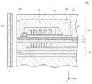
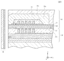
図1は、参考例の垂直磁気記録ヘッドを有する複合型磁気ヘッドを記録媒体との対向面からハイト方向(図示Y方向)と平行な方向であって且つ膜厚方向(図示Z方向)と平行な方向から切断した部分断面図、図2は実施形態の垂直磁気記録ヘッドを有する複合型磁気ヘッドを記録媒体との対向面からハイト方向(図示Y方向)と平行な方向であって且つ膜厚方向(図示Z方向)と平行な方向から切断した部分断面図、図3は参考例の垂直磁気記録ヘッドを有する複合型磁気ヘッドを記録媒体との対向面からハイト方向(図示Y方向)と平行な方向であって且つ膜厚方向(図示Z方向)と平行な方向から切断した部分断面図、図4は図1に示す垂直磁気記録ヘッドの部分平面図、図5は図2に示す垂直磁気記録ヘッドの部分平面図、図6は図1に示す垂直磁気記録ヘッドからリターンヨーク層、主磁極層及び補助ヨーク層を抜き出すとともに、記録時以外のときの磁束の流れの一例を図示した部分模式図、図7は図1に示す垂直磁気記録ヘッドからリターンヨーク層、主磁極層及び補助ヨーク層を抜き出すとともに、記録時の磁路を図示した部分模式図、図8は図2に示す垂直磁気記録ヘッドからリターンヨーク層、主磁極層及び補助ヨーク層を抜き出すとともに、記録時以外のときの磁束の流れの一例を図示した部分模式図、図9は図2に示す垂直磁気記録ヘッドからリターンヨーク層、主磁極層及び補助ヨーク層を抜き出すとともに、記録時の磁路を図示した部分模式図、図10は、図1に示す垂直磁気記録ヘッドからリターンヨーク層、主磁極層及び補助ヨーク層を抜き出すして図示した部分拡大模式図、である。 FIG. 1 shows a composite magnetic head having a perpendicular magnetic recording head of a reference example in a direction parallel to the height direction (Y direction in the drawing) and parallel to the film thickness direction (Z direction in the drawing) from the surface facing the recording medium. partial cross-sectional view taken from a direction, and the film in a direction parallel to the height direction (Y-direction) from the surface facing the recording medium composite magnetic head having a perpendicular magnetic recording head of FIG. 2 implementation form FIG. 3 is a partial cross-sectional view cut in a direction parallel to the thickness direction (Z direction in the figure). FIG. 3 shows a composite magnetic head having a perpendicular magnetic recording head of a reference example as viewed from the surface facing the recording medium in the height direction (Y direction in the figure) FIG. 4 is a partial sectional view of the perpendicular magnetic recording head shown in FIG. 1, and FIG. 5 is a vertical view shown in FIG. FIG. 6 is a partial plan view of the magnetic recording head. FIG. 7 is a partial schematic diagram illustrating an example of the flow of magnetic flux when the return yoke layer, the main magnetic pole layer, and the auxiliary yoke layer are extracted from the perpendicular magnetic recording head shown in FIG. The return yoke layer, the main magnetic pole layer, and the auxiliary yoke layer are extracted from the head, and a partial schematic diagram illustrating the magnetic path during recording. FIG. 8 shows the return yoke layer, the main magnetic pole layer, and the auxiliary magnetic head from the perpendicular magnetic recording head shown in FIG. FIG. 9 is a partial schematic view illustrating an example of the flow of magnetic flux when the yoke layer is extracted and other than during recording. FIG. 9 is a diagram illustrating the return yoke layer, the main magnetic pole layer, and the auxiliary yoke layer extracted from the perpendicular magnetic recording head shown in FIG. FIG. 10 is a partial schematic diagram illustrating the magnetic path during recording. FIG. 10 is a drawing of the return yoke layer, the main magnetic pole layer, and the auxiliary yoke layer from the perpendicular magnetic recording head shown in FIG. Partially enlarged schematic view illustrating Te is.
図中においてX方向は、トラック幅方向、Y方向は、ハイト方向、Z方向は、記録媒体の移動方向を指す。各方向は、残り2つの方向に対し直交する関係にある。X−Z平面は記録媒体との対向面H1aと平行な方向の面である。 In the drawing, the X direction indicates the track width direction, the Y direction indicates the height direction, and the Z direction indicates the moving direction of the recording medium. Each direction is orthogonal to the remaining two directions. The XZ plane is a plane parallel to the facing surface H1a facing the recording medium.
図1に示す垂直磁気記録ヘッドH1は、記録媒体Mに垂直磁界を与え、記録媒体Mのハード膜Maを垂直方向に磁化させるものである。 The perpendicular magnetic recording head H1 shown in FIG. 1 applies a perpendicular magnetic field to the recording medium M and magnetizes the hard film Ma of the recording medium M in the perpendicular direction.
記録媒体Mは例えばディスク状であり、その表面に残留磁化の高いハード膜Maが、内方に磁気透過率の高いソフト膜Mbを有しており、ディスクの中心が回転軸中心となって回転させられる。 The recording medium M has, for example, a disk shape, and has a hard film Ma having a high residual magnetization on its surface and a soft film Mb having a high magnetic permeability on its inner surface, and the center of the disk rotates around the rotation axis. Be made.
スライダ10はAl2O3・TiCなどの非磁性材料で形成されており、スライダ10の対向面10aが記録媒体Mに対向し、記録媒体Mが回転すると、表面の空気流によりスライダ10が記録媒体Mの表面から浮上し、またはスライダ10が記録媒体Mに摺動する。図1においてスライダ10に対する記録媒体Mの移動方向はA方向である。よって、A方向は空気流の方向でもある。前記空気流の上流側、すなわち図1では下方向(図示Z方向と逆方向)がリーディング側で、前記空気流の下流側、すなわち図1では上方向(図示Z方向)がトレーリング側である。
The
スライダ10のトレーリング側端面(上面)10bには、Al2O3またはSiO2などの無機材料による非磁性絶縁層12が形成されて、この非磁性絶縁層12の上に読取り部HRが形成されている。
A nonmagnetic insulating
読取り部HRは下部シールド層13と上部シールド層16と、下部シールド層13と上部シールド層16との間の無機絶縁層(ギャップ絶縁層)15内に位置する読み取り素子14とを有している。読み取り素子14は、AMR、GMR、TMRなどの磁気抵抗効果素子である。
The reading unit HR includes a
上部シールド層16の上には、コイル絶縁下地層17を介して、導電性材料で形成された複数本の下側コイル層18が形成されている。前記下側コイル層18は、例えばAu,Ag,Pt,Cu,Cr,Al,Ti,NiP,Mo,Pd,Rhから選ばれる1種、または2種以上の非磁性金属材料からなる。あるいはこれら非磁性金属材料が積層された積層構造であってもよい。
A plurality of lower coil layers 18 made of a conductive material are formed on the
下側コイル層18の周囲は、Al2O3などの無機絶縁材料や、レジストなどの有機絶縁材料で形成されたコイル絶縁層19が形成されている。
A
コイル絶縁層19の上面19aは平坦化面に形成され、この上面19aに記録媒体との対向面H1a(以下、単に対向面H1aと言う)からハイト方向(図示Y方向)に所定長さで形成され、トラック幅方向(図示X方向)への幅寸法がトラック幅Twで形成され、後端部の幅寸法がトラック幅よりも広がる主磁極層20が形成されている(図4を参照)。前記主磁極層20は、強磁性材料でメッキ形成され、Ni−Fe、Co−Fe、Ni−Fe−Coなどの飽和磁束密度の高い材料で形成されている。
An
また、主磁極層20の上面(トレーリング側端面)20eには、非磁性のスペーサ層21が形成されている。前記スペーサ層21の上面には、前記対向面H1aよりもハイト方向(図示Y方向)に後退した位置から前記ハイト方向に向けて補助ヨーク層22が形成されている。
A
前記スペーサ層21上から前記補助ヨーク層22上にかけて、コイル絶縁下地層23が形成され、前記コイル絶縁下地層23上には、導電性材料で形成された複数本の上側コイル層24が形成されている。前記上側1コイル層24は下側コイル層18と同様に、Au,Ag,Pt,Cu,Cr,Al,Ti,NiP,Mo,Pd,Rhから選ばれる1種、または2種以上の非磁性金属材料からなる。あるいはこれら非磁性金属材料が積層された積層構造であってもよい。
A coil insulating
前記下側コイル層18と上側コイル層24は、それぞれのトラック幅方向(図示X方向)における端部同士が、前記主磁極層20および補助ヨーク層22を軸にして巻回されるように電気的に接続されている。
The
上側コイル層24の周囲には、Al2O3などの無機絶縁材料や、レジストなどの有機絶縁材料で形成されたコイル絶縁層26が形成されている。
Around the upper coil layer 24, a
また、前記上側コイル層24よりも前記対向面H1a側の前記スペーサ層21上にはGd決め層27が形成されている。前記Gd決め層27は有機絶縁材料で形成されても無機絶縁材料で形成されてもどちらでもよい。前記Gd決め層27は前記対向面H1aからハイト方向(図示Y方向)に離れた位置に設けられる。前記Gd決め層27の形成は必須ではない。
Further, a Gd determining layer 27 is formed on the
図1に示すように、前記コイル絶縁層26上から前記Gd決め層27上、さらには前記Gd決め層27よりも前記対向面H1aにて露出する前記スペーサ層21上にかけてリターンヨーク層28が形成されている。前記リターンヨーク層28の前記対向面H1aからハイト方向(図示Y方向)に離れた位置にある後端部28aは、前記補助ヨーク層22の後端部22a上に接続されている。前記リターンヨーク層28の前記対向面H1a側の先端部28bは、前記主磁極層20と前記スペーサ層21を介して対向しており、前記対向面H1aでの前記スペーサ層21は前記リターンヨーク層28と主磁極層20間の磁気ギャップとして機能している。
As shown in FIG. 1, a
図1に示すように、前記リターンヨーク層28上にはAl2O3等で形成された保護層29が設けられている。
As shown in FIG. 1, a
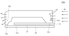
図1に示す垂直磁気記録ヘッドH1の特徴的部分について説明する。図6に示すように、前記主磁極層20の上面(トレーリング側端面)20eに、スペーサ層21を介して補助ヨーク層22が形成され、前記補助ヨーク層22の後端部22aと前記リターンヨーク層28の後端部28aとが接続されている。前記対向面H1aでは前記リターンヨーク層28の先端部28bと前記主磁極層20の先端部20aとが前記スペーサ層21を介して対向している。
A characteristic part of the perpendicular magnetic recording head H1 shown in FIG. 1 will be described. As shown in FIG. 6, an
図6に示すように、前記スペーサ層21が存在することで、記録時以外のとき、従来に比べて、前記リターンヨーク層28に効率的に吸収された外乱磁界M1は、前記スペーサ層21を挟んで構成された前記主磁極層20にまで到達できない。このように前記スペーサ層21を設けることで、前記主磁極層21と補助ヨーク層22間の磁気的な繋がりを遮断できる。
As shown in FIG. 6, the presence of the
一方、図7は、図1に示すコイル層18,24から発生した記録磁界M2が、前記リターンヨーク層28に入ると、前記記録磁界M2はまず、前記リターンヨーク層28の後端部28aと接続されている前記補助ヨーク層22に導かれる。なお図7に示す矢印は、前記記録磁界M2の流れを模式図的に示したものである。
On the other hand, FIG. 7 shows that when the recording magnetic field M2 generated from the coil layers 18 and 24 shown in FIG. 1 enters the
前記記録磁界M2の磁界強度は前記外乱磁界のそれに比べて数百倍(具体的には100倍〜200倍程度)と非常に大きい。このため前記記録磁界M2は前記補助ヨーク層22からあまり減衰することなく前記スペーサ層21を通り抜けて前記主磁極層20に到達する。すなわち記録時には、リターンヨーク層28−補助ヨーク層22−スペーサ層21―主磁極層20を通る磁路が形成されている。
The magnetic field strength of the recording magnetic field M2 is very large, several hundred times (specifically, about 100 to 200 times) that of the disturbance magnetic field. Therefore, the recording magnetic field M2 passes through the
このように、前記スペーサ層21は、記録時と記録時以外のときで、磁路に変化を与える、いわば磁路切替層として機能している。記録時以外のときは、補助ヨーク層22から主磁極層20に繋がる磁路形成を抑制し、一方、記録時には、補助ヨーク層22から主磁極層20に繋がる磁路の形成を可能とする。
Thus, the
前記スペーサ層21は非磁性であることが必要である。非磁性であれば絶縁性であっても導電性であってもどちらでもよい。前記スペーサ層21はAl2O3、SiO2、Ti、Ru、Pd、Ta、Auのうちいずれか1種あるいは2種以上の混合物により形成される。前記スペーサ層21は単層構造であってもよいし、積層構造であってもよい。
The
前記スペーサ層21の膜厚は30nm〜500nmの範囲内で形成されることが好ましい。なお前記スペーサ層21の膜厚が30nm〜80nmであれば、ギャップ層を兼ねることが出来る。これにより、記録時以外のときに、外乱磁界M1の影響が、前記補助ヨーク層22から前記主磁極層20へ到達するのを適切に抑制でき、記録時に、記録磁界M2が前記補助ヨーク層22から前記主磁極層20へあまり減衰することなく大きな磁界強度を保ちながら到達するように出来る。
The
また図4に示すように、前記補助ヨーク層22と前記主磁極層20とは、前記スペーサ層21を介して広い面積で対向している。前記主磁極層20は前記対向面H1aからハイト方向(図示Y方向)にトラック幅Twで形成された先端部20aと前記先端部20aのハイト側端部20a1,20a1からハイト方向(図示Y方向)に徐々に前記トラック幅方向(図示X方向)の幅寸法W1が広がる中間部20bと、前記中間部20bのハイト側(図示Y方向)で、トラック幅方向(図示X方向)への幅寸法がほぼ一定の幅寸法W2で形成された後端部20cとを有して構成される。なお前記主磁極層20が図4に示す平面形態に限定されるわけでない。例えば前記先端部20aの幅寸法がハイト方向に向かうにしたがって徐々に広くなるように形成されてもよいし、前記後端部20cが形成されず、前記先端部20aと中間部20bとで構成されていてもよい。図4に示す形態の主磁極層20では先端部20aの前記対向面H1aに露出する先端面20a2は、前記リターンヨーク層28の前記先端面に比べて非常に小さい面積であり、前記主磁極層20の先端部20aに記録磁界を集中させることができ、強い磁界強度の記録磁界を記録媒体Mに向けて放出できる。
As shown in FIG. 4, the
図4に示すように前記補助ヨーク層22は、前記主磁極層20の中間部20b上から後端部20c上にかけて形成されている。前記補助ヨーク層22の前記対向面H1a側の先端面22bは前記対向面H1aからハイト方向(図示Y方向)に離れた位置に形成されている。前記先端面22bはトラック幅方向の中心から、幅方向の両側に向けて徐々に、ハイト方向に後退する凸型に湾曲した形状で形成されているが、このような形状に限定されるわけでない。前記補助ヨーク層22は前記先端面22bよりもハイト方向(図示Y方向)の領域では、トラック幅方向(図示X方向)の幅寸法がほぼ一定の幅寸法W3で形成されているがこのような形状に限定されるわけではない。また前記補助ヨーク層22の前記幅寸法W3が、前記主磁極層20の後端部20cの幅寸法W2より小さく形成されているが、前記幅寸法W3が、前記幅寸法W2より大きく形成されても同じ寸法で形成されてもよい。
As shown in FIG. 4, the
ところで、前記補助ヨーク層22が形成されていない形態も本実施の形態である。かかる場合、前記主磁極層20は、前記リターンヨーク層28の後端部28aに前記スペーサ層21を介して対向するため、前記主磁極層20は前記リターンヨーク層28の後端部28aから記録磁界M2を受けるが、前記後端部28aの前記主磁極層20に対する対向面積は図4に示す点線箇所だけであるから対向面積が小さく、スペーサ層21を設けたことによる記録磁界M2の磁界強度の減衰が大きくなりやすい。
Incidentally, the embodiment in which the
一方、図1及び図4に示す形態では、前記リターンヨーク層28の後端部28aに前記補助ヨーク層22を接続させているため、記録磁界M2は前記リターンヨーク層28から前記補助ヨーク層22に導かれるが、前記補助ヨーク層22と前記主磁極層20との対向面積は非常に広いため、記録磁界が、広い範囲にわたって、前記補助ヨーク層22から前記主磁極層20へ流れ込むので、前記スペーサ層21を設けたことによって記録磁界が減衰するのをより適切に抑制でき、良好な記録特性を維持することが出来る。
On the other hand, in the form state shown in FIGS. 1 and 4, since the said to connect the
ここで図1に示す本形態の具体的な構成を挙げる。前記主磁極層20はFe80Co5Ni15で形成され、膜厚が300nmで形成される。前記スペーサ層21はAl2O3で形成され、膜厚が50nmで形成される。前記補助ヨーク層22は、Ni81Fe19で形成され、膜厚が300nmで形成される。また前記主磁極層20および補助ヨーク層22は幅寸法が10μm以下の範囲内で形成される。また記録磁界M2の磁界強度は、例えば磁極先端で概ね10kOe(=約790kA/m)であり、外乱磁界M1の磁界強度は例えば、0〜200Oe程度(約0〜15800A/m)である。
Here mention a specific configuration of the shaped state shown in FIG. The main
図1に示す形態では前記スペーサ層21は、補助ヨーク層22と主磁極層20の間のみならず前記前記対向面H1a側で前記リターンヨーク層28の先端部28bと前記主磁極層20間にも介在している。そして前記スペーサ層21は前記対向面H1aで磁気ギャップとして機能している。図1に示す形態では、前記スペーサ層21に前記磁気ギャップとしての機能を持たせ、前記スペーサ層21とは別個に磁気ギャップ層を設ける必要性がないので、記録特性に優れるとともに外乱磁界の悪影響を抑制できる垂直磁気記録ヘッドを簡単な構造で形成できる。
The
ところで図1に示す形態では、前記スペーサ層21は、磁気ギャップの箇所でも、他の箇所でも同じ膜厚で形成されているが、同じ膜厚で形成されていなくてもよい。
Meanwhile in the form state shown in FIG. 1, the
図10に示すように、前記補助ヨーク層22と前記主磁極層20間に介在するスペーサ層21の膜厚はH4で形成され、一方、前記リターンヨーク層28の先端部28bと前記主磁極層20間に介在する、ちょうど磁気ギャップとなる部分での前記スペーサ層21の膜厚はH5で形成されている。そして前記スペーサ層21の膜厚H4と膜厚H5は同じ寸法であってもよいし、異なる寸法であってもよい。異なる寸法の場合、前記磁気ギャップとなる箇所の前記スペーサ層21の膜厚H5のほうが、前記補助ヨーク層22と前記主磁極層20間に介在するスペーサ層21の膜厚H4よりも小さいことが好ましい。記録時に、磁気ギャップの部分で、主磁極層20とリターンヨーク層28を近接させることで、垂直記録磁界の磁界分布を最適化し、記録媒体Mに効率的な信号記録が可能になる。また、前記スペーサ層21の膜厚H4が前記膜厚H5よりも薄いと、前記補助ヨーク層22と主磁極層21の磁気的分離が不十分になり、外乱磁界の悪影響を適切に抑制することが困難になる。
As shown in FIG. 10, the
また前記主磁極層20と前記補助ヨーク層22間に介在する前記スペーサ層21の膜厚H4は、前記補助ヨーク層22の後端部22a上に前記リターンヨーク層28をメッキ形成する際に必要なメッキ下地層に含まれる非磁性層(以下、非磁性メッキ下地層と呼ぶ)40の膜厚よりも厚く形成されている。前記非磁性メッキ下地層40は非常に薄いために(具体的には5nm)、外乱磁界を通してしまい前記外乱磁界を遮断する役割を担っていない。一方、本実施形態のスペーサ層21は前記非磁性メッキ下地層40より厚い膜厚で形成され、前記外乱磁界を遮断する役割を担っている。なお前記スペーサ層21の膜厚H4の大きさを、前記補助ヨーク層22の後端部22aとリターンヨーク層28の後端部28a間の非磁性メッキ下地層40の膜厚と比較して説明したが、比較対象となる非磁性メッキ下地層は、磁性層どうしが非磁性メッキ下地層を介して接続され、外乱磁界及び記録磁界に対する磁路を形成する箇所での前記非磁性メッキ下地層であれば特に限定しない。非磁性メッキ下地層は、どの部位においても大差なく非常に薄い膜厚である。あるいはメッキ下地層は非磁性でなく磁性層で形成される場合もある(かかる場合は、非磁性メッキ下地層の膜厚は0である)。例えば次に説明する図2であれば、薄膜磁性層30と補助ヨーク層22間の非磁性メッキ下地層、前記補助ヨーク層22とリターンヨーク層28の後端部28a間の非磁性メッキ下地層が該当する。
The thickness H4 of the
また本形態において、前記スペーサ層21が前記補助ヨーク層22をメッキ形成する際のメッキ下地として使用されることを除外するものではない。
Also in this form state, it does not exclude that the
図2に示す実施形態の垂直磁気記録ヘッドH2では、図1と異なり、前記補助ヨーク層22の下面(リーディング側端面)22cに、前記主磁極層20より薄い膜厚の薄膜磁性層30が接続されている。前記薄膜磁性層30は前記リターンヨーク層28の先端部28bの下面にも接続されている。前記薄膜磁性層30の下側には非磁性の前記スペーサ層21を介して主磁極層20が形成されている。
In the perpendicular magnetic recording head H2 of the implementation form shown in FIG. 2, unlike FIG. 1, the lower surface (the leading end face) 22c of the
前記薄膜磁性層30は前記主磁極層20に比べて飽和磁束密度の小さい磁性材料で形成されることが好ましい。また前記薄膜磁性層30は前記主磁極層20に比べて透磁率が大きい磁性材料で形成されることがより好ましい。前記薄膜磁性層30はNi81Fe19、Co70Fe20Ni10のうちいずれか1種あるいは2種以上の混合物により形成される。前記薄膜磁性層30は単層構造でも積層構造でもどちらでもよい。
The thin film
上記したように、前記薄膜磁性層30は前記主磁極層20より薄い膜厚で形成されるが、具体的には10nm(5〜20nm程度の範囲内)で形成されることが好ましい。
As described above, the thin film
前記薄膜磁性層30は前記補助ヨーク層22及びリターンヨーク層28間を接続しており、記録時以外のとき、リターンヨーク層28、補助ヨーク層22及び薄膜磁性層30に至る閉磁路が形成される。図8に示すように外乱磁界M3が前記リターンヨーク層28に吸収されると前記外乱磁界M3はリターンヨーク層28−補助ヨーク層22−薄膜磁性層30で構成される磁性構造体に効率よく吸収されるため、前記外乱磁界M3の影響が、前記スペーサ層21を介して、主磁極層20により到達しにくくなる。
The thin film
前記薄膜磁性層30は、前記主磁極層20に比べて薄い膜厚で、さらに好ましくは飽和磁束密度が低く透磁率が高い磁性材料で形成されているので、外乱磁界に対し数百倍大きい磁界強度を有する記録磁界がリターンヨーク層28から前記補助ヨーク層22を介して前記薄膜磁性層30へ導かれると、前記薄膜磁性層30は磁気飽和に達する。前記薄膜磁性層30が磁気飽和に達すると、図9に示すように前記記録磁界M4が前記薄膜磁性層30からスペーサ層21を介して前記主磁極層20にまで導かれる。
The thin film
前記薄膜磁性層30は、スペーサ層21とともに、記録時と記録時以外のときとで、磁路に変化を与える、いわば磁路切替層として機能している。記録時以外のとき、前記薄膜磁性層30は磁気飽和に達しないため、外乱磁界M3に対する閉磁路の形成を可能にし、一方、記録時、前記薄膜磁性層30は磁気飽和に達し、補助ヨーク層22から主磁極層20に繋がる磁路の形成を可能にしている。なお仮に、前記薄膜磁性層30が、記録時以外のとき、外乱磁界M3によって磁気飽和に達しても、前記スペーサ層21を設けた効果によって、前記記録磁界M4に比べて非常に弱い外乱磁界M3が前記スペーサ層21を介して主磁極層20に到達するのを抑制できるので、外乱磁界による悪影響を従来よりも低減できる。
The thin film
図5に示すように、前記薄膜磁性層30は前記主磁極層20よりも一回り小さい平面形状で形成されているが、このような形状に限定されるものではない。前記薄膜磁性層30は前記主磁極層20より大きい平面形状で形成されてもよい。また前記薄膜磁性層30は主磁極層20と同様に、トラック幅方向(図示X方向)への幅寸法W4が細い先端部30a、幅寸法W5がハイト方向に向かうほど徐々に大きくなる中間部30b、及び前記中間部30bのハイト側(図示Y方向)にあり、トラック幅方向(図示X方向)への幅寸法がほぼ一定の幅寸法W6で形成された後端部30cで構成されているが、このような構成に限定されるものではない。また前記先端部30aの前記対向面H1aに向く先端面30a1は前記対向面H1aと一致しているが前記先端面30a1が前記対向面H1aからハイト方向(図示Y方向)に、リターンヨーク層28の先端部28bの下面と接続される範囲において、若干後退していてもよい。なおこのように前記薄膜磁性層30の先端面30a1を前記ハイト方向(図示Y方向)に少しでも後退させたほうが、前記薄膜磁性層30から記録媒体Mに予期せぬ磁界が放出される可能性を低減できて好ましい。
As shown in FIG. 5, the thin film
前記薄膜磁性層30の平面形状があまり大きく形成されると、磁界強度が強い記録磁界M4を受けても前記薄膜磁性層30が効果的に磁気飽和しにくくなる。よって前記薄膜磁性層30を、前記主磁極層20と同程度の平面形状で形成するか、前記主磁極層20の平面形状より小さく形成することが好ましい。
If the planar shape of the thin film
ここで図2に示す本実施形態の具体的な構成を挙げる。前記主磁極層20はFe80Co5Ni15で形成され、膜厚が300nmで形成される。前記スペーサ層21はAl2O3で形成され、膜厚が50nmで形成される。前記補助ヨーク層22は、Ni81Fe19で形成され、膜厚が300nmで形成される。また前記主磁極層20および補助ヨーク層22は幅寸法が10μm以下の範囲内で形成される。また記録磁界M4の磁界強度は、例えば磁極先端で概ね10kOe(=約790kA/m)であり、外乱磁界M3の磁界強度は例えば、0〜200Oe程度(約0〜15800A/m)である。また、前記薄膜磁性層30は、Ni81Fe19で形成され、膜厚が10nmで形成される。また前記薄膜磁性層30は幅方向(図示X方向)への寸法が10μm、ハイト方向(図示Y方向)への寸法が20μmの四方内に収まる程度の平面形状で形成される。
Here, a specific configuration of the present embodiment shown in FIG. 2 will be given. The main
図3に示す形態の垂直磁気記録ヘッドH3は、主磁極層20の下面(リーディング側端面)に、補助ヨーク層22が形成され、前記主磁極層20の上面(トレーリング側端面)20eにスペーサ層21が形成されている。図3に示す形態では、リターンヨーク層28の後端部28aと前記主磁極層20の後端部20cとの間に、前記スペーサ層21のみが介在し、図1,図2の形態のように補助ヨーク層22は介在しない。このため、記録時、前記主磁極層20は前記後端部28aから記録磁界を受けるが、前記リターンヨーク層28の後端部28aの前記主磁極層20に対する対向面積は図4に示す点線箇所だけであるから前記対向面積が小さく、スペーサ層21を設けたことによる記録磁界の減衰が図1や図2に示す形態に比べて大きくなりやすいと考えられる。
The perpendicular magnetic recording head H3 of the shape state shown in FIG. 3, the lower surface of the main magnetic pole layer 20 (the leading end face), the
また図1,図2のように、主磁極層20の上に補助ヨーク層22を設けた形態であると、前記リターンヨーク層28の先端部28bの後ろに(ハイト側に)前記補助ヨーク層22を設けることができ、図3と比べて、前記下側コイル層18と上側コイル層24間の接続を容易にすることができ、ひいては前記下側コイル層18及び上側コイル層24を有して成るコイル全体のコイル長を短く出来るので、コイル抵抗を低減できる。
As shown in FIGS. 1 and 2, when the
ただし図3に示す形態でも、記録時以外のとき、前記リターンヨーク層28に吸収された外乱磁界が、前記スペーサ層21を介して、前記主磁極層20に入り込まず、前記外乱磁界による記録信号の消去等の悪影響を従来に比べて抑制することが可能である。
However, in the form state shown in FIG. 3, when other than the recording, a disturbance magnetic field absorbed by the
なお図3の形態の場合、前記スペーサ層21の形成位置は、少なくとも前記リターンヨーク層28と前記主磁極層20との後端部間に介在していればよい。また図1や図2のように主磁極層20とリターンヨーク層28との間に補助ヨーク層22が介在する構成では、前記スペーサ層21は少なくとも前記補助ヨーク層22と主磁極層20との間に設けられていればよい。
In the case of the embodiment of FIG. 3, the
また補助ヨーク層22は特に必須の層ではない。例えば図1や図2の形態において前記補助ヨーク層22が形成されていない形態でもよい。しかし補助ヨーク層22を設けたほうが前記主磁極層20と対向する磁性層領域が大きくなり、広範囲にわたって前記主磁極層20に記録磁界を供給できるため、良好な記録特性の維持の観点からは前期補助ヨーク層22を設ける必要がある。
Further, the
20 主磁極層
21 スペーサ層
22 補助ヨーク層
28 リターンヨーク層
30 薄膜磁性層
40 非磁性メッキ下地層
20
Claims (4)
少なくとも、前記主磁極層及びリターンヨーク層の前記対向面からハイト方向に離れた後端部間には非磁性のスペーサ層が設けられ、
前記主磁極層より膜厚の薄い磁性材料製の薄膜磁性層が、前記リターンヨーク層と前記対向面及び前記後端部で接続されており、前記薄膜磁性層と前記主磁極層との間に、前記スペーサ層が設けられることを特徴とする垂直磁気記録ヘッド。 A main pole layer made of a magnetic material, and a return yoke layer made of a magnetic material facing the main pole layer across a nonmagnetic gap layer on the trailing side of the main pole layer on the surface facing the recording medium A coil layer for applying a recording magnetic field to the main magnetic pole layer and the return yoke layer,
At least a nonmagnetic spacer layer is provided between the rear end portions of the main magnetic pole layer and the return yoke layer that are separated from each other in the height direction .
A thin film magnetic layer made of a magnetic material having a thickness smaller than that of the main magnetic pole layer is connected to the return yoke layer at the opposing surface and the rear end, and between the thin film magnetic layer and the main magnetic pole layer. , perpendicular magnetic recording head, wherein said spacer layer is provided.
前記補助ヨーク層と前記スペーサ層間に前記薄膜磁性層が設けられ、前記薄膜磁性層は、前記リターンヨーク層の対向面と接続されるとともに、前記補助ヨークの後端部と接続されている請求項1記載の垂直磁気記録ヘッド。 An auxiliary yoke layer is provided between the main magnetic pole layer and the return yoke layer, and a rear end portion of the auxiliary yoke is connected to a rear end portion of the return yoke layer;
The thin film magnetic layer is provided between the auxiliary yoke layer and the spacer layer, and the thin film magnetic layer is connected to a facing surface of the return yoke layer and to a rear end portion of the auxiliary yoke. 1. A perpendicular magnetic recording head according to 1.
Priority Applications (2)
| Application Number | Priority Date | Filing Date | Title |
|---|---|---|---|
| JP2005206691A JP4032062B2 (en) | 2005-07-15 | 2005-07-15 | Perpendicular magnetic recording head |
| US11/485,815 US7593185B2 (en) | 2005-07-15 | 2006-07-13 | Perpendicular magnetic recording head having spacer layer in predetermined portion |
Applications Claiming Priority (1)
| Application Number | Priority Date | Filing Date | Title |
|---|---|---|---|
| JP2005206691A JP4032062B2 (en) | 2005-07-15 | 2005-07-15 | Perpendicular magnetic recording head |
Publications (2)
| Publication Number | Publication Date |
|---|---|
| JP2007026534A JP2007026534A (en) | 2007-02-01 |
| JP4032062B2 true JP4032062B2 (en) | 2008-01-16 |
Family
ID=37661446
Family Applications (1)
| Application Number | Title | Priority Date | Filing Date |
|---|---|---|---|
| JP2005206691A Expired - Fee Related JP4032062B2 (en) | 2005-07-15 | 2005-07-15 | Perpendicular magnetic recording head |
Country Status (2)
| Country | Link |
|---|---|
| US (1) | US7593185B2 (en) |
| JP (1) | JP4032062B2 (en) |
Families Citing this family (24)
| Publication number | Priority date | Publication date | Assignee | Title |
|---|---|---|---|---|
| JP4867698B2 (en) * | 2007-02-20 | 2012-02-01 | Tdk株式会社 | Thin film magnetic device and electronic component module having the same |
| JP2008277586A (en) * | 2007-04-27 | 2008-11-13 | Toshiba Corp | Magnetic element, magnetic recording head and magnetic recording apparatus |
| KR20080108016A (en) * | 2007-06-07 | 2008-12-11 | 가부시끼가이샤 도시바 | Magnetic recording head and magnetic recording device |
| US8994587B2 (en) | 2010-05-14 | 2015-03-31 | Qualcomm Incorporated | Compressed sensing for navigation data |
| JP4358279B2 (en) * | 2007-08-22 | 2009-11-04 | 株式会社東芝 | Magnetic recording head and magnetic recording apparatus |
| JP4919901B2 (en) * | 2007-09-04 | 2012-04-18 | 株式会社東芝 | Magnetic recording head and magnetic recording apparatus |
| JP2009070439A (en) * | 2007-09-11 | 2009-04-02 | Toshiba Corp | Magnetic recording head and magnetic recording device |
| JP4929108B2 (en) * | 2007-09-25 | 2012-05-09 | 株式会社東芝 | Magnetic head and magnetic recording apparatus |
| JP2009080875A (en) | 2007-09-25 | 2009-04-16 | Toshiba Corp | Magnetic head and magnetic recording system |
| JP2009080878A (en) * | 2007-09-25 | 2009-04-16 | Toshiba Corp | Magnetic recording head and magnetic recording device |
| US8056213B2 (en) * | 2007-10-03 | 2011-11-15 | Headway Technologies, Inc. | Method to make PMR head with integrated side shield (ISS) |
| US8111479B2 (en) * | 2007-10-23 | 2012-02-07 | Hitachi Global Storage Technologies Netherlands B.V. | Perpendicular magnetic recording head having a notched trailing shield |
| US7889456B2 (en) * | 2007-11-13 | 2011-02-15 | Hitachi Global Storage Technologies Netherlands B.V. | Perpendicular magnetic recording write head with flux shaping layers on the write pole and magnetic recording system incorporating the write head |
| JP5377893B2 (en) * | 2008-06-19 | 2013-12-25 | 株式会社東芝 | Magnetic head assembly and magnetic recording / reproducing apparatus |
| JP2010003353A (en) | 2008-06-19 | 2010-01-07 | Toshiba Corp | Magnetic recording head, magnetic head assembly, and magnetic recorder |
| JP5361259B2 (en) | 2008-06-19 | 2013-12-04 | 株式会社東芝 | Spin torque oscillator, magnetic recording head, magnetic head assembly, and magnetic recording apparatus |
| JP2010040126A (en) | 2008-08-06 | 2010-02-18 | Toshiba Corp | Magnetic recording head, magnetic head assembly, and magnetic recording device |
| JP5320009B2 (en) * | 2008-10-06 | 2013-10-23 | 株式会社東芝 | Spin torque oscillator, magnetic recording head, magnetic head assembly, and magnetic recording apparatus |
| JP5173750B2 (en) * | 2008-11-06 | 2013-04-03 | 株式会社東芝 | Spin torque oscillator, magnetic recording head, magnetic head assembly, and magnetic recording apparatus |
| JP5558698B2 (en) | 2008-11-28 | 2014-07-23 | 株式会社東芝 | Magnetic recording head, magnetic head assembly, magnetic recording apparatus, and magnetic recording method |
| JP2010146641A (en) * | 2008-12-19 | 2010-07-01 | Hitachi Global Storage Technologies Netherlands Bv | Perpendicular recording magnetic head, manufacturing method thereof, and magnetic disk device |
| US8441757B2 (en) * | 2009-12-09 | 2013-05-14 | HGST Netherlands B.V. | Perpendicular magnetic write head with wrap-around shield, slanted pole and slanted pole bump fabricated by damascene process |
| JP5606482B2 (en) | 2012-03-26 | 2014-10-15 | 株式会社東芝 | Magnetic head, magnetic head assembly, magnetic recording / reproducing apparatus, and magnetic head manufacturing method |
| US9838823B2 (en) * | 2013-04-27 | 2017-12-05 | Intellectual Discovery Co., Ltd. | Audio signal processing method |
Family Cites Families (8)
| Publication number | Priority date | Publication date | Assignee | Title |
|---|---|---|---|---|
| US6285528B1 (en) * | 1993-03-15 | 2001-09-04 | Kabushiki Kaisha Toshiba | Thin-film magnetic head |
| JP3368247B2 (en) | 2000-03-06 | 2003-01-20 | 秋田県 | Thin-film single-pole magnetic recording head |
| JP3593312B2 (en) * | 2000-12-26 | 2004-11-24 | アルプス電気株式会社 | Perpendicular magnetic recording head and method of manufacturing the same |
| JP3950725B2 (en) | 2002-04-05 | 2007-08-01 | 新科實業有限公司 | Thin film magnetic head, method of manufacturing the same, and magnetic recording apparatus |
| US6791796B2 (en) * | 2002-05-28 | 2004-09-14 | Seagate Technology Llc | Perpendicular writer with laminated main pole |
| US7038882B2 (en) * | 2002-10-03 | 2006-05-02 | Seagate Technology | Low moment-high moment write pole with non-magnetic layer for establishing a magnetic path discontinuity between layers of the write pole |
| JP3774446B2 (en) * | 2003-04-28 | 2006-05-17 | 株式会社東芝 | Perpendicular magnetic recording head and magnetic disk apparatus |
| JP4099131B2 (en) | 2003-09-24 | 2008-06-11 | 秋田県 | Thin-film single-pole magnetic head |
-
2005
- 2005-07-15 JP JP2005206691A patent/JP4032062B2/en not_active Expired - Fee Related
-
2006
- 2006-07-13 US US11/485,815 patent/US7593185B2/en not_active Expired - Fee Related
Also Published As
| Publication number | Publication date |
|---|---|
| US20070014049A1 (en) | 2007-01-18 |
| US7593185B2 (en) | 2009-09-22 |
| JP2007026534A (en) | 2007-02-01 |
Similar Documents
| Publication | Publication Date | Title |
|---|---|---|
| JP4032062B2 (en) | Perpendicular magnetic recording head | |
| US7643246B2 (en) | Perpendicular magnetic recording head having a stepped portion and method of manufacturing the same | |
| JP5571625B2 (en) | Magnetic head for perpendicular magnetic recording having a shield provided around the main pole | |
| US7859791B2 (en) | Perpendicular magnetic recording head having a main magnetic pole layer with a trapezoidally shaped flared part with a ratio of the length of the long base to that of the short base is equal to 1 | |
| US7609478B2 (en) | Magnetic writer pole with a graded magnetic moment | |
| US20100321825A1 (en) | Magnetic writer with multi-component shielf | |
| US8243386B2 (en) | Perpendicular magnetic recording head with bottom shield layer | |
| JP2012123888A (en) | Magnetic head for perpendicular magnetic recording having shield provided around main pole | |
| JP5826987B2 (en) | Magnetic head slider | |
| US7889457B2 (en) | Perpendicular magnetic recording head device capable of increasing magnetic field gradient to exhibit excellent recording performance while maintaining magnetic field intensity | |
| JP2006012378A (en) | Magnetic head for perpendicular magnetic recording and method of manufacturing the same | |
| US7990654B2 (en) | Perpendicular magnetic recording head | |
| JP2006018927A (en) | Magnetic head and magnetic recording and reproducing device mounting same | |
| JP2007220261A (en) | Thin film magnetic head | |
| US7545603B2 (en) | Magnetic head and manufacturing method thereof | |
| US7692896B2 (en) | Perpendicular magnetic recording head having return path layer and gap adjusting layer | |
| JP2006252694A (en) | Magnetic head for vertical recording | |
| US8817417B2 (en) | Perpendicular magnetic write head and magnetic recording device | |
| JP2006252697A (en) | Perpendicular magnetic recording element, thin film magnetic head, magnetic head device, and magnetic recording/reproducing device | |
| JP4044922B2 (en) | Magnetic recording head | |
| JP2004348928A (en) | Perpendicular recording magnetic head | |
| US7843667B2 (en) | Thin film magnetic head, head gimbal assembly, head arm assembly and magnetic disk device | |
| JP2008276902A (en) | Perpendicular magnetic recording head | |
| JP3902183B2 (en) | Magnetic head, manufacturing method thereof, and magnetic recording / reproducing apparatus | |
| JP2006277905A (en) | Magnetic head for vertical recording and magnetic storage device |
Legal Events
| Date | Code | Title | Description |
|---|---|---|---|
| A977 | Report on retrieval |
Free format text: JAPANESE INTERMEDIATE CODE: A971007 Effective date: 20070702 |
|
| A131 | Notification of reasons for refusal |
Free format text: JAPANESE INTERMEDIATE CODE: A131 Effective date: 20070710 |
|
| A521 | Written amendment |
Free format text: JAPANESE INTERMEDIATE CODE: A523 Effective date: 20070817 |
|
| TRDD | Decision of grant or rejection written | ||
| A01 | Written decision to grant a patent or to grant a registration (utility model) |
Free format text: JAPANESE INTERMEDIATE CODE: A01 Effective date: 20071016 |
|
| A61 | First payment of annual fees (during grant procedure) |
Free format text: JAPANESE INTERMEDIATE CODE: A61 Effective date: 20071022 |
|
| R150 | Certificate of patent or registration of utility model |
Free format text: JAPANESE INTERMEDIATE CODE: R150 |
|
| FPAY | Renewal fee payment (event date is renewal date of database) |
Free format text: PAYMENT UNTIL: 20101026 Year of fee payment: 3 |
|
| FPAY | Renewal fee payment (event date is renewal date of database) |
Free format text: PAYMENT UNTIL: 20101026 Year of fee payment: 3 |
|
| S111 | Request for change of ownership or part of ownership |
Free format text: JAPANESE INTERMEDIATE CODE: R313113 |
|
| FPAY | Renewal fee payment (event date is renewal date of database) |
Free format text: PAYMENT UNTIL: 20101026 Year of fee payment: 3 |
|
| R350 | Written notification of registration of transfer |
Free format text: JAPANESE INTERMEDIATE CODE: R350 |
|
| FPAY | Renewal fee payment (event date is renewal date of database) |
Free format text: PAYMENT UNTIL: 20111026 Year of fee payment: 4 |
|
| FPAY | Renewal fee payment (event date is renewal date of database) |
Free format text: PAYMENT UNTIL: 20121026 Year of fee payment: 5 |
|
| LAPS | Cancellation because of no payment of annual fees |