JP5353530B2 - Image forming apparatus - Google Patents
Image forming apparatus Download PDFInfo
- Publication number
- JP5353530B2 JP5353530B2 JP2009176067A JP2009176067A JP5353530B2 JP 5353530 B2 JP5353530 B2 JP 5353530B2 JP 2009176067 A JP2009176067 A JP 2009176067A JP 2009176067 A JP2009176067 A JP 2009176067A JP 5353530 B2 JP5353530 B2 JP 5353530B2
- Authority
- JP
- Japan
- Prior art keywords
- wiper
- head
- cleaner
- wiper blade
- cleaning
- Prior art date
- Legal status (The legal status is an assumption and is not a legal conclusion. Google has not performed a legal analysis and makes no representation as to the accuracy of the status listed.)
- Active
Links
Images


Landscapes
- Ink Jet (AREA)
Abstract
Description
本発明は画像形成装置に関し、特に液滴を吐出する記録ヘッドを備える画像形成装置に関する。 The present invention relates to an image forming apparatus, and more particularly to an image forming apparatus provided with a recording head for discharging droplets.
プリンタ、ファクシミリ、複写装置、プロッタ、これらの複合機等の画像形成装置として、例えばインク液滴を吐出する記録ヘッドを用いた液体吐出記録方式の画像形成装置としてインクジェット記録装置などが知られている。この液体吐出記録方式の画像形成装置は、記録ヘッドからインク滴を、搬送される用紙に対して吐出して、画像形成(記録、印字、印写、印刷も同義語で使用する。)を行なうものであり、記録ヘッドが主走査方向に移動しながら液滴を吐出して画像を形成するシリアル型画像形成装置と、記録ヘッドが移動しない状態で液滴を吐出して画像を形成するライン型ヘッドを用いるライン型画像形成装置がある。 As an image forming apparatus such as a printer, a facsimile machine, a copying apparatus, a plotter, and a complex machine of these, for example, an ink jet recording apparatus is known as an image forming apparatus of a liquid discharge recording method using a recording head for discharging ink droplets. . This liquid discharge recording type image forming apparatus ejects ink droplets from a recording head onto a conveyed paper to form an image (recording, printing, printing, and printing are also used synonymously). Serial type image forming device that forms an image by ejecting droplets while the recording head moves in the main scanning direction, and a line type that forms images by ejecting droplets without the recording head moving There is a line type image forming apparatus using a head.
なお、本願において、液体吐出記録方式の「画像形成装置」は、紙、糸、繊維、布帛、皮革、金属、プラスチック、ガラス、木材、セラミックス等の媒体にインクを着弾させて画像形成を行う装置を意味し、また、「画像形成」とは、文字や図形等の意味を持つ画像を媒体に対して付与することだけでなく、パターン等の意味を持たない画像を媒体に付与すること(単に液滴を媒体に着弾させること)をも意味する。また、「インク」とは、インクと称されるものに限らず、記録液、定着処理液、樹脂、液体などと称されるものなど、画像形成を行うことができるすべての液体の総称として用いる。また、「用紙」とは、材質を紙に限定するものではなく、上述したOHPシート、布なども含み、インク滴が付着されるものの意味であり、被記録媒体、記録媒体、記録紙、記録用紙などと称されるものを含むものの総称として用いる。また、画像とは2次元画像に限らず、3次元画像も含まれる。 In the present application, the “image forming apparatus” of the liquid discharge recording method is an apparatus that forms an image by landing ink on a medium such as paper, thread, fiber, fabric, leather, metal, plastic, glass, wood, ceramics or the like. In addition, “image formation” means not only giving an image having a meaning such as a character or a figure to a medium but also giving an image having no meaning such as a pattern to the medium (simply It also means that a droplet is landed on a medium). The term “ink” is not limited to what is referred to as ink, but is used as a general term for all liquids that can perform image formation, such as recording liquid, fixing processing liquid, resin, and liquid. . The term “paper” is not limited to paper, but includes the above-described OHP sheet, cloth, and the like, and means that ink droplets adhere to the recording medium, recording medium, recording paper, recording It is used as a general term for what includes what is called paper. Further, the image is not limited to a two-dimensional image, and includes a three-dimensional image.
このような画像形成装置(以下、単に「インクジェット記録装置」ともいう。)においては、記録ヘッドは、インクをノズルから用紙に吐出させて記録を行なう関係上、ノズルからの溶媒の蒸発に起因するインク粘度の上昇や、インクの固化、塵埃の付着、さらには気泡の混入などにより吐出不良の状態となり、記録不良を起こすという問題を抱えていることから、記録ヘッドの性能を維持回復する維持回復機構を備えている。 In such an image forming apparatus (hereinafter, also simply referred to as “inkjet recording apparatus”), the recording head is caused by the evaporation of the solvent from the nozzle because of recording by discharging ink from the nozzle onto the paper. Maintenance and recovery to maintain and recover the performance of the print head due to problems such as increased ink viscosity, ink solidification, dust adhesion, and bubble failure due to air bubbles. It has a mechanism.
例えば、記録ヘッドのノズルを密封するキャップ(キャッピング手段、キャップ部材などとも称する。)を備え、装置の非稼動時には記録ヘッドのキャッピングを行うことで、ノズル内のインクの乾燥、増粘を抑えることができるようにしている。また、記録動作の前後やその最中において、記録動作に寄与しないインク滴の吐出を行い、ノズル内で乾燥、増粘したインクを排出して、吐出性能の回復や維持を図るようにしている。 For example, a cap (also referred to as a capping unit or a cap member) that seals the nozzles of the recording head is provided, and capping of the recording head is performed when the apparatus is not in operation, thereby suppressing drying and thickening of ink in the nozzles. To be able to. In addition, before and after the recording operation and during the recording operation, ink droplets that do not contribute to the recording operation are discharged, and the ink dried and thickened in the nozzles is discharged so that the discharge performance can be recovered and maintained. .
このようなノズルの吐出性維持のための画像形成に寄与しないインク滴の吐出は予備吐出或いは空吐出と称され、専用の空吐出受けに吐出し、あるいは、キャップに対して吐出することが行われる。 The ejection of ink droplets that do not contribute to image formation for maintaining the ejection performance of the nozzles is called preliminary ejection or idle ejection, and can be ejected to a dedicated idle ejection receiver or ejected to a cap. Is called.
そして、維持回復動作を行うときには、インク排出後、記録ヘッドのノズル面をワイパ部材(ワイパーブレード、ワイピング手段などとも称する。)で払拭(ワイピング)してノズルメニスカスを正常な状態に戻すようにしている。 When the maintenance and recovery operation is performed, after the ink is discharged, the nozzle surface of the recording head is wiped with a wiper member (also referred to as a wiper blade or a wiping unit) to return the nozzle meniscus to a normal state. Yes.
この場合、ワイパ部材に転移付着したインクの廃液を除去してワイパ部材を清浄化するワイパ清掃手段(ワイパクリーナ)を備えるものが知られている。例えば、ワイパ部材の側面及び天面の廃液を除去するための掻き取りブレード、掻き取りマイラなどの掻き落し手段を備えるものがある(特許文献1)。 In this case, there is known one provided with wiper cleaning means (wiper cleaner) for removing the waste liquid of the ink transferred and adhered to the wiper member to clean the wiper member. For example, there is one provided with scraping means such as a scraping blade and scraping mylar for removing waste liquid on the side surface and top surface of the wiper member (Patent Document 1).
しかしながら、上述したワイパ清掃手段にあっては、ワイパ部材に対して掻き取り手段を均一に接触させることが難しく、接触が不均一になると、掻き取り不良が発生することになる。また、掻き取り手段で掻き取った廃液を更に掻き落し手段で掻き取り、掻き落し手段に付着した廃液を更にマイラなどで掻き取るなど、ワイパ清掃手段を構成する各部材の清掃が必要になる。 However, in the above-described wiper cleaning means, it is difficult to make the scraping means uniformly contact with the wiper member, and if the contact becomes uneven, scraping failure occurs. Further, it is necessary to clean each member constituting the wiper cleaning means, for example, the waste liquid scraped off by the scraping means is further scraped off by the scraping means, and the waste liquid adhering to the scraping means is further scraped off by a mylar.
本発明は上記の課題に鑑みてなされたものであり、簡単な構成でワイパ部材を清掃できるようにすることを目的とする。 The present invention has been made in view of the above problems, and an object thereof is to enable the wiper member to be cleaned with a simple configuration.
上記の課題を解決するため、本発明に係る画像形成装置は、
液滴を吐出するノズルを有する記録ヘッドと、
前記記録ヘッドのノズル面を払拭するブレード状のワイパ部材と、
前記ワイパ部材に付着した廃液を除去するワイパ清掃手段と、を備え、
前記ワイパ清掃手段は、
連続する1枚のウエブを有し、
前記ウエブにより、前記ワイパ部材の天面及び払拭面を同時に挟み込んで、前記ワイパ部材の天面及び払拭面に付着した廃液を除去する
構成とした。
In order to solve the above problems, an image forming apparatus according to the present invention provides:
A recording head having nozzles for discharging droplets;
A blade-like wiper member for wiping the nozzle surface of the recording head;
Wiper cleaning means for removing waste liquid adhering to the wiper member,
The wiper cleaning means includes
Having one continuous web,
By the web, crowded viewed nip simultaneously the top and the wiping surface of the wiper member, and configured to remove the waste liquid adhering to the top and the wiping surface of the wiper member.
本発明に係る画像形成装置によれば、簡単な構成でワイパ部材を確実に清掃することができる。 According to the image forming apparatus according to the present invention, it is possible to reliably clean the wiper member in easy single configuration.
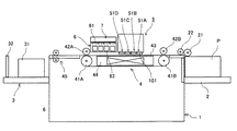
以下、本発明の実施の形態について添付図面を参照して説明する。まず、本発明に係る画像形成装置の一例について図1及び図2を参照して説明する。なお、図1は同画像形成装置の全体構成を説明する概略構成図、図2は同装置の模式的平面説明図である。 Embodiments of the present invention will be described below with reference to the accompanying drawings. First, an example of an image forming apparatus according to the present invention will be described with reference to FIGS. 1 is a schematic configuration diagram for explaining the overall configuration of the image forming apparatus, and FIG. 2 is a schematic plan explanatory diagram of the apparatus.
この画像形成装置はライン型画像形成装置であり、装置本体1と、用紙Pを積載し給紙する給紙トレイ2と、印刷された用紙Pを排紙積載する排紙トレイ3と、用紙Pを給紙トレイ2から排紙トレイ3まで搬送する搬送部4と、搬送部4によって搬送される用紙Pに液滴を吐出し印字する記録ヘッドを構成するヘッド部5と、印刷終了後又は所要のタイミングでヘッド部5の各記録ヘッドの維持回復を行う維持回復機構であるヘッドメンテナンス装置6と、ヘッドメンテナンス装置6のキャップ部材、ワイパ部材(ブレード手段)を清掃(クリーニング)するワイパ清掃手段であるクリーナ装置7とを備えている。
This image forming apparatus is a line type image forming apparatus, and includes an apparatus
装置本体1は、図示しない前後側板及びステーなどで構成されており、給紙トレイ2上に積載されている用紙Pは、分離ローラ21及び給紙ローラ22によって1枚ずつ搬送部4に給紙される。
The apparatus
搬送部4は、搬送駆動ローラ41Aと搬送従動ローラ41Bと、これらのローラ41A、41B間に掛け回された無端状の搬送ベルト43とを備えている。この搬送ベルト43の表面には複数の図示しない穴が形成されており、搬送ベルト43の下部には用紙Pを吸引する吸引ファン44が配置されている。また、搬送駆動ローラ41A、搬送従動ローラ41B上部には、それぞれ搬送ガイドローラ42A、42Bが図示しないガイドに保持されて、自重にてベルト43に当接している。
The
搬送ベルト43は、搬送駆動ローラ41Aが図示しないモータにより回転されることで周回移動し、用紙Pは搬送ベルト43上に吸引ファン44により吸い付けられ、搬送ベルト43の周回移動によって搬送される。なお、搬送従動ローラ41B、搬送ガイドローラ42A、42Bは搬送ベルト43に従動して回転する。
The
搬送ユニット4の上部には用紙Pに印字する液滴を吐出する複数の記録ヘッドで構成されるヘッド部5が移動可能(ここでは昇降可能)に配置されている。このヘッド部5は、維持回復動作時(メンテナンス時)にはメンテナンス装置6がヘッド部5の下方まで進入してくるスペースを確保する位置まで上昇する。
A
ヘッド部5は、図3にも示すように、ベース部材52に一列に配列した複数(この例では5個)のヘッド101で構成される4つのヘッド列51A〜51Dを有するヘッドユニット(記録ヘッド)50を備えている。ヘッド101は、液滴を吐出する複数のノズル102がノズル面104に2列配列されている。そして、ヘッド列51A、51Bの各ヘッド101の2つのノズル列の一方でイエロー(Y)の液滴を、他方でマゼンタ(M)の液滴を吐出し、また、ヘッドモジュール51C、51Dの2つのノズル列の一方でシアン(C)の液滴を、他方でブラック(K)の液滴を吐出する。つまり、ヘッド部5は、同じ色の液滴を吐出する2つのヘッド列51が用紙搬送方向に並べて配置され、2つのヘッド列51で用紙幅相当の1列分のノズル列が構成されている構成としている。ここでは、150dpiの画像1ラインとしている。
As shown in FIG. 3, the
なお、各色のライン構成は、上記に限るものではなく、各色の配置は特に限定はない。また、ヘッド部の構成も、この例に限るものではなく、例えば上記ヘッド部を2個並べて1ヘッド列に1色を割り当て、画像解像度を上記の2倍にした構成などとすることもできる。 The line configuration of each color is not limited to the above, and the arrangement of each color is not particularly limited. Further, the configuration of the head unit is not limited to this example, and for example, a configuration in which two head units are arranged, one color is assigned to one head row, and the image resolution is doubled as described above may be used.
また、ヘッド部5には、記録ヘッド50の各ヘッド101にインクをそれぞれ供給する分岐部材が各色ごとに配列され、分岐部材上流側にはサブタンクが配置され、サブタンクとヘッドとの水頭差によって、ヘッド101のノズル102のメニスカスを保持するのに適切な負圧が形成される。さらに、サブタンク上流側にはインクを貯蔵する交換可能なメインタンクが配置されている。
Further, in the
搬送部4の下流側には用紙Pを排紙トレイ3に排紙する搬送ガイド部45が配置されている。搬送ガイド45にて搬送された用紙Pは排紙トレイ3に排紙される。排紙トレイ3は、用紙Pの幅方向を規制する対のサイドフェンス31と用紙Pの先端を規制するエンドフェンス32を備えている。
A
搬送部4の上方でヘッド部5の側方には、ヘッド101のノズル面104をメンテナンスするメンテナンス装置6が配置されている。メンテナンス装置6は、図4にも示すように、ヘッド列51A〜51Dの各ヘッド101に対応してノズル面104をキャッピングするキャップ61と、各ヘッド101に対応してノズル面104をワイピングするブレード状のワイパ(ワイパブレード)62と、1列分のキャップ61内を吸引する吸引手段63などを有している(なお、図4では1つのヘッド(ヘッド列)に対応する部分のみ示している。)。このメンテナンス装置6は、キャップ61にてヘッド101のノズル面104を密閉した状態で吸引手段63によって吸引することでノズル102から増粘したインクを排出させてヘッド101の吐出性能を回復させる。ワイパブレード62はブレードホルダ65に保持されている。
A
なお、メンテナンス装置6の吸引手段63やキャップ61と吸引手段63をつなぐ流路、その他圧力室等は、装置本体1の後側板の外側に配置し、チューブ等の経路を使用して接続することもできる。また、維持回復時に吸引に代えて、あるいは吸引とともにヘッド101の上流側から加圧手段によってヘッド101内を加圧する構成とすることもできる。
The suction means 63 of the
このメンテナンス装置6は、搬送部4の上方で用紙搬送方向に沿ってスライド移動可能に配置され、ヘッドメンテナンス時にはヘッド部5が上昇した後ヘッド部5の下部に移動し、印字中は図1の位置に退避する。
The
メンテナンス装置6の上部にはキャップ61及びワイパブレード62に付着した液滴(廃液)を清掃するクリーナ装置7が配置されている。このクリーナ装置7は、図示しないクリーナ移動手段によって用紙搬送面に対して鉛直方向に上下移動可能に配置されている。ヘッド101のメンテナンスが終了したメンテナンス装置6がヘッド部5の側方に退避した状態において、クリーナ装置7が下降移動し、キャップ61及びワイパブレード62を清掃する。
A
次に、この画像形成装置における維持回復動作について図5のフロー図及び図6の説明図をも参照して説明する。
まず、ヘッド部5のヘッド101から液滴を吐出し画像形成を行っているとき(印刷中)は、ヘッド部5、メンテナンス装置6及びクリーナ装置7は図6(a)に示す状態にある。そして、印刷が終了し、あるいは、ヘッドのメンテナンス信号、もしくは、ヘッドの待機信号が入力されると、ヘッド部5のメンテナンスを行う動作に移行し、図6(b)にも示すように、クリーナ装置7が矢示A方向に移動(上昇)し、ヘッド部5が矢示B方向に移動(上昇)して退避位置になる。
Next, the maintenance and recovery operation in the image forming apparatus will be described with reference to the flowchart of FIG. 5 and the explanatory diagram of FIG.
First, when an image is formed by discharging droplets from the
次いで、図6(c)にも示すように、メンテナンス装置6が矢示C方向にスライド移動してヘッド部5の下側のメンテナンス位置に移動する。そして、図6(d)にも示すように、ヘッド部5が所定量下降移動してヘッド部5のヘッド101のノズル面104がキャップ61にてキャッピングされ、この状態で維持回復動作(メンテナンス動作)が行われる。
Next, as shown in FIG. 6C, the
なお、待機時にはヘッド101のノズル面104をキャップ61にてキャッピングした状態となり、ノズル102内のインクの乾燥を防止する。
During standby, the
そして、ヘッドの待機、メンテナンス動作が終了し、吐出信号が入ったときには、上記動作とは逆の動作にて、ヘッド部5が所定量上昇し、メンテナンス装置6が矢示C方向とは反対方向にスライド移動して退避位置に戻り、ヘッド部5はメンテナンス装置6が退避したときに所定の印字位置まで下降し、クリーナ装置7が下降してメンテナンス装置6のキャップ61及びワイパブレード62の清掃を行う。
When the head standby and maintenance operations are completed and an ejection signal is received, the
次に、メンテナンス動作について図7を参照して説明する。
図7(a)に示すように、メンテナンス装置6がヘッド部5の下方のメンテナンス位置に移動した後、図7(b)に示すように、ヘッド部5が下降してヘッド101にキャップ61の当接部61aが当接しノズル面104をキャッピングする。そして、吸引手段63で吸引することでヘッド101のノズル102からインクを吸引排出することで増粘インクや気泡などを排出してメンテナンスを行う。
Next, the maintenance operation will be described with reference to FIG.
As shown in FIG. 7A, after the
吸引終了後、図7(c)に示すように、ヘッド部5が所定量上昇してキャップ61がヘッド101のノズル面104から離間し、ヘッド部5はワイパブレード62によるワイピング高さ位置になる。このとき、ヘッド101のノズル面104とワイパブレード62の高さにはある程度の食込み量が必要であるため、キャップ61の当接部(当接面)62aとワイパブレード62との間には高さhが必要となる。
After the completion of the suction, as shown in FIG. 7C, the
そして、図7(d)に示すように、メンテナンス装置6が矢示方向に移動して、ワイパブレード62によってヘッド101のノズル面104をワイピングし、ノズル面104に付着している廃液200を除去する。このとき、ワイパブレード62には天面62aと払拭面62bの両方に廃液200が付着しており、このままの状態で次のワイピングを行うとヘッド101のノズル面104に再転写してしまいメンテナンス不良を起こしてしまう可能性があるため、クリーナ装置7にてワイパブレード62に付着した廃液200を除去する。
Then, as shown in FIG. 7D, the
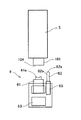
そこで、この画像形成装置に適用する本発明の第1実施形態におけるクリーナ装置7について図8及び図9をも参照して説明する。なお、図8はクリーナ装置の模式的説明図、図9は図8の側面説明図である。ここでは、説明を簡単にするため、1つのキャップ及びワイパ部材に対応するもので説明する。
Therefore, the
このクリーナ装置7は、吸収体部材であるウェブ状のワイパクリーナ71を有している。このワイパクリーナ71の幅Lはワイパブレード62の幅Iよりも広く形成されている。そして、ワイパクリーナ71は、供給ローラ72に巻回されて順次巻取りローラ73で巻き取られる。このワイパクリーナ71の移動経路は、所要の位置に配置されたガイド部材74とテンションローラ76にて形成されている。
This
ここで、ガイド部材74には、ワイパブレード62の天面62a及び払拭面62bを挟み込む挟み込み清掃部75が形成されている。この挟み込み清掃部75は、ワイパブレード62の厚さに対してほぼ同じ、あるいはやや大きく下に向けて凹形状となっている。ここに、ワイパブレード62が下方より押し上げることでワイパクリーナ71が挟み込み清掃部75の形状に沿って変形し、ワイパブレード62の天面62aと払拭面62bを同時に挟み込む。ワイパクリーナ71によりワイパブレード62の天面62aと払拭面62bを同時に挟み込むことで、天面62aと払拭面62bを同時に清掃することができ付着している廃液を除去することができる。
Here, the
また、ワイパブレード62とキャップ61との高さ位置を設定することで、ワイパブレード62の清掃を行うときにキャップ61もワイパクリーナ71に当接させて清掃することができる。
In addition, by setting the height positions of the
ワイパクリーナ71を構成する吸収体部材は廃液を吸収することができる不織布で形成している。材質はPETなど、廃液を吸収可能な不織布であれば特に限定されない。不織布は廃液をより吸収することができ、かつ、厚みが薄いほうが供給ローラ72に巻き付く量を多くすることができ、結果、クリーナ装置7の寿命を長くすることができる。すなわち、ワイパクリーナ71は、厚みが薄く、吸収性の良い不織布が好ましい。
The absorbent member constituting the
また、巻取りローラ73は、図示しない、ギヤ、タイミングベルトを介して駆動手段である巻取りモータ77によって回転され、巻取りローラ73が回転することでワイパクリーナ71が矢示方向に移動する。
The take-up
なお、ここでは、ワイパブレード62側が下方から押し上げる構成としているが、クリーナ装置7側が上方から下がる構成とすることもできる。
Here, the
次に、このクリーナ装置7によるクリーニング動作について図10にフロー図及び図11の説明図を参照して説明する。
先ず、図11(a)に示すように、メンテナンス装置6のワイパブレード62がクリーナ装置7の挟み込み清掃部75の下部に待機したとなる。そして、図11(b)に示すように、ワイパブレード62が上昇し、挟み込み清掃部75に押し込まれる。このとき、ワイパクリーナ71のたるみを形成する必要がある。すなわち、図11(a)の状態からワイパブレード62を押し上げても、ワイパクリーナ71は巻取りローラ73の矢印方向の回転によって巻き取られ、張った状態にある。そこで、一旦、図11(b)に示すように、巻取りモータ73を巻取り方向とは逆の方向に回転させ、ワイパクリーナ71にたるみを形成させた状態で、ワイパブレード62を挟み込み清掃部75に押し込み、ワイパクリーナ71を挟み込み清掃部75に沿わせる。
Next, the cleaning operation by the
First, as shown in FIG. 11A, the
このワイパブレード62が押し込まれた状態では、ワイパブレード62の天面62aに付着している廃液を除去するため一定時間(当接時間)停止させる。このとき、ワイパクリーナ71は払拭面62bにも接触するが、更にクリーニング性を向上させるために、ワイパブレード62が挟み込み清掃部75に挟み込まれた状態のまま、ワイパブレード62を図11(b)で左方向に微小量スライド移動させ、ある一定時間(当接時間)停止させてクリーニングを行う。
In a state where the
その後、ワイパブレード62を下降させ、クリーナ装置7の巻取りモータ73を駆動して(ON)、巻取りローラ73にワイパクリーナ71を指定巻取り量(設定巻取り量)だけ巻き取らせ、巻取りモータ73を停止させる(OFF)。このとき、ワイパクリーナ71は挟み込み清掃部75に沿わず、ガイド部材74に沿って張られる。
Thereafter, the
これにより、ワイパクリーナ71による新しい清掃部分が挟み込み清掃部75の位置に移動し、継続的に効果的な清掃を行うことができる。つまり、同じ位置でワイパブレード62の清掃をしていると、ワイパクリーナ71への廃液の吸収量に対してキャパオーバーとなってしまい、きれいに除去することができず、逆にワイパブレード62に廃液を再転写してしまい、そのままヘッドのワイピングを行うとノズル面に再転写してしまうことになるので、ワイパブレード62のクリーニングを実施するごとにワイパクリーナ71を移動させて、新しい部分を清掃位置にすることでワイパブレード62に付着した廃液をきれいに拭き取ることができるようにしている。
Accordingly, a new cleaning portion by the
なお、ここではクリーニングを行うたびにワイパクリーナ71を所定量移動させているが、ワイパクリーナ71の吸収量によっては数回同一面でワイパブレード62をクリーニングした後、巻取りローラでワイパクリーナ71を巻き取るようにすることもでき、このようにすれば、ワイパクリーナ71の寿命を長くすることができる。
Here, the
また、キャップ61とワイパブレード62の高さ位置関係を設定して、ワイパブレード62を挟み込み清掃部75に押し込んだ状態でキャップ61の当接部61aがワイパクリーナ71に当接するようにすることで、ワイパクリーナ71によってワイパブレード62とともにキャップ61も清掃することができる。
Further, the height positional relationship between the
つまり、前述したメンテナンス動作では、キャップ61の当接部61aがヘッド101のノズル面104に当接するが、このとき当接部61aに廃液が付着する。ワイピング後にヘッド待機状態に移行し、ヘッド101の乾燥防止のためにキャップ61でキャッピングを行うと、キャップ61に付着している廃液がノズル面104に転写されてキャップ痕がつき、このキャップ痕が乾燥した状態ではワイピングによる清掃が十分でなくなるので、キャップ61に付着した廃液も併せて除去するようにすることが好ましい。
That is, in the maintenance operation described above, the
次に、本発明の第2実施形態におけるクリーナ装置7について図12及び図13をも参照して説明する。なお、図12は同クリーナ装置の模式的説明図、図13は図12の側面説明図である。
ここでは、挟み込み清掃部75として、ガイド部材74に代えて、ワイパブレード62を挟み込む部分の両側にガイド軸部材78、78を配置して、ガイド軸部材78、78間にワイパブレード62が入り込むスペースを形成し、ワイパブレード62が入り込むことでワイパクリーナ71がワイパブレード62の払拭面62b、天面62aに倣った形状に変形する。ガイド軸部材にすることでガイド部の挟み込み清掃部の形成が簡易的な構成でできる。
Next, the
Here, instead of the
次に、本発明の第3実施形態におけるクリーナ装置7について図14をも参照して説明する。なお、図14は同クリーナ装置の模式的説明図である。
ここでは、上記第2実施形態の構成に加えて、挟み込み清掃部75のガイド軸部材78、78をワイパブレード62を挟み込む方向に押圧する押圧部材としてのスプリング79、79を配置している。ワイパブレード62が挟み込み清掃部75に入り込むスペースは、ワイパブレード62より小さくしても、ワイパブレード62の侵入する力に対して、双方のガイド軸部材78、78が広がり、スプリング79、79の圧縮力によりワイパブレード62にワイパクリーナ71が押し付けられ、更にクリーニング性が向上する。
Next, the
Here, in addition to the configuration of the second embodiment, springs 79 and 79 are disposed as pressing members that press the
次に、本発明の第4実施形態におけるクリーナ装置7について図15をも参照して説明する。なお、図15は同クリーナ装置の模式的説明図である。
前述したように、ワイパブレード62を挟み込み清掃部75に押し込むときにはワイパクリーナ71にたるみを形成する必要がある。そこで、ここでは、供給ローラ72側にも駆動可能な供給モータ170を配置し、供給ローラ170を矢印方向に回転させてワイパクリーナ71を送ることでたるみを形成するようにしている。
Next, the
As described above, it is necessary to form a slack in the
次に、本発明の第5実施形態におけるクリーナ装置7について図16をも参照して説明する。なお、図16は同クリーナ装置の模式的説明図である。
ここでは、ワイパブレード62を挟み込み清掃部75に押し込むときにはワイパクリーナ71にたるみを形成するための構成として、駆動手段によるたるみ形成ではなく、供給ローラ72の軸部72aにギヤ171を設け、このギヤ171に係合する板ばね172を設けたラチェット機構を備えている。
Next, the
Here, as a configuration for forming a slack in the
ここで、ギヤ171のピッチをワイパブレード62がワイパクリーナ71を押し込む量と同じにすることで、ワイパブレード62をワイパクリーナ71に押し込む力によって、ワイパクリーナ71が送り出され、ピッチ分に達したときに板ばね172によってある力がかかりロックする構成としている。つまり、ワイパブレード62を挟み込み清掃部75に押し込むとき、ラチェット機構のギヤ171のピッチ分だけワイパクリーナ71の送り量がフリーとなっているため、容易にたるみを形成でき、ワイパブレード62が挟み込み清掃部75に押し込まれる分だけのワイパクリーナ71の送り量が確保される。
Here, when the pitch of the
次に、同画像形成装置におけるワイパクリーナ装置の全体構成について図17をも参照して説明する。
上述した画像形成装置では、ヘッド列51A〜51Dに対応してワイパブレード62も4列分配置されているので、クリーナ装置7の挟み込み清掃部75は4個設けている。つまり、ヘッド列数分の挟み込み清掃部75を設けることで対応することができる。
Next, the overall configuration of the wiper cleaner apparatus in the image forming apparatus will be described with reference to FIG.
In the image forming apparatus described above, four
この場合、所定回のクリーニング動作に対してワイパクリーナ71を4列相当分送ることもできるが、所定量ずつ送ることもできる。所定量ずつ送る場合、上流側のワイパブレードの清掃に使用された部分が下流側のワイパブレードに清掃位置に重複しないように送り量を設定することが好ましい。また、巻取りローラ73の近傍には、ワイパクリーナのエンド検知手段を配置して交換を促せるようにすることが好ましい。
In this case, the wiper cleaner 71 can be sent corresponding to four rows for a predetermined cleaning operation, but can also be sent by a predetermined amount. When feeding by a predetermined amount, it is preferable to set the feed amount so that the portion used for cleaning the upstream wiper blade does not overlap the downstream wiper blade at the cleaning position. Further, it is preferable that an end detection means of a wiper cleaner is disposed in the vicinity of the winding
なお、上記実施形態では本発明をライン型画像形成装置に適用した例で説明したが、シリアル型画像形成装置にも適用することができる。 In the above-described embodiment, the example in which the present invention is applied to the line type image forming apparatus has been described. However, the present invention can also be applied to a serial type image forming apparatus.
1 装置本体
2 給紙トレイ
3 排紙トレイ
4 搬送部
5 ヘッド部
6 メンテナンス装置
7 クリーナ装置
50 ヘッドユニット(記録ヘッド)
61 キャップ
62 ワイパブレード
71 ワイパクリーナ
72 供給ローラ
73 巻取りローラ
74 ガイド部材
75 挟み込み清掃部
101 ヘッド
DESCRIPTION OF
61
Claims (3)
前記記録ヘッドのノズル面を払拭するブレード状のワイパ部材と、
前記ワイパ部材に付着した廃液を除去するワイパ清掃手段と、を備え、
前記ワイパ清掃手段は、
連続する1枚のウエブを有し、
前記ウエブにより、前記ワイパ部材の天面及び払拭面を同時に挟み込んで、前記ワイパ部材の天面及び払拭面に付着した廃液を除去する
ことを特徴とする画像形成装置。 A recording head having nozzles for discharging droplets;
A blade-like wiper member for wiping the nozzle surface of the recording head;
Wiper cleaning means for removing waste liquid adhering to the wiper member,
The wiper cleaning means includes
Having one continuous web,
The web, the said top surface and the wiping surface of the wiper member crowded viewed clamping simultaneously, the image forming apparatus characterized by removing the waste liquid adhering to the top surface and the wiping surface of the wiper member.
Priority Applications (1)
| Application Number | Priority Date | Filing Date | Title |
|---|---|---|---|
| JP2009176067A JP5353530B2 (en) | 2009-07-29 | 2009-07-29 | Image forming apparatus |
Applications Claiming Priority (1)
| Application Number | Priority Date | Filing Date | Title |
|---|---|---|---|
| JP2009176067A JP5353530B2 (en) | 2009-07-29 | 2009-07-29 | Image forming apparatus |
Publications (2)
| Publication Number | Publication Date |
|---|---|
| JP2011025621A JP2011025621A (en) | 2011-02-10 |
| JP5353530B2 true JP5353530B2 (en) | 2013-11-27 |
Family
ID=43634938
Family Applications (1)
| Application Number | Title | Priority Date | Filing Date |
|---|---|---|---|
| JP2009176067A Active JP5353530B2 (en) | 2009-07-29 | 2009-07-29 | Image forming apparatus |
Country Status (1)
| Country | Link |
|---|---|
| JP (1) | JP5353530B2 (en) |
Families Citing this family (12)
| Publication number | Priority date | Publication date | Assignee | Title |
|---|---|---|---|---|
| JP5875341B2 (en) * | 2011-11-24 | 2016-03-02 | 株式会社ミマキエンジニアリング | Maintenance device and droplet discharge device |
| JP6007624B2 (en) * | 2012-07-03 | 2016-10-12 | 株式会社リコー | Image forming apparatus |
| JP6497024B2 (en) | 2014-05-21 | 2019-04-10 | 株式会社リコー | Droplet discharge head recovery mechanism |
| JP6308096B2 (en) * | 2014-10-10 | 2018-04-11 | 京セラドキュメントソリューションズ株式会社 | Inkjet recording device |
| JP6299657B2 (en) * | 2015-04-22 | 2018-03-28 | 京セラドキュメントソリューションズ株式会社 | Inkjet recording device |
| JP6569445B2 (en) * | 2015-10-07 | 2019-09-04 | 株式会社リコー | Inkjet recording device |
| JP6562870B2 (en) | 2016-04-28 | 2019-08-21 | キヤノンファインテックニスカ株式会社 | Recording device and cleaning mechanism life determination method |
| JP6977566B2 (en) * | 2018-01-05 | 2021-12-08 | 株式会社リコー | Liquid discharge device and nozzle surface cleaning device |
| JP7085132B2 (en) * | 2018-09-07 | 2022-06-16 | 株式会社リコー | Roll unit, roll device, head maintenance device, liquid discharge device |
| JP7255246B2 (en) * | 2019-03-08 | 2023-04-11 | 京セラドキュメントソリューションズ株式会社 | Recording head maintenance device and inkjet recording device provided with the same |
| JP2021098323A (en) | 2019-12-23 | 2021-07-01 | 株式会社リコー | Wiping device, head maintenance device, and device for discharging liquid |
| JP2021123038A (en) | 2020-02-06 | 2021-08-30 | 株式会社リコー | Head maintenance device, liquid discharge device, and printer |
Family Cites Families (8)
| Publication number | Priority date | Publication date | Assignee | Title |
|---|---|---|---|---|
| US5589861A (en) * | 1994-05-31 | 1996-12-31 | Hewlett-Packard Company | Cleaner cartridge for an inkjet printing mechanism |
| JPH0872256A (en) * | 1994-09-09 | 1996-03-19 | Brother Ind Ltd | Ink jet device |
| JPH10100426A (en) * | 1996-09-27 | 1998-04-21 | Citizen Watch Co Ltd | Ink jet recorder |
| JPH1120187A (en) * | 1997-07-01 | 1999-01-26 | Ricoh Co Ltd | Ink-jet recording apparatus |
| JP2000177140A (en) * | 1998-12-17 | 2000-06-27 | Oki Data Corp | Recording head cleaning mechanism |
| JP3937207B2 (en) * | 1999-10-14 | 2007-06-27 | セイコーエプソン株式会社 | Ink jet print head and ink jet printer |
| JP4570865B2 (en) * | 2003-12-15 | 2010-10-27 | 株式会社リコー | Head cleaning device and image forming apparatus |
| JP4802173B2 (en) * | 2006-11-24 | 2011-10-26 | 京セラミタ株式会社 | Inkjet recording device |
-
2009
- 2009-07-29 JP JP2009176067A patent/JP5353530B2/en active Active
Also Published As
| Publication number | Publication date |
|---|---|
| JP2011025621A (en) | 2011-02-10 |
Similar Documents
| Publication | Publication Date | Title |
|---|---|---|
| JP5353530B2 (en) | Image forming apparatus | |
| EP2364854B1 (en) | Image forming apparatus | |
| JP5347687B2 (en) | Image forming apparatus | |
| US9381744B2 (en) | Image forming apparatus including recovery device to recover droplet discharge head | |
| US8297733B2 (en) | Ink jet recording apparatus having recovery device | |
| JP4305529B2 (en) | Inkjet recording device | |
| JP5228710B2 (en) | Image forming apparatus | |
| JP2010046807A (en) | Image forming apparatus | |
| JP6069994B2 (en) | Cap member, liquid ejection device, and image forming apparatus | |
| JP2011011498A (en) | Image forming apparatus | |
| JP2007283624A (en) | Image forming apparatus | |
| JP5822733B2 (en) | Nozzle surface cleaning device and image recording device | |
| JP6658609B2 (en) | Recording head recovery system and ink jet recording apparatus provided with the same | |
| JP2011084004A (en) | Image forming apparatus | |
| JP2010058473A (en) | Head cleaning device and image forming apparatus using the same | |
| JP6579090B2 (en) | Recording head and ink jet recording apparatus provided with the same | |
| JP6658571B2 (en) | Recording head recovery system and ink jet recording apparatus provided with the same | |
| JP6589893B2 (en) | Head cleaning mechanism and ink jet recording apparatus having the same | |
| JP2009172952A (en) | Recording device | |
| JP6579091B2 (en) | Recording head and ink jet recording apparatus provided with the same | |
| JP5009817B2 (en) | Image forming apparatus | |
| JP2014008763A (en) | Image forming apparatus | |
| JP6973185B2 (en) | Liquid discharge unit and liquid discharge device | |
| JP2010058348A (en) | Image forming apparatus | |
| JP6673254B2 (en) | Head cleaning mechanism and ink jet recording apparatus having the same |
Legal Events
| Date | Code | Title | Description |
|---|---|---|---|
| A621 | Written request for application examination |
Free format text: JAPANESE INTERMEDIATE CODE: A621 Effective date: 20120528 |
|
| A977 | Report on retrieval |
Free format text: JAPANESE INTERMEDIATE CODE: A971007 Effective date: 20130508 |
|
| A131 | Notification of reasons for refusal |
Free format text: JAPANESE INTERMEDIATE CODE: A131 Effective date: 20130515 |
|
| A521 | Written amendment |
Free format text: JAPANESE INTERMEDIATE CODE: A523 Effective date: 20130531 |
|
| TRDD | Decision of grant or rejection written | ||
| A01 | Written decision to grant a patent or to grant a registration (utility model) |
Free format text: JAPANESE INTERMEDIATE CODE: A01 Effective date: 20130730 |
|
| A61 | First payment of annual fees (during grant procedure) |
Free format text: JAPANESE INTERMEDIATE CODE: A61 Effective date: 20130812 |
|
| R151 | Written notification of patent or utility model registration |
Ref document number: 5353530 Country of ref document: JP Free format text: JAPANESE INTERMEDIATE CODE: R151 |